web-based access control solution quick install guide
TRANSCRIPT
ACW2-XN Web-based Access Control Solution
Quick Install Guide
ACW2XN-901-EN, Rev. A.1 PLT-03473 A.1
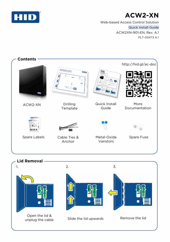
Contents
Lid Removal
ACW2-XN
Spare Labels Cable Ties & Anchor
Metal-Oxide Varistors
Spare Fuse
1. 2. 3.
Open the lid & unplug the cable
Drilling Template
Quick Install Guide
More Documentation
Slide the lid upwards Remove the lid
http://hid.gl/ac-doc

AC AW2
Basic Installation
1. Mount the ACW2-XN to the desired location. Use the Drilling template to aid in marking the mounting holes.
2. Wire the readers to the AW2. 3. Wire the desired inputs to the AW2. 4. Wire the locks to the AW2 relay terminals. 5. Connect the Ethernet cable to the Controller (AC). 6. Place the AC and AW2 labels in the correct location on the back
page of this quick guide. This will be used during door setup. 7. Unplug the power mains cable then wire it to the Power Terminal
Block. 8. Check all wiring then, if everything is satisfactory, plug in the
mains cable to power up the ACW2-XN.
12V DC Power Input
RS-485 Ports
Relay 1
Inputs 1
Relay 2
Inputs 2
Reader 1 Reader 2
Note: It is recommended that a 3
rd party 12VDC battery be added to
the system. Please see the Installation Guide for details and advanced
features.
1. Set the controller(AC) dip switch #1 ON 2. Reboot the controller and wait until the
status LED is constantly RED (~30 sec). 3. Set the controller(AC) dip switch #1
OFF 4. Reboot the controller
Caution: Factory default will erase all data stored within the controller!
Network
Remove Tag
Factory Default (Last Resort Only)
Copyright © 2018 HID Global Corporation/ASSA ABLOY AB. All rights reserved. This document may not be reproduced, disseminated or republished in any form without the prior written permission of HID Global Corporation.

Power Supply (A-X1)
AC Mains Input 100-230 VAC (50/60Hz), 1.3A
DC Output 12V, 5A
Controller (AC)
Power Input 12V DC (Factory Pre-wired)
Network 10/100 Base T, half or full duplex
Wiegand Module (AW2)
Relay Rating [10A, 28VDC] [5A, 220VAC] [12A, 120VAC]
Recommended Cable Specifications
Input & Wiegand: >=22AWG, Max 150m Relay: >=18AWG, Max 150M
Specifications
HID Access Manager
Initial Connection Using a Router with DNS active
Type: “//HIDaccess/” as the URL of any HTML5 compliant web browser such as Chrome
Using a Switch or Direct Connection: Type: “//192.168.100.1/” as the URL of any HTML5 compliant
web browser such as Chrome The client PC must be in the same subnet (192.168.100.#)
Default Password: “12345” Required Settings
1. Set the date and time 2. Update the master password 3. Add/Configure doors and readers 4. Add/Manage people
Note: It is best practice to use an additional fused power supply for the locks
Trademarks HID GLOBAL, HID, the HID Brick logo, the Chain Design, ICLASS, ICLASS SE, SEOS, and OMNIKEY are trademarks or registered trademarks of HID Global, ASSA ABLOY AB, or its affiliate(s) in the US and other countries and may not be used without permission. All other trademarks, service marks, and product or service names are trademarks or registered trademarks of their respective owners.

A
W2
A
W2
A
W2
A
W2
A
C
Do
or N
ames
Do
or N
ames
Do
or N
ames
Do
or N
ames