wave phenomena - harvard university department of...
TRANSCRIPT

Wave Phenomena Physics 15c
Lecture 8 LC Transmission Line
Wave Reflection

Midterm Exam #1 Midterm #1 has been graded Class average = 80.4 Standard deviation = 14.6
Your exam will be returned in the section Contact your TF is you can’t make
this week’s section
If you are concerned about your grade, please email me and we will discuss plans for the rest of the semester
!"
#"
$"
%"
&"
'"
("
)"
*"
+"
#!"
%'" &!" &'" '!" ''" (!" ('" )!" )'" *!" *'" +!" +'" #!!"
!"#$%$&'()*(+&,#$(
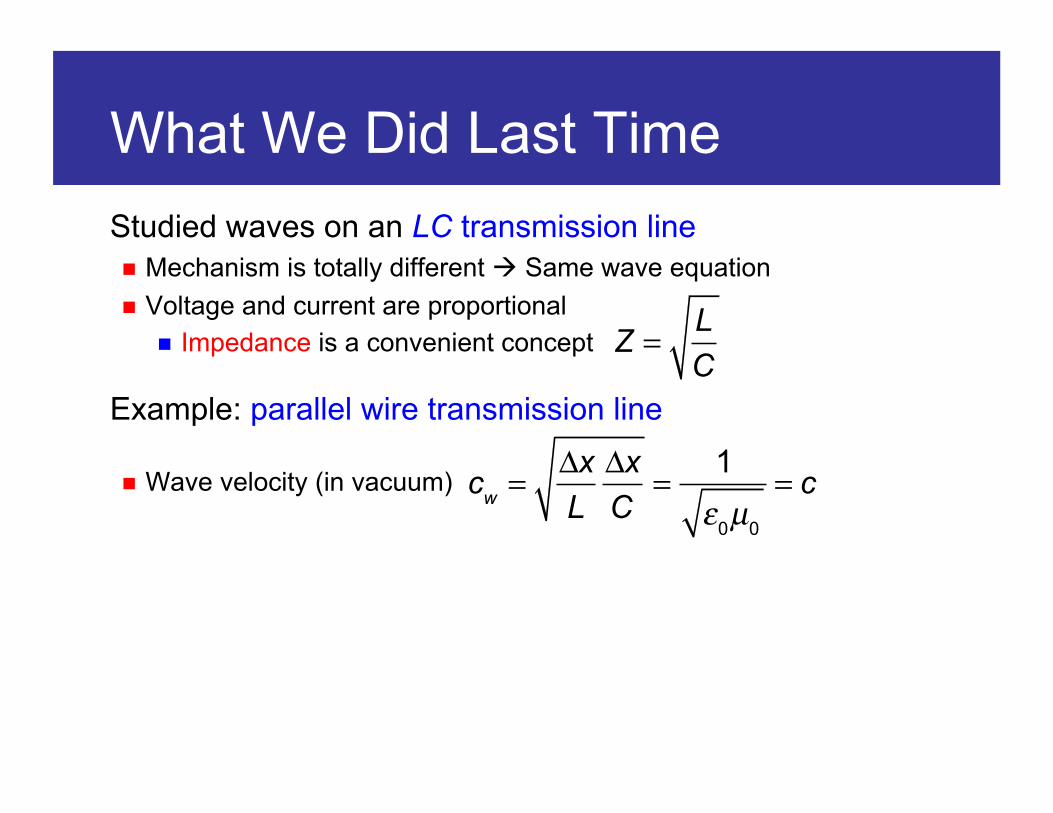
What We Did Last Time Studied waves on an LC transmission line Mechanism is totally different Same wave equation Voltage and current are proportional
Impedance is a convenient concept
Example: parallel wire transmission line
Wave velocity (in vacuum)
Z =
LC
cw =
ΔxL
ΔxC
=1ε0µ0
= c

Today’s Goals Energy and momentum density in the LC transmission line Transfer rate = power and force
Discuss where the energy is in electromagnetic waves It’s not in carried through the wires Recall Poynting vector from 15b/153
Also: coaxial cable Another example of an LC transmission line
Wave reflection What happens at the end of a transmission line?
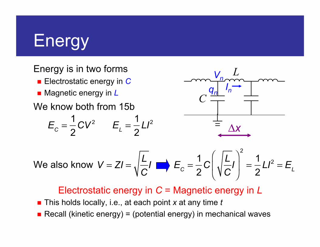
Energy Energy is in two forms Electrostatic energy in C Magnetic energy in L
We know both from 15b
We also know
Electrostatic energy in C = Magnetic energy in L This holds locally, i.e., at each point x at any time t Recall (kinetic energy) = (potential energy) in mechanical waves
Vn
qn In
Δx EC =
12
CV 2
EL =
12
LI2
V = ZI =
LC
I EC =
12
CLC
I⎛
⎝⎜
⎞
⎠⎟
2
=12
LI2 = EL

Energy Density Total energy density is given by
Multiply by the wave velocity to get the energy transfer rate
For a normal mode
Average energy density:
Average energy transfer rate:
dEdx
=2 × EC
Δx=
CΔx
V 2 =CΔx
VLC
I =LCΔx
VI =VIcw
dEdt
= cw
dEdx
=VI That’s power, as we should expect
V(x,t) =V0 cos(kx −ω t)
dEdx
=12
V0I0
cw
dEdt
=12
V0I0

Momentum Waves on an LC transmission line do carry momentum But we do not see any mass moving with it We can only see that forces are needed/produced at the ends of the
transmission line
Let’s drive a transmission line that is terminated
To create waves, the wires from the driving circuit must run across the gap between the wires
Same for the terminating resistor Current flows across the wires There is B field between the wires Lorentz force

Lorentz Force Magnetic field between the wires is
Lorentz force is It’s parallel to the direction of the wires
Backward (into the screen) at the driver Forward (out of the screen) at the terminator
Integrate I × B to calculate the total force
I
d – r
r
B =
µ0I2πr
+µ0I
2π(d − r )
F = I×B B
F = IB dra
d −a
∫ =µ0I
2
2π1r+
1d − r
⎛⎝⎜
⎞⎠⎟
dra
d −a
∫
=µ0I
2
πln d − a
a=
LΔx
I2
LΔx
=µ0
πln d − a
a
From last lecture

Lorentz Force
Using the impedance again
We can see this as the waves transmitting force Which is also the rate of momentum transfer
We find (momentum density) = (energy density)/(velocity)
F
F =
LΔx
I2 =LΔx
VIZ
=LΔx
CL
VI =LCΔx
VI =VIcw
F
F =
dpdt
=VIcw
momentum density =dpdx
=VIcw
2

Where is the Energy? Energy of waves on an LC transmission line is in L and C Where is “in” L and C? Energy in L is stored in the form of magnetic field Energy in C is stored in the form of electric field
Recall for the parallel-wire transmission line
Energy densities depend on the magnetic/electric properties µ and ε of the medium around the wires
The energy is not carried by the physical wires, but in the space around them as electromagnetic field Wires are guiding the waves, but not transmitting them
12
LΔx
I2 =12µπ
ln da
I2
12
CΔx
V 2 =12
πεln(d / a)
V 2

Parallel Wire Transmission Line Parallel wire transmission line is surrounded by E and B fields The energy is carried in these fields They extend to infinity
It’s a leaky way of carrying energy It may interfere with E or B fields
generated by nearby circuits Radiation loss becomes a problem at
higher frequencies
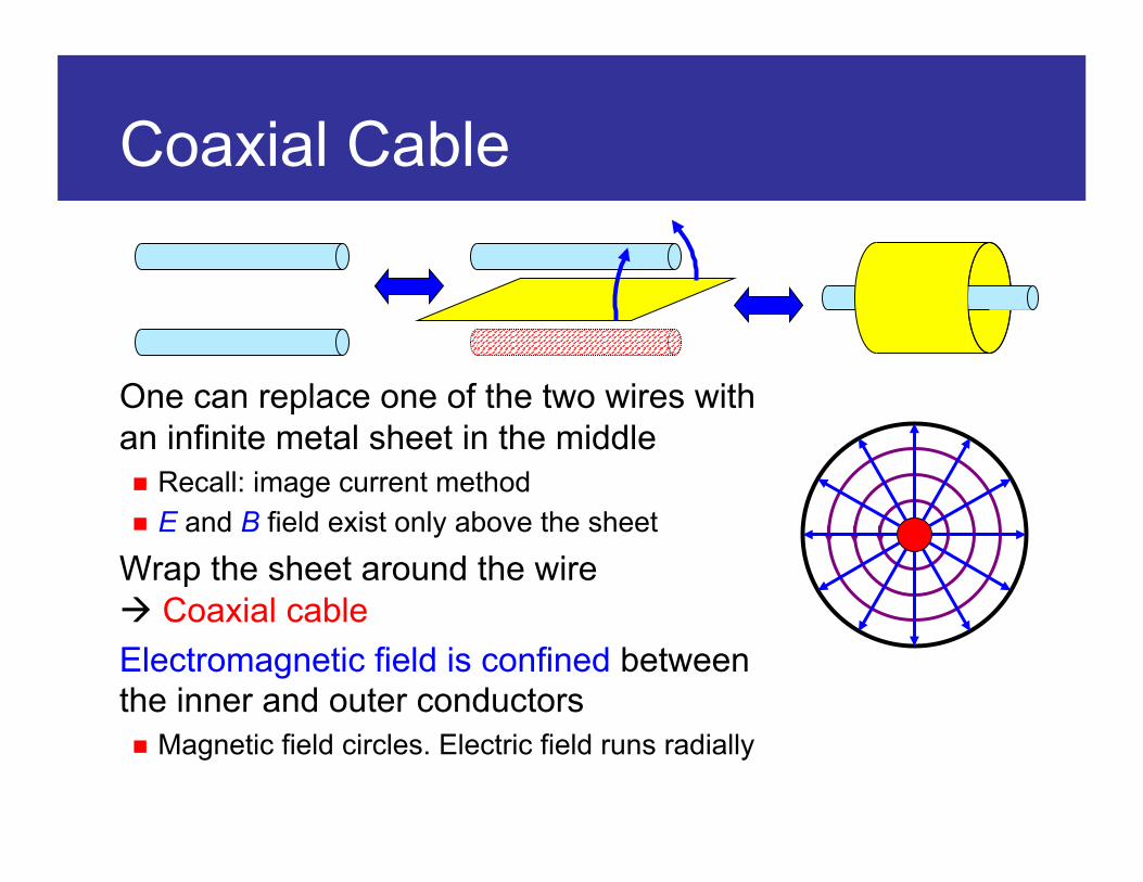
Coaxial Cable
One can replace one of the two wires with an infinite metal sheet in the middle Recall: image current method E and B field exist only above the sheet
Wrap the sheet around the wire Coaxial cable Electromagnetic field is confined between the inner and outer conductors Magnetic field circles. Electric field runs radially

Coaxial Cable L and C can be calculated using Physics 15b again For inner and outer radii of a and b
Derivation is left to the problem set
Impedance and wave velocities are
LΔx
=µ0
2πln b
a
CΔx
=2πε0
ln b / a( )
Z =
LC
=1
2πµ0
ε0
ln ba
cw =
ΔxLC
=1ε0µ0
= c
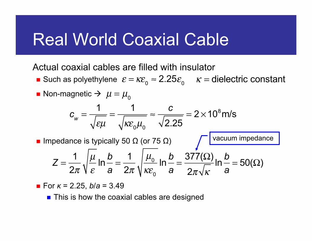
Real World Coaxial Cable Actual coaxial cables are filled with insulator Such as polyethylene
Non-magnetic
Impedance is typically 50 Ω (or 75 Ω)
For κ = 2.25, b/a = 3.49 This is how the coaxial cables are designed
ε =κε0 ≈ 2.25ε0 κ = dielectric constant
µ = µ0
Z =
12π
µε
ln ba=
12π
µ0
κε0
ln ba=
377(Ω)2π κ
ln ba= 50(Ω)
cw =
1εµ
=1
κε0µ0
≈c
2.25= 2 ×10⁸m/s
vacuum impedance

Energy Density Energy is carried in the space between the conductors It’s like an air-filled pipe in which sound is
traveling The cable/pipe looks like the medium, but
the true medium is inside them!
Poynting vector gives us the density of energy flow
Direction is perpendicular to both E and B For both parallel-wire and coaxial cables,
Poynting vector points the direction of wave transmission
S = E ×H = E ×
Bµ

Power Density In a coaxial cable, E and H at radius r is given by
ρ is the charge density of the inner wire I is the current on the inner wire
Poynting vector is Integrate this
E =
ρ2πε0r
H =I
2πr
S =
ρI4π 2ε0r
2
S dAA∫∫ =
ρI4π 2ε0r
2 r dr dϕa
b
∫0
2π
∫ =ρI
2πε0
1r
dra
b
∫ =ρI
2πε0
ln ba
= ρIΔxC
=QIC
=VI
CΔx
=2πε0
ln b / a( )Power carried by
the EM waves

Impedance Matching Characteristic impedance of an LC transmission line is a very useful concept It connects the voltage and the current: V = ZI An infinite LC transmission line ≈ a Z Ω resistor
If we send a signal through a 50 Ω coaxial cable terminated with a 50 Ω resistor, it will be absorbed Signal will vanish as if it went down on an infinite cable
What if we forgot to put the resistor? What if we terminated with 0 Ω? How about 100 Ω?
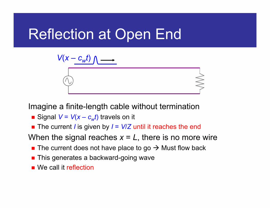
Reflection at Open End
Imagine a finite-length cable without termination Signal V = V(x – cwt) travels on it The current I is given by I = V/Z until it reaches the end
When the signal reaches x = L, there is no more wire The current does not have place to go Must flow back This generates a backward-going wave We call it reflection
V(x – cwt)
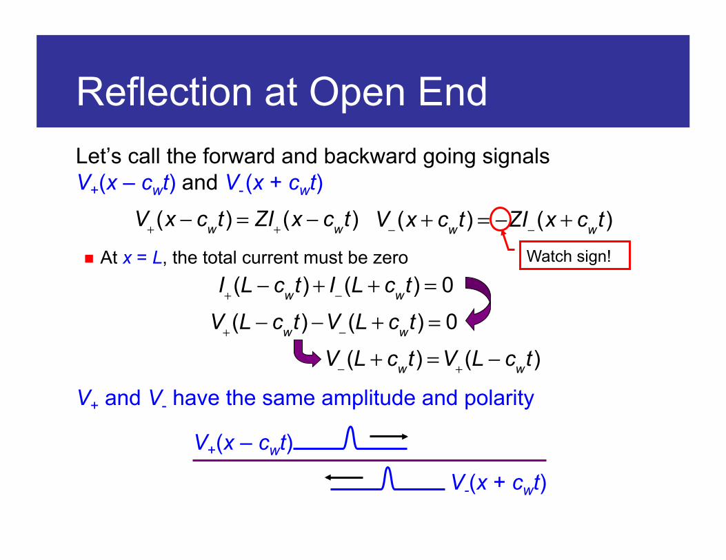
Reflection at Open End Let’s call the forward and backward going signals V+(x – cwt) and V- (x + cwt)
At x = L, the total current must be zero
V+ and V- have the same amplitude and polarity
V+(x − cwt) = ZI+(x − cwt) V−(x + cwt) = −ZI−(x + cwt)
I+(L − cwt) + I−(L + cwt) = 0
V+(L − cwt) −V−(L + cwt) = 0
V+(x – cwt)
V-(x + cwt)
V−(L + cwt) =V+(L − cwt)
Watch sign!

Reflection at Open End V+ and V− look the same V+ goes from x = 0 to L V- comes back from x = L to 0
I+ and I− look flipped because
Exactly what happens at x = L?
V+ = ZI+ V− = −ZI−
V+
V-
I+
I-

Mirror Waves Imagine the cable continued beyond x = L Imagine a backward going pulse is coming from x = 2L Two pulses meet at x = L
I+ and I− cancel each other Meet I = 0 constraint at x = L V+ and V− add up Double the pulse height at x = L
I+
I-
I- V+
V-
V-

Reflection at Shorted End
What if the end is short-circuited This time, the voltage is forced to be 0 at x = L
The reflected wave has the same amplitude but opposite polarity as the original wave
Current is given by
V(x – cwt)
V+(L − cwt) +V−(L + cwt) = 0
V+(x – cwt)
V-(x + cwt)
I−(L + cwt) = I+(L − cwt) V+ = ZI+ V− = −ZI−

Mirror Waves This time, the voltage is canceling out at x = L Current doubles at x = L
V+
V-
V- I+
I-
I-

Partial Reflection
An LC transmission line is terminated with a resistor that does not match its impedance It’s easy to guess the outcome: partial reflection Part of the energy is absorbed by the resistor Part of the energy will come back as a reflected wave
V(x – cwt)
R ≠ Z =
LC

Partial Reflection At x = L, V and I must satisfy Ohm’s law
Use V+ = ZI+ and V− = −ZI−
Solve for V−
Setting R = ∞ or 0 gives open/shorted-end solutions
V+(L − cwt) +V−(L + cwt) = R(I+(L − cwt) + I−(L + cwt))
V+(L − cwt) +V−(L + cwt) = R
ZV+(L − cwt) − R
ZV−(L + cwt)
V−(L + cwt) = R − Z
R + ZV+(L − cwt)
I−(L + cwt) = −
R − ZR + Z
I+(L − cwt)
General solutions for reflection

Energy and Power Power in the reflected waves is
“–” sign because the power is flowing back If R = Z, P− = 0 No reflection If R = ∞ or R = 0, P– = –P+ Total reflection
Power consumed in the resistor is
Energy conservation:
V− =
R − ZR + Z
V+
I− = −
R − ZR + Z
I+ P− =V−I− = −
R − ZR + Z
⎛⎝⎜
⎞⎠⎟
2
V+I+ = −R − ZR + Z
⎛⎝⎜
⎞⎠⎟
2
P+
PR =
(V+ +V− )2
R=
1R
2RR + Z
⎛⎝⎜
⎞⎠⎟
2
V+2 =
4R(R + Z)2 V+ZI+ =
4RZ(R + Z)2 P+
P− + PR =
R − ZR + Z
⎛⎝⎜
⎞⎠⎟
2
P+ +4RZ
(R + Z)2 P+ = P+

Summary Energy and momentum in LC transmission lines
The energy is carried by the EM field around the wires The wires guide the waves Poynting vector gives the power density
Studied the wave reflection Determined by the impedance matching
Power is reflected or absorbed according to
Pabsorbed =
4RZ(R + Z)2 Pinput
Preflected =
(R − Z)2
(R + Z)2 Pinput
S = E ×H
dEdx
=VIcw
V− =
R − ZR + Z
V+ I− = −
R − ZR + Z
I+
P =
dEdt
=VI
dpdx
=VIcw
2 F =
dpdt
=VIcw