wave glider system for real-time range tracking
TRANSCRIPT
N. P. Cervino and A. M. Douglas
Johns Hopkins APL Technical Digest, Volume 33, Number 4 (2017), www.jhuapl.edu/techdigest250
Wave Glider System for Real-Time Range Tracking
Noel P. Cervino and Andre M. Douglas
ABSTRACTThe Wave Glider system is a proof-of-concept project to demonstrate a platform for rapidly fielding new flight-test sensor systems. Wave Glider is intended to be a lower-cost replacement for existing systems that measure the launch and impact area performance of submarine-launched ballistic missiles. For this project, the Johns Hopkins University Applied Physics Laboratory (APL) team modified a commercial wave glider system—which went from concept to demonstration in less than 4 months and contained sensors to record optical full-motion video, S-band telemetry, and hydroacoustic data—and demonstrated the enhanced Wave Glider in both launch and impact areas. This article describes the Wave Glider’s potential as a unique platform suitable for long-duration missions, and it demonstrates APL’s ability to rapidly develop and field solutions. It discusses launch and recovery challenges, as well as piloting as a key factor for mission success. This article demonstrates the Wave Glider platform’s potential to replicate the functionality of the multiple systems currently used. Because of the system’s flexibility, multiple heterogeneous sensor systems can be hosted by a single Wave Glider, further simplifying the architecture of the range system. Future plans for the system include demonstrating additional capabilities for operations relevant to the launch area of submarine-launched ballistic missiles, such as autonomous navigation of multiple assets, acoustic ranging, and two-way communications.
This article provides an overview of the Wave Glider and describes the modifications the Johns Hopkins University Applied Physics Laboratory (APL) team incorporated to support specific mission requirements. Challenges with the platform are discussed, and exam-ples of the data collected are shown. Possible future plat-form concepts are presented.
INTRODUCTIONThe Wave Glider project’s primary goal is to localize
a ballistic missile submarine (SSBN) in real time during test launches and generate high-resolution data to support stringent post-processing requirements. This information, which is used to determine the initial condition of the submarine, including its position and velocity, provides input for the accuracy analysis of the Trident II missile.
Wave Glider System for Real-Time Range Tracking
Johns Hopkins APL Technical Digest, Volume 33, Number 4 (2017), www.jhuapl.edu/techdigest 251
SYSTEM DESCRIPTIONThe Wave Glider is an
autonomous surface vehicle developed by Liquid Robot-ics, Inc., to monitor oceano-graphic activity throughout the world. It is currently primarily used by the oil and gas industry to moni-tor offshore structures and communicate with subsea wellheads. Propelled by wave motion and powered by solar energy, the Wave Glider has an impressive endurance, up to a year at sea, making it highly attractive for long-term monitoring operations. The endurance is only lim-ited by the effect of marine growth (biofouling) on the propulsion of the system.
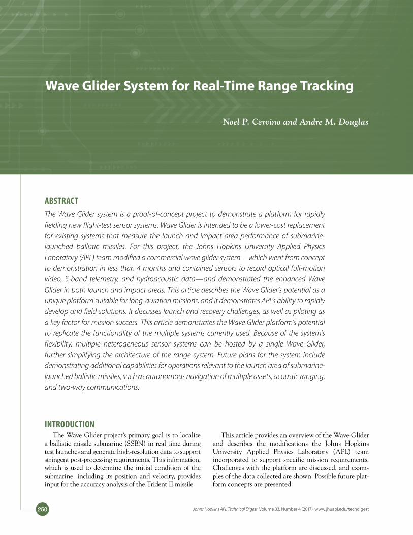
As shown in Fig. 1, three major components make up the Wave Glider: the sur-face float, the subsurface glider, and the tow fish that are connected by an umbilical and tow cable. The float contains a modular payload bay for the command and control unit (CCU), auxiliary power units, and end-user equipment. The CCU and auxiliary power units contain lithium ion batteries for long-term energy stor-age; they are recharged by solar panels attached to the surface of the float. Various masts and antennas are also mounted on the deck for communication, position-ing, and weather monitoring. The float contains a recovery buoy that is ejected from the aft end of the float to ease recovery of the system.
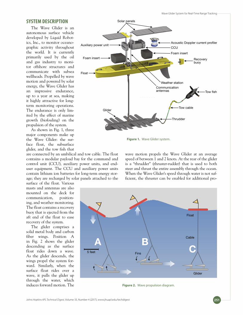
The glider comprises a solid metal body and carbon fiber wings. Position A in Fig. 2 shows the glider descending as the surface float rides down a wave. As the glider descends, the wings propel the system for-ward. Similarly, when the surface float rides over a wave, it pulls the glider up through the water, which induces forward motion. The
wave motion propels the Wave Glider at an average speed of between 1 and 2 knots. At the rear of the glider is a “thrudder” (thruster-rudder) that is used to both steer and thrust the entire assembly through the ocean. When the Wave Glider’s speed through water is not suf-ficient, the thruster can be enabled for additional pro-
Solar panels
CCU
Recoverybuoy
Tow �sh
Tow cableGlider
Thrudder
Float
Communication antennas
Weather station
Foam insert
Foam insert
Auxiliary power unitAcoustic Doppler current pro�ler
Figure 1. Wave Glider system.
Float
Cable
Glider
Fins5 feet
A BC
Figure 2. Wave propulsion diagram.
N. P. Cervino and A. M. Douglas
Johns Hopkins APL Technical Digest, Volume 33, Number 4 (2017), www.jhuapl.edu/techdigest252
pulsion, as shown by position C in Fig. 2. Currents have a significant impact on the Wave Glider’s speed through water because of the Wave Glider’s relatively low speed. When large currents are encountered, the thruster can be used to maintain control of the Wave Glider.
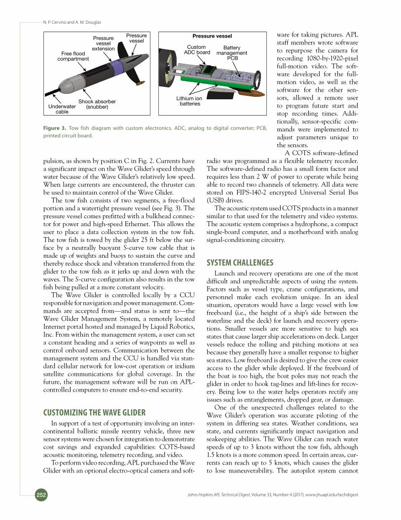
The tow fish consists of two segments, a free-flood portion and a watertight pressure vessel (see Fig. 3). The pressure vessel comes prefitted with a bulkhead connec-tor for power and high-speed Ethernet. This allows the user to place a data collection system in the tow fish. The tow fish is towed by the glider 25 ft below the sur-face by a neutrally buoyant S-curve tow cable that is made up of weights and buoys to sustain the curve and thereby reduce shock and vibration transferred from the glider to the tow fish as it jerks up and down with the waves. The S-curve configuration also results in the tow fish being pulled at a more constant velocity.
The Wave Glider is controlled locally by a CCU responsible for navigation and power management. Com-mands are accepted from—and status is sent to—the Wave Glider Management System, a remotely located Internet portal hosted and managed by Liquid Robotics, Inc. From within the management system, a user can set a constant heading and a series of waypoints as well as control onboard sensors. Communication between the management system and the CCU is handled via stan-dard cellular network for low-cost operation or iridium satellite communications for global coverage. In the future, the management software will be run on APL-controlled computers to ensure end-to-end security.
CUSTOMIZING THE WAVE GLIDERIn support of a test of opportunity involving an inter-
continental ballistic missile reentry vehicle, three new sensor systems were chosen for integration to demonstrate cost savings and expanded capabilities: COTS-based acoustic monitoring, telemetry recording, and video.
To perform video recording, APL purchased the Wave Glider with an optional electro-optical camera and soft-
ware for taking pictures. APL staff members wrote software to repurpose the camera for recording 1080-by-1920-pixel full-motion video. The soft-ware developed for the full-motion video, as well as the software for the other sen-sors, allowed a remote user to program future start and stop recording times. Addi-tionally, sensor-specific com-mands were implemented to adjust parameters unique to the sensors.
A COTS software-defined radio was programmed as a flexible telemetry recorder. The software-defined radio has a small form factor and requires less than 2 W of power to operate while being able to record two channels of telemetry. All data were stored on FIPS-140-2 encrypted Universal Serial Bus (USB) drives.
The acoustic system used COTS products in a manner similar to that used for the telemetry and video systems. The acoustic system comprises a hydrophone, a compact single-board computer, and a motherboard with analog signal-conditioning circuitry.
SYSTEM CHALLENGESLaunch and recovery operations are one of the most
difficult and unpredictable aspects of using the system. Factors such as vessel type, crane configurations, and personnel make each evolution unique. In an ideal situation, operators would have a large vessel with low freeboard (i.e., the height of a ship’s side between the waterline and the deck) for launch and recovery opera-tions. Smaller vessels are more sensitive to high sea states that cause larger ship accelerations on deck. Larger vessels reduce the rolling and pitching motions at sea because they generally have a smaller response to higher sea states. Low freeboard is desired to give the crew easier access to the glider while deployed. If the freeboard of the boat is too high, the boat poles may not reach the glider in order to hook tag-lines and lift-lines for recov-ery. Being low to the water helps operators rectify any issues such as entanglements, dropped gear, or damage.
One of the unexpected challenges related to the Wave Glider’s operation was accurate piloting of the system in differing sea states. Weather conditions, sea state, and currents significantly impact navigation and seakeeping abilities. The Wave Glider can reach water speeds of up to 3 knots without the tow fish, although 1.5 knots is a more common speed. In certain areas, cur-rents can reach up to 5 knots, which causes the glider to lose maneuverability. The autopilot system cannot
Pressurevessel
extension
Pressurevessel
Free �oodcompartment
Underwatercable
Shock absorber(snubber)
Pressure vessel
Custom ADC board
Battery management
PCB
Lithium ion batteries
Figure 3. Tow fish diagram with custom electronics. ADC, analog to digital converter; PCB, printed circuit board.

Wave Glider System for Real-Time Range Tracking
Johns Hopkins APL Technical Digest, Volume 33, Number 4 (2017), www.jhuapl.edu/techdigest 253
handle situations like this, requiring the operator to use ship-handling techniques to mitigate backward or drift motion. In addition, sea state affects the system propul-sion needs. When the sea state is high, the water speed of the system is also high. When the sea state is low, the system will have a low water speed, requiring the use of the thruster. Because the thruster endurance depends on system battery capacity and weather patterns, spe-cifically the solar radiation, the operators have to bal-ance the use of the thruster and sea propulsion carefully to maintain control of the glider. Although maintaining this balance is difficult, the operators have successfully demonstrated the ability to navigate these conditions on multiple occasions.
IMPACT AREA SUPPORT TESTING
While the primary mis-sion of the Wave Glider is to augment existing flight-test instrumentation in the launch area, there are use cases in the impact area as well. The APL
team’s first use of the Wave Glider demonstrated the sensor platform’s ability to record a reentry body’s impact acoustics, terminal area telemetry, and terminal area video (see Fig. 4). Although the initial test used a single Wave Glider to demonstrate the capability, a system capa-ble of geolocating a reentry body’s impact location would use multiple Wave Gliders positioned around the impact area to record acoustic samples from each Wave Glider’s hydrophone near the time of impact. With known Wave Glider positions and accurate data time tagging, properly designed time difference of arrival algorithms can be used to determine the impact location accurately.
The APL team had the opportunity to operate the Wave Glider in the impact area of an Air Force inter-continental ballistic missile test, Glory Trip 213, as a complete demonstration of the system’s capabilities. The Wave Glider was deployed 20 nmi south of the impact area and moved north over the course of 2 days to a posi-tion where it loitered 3 nmi from the projected impact location. After the team received confirmation of a posi-tive launch, recording times were sent via satellite com-munications to the Wave Glider, configuring it to record data from each of its three sensors (acoustic, telemetry, and video) during the impact. All three sensor systems successfully recorded data. After impact, the Wave Glider transited south 20 nmi and held station while awaiting retrieval. Considering the short development time, this test was extremely successful, demonstrating the APL team’s ability to pilot the Wave Glider and use it to record a diverse set of data useful for performance scoring in the impact area.
Figure 5 shows the reentry vehicle’s impact. Two and a half seconds after impact, a bottom-reflected echo was detected, which is consistent with water depth of 3800 m. The periodic interference visible in the time series was caused by the water speed sensor and is being corrected for future tests.
Figure 4. Impact area concept.
GT 213 acoustic time series
Time (normalized)
No
rmal
ized
ful
l-sc
ale
mag
nitu
de
–0.8
–0.2
0.6
0.4
0.2
0
–0.4
–0.6
0.8
0 0.1 0.2 0.3 0.4 0.5 0.9 1.00.80.70.6
Figure 5. Acoustic data.
N. P. Cervino and A. M. Douglas
Johns Hopkins APL Technical Digest, Volume 33, Number 4 (2017), www.jhuapl.edu/techdigest254
between the SSBN and the Wave Glider. Each Wave Glider is equipped with an Automatic Identification System receiver. The Automatic Identification System is used on larger vessels to indicate position, heading, and speed for collision avoidance. The Wave Glider would be able to transmit these surface contacts to the SSBN to increase situational awareness. Additionally, the satel-lite communications systems on the Wave Glider would provide a redundant all-purpose communications link to the WCQ2/6 underwater telephone.
Future system capabilities will lead to increased reli-ability and coverage. Using information shared from the SSBN, the Wave Glider could track the location of the SSBN. With local communication links, each Wave Glider would know the position of the other Wave Glid-ers. With this information, the Wave Gliders could oper-ate autonomously and cooperatively to track the SSBN. Also, the Wave Gliders would work autonomously to ensure that the units are positioned to allow communi-cation between the SSBN and the requisite number of Wave Gliders.
High-definition (1920 × 1080 pixel) video was recorded from the camera at 30 frames per second. As shown in Fig. 6, the reentry vehicle is clearly visible during the last few seconds before impact. While the electro-optical camera provided a demonstration capa-bility within the tight development time line, the APL team is examining other camera types that would be more effective in this environment.
LAUNCH AREA SUPPORT TESTINGDuring a second testing event, the Wave Glider was
deployed in the launch area during the Trident II Dem-onstration and Shakedown Operation 26 (DASO-26) missile test to determine the distance at which the Wave Glider can acoustically receive specially designed test signals from the SSBN. These signals are typically used to activate bottom-mounted deep-ocean transponders used for geolocating the SSBN during a missile launch.
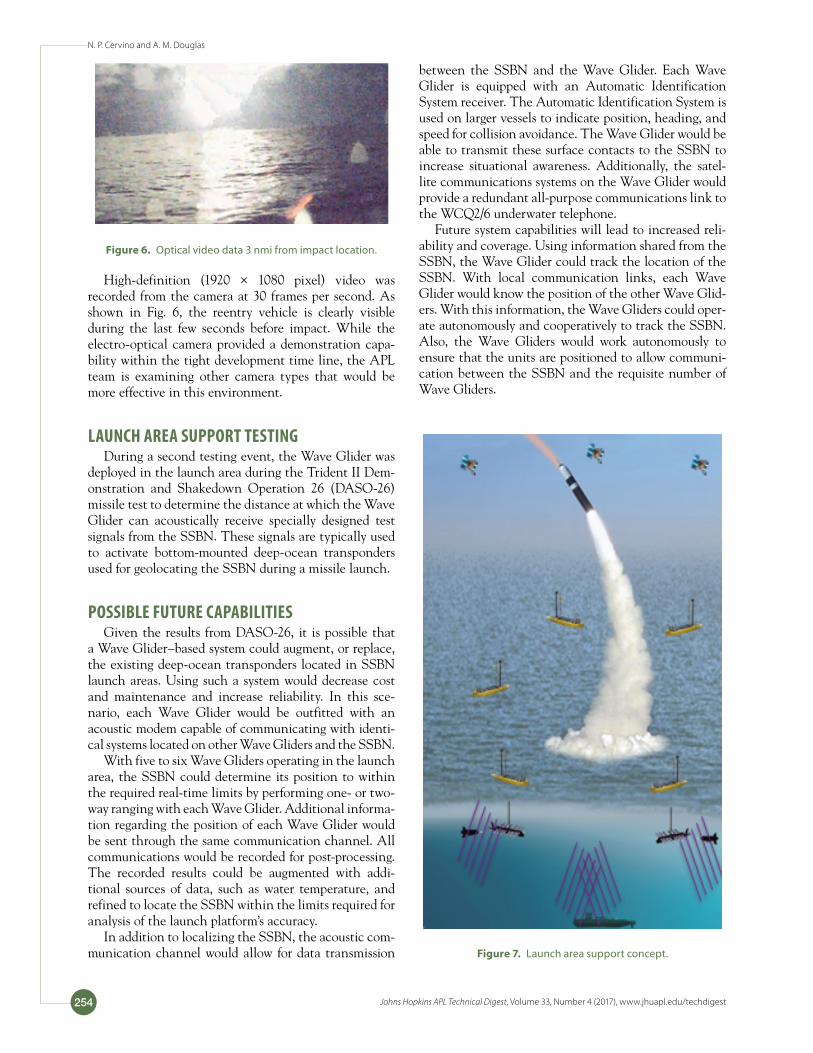
POSSIBLE FUTURE CAPABILITIESGiven the results from DASO-26, it is possible that
a Wave Glider–based system could augment, or replace, the existing deep-ocean transponders located in SSBN launch areas. Using such a system would decrease cost and maintenance and increase reliability. In this sce-nario, each Wave Glider would be outfitted with an acoustic modem capable of communicating with identi-cal systems located on other Wave Gliders and the SSBN.
With five to six Wave Gliders operating in the launch area, the SSBN could determine its position to within the required real-time limits by performing one- or two-way ranging with each Wave Glider. Additional informa-tion regarding the position of each Wave Glider would be sent through the same communication channel. All communications would be recorded for post-processing. The recorded results could be augmented with addi-tional sources of data, such as water temperature, and refined to locate the SSBN within the limits required for analysis of the launch platform’s accuracy.
In addition to localizing the SSBN, the acoustic com-munication channel would allow for data transmission
Figure 6. Optical video data 3 nmi from impact location.
Figure 7. Launch area support concept.
Wave Glider System for Real-Time Range Tracking
Johns Hopkins APL Technical Digest, Volume 33, Number 4 (2017), www.jhuapl.edu/techdigest 255
Noel P. Cervino, Force Projection Sector, Johns Hopkins University Applied Physics Laboratory, Laurel, MD
Noel P. Cervino is a senior electrical engi-neer in APL’s Force Projection Sector. He earned a bachelor’s degree in electrical engineering from the University of Mary-land and a master’s degree in electrical
engineering from Johns Hopkins University. He is the Lead Engineer for the Wave Glider project, overseeing all of the design and testing. He joined APL in 2010 and has spent the last 6 years designing embedded systems for autonomous vehi-cles and high-rate data collection, specifically for missile telem-etry and global navigation satellite system post-processing. His e-mail address is [email protected].
Andre M. Douglas, Force Projection Sector, Johns Hopkins University Applied Physics Laboratory, Laurel, MD
Andre M. Douglas is a senior mechanical engineer in APL’s Force Projection Sector. He earned a bachelor’s degree in mechani-cal engineering from the U.S. Coast Guard Academy and dual M.S.E. degrees in
mechanical engineering and naval architecture/marine engi-neering from the University of Michigan. He was responsible for the design, fabrication, integration, and testing of the Wave Glider’s sensor and physical mounting structure, in addition to executing challenging piloting operations. His current posi-tion at APL involves rapid prototyping, systems integration, and trade study analysis. As a former active-duty officer in the Coast Guard, Andre served in various roles involving sea operations, shipboard engineering, and maritime technical analysis. Andre’s past research and publishing efforts related to carbon fiber plate patching techniques for marine structures and maritime safety engineering and integration topics, while his current research interests include renewable energy con-cepts and remote sensing applications. His e-mail address is [email protected].