watt's up & doc wattson watt meter and power analyzer user ...€¦ · "watt's...
TRANSCRIPT

Revision 1.7 9/1/2007
"Watt's Up" & "Doc Wattson" Watt Meter and Power Analyzer User's Manual
Model WU100 v2
*** Please visit our website for the latest version of this manual ***

Notices
"Watt's Up" & "Doc Wattson" Watt Meter and Power Analyzer User's Manual RC Electronics, Inc.
Copyright
Copyright © 2004-2007 by RC Electronics, Inc.. All rights reserved. No part of this manual may be reproduced or transmitted in any form or by an means, analog, digital, electronic or mechanical, including imaging, photocopying and recording, for any purpose other than the purchaser's personal use without the written permission of RC Electronics, Inc., 2980 E. Capitol Expy. #50-194, San Jose, CA 95148.
Trademarks
Watt's Up and Doc Wattson are trademarks of RC Electronics, Inc..
All other brand and product names mentioned in this manual are trademarks or registered trademarks of their respective owners.
Changes
The material in this manual is for information only and is subject to change without notice. While reasonable efforts have been made in the preparation of this manual to ensure its accuracy, RC Electronics, Inc. assumes no liability resulting from errors or omissions in this manual, or from the use of information contained herein.
RC Electronics, Inc. reserves the right to make changes in the product design without reservation and without notification to its users.
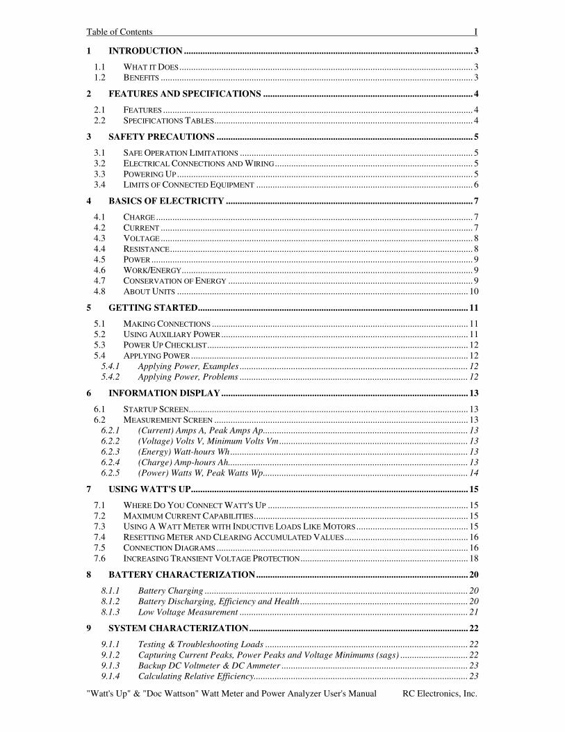
Table of Contents I
"Watt's Up" & "Doc Wattson" Watt Meter and Power Analyzer User's Manual RC Electronics, Inc.
1 INTRODUCTION ............................................................................................................................ 3 1.1 WHAT IT DOES .............................................................................................................................. 3 1.2 BENEFITS ...................................................................................................................................... 3
2 FEATURES AND SPECIFICATIONS .......................................................................................... 4 2.1 FEATURES ..................................................................................................................................... 4 2.2 SPECIFICATIONS TABLES............................................................................................................... 4
3 SAFETY PRECAUTIONS .............................................................................................................. 5 3.1 SAFE OPERATION LIMITATIONS .................................................................................................... 5 3.2 ELECTRICAL CONNECTIONS AND WIRING ..................................................................................... 5 3.3 POWERING UP ............................................................................................................................... 5 3.4 LIMITS OF CONNECTED EQUIPMENT ............................................................................................. 6
4 BASICS OF ELECTRICITY .......................................................................................................... 7 4.1 CHARGE ........................................................................................................................................ 7 4.2 CURRENT ...................................................................................................................................... 7 4.3 VOLTAGE ...................................................................................................................................... 8 4.4 RESISTANCE.................................................................................................................................. 8 4.5 POWER .......................................................................................................................................... 9 4.6 WORK/ENERGY............................................................................................................................. 9 4.7 CONSERVATION OF ENERGY ......................................................................................................... 9 4.8 ABOUT UNITS ............................................................................................................................. 10
5 GETTING STARTED.................................................................................................................... 11 5.1 MAKING CONNECTIONS .............................................................................................................. 11 5.2 USING AUXILIARY POWER .......................................................................................................... 11 5.3 POWER UP CHECKLIST................................................................................................................ 12 5.4 APPLYING POWER ....................................................................................................................... 12
5.4.1 Applying Power, Examples .................................................................................................. 12 5.4.2 Applying Power, Problems .................................................................................................. 12
6 INFORMATION DISPLAY.......................................................................................................... 13 6.1 STARTUP SCREEN........................................................................................................................ 13 6.2 MEASUREMENT SCREEN ............................................................................................................. 13
6.2.1 (Current) Amps A, Peak Amps Ap........................................................................................ 13 6.2.2 (Voltage) Volts V, Minimum Volts Vm................................................................................. 13 6.2.3 (Energy) Watt-hours Wh...................................................................................................... 13 6.2.4 (Charge) Amp-hours Ah....................................................................................................... 13 6.2.5 (Power) Watts W, Peak Watts Wp........................................................................................ 14
7 USING WATT'S UP....................................................................................................................... 15 7.1 WHERE DO YOU CONNECT WATT'S UP ...................................................................................... 15 7.2 MAXIMUM CURRENT CAPABILITIES............................................................................................ 15 7.3 USING A WATT METER WITH INDUCTIVE LOADS LIKE MOTORS ................................................ 15 7.4 RESETTING METER AND CLEARING ACCUMULATED VALUES ..................................................... 16 7.5 CONNECTION DIAGRAMS ............................................................................................................ 16 7.6 INCREASING TRANSIENT VOLTAGE PROTECTION........................................................................ 18
8 BATTERY CHARACTERIZATION........................................................................................... 20 8.1.1 Battery Charging ................................................................................................................. 20 8.1.2 Battery Discharging, Efficiency and Health ........................................................................ 20 8.1.3 Low Voltage Measurement .................................................................................................. 21
9 SYSTEM CHARACTERIZATION.............................................................................................. 22 9.1.1 Testing & Troubleshooting Loads ....................................................................................... 22 9.1.2 Capturing Current Peaks, Power Peaks and Voltage Minimums (sags) ............................. 22 9.1.3 Backup DC Voltmeter & DC Ammeter ................................................................................ 23 9.1.4 Calculating Relative Efficiency............................................................................................ 23
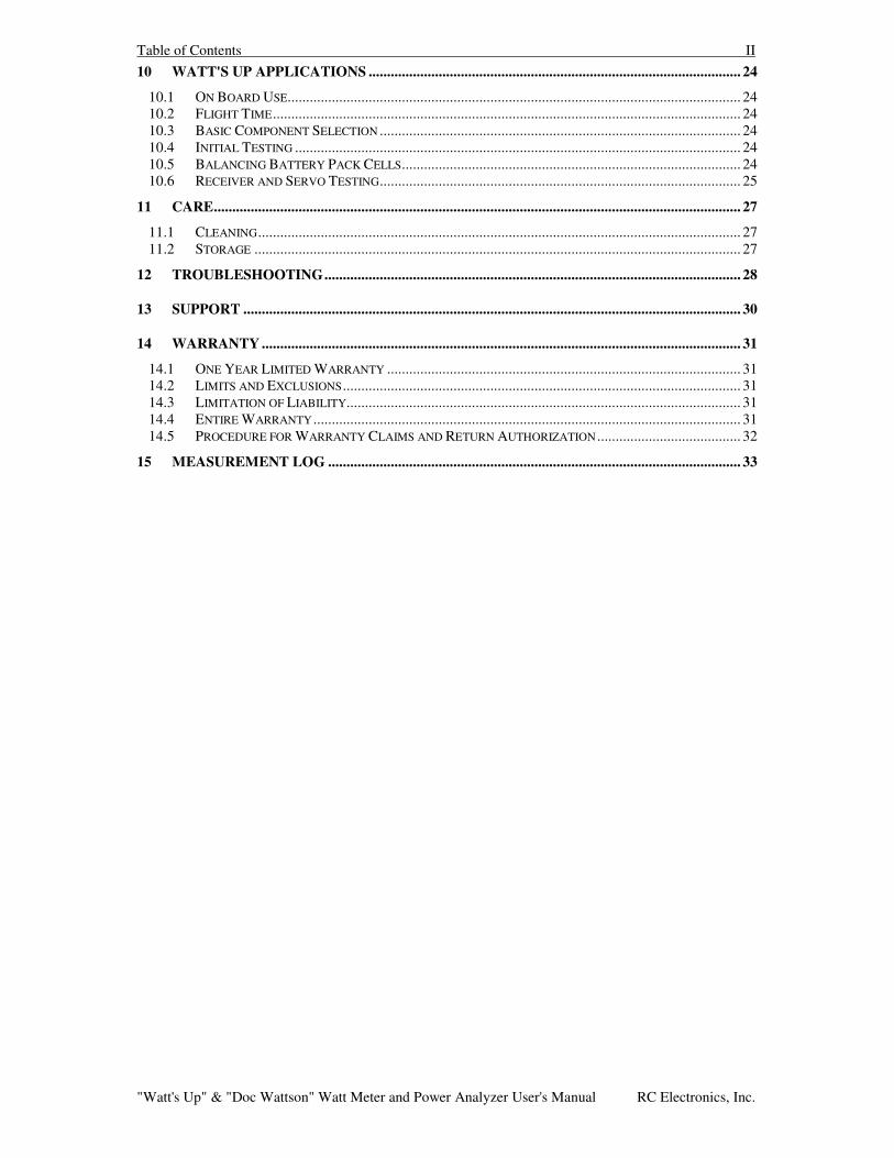
Table of Contents II
"Watt's Up" & "Doc Wattson" Watt Meter and Power Analyzer User's Manual RC Electronics, Inc.
10 WATT'S UP APPLICATIONS ..................................................................................................... 24 10.1 ON BOARD USE........................................................................................................................... 24 10.2 FLIGHT TIME............................................................................................................................... 24 10.3 BASIC COMPONENT SELECTION .................................................................................................. 24 10.4 INITIAL TESTING ......................................................................................................................... 24 10.5 BALANCING BATTERY PACK CELLS............................................................................................ 24 10.6 RECEIVER AND SERVO TESTING.................................................................................................. 25
11 CARE............................................................................................................................................... 27 11.1 CLEANING................................................................................................................................... 27 11.2 STORAGE .................................................................................................................................... 27
12 TROUBLESHOOTING................................................................................................................. 28
13 SUPPORT ....................................................................................................................................... 30
14 WARRANTY .................................................................................................................................. 31 14.1 ONE YEAR LIMITED WARRANTY ................................................................................................ 31 14.2 LIMITS AND EXCLUSIONS............................................................................................................ 31 14.3 LIMITATION OF LIABILITY........................................................................................................... 31 14.4 ENTIRE WARRANTY .................................................................................................................... 31 14.5 PROCEDURE FOR WARRANTY CLAIMS AND RETURN AUTHORIZATION ....................................... 32
15 MEASUREMENT LOG ................................................................................................................ 33
Introduction 3
"Watt's Up" & "Doc Wattson" Watt Meter and Power Analyzer User's Manual RC Electronics, Inc.
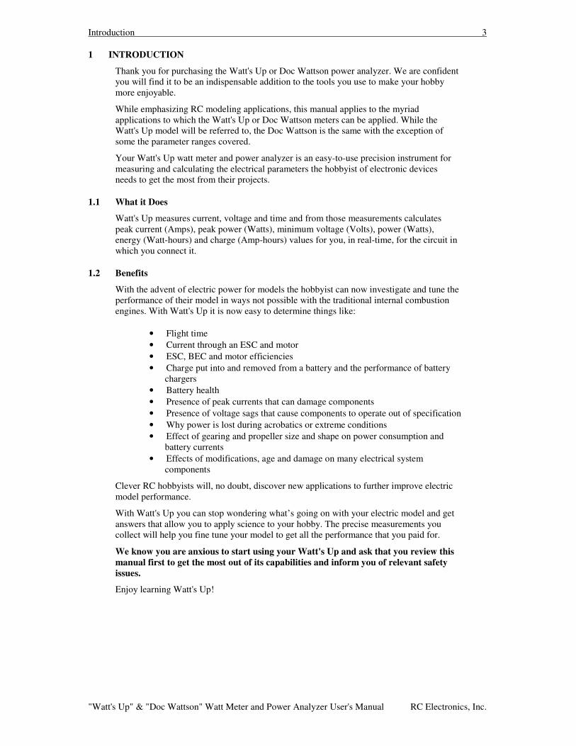
1 INTRODUCTION
Thank you for purchasing the Watt's Up or Doc Wattson power analyzer. We are confident you will find it to be an indispensable addition to the tools you use to make your hobby more enjoyable.
While emphasizing RC modeling applications, this manual applies to the myriad applications to which the Watt's Up or Doc Wattson meters can be applied. While the Watt's Up model will be referred to, the Doc Wattson is the same with the exception of some the parameter ranges covered.
Your Watt's Up watt meter and power analyzer is an easy-to-use precision instrument for measuring and calculating the electrical parameters the hobbyist of electronic devices needs to get the most from their projects.
1.1 What it Does
Watt's Up measures current, voltage and time and from those measurements calculates peak current (Amps), peak power (Watts), minimum voltage (Volts), power (Watts), energy (Watt-hours) and charge (Amp-hours) values for you, in real-time, for the circuit in which you connect it.
1.2 Benefits
With the advent of electric power for models the hobbyist can now investigate and tune the performance of their model in ways not possible with the traditional internal combustion engines. With Watt's Up it is now easy to determine things like:
• Flight time • Current through an ESC and motor • ESC, BEC and motor efficiencies • Charge put into and removed from a battery and the performance of battery
chargers • Battery health • Presence of peak currents that can damage components • Presence of voltage sags that cause components to operate out of specification • Why power is lost during acrobatics or extreme conditions • Effect of gearing and propeller size and shape on power consumption and
battery currents • Effects of modifications, age and damage on many electrical system
components
Clever RC hobbyists will, no doubt, discover new applications to further improve electric model performance.
With Watt's Up you can stop wondering what’s going on with your electric model and get answers that allow you to apply science to your hobby. The precise measurements you collect will help you fine tune your model to get all the performance that you paid for.
We know you are anxious to start using your Watt's Up and ask that you review this manual first to get the most out of its capabilities and inform you of relevant safety issues.
Enjoy learning Watt's Up!
Features and Specifications 4
"Watt's Up" & "Doc Wattson" Watt Meter and Power Analyzer User's Manual RC Electronics, Inc.
2 FEATURES AND SPECIFICATIONS
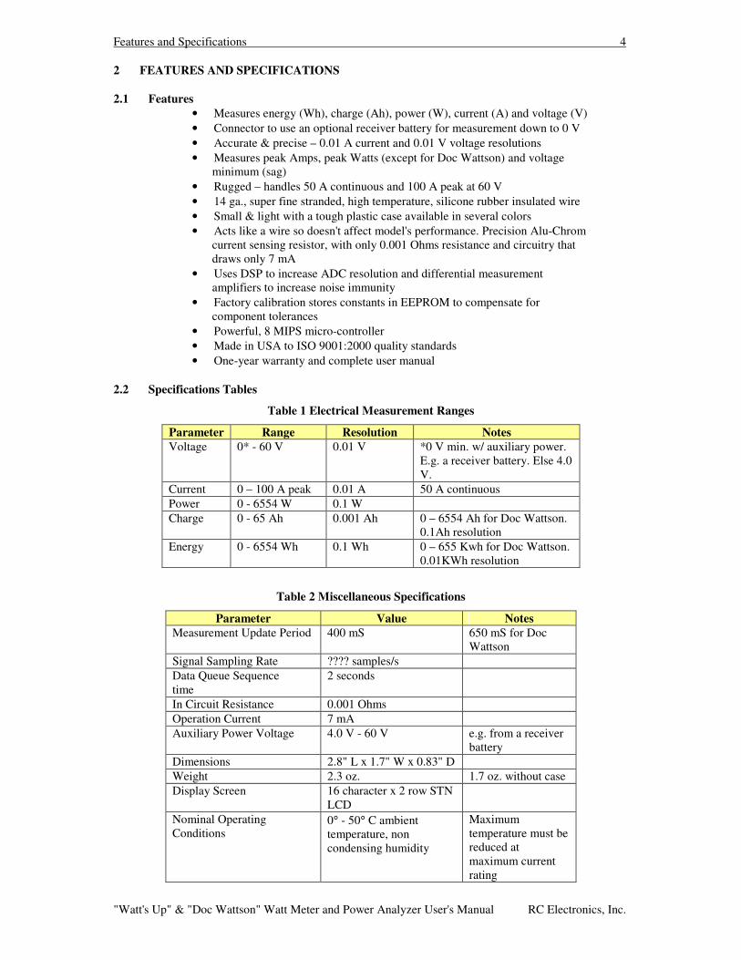
2.1 Features • Measures energy (Wh), charge (Ah), power (W), current (A) and voltage (V) • Connector to use an optional receiver battery for measurement down to 0 V • Accurate & precise – 0.01 A current and 0.01 V voltage resolutions • Measures peak Amps, peak Watts (except for Doc Wattson) and voltage
minimum (sag) • Rugged – handles 50 A continuous and 100 A peak at 60 V • 14 ga., super fine stranded, high temperature, silicone rubber insulated wire • Small & light with a tough plastic case available in several colors • Acts like a wire so doesn't affect model's performance. Precision Alu-Chrom
current sensing resistor, with only 0.001 Ohms resistance and circuitry that draws only 7 mA
• Uses DSP to increase ADC resolution and differential measurement amplifiers to increase noise immunity
• Factory calibration stores constants in EEPROM to compensate for component tolerances
• Powerful, 8 MIPS micro-controller • Made in USA to ISO 9001:2000 quality standards • One-year warranty and complete user manual
2.2 Specifications Tables
Table 1 Electrical Measurement Ranges
Parameter Range Resolution Notes Voltage 0* - 60 V 0.01 V *0 V min. w/ auxiliary power.
E.g. a receiver battery. Else 4.0 V.
Current 0 – 100 A peak 0.01 A 50 A continuous Power 0 - 6554 W 0.1 W Charge 0 - 65 Ah 0.001 Ah 0 – 6554 Ah for Doc Wattson.
0.1Ah resolution Energy 0 - 6554 Wh 0.1 Wh 0 – 655 Kwh for Doc Wattson.
0.01KWh resolution
Table 2 Miscellaneous Specifications
Parameter Value Notes Measurement Update Period 400 mS 650 mS for Doc
Wattson Signal Sampling Rate ???? samples/s Data Queue Sequence time
2 seconds
In Circuit Resistance 0.001 Ohms Operation Current 7 mA Auxiliary Power Voltage 4.0 V - 60 V e.g. from a receiver
battery Dimensions 2.8" L x 1.7" W x 0.83" D Weight 2.3 oz. 1.7 oz. without case Display Screen 16 character x 2 row STN
LCD
Nominal Operating Conditions
0° - 50° C ambient temperature, non condensing humidity
Maximum temperature must be reduced at maximum current rating
Safety Precautions 5
"Watt's Up" & "Doc Wattson" Watt Meter and Power Analyzer User's Manual RC Electronics, Inc.
3 SAFETY PRECAUTIONS
CAUTION: High power electrical systems pose dangers independent of devices like the Watt's Up and it is the user's responsibility to be familiar with these dangers and take any necessary action to ensure safe use. Shorting a rechargeable battery or a Watt's Up connected to a rechargeable battery or battery charger can supply huge currents and have serious consequences including explosions, causing fire, damage to equipment and personal injury.
Please carefully read the entire SAFTY PRECAUTIONS section to ensure safe product use.
3.1 Safe Operation Limitations
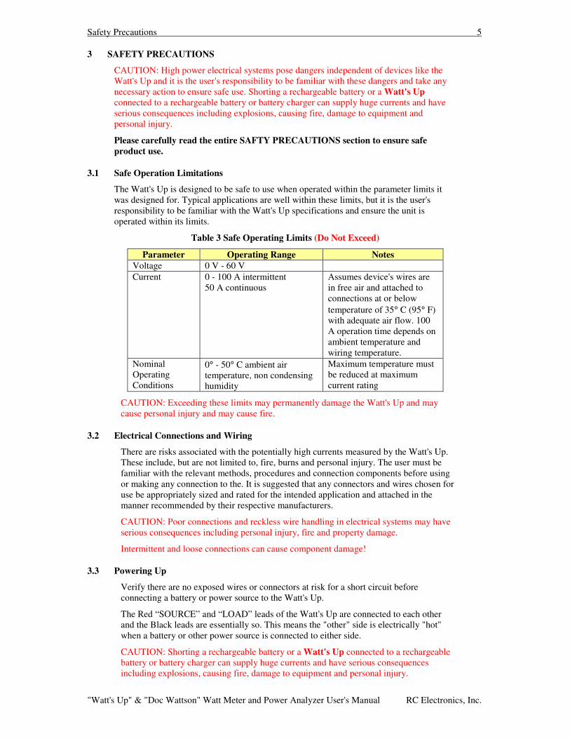
The Watt's Up is designed to be safe to use when operated within the parameter limits it was designed for. Typical applications are well within these limits, but it is the user's responsibility to be familiar with the Watt's Up specifications and ensure the unit is operated within its limits.
Table 3 Safe Operating Limits (Do Not Exceed)
Parameter Operating Range Notes Voltage 0 V - 60 V Current 0 - 100 A intermittent
50 A continuous Assumes device's wires are in free air and attached to connections at or below temperature of 35° C (95° F) with adequate air flow. 100 A operation time depends on ambient temperature and wiring temperature.
Nominal Operating Conditions
0° - 50° C ambient air temperature, non condensing humidity
Maximum temperature must be reduced at maximum current rating
CAUTION: Exceeding these limits may permanently damage the Watt's Up and may cause personal injury and may cause fire.
3.2 Electrical Connections and Wiring
There are risks associated with the potentially high currents measured by the Watt's Up. These include, but are not limited to, fire, burns and personal injury. The user must be familiar with the relevant methods, procedures and connection components before using or making any connection to the. It is suggested that any connectors and wires chosen for use be appropriately sized and rated for the intended application and attached in the manner recommended by their respective manufacturers.
CAUTION: Poor connections and reckless wire handling in electrical systems may have serious consequences including personal injury, fire and property damage.
Intermittent and loose connections can cause component damage!
3.3 Powering Up
Verify there are no exposed wires or connectors at risk for a short circuit before connecting a battery or power source to the Watt's Up.
The Red “SOURCE” and “LOAD” leads of the Watt's Up are connected to each other and the Black leads are essentially so. This means the "other" side is electrically "hot" when a battery or other power source is connected to either side.
CAUTION: Shorting a rechargeable battery or a Watt's Up connected to a rechargeable battery or battery charger can supply huge currents and have serious consequences including explosions, causing fire, damage to equipment and personal injury.
Safety Precautions 6
"Watt's Up" & "Doc Wattson" Watt Meter and Power Analyzer User's Manual RC Electronics, Inc.
3.4 Limits of Connected Equipment
The Watt's Up may have measurement capabilities, operating ratings and electrical signal handling abilities that exceed those of equipment to which it is connected. This means the Watt's Up may be able to make measurements on a connected component despite that component being operated outside of its safe operating ratings.
CAUTION: It is the user's responsibility to consider the limitations of any equipment connected to the Watt's Up and not to exceed them since the Watt's Up provides no protection for those components. Examples of possible hazards include, without limitation: charging or discharging batteries outside their voltage and current ratings, application of excessive voltage or currents to electronic speed controls (ESC) and motors, application of currents that cause dangerous heating or voltages that present a shock hazard. Other hazards may exist.

Basics of Electricity 7
"Watt's Up" & "Doc Wattson" Watt Meter and Power Analyzer User's Manual RC Electronics, Inc.
4 BASICS OF ELECTRICITY
Understanding the basics of electricity will help you get the most out of your Watt's Up and electric model. With these concepts you can intelligently compare electrical components and conduct experiments to maximize their performance in your electric modeling hobby.
If you are new to electrical propulsion systems you may want to read through this a few times. Experts can skip it.
We use the water and plumbing analogies to teach electrical concepts because people often already have good intuition about water systems.
4.1 Charge
It all starts with charge.
Charge is the basic unit of electric energy. Using the water analogy, charge is the “amount of water”.
Charge (electrons actually) is what gets stored in a rechargeable battery by a battery charger. Like water gets “stored” in an aquarium by a water pump a battery charger stores charge in a battery.
Asking how much charge is in a battery is like asking how much water is in an aquarium.
A physicist will tell you that charge is measured in units of Coulombs (C) like water can be measured in units of gallons. It turns out that Amp-hours (Ah) is also a unit of charge and is more familiar to RC hobbyists. We’ll show why later when we discuss current.
Charge = Current × Time.
Charge can be measured in Amp-Hours by:
Amp-hours = Average Amps × hours of duration
4.2 Current
Current is measured as an amount of something flowing per unit of time.
With electricity, the “something” flowing in a wire is charge, which is measured in “Coulombs”.
A Coulomb per second of electric charge current has a special name. It is called an Ampere (abbreviated Amps or just A). A gallon per second of water flow doesn’t have a special name. It’s just a gal/s.
So 20 Amperes or Amps flowing into a motor means it has a current of 20 Coulombs of charge flowing per second.
Now we can explain why Amp-Hours is a measure of charge.
An hour is 60 × 60 = 3600 seconds. So an Amp-hour (meaning Amps times hours)
= Ampere × Hour
And substituting the definition of an Ampere and of an hour this becomes
= (Coulomb/Second) × 3600 Seconds which leaves 3600 Coulombs.
Coulombs are charge so there we are -- an Amp-hour (or Ah) is 3600 Coulombs of charge.
It is common in RC modeling to discuss charge in units of mAh. The m is an abbreviation for the Greek “milli” which means “thousandth” of something. So 1 mAh is 1/1000 of an Ah. Conversely, 2 Ah is the same as 2000 mAh.
Here are some examples showing the important relationships between current, time and charge.
1) Charging.

Basics of Electricity 8
"Watt's Up" & "Doc Wattson" Watt Meter and Power Analyzer User's Manual RC Electronics, Inc.
If you pump 1 gal/h of water into an aquarium for five hours it will contain 1 gal/h × 5 h = 5 gallons. Similarly a battery charging at 1500 mA for one hour will contain 1.5 Amp × one hour = 1.5 Ah of charge. Since we learned above that there are 3600 Coulombs per Ah, the physicist would say the battery contains 1.5 Ah × 3600 C/Ah = 5400 Coulombs of charge. Amp-hr versus C. They are different ways of saying the same thing.
2) Discharging
If you know a battery and an aquarium are both “full” you just read their “capacity” (volume) specification to find the stored “charge.” The aquarium says 20 gallons and the battery says 2000 mAh. The aquarium would take 4 hours to empty at a “current” of 5 gal/h and the battery would take 1 hour to empty at a current of 2000 mA.
4.3 Voltage
Something forces current to flow in a wire. That something is called voltage and is measured in Volts (abbreviated V). The pressure your hand feels pushing water out of a pipe is the force analogous to voltage.
You can’t get a current without a voltage. The two are related by the concept of resistance.
4.4 Resistance
Resistance is measured in Ohms (abbreviated with the Greek symbol Omega Ω). It is the property that limits the current, which flows in a wire for a given voltage applied across the wire.
The very important “Ohm’s Law” summarizes this relationship.
Amps = Volts ÷ Ohms
It says the amount of current depends on the voltage applied divided by the amount of resistance. Push harder for a given amount of resistance and you get more flow.
Reducing the diameter of a water pipe increases its resistance and therefore reduces the water flowing from it for a given pressure (voltage). Similarly doubling the resistance of a wire halves the current flowing through it for a given voltage across it.
A useful thing to remember is that 1 Volt divided by 1 Ohm = 1 Amp.
It says that One Amp of current will flow in wire having a resistance of one Ohm if one Volt of voltage is applied across it.
So given relatively fixed battery voltages, you need low resistance wires to allow high currents.
Resistance is a general term for a rather complex phenomenon. There are different kinds of resistance. For our purposes we will mean Direct Current or DC resistance. Alternating Current or AC resistance is beyond the scope of this tutorial and is not widely discussed in RC electrical systems.
Here’s an example problem using resistance.
How much voltage drop is there to a motor drawing 50 Amps if the motor is one foot from the battery? Assume14 Ga. wire has a resistance of approximately 0.0025 Ohms per foot.
So we have two feet of wire total with 50 Amps flowing through them. Ohms law tells us that to get 50 Amps through a wire of 2 × 0.0025 Ohms requires:
Volts = Amps × Ohms, = 50 × (2 × 0.0025) = 0.25 V.
So those wires use up 0.25 V in battery voltage. Our motor would receive 7.15 Volts from a 7.4 Volt battery. Apparently, this motor consumes exactly 50 Amps at exactly 7.15 V.
Basics of Electricity 9
"Watt's Up" & "Doc Wattson" Watt Meter and Power Analyzer User's Manual RC Electronics, Inc.
4.5 Power
Power is measured in units of Watts.
A key concept:
Power is the rate at which work is done or energy is expended and not the amount of work done.
Or:
Power = energy ÷ time
The power being delivered or used (in Watts) is measured by the current (in Amps) multiplied by the voltage (in Volts) of the system being measured. I.E.
Watts = Amps × Volts
A battery has a fixed energy capacity or amount of work it can do. The rate at which it does that work or dumps that energy is its power output and that power output can be varied by the time over which the work is done.
For example, the work or energy a battery and motor do to roll an electric car up a 30 foot hill is the same whether it takes a minute or an hour to do so. The power, however, is 60 times greater in the second case!
Using the water analogy, you might fill a 10,000-gallon water tank (representing a fixed amount of work/energy to be done) in two days with a small electric water pump. It would take a pump attached to a “very powerful” V8 gas engine with a supercharger to fill it in five minutes. Both need the same energy, but require very different powers. The difference is the time the effort takes.
4.6 Work/Energy
From a physics point of view, work and energy describe the same thing. The word chosen at a particular time depends on the point of view being emphasized by an author. Hopefully, this will become clear as you read on.
People often, incorrectly, mix the concepts of power and energy/work as though they are the same. They are different, but related by time. Understanding the difference is very important toward an understanding of propulsion system performance.
Voltage does work to move charge. The battery charger worked to push charge against the battery’s voltage into the battery. That work is stored as charge in the battery. Discharging the battery does work on whatever is using the charge.
This work or energy is measured in Watt-hours by measuring the power (in Watts) expended over some time duration (in hours).
Watt-hours = Watts (averaged) × hours
This is how much work the electricity has done.
The energy stored in a battery depends on the product of charge and voltage. I.E.
Energy (Wh) = voltage (V) × charge (Ah)
So while a 7.4 V and 14.8 V battery pack may both have the same charge of 2000 mAh, the 14.8 V pack has twice the energy and capacity to do work.
4.7 Conservation of Energy
This is a very important physics concept that will help you evaluate electric model power systems.
Simply stated, conservation of energy means that energy isn't ever lost; rather it has gone someplace "else."
Energy has many forms, Heat, Kinetic, Potential and Chemical being the most relevant to RC.
Basics of Electricity 10
"Watt's Up" & "Doc Wattson" Watt Meter and Power Analyzer User's Manual RC Electronics, Inc.
Two examples will help.
1) If you discharge a battery pack into light bulbs the energy stored in the battery's chemistry was converted to heat in the battery's chemical reaction the wiring and the light bulb filaments.
2) In an electric motor powered plane, energy from the battery converts to heat energy in wires, connectors, the electronic components in the Electronic Speed Control, the wires in the motor armature, the brushes, the motor bearings and lubricant and the air the prop and plane fly through AND to potential energy that has been stored by the height the plane's mass is above the ground AND to kinetic energy stored in the speed of the plane's mass.
If you measured all the heat generated and other stored energies, it would equal that previously stored in the battery. That's the conservation.
Inefficiency in a process like this means some energy went someplace you didn't want it to like the wires, bearings, ESC and brushes. You wanted it all delivered to the prop.
In battery charging, energy from the charger is delivered as a current into a battery where it is converted to a charge stored in the battery's chemistry. In a perfect rechargeable battery no energy would go anyplace else. In reality it does, like to heat, so battery charging is not 100 % efficient.
What you can learn from all of this is that your options for an electric powered model's capabilities must consider all the places energy will be used.
Learning some basic things about potential and kinetic energy as well as Newton's second Law of motion in a simple physics text book will give you powerful tools to evaluate an electric model capabilities.
4.8 About Units
Small amounts of current and voltage are usually measured in milliamps or millivolts where “milli” is a Greek abbreviation meaning “one thousandth of.” For example, 10 mA means ten – one thousandths of one Amp, which is written as 0.01 Amps. 1000 mA is another way to write 1 A. Similarly, 0.001 V is one thousandth of one volt. Milli is a widely used prefix. E.g. 3000 mAh is another way to write a charge of 3 Ah.

Information Display 11
"Watt's Up" & "Doc Wattson" Watt Meter and Power Analyzer User's Manual RC Electronics, Inc.
5 GETTING STARTED
Please be familiar with the contents of the SAFETY PRECAUTIONS section before continuing.
5.1 Making Connections
Watt's Up is supplied without connectors so you can use whatever kind you prefer.
Always connect and disconnect power at the meter FIRST on whichever of the LOAD or SOURCE sides that has the highest electrical inductance. This is usually at the LOAD. Long wire runs, motors, generators, etc. can have considerable inductance.
If you attach connectors to the SOURCE and LOAD leads that mate with those you use on your models it will be easier to do testing with your Watt's Up. However, it is strongly recommended that you only use female connectors on batteries and other power sources to prevent connectors and bare metal contacts from shorting together.
For example, with female (socket) connectors on your battery you will want male (plug) connectors on the Watt's Up SOURCE leads and female connectors on the Watt's Up LOAD leads. With this configuration, the Watt's Up can be inserted, like jumper cables, between the battery and a load such as a ESC with Motor.
The user is responsible for selecting connectors rated to handle the current and voltage expected in the user’s application and to follow the instructions provided with the connectors to ensure best results.
Only qualified individuals should assemble any high current connections.
The Red SOURCE wire goes to Positive (Plus +) battery or other device terminals and black to Negative (Minus -).
Warning: Loose and intermittent connections can cause component damage!
5.2 Using Auxiliary Power
By connecting a receiver battery pack (of at least 4.0 V) or other power source to the 3-pin connector on the SOURCE side, the Watt's Up can measure down to 0 V. This makes it possible to measure the characteristics of a single battery cell.
The 3-pin connector’s socket will accept a Futaba J type, JR or HiTec type servo plug connector. A suitable connector with wires attached is available for purchase from our website.
Pin 1 is Negative (0 Volts), pin 2 (middle pin) is Positive. Pin 1 is the pin farthest from the Watt's Up SOURCE wires. Pin 3, on meter versions 2.1 and above, is for reset of accumulated readings. See below for description of reset operation.
When using Auxiliary power, you may see small measurement values when the SOURCE and LOAD leads have nothing connected or are shorted together. It is neither unusual nor a problem for there to be small values displayed in this situation. This will not affect performance when making real measurements.
The Watt's Up has been optimized to provide highest performance for real measurements of connected power systems and loads, but with all leads unconnected may produce erroneous readings. With real connections, accurate readings will be produced. Note that shorting the SOURCE leads together and/or the LOAD leads together may show a very small voltage (e.g. 0.01 Volts). These small “shorted lead” voltages are well within specification and don't affect the accuracy of real measurements.
Caution: Never short leads for testing with a power source connected to either set of leads!

Information Display 12
"Watt's Up" & "Doc Wattson" Watt Meter and Power Analyzer User's Manual RC Electronics, Inc.
5.3 Power Up Checklist
We recommend you always go through this checklist before applying power to the Watt's Up.
• Always verify there are no exposed wires or bare connectors that can short circuit prior to connecting a battery or power source to the Watt's Up.
• Carefully inspect wire and connector insulation for damage or bare spots that can short. Properly insulate any such areas with electrical tape or shrink tubing.
• While a load connection is not required, ensuring that the LOAD wires are safely routed is important to prevent shorts. Capping unused connectors with a fully insulated mating connector as a "cap" is a useful trick. E.g. capping a female connector with an insulated male connector.
CAUTION: Verify correct connection polarities before applying power or damage may result!
5.4 Applying Power
The Watt's Up requires a power source providing a minimum of 4.0 V to operate. This can come from a power source (battery or charger) on the LOAD or SOURCE side or from the auxiliary 3-pin SOURCE power input connector.
If you connect an auxiliary power source of 4.0 V or more (e.g. small receiver battery pack), the Watt's Up operates independently of power sources on the LOAD or SOURCE leads. This allows measurements down to 0V, e.g. for measuring a single cell main pack.
Note that, for example, a standard 9 V alkaline battery can be wired to an auxiliary connector and cable to be used as an auxiliary battery if desired.
5.4.1 Applying Power, Examples • Use at least a four cell NiCd or NiMH battery pack or a two cell Li-Poly
battery pack on the SOURCE side to provide the minimum 4.0 V. Connect a load on the LOAD side. E.g an ESC and a MOTOR.
• Connect an Auxiliary power source to the 3-pin SOURCE power input connector and a single Li-Poly cell to the SOURCE side and an ESC and motor to the LOAD side.
5.4.2 Applying Power, Problems
When you apply power as described, the Watt's Up display will show the "Startup Screen" and then begin measurements.
CAUTION: if the Startup Screen does not appear, immediately remove the power sources and refer to the troubleshooting section of this document.
Information Display 13
"Watt's Up" & "Doc Wattson" Watt Meter and Power Analyzer User's Manual RC Electronics, Inc.
6 INFORMATION DISPLAY
6.1 Startup Screen
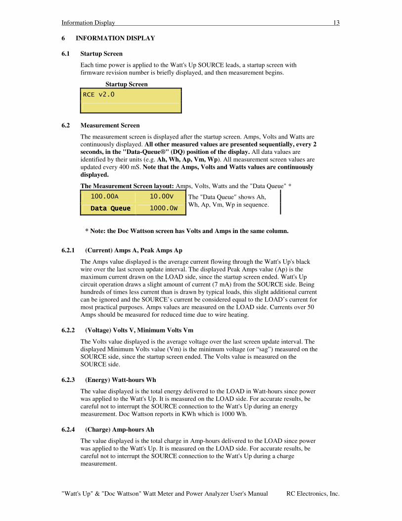
Each time power is applied to the Watt's Up SOURCE leads, a startup screen with firmware revision number is briefly displayed, and then measurement begins.
Startup Screen
6.2 Measurement Screen
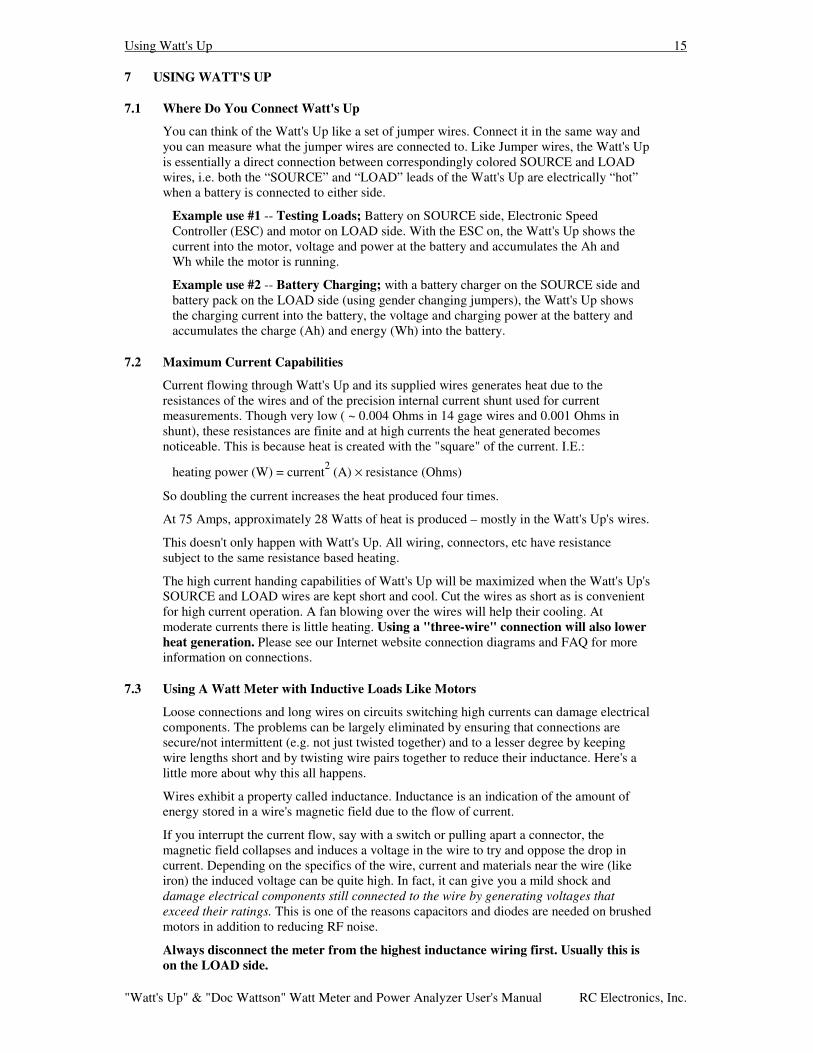
The measurement screen is displayed after the startup screen. Amps, Volts and Watts are continuously displayed. All other measured values are presented sequentially, every 2 seconds, in the "Data-Queue®" (DQ) position of the display. All data values are identified by their units (e.g. Ah, Wh, Ap, Vm, Wp). All measurement screen values are updated every 400 mS. Note that the Amps, Volts and Watts values are continuously displayed.
The Measurement Screen layout: Amps, Volts, Watts and the "Data Queue" *
The "Data Queue" shows Ah, Wh, Ap, Vm, Wp in sequence.
* Note: the Doc Wattson screen has Volts and Amps in the same column.
6.2.1 (Current) Amps A, Peak Amps Ap
The Amps value displayed is the average current flowing through the Watt's Up's black wire over the last screen update interval. The displayed Peak Amps value (Ap) is the maximum current drawn on the LOAD side, since the startup screen ended. Watt's Up circuit operation draws a slight amount of current (7 mA) from the SOURCE side. Being hundreds of times less current than is drawn by typical loads, this slight additional current can be ignored and the SOURCE’s current be considered equal to the LOAD’s current for most practical purposes. Amps values are measured on the LOAD side. Currents over 50 Amps should be measured for reduced time due to wire heating.
6.2.2 (Voltage) Volts V, Minimum Volts Vm
The Volts value displayed is the average voltage over the last screen update interval. The displayed Minimum Volts value (Vm) is the minimum voltage (or “sag”) measured on the SOURCE side, since the startup screen ended. The Volts value is measured on the SOURCE side.
6.2.3 (Energy) Watt-hours Wh
The value displayed is the total energy delivered to the LOAD in Watt-hours since power was applied to the Watt's Up. It is measured on the LOAD side. For accurate results, be careful not to interrupt the SOURCE connection to the Watt's Up during an energy measurement. Doc Wattson reports in KWh which is 1000 Wh.
6.2.4 (Charge) Amp-hours Ah
The value displayed is the total charge in Amp-hours delivered to the LOAD since power was applied to the Watt's Up. It is measured on the LOAD side. For accurate results, be careful not to interrupt the SOURCE connection to the Watt's Up during a charge measurement.

Information Display 14
"Watt's Up" & "Doc Wattson" Watt Meter and Power Analyzer User's Manual RC Electronics, Inc.
6.2.5 (Power) Watts W, Peak Watts Wp
The value displayed is the average power delivered in Watts over the last screen update interval. The displayed Peak Watts value (Wp) is the maximum power drawn on the LOAD side, since the startup screen ended. Watts values are measured on the LOAD side.
Using Watt's Up 15
"Watt's Up" & "Doc Wattson" Watt Meter and Power Analyzer User's Manual RC Electronics, Inc.
7 USING WATT'S UP
7.1 Where Do You Connect Watt's Up
You can think of the Watt's Up like a set of jumper wires. Connect it in the same way and you can measure what the jumper wires are connected to. Like Jumper wires, the Watt's Up is essentially a direct connection between correspondingly colored SOURCE and LOAD wires, i.e. both the “SOURCE” and “LOAD” leads of the Watt's Up are electrically “hot” when a battery is connected to either side.
Example use #1 -- Testing Loads; Battery on SOURCE side, Electronic Speed Controller (ESC) and motor on LOAD side. With the ESC on, the Watt's Up shows the current into the motor, voltage and power at the battery and accumulates the Ah and Wh while the motor is running.
Example use #2 -- Battery Charging; with a battery charger on the SOURCE side and battery pack on the LOAD side (using gender changing jumpers), the Watt's Up shows the charging current into the battery, the voltage and charging power at the battery and accumulates the charge (Ah) and energy (Wh) into the battery.
7.2 Maximum Current Capabilities
Current flowing through Watt's Up and its supplied wires generates heat due to the resistances of the wires and of the precision internal current shunt used for current measurements. Though very low ( ~ 0.004 Ohms in 14 gage wires and 0.001 Ohms in shunt), these resistances are finite and at high currents the heat generated becomes noticeable. This is because heat is created with the "square" of the current. I.E.:
heating power (W) = current2 (A) × resistance (Ohms)
So doubling the current increases the heat produced four times.
At 75 Amps, approximately 28 Watts of heat is produced – mostly in the Watt's Up's wires.
This doesn't only happen with Watt's Up. All wiring, connectors, etc have resistance subject to the same resistance based heating.
The high current handing capabilities of Watt's Up will be maximized when the Watt's Up's SOURCE and LOAD wires are kept short and cool. Cut the wires as short as is convenient for high current operation. A fan blowing over the wires will help their cooling. At moderate currents there is little heating. Using a "three-wire" connection will also lower heat generation. Please see our Internet website connection diagrams and FAQ for more information on connections.
7.3 Using A Watt Meter with Inductive Loads Like Motors
Loose connections and long wires on circuits switching high currents can damage electrical components. The problems can be largely eliminated by ensuring that connections are secure/not intermittent (e.g. not just twisted together) and to a lesser degree by keeping wire lengths short and by twisting wire pairs together to reduce their inductance. Here's a little more about why this all happens.
Wires exhibit a property called inductance. Inductance is an indication of the amount of energy stored in a wire's magnetic field due to the flow of current.
If you interrupt the current flow, say with a switch or pulling apart a connector, the magnetic field collapses and induces a voltage in the wire to try and oppose the drop in current. Depending on the specifics of the wire, current and materials near the wire (like iron) the induced voltage can be quite high. In fact, it can give you a mild shock and damage electrical components still connected to the wire by generating voltages that exceed their ratings. This is one of the reasons capacitors and diodes are needed on brushed motors in addition to reducing RF noise.
Always disconnect the meter from the highest inductance wiring first. Usually this is on the LOAD side.
Using Watt's Up 16
"Watt's Up" & "Doc Wattson" Watt Meter and Power Analyzer User's Manual RC Electronics, Inc.
7.4 Resetting Meter and Clearing Accumulated Values
All accumulated readings including Ah, Wh, peak current, etc. can be reset to zero in one of two ways.
1. Completely remove all voltage from the Source's Red AND the Auxiliary Connector's Pin 2 or,
2. On meter versions 2.1 and above, briefly (e.g. a thousandth of a second) connecting the Auxiliary Connector's pin 3 to zero Volts. E.g. pin 1 or the meter's black wire. Meter versions prior to version 2.1 do not have the Pin 3 reset capability.
Note that the meter will be held reset and not function if the reset signal (pin 3) is continuously connected.
Pin 1 is the pin farthest from the Watt's Up SOURCE wires. Pin 3 is nearest the SOURCE wires.
Pin 3 has a 3.3K Ohms input impedance.
See diagrams below to understand the reset function connections.
7.5 Connection Diagrams
The following diagrams show example connections between the Watt's Up and various Sources and Loads using a "four-wire" connection.
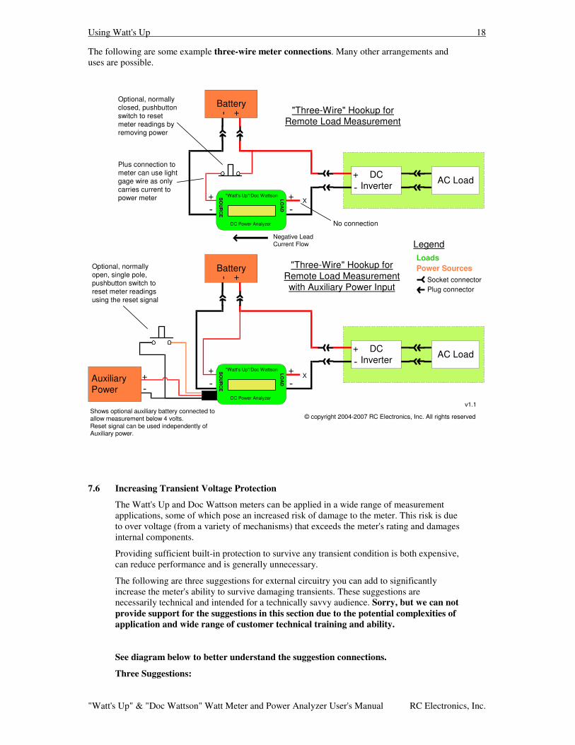
A "three-wire" connection only connects the meter's red (plus) lead at the LOAD or the SOURCE, but not both. A separate wire must be present to make the SOURCE to LOAD (e.g. battery to speed control) connection "around" the meter. The advantage of the three-wire connection is that only the meter's black wires must carry current and therefore be heavy and that the heat generated in the meter is reduced since there is only low current in the red voltage sense wire to the meter.
An example three-wire hookup is shown in the diagram for reset and transient voltage protection further on in this document.
Generally, the three-wire connection is the highest performance and is recommended. The four-wire "jumper cable" approach can be easier to understand and may simplify connector usage.
Please see our Internet website connection diagrams and FAQ for additional information on making connections.

Using Watt's Up 17
"Watt's Up" & "Doc Wattson" Watt Meter and Power Analyzer User's Manual RC Electronics, Inc.
The following are some example four-wire meter connections. Many other arrangements and uses are possible.
Testing Loads(e.g. motors)
"Watt's Up"
watt meter
Battery(4-60 V)*
+-
+-
SpeedControl
+-
+-
Motor(Brushed orBrushless)
BatteryCharger(4-60 V)*
Battery+-
+-
+-
SO
UR
CE
LOA
D
"Watt's Up"
watt meter
+-
+-
SO
UR
CE
LOA
D
plug - plugjumper wires
"Watt's Up"
watt meter
Battery(0-60 V)
+-
+-
DischargeLoad
+-
+-
SO
UR
CE
LOA
D
Battery Charging
Battery DischargingLoadsPower Sources
Legend
Plug connectorSocket connector
AuxiliaryBattery(4-60 V)
+-
Shows auxiliary battery connected toallow measurement down to 0 volts
* 0 V if using auxiliary battery.
"Watt's Up"
watt meter
ReceiverBattery
(e.g. 4.8 V)
+-
+-
+-
Receiver+-
SO
UR
CE
LOA
D
Receiver & ServoTesting
AuxiliaryBattery(4-60 V)
+-
.
.
.
Servo n
Servo 1
your adapter /jumper wires
v1.1
Using Watt's Up 18
"Watt's Up" & "Doc Wattson" Watt Meter and Power Analyzer User's Manual RC Electronics, Inc.
The following are some example three-wire meter connections. Many other arrangements and uses are possible.
LoadsPower Sources
Legend
Plug connectorSocket connector
"Three-Wire" Hookup forRemote Load Measurementwith Auxiliary Power Input
+-
+-
SO
UR
CE
LOA
D
DCInverter
+-
AC Load"Watt's Up"/Doc Wattson
DC Power Analyzer
Battery+-
AuxiliaryPower
Shows optional auxiliary battery connected toallow measurement below 4 volts.Reset signal can be used independently ofAuxiliary power.
"Three-Wire" Hookup forRemote Load Measurement
+-
+-
SO
UR
CE
LOA
D
No connection
Plus connection tometer can use lightgage wire as onlycarries current topower meter
DCInverter
+-
AC Load"Watt's Up"/Doc Wattson
DC Power Analyzer
Battery+-
Negative LeadCurrent Flow
Optional, normallyclosed, pushbuttonswitch to resetmeter readings byremoving power
© copyright 2004-2007 RC Electronics, Inc. All rights reserved
Optional, normallyopen, single pole,pushbutton switch toreset meter readingsusing the reset signal
X
X
v1.1
+-
7.6 Increasing Transient Voltage Protection
The Watt's Up and Doc Wattson meters can be applied in a wide range of measurement applications, some of which pose an increased risk of damage to the meter. This risk is due to over voltage (from a variety of mechanisms) that exceeds the meter's rating and damages internal components.
Providing sufficient built-in protection to survive any transient condition is both expensive, can reduce performance and is generally unnecessary.
The following are three suggestions for external circuitry you can add to significantly increase the meter's ability to survive damaging transients. These suggestions are necessarily technical and intended for a technically savvy audience. Sorry, but we can not provide support for the suggestions in this section due to the potential complexities of application and wide range of customer technical training and ability.
See diagram below to better understand the suggestion connections.
Three Suggestions:

Using Watt's Up 19
"Watt's Up" & "Doc Wattson" Watt Meter and Power Analyzer User's Manual RC Electronics, Inc.
1. Use a transient voltage suppression (TVS) zener diode across meter's leads. Add an appropriate unidirectional transient voltage suppressor (TVS) zener diode like a "Transorb" with the "cathode" side on the meter's plus (red) lead and the other end on the negative <black) lead. The TVS cathode end usually has a band. Make sure the TVS turn on voltage is above that of the voltage being measured, but it's clamp voltage is below that of the meter's max rating. A higher Joule/power/energy rating is better, other things being equal.
As an example, the Diodes Inc. partnumber: 1.5KE43A (which Digi-Key carries) is a unidirectional ~ 43 Volt turn on, 1500 Watt TVS Zener diode with axial leads that clamps voltages to less than 60V. It would not be appropriate in circuits having measured voltages near or greater than 43 Volts because it would start shorting them out at ~ 43 Volts.
This approach does not affect meter accuracy, but does limit the maximum applied voltage to somewhat less than the TVS diode's turn on voltage.
2. Use auxiliary power and add series resistor to measured voltage. Power the meter using the Auxiliary Connector connected to a voltage source that exceeds by one volt the voltage to be measured by the meter. E.g 13V to the auxiliary connector if measuring a 12V power source. Connect the voltage to be measured to the plus lead of the meter via a non wirewound (they're inductive) resistor with a value of at least 270 Ohms and power rating of ¼ Watt or more. A 274 Ohm resistor adds ~ -0.1% error (will read low) to voltage (not current) measurements. Higher resistance increases protection, but at increased voltage error. E.g. a 1.3K Ohm which increases voltage error to ~ -0.5%. Digi-Key carries the inexpensive Yageo, MFR series metal film resistors (e.g. pn: MFR-25FBF-274R) which will work as will many others. The Auxiliary power source must be free of voltage transients itself. It can be connected through a resistor as well as long as the IR voltage drop from the ~7 mA meter operating current results in voltage at the meter that still exceeds the voltage being measured. E.g. a 270 Ohm resistor would require a minimum 15 Volt source due to the (270 X 0.007) 1.9 V drop across the resistor.
Failure to provide sufficiently high Auxiliary voltage will result in the meter being powered by the measured voltage. Any added resistor will then add an IR voltage drop error to measured readings. E.g. ~1.9V using a 274 Ohm resistor.
3. Remove internal power sharing diode. *** This is an Absolutely unsupported modification – don't even think of getting support for this or making a warranty claim on a meter whose case has been opened ***. With the case open, carefully remove diode D1. Once done, this will require powering the meter through the Auxiliary Connector, but will also make the meter more robust against overvoltage transients and remove the requirement that, to be the sole power source, the Auxiliary Connector voltage must exceed the measured SOURCE voltage.
The following diagram shows components added to increase transient voltage protection as well as the use of a pushbutton switch to reset meter readings.
LoadsPower Sources
Legend
Plug connectorSocket connector
MeasuredPowerSource
Load+-
"Three Wire" Hookup showingtransient protection components and
reset switch connection
meter
+-
SO
UR
CE
LOA
D
X
Make noconnection
AuxiliaryPowerSource
+-
Optional,normally open,single pole,pushbuttonswitch to resetmeter readings
TVS
ProtectionResistor
+-
+
-
cathode end
Negative LeadCurrent Flow
© copyright 2004-2007 RC Electronics, Inc. All rights reserved
Battery Characterization 20
"Watt's Up" & "Doc Wattson" Watt Meter and Power Analyzer User's Manual RC Electronics, Inc.
8 BATTERY CHARACTERIZATION
8.1.1 Battery Charging
You can monitor the current, accumulated charge and energy into and voltage on a charging battery.
Connect the Watt's Up as shown in the "Battery Charging" CONNECTION DIAGRAM. You made need gender-changing connectors/wiring to do this depending on the connectors you are using. Follow the manufacturer instructions for operation of the charger and battery.
Note that the Watt's Up's Peak Amps, Peak Watts and Voltage Minimum values are cleared whenever the Watt's Up turns on. If the battery is connected before the charger is turned on, the Watt's Up will track the minimum voltage on the battery during the charging process.
With the charger on and the battery charging, the Watt's Up displays the ongoing charging electrical values. The current (As) and power (W) show the average rate of charge and the voltage indicates the current battery charging voltage.
CAUTION: When charging a battery do not operate it outside its manufacturer's specifications. For example, do not allow battery voltage to exceed the maximum value specified or charge at a current that exceeds the maximum specified or charge at a temperature or manner that violates the manufacturers specifications. Note that so-called "Battery Zapping Devices" may generate voltages and currents that exceed the safe operating limits of both Watt's Up and batteries. Do not leave a charging battery unattended.
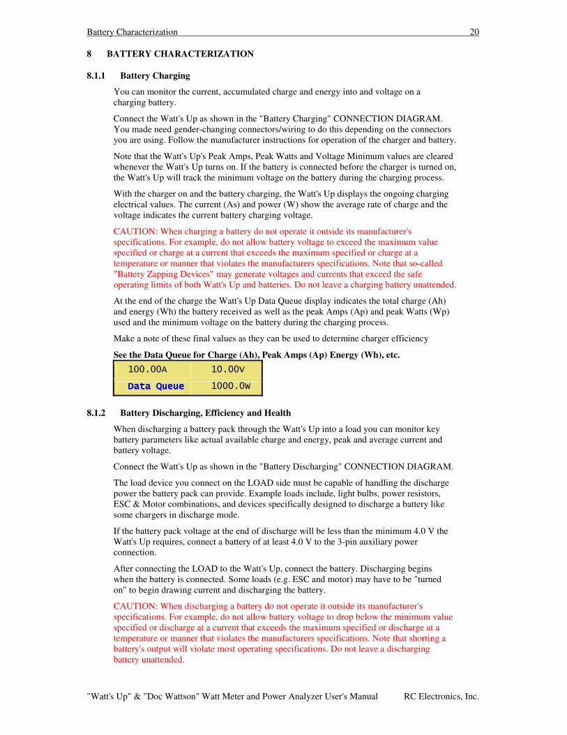
At the end of the charge the Watt's Up Data Queue display indicates the total charge (Ah) and energy (Wh) the battery received as well as the peak Amps (Ap) and peak Watts (Wp) used and the minimum voltage on the battery during the charging process.
Make a note of these final values as they can be used to determine charger efficiency
See the Data Queue for Charge (Ah), Peak Amps (Ap) Energy (Wh), etc.
8.1.2 Battery Discharging, Efficiency and Health
When discharging a battery pack through the Watt's Up into a load you can monitor key battery parameters like actual available charge and energy, peak and average current and battery voltage.
Connect the Watt's Up as shown in the "Battery Discharging" CONNECTION DIAGRAM.
The load device you connect on the LOAD side must be capable of handling the discharge power the battery pack can provide. Example loads include, light bulbs, power resistors, ESC & Motor combinations, and devices specifically designed to discharge a battery like some chargers in discharge mode.
If the battery pack voltage at the end of discharge will be less than the minimum 4.0 V the Watt's Up requires, connect a battery of at least 4.0 V to the 3-pin auxiliary power connection.
After connecting the LOAD to the Watt's Up, connect the battery. Discharging begins when the battery is connected. Some loads (e.g. ESC and motor) may have to be "turned on" to begin drawing current and discharging the battery.
CAUTION: When discharging a battery do not operate it outside its manufacturer's specifications. For example, do not allow battery voltage to drop below the minimum value specified or discharge at a current that exceeds the maximum specified or discharge at a temperature or manner that violates the manufacturers specifications. Note that shorting a battery's output will violate most operating specifications. Do not leave a discharging battery unattended.
Battery Characterization 21
"Watt's Up" & "Doc Wattson" Watt Meter and Power Analyzer User's Manual RC Electronics, Inc.
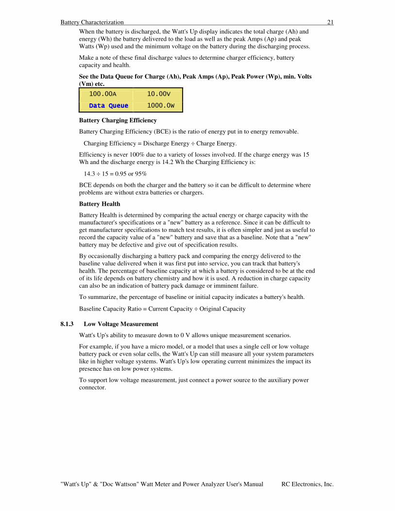
When the battery is discharged, the Watt's Up display indicates the total charge (Ah) and energy (Wh) the battery delivered to the load as well as the peak Amps (Ap) and peak Watts (Wp) used and the minimum voltage on the battery during the discharging process.
Make a note of these final discharge values to determine charger efficiency, battery capacity and health.
See the Data Queue for Charge (Ah), Peak Amps (Ap), Peak Power (Wp), min. Volts (Vm) etc.
Battery Charging Efficiency
Battery Charging Efficiency (BCE) is the ratio of energy put in to energy removable.
Charging Efficiency = Discharge Energy ÷ Charge Energy.
Efficiency is never 100% due to a variety of losses involved. If the charge energy was 15 Wh and the discharge energy is 14.2 Wh the Charging Efficiency is:
14.3 ÷ 15 = 0.95 or 95%
BCE depends on both the charger and the battery so it can be difficult to determine where problems are without extra batteries or chargers.
Battery Health
Battery Health is determined by comparing the actual energy or charge capacity with the manufacturer's specifications or a "new" battery as a reference. Since it can be difficult to get manufacturer specifications to match test results, it is often simpler and just as useful to record the capacity value of a "new" battery and save that as a baseline. Note that a "new" battery may be defective and give out of specification results.
By occasionally discharging a battery pack and comparing the energy delivered to the baseline value delivered when it was first put into service, you can track that battery's health. The percentage of baseline capacity at which a battery is considered to be at the end of its life depends on battery chemistry and how it is used. A reduction in charge capacity can also be an indication of battery pack damage or imminent failure.
To summarize, the percentage of baseline or initial capacity indicates a battery's health.
Baseline Capacity Ratio = Current Capacity ÷ Original Capacity
8.1.3 Low Voltage Measurement
Watt's Up's ability to measure down to 0 V allows unique measurement scenarios.
For example, if you have a micro model, or a model that uses a single cell or low voltage battery pack or even solar cells, the Watt's Up can still measure all your system parameters like in higher voltage systems. Watt's Up's low operating current minimizes the impact its presence has on low power systems.
To support low voltage measurement, just connect a power source to the auxiliary power connector.

System Characterization 22
"Watt's Up" & "Doc Wattson" Watt Meter and Power Analyzer User's Manual RC Electronics, Inc.
9 SYSTEM CHARACTERIZATION
9.1.1 Testing & Troubleshooting Loads
To use Watt's Up to test, measure and troubleshoot Load behavior, connect the Watt's Up and components as shown in the "Testing Loads" CONNECTION DIAGRAM. Use the auxiliary power to ensure measurements down to 0 Volts. Follow the manufacturer instructions for operation of the battery and Load components.
The object of testing & troubleshooting Loads is to confirm that all components are within their safe operating ranges, to determine what their actual operating conditions are and to uncover problems.
Example load tests are:
Does the ESC deliver the maximum allowed current to the motor?
How much current and power is delivered at various throttle settings?
Is too much current being drawn from the battery?
Is too much current or power being passed through the ESC or the motor?
Are there unexplained current peaks or voltage minimums that indicate problems or explain why the system has malfunctioned in the past?
How much charge and energy are consumed by the load, for the time and exercise performed?
The usual test procedure is to connect the Load to the LOAD side of the Watt's Up and a battery pack to the SOURCE side. While noting Watt's Up readings, exercise the system by varying things like throttle settings, gearbox ratios, motor type, ESC setup, propeller type, battery voltage and type, drive train type, etc.
Watt's Up allows you to collect precise measurements with which to make scientific performance analysis of your model.
All of the Watt's Up measured values may be useful in your Load testing & troubleshooting.
See Ah, Wh, Ap, Vm, Wp in the Data Queue
9.1.2 Capturing Current Peaks, Power Peaks and Voltage Minimums (sags)
It can be very difficult to find out why a model or a component fails. The Watt's Up ability to capture even brief current/power peaks and voltage minimum values can help.
The Peak Amps, Peaks Watts and Voltage Minimum values will be the peaks and minimum captured following the Watt's Up power on sequence. Be careful in adjusting test setups to not accidentally cause a peak or voltage minimum that isn't the one you are watching for. This might happen if, for example, you connect another component to the system while it is measuring.
The Watt's Up's Peak Amps, Peaks Watts and Voltage Minimum values are cleared whenever the Watt's Up turns on (i.e. is powered up). So remove all power sources when you need to clear them for a new measurement.
See the Ap, Vm and Wp in the Data Queue

System Characterization 23
"Watt's Up" & "Doc Wattson" Watt Meter and Power Analyzer User's Manual RC Electronics, Inc.
9.1.3 Backup DC Voltmeter & DC Ammeter
In an emergency, the Watt's Up can be used like a DC voltmeter or like a DC current meter. Remember that the Watt's Up can only measure positive voltages and currents.
Connect a battery of at least 4.0 V to the 3-pin auxiliary power connection and to nothing else. The Auxiliary power battery must be "floating electrically."
Use the SOURCE side wires for voltage measurements attaching the Red wire to voltages that are positive with respect to the Black wire. Only the display's Voltage and Volts Minimum will be accurate in this application.
To measure DC currents, connect the LOAD side Black wire to where the current comes from (more positive) and the SOURCE side Black wire to where the current is going to (less positive). Only the display's Amps and Peak Amps will be accurate in this application.
9.1.4 Calculating Relative Efficiency
The relative efficiency of two models electrical systems can be calculated and compared by using the Watt's Up in conjunction with a tachometer or other means to measure the mechanical output of each system. An example procedure for propeller propulsion models is presented.
To make efficiency measurements, you will need a tachometer or a good quality electronic fish weight scale. In order to use the tachometer method, you will keep the prop unchanged while changing other components of the system for comparison. Start by taking a baseline measurement to compare against. Run the prop up to its typical operating RPM using your tachometer and make note of the Watts reading on the Watt's Up. Now change the motor, gearbox, or other system component that you are trying to optimize. Run the prop up to the same RPM and make note of the Watts reading. The setup that is using the least Watts to run the prop at the same RPM is the most efficient.
With the fish scale method, you can change any of the system components for comparison. Mount your fish scale between a stationary object and a rolling sled that the system is mounted on. Start by taking a baseline measurement to compare against. Run the prop up to its typical operating and make note of the Watts reading on the Watt's Up and the thrust reading on the fish scale. Now change the motor, gearbox, or other system component that you are trying to optimize. Run the prop up until the fish scale reading is the same as before and make note of the Watts reading. The setup that is using the least Watts to produce same thrust is the most efficient.
Connect the Watt's Up to each system as described above. Adjust the ESC to the desired operating point (prop speed from tachometer, etc.) and make note of the Watts reading. Now connect the Watt's Up to the second system. Adjust the ESC to bring it to the same operating point. Compare the new Watts reading to the old one to determine the relative efficiency of the two systems.
Watt's Up Applications 24
"Watt's Up" & "Doc Wattson" Watt Meter and Power Analyzer User's Manual RC Electronics, Inc.
10 WATT'S UP APPLICATIONS
10.1 On Board Use
The Watt's Up is compact and lightweight compared to other Watt meters on the market. This allows the Watt's Up to be mounted on board in larger models. This can be convenient and can also allow the determination of peak Amps, peak Watts and minimum Volts while in flight due to the unique features of the Watt's Up. During short test flights, the peak Amps peak Watts and minimum Volts generally occur simultaneously under heavy load. These values can help give insight into the dynamic performance of the prop or explain erratic operation or failures.
10.2 Flight Time
You can calculate flight time at various throttle settings by taking note of the Amps reading on the Watt's Up and making some simple calculations. Divide the Ah rating of your battery pack by the Amps reading to determine the flight time in hours. If your battery pack is rated in mAh multiply the Amps reading by 1000 to convert it to mAh before dividing.
10.3 Basic Component Selection
You just finished your new model plane and want to select a battery, motor, prop, etc. Where do you start? A useful metric for initial component selection is the power to weight ratio or power loading. Power loading can be measured in watts/pound. Typical power loading ranges from 20 W/lb to 200 W/lb depending on the type of model. Park flyers and trainers are on the low end, while acrobatic and 3D models are on the high end.
Select a motor recommended for your model by the manufacture as a starting point. If the manufacture does not recommend a motor, select a motor capable of putting out the power required for a reasonable power loading for your model. Select a prop that looks suitable from the motor manufactures recommendations and the prop manufactures data. Now choose a suitable ESC and battery pack of the appropriate voltage.
10.4 Initial Testing
Now that you have chosen components to start with, it’s time to bench test things and do some tuning. Keep in mind that a prop performs differently when tested statically on a bench compared to dynamically when moving through the air. The faster a prop moves through the air, the less thrust it produces. Bench testing can help select well-matched components, but should not be taken as the final word. For bench testing, the complete system can be assembled on a rolling sled (if you want to make thrust measurements), or rigidly mounted. Connect the Watt's Up between the battery pack and the ESC.
Start by taking a baseline measurement at full throttle for comparison. Your battery pack should be fully charged for each test. Run the motor up to full throttle and make note of the Amps, Volts, and Watts readings on the Watt's Up at 30 seconds into the test then turn the motor off. Readings at the beginning of the test are not typical due to the initial punch of the batter pack, which quickly fades. The Watt's Up captures the peak Amps and peak Watts readings which you can compare to the 30 second readings to see how much initial punch your pack has.
Divide the Watts reading by the weight of your model to get the power loading. Compare this to the desired power loading for your model. Compare the Amps reading to the maximum Amps rating of your motor. If it is higher, your motor is being overloaded. If it is much lower, your motor is larger than you need for the given prop. Now change one of the system components such as the prop and run the test again. Continue this procedure until you have a well-matched system that provides the desired power loading for your model.
10.5 Balancing Battery Pack Cells
You don't want battery pack cells going below their minimum safe voltages for safety and battery life reasons.

Watt's Up Applications 25
"Watt's Up" & "Doc Wattson" Watt Meter and Power Analyzer User's Manual RC Electronics, Inc.
A battery pack whose individual cells are all balanced delivers the most energy since all cells are exhausted at the same minimum voltage. If any cell is "out of balance" it may reach the minimum safe voltage before the others and continued pack discharge will damage the cell.
If the cells in a pack all equally contribute to the overall pack voltage they are considered "in balance". So we can check each cells voltage at various states of pack charge and see if their voltages are the same. If they are, the pack is balanced. If not some individual cell reconditioning or replacement is necessary.
Cell balancing measurements need at least 0.02 volt resolution so that we can tell the difference between a 1.22 and 1.20 volt cell. More resolution is better because it allows us to recognize the lower voltage cell which will get exhausted first. The "Watt's Up" 0.01 Volt resolution is great for cell balancing where resolution is more important than accuracy. This is because we are mostly comparing our batteries to each other seeking equality rather than wanting to know what particular voltage they're at.
There are two ways to measure cell voltages.
1. Measure each cell individually
2. Measure the pack’s voltage and a few cells and subtract the cell voltages from the pack total to get the remaining cell voltage. Let's call this the "Sum and Difference Technique" - SDT for short.
The SDT is a bad approach for some very technical reasons. The short explanation is that it requires more accurate and linear voltage measurement equipment than most people have in order to prevent "quantization errors" due to digital measurement effects. A more complete explanation is beyond the scope of this user’s manual. Without that high performance equipment the value you calculate from the pack voltage minus a cell or two may be inaccurate to a degree that interferes with your cell balancing.
We, therefore, recommend you measure each cell independently. Be careful not to short out battery cells doing this.
Remember that to measure below 4 volts, the Watt's Up needs to have a battery or other power source attached to the auxiliary connector.
Protect the Watt's Up's LOAD side leads so they can't short.
After powering up, simply apply the red lead to the plus side of the battery cell being tested and the black lead to the minus side. Read the battery voltage and write it down. Repeat for all cells in the pack. Your goal is to have all the cell voltages be as equal as possible when the pack is charged and discharged. If you want to load the cells when taking measurements, you can attach the load to the LOAD leads of the Watt's Up while testing. This will also show you the load current being drawn.
10.6 Receiver and Servo Testing
A loss of receiver power can be catastrophic. This can be difficult to diagnose and troubleshoot. The most likely cause, other than bad connections, is drawing more current than the receiver battery or battery eliminator circuit can provide resulting in an unacceptably low receiver voltage. An undetected “stalled” servo is an example cause for this.
You can use the Watt's Up to determine the peak current and minimum voltage used by your receiver and servo loads and verify they are within acceptable limits over the full servo operation range.
You should use the Auxiliary power connection for doing this sort of testing because receiver operation voltage can be near the low end of the Watt's Up voltage range without it. Connecting the Auxiliary power after the SOURCE may be better for eliminating measurement of power dips immediately following SOURCE power connections. Try both before and after.

Watt's Up Applications 26
"Watt's Up" & "Doc Wattson" Watt Meter and Power Analyzer User's Manual RC Electronics, Inc.
Connect the receiver and it’s servos on the Watt's Up LOAD side and a suitable power source, e.g. your receiver battery or BEC on the SOURCE side. See the connection diagrams for an example.
Fully exercise your servos, simultaneously if possible, to create the maximum load on the battery or BEC. Monitor the peak Amps, peak Watts and minimum Volts to verify acceptable values. Unexpected peaks may be due to stalled or defective servos or linkages, etc. Remove power from both Auxiliary and SOURCE to reset the peak and minimum values.

Care 27
"Watt's Up" & "Doc Wattson" Watt Meter and Power Analyzer User's Manual RC Electronics, Inc.
11 CARE
Your Watt's Up is ruggedly constructed and requires minimal care. It contains no adjustable or field serviceable parts inside. The case is ultrasonically welded and cannot be opened without damage. Opening the case will void the warranty.
11.1 Cleaning
Do not use petroleum based solvents to clean your Watt's Up. Use a few drops of mild hand dishwashing detergent in a cup of lukewarm water. Do not apply the detergent directly to your Watt's Up. Instead, moisten a cloth with the solution and gently wipe your Watt's Up clean.
CAUTION: Do not exert too much pressure on the display! Doing so could permanently damage it.
11.2 Storage
Store your Watt's Up in a safe place where is protected from impact and scratches to the LCD display. Do not store in direct sunlight. Prolonged exposure (years) to direct sunlight will break down the plastics used in the Watt's Up.

Troubleshooting 28
"Watt's Up" & "Doc Wattson" Watt Meter and Power Analyzer User's Manual RC Electronics, Inc.
12 TROUBLESHOOTING
Problem Possible Remedies
Don't see the Startup Screen after applying power
1. Make sure the LOAD side wires are not shorted together or connected to something that is shorting them.
2. Check you have a power source (battery or charger) supplying at least 4.0 V connected to the SOURCE side wires or to the Auxiliary Power Connector.
3. Check wiring Polarity. The Red wire should be connected to the positive (Red, +, Positive, etc.) side of the power source and the Black wire to the negative side.
4. Try a 9 Volt consumer electronics type alkaline battery as the source power. If this works, your other power source is likely too low a voltage.
5. Make sure reset signal on pin 3 of Aux. connector is not connected to 0V.
Display screen characters are dim
1. Probably due to low voltage. Check you have a power source (battery or charger) supplying at least 4.0 V connected to the SOURCE side wires or to the Auxiliary Power Connector.
Only have volt readings – no Amps, Power or other readings
1. Check the connections on the LOAD side are good and have correct wiring polarity and that any switches or devices that must be turned on are on.
2. Test the Watt's Up is working with a known charged battery of sufficient voltage connected to the SOURCE side wires and a simple, known good load like a brush type motor, 110 V 100 W light bulb or RC receiver.
3. The Watt's Up only measures currents flowing in the direction of SOURCE to LOAD. Make sure that the setup is arranged tat way. For example, a battery on SOURCE, ESC & Motor on LOAD or Battery charger on SOURCE and rechargeable battery on LOAD.
Auxiliary power not working
1. Check the 3-pin servo type plug is inserted properly. Black (Negative, -) wire (pin 1) should be farthest

Troubleshooting 29
"Watt's Up" & "Doc Wattson" Watt Meter and Power Analyzer User's Manual RC Electronics, Inc.
Problem Possible Remedies from where the Watt's Up's SOURCE wires enter the case. Red (Positive, +) wire (pin 2) should be in the middle of connector.
2. Check the Auxiliary battery or power is supplying at least 4.0 V
Peak Amps, Peak Watts or Minimum Voltage don't change or seem wrong
1. Any time the Amps value is more than the Peak Amps value the Peak Amps value will match it. The Peak Watts value is determined the same way. Similarly, any time the Volts value is less than the Minimum Volts value the Minimum Volts value will match it.
2. To reset Peak Amps/Watts and Minimum Voltage, remove power to the Watt's Up.
Watt's Up & wiring get warm
1. It is normal for the Watt's Up and its wiring to get warm at high currents. You can cool it with a small fan blowing on the wires.

Support 30
"Watt's Up" & "Doc Wattson" Watt Meter and Power Analyzer User's Manual RC Electronics, Inc.
13 SUPPORT
If you are experiencing technical problems, and cannot find a solution in this manual, you can contact RC Electronics, Inc. for further assistance.
RC Electronics, Inc. 2980 E. Capitol Expy. #50-194 San Jose, CA 95148
Phone: 408-705-1980 Fax: 408-834-7413 Technical Support Email: [email protected] Customer Service Email: rc_customerservice@rc-electronics-usa-com Websites: www.rc-cars-planes.com, www.rc-electronics-usa.com *** Please visit our website for the latest version of this manual ***

Warranty 31
"Watt's Up" & "Doc Wattson" Watt Meter and Power Analyzer User's Manual RC Electronics, Inc.
14 WARRANTY
14.1 One Year Limited Warranty
RC Electronics, Inc. warrants Watt's Up to be free of defects in materials and craftsmanship for a period of twelve months from the original date of purchase to the original retail purchaser.
Evidence of original purchase will be required to obtain warranty service.
RC Electronics, Inc. makes no other warranties, expressed or implied, including without limitation the implied warranties of merchantability and fitness for a particular purpose, regarding the product. RC Electronics, Inc. does not warrant, guarantee or make any representations regarding, currentness, or otherwise.
In the event that the Watt's Up does not conform to this warranty at any time during the warranty period RC Electronics, Inc. will, at its sole discretion, repair or replace the defective unit with an identical unit or one of equal capabilities without charge (except shipping and handling). To return a unit during the warranty period, see the directions in the “Procedure for Warranty Claims and Return Authorization” section.
14.2 Limits and Exclusions
The warranty is valid only if the Watt's Up is operated in strict compliance with specifications, instructions and warnings provided in this user’s manual.
Watt's Up is not intended for industrial use.
This Warranty is invalid if the product is: (i) Damaged as a result of use by anyone other than as detailed in this user’s manual. (ii) Damaged as a result of exceeding the device's ratings, prolonged reverse polarity on
SOURCE or LOAD wires abuse, misuse, or neglect. (iii) Damaged as a result of improper installation or usage. (iv) Damage from immersion or cleaning with other than the described procedure. (v) Damaged as a consequence of any repair, modification, alteration or conversion not
performed by RC Electronics, Inc..
This warranty is void outside the United States of America and Canada.
14.3 Limitation of Liability
(i) Specifications are subject to change without notice. (ii) Any and all of RC Electronics, Inc. liability for actual damages from any cause whatsoever,
and regardless of the form of the action (whether in contract, tort [including negligence], product liability or otherwise), will be limited to the amount actually paid for the product. Where the exclusion of implied warranties is not permitted by some jurisdictions the above exclusion may not apply.
(iii) In no event will RC Electronics, Inc., their directors, officers, employees, or agents be liable for any harm, consequential, incidental, third party, special or indirect damages whatsoever (including damages for loss of business profits, business interruption, loss of business information, and the like) arising out of the use or inability to use the product even if RC Electronics, Inc. has been advised of the possibility of such damages. Because some jurisdictions do not allow the exclusion or limitation of liability for consequential or incidental damages, the above limitations may not apply.
14.4 Entire Warranty
THE LIMITED WARRANTY SET FORTH ABOVE IS THE SOLE AND ENTIRE WARRANTY PERTAINING TO THE PRODUCT AND IS IN LIEU OF AND EXCLUDES AND EXPRESSLY DISCLAIMS ALL OTHER WARRANTIES OF ANY NATURE WHATSOEVER, WHETHER EXPRESS, IMPLIED OR ARISING BY OPERATION OF LAW, INCLUDING, BUT NOT LIMITED TO ANY IMPLIED WARRANTIES OF FITNESS OR MERCHANTABILITY FOR A PARTICULAR PURPOSE.

Warranty 32
"Watt's Up" & "Doc Wattson" Watt Meter and Power Analyzer User's Manual RC Electronics, Inc.
14.5 Procedure for Warranty Claims and Return Authorization
For products not purchased directly from RC Electronics, Inc., please contact your retailer for information on returns and warranty claim handling.
For warranty claims and repair returns on products purchased directly from RC Electronics, Inc., you will need a copy of your sales invoice. Please contact RC Electronics, Inc. directly to get a RMA # and return instructions.
Carefully pack the Watt's Up and return to the address you are provided. The RMA # must be clearly labeled and printed on the package's exterior. Packages must have the RMA # we issue clearly labeled and printed on the package's exterior and must be sent to the address we provide. Packages not meeting these requirements will neither be accepted nor returned.

Measurement Log 33
"Watt's Up" & "Doc Wattson" Watt Meter and Power Analyzer User's Manual RC Electronics, Inc.
15 MEASUREMENT LOG
Use the forms below to easily record your data for immediate and future reference. Make photocopies so they're always handy.
Amps Amps
Volts Volts
Watts Watts
Ah Ah
Wh Wh
Ap Ap
Vm Vm
Wp Wp
Amps Amps
Volts Volts
Watts Watts
Ah Ah
Wh Wh
Ap Ap
Vm Vm
Wp Wp
Amps Amps
Volts Volts
Watts Watts
Ah Ah
Wh Wh
Ap Ap
Vm Vm
Wp Wp