waterpilot fmx21 operating instructions · these operating instructions contain all the information...
TRANSCRIPT

Products Solutions Services
Operating InstructionsWaterpilot FMX21Hydrostatic level measurement4 to 20 mA HART
BA00380P/00/EN/17.1671344391
Valid as of version01.00.zz

2 Endress+Hauser
Order code:
Ext. ord. cd.:
Ser. no.:
www.endress.com/deviceviewer Endress+Hauser
Operations App
XXXXXXXXXXXX
XXXXX-XXXXXX
XXX.XXXX.XX
Serial number
1.
3.
2.
A0023555
• Make sure the document is stored in a safe place such that it is always available whenworking on or with the device.
• To avoid danger to individuals or the facility, read the "Basic safety instructions" sectioncarefully, as well as all other safety instructions in the document that are specific toworking procedures.
• The manufacturer reserves the right to modify technical data without prior notice. YourEndress+Hauser distributor will supply you with current information and updates tothese Instructions.
Table of contents
Endress+Hauser 3
Table of contents
1 Document information . . . . . . . . . . . . . . 51.1 Document function . . . . . . . . . . . . . . . . . . . . . 51.2 Symbols used . . . . . . . . . . . . . . . . . . . . . . . . . . 51.3 Documentation . . . . . . . . . . . . . . . . . . . . . . . . 61.4 Terms and abbreviations . . . . . . . . . . . . . . . . . 71.5 Turn down calculation . . . . . . . . . . . . . . . . . . . 8
2 Basic safety instructions . . . . . . . . . . . . 92.1 Requirements concerning the staff . . . . . . . . . . 92.2 Designated use . . . . . . . . . . . . . . . . . . . . . . . . 92.3 Workplace safety . . . . . . . . . . . . . . . . . . . . . . . 92.4 Operational safety . . . . . . . . . . . . . . . . . . . . . . 92.5 Product safety . . . . . . . . . . . . . . . . . . . . . . . . 10
3 Product description . . . . . . . . . . . . . . . . 113.1 Function . . . . . . . . . . . . . . . . . . . . . . . . . . . . 11
4 Incoming acceptance and productidentification . . . . . . . . . . . . . . . . . . . . . 12
4.1 Incoming acceptance . . . . . . . . . . . . . . . . . . . 124.2 Product identification . . . . . . . . . . . . . . . . . . . 134.3 Nameplates . . . . . . . . . . . . . . . . . . . . . . . . . . 144.4 Identification of sensor type . . . . . . . . . . . . . . 154.5 Storage and transport . . . . . . . . . . . . . . . . . . 154.6 Scope of delivery . . . . . . . . . . . . . . . . . . . . . . 16
5 Installation . . . . . . . . . . . . . . . . . . . . . . . 175.1 Installation conditions . . . . . . . . . . . . . . . . . . 175.2 Additional mounting instructions . . . . . . . . . . 185.3 Dimensions . . . . . . . . . . . . . . . . . . . . . . . . . . 185.4 Mounting the Waterpilot with a mounting
clamp . . . . . . . . . . . . . . . . . . . . . . . . . . . . . . 195.5 Mounting the Waterpilot with a cable
mounting screw . . . . . . . . . . . . . . . . . . . . . . . 205.6 Mounting the terminal box . . . . . . . . . . . . . . 215.7 Mounting the TMT182 temperature head
transmitter with terminal box . . . . . . . . . . . . 215.8 Mounting the terminal strip for the Pt100
passive (without TMT182) . . . . . . . . . . . . . . . 225.9 Cable marking . . . . . . . . . . . . . . . . . . . . . . . . 235.10 Cable shortening kit . . . . . . . . . . . . . . . . . . . . 235.11 Post-installation check . . . . . . . . . . . . . . . . . . 24
6 Electrical connection . . . . . . . . . . . . . . 256.1 Connecting the device . . . . . . . . . . . . . . . . . . 256.2 Supply voltage . . . . . . . . . . . . . . . . . . . . . . . . 276.3 Cable specifications . . . . . . . . . . . . . . . . . . . . 276.4 Power consumption . . . . . . . . . . . . . . . . . . . . 276.5 Current consumption . . . . . . . . . . . . . . . . . . . 286.6 Connecting the measuring unit . . . . . . . . . . . 286.7 Post-connection check . . . . . . . . . . . . . . . . . . 32
7 Operation options . . . . . . . . . . . . . . . . . 337.1 Overview of operating options . . . . . . . . . . . . 337.2 Operating concept . . . . . . . . . . . . . . . . . . . . . 347.3 Structure of the operating menu . . . . . . . . . . . 347.4 Locking/unlocking operation . . . . . . . . . . . . . 357.5 Resetting to factory settings (reset) . . . . . . . . 36
8 Integrating device via HART®
protocol . . . . . . . . . . . . . . . . . . . . . . . . . . 378.1 HART process variables and measured
values . . . . . . . . . . . . . . . . . . . . . . . . . . . . . . 378.2 Device variables and measured values . . . . . . . 38
9 Commissioning . . . . . . . . . . . . . . . . . . . . 399.1 Post-installation check and function check . . . 399.2 Unlocking/locking configuration . . . . . . . . . . 399.3 Commissioning . . . . . . . . . . . . . . . . . . . . . . . 399.4 Measuring mode selection . . . . . . . . . . . . . . . 399.5 For selecting the pressure engineering unit . . . 409.6 Position adjustment . . . . . . . . . . . . . . . . . . . . 409.7 Configuring the damping . . . . . . . . . . . . . . . . 419.8 Configuring pressure measurement . . . . . . . . 429.9 Configuring level measurement . . . . . . . . . . . 449.10 Automatic density compensation . . . . . . . . . . 559.11 Linearization . . . . . . . . . . . . . . . . . . . . . . . . . 589.12 Manual entry of a linearization table via
operating tool . . . . . . . . . . . . . . . . . . . . . . . . 619.13 Backing up or duplicating the device data . . . . 62
10 Diagnostics and troubleshooting . . . 6310.1 Troubleshooting . . . . . . . . . . . . . . . . . . . . . . 6310.2 Diagnostic events . . . . . . . . . . . . . . . . . . . . . . 6310.3 Troubleshooting specific to Waterpilot
FMX21 with optional Pt100 . . . . . . . . . . . . . . 6610.4 Troubleshooting specific to TMT182
temperature head transmitter . . . . . . . . . . . . 6710.5 Response of output to errors . . . . . . . . . . . . . . 6710.6 Firmware history . . . . . . . . . . . . . . . . . . . . . . 68
11 Maintenance . . . . . . . . . . . . . . . . . . . . . . 6911.1 Exterior cleaning . . . . . . . . . . . . . . . . . . . . . . 69
12 Repairs . . . . . . . . . . . . . . . . . . . . . . . . . . . 7012.1 General notes . . . . . . . . . . . . . . . . . . . . . . . . 7012.2 Spare parts . . . . . . . . . . . . . . . . . . . . . . . . . . 7012.3 Return . . . . . . . . . . . . . . . . . . . . . . . . . . . . . . 7012.4 Disposal . . . . . . . . . . . . . . . . . . . . . . . . . . . . 70
13 Overview of the operating menu . . . . 7113.1 Overview of parameters in the "Expert"
menu . . . . . . . . . . . . . . . . . . . . . . . . . . . . . . 74
Table of contents
4 Endress+Hauser
14 Description of device parameters . . . 7914.1 Expert → System . . . . . . . . . . . . . . . . . . . . . . 7914.2 Expert → System → Instrument info . . . . . . . . 8014.3 Expert → System → Management . . . . . . . . . . 8214.4 Expert → Measurement → Measuring mode . . 8214.5 Expert → Measurement → Basic setup . . . . . . . 8314.6 Expert → Measurement → Pressure . . . . . . . . 8514.7 Expert → Measurement → Level . . . . . . . . . . . 8714.8 Expert → Measurement → Linearization . . . . . 9214.9 Expert → Measurement → Sensor limits . . . . . 9514.10 Expert → Measurement → Sensor trim . . . . . . 9614.11 Expert → Output → Current output . . . . . . . . . 9714.12 Expert→ Communication → HART config. . . . 10114.13 Expert→ Communication → HART info . . . . . 10314.14 Expert→ Communication → HART output . . . 10514.15 Expert→ Communication → HART input . . . . 10814.16 Expert → Application . . . . . . . . . . . . . . . . . . 11014.17 Expert → Diagnosis . . . . . . . . . . . . . . . . . . . 11114.18 Expert → Diagnosis → Diagnostic list . . . . . . . 11314.19 Expert → Diagnosis→ Event logbook . . . . . . . 11414.20 Expert → Diagnosis → Simulation . . . . . . . . . 115
15 Accessories . . . . . . . . . . . . . . . . . . . . . . 117
16 Technical data . . . . . . . . . . . . . . . . . . . 11916.1 Input . . . . . . . . . . . . . . . . . . . . . . . . . . . . . . 11916.2 Output . . . . . . . . . . . . . . . . . . . . . . . . . . . . 12216.3 Performance characteristics . . . . . . . . . . . . . 12516.4 Environment . . . . . . . . . . . . . . . . . . . . . . . . 12716.5 Process . . . . . . . . . . . . . . . . . . . . . . . . . . . . 12916.6 Additional technical data . . . . . . . . . . . . . . . 129
Index . . . . . . . . . . . . . . . . . . . . . . . . . . . . . . . . . 130
Waterpilot FMX21 Document information
Endress+Hauser 5
1 Document information
1.1 Document functionThese Operating Instructions contain all the information that is required in various phasesof the life cycle of the device: from product identification, incoming acceptance andstorage, to mounting, connection, operation and commissioning through totroubleshooting, maintenance and disposal.
1.2 Symbols used
1.2.1 Safety symbols
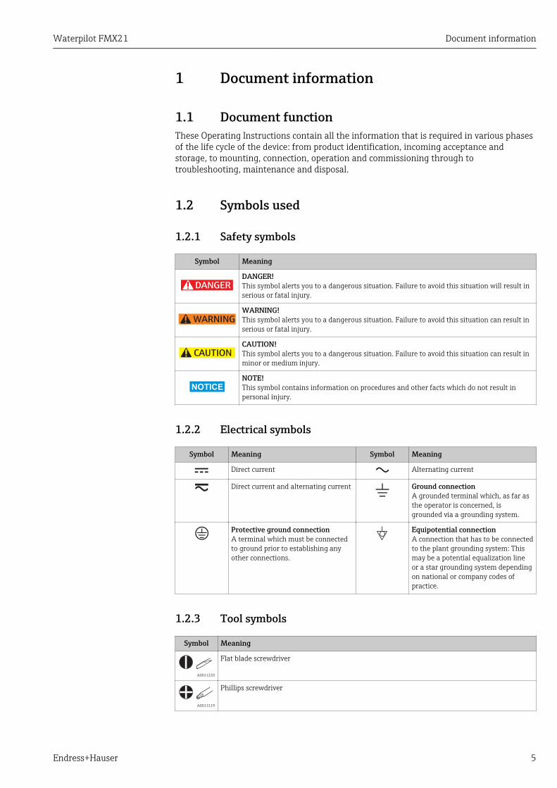
Symbol Meaning
DANGER
DANGER!This symbol alerts you to a dangerous situation. Failure to avoid this situation will result inserious or fatal injury.
WARNING
WARNING!This symbol alerts you to a dangerous situation. Failure to avoid this situation can result inserious or fatal injury.
CAUTION
CAUTION!This symbol alerts you to a dangerous situation. Failure to avoid this situation can result inminor or medium injury.
NOTICE
NOTE!This symbol contains information on procedures and other facts which do not result inpersonal injury.
1.2.2 Electrical symbols
Symbol Meaning Symbol Meaning
Direct current Alternating current
Direct current and alternating current Ground connectionA grounded terminal which, as far asthe operator is concerned, isgrounded via a grounding system.
Protective ground connectionA terminal which must be connectedto ground prior to establishing anyother connections.
Equipotential connectionA connection that has to be connectedto the plant grounding system: Thismay be a potential equalization lineor a star grounding system dependingon national or company codes ofpractice.
1.2.3 Tool symbols
Symbol Meaning
A0011220
Flat blade screwdriver
A0011219
Phillips screwdriver

Document information Waterpilot FMX21
6 Endress+Hauser
Symbol Meaning
A0011221
Allen key
A0011222
Open-ended wrench
1.2.4 Symbols for certain types of information
Symbol Meaning
PermittedProcedures, processes or actions that are permitted.
PreferredProcedures, processes or actions that are preferred.
ForbiddenProcedures, processes or actions that are forbidden.
TipIndicates additional information.
Reference to documentation
Reference to page
Reference to graphic
, …, Series of steps
Result of a step
Help in the event of a problem
Visual inspection
1.2.5 Symbols in graphics
Symbol Meaning
1, 2, 3 ... Item numbers
, …, Series of steps
A, B, C, ... Views
A-A, B-B, C-C, ... Sections
1.3 DocumentationThe document types listed are available:In the Download Area of the Endress+Hauser Internet site: www.endress.com →Download
1.3.1 Technical Information (TI): planning aid for your deviceTI00431P:
The document contains all the technical data on the device and provides an overview ofthe accessories and other products that can be ordered for the device.
Waterpilot FMX21 Document information
Endress+Hauser 7
1.3.2 Brief Operating Instructions (KA): getting the 1st measuredvalue quickly
FMX21 4 to 20 mA HART - KA01189P:
The Brief Operating Instructions contain all the essential information from incomingacceptance to initial commissioning.
1.3.3 Safety Instructions (XA)Depending on the approval, the following Safety Instructions (XA) are supplied with thedevice. They are an integral part of the Operating Instructions.
Directive Type of protection Category Documentation Option 1)
ATEX Ex ia IIC II 2 G XA00454P BD
ATEX Ex nA IIC II 3 G XA00485P BE
IECEx Ex ia IIC n/a XA00455P IC
CSA C/US Ex ia IIC n/a ZD00232P(960008976)
CE
FM AEx ia IIC n/a ZD00231P(960008975)
FE
NEPSI Ex ia IIC n/a XA00456P NA
INMETRO Ex ia IIC n/a XA01066P MA
1) Product Configurator order code for "Approval"
The nameplate indicates the Safety Instructions (XA) that are relevant to the device.
1.4 Terms and abbreviations
URL OPLMWPLRL
0
p
LRV URV
1
2
3
4
A0029505
Document information Waterpilot FMX21
8 Endress+Hauser
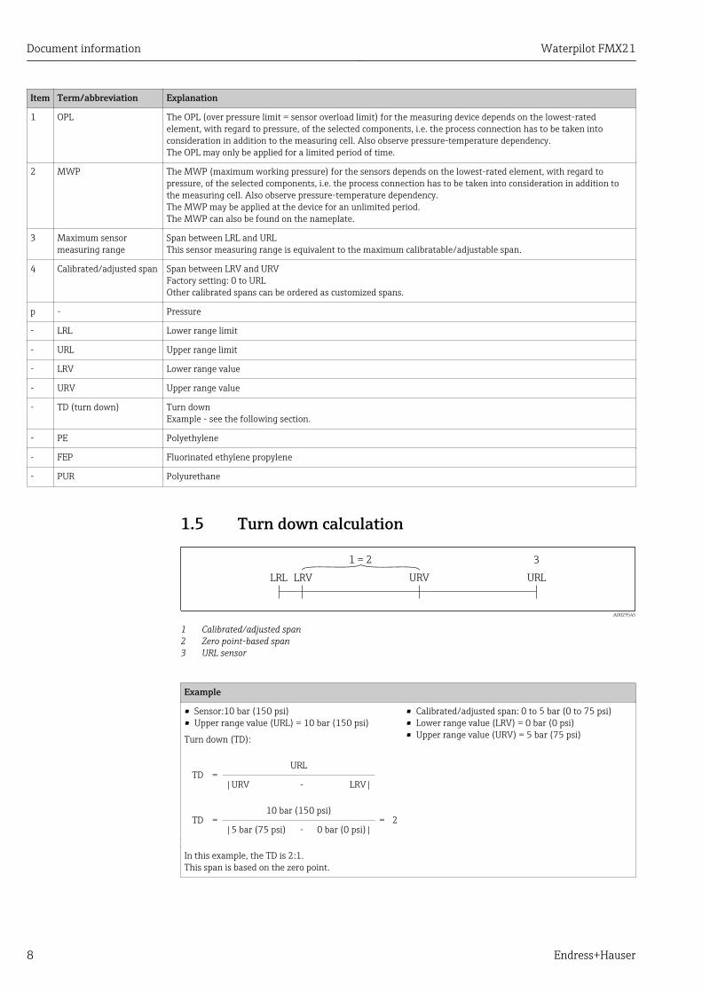
Item Term/abbreviation Explanation
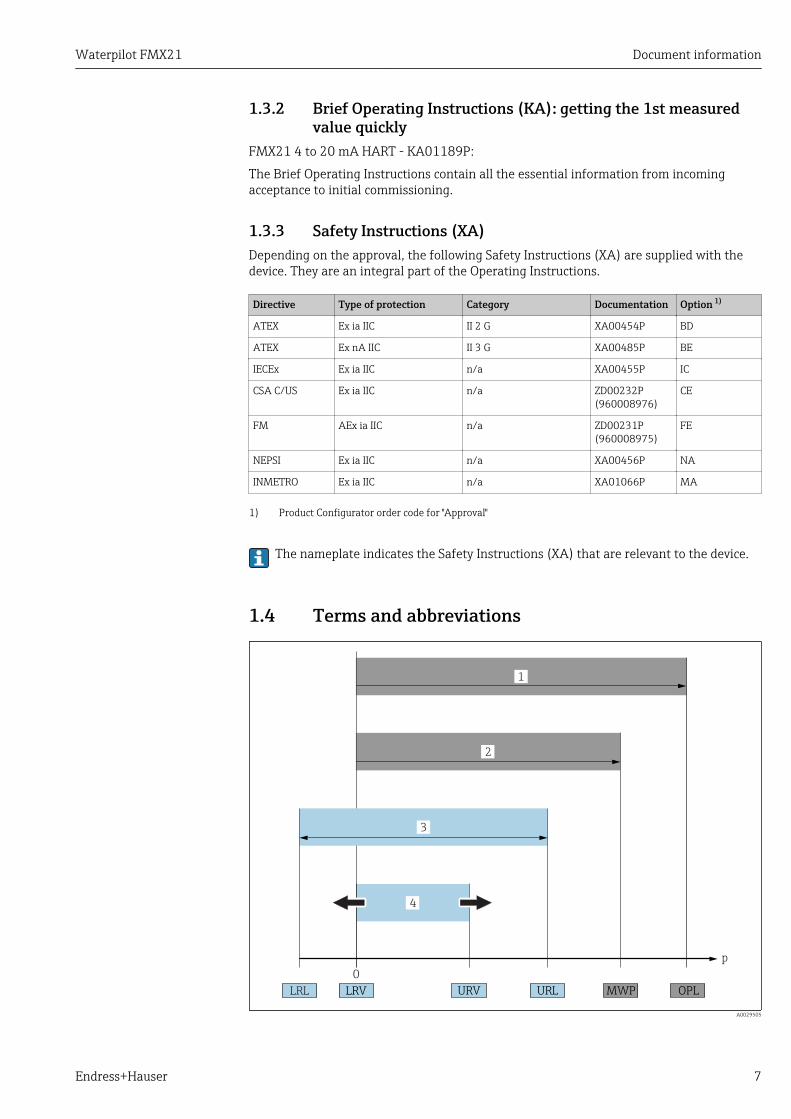
1 OPL The OPL (over pressure limit = sensor overload limit) for the measuring device depends on the lowest-ratedelement, with regard to pressure, of the selected components, i.e. the process connection has to be taken intoconsideration in addition to the measuring cell. Also observe pressure-temperature dependency.The OPL may only be applied for a limited period of time.
2 MWP The MWP (maximum working pressure) for the sensors depends on the lowest-rated element, with regard topressure, of the selected components, i.e. the process connection has to be taken into consideration in addition tothe measuring cell. Also observe pressure-temperature dependency.The MWP may be applied at the device for an unlimited period.The MWP can also be found on the nameplate.
3 Maximum sensormeasuring range
Span between LRL and URLThis sensor measuring range is equivalent to the maximum calibratable/adjustable span.
4 Calibrated/adjusted span Span between LRV and URVFactory setting: 0 to URLOther calibrated spans can be ordered as customized spans.
p - Pressure
- LRL Lower range limit
- URL Upper range limit
- LRV Lower range value
- URV Upper range value
- TD (turn down) Turn downExample - see the following section.
- PE Polyethylene
- FEP Fluorinated ethylene propylene
- PUR Polyurethane
1.5 Turn down calculation
LRV URLURVLRL
1 = 2 3
A0029545
1 Calibrated/adjusted span2 Zero point-based span3 URL sensor
Example
• Sensor:10 bar (150 psi)• Upper range value (URL) = 10 bar (150 psi)
Turn down (TD):
• Calibrated/adjusted span: 0 to 5 bar (0 to 75 psi)• Lower range value (LRV) = 0 bar (0 psi)• Upper range value (URV) = 5 bar (75 psi)
TD =URL
|URV - LRV|
TD =10 bar (150 psi)
= 2|5 bar (75 psi) - 0 bar (0 psi)|
In this example, the TD is 2:1.This span is based on the zero point.
Waterpilot FMX21 Basic safety instructions
Endress+Hauser 9
2 Basic safety instructions
2.1 Requirements concerning the staffThe personnel for installation, commissioning, diagnostics and maintenance must fulfillthe following requirements:‣ Trained, qualified specialists: must have a relevant qualification for this specific
function and task‣ Are authorized by the plant owner/operator‣ Are familiar with federal/national regulations‣ Before beginning work, the specialist staff must have read and understood the
instructions in the Operating Instructions and supplementary documentation as well asin the certificates (depending on the application)
‣ Following instructions and basic conditions
The operating personnel must fulfill the following requirements:‣ Being instructed and authorized according to the requirements of the task by the
facility's owner-operator‣ Following the instructions in these Operating Instructions
2.2 Designated use
2.2.1 Application and mediaThe Waterpilot FMX21 is a hydrostatic pressure sensor for measuring the level of freshwater, wastewater and salt water. The temperature is measured simultaneously in the caseof sensor versions with a Pt100 resistance thermometer.
An optional temperature head transmitter converts the Pt100 signal to a 4 to 20 mAsignal with superimposed digital communication protocol HART 6.0.
2.2.2 Incorrect useThe manufacturer is not liable for damage caused by improper or non-designated use.
Verification for borderline cases:‣ For special fluids and fluids for cleaning, Endress+Hauser is glad to provide assistance
in verifying the corrosion resistance of fluid-wetted materials, but does not accept anywarranty or liability.
2.3 Workplace safetyFor work on and with the device:‣ Wear the required personal protective equipment according to federal/national
regulations.‣ Switch off the supply voltage before connecting the device.
2.4 Operational safetyRisk of injury!‣ Operate the device in proper technical condition and fail-safe condition only.‣ The operator is responsible for interference-free operation of the device.

Basic safety instructions Waterpilot FMX21
10 Endress+Hauser
Modifications to the deviceUnauthorized modifications to the device are not permitted and can lead to unforeseeabledangers.‣ If, despite this, modifications are required, consult with Endress+Hauser.
RepairsTo ensure continued operational safety and reliability,‣ Carry out repairs on the device only if they are expressly permitted.‣ Observe federal/national regulations pertaining to repair of an electrical device.‣ Use original spare parts and accessories from Endress+Hauser only.
Hazardous areaTo eliminate danger to persons or the facility when the device is used in the approval-related area (e.g. explosion protection, pressure vessel safety):‣ Check the nameplate to verify if the device ordered can be put to its intended use in the
approval-related area.‣ Observe the specifications in the separate supplementary documentation that is an
integral part of these Instructions.
2.5 Product safetyThis measuring device is designed in accordance with good engineering practice to meetstate-of-the-art safety requirements, has been tested, and left the factory in a condition inwhich it is safe to operate.
It meets general safety standards and legal requirements. It also complies with the ECdirectives listed in the device-specific EC Declaration of Conformity. Endress+Hauserconfirms this by affixing the CE mark to the device.

Waterpilot FMX21 Product description
Endress+Hauser 11
3 Product description
3.1 FunctionThe ceramic measuring cell is a dry measuring cell i.e. the pressure acts directly on therobust, ceramic process isolating diaphragm of the Waterpilot FMX21. Changes in airpressure are guided via a pressure compensation tube through the extension cable to therear of the ceramic process isolating diaphragm and are compensated for. A pressure-dependent change in capacitance, caused by the movement of the process isolatingdiaphragm, is measured at the electrodes of the ceramic carrier. The electronics unit thenconverts this to a signal that is proportional to the pressure and linear to the level.
h
2
1
patm
phydr.
p = p + patm hydr.
patm
patm
h ~ p
r • gh =
pRel.: p = (p + p ) - psens atm hydr. atm
p = p + patm hydr.
Abs.: p = (p + p )sens atm hydr.
A0019140
1 Ceramic measuring cell2 Pressure compensation tubeh Height levelp Total pressure = atmospheric pressure + hydrostatic pressureρ Density of the mediumg Acceleration due to gravityPhydr. Hydrostatic pressurePatm Atmospheric pressurePsens Pressure displayed on the sensor

Incoming acceptance and product identification Waterpilot FMX21
12 Endress+Hauser
4 Incoming acceptance and productidentification
4.1 Incoming acceptance
A0015502
DELIVERY NOTE
1 = 2
A0016870
Is the order code on the delivery note (1) identical to the order code onthe product sticker (2)?
A0026535
A0015502
A0026536
Are the goods undamaged?
A0015502
Dat./Insp.:
FW
.Ver.
:D
ev.
Rev.
:
Cal./A
dj.
Mat:
L=
Ser. n
o.:
Ord
er
code:
Ext.
ord
er
code:
TA
G:
Wate
rpilo
t F
MX
21
Made in G
erm
any,
D-7
9689 M
aulb
urg
p
DELIVERY NOTE
Dat./Insp.:
FW.Ver.:Dev.Rev.:
Cal./Adj.
Mat: L=
Ser. no.:Order code:Ext. order code:
TAG:
Waterpilot FMX21
Made in Germany, D-79689 Maulburg
p
A0026537
Do the data on the nameplate correspond to the order specifications andthe delivery note?
Waterpilot FMX21 Incoming acceptance and product identification
Endress+Hauser 13
A0015502
A0022106
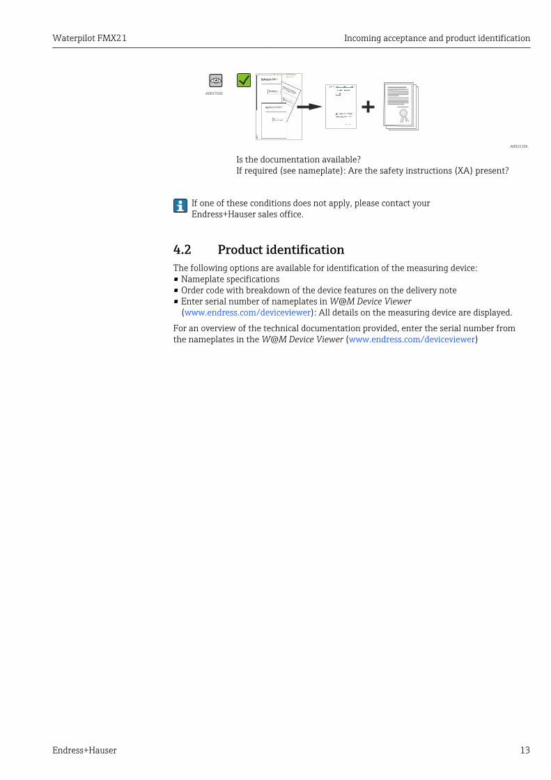
Is the documentation available?If required (see nameplate): Are the safety instructions (XA) present?
If one of these conditions does not apply, please contact yourEndress+Hauser sales office.
4.2 Product identificationThe following options are available for identification of the measuring device:• Nameplate specifications• Order code with breakdown of the device features on the delivery note• Enter serial number of nameplates in W@M Device Viewer
(www.endress.com/deviceviewer): All details on the measuring device are displayed.
For an overview of the technical documentation provided, enter the serial number fromthe nameplates in the W@M Device Viewer (www.endress.com/deviceviewer)
Incoming acceptance and product identification Waterpilot FMX21
14 Endress+Hauser
4.3 Nameplates
4.3.1 Nameplates on extension cable
Dat./Insp.:
FW.Ver.:Dev.Rev.:
Cal./Adj.
Mat: L=
Ser. no.:Order code:Ext. order code:
TAG:
Waterpilot FMX21
Made in Germany, D-79689 Maulburg
p
1 2
17
161514
3 4
5
6/7
89101112
13
A0018802
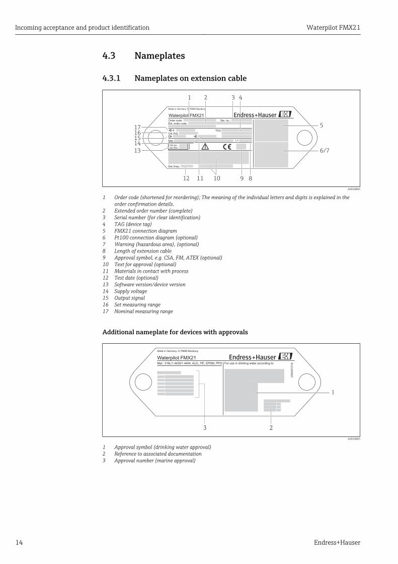
1 Order code (shortened for reordering); The meaning of the individual letters and digits is explained in theorder confirmation details.
2 Extended order number (complete)3 Serial number (for clear identification)4 TAG (device tag)5 FMX21 connection diagram6 Pt100 connection diagram (optional)7 Warning (hazardous area), (optional)8 Length of extension cable9 Approval symbol, e.g. CSA, FM, ATEX (optional)10 Text for approval (optional)11 Materials in contact with process12 Test date (optional)13 Software version/device version14 Supply voltage15 Output signal16 Set measuring range17 Nominal measuring range
Additional nameplate for devices with approvals
Mat.: 316L/1.4435/1.4404, Al O , PE, EPDM, PPO2 3 For use in drinking water according to:
Made in Germany, D-79689 Maulburg
Waterpilot FMX21
250002737-B
1
23
A0018805
1 Approval symbol (drinking water approval)2 Reference to associated documentation3 Approval number (marine approval)
Waterpilot FMX21 Incoming acceptance and product identification
Endress+Hauser 15
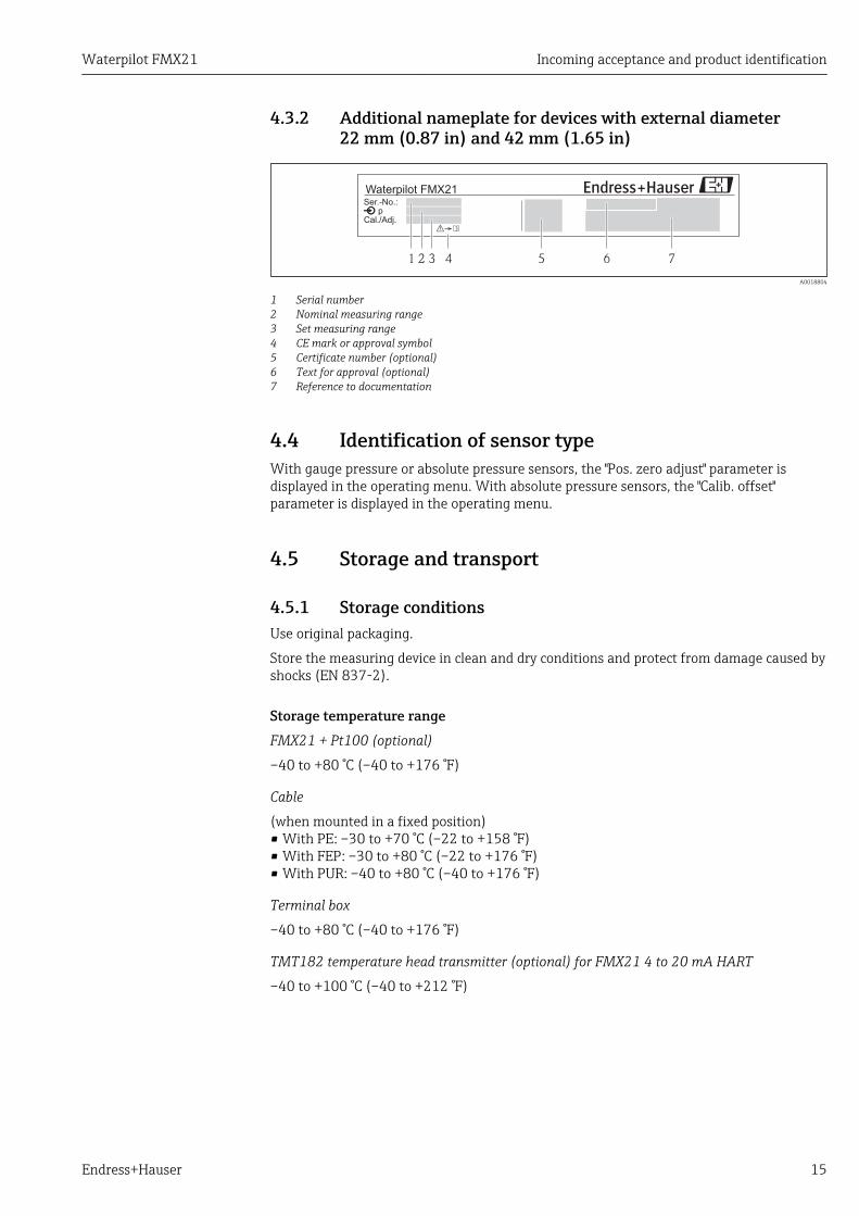
4.3.2 Additional nameplate for devices with external diameter22 mm (0.87 in) and 42 mm (1.65 in)
xInstall per dwg. 96000xxxx-
Ser.-No.:p
Waterpilot FMX21
Cal./Adj.
1 2 3 4 5 6 7
A0018804
1 Serial number2 Nominal measuring range3 Set measuring range4 CE mark or approval symbol5 Certificate number (optional)6 Text for approval (optional)7 Reference to documentation
4.4 Identification of sensor typeWith gauge pressure or absolute pressure sensors, the "Pos. zero adjust" parameter isdisplayed in the operating menu. With absolute pressure sensors, the "Calib. offset"parameter is displayed in the operating menu.
4.5 Storage and transport
4.5.1 Storage conditionsUse original packaging.
Store the measuring device in clean and dry conditions and protect from damage caused byshocks (EN 837-2).
Storage temperature rangeFMX21 + Pt100 (optional)
–40 to +80 °C (–40 to +176 °F)
Cable
(when mounted in a fixed position)• With PE: –30 to +70 °C (–22 to +158 °F)• With FEP: –30 to +80 °C (–22 to +176 °F)• With PUR: –40 to +80 °C (–40 to +176 °F)
Terminal box
–40 to +80 °C (–40 to +176 °F)
TMT182 temperature head transmitter (optional) for FMX21 4 to 20 mA HART
–40 to +100 °C (–40 to +212 °F)
Incoming acceptance and product identification Waterpilot FMX21
16 Endress+Hauser
4.5.2 Transporting the product to the measuring pointLWARNING
Incorrect transport!Device or cable may become damaged, and there is a risk of injury!‣ Transport measuring device in the original packaging.‣ Follow the safety instructions and transport conditions for devices weighing more than
18 kg (39.6 lbs).
4.6 Scope of deliveryThe scope of delivery comprises:• Waterpilot FMX21, optionally with integrated Pt100 resistance thermometer• Optional accessories
Documentation supplied:• The Operating Instructions BA00380P are available on the internet. → see:
www.de.endress.com → Downloads.• Brief Operating Instructions KA01189P• Final inspection report• Drinking water approvals (optional): SD00289P, SD00319P, SD00320P• Devices that are suitable for use in hazardous areas: Additional documentation e.g.
Safety instructions (XA, ZD)

Waterpilot FMX21 Installation
Endress+Hauser 17
5 Installation
5.1 Installation conditions
1
2
3
4
5
6
7
8
9
Dat./Insp.:
FW.Ver.: xxxxDev.Rev.: xxxx
Cal./Adj.
Mat: L=
Ser. no.: xxxxxxxxxxxxxOrder code: xxxxxxxxxxxxxxxxxxxxxxExt. order code: xxxxxxxxxxxxxxxxxxxxxx
TAG: xxxxxxxxxxxxxxxxxxxxxxxxxxxxxxxxxxxxxxxxxxxxxxxxxxx
Waterpilot FMX21
Made in Germany, D-79689 Maulburg
p
Ex ia IIC T6-T4£-10°C Ta 70°C£ Ta 40°C for T6£ Ta 70°C for T4£
Ui 30VDC ; Ii 133mA ; Pi 1W£ £ £
II 2G
Ci= 5nF + 180pF/m ; Li= 1 µH/m
Warning!Avoid electrostaticcharge
0...400mbar4... 20 mA
0...600mbar red +black -
yellow-green
4…20 mA
Senso
r
25
00
02
73
6--
10,5... 35VDC
XA xxxxxP-XX/XXXX
TÜV 01 ATEX 1685
PPS/Polyolefin AL2O3 FEP EPDM
OPEN
CLOSE
90°
90°
Warning:Avoid electrostatic charge in explosive atmosphere.See instructions
Terminal Box for FMX21
A0018770
1 Cable mounting screw (can be ordered as an accessory)2 Terminal box (can be ordered as an accessory)3 Bending radius of extension cable > 120 mm (4.72 in)4 Mounting clamp (can be ordered as an accessory)5 Extension cable6 Guide tube7 Waterpilot FMX218 Additional weight can be ordered as an accessory for the FMX21 with external diameter of 22 mm (0.87 in)
and 29 mm (1.14 in)9 Protection cap
Installation Waterpilot FMX21
18 Endress+Hauser
5.2 Additional mounting instructions• Cable length
– Customer-specific in meters or feet.– Limited cable length when performing installation with freely suspended device with
cable mounting screw or mounting clamp, as well as for FM/CSA approval: max.300 m (984 ft).
• Sideways movement of the level probe can result in measuring errors. For this reason,install the probe at a point free from flow and turbulence, or use a guide tube. Theinternal diameter of the guide tube should be at least 1 mm (0.04 in) greater than theexternal diameter of the selected FMX21.
• To avoid mechanical damage to the measuring cell, the device is equipped with aprotection cap.
• The cable must end in a dry room or a suitable terminal box. The terminal box fromEndress+Hauser provides humidity and climatic protection and is suitable for installationoutdoors → 117.
• Cable length tolerance: < 5 m (16 ft): ±17.5 mm (0.69 in); > 5 m (16 ft): ±0.2 %• If the cable is shortened, the filter at the pressure compensation tube must be
reattached. Endress+Hauser offers a cable shortening kit for this purpose → 117(documentation SD00552P/00/A6).
• Endress+Hauser recommends using twisted, shielded cable.• In shipbuilding applications, measures are required to restrict the spread of fire along
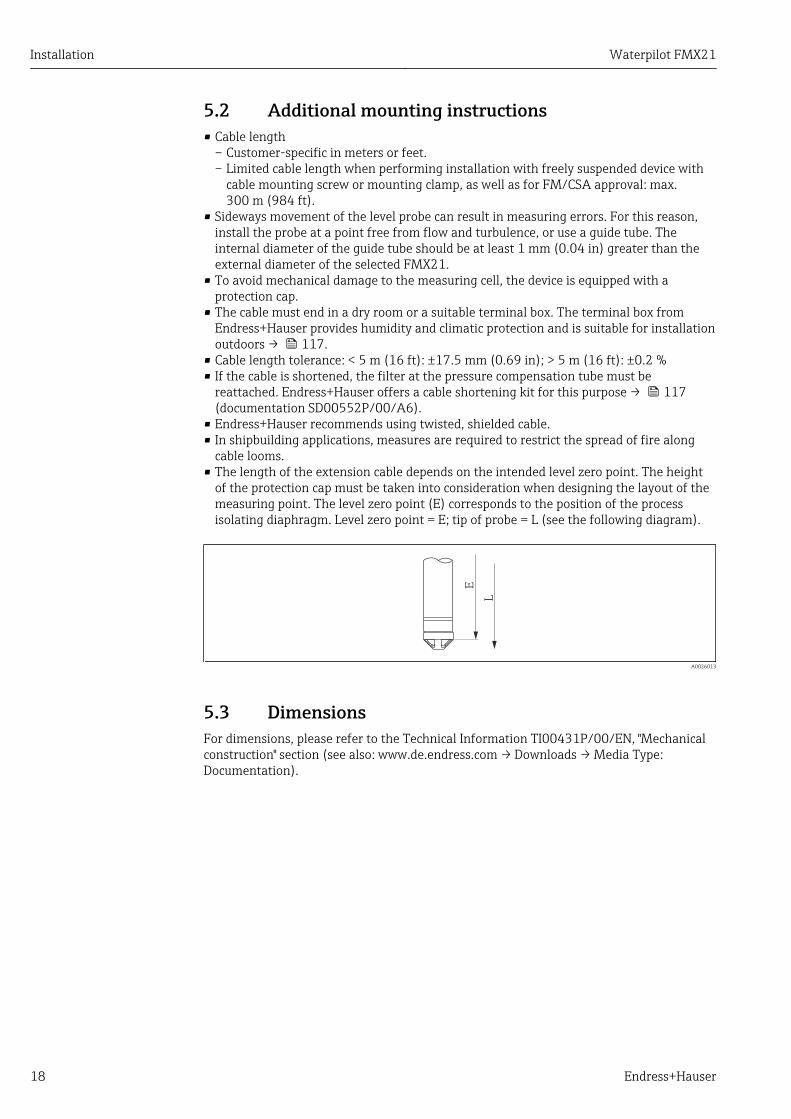
cable looms.• The length of the extension cable depends on the intended level zero point. The height
of the protection cap must be taken into consideration when designing the layout of themeasuring point. The level zero point (E) corresponds to the position of the processisolating diaphragm. Level zero point = E; tip of probe = L (see the following diagram).
L
E
A0026013
5.3 DimensionsFor dimensions, please refer to the Technical Information TI00431P/00/EN, "Mechanicalconstruction" section (see also: www.de.endress.com → Downloads → Media Type:Documentation).

Waterpilot FMX21 Installation
Endress+Hauser 19
5.4 Mounting the Waterpilot with a mounting clamp
1
2
3
A0018793
1 Extension cable2 Suspension clamp3 Clamping jaws
5.4.1 Mounting the suspension clamp:1. Mount the suspension clamp (item 2). Take the weight of the extension cable (item
1) and the device into account when selecting the fastening point.
2. Push up the clamping jaws (item 3). Place the extension cable (item 1) between theclamping jaws as shown in the graphic.
3. Hold the extension cable (item 1) in position and push the clamping jaws (item 3)back down. Tap the clamping jaws gently from above to fix them in place.
Installation Waterpilot FMX21
20 Endress+Hauser
5.5 Mounting the Waterpilot with a cable mountingscrew
+4
0
(+
1.5
7)
1
6
8
7
2
3
4
5
36
41
A0018794
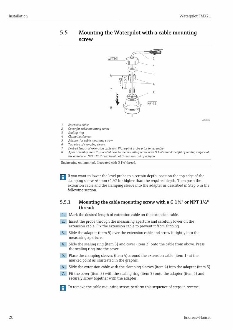
1 Extension cable2 Cover for cable mounting screw3 Sealing ring4 Clamping sleeves5 Adapter for cable mounting screw6 Top edge of clamping sleeve7 Desired length of extension cable and Waterpilot probe prior to assembly8 After assembly, item 7 is located next to the mounting screw with G 1½" thread: height of sealing surface of
the adapter or NPT 1½" thread height of thread run-out of adapter
Engineering unit mm (in). Illustrated with G 1½" thread.
If you want to lower the level probe to a certain depth, position the top edge of theclamping sleeve 40 mm (4.57 in) higher than the required depth. Then push theextension cable and the clamping sleeve into the adapter as described in Step 6 in thefollowing section.
5.5.1 Mounting the cable mounting screw with a G 1½" or NPT 1½"thread:
1. Mark the desired length of extension cable on the extension cable.
2. Insert the probe through the measuring aperture and carefully lower on theextension cable. Fix the extension cable to prevent it from slipping.
3. Slide the adapter (item 5) over the extension cable and screw it tightly into themeasuring aperture.
4. Slide the sealing ring (item 3) and cover (item 2) onto the cable from above. Pressthe sealing ring into the cover.
5. Place the clamping sleeves (item 4) around the extension cable (item 1) at themarked point as illustrated in the graphic.
6. Slide the extension cable with the clamping sleeves (item 4) into the adapter (item 5)
7. Fit the cover (item 2) with the sealing ring (item 3) onto the adapter (item 5) andsecurely screw together with the adapter.
To remove the cable mounting screw, perform this sequence of steps in reverse.
Waterpilot FMX21 Installation
Endress+Hauser 21
LCAUTIONRisk of injury!‣ Use only in unpressurized vessels.
5.6 Mounting the terminal boxThe optional terminal box is mounted using four screws (M4). For the dimensions of theterminal box, please see the Technical Information TI00431P/00/ EN, "Mechanicalconstruction" section (see also: www.de.endress.com → Downloads → Media Type:Documentation).
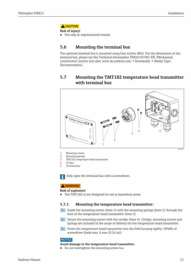
5.7 Mounting the TMT182 temperature head transmitterwith terminal box
1
3
2
6
5
4
3
CLOSE
90°
OPEN
90°
Warning:Avoid electrostatic charge in explosive atmosphere.
See instructions
Terminal Box for FMX21
1
2
34 5
A0018813
1 Mounting screws2 Mounting springs3 TMT182 temperature head transmitter4 Circlips5 Terminal box
Only open the terminal box with a screwdriver.
LWARNINGRisk of explosion!‣ The TMT182 is not designed for use in hazardous areas.
5.7.1 Mounting the temperature head transmitter:1. Guide the mounting screws (item 1) with the mounting springs (item 2) through the
bore of the temperature head transmitter (item 3)
2. Secure the mounting screws with the circlips (item 4). Circlips, mounting screws andsprings are included in the scope of delivery for the temperature head transmitter.
3. Screw the temperature head transmitter into the field housing tightly. (Width ofscrewdriver blade max. 6 mm (0.24 in))
NOTICEAvoid damage to the temperature head transmitter.‣ Do not overtighten the mounting screw too.
Installation Waterpilot FMX21
22 Endress+Hauser
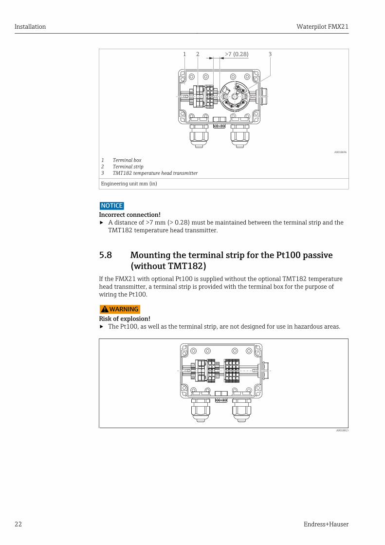
>7 (0.28)1 2 3
A0018696
1 Terminal box2 Terminal strip3 TMT182 temperature head transmitter
Engineering unit mm (in)
NOTICEIncorrect connection!‣ A distance of >7 mm (> 0.28) must be maintained between the terminal strip and the
TMT182 temperature head transmitter.
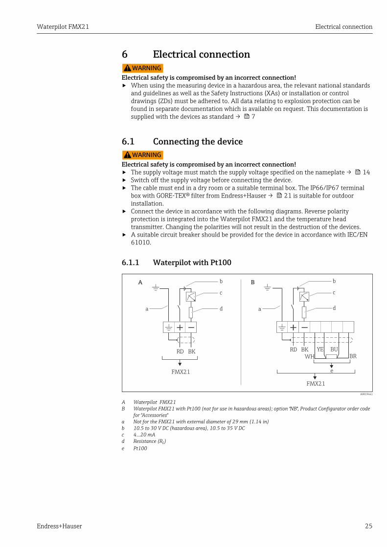
5.8 Mounting the terminal strip for the Pt100 passive(without TMT182)
If the FMX21 with optional Pt100 is supplied without the optional TMT182 temperaturehead transmitter, a terminal strip is provided with the terminal box for the purpose ofwiring the Pt100.
LWARNINGRisk of explosion!‣ The Pt100, as well as the terminal strip, are not designed for use in hazardous areas.
A0018815

Waterpilot FMX21 Installation
Endress+Hauser 23
5.9 Cable marking
A0030955
• To make installation easier, Endress+Hauser marks the extension cable if a customer-specific length has been ordered.Ordering information: Product Configurator order code for "Service", option "IR" or "IS".
• Cable marking tolerance (distance to lower end of level probe):Cable length < 5 m (16 ft): ±17.5 mm (0.69 in)Cable length > 5 m (16 ft): ±0.2 %
• Material: PET, stick-on label: acrylic• Immunity to temperature change: –30 to +100 °C (–22 to +212 °F)
NOTICEThe marking is used exclusively for installation purposes.‣ The mark must be thoroughly removed without trace in the case of devices with
drinking water approval. The extension cable must not be damaged in the process.
Not for use of the FMX21 in hazardous areas.
5.10 Cable shortening kit
A0030948
The cable shortening kit is used to shorten a cable easily and professionally.
The cable shortening kit is not designed for the FMX21 with FM/CSA approval.
• Ordering information: Product Configurator order code for "Accessories enclosed", option"PW"
• Associated documentation SD00552P/00/A6.

Installation Waterpilot FMX21
24 Endress+Hauser
5.11 Post-installation check
Is the device undamaged (visual inspection)?
Does the device conform to the measuring point specifications?
For example:• Process temperature• Process pressure• Ambient temperature• Measuring range
Are the measuring point identification and labeling correct (visual inspection)?
Check that all screws are firmly seated.
Waterpilot FMX21 Electrical connection
Endress+Hauser 25
6 Electrical connectionLWARNING
Electrical safety is compromised by an incorrect connection!‣ When using the measuring device in a hazardous area, the relevant national standards
and guidelines as well as the Safety Instructions (XAs) or installation or controldrawings (ZDs) must be adhered to. All data relating to explosion protection can befound in separate documentation which is available on request. This documentation issupplied with the devices as standard → 7
6.1 Connecting the deviceLWARNING
Electrical safety is compromised by an incorrect connection!‣ The supply voltage must match the supply voltage specified on the nameplate → 14‣ Switch off the supply voltage before connecting the device.‣ The cable must end in a dry room or a suitable terminal box. The IP66/IP67 terminal
box with GORE-TEX® filter from Endress+Hauser → 21 is suitable for outdoorinstallation.
‣ Connect the device in accordance with the following diagrams. Reverse polarityprotection is integrated into the Waterpilot FMX21 and the temperature headtransmitter. Changing the polarities will not result in the destruction of the devices.
‣ A suitable circuit breaker should be provided for the device in accordance with IEC/EN61010.
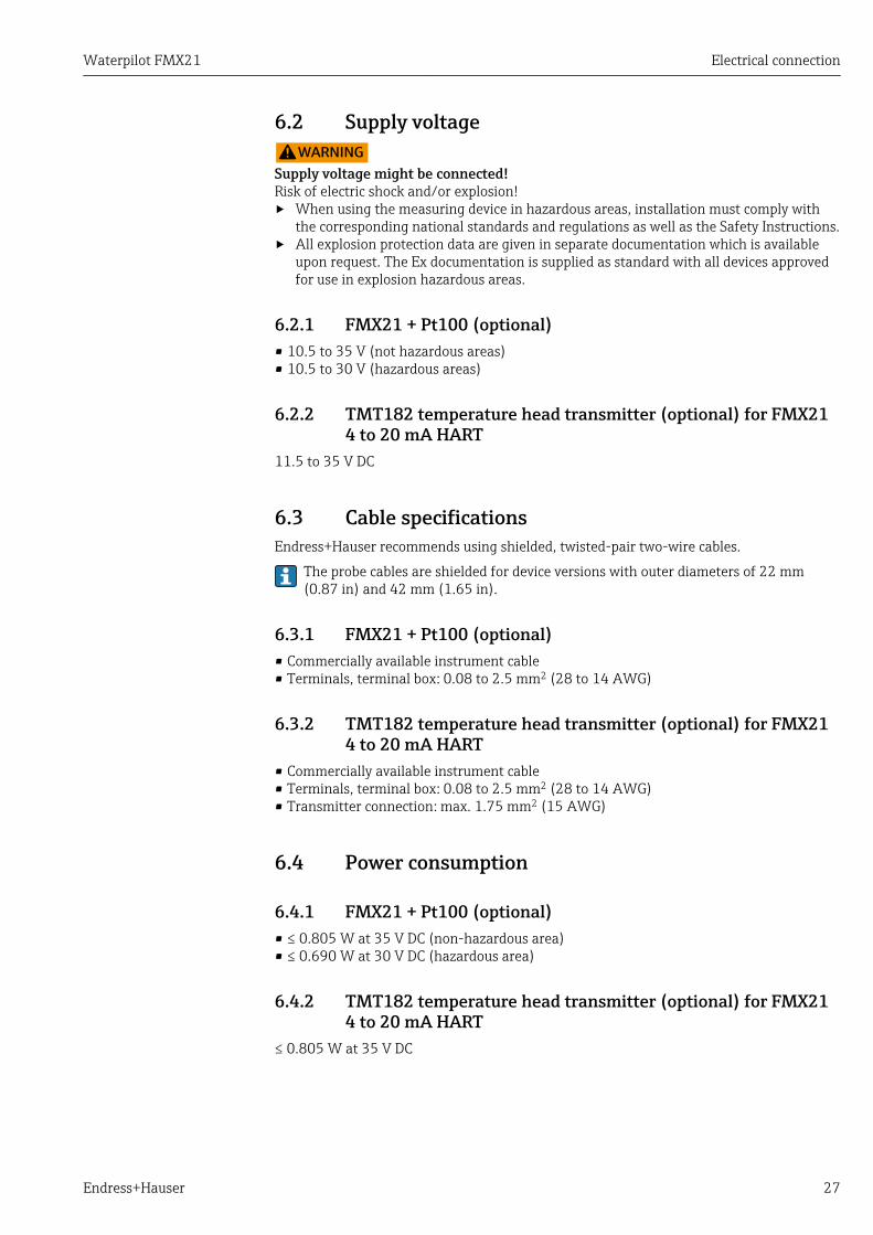
6.1.1 Waterpilot with Pt100
RD BK RD BK
WH
YE BU
BR
a
A B
e
) )
) )
c c
d d
b b
a
FMX21
FMX21
A0019441
A Waterpilot FMX21B Waterpilot FMX21 with Pt100 (not for use in hazardous areas); option "NB", Product Configurator order code
for "Accessories"a Not for the FMX21 with external diameter of 29 mm (1.14 in)b 10.5 to 30 V DC (hazardous area), 10.5 to 35 V DCc 4...20 mAd Resistance (RL)e Pt100

Electrical connection Waterpilot FMX21
26 Endress+Hauser
6.1.2 Waterpilot with Pt100 and TMT182 temperature headtransmitter for FMX21 4 to 20 mA HART
)
a
b
c
e
f
d
cd
g
RD BK
WH
YE BU
BR
2
1
6
5
4
3
)
FMX21 4...20 mA HART
A0018780
a Not for the FMX21 with external diameter of 29 mm (1.14 in)b 10.5 to 35 V DCc 4...20 mAd Resistance (RL)e TMT182 temperature head transmitter (4 to 20 mA) (not for use in hazardous areas)f 11.5 to 35 V DCg Pt1001...6 Pin assignment
Ordering information:
Pt100: Product Configurator order code for "Accessories mounted", option "NB"
TMT182: Product Configurator order code for "Accessories enclosed", option "PT"
6.1.3 Wire colorsRD = red, BK = black, WH = white, YE = yellow, BU = blue, BR = brown
6.1.4 Connection dataConnection classification as per IEC 61010-1:• Overvoltage category 1• Pollution level 1
Connection data in the hazardous areaSee relevant XA.
Waterpilot FMX21 Electrical connection
Endress+Hauser 27
6.2 Supply voltageLWARNING
Supply voltage might be connected!Risk of electric shock and/or explosion!‣ When using the measuring device in hazardous areas, installation must comply with
the corresponding national standards and regulations as well as the Safety Instructions.‣ All explosion protection data are given in separate documentation which is available
upon request. The Ex documentation is supplied as standard with all devices approvedfor use in explosion hazardous areas.
6.2.1 FMX21 + Pt100 (optional)• 10.5 to 35 V (not hazardous areas)• 10.5 to 30 V (hazardous areas)
6.2.2 TMT182 temperature head transmitter (optional) for FMX214 to 20 mA HART
11.5 to 35 V DC
6.3 Cable specificationsEndress+Hauser recommends using shielded, twisted-pair two-wire cables.
The probe cables are shielded for device versions with outer diameters of 22 mm(0.87 in) and 42 mm (1.65 in).
6.3.1 FMX21 + Pt100 (optional)• Commercially available instrument cable• Terminals, terminal box: 0.08 to 2.5 mm2 (28 to 14 AWG)
6.3.2 TMT182 temperature head transmitter (optional) for FMX214 to 20 mA HART
• Commercially available instrument cable• Terminals, terminal box: 0.08 to 2.5 mm2 (28 to 14 AWG)• Transmitter connection: max. 1.75 mm2 (15 AWG)
6.4 Power consumption
6.4.1 FMX21 + Pt100 (optional)• ≤ 0.805 W at 35 V DC (non-hazardous area)• ≤ 0.690 W at 30 V DC (hazardous area)
6.4.2 TMT182 temperature head transmitter (optional) for FMX214 to 20 mA HART
≤ 0.805 W at 35 V DC

Electrical connection Waterpilot FMX21
28 Endress+Hauser
6.5 Current consumption
6.5.1 FMX21 + Pt100 (optional)Max. current consumption: ≤ 23 mAMin. current consumption: ≥ 3.6 mA
6.5.2 TMT182 temperature head transmitter (optional) for FMX214 to 20 mA HART
• Max. current consumption: ≤ 23 mA• Min. current consumption: ≥ 3.5 mA
6.6 Connecting the measuring unit
6.6.1 Overvoltage protectionTo protect the Waterpilot and the TMT182 temperature head transmitter from largeinterference voltage peaks, Endress+Hauser recommends installing overvoltage protectionupstream and downstream of the display and/or evaluation unit as shown in the graphic.
Waterpilot FMX21 Electrical connection
Endress+Hauser 29
1
3
4
3
4
5
5
5
5
5
5
5
6
6
6
2
A
B
B
C
2
A0018941
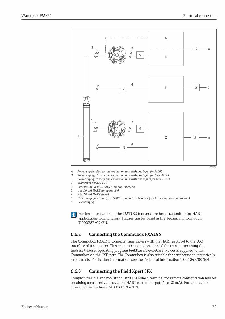
A Power supply, display and evaluation unit with one input for Pt100B Power supply, display and evaluation unit with one input for 4 to 20 mAC Power supply, display and evaluation unit with two inputs for 4 to 20 mA1 Waterpilot FMX21 HART2 Connection for integrated Pt100 in the FMX213 4 to 20 mA HART (temperature)4 4 to 20 mA HART (level)5 Overvoltage protection, e.g. HAW from Endress+Hauser (not for use in hazardous areas.)6 Power supply
Further information on the TMT182 temperature head transmitter for HARTapplications from Endress+Hauser can be found in the Technical InformationTI00078R/09/EN.
6.6.2 Connecting the Commubox FXA195The Commubox FXA195 connects transmitters with the HART protocol to the USBinterface of a computer. This enables remote operation of the transmitter using theEndress+Hauser operating program FieldCare/DeviceCare. Power is supplied to theCommubox via the USB port. The Commubox is also suitable for connecting to intrinsicallysafe circuits. For further information, see the Technical Information TI00404F/00/EN.
6.6.3 Connecting the Field Xpert SFXCompact, flexible and robust industrial handheld terminal for remote configuration and forobtaining measured values via the HART current output (4 to 20 mA). For details, seeOperating Instructions BA00060S/04/EN.

Electrical connection Waterpilot FMX21
30 Endress+Hauser
3
7 6
4
1
5
2
A0018811
1 Waterpilot FMX212 Required communication resistor ≥ 250 Ω3 Computer with operating tool (e.g. FieldCare)4 Commubox FXA195 (USB)5 Transmitter power supply unit, e.g. RN221N (with communication resistor)6 Field Xpert SFX7 VIATOR Bluetooth modem with connecting cable
Only use certified operating devices in hazardous area!
LWARNINGRisk of explosion!‣ Do not change the battery of the handheld terminal in the hazardous area.‣ When using the measuring device in hazardous areas, installation must comply with
the corresponding national standards and regulations and the Safety Instructions (XAs)or the Installation or Control Drawings (ZDs).
6.6.4 Connecting for air pressure compensation with externalmeasured value
FX
N520
1 2
3
4
A0018757
1 FieldgateFXA5202 Multidrop Connector FXN5203 Cerabar4 Waterpilot FMX21
Waterpilot FMX21 Electrical connection
Endress+Hauser 31
For applications in which condensation may occur, the use of an absolute pressure probe isrecommended. For level measurement using an absolute pressure probe, the measuredvalue is affected by fluctuations in the ambient air pressure. To correct the resultingmeasured error, you can connect an external absolute pressure sensor (e.g. Cerabar) to theHART signal line, switch the Waterpilot to burst mode and operate the Cerabar in the"Electr. Delta P" mode.
When you switch on the "Electr. Delta P" application, the external absolute pressure sensorcalculates the difference between the two pressure signals and can thus determine thelevel precisely. Only one level measured value can be corrected in this way.
For additional information, see → 53.
If using intrinsically safe devices, the regulations which apply to interconnectingintrinsically safe circuits as outlined in IEC 60079-14 (proof of intrinsic safety) mustbe observed.
6.6.5 Connecting an external temperature sensor/temperature headtransmitter for density compensation
The Waterpilot FMX21 can correct measured errors that result from fluctuations in thedensity of the water caused by temperature. Users can choose from the following options:
Use the internally measured sensor temperature of the FMX21The internally measured sensor temperature is calculated in the Waterpilot FMX21 fordensity compensation. The level signal is thus corrected according to the densitycharacteristic line of water.
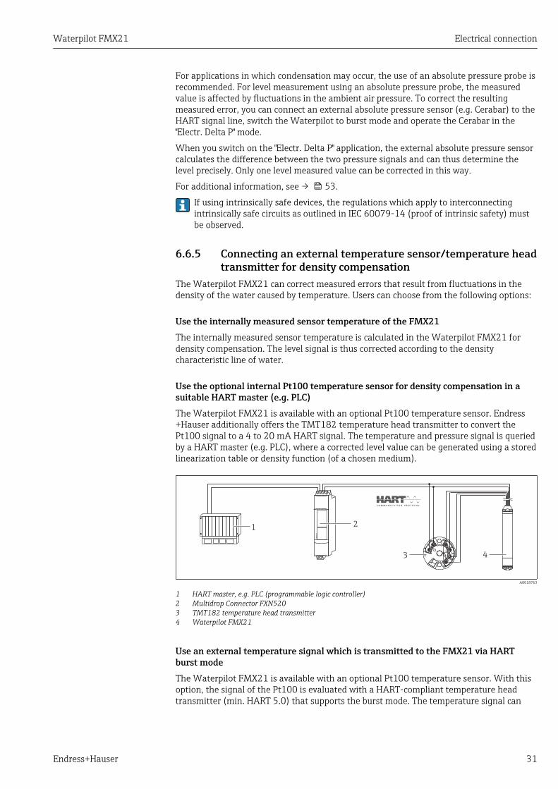
Use the optional internal Pt100 temperature sensor for density compensation in asuitable HART master (e.g. PLC)The Waterpilot FMX21 is available with an optional Pt100 temperature sensor. Endress+Hauser additionally offers the TMT182 temperature head transmitter to convert thePt100 signal to a 4 to 20 mA HART signal. The temperature and pressure signal is queriedby a HART master (e.g. PLC), where a corrected level value can be generated using a storedlinearization table or density function (of a chosen medium).
12
3 4
FX
N520
A0018763
1 HART master, e.g. PLC (programmable logic controller)2 Multidrop Connector FXN5203 TMT182 temperature head transmitter4 Waterpilot FMX21
Use an external temperature signal which is transmitted to the FMX21 via HARTburst modeThe Waterpilot FMX21 is available with an optional Pt100 temperature sensor. With thisoption, the signal of the Pt100 is evaluated with a HART-compliant temperature headtransmitter (min. HART 5.0) that supports the burst mode. The temperature signal can

Electrical connection Waterpilot FMX21
32 Endress+Hauser
thus be transmitted to the FMX21. The FMX21 uses this signal for density correction ofthe level signal.
The TMT182 temperature head transmitter is not suitable for this configuration.
FX
N520
4
12
3
A0018764
1 FieldgateFXA5202 Multidrop Connector FXN5203 HART-compatible temperature transmitter (e.g. TMT82)4 Waterpilot FMX21
Without additional compensation due to the anomaly of water, errors of up to 4% mayoccur at a temperature of +70 °C (+158 °F), for example. With density compensation, thiserror can be decreased to 0.5 % in the entire temperature range from0 to +70 °C (+32 to +158 °F).
For additional information, see → 55.
For further information on the devices, please refer to the relevant TechnicalInformation:• TI01010T: TMT82 temperature transmitter (4 to 20 mA HART)• TI00369F: Fieldgate FXA520• TI00400F: Multidrop-Connector FXN520
6.7 Post-connection check
Is the device or cable undamaged (visual check)?
Do the cables comply with the requirements ?
Do the cables have adequate strain relief?
Are all cable glands installed, securely tightened and leak-tight?
Does the supply voltage match the specifications on the nameplate?
Is the terminal assignment correct ?
Waterpilot FMX21 Operation options
Endress+Hauser 33
7 Operation optionsEndress+Hauser offers comprehensive measuring point solutions with display and/orevaluation units for the Waterpilot FMX21 HART and TMT182 temperature headtransmitter.
Your Endress+Hauser service organization would be glad to be of service if you haveany other questions. Contact addresses can be found on the website atwww.endress.com/worldwide
7.1 Overview of operating options
7.1.1 Operation using Endress+Hauser operating program
FieldCareThe FieldCare operating program is an Endress+Hauser asset management tool based onFDT technology. With FieldCare, you can configure all Endress+Hauser devices as well asdevices from other manufacturers that support the FDT standard.
Hardware and software requirements can be found on the Internet:
www.de.endress.com → Search: FieldCare → FieldCare → Technical data.
FieldCare supports the following functions:• Configuration of transmitters in online/offline mode• Loading and saving device data (upload/download)• Documentation of the measuring point
Connection options:• HART via Commubox FXA195 and USB interface of a computer• HART via Fieldgate FXA520
• Further information on FieldCare and software download can be found on theinternet (www.de.endress.com ® Downloads ® Text Search: FieldCare).
• Connecting the Commubox FXA195• As not all internal device dependencies can be mapped in offline operation, the
consistency of the parameters must be checked once again before they aretransmitted to the device.
DeviceCare
Function scope
Tool for connecting and configuring Endress+Hauser field devices.
The fastest way to configure Endress+Hauser field devices is with the dedicated"DeviceCare" tool. Together with the device type managers (DTMs) it presents a convenient,comprehensive solution.
For details, see Innovation brochure IN01047S
7.1.2 Operation via Field Xpert SFXCompact, flexible and robust industrial handheld terminal for remote configuration and forobtaining measured values via the HART current output or FOUNDATION Fieldbus. Fordetails, see the Operating Instructions BA00060S/04.

Operation options Waterpilot FMX21
34 Endress+Hauser
7.2 Operating conceptOperation with an operating menu is based on an operation concept with "user roles" .
User role Meaning
Operator Operators are responsible for the devices during normal "operation". This is usually limited to thereading of process values. If the work with the devices goes beyond reading, it concerns simple,application-specific functions that are used in operation. Should an error occur, these userssimple forward the information on the errors but do not intervene themselves.
Maintenance Service engineers usually work with the devices in the phases following device commissioning.They are primarily involved in maintenance and troubleshooting activities for which simplesettings have to be made at the device. Technicians work with the devices over the entire lifecycle of the product. Thus, commissioning and advanced settings and configurations are some ofthe tasks they have to carry out.
Expert Experts work with the devices over the entire life cycle of the device, but, in part, have highrequirements on the devices. Individual parameters/functions from the overall functionality ofthe devices are required for this purpose time and again. In addition to technical, process-oriented tasks, experts can also perform administrative tasks (e.g. user administration). "Experts"can avail of the entire parameter set.
7.3 Structure of the operating menu
User role Submenu Meaning/use
Operator Display/operat.
Contains parameters that are needed to configure the measured value display(selecting the values displayed, display format, etc.). With this submenu, users canchange the measured value display without affecting the actual measurement.
Maintenance setup Contains all the parameters that are needed to commission measuring operations.This submenu has the following structure:• Standard setup parameters
A wide range of parameters, which can be used to configure a typical application,is available at the start. The measuring mode selected determines whichparameters are available. After making settings for all these parameters, themeasuring operation should be completely configured in the majority of cases.
• "Extended setup" submenuThe "Extended setup" submenu contains additional parameters for more in-depthconfiguration of the measurement operation, for conversion of the measuredvalue and for scaling the output signal. This menu is split into additionalsubmenus depending on the measuring mode selected.

Waterpilot FMX21 Operation options
Endress+Hauser 35
User role Submenu Meaning/use
Maintenance Diagnosis Contains all the parameters that are needed to detect and analyze operating errors.This submenu has the following structure:• Diagnostic list
contains up to 10 currently pending error messages.• Event logbook
contains the last 10 error messages (no longer pending).• Instrument info
contains information for identifying the device.• Measured values
contains all current measured values.• Simulation
Is used to simulate pressure, level, current and alarm/warning.• Enter reset code
Expert Expert Contains all the parameters of the device (including those already in one of thesubmenus). The "Expert" submenu is structured by the function blocks of the device.It thus contains the following submenus:• System
contains all device parameters that do not affect either measurement orintegration into a distributed control system.
• Measurementcontains all parameters for configuring the measurement.
• Outputcontains all parameters for configuring the current output.
• Communicationcontains all parameters for configuring the HART interface.
• Diagnosiscontains all parameters required to detect and analyze operating errors.
7.4 Locking/unlocking operationOnce you have entered all the parameters, you can lock your entries against unauthorizedand undesired access.
The "Operator code" parameter is used to lock/unlock the device.
Operator code
Navigation Setup → Extended setup → Operator code
Read permission Operators/Service engineers/Expert
Write permission Operators/Service engineers/Expert
Description Use this function to enter a code to lock or unlock operation.
User entry • To lock: Enter a number ¹ the release code (value range: 1 to 65535).• To unlock: Enter the release code.
Factory setting 0
Note The release code is "0" in the order configuration. Another release code can be defined inthe "Code definition" parameter. If the user has forgotten the release code, the release codecan be visible by entering the number "5864".
The release code is defined in the "Code definition" parameter.
Code definition

Operation options Waterpilot FMX21
36 Endress+Hauser
Navigation Setup → Extended setup → Code definition
Read permission Operators/Service engineers/Expert
Write permission Operators/Service engineers/Expert
Description Use this function to enter a release code with which the device can be unlocked.
User entry A number from 0 to 9999
Factory setting 0
7.5 Resetting to factory settings (reset)By entering a certain code, you can completely or partially reset the entries for theparameters to the factory settings 1). Enter the code via the "Enter reset code"parameter (menu path: "Diagnosis" → "Enter reset code").
There are various reset codes for the device. The following table illustrates whichparameters are reset by the particular reset codes. To perform a reset, operation mustbe unlocked (see "Locking/unlocking operation" section → 35).
Any customer-specific configuration carried out at the factory is not affected by areset (customer-specific configuration remains). If you want to change the customer-specific configuration carried out at the factory, please contact Endress+HauserService. As there is no separate service level, the order code and serial number can bechanged without a specific release code.
Reset code 1) Description and effect
62 PowerUp reset (warm start)• The device is restarted.• Data is read back anew from the EEPROM (process is reinitialized).• Any simulation which may be running is ended.
333 User reset• This code resets all the parameters apart from:
- Device tag- Linearization table- Operating hours- Event logbook- Curr. trim 4 mA- Curr. trim 20 mA
• Any simulation which may be running is ended.• The device is restarted.
7864 Total reset• This code resets all the parameters apart from:
- Operating hours- Event logbook
• Any simulation which may be running is ended.• The device is restarted.
1) To be entered in "System" → "Management" → "Enter reset code"
After a "Total reset" in FieldCare you have to press the "refresh" button in order toensure that the measuring units are also reset.
1) . The factory setting for the individual parameters is specified in the parameter description
Waterpilot FMX21 Integrating device via HART® protocol
Endress+Hauser 37
8 Integrating device via HART® protocolVersion data for the device
Firmware version 01.00.zz • On the title page of the Operating instructions• On nameplate → 14• Firmware Version parameter
Diagnosis→ Instrument info → Firmware version
Manufacturer ID 17 (0x11) Manufacturer ID. parameterDiagnosis → Instrument info→ Manufacturer ID
Device type code 36 (0x24) Device type code parameterDiagnosis → Instrument info → Device type code
HART protocol revision 6.0 ---
Device revision 1 • On nameplate → 14• Device revision parameter
Diagnosis→ Instrument info → Device revision
The suitable device description file (DD) for the individual operating tools is listed in thetable below, along with information on where the file can be acquired.
Operating tools
Operating tool Reference sources for device descriptions (DD and DTM)
FieldCare • www.endress.com → Downloads area• CD–ROM (contact Endress+Hauser)• DVD (contact Endress+Hauser)
AMS Device Manager(Emerson Process Management)
www.endress.com → Downloads area
SIMATIC PDM(Siemens)
www.endress.com → Downloads area
Field Communicator 375, 475(Emerson Process Management)
Use update function of handheld terminal
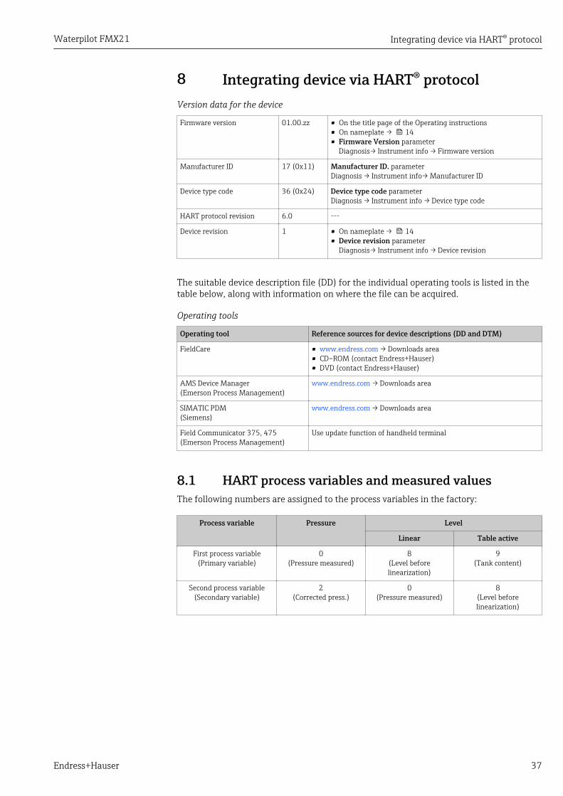
8.1 HART process variables and measured valuesThe following numbers are assigned to the process variables in the factory:
Process variable Pressure Level
Linear Table active
First process variable(Primary variable)
0(Pressure measured)
8(Level beforelinearization)
9(Tank content)
Second process variable(Secondary variable)
2(Corrected press.)
0(Pressure measured)
8(Level beforelinearization)

Integrating device via HART® protocol Waterpilot FMX21
38 Endress+Hauser
Process variable Pressure Level
Linear Table active
Third process variable(Tertiary variable)
3(Sensor pressure)
2(Corrected press.)
0(Pressure measured)
Fourth process variable(Quaternary variable)
4(Sensor temp.)
The assignment of the device variables to the process variable is displayed in theExpert → Communication → HART output menu.
The assignment of the device variables to the process variable (SV, TV, QV) can bechanged using HART command 51.
An overview of the possible device variables can be found in the following section.
8.2 Device variables and measured valuesThe following measured values are assigned to the individual device variables:
Device variable code Device variable Measured value Operating mode
0 PRESSURE_1_FINAL_VALUE Pressure measured All
1 PRESSURE_1_AFTER_DAMPING Pressure af.damp All
2 PRESSURE_1_AFTER_CALIBRATION Corrected press. All
3 PRESSURE_1_AFTER_SENSOR Corrected press. All
4 MEASURED_TEMPERATURE_1 Sensor temp. All
8 MEASURED_LEVEL_AFTER_ SIMULATION Level before lin. Only level
9 MEASURED_TANK_CONTENT_AFTER_ SIMULATION Tank content Only level
10 CORRECTED_MEASUREMENT_ DENSITY Process density Only level
12 HART_INPUT_VALUE 1) HART input val. -
251 None (no device variable is mapped) - All (but only for quaternary variable)
1) Cannot be selected as an output
The device variables can be queried from a HART® master using HART® command 9 or33.

Waterpilot FMX21 Commissioning
Endress+Hauser 39
9 CommissioningNOTICE
If a pressure smaller than the minimum permitted pressure or greater than themaximum permitted pressure is present at the device, the following messages areoutput in succession:‣ "S140 Working range P" or "F140 Working range P" (depending on the setting in the
"Alarm behav. P" parameter)‣ "S841 Sensor range" or "F841 Sensor range" (depending on the setting in the "Alarm
behav. P" parameter)‣ "S971 Adjustment" (depending on setting in "Alarm behav. P" parameter
9.1 Post-installation check and function checkBefore commissioning your measuring point, ensure that the post-installation and post-connection check have been performed.
• "Post-installation check" checklist → 24• "Post-connection check" checklist → 32
9.2 Unlocking/locking configurationIf the device is locked to prevent configuration, it must first be unlocked.
9.2.1 Locking/unlocking softwareIf the device is locked via the software (device access code), the key symbol appears in themeasured value display. If an attempt is made to write to a parameter, a prompt for thedevice access code appears. To unlock, enter the user-defined device access code.
9.3 CommissioningCommissioning comprises the following steps:• Function check → 39• Selection of the measuring mode and pressure unit → 39• Position adjustment → 40• Configuring measurement:
– Pressure measurement → 42– Level measurement → 44
9.4 Measuring mode selectionThe device is configured for the "Pressure" measuring mode as standard. Themeasuring range and the unit in which the measured value is transmitted correspondto the data on the nameplate.
LWARNINGChanging the measuring mode affects the span (URV)This situation can result in product overflow.‣ If the measuring mode is changed, the setting for the span (URV) must be checked in
the "Setup" operating menu and readjusted if necessary.
Measuring mode

Commissioning Waterpilot FMX21
40 Endress+Hauser
Navigation Setup → Measuring mode
Write permission Operators/Service engineers/Expert
Description Select the measuring mode.The operating menu is structured differently depending on the measuring mode selected.
Options • Pressure• Level
Factory setting Level
9.5 For selecting the pressure engineering unit
Press. eng. unit
Navigation Setup → Press. eng. unit
Write permission Operators/Service engineers/Expert
Description Select the pressure engineering unit. If a new pressure engineering unit is selected, allpressure-specific parameters are converted and displayed with the new unit.
Options • mbar, bar• mmH2O, mH2O, inH2O• ftH2O• Pa, kPa, MPa• psi• mmHg, inHg• kgf/cm2
Factory setting mbar or bar depending on the nominal measuring range of the sensor module, or as perorder specifications.
9.6 Position adjustmentThe pressure resulting from the orientation of the device can be corrected here.
Pos. zero adjust (relative pressure sensor)
Navigation Setup → Pos. zero adjust
Write permission Operators/Service engineers/Expert
Description Position adjustment – the pressure difference between zero (set point) and the measuredpressure need not be known.

Waterpilot FMX21 Commissioning
Endress+Hauser 41
Options • Confirm• Cancel
Example • Measured value = 2.2 mbar (0.033 psi)• You correct the measured value via the "Pos. zero adjust" parameter with the "Confirm"
option. This means that you are assigning the value 0.0 to the pressure present.• Measured value (after pos. zero adjust) = 0.0 mbar• The current value is also corrected.
Factory setting Cancel
Calib. offset
Write permission Service engineers/Expert
Description Position adjustment – the pressure difference between the set point and the measuredpressure must be known.
Example • Measured value = 982.2 mbar (14.73 psi)• You correct the measured value with the value entered (e.g. 2.2 mbar (0.033 psi)) via
the "Calib. Offset" parameter. This means that you are assigning the value 980.0 (14.7psi) to the pressure present.
• Measured value (after pos. zero adjust) = 980.0 mbar (14.7 psi)• The current value is also corrected.
Factory setting 0.0
9.7 Configuring the dampingThe output signal follows measured value changes with the delay time. This can beconfigured via the operating menu.
Damping
Navigation Setup → Damping
Write permission Operators/Service engineers/Expert(if the "Damping" DIP switch is set to "on")
Description Enter damping time (time constant t) ("Damping" DIP switch set to "on")Display damping time (time constant t) ("Damping" DIP switch set to "off").The damping affects the speed at which the measured value reacts to changes in pressure.
Input range 0.0 to 999.0 s
Factory setting 2.0 sec. or according to order specifications
Commissioning Waterpilot FMX21
42 Endress+Hauser
9.8 Configuring pressure measurement
9.8.1 Calibration with reference pressure (wet calibration)
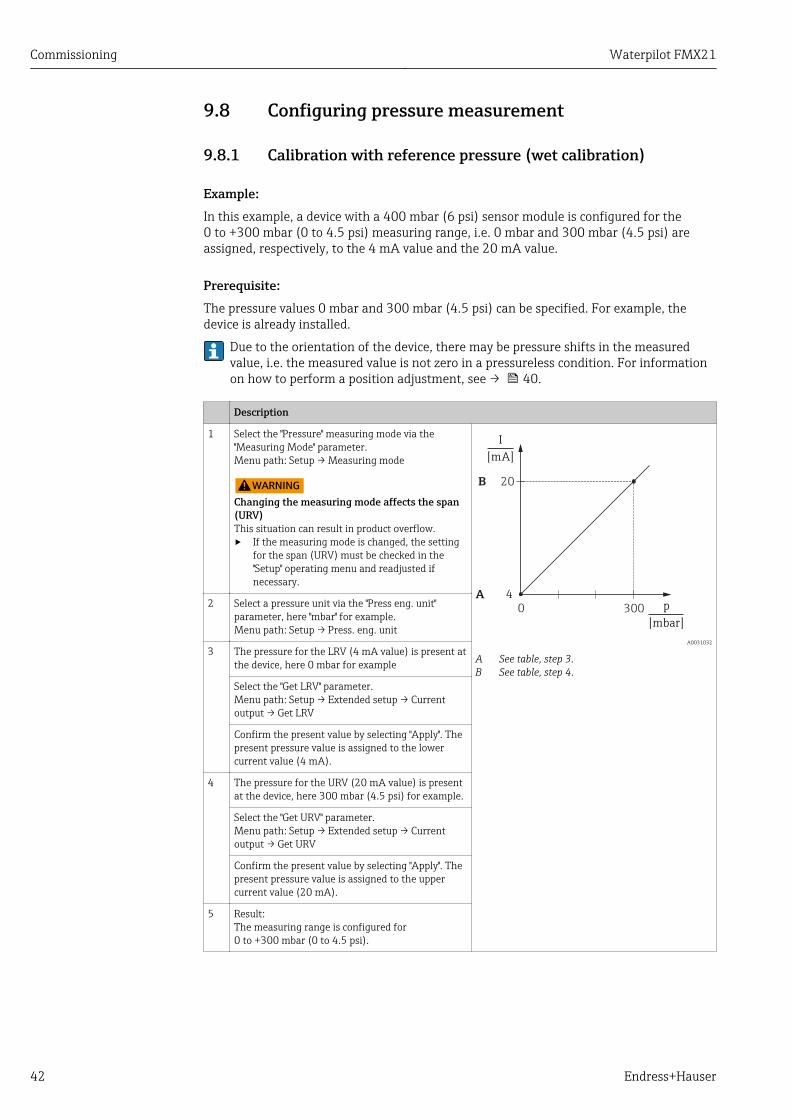
Example:In this example, a device with a 400 mbar (6 psi) sensor module is configured for the0 to +300 mbar (0 to 4.5 psi) measuring range, i.e. 0 mbar and 300 mbar (4.5 psi) areassigned, respectively, to the 4 mA value and the 20 mA value.
Prerequisite:The pressure values 0 mbar and 300 mbar (4.5 psi) can be specified. For example, thedevice is already installed.
Due to the orientation of the device, there may be pressure shifts in the measuredvalue, i.e. the measured value is not zero in a pressureless condition. For informationon how to perform a position adjustment, see → 40.
Description
1 Select the "Pressure" measuring mode via the"Measuring Mode" parameter.Menu path: Setup → Measuring mode
LWARNINGChanging the measuring mode affects the span(URV)This situation can result in product overflow.‣ If the measuring mode is changed, the setting
for the span (URV) must be checked in the"Setup" operating menu and readjusted ifnecessary.
p
[mbar]
20B
4A
0 300
I
[mA]
A0031032
A See table, step 3.B See table, step 4.
2 Select a pressure unit via the "Press eng. unit"parameter, here "mbar" for example.Menu path: Setup → Press. eng. unit
3 The pressure for the LRV (4 mA value) is present atthe device, here 0 mbar for example
Select the "Get LRV" parameter.Menu path: Setup → Extended setup → Currentoutput → Get LRV
Confirm the present value by selecting "Apply". Thepresent pressure value is assigned to the lowercurrent value (4 mA).
4 The pressure for the URV (20 mA value) is presentat the device, here 300 mbar (4.5 psi) for example.
Select the "Get URV" parameter.Menu path: Setup → Extended setup → Currentoutput → Get URV
Confirm the present value by selecting "Apply". Thepresent pressure value is assigned to the uppercurrent value (20 mA).
5 Result:The measuring range is configured for0 to +300 mbar (0 to 4.5 psi).

Waterpilot FMX21 Commissioning
Endress+Hauser 43
9.8.2 Calibration without reference pressure (dry calibration)
Example:In this example, a device with a 400 mbar (6 psi) sensor module is configured for the0 to +300 mbar (0 to 4.5 psi) measuring range, i.e. 0 mbar and 300 mbar (4.5 psi) areassigned, respectively, to the 4 mA value and the 20 mA value.
Prerequisite:This is a theoretical calibration, i.e. the pressure values for the lower and upper range areknown.
Due to the orientation of the device, there may be pressure shifts in the measuredvalue, i.e. the measured value is not zero in a pressureless condition. For informationon how to perform a position adjustment, see → 40.
Description
1 Select the "Pressure" measuring mode via the"Measuring Mode" parameter.Menu path: Setup → Measuring mode
LWARNINGChanging the measuring mode affects the span(URV)This situation can result in product overflow.‣ If the measuring mode is changed, the setting
for the span (URV) must be checked in the"Setup" operating menu and readjusted ifnecessary.
p
[mbar]
20B
4A
0 300
I
[mA]
A0031032
A See table, step 3.B See table, step 4.
2 Select a pressure unit via the "Press eng. unit"parameter, here "mbar" for example.Menu path: Setup → Press. eng. unit
3 Select the "Set LRV" parameter.Menu path: Setup → Extended setup → Currentoutput → Set LRV
Enter the value for the "Set LRV" parameter (here 0mbar) and confirm. This pressure value is assignedto the lower current value (4 mA).
4 Select the "Set URV" parameter.Menu path: Setup → Extended setup → Currentoutput → Set URV
Enter the value for the "Set URV" parameter, here300 mbar (4.5 psi), and confirm. This pressurevalue is assigned to the upper current value(20 mA).
5 Result:The measuring range is configured for0 to +300 mbar (0 to 4.5 psi).
Commissioning Waterpilot FMX21
44 Endress+Hauser
9.9 Configuring level measurement
9.9.1 Information on level measurementYou have a choice of two methods for calculating the level: "In pressure" and "Inheight". The table in the "Overview of level measurement" section that followsprovides you with an overview of these two measuring tasks.• The limit values are not checked, i.e. the values entered must be appropriate for the
sensor module and the measuring task for the device to be able to measurecorrectly.
• Customer-specific units are not possible.• The values entered for "Empty calib./Full calib.", "Empty pressure/Full pressure",
"Empty height/Full height" and "Set LRV/Set URV" must be at least 1% apart. Thevalue will be rejected, and a warning message displayed, if the values are too closetogether.
9.9.2 Overview of level measurement
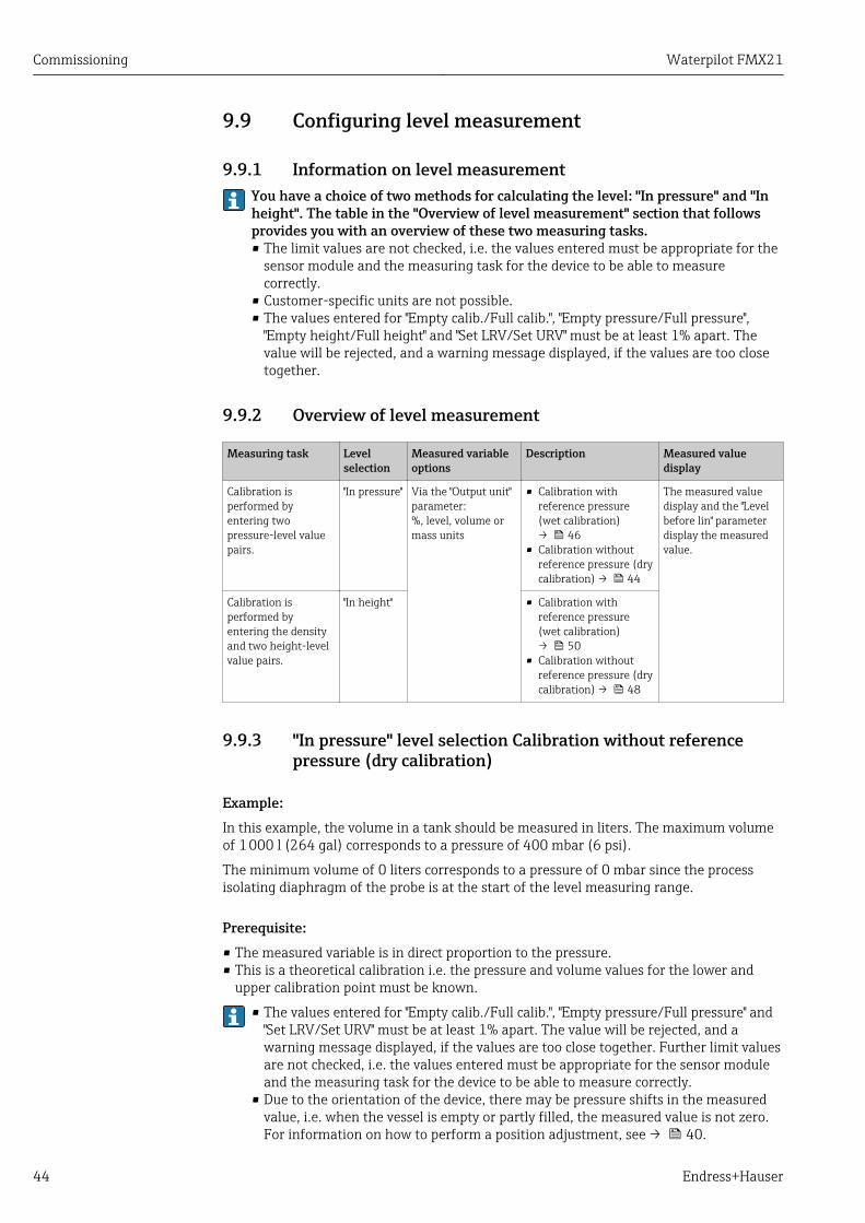
Measuring task Levelselection
Measured variableoptions
Description Measured valuedisplay
Calibration isperformed byentering twopressure-level valuepairs.
"In pressure" Via the "Output unit"parameter:%, level, volume ormass units
• Calibration withreference pressure(wet calibration)→ 46
• Calibration withoutreference pressure (drycalibration) → 44
The measured valuedisplay and the "Levelbefore lin" parameterdisplay the measuredvalue.
Calibration isperformed byentering the densityand two height-levelvalue pairs.
"In height" • Calibration withreference pressure(wet calibration)→ 50
• Calibration withoutreference pressure (drycalibration) → 48
9.9.3 "In pressure" level selection Calibration without referencepressure (dry calibration)
Example:In this example, the volume in a tank should be measured in liters. The maximum volumeof 1 000 l (264 gal) corresponds to a pressure of 400 mbar (6 psi).
The minimum volume of 0 liters corresponds to a pressure of 0 mbar since the processisolating diaphragm of the probe is at the start of the level measuring range.
Prerequisite:• The measured variable is in direct proportion to the pressure.• This is a theoretical calibration i.e. the pressure and volume values for the lower and
upper calibration point must be known.
• The values entered for "Empty calib./Full calib.", "Empty pressure/Full pressure" and"Set LRV/Set URV" must be at least 1% apart. The value will be rejected, and awarning message displayed, if the values are too close together. Further limit valuesare not checked, i.e. the values entered must be appropriate for the sensor moduleand the measuring task for the device to be able to measure correctly.
• Due to the orientation of the device, there may be pressure shifts in the measuredvalue, i.e. when the vessel is empty or partly filled, the measured value is not zero.For information on how to perform a position adjustment, see → 40.
Waterpilot FMX21 Commissioning
Endress+Hauser 45
Description
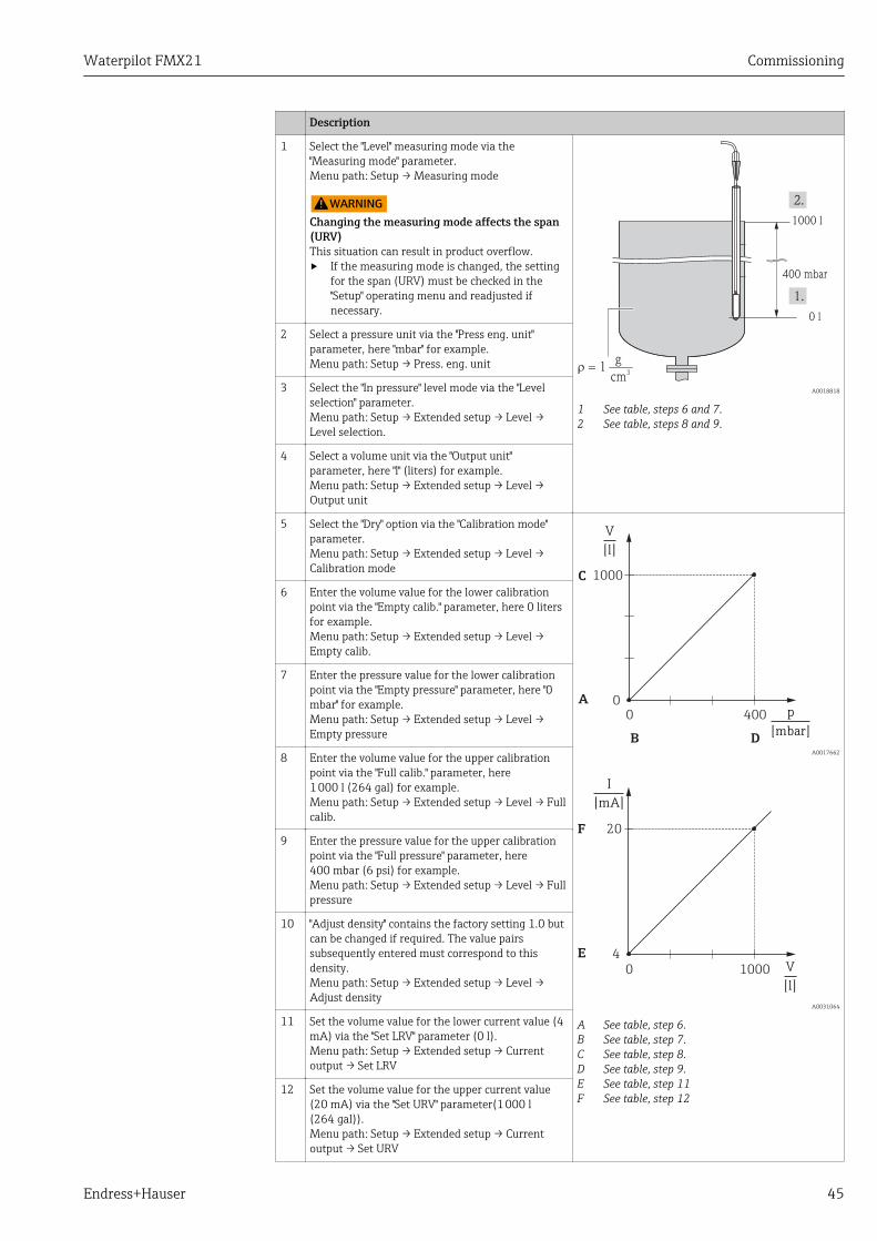
1 Select the "Level" measuring mode via the"Measuring mode" parameter.Menu path: Setup → Measuring mode
LWARNINGChanging the measuring mode affects the span(URV)This situation can result in product overflow.‣ If the measuring mode is changed, the setting
for the span (URV) must be checked in the"Setup" operating menu and readjusted ifnecessary.
1000 l
0 l
400 mbar
r = 1g
cm3
A0018818
1 See table, steps 6 and 7.2 See table, steps 8 and 9.
2 Select a pressure unit via the "Press eng. unit"parameter, here "mbar" for example.Menu path: Setup → Press. eng. unit
3 Select the "In pressure" level mode via the "Levelselection" parameter.Menu path: Setup → Extended setup → Level →Level selection.
4 Select a volume unit via the "Output unit"parameter, here "l" (liters) for example.Menu path: Setup → Extended setup → Level →Output unit
5 Select the "Dry" option via the "Calibration mode"parameter.Menu path: Setup → Extended setup → Level →Calibration mode
A
B
C
D
V
[l]
p
[mbar]
1000
00 400
A0017662
E
F
I
[mA]
V
[l]
20
4
0 1000
A0031064
A See table, step 6.B See table, step 7.C See table, step 8.D See table, step 9.E See table, step 11F See table, step 12
6 Enter the volume value for the lower calibrationpoint via the "Empty calib." parameter, here 0 litersfor example.Menu path: Setup → Extended setup → Level →Empty calib.
7 Enter the pressure value for the lower calibrationpoint via the "Empty pressure" parameter, here "0mbar" for example.Menu path: Setup → Extended setup → Level →Empty pressure
8 Enter the volume value for the upper calibrationpoint via the "Full calib." parameter, here1 000 l (264 gal) for example.Menu path: Setup → Extended setup → Level → Fullcalib.
9 Enter the pressure value for the upper calibrationpoint via the "Full pressure" parameter, here400 mbar (6 psi) for example.Menu path: Setup → Extended setup → Level → Fullpressure
10 "Adjust density" contains the factory setting 1.0 butcan be changed if required. The value pairssubsequently entered must correspond to thisdensity.Menu path: Setup → Extended setup → Level →Adjust density
11 Set the volume value for the lower current value (4mA) via the "Set LRV" parameter (0 l).Menu path: Setup → Extended setup → Currentoutput → Set LRV
12 Set the volume value for the upper current value(20 mA) via the "Set URV" parameter(1 000 l(264 gal)).Menu path: Setup → Extended setup → Currentoutput → Set URV
Commissioning Waterpilot FMX21
46 Endress+Hauser
Description
13 If the process uses a medium other than that onwhich the calibration was based, the new densitymust be specified in the "Process density"parameter.Menu path: Setup → Extended setup → Currentoutput → Process density.
14 If density correction is required, assign thetemperature probe in the "Auto dens. corr."parameter. A density correction is only possible forwater. A temperature-density curve that is saved inthe device is used. For this reason, the "Adjustdensity" (step 10) and "Process density" (step 13)parameters are not used here.Menu path: Expert → Application → Level → Autodens. corr.
15 Result:The measuring range is configured for0 to 1 000 l (0 to 264 gal).
For this level mode, the measured variables %, level, volume and mass are available,see "Output unit" → 87.
9.9.4 "In pressure" level selection Calibration with referencepressure (wet calibration)
Example:In this example, the level in a tank should be measured in "m". The maximum level is3 m (9.8 ft).
The pressure range is derived from the level and the density of the medium. In thissituation, the device sets the pressure range to 0 to +300 mbar (0 to 4.5 psi).
Prerequisite:• The measured variable is in direct proportion to the pressure.• The tank can be filled and emptied.
The values entered for "Empty calib./Full calib." and" Set LRV/Set URV" and thepressures present must be at least 1% apart. The value will be rejected, and a warningmessage displayed, if the values are too close together. Other limit values are notchecked, i.e. the values entered must be appropriate for the sensor and the measuringtask for the device to be able to measure correctly.

Waterpilot FMX21 Commissioning
Endress+Hauser 47
Description
1 Perform a "position adjustment" → 40.
0 mbar
300 mbar
3 m
0 m
A0018824
1 See table, step 9.2 See table, step 10.
2 Select the "Level" measuring mode via the"Measuring mode" parameter.Menu path: Setup → Measuring mode
LWARNINGChanging the measuring mode affects the span(URV)This situation can result in product overflow.‣ If the measuring mode is changed, the setting
for the span (URV) must be checked in the"Setup" operating menu and readjusted ifnecessary.
3 Select a pressure unit via the "Press eng. unit"parameter, here "mbar" for example.Menu path: Setup → Press. eng. unit
4 Select the "In pressure" level mode via the "Levelselection" parameter.Menu path: Setup → Extended setup → Level →Level selection.
5 If density correction is required, assign thetemperature probe in the "Auto dens. corr."parameter.Menu path: Expertc → Application → Auto dens.corr.A density correction is only possible for water. Atemperature-density curve that is saved in thedevice is used. For this reason, the "Adjust density"(step 8) and "Process density" (step 13) parametersare not used here.
6 Select a level unit via the "Output unit" parameter,here "m" for example.Menu path: Setup → Extended setup → Level →Output unit
7 Select the "Wet" option via the "Calibration mode"parameter.Menu path: Setup → Extended setup → Level →Calibration mode
A
B
h
[m]
p
[mbar]
3
00 300
A0017658
C
D
I
[mA]
h
[m]
20
4
0 3
A0031063
A See table, step 9.B See table, step 10.C See table, step 11.D See table, step 12.
8 If the calibration is performed with a medium otherthan the process medium, enter the density of thecalibration medium in the "Adjust density"parameter.Menu path: Setup → Extended setup → Level →Adjust density
The process density can be changed only ifautomatic density correction is switched off(see step 5).
9 The hydrostatic pressure for the lower calibrationpoint is present at the device, here "0 mbar" forexample.
Select the "Empty calib." parameter.Menu path: Setup → Extended setup → Level →Empty calib.
Enter the level value, here 0 m for example. Thepressure value present is assigned to the lowerlevel value by confirming the value.
10 The hydrostatic pressure for the upper calibrationpoint is present at the device, here300 mbar (4.35 psi) for example.

Commissioning Waterpilot FMX21
48 Endress+Hauser
Description
Select the "Full calib." parameter.Menu path: Setup → Extended setup → Level → Fullcalib.
Enter the level value, here 3 m (9.8 ft) for example.The pressure value present is assigned to the upperlevel value by confirming the value.
11 Use the "Set LRV" parameter to set the level valuefor the lower current value (4 mA), here "0 m" forexample.Menu path: Setup → Extended setup → Currentoutput → Set LRV
12 Use the "Set URV" parameter to set the uppercurrent value (20 mA) (3 m (9.8 ft)).Menu path: Setup → Extended setup → Currentoutput → Set URV
12 If the process uses a medium other than that onwhich the calibration was based, the new densitymust be specified in the "Process density"parameter.Menu path: Setup → Extended setup → Level →Process density.
The process density can be changed only ifautomatic density correction is switched off(see step 5).
13 Result:The measuring range is configured for0 to 3 m (0 to 9.8 ft).
For this level mode, the measured variables %, level, volume and mass are available,see "Output unit" → 87.
9.9.5 "In height" level selection Calibration without referencepressure (dry calibration)
Example:In this example, the volume in a tank should be measured in liters. The maximum volumeof 1 000 l (264 gal) corresponds to a level of 4 m (13 ft). The minimum volume of 0 litercorresponds to a level of 0 m since the process isolating diaphragm of the probe is at thestart of the level measuring range.
Prerequisite:• The measured variable is in direct proportion to the pressure.• This is a theoretical calibration i.e. the height and volume values for the lower and upper
calibration point must be known.
• The values entered for "Empty calib./Full calib.", "Empty height/Full height" and" SetLRV/Set URV" must be at least 1% apart. The value will be rejected, and a warningmessage displayed, if the values are too close together. Other limit values are notchecked, i.e. the values entered must be appropriate for the sensor and themeasuring task for the device to be able to measure correctly.
• Due to the orientation of the device, there may be pressure shifts in the measuredvalue, i.e. when the vessel is empty or partly filled, the measured value is not zero.For information on how to perform a position adjustment, see → 40.
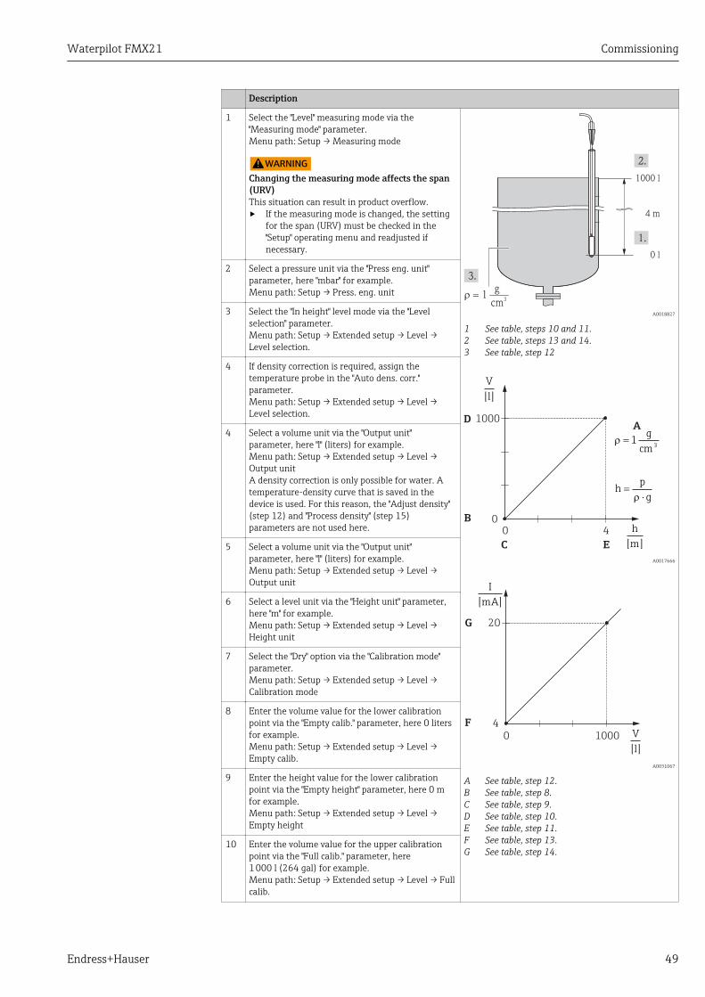
Waterpilot FMX21 Commissioning
Endress+Hauser 49
Description
1 Select the "Level" measuring mode via the"Measuring mode" parameter.Menu path: Setup → Measuring mode
LWARNINGChanging the measuring mode affects the span(URV)This situation can result in product overflow.‣ If the measuring mode is changed, the setting
for the span (URV) must be checked in the"Setup" operating menu and readjusted ifnecessary.
1000 l
0 l
4 m
r = 1g
cm3
A0018827
1 See table, steps 10 and 11.2 See table, steps 13 and 14.3 See table, step 12
A
hp
g=
×r
r = 1g
cm 3
B
D
C E
V
[l]
h
[m]
1000
00 4
A0017666
F
G
I
[mA]
V
[l]
20
4
0 1000
A0031067
A See table, step 12.B See table, step 8.C See table, step 9.D See table, step 10.E See table, step 11.F See table, step 13.G See table, step 14.
2 Select a pressure unit via the "Press eng. unit"parameter, here "mbar" for example.Menu path: Setup → Press. eng. unit
3 Select the "In height" level mode via the "Levelselection" parameter.Menu path: Setup → Extended setup → Level →Level selection.
4 If density correction is required, assign thetemperature probe in the "Auto dens. corr."parameter.Menu path: Setup → Extended setup → Level →Level selection.
4 Select a volume unit via the "Output unit"parameter, here "l" (liters) for example.Menu path: Setup → Extended setup → Level →Output unitA density correction is only possible for water. Atemperature-density curve that is saved in thedevice is used. For this reason, the "Adjust density"(step 12) and "Process density" (step 15)parameters are not used here.
5 Select a volume unit via the "Output unit"parameter, here "l" (liters) for example.Menu path: Setup → Extended setup → Level →Output unit
6 Select a level unit via the "Height unit" parameter,here "m" for example.Menu path: Setup → Extended setup → Level →Height unit
7 Select the "Dry" option via the "Calibration mode"parameter.Menu path: Setup → Extended setup → Level →Calibration mode
8 Enter the volume value for the lower calibrationpoint via the "Empty calib." parameter, here 0 litersfor example.Menu path: Setup → Extended setup → Level →Empty calib.
9 Enter the height value for the lower calibrationpoint via the "Empty height" parameter, here 0 mfor example.Menu path: Setup → Extended setup → Level →Empty height
10 Enter the volume value for the upper calibrationpoint via the "Full calib." parameter, here1 000 l (264 gal) for example.Menu path: Setup → Extended setup → Level → Fullcalib.

Commissioning Waterpilot FMX21
50 Endress+Hauser
Description
11 Enter the height value for the upper calibrationpoint via the "Full height" parameter, here4 m (13 ft) for example.Menu path: Setup → Extended setup → Level → Fullheight
12 Enter the density of the medium via the "Adjustdensity" parameter, here "1 g/cm3" (1 SGU) forexample.Menu path: Setup → Extended setup → Level →Adjust density
13 Set the volume value for the lower current value (4mA) via the "Set LRV" parameter (0 l).Menu path: Setup → Extended setup → Currentoutput → Set LRV
14 Set the volume value for the upper current value(20 mA) via the "Set URV" parameter (1 000 l(264 gal)).Menu path: Setup → Extended setup → Currentoutput → Set URV
15 If the process uses a medium other than that onwhich the calibration was based, the new densitymust be specified in the "Process density"parameter.Menu path: Setup → Extended setup → Currentoutput → Process density.
The process density can only be changed ifautomatic density correction is switched off(see Step 4).
16 Result:The measuring range is configured for0 to 1 000 l (0 to 264 gal).
For this level mode, the measured variables %, level, volume and mass are available,see "Output unit" → 87.
9.9.6 "In height" level selection Calibration with reference pressure(wet calibration)
Example:In this example, the volume in a tank should be measured in liters. The maximum volumeof 1 000 l (264 gal) corresponds to a level of 4 m (13 ft).
The minimum volume of 0 liter corresponds to a level of 0 m since the process isolatingdiaphragm of the probe is at the start of the level measuring range. The density of thefluid is 1 g/cm3 (1 SGU).
Prerequisite:• The measured variable is in direct proportion to the pressure.• The tank can be filled and emptied.
The values entered for "Empty calib./Full calib." and" Set LRV/Set URV" and thepressures present must be at least 1% apart. The value will be rejected, and a warningmessage displayed, if the values are too close together. Other limit values are notchecked, i.e. the values entered must be appropriate for the sensor and the measuringtask for the device to be able to measure correctly.

Waterpilot FMX21 Commissioning
Endress+Hauser 51
Description
1 Perform a "position adjustment" → 40.
1000 l
0 l
4 m
r = 1g
cm3
A0018827
1 See table, step 9.2 See table, step 10.3 See table, step 11.
2 Select the "Level" measuring mode via the"Measuring mode" parameter.Menu path: Setup → Measuring mode
LWARNINGChanging the measuring mode affects the span(URV)This situation can result in product overflow.‣ If the measuring mode is changed, the setting
for the span (URV) must be checked in the"Setup" operating menu and readjusted ifnecessary.
3 Select the "In height" level mode via the "Levelselection" parameter.Menu path: Setup → Extended setup → Level →Level selection.
4 If density correction is required, assign thetemperature probe in the "Auto dens. corr."parameter.Menu path: Expertc → Application → Auto dens.corr.A density correction is only possible for water. Atemperature-density curve that is saved in thedevice is used. For this reason, the "Adjust density"(step 11) and "Process density" (step 14)parameters are not used here.
5 Select a pressure unit via the "Press eng. unit"parameter, here "mbar" for example.Menu path: Setup → Press. eng. unit A
hp
g=
×r
r = 1g
cm 3
B
D
C E
V
[l]
1000
00 p
[mbar]
400
A0031097
F
G
I
[mA]
V
[l]
20
4
0 1000
A0031067
A See table, step 11.B See table, step 9.C See table, step 9.D See table, step 10.
6 Select a volume unit via the "Output unit"parameter, here "l" (liters) for exampleMenu path: Setup → Extended setup → Level →Output unit
7 Select a height unit via the "Height unit" parameter,here "m" for example.Menu path: Setup → Extended setup → Level →Height unit
8 Select the "Wet" option via the "Calibration mode"parameter.Menu path: Setup → Extended setup → Level →Calibration mode
9 The hydrostatic pressure for the lower calibrationpoint is present at the device, here "0 mbar" forexample.
Enter the volume value for the lower calibrationpoint via the "Empty calib." parameter, here "0 liters"for example.Menu path: Setup → Extended setup → Level →Empty calib.
10 The hydrostatic pressure for the upper calibrationpoint is present at the device, here "400 mbar(6 psi)" for example.
Enter the volume value for the upper calibrationpoint via the "Full calib." parameter, here1 000 l (264 gal) for example.Menu path: Setup → Extended setup → Level → Fullcalib.

Commissioning Waterpilot FMX21
52 Endress+Hauser
Description
11 If the calibration is performed with a medium otherthan the process medium, enter the density of thecalibration medium in the "Adjust density"parameter, here 1 g/cm3 (1 SGU) for example.Menu path: Setup → Extended setup → Level →Adjust density
The process density can only be changed ifautomatic density correction is switched off(see Step 4).
E See table, step 10.F See table, step 12.G See table, step 13.
12 Set the volume value for the lower current value (4mA) via the "Set LRV" parameter (0 l).Menu path: Setup → Extended setup → Currentoutput → Set LRV
13 Set the volume value for the upper current value(20 mA) via the "Set URV" parameter(1 000 l(264 gal)).Menu path: Setup → Extended setup → Currentoutput → Set URV
14 If the process uses a medium other than that onwhich the calibration was based, the new densitymust be specified in the "Process density"parameter.Menu path: Setup → Extended setup → Level →Process density.
The process density can only be changed ifautomatic density correction is switched off(see Step 4).
15 Result:The measuring range is configured for0 to 1 000 l (0 to 264 gal).
For this level mode, the measured variables %, level, volume and mass are available,see "Output unit" .
9.9.7 Calibration with partially filled vessel (wet calibration)
Example:This example explains a wet calibration for cases in which it is not possible to empty thevessel and then fill it to 100%.
During this wet calibration, a level of 20% is used as the calibration point for "Empty" and alevel of "25%" is used as the calibration point for "Full".
The calibration is then extended to 0% to 100% and lower range-value (LRV)/upperrange-value (URV) are adapted accordingly.
Prerequisite:• The default value in level mode for the calibration mode is "Wet".• This value can be adjusted: Menu path: Setup → Extended setup → Level → Calibration
mode
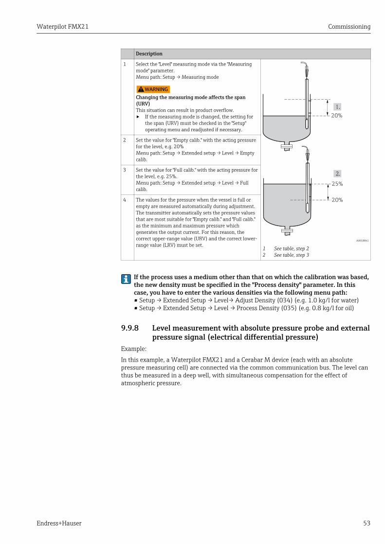
Waterpilot FMX21 Commissioning
Endress+Hauser 53
Description
1 Select the "Level" measuring mode via the "Measuringmode" parameter.Menu path: Setup → Measuring mode
LWARNINGChanging the measuring mode affects the span(URV)This situation can result in product overflow.‣ If the measuring mode is changed, the setting for
the span (URV) must be checked in the "Setup"operating menu and readjusted if necessary.
20%
20%
25%
A0018841
1 See table, step 22 See table, step 3
2 Set the value for "Empty calib." with the acting pressurefor the level, e.g. 20%Menu path: Setup → Extended setup → Level → Emptycalib.
3 Set the value for "Full calib." with the acting pressure forthe level, e.g. 25%.Menu path: Setup → Extended setup → Level → Fullcalib.
4 The values for the pressure when the vessel is full orempty are measured automatically during adjustment.The transmitter automatically sets the pressure valuesthat are most suitable for "Empty calib." and "Full calib."as the minimum and maximum pressure whichgenerates the output current. For this reason, thecorrect upper-range value (URV) and the correct lower-range value (LRV) must be set.
If the process uses a medium other than that on which the calibration was based,the new density must be specified in the "Process density" parameter. In thiscase, you have to enter the various densities via the following menu path:• Setup → Extended Setup → Level→ Adjust Density (034) (e.g. 1.0 kg/l for water)• Setup → Extended Setup → Level → Process Density (035) (e.g. 0.8 kg/l for oil)
9.9.8 Level measurement with absolute pressure probe and externalpressure signal (electrical differential pressure)
Example:
In this example, a Waterpilot FMX21 and a Cerabar M device (each with an absolutepressure measuring cell) are connected via the common communication bus. The level canthus be measured in a deep well, with simultaneous compensation for the effect ofatmospheric pressure.
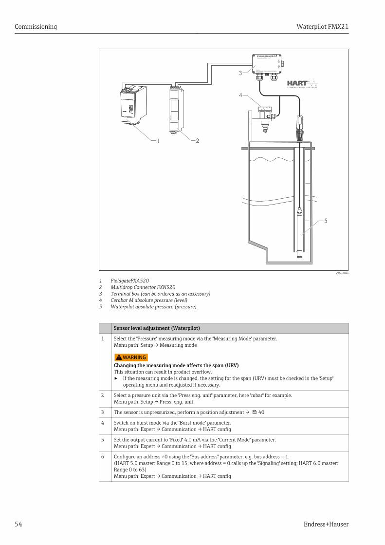
Commissioning Waterpilot FMX21
54 Endress+Hauser
FX
N520
OPEN
CLOSE
90°
90°
Warning:Avoid electrostatic charge in explosive atmosphere.See instructions
Terminal Box for FMX21
1 2
4
3
5
A0018821
1 FieldgateFXA5202 Multidrop Connector FXN5203 Terminal box (can be ordered as an accessory)4 Cerabar M absolute pressure (level)5 Waterpilot absolute pressure (pressure)
Sensor level adjustment (Waterpilot)
1 Select the "Pressure" measuring mode via the "Measuring Mode" parameter.Menu path: Setup → Measuring mode
LWARNINGChanging the measuring mode affects the span (URV)This situation can result in product overflow.‣ If the measuring mode is changed, the setting for the span (URV) must be checked in the "Setup"
operating menu and readjusted if necessary.
2 Select a pressure unit via the "Press eng. unit" parameter, here "mbar" for example.Menu path: Setup → Press. eng. unit
3 The sensor is unpressurized, perform a position adjustment → 40
4 Switch on burst mode via the "Burst mode" parameter.Menu path: Expert → Communication → HART config
5 Set the output current to "Fixed" 4.0 mA via the "Current Mode" parameter.Menu path: Expert → Communication → HART config
6 Configure an address ≠0 using the "Bus address" parameter, e.g. bus address = 1.(HART 5.0 master: Range 0 to 15, where address = 0 calls up the "Signaling" setting; HART 6.0 master:Range 0 to 63)Menu path: Expert → Communication → HART config
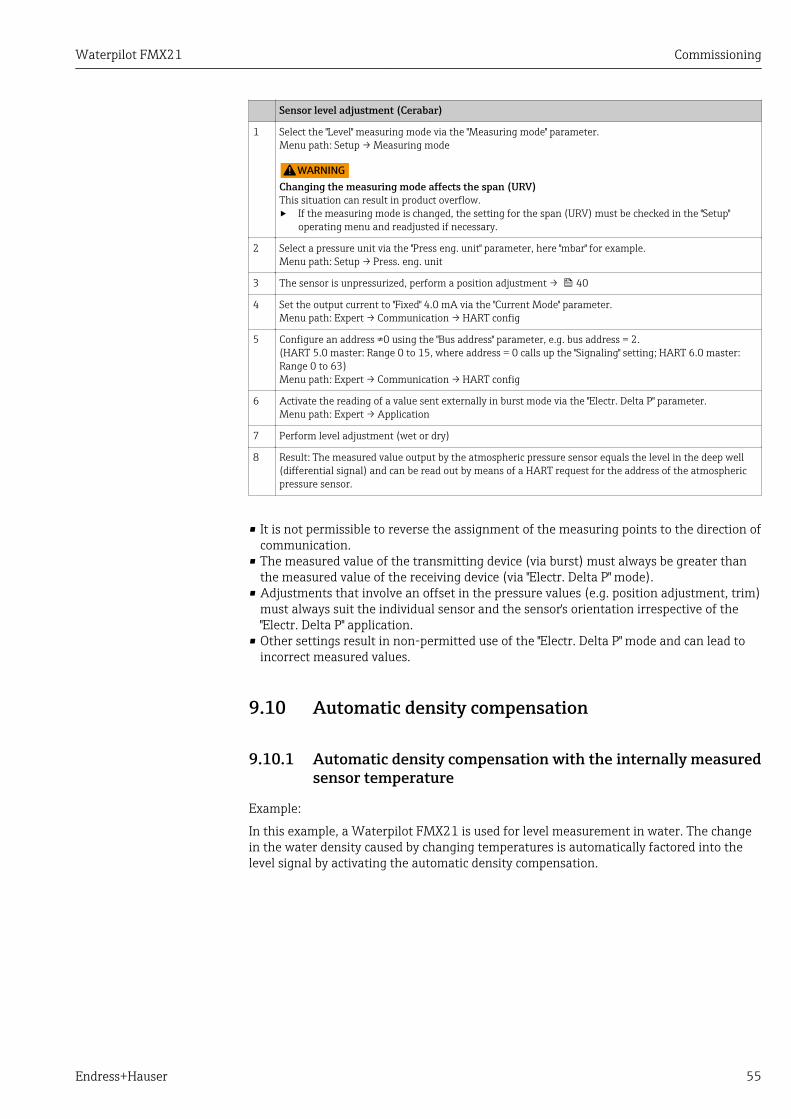
Waterpilot FMX21 Commissioning
Endress+Hauser 55
Sensor level adjustment (Cerabar)
1 Select the "Level" measuring mode via the "Measuring mode" parameter.Menu path: Setup → Measuring mode
LWARNINGChanging the measuring mode affects the span (URV)This situation can result in product overflow.‣ If the measuring mode is changed, the setting for the span (URV) must be checked in the "Setup"
operating menu and readjusted if necessary.
2 Select a pressure unit via the "Press eng. unit" parameter, here "mbar" for example.Menu path: Setup → Press. eng. unit
3 The sensor is unpressurized, perform a position adjustment → 40
4 Set the output current to "Fixed" 4.0 mA via the "Current Mode" parameter.Menu path: Expert → Communication → HART config
5 Configure an address ≠0 using the "Bus address" parameter, e.g. bus address = 2.(HART 5.0 master: Range 0 to 15, where address = 0 calls up the "Signaling" setting; HART 6.0 master:Range 0 to 63)Menu path: Expert → Communication → HART config
6 Activate the reading of a value sent externally in burst mode via the "Electr. Delta P" parameter.Menu path: Expert → Application
7 Perform level adjustment (wet or dry)
8 Result: The measured value output by the atmospheric pressure sensor equals the level in the deep well(differential signal) and can be read out by means of a HART request for the address of the atmosphericpressure sensor.
• It is not permissible to reverse the assignment of the measuring points to the direction ofcommunication.
• The measured value of the transmitting device (via burst) must always be greater thanthe measured value of the receiving device (via "Electr. Delta P" mode).
• Adjustments that involve an offset in the pressure values (e.g. position adjustment, trim)must always suit the individual sensor and the sensor's orientation irrespective of the"Electr. Delta P" application.
• Other settings result in non-permitted use of the "Electr. Delta P" mode and can lead toincorrect measured values.
9.10 Automatic density compensation
9.10.1 Automatic density compensation with the internally measuredsensor temperature
Example:
In this example, a Waterpilot FMX21 is used for level measurement in water. The changein the water density caused by changing temperatures is automatically factored into thelevel signal by activating the automatic density compensation.

Commissioning Waterpilot FMX21
56 Endress+Hauser
1
2
A0018822
1 HART master, e.g. PLC (programmable logic controller)2 Waterpilot FMX21
Waterpilot adjustment for level measurement
1 Select the "Level" measuring mode via the "Measuring mode" parameter.Menu path: Setup → Measuring mode
LWARNINGChanging the measuring mode affects the span (URV)This situation can result in product overflow.‣ If the measuring mode is changed, the setting for the span (URV) must be checked in the "Setup"
operating menu and readjusted if necessary.
2 Select a pressure unit via the "Press eng. unit" parameter, here "mbar" for example.Menu path: Setup → Press. eng. unit
3 The sensor is unpressurized, perform a position adjustment → 40
4 Set the "Auto dens. corr." parameter to Sensor temperature.Menu path: Expert → Application
5 Perform level adjustment (wet or dry)
6 Result: The measured value output by the Waterpilot corresponds to the level in the deep well correctedby means of the density characteristic line of water.
9.10.2 Automatic density compensation using an integrated Pt100for calculation in a suitable HART master (e.g. PLC)
Example:
In this example, the FMX21 with an integrated Pt100 is connected via the commoncommunication bus to any temperature head transmitter with HART communication (e.g.TMT182). The temperature and pressure signal is transmitted to the HART master (e.g.PLC), where a corrected level value can be generated using a stored linearization table ordensity function (of a chosen medium). A pressure signal and a temperature signal canthus be generated with a chosen density function to compensate for a level.
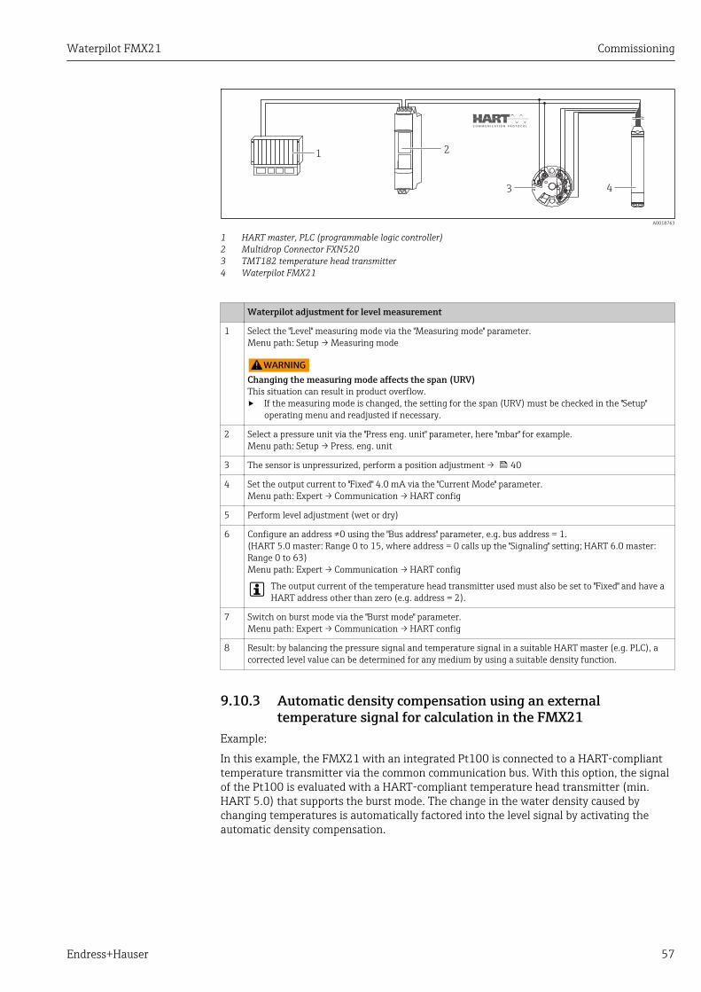
Waterpilot FMX21 Commissioning
Endress+Hauser 57
12
3 4
FX
N520
A0018763
1 HART master, PLC (programmable logic controller)2 Multidrop Connector FXN5203 TMT182 temperature head transmitter4 Waterpilot FMX21
Waterpilot adjustment for level measurement
1 Select the "Level" measuring mode via the "Measuring mode" parameter.Menu path: Setup → Measuring mode
LWARNINGChanging the measuring mode affects the span (URV)This situation can result in product overflow.‣ If the measuring mode is changed, the setting for the span (URV) must be checked in the "Setup"
operating menu and readjusted if necessary.
2 Select a pressure unit via the "Press eng. unit" parameter, here "mbar" for example.Menu path: Setup → Press. eng. unit
3 The sensor is unpressurized, perform a position adjustment → 40
4 Set the output current to "Fixed" 4.0 mA via the "Current Mode" parameter.Menu path: Expert → Communication → HART config
5 Perform level adjustment (wet or dry)
6 Configure an address ≠0 using the "Bus address" parameter, e.g. bus address = 1.(HART 5.0 master: Range 0 to 15, where address = 0 calls up the "Signaling" setting; HART 6.0 master:Range 0 to 63)Menu path: Expert → Communication → HART config
The output current of the temperature head transmitter used must also be set to "Fixed" and have aHART address other than zero (e.g. address = 2).
7 Switch on burst mode via the "Burst mode" parameter.Menu path: Expert → Communication → HART config
8 Result: by balancing the pressure signal and temperature signal in a suitable HART master (e.g. PLC), acorrected level value can be determined for any medium by using a suitable density function.
9.10.3 Automatic density compensation using an externaltemperature signal for calculation in the FMX21
Example:
In this example, the FMX21 with an integrated Pt100 is connected to a HART-complianttemperature transmitter via the common communication bus. With this option, the signalof the Pt100 is evaluated with a HART-compliant temperature head transmitter (min.HART 5.0) that supports the burst mode. The change in the water density caused bychanging temperatures is automatically factored into the level signal by activating theautomatic density compensation.

Commissioning Waterpilot FMX21
58 Endress+Hauser
FX
N520
4
12
3
A0018764
1 FieldgateFXA5202 Multidrop Connector FXN5203 HART-compatible temperature transmitter (e.g. TMT82)4 Waterpilot FMX21
Configuring the HART-compliant temperature head transmitter (min. HART 5.0) with burstfunction
The output current of the temperature transmitter used should be set to "Fixed" and a HART address otherthan zero (e.g. address = 1) must be set. The burst function must then be switched on with HARTcommand 1. This step should be performed before the procedure described below in order to avoid aHART input error of the FMX21 being output during commissioning.
1 Select the "Level" measuring mode via the "Measuring mode" parameter.Menu path: Setup → Measuring mode
LWARNINGChanging the measuring mode affects the span (URV)This situation can result in product overflow.‣ If the measuring mode is changed, the setting for the span (URV) must be checked in the "Setup"
operating menu and readjusted if necessary.
2 Select a pressure unit via the "Press eng. unit" parameter, here "mbar" for example.Menu path: Setup → Press. eng. unit
3 The sensor is unpressurized, perform a position adjustment → 40
4 Set the "Auto dens. corr." parameter to "External value".Menu path: Expert → Application
5 Perform level adjustment (wet or dry)
Result: The measured value output by the Waterpilot corresponds to the level in the deep well correctedby means of the density characteristic line of water.
The TMT182 temperature head transmitter is not suitable for this configuration.
9.11 Linearization
9.11.1 Semi-automatic entry of a linearization table
Example:In this example, the volume in a tank with a conical outlet should be measured in m3.
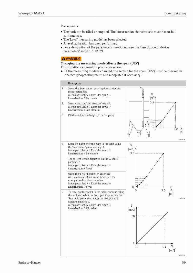
Waterpilot FMX21 Commissioning
Endress+Hauser 59
Prerequisite:• The tank can be filled or emptied. The linearization characteristic must rise or fall
continuously.• The "Level" measuring mode has been selected.• A level calibration has been performed.• For a description of the parameters mentioned, see the "Description of device
parameters" section → 79.
LWARNINGChanging the measuring mode affects the span (URV)This situation can result in product overflow.‣ If the measuring mode is changed, the setting for the span (URV) must be checked in
the "Setup" operating menu and readjusted if necessary.
Description
1 Select the "Semiautom. entry" option via the "Lin.mode" parameter.Menu path: Setup → Extended setup →Linearization → Lin. mode
3.5
0 3.0
V[m ]
3
h[m]
0
A0018843
2 Select using the "Unit after lin." e.g. m3.Menu path: Setup → Extended setup →Linearization →Unit after lin.
3 Fill the tank to the height of the 1st point.
4 Enter the number of the point in the table usingthe "Line-numb" parameter e.g. 1.Menu path: Setup → Extended setup →Linearization → Line numb
h
[m]
3.5
00 3.0
V
[m 3]
A0031098
V
[m ]3
20
4
0 3.5
I
[mA]
A0031031
The current level is displayed via the "X-value"parameter.Menu path: Setup → Extended setup →Linearization → X-val
Using the "Y-val." parameter, enter thecorresponding volume value, here 0 m3 forexample, and confirm the value.Menu path: Setup → Extended setup →Linearization → Y-val
5 To enter another point in the table, continue fillingthe tank and select the "Next point" option via the"Edit table" parameter. Enter the next point asexplained in Step 4.Menu path: Setup → Extended setup →Linearization → Edit table

Commissioning Waterpilot FMX21
60 Endress+Hauser
Description
6 Once all the points have been entered in the table,select the "Activate table" option via the "Lin. mode"parameter.Menu path: Setup → Extended setup →Linearization → Lin. mode
7 Result:Result: The measured value after linearization isdisplayed.
• Error message F510 "Linearization" and alarm current as long as the table is beingentered and until the table is activated.
• The lower-range value (= 4mA) is defined by the smallest point in the table.The upper-range value (= 20mA) is defined by the largest point in the table.
• Using the parameters "Set LRV" and "Set URV", you can change the allocation of thevolume/mass values to the current values.
9.11.2 Manual entry of a linearization table
Example:In this example, the volume in a tank with a conical outlet should be measured in m3.
Prerequisite:• This is a theoretical calibration, i.e. the points for the linearization table are known.• The "Level" measuring mode has been selected.• A level calibration has been performed.• The linearization characteristic must rise or fall continuously.• For a description of the parameters mentioned, see the "Description of device
parameters" section → 79.
LWARNINGChanging the measuring mode affects the span (URV)This situation can result in product overflow.‣ If the measuring mode is changed, the setting for the span (URV) must be checked in
the "Setup" operating menu and readjusted if necessary.
Description
1 Select the "Manual entry" option via the "Lin. mode"parameter.Menu path: Setup → Extended setup →Linearization → Lin. mode
3.5
0 3.0
V[m ]
3
h[m]
0
A0018843
2 Select using the "Unit after lin." e.g. m3.Menu path: Setup → Extended Setup →Linearisierung → Einheit n. Lin.
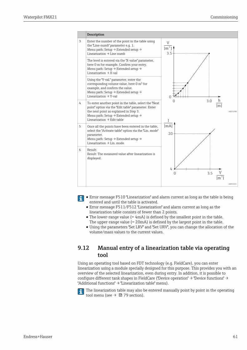
Waterpilot FMX21 Commissioning
Endress+Hauser 61
Description
3 Enter the number of the point in the table usingthe "Line-numb" parameter e.g. 1.Menu path: Setup → Extended setup →Linearization → Line numb
h
[m]
3.5
00 3.0
V
[m 3]
A0031098
V
[m ]3
20
4
0 3.5
I
[mA]
A0031031
The level is entered via the "X-value" parameter,here 0 m for example. Confirm your entry.Menu path: Setup → Extended setup →Linearization → X-val
Using the "Y-val." parameter, enter thecorresponding volume value, here 0 m3 forexample, and confirm the value.Menu path: Setup → Extended setup →Linearization → Y-val
4 To enter another point in the table, select the "Nextpoint" option via the "Edit table" parameter. Enterthe next point as explained in Step 3.Menu path: Setup → Extended setup →Linearization → Edit table
5 Once all the points have been entered in the table,select the "Activate table" option via the "Lin. mode"parameter.Menu path: Setup → Extended setup →Linearization → Lin. mode
6 Result:Result: The measured value after linearization isdisplayed.
• Error message F510 "Linearization" and alarm current as long as the table is beingentered and until the table is activated.
• Error message F511/F512 "Linearization" and alarm current as long as thelinearization table consists of fewer than 2 points.
• The lower-range value (= 4mA) is defined by the smallest point in the table.The upper-range value (= 20mA) is defined by the largest point in the table.
• Using the parameters "Set LRV" and "Set URV", you can change the allocation of thevolume/mass values to the current values.
9.12 Manual entry of a linearization table via operatingtool
Using an operating tool based on FDT technology (e.g. FieldCare), you can enterlinearization using a module specially designed for this purpose. This provides you with anoverview of the selected linearization, even during entry. In addition, it is possible toconfigure different tank shapes in FieldCare ("Device operation" → "Device functions" →"Additional functions" → "Linearization table" menu).
The linearization table may also be entered manually point by point in the operatingtool menu (see → 79 section).
Commissioning Waterpilot FMX21
62 Endress+Hauser
9.13 Backing up or duplicating the device dataThe following options are available to you with an operating tool that is based on FDTtechnology (e.g. FieldCare):• Storage/recovery of configuration data.• Duplication of device parameters.• Transfer of all relevant parameters when replacing electronic inserts.
Use the following parameter for this:
Download select. (visible only in FieldCare)
Navigation Expert → System → Management → Download select.
Write permission Operators/Service engineers/Expert
Description Selection of data packages for up/download function in Fieldcare and PDM.
Prerequisite DIP switch set to "SW" and "Damping" set to "on". If you download using the factory setting"Configuration copy", all parameters required for a measurement will be downloaded. Thefunctionality of the "Electronics replace" setting is reserved for Endress+Hauser Service andcan be accessed only if the correct device access code is entered.
Options • Configuration copy: This option overwrites general configuration parameters with theexception of the serial number, order number, calibration, pos. zero adjust, applicationand day information.
• Device replacement: This option overwrites general configuration parameters with theexception of the serial number, order number, calibration and position adjustment.
• Electronics replace: This option overwrites general configuration parameters.
Factory setting Configuration copy
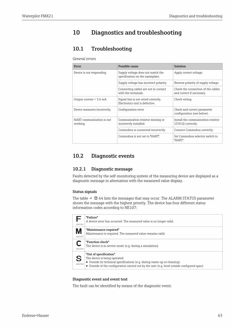
Waterpilot FMX21 Diagnostics and troubleshooting
Endress+Hauser 63
10 Diagnostics and troubleshooting
10.1 Troubleshooting
General errors
Error Possible cause Solution
Device is not responding. Supply voltage does not match thespecification on the nameplate.
Apply correct voltage.
Supply voltage has incorrect polarity. Reverse polarity of supply voltage.
Connecting cables are not in contactwith the terminals.
Check the connection of the cablesand correct if necessary.
Output current < 3.6 mA Signal line is not wired correctly.Electronics unit is defective.
Check wiring.
Device measures incorrectly. Configuration error Check and correct parameterconfiguration (see below).
HART communication is notworking.
Communication resistor missing orincorrectly installed.
Install the communication resistor(250 Ω) correctly.
Commubox is connected incorrectly. Connect Commubox correctly.
Commubox is not set to "HART". Set Commubox selector switch to"HART".
10.2 Diagnostic events
10.2.1 Diagnostic messageFaults detected by the self-monitoring system of the measuring device are displayed as adiagnostic message in alternation with the measured value display.
Status signalsThe table → 64 lists the messages that may occur. The ALARM STATUS parametershows the message with the highest priority. The device has four different statusinformation codes according to NE107:
A0013956
"Failure"A device error has occurred. The measured value is no longer valid.
A0013957
"Maintenance required"Maintenance is required. The measured value remains valid.
A0013959
"Function check"The device is in service mode (e.g. during a simulation).
A0013958
"Out of specification"The device is being operated:• Outside its technical specifications (e.g. during warm-up or cleaning).• Outside of the configuration carried out by the user (e.g. level outside configured span)
Diagnostic event and event textThe fault can be identified by means of the diagnostic event.
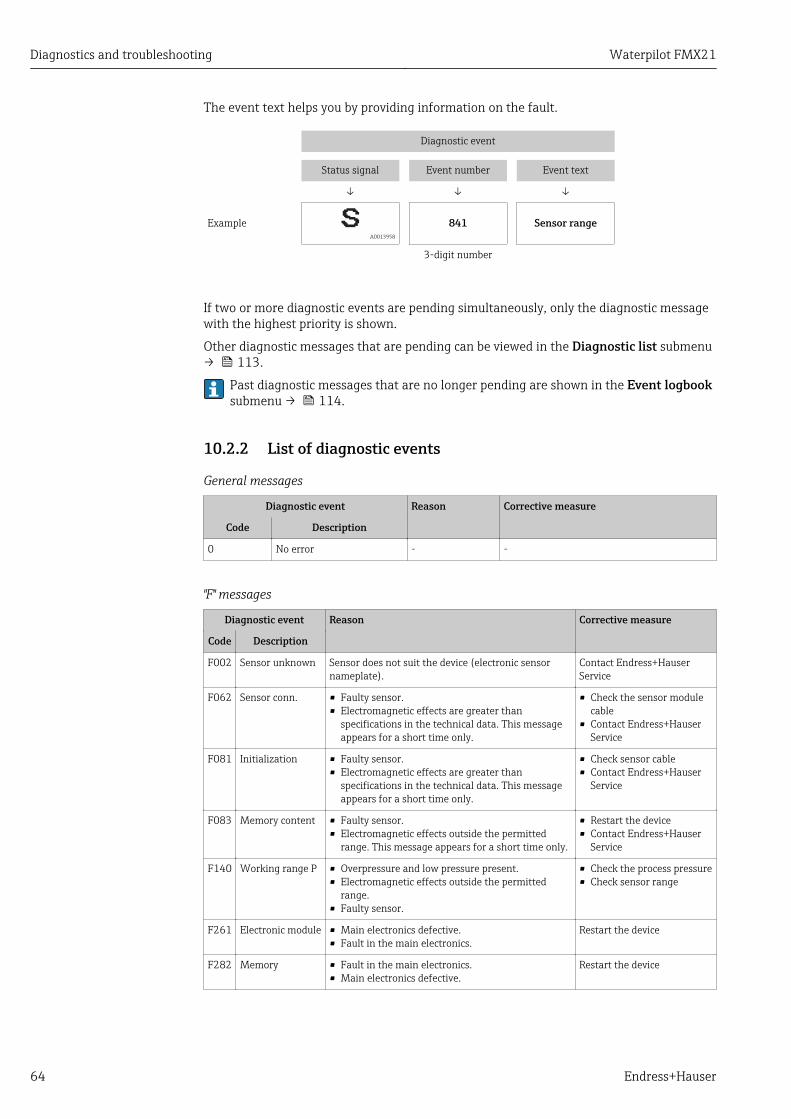
Diagnostics and troubleshooting Waterpilot FMX21
64 Endress+Hauser
The event text helps you by providing information on the fault.
Diagnostic event
Status signal Event number Event text
↓ ↓ ↓
Example A0013958
841 Sensor range
3-digit number
If two or more diagnostic events are pending simultaneously, only the diagnostic messagewith the highest priority is shown.
Other diagnostic messages that are pending can be viewed in the Diagnostic list submenu→ 113.
Past diagnostic messages that are no longer pending are shown in the Event logbooksubmenu → 114.
10.2.2 List of diagnostic events
General messages
Diagnostic event Reason Corrective measure
Code Description
0 No error - -
"F" messages
Diagnostic event Reason Corrective measure
Code Description
F002 Sensor unknown Sensor does not suit the device (electronic sensornameplate).
Contact Endress+HauserService
F062 Sensor conn. • Faulty sensor.• Electromagnetic effects are greater than
specifications in the technical data. This messageappears for a short time only.
• Check the sensor modulecable
• Contact Endress+HauserService
F081 Initialization • Faulty sensor.• Electromagnetic effects are greater than
specifications in the technical data. This messageappears for a short time only.
• Check sensor cable• Contact Endress+Hauser
Service
F083 Memory content • Faulty sensor.• Electromagnetic effects outside the permitted
range. This message appears for a short time only.
• Restart the device• Contact Endress+Hauser
Service
F140 Working range P • Overpressure and low pressure present.• Electromagnetic effects outside the permitted
range.• Faulty sensor.
• Check the process pressure• Check sensor range
F261 Electronic module • Main electronics defective.• Fault in the main electronics.
Restart the device
F282 Memory • Fault in the main electronics.• Main electronics defective.
Restart the device
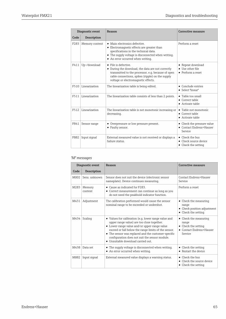
Waterpilot FMX21 Diagnostics and troubleshooting
Endress+Hauser 65
Diagnostic event Reason Corrective measure
Code Description
F283 Memory content • Main electronics defective.• Electromagnetic effects are greater than
specifications in the technical data.• The supply voltage is disconnected when writing.• An error occurred when writing.
Perform a reset
F411 Up-/download • File is defective.• During the download, the data are not correctly
transmitted to the processor, e.g. because of opencable connections, spikes (ripple) on the supplyvoltage or electromagnetic effects.
• Repeat download• Use other file• Perform a reset
F510 Linearization The linearization table is being edited. • Conclude entries• Select "linear"
F511 Linearization The linearization table consists of less than 2 points. • Table too small• Correct table• Activate table
F512 Linearization The linearization table is not monotonic increasing ordecreasing.
• Table not monotonic• Correct table• Activate table
F841 Sensor range • Overpressure or low pressure present.• Faulty sensor.
• Check the pressure value• Contact Endress+Hauser
Service
F882 Input signal External measured value is not received or displays afailure status.
• Check the bus• Check source device• Check the setting
"M" messages
Diagnostic event Reason Corrective measure
Code Description
M002 Sens. unknown Sensor does not suit the device (electronic sensornameplate). Device continues measuring.
Contact Endress+HauserService
M283 Memorycontent
• Cause as indicated for F283.• Correct measurement can continue as long as you
do not need the peakhold indicator function.
Perform a reset
M431 Adjustment The calibration performed would cause the sensornominal range to be exceeded or undershot.
• Check the measuringrange
• Check position adjustment• Check the setting
M434 Scaling • Values for calibration (e.g. lower range value andupper range value) are too close together.
• Lower-range value and/or upper-range valueexceed or fall below the range limits of the sensor.
• The sensor was replaced and the customer-specificconfiguration does not suit the sensor module.
• Unsuitable download carried out.
• Check the measuringrange
• Check the setting• Contact Endress+Hauser
Service
M438 Data set • The supply voltage is disconnected when writing.• An error occurred when writing.
• Check the setting• Restart the device
M882 Input signal External measured value displays a warning status. • Check the bus• Check the source device• Check the setting

Diagnostics and troubleshooting Waterpilot FMX21
66 Endress+Hauser
"C" messages
Diagnostic event Reason Corrective measure
Code Description
C412 Backup in prog. Downloading. Wait for download tocomplete.
C482 Simul. output Simulation of the current output is switched on, i.e. thedevice is not measuring at present.
End the simulation
C484 Error simul. Fault state simulation is switched on, i.e. the device isnot measuring at present.
End the simulation
C485 Measure simul. Simulation is switched on, i.e. the device is notmeasuring at present.
End the simulation
C824 Process pressure • Overpressure or low pressure present.• Electromagnetic effects outside the permitted range.
This message appears for a short time only.
• Check the pressure value• Restart the device• Perform a reset
"S" messages
Diagnostic event Reason Corrective measure
Code Description
S110 Operationalrange T
• High temperature or low temperature present.• Electromagnetic effects outside the permitted
range.• Faulty sensor.
• Check processtemperature
• Check the temperaturerange
S140 Working range PLP/HP
• Overpressure or low pressure present.• Electromagnetic effects outside the permitted
range.• Faulty sensor.
• Check the processpressure
• Check sensor range
S822 Process temp.LP/HP
• The temperature measured in the sensor is higherthan the upper nominal temperature of the sensor.
• The temperature measured in the sensor is lowerthan the lower nominal temperature of the sensor.
• Check temperature• Check the setting
S841 Sensor range • Overpressure or low pressure present.• Faulty sensor.
• Check the pressure value• Contact Endress+Hauser
Service
S971 Adjustment • The current is outside the permitted range from 3.8to 20.5 mA.
• The present pressure value is outside the configuredmeasuring range (but within the sensor modulerange, if applicable).
• The calibration performed would cause the sensornominal range to be exceeded or undershot.
• Check the pressure value• Check the measuring
range• Check the setting
10.3 Troubleshooting specific to Waterpilot FMX21 withoptional Pt100
Error description Reason Corrective action
No measuring signal 4 to 20 mA cable not connectedcorrectly
Connect device as per → 25.
No power supplied via the 4 to 20 mAcable
Check current loop.
Supply voltage too low (min. 10.5 VDC)
• Check supply voltage.• Overall resistance greater than
max. load resistance
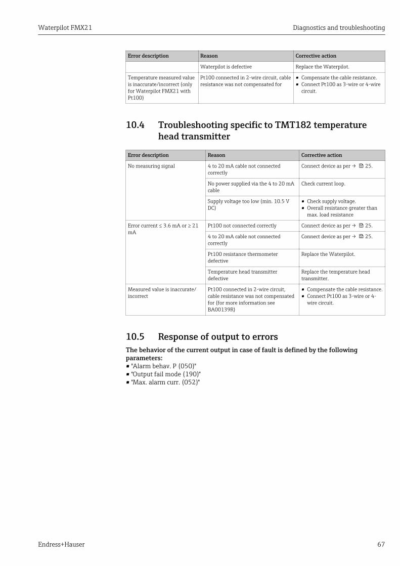
Waterpilot FMX21 Diagnostics and troubleshooting
Endress+Hauser 67
Error description Reason Corrective action
Waterpilot is defective Replace the Waterpilot.
Temperature measured valueis inaccurate/incorrect (onlyfor Waterpilot FMX21 withPt100)
Pt100 connected in 2-wire circuit, cableresistance was not compensated for
• Compensate the cable resistance.• Connect Pt100 as 3-wire or 4-wire
circuit.
10.4 Troubleshooting specific to TMT182 temperaturehead transmitter
Error description Reason Corrective action
No measuring signal 4 to 20 mA cable not connectedcorrectly
Connect device as per → 25.
No power supplied via the 4 to 20 mAcable
Check current loop.
Supply voltage too low (min. 10.5 VDC)
• Check supply voltage.• Overall resistance greater than
max. load resistance
Error current ≤ 3.6 mA or ≥ 21mA
Pt100 not connected correctly Connect device as per → 25.
4 to 20 mA cable not connectedcorrectly
Connect device as per → 25.
Pt100 resistance thermometerdefective
Replace the Waterpilot.
Temperature head transmitterdefective
Replace the temperature headtransmitter.
Measured value is inaccurate/incorrect
Pt100 connected in 2-wire circuit,cable resistance was not compensatedfor (for more information seeBA00139R)
• Compensate the cable resistance.• Connect Pt100 as 3-wire or 4-
wire circuit.
10.5 Response of output to errorsThe behavior of the current output in case of fault is defined by the followingparameters:• "Alarm behav. P (050)"• "Output fail mode (190)"• "Max. alarm curr. (052)"
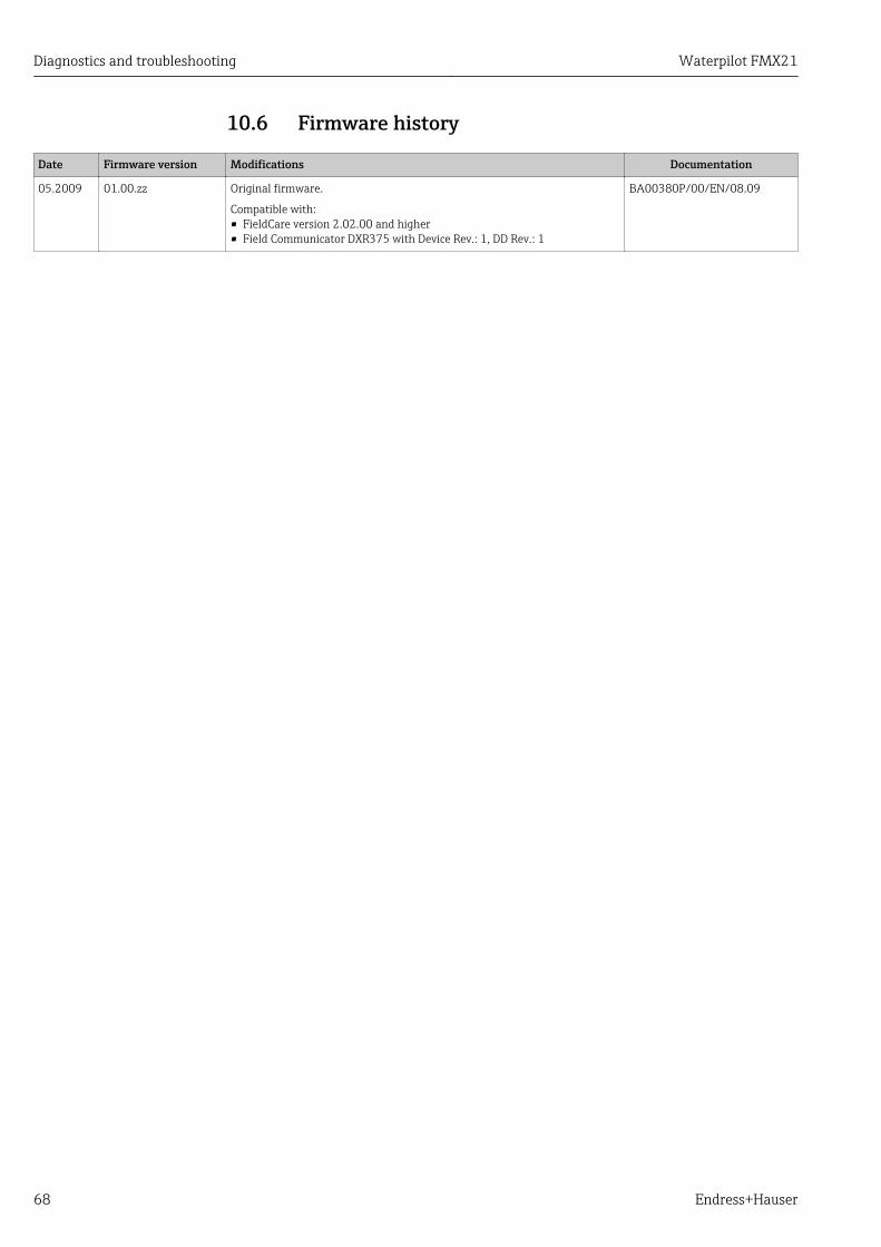
Diagnostics and troubleshooting Waterpilot FMX21
68 Endress+Hauser
10.6 Firmware history
Date Firmware version Modifications Documentation
05.2009 01.00.zz Original firmware.
Compatible with:• FieldCare version 2.02.00 and higher• Field Communicator DXR375 with Device Rev.: 1, DD Rev.: 1
BA00380P/00/EN/08.09
Waterpilot FMX21 Maintenance
Endress+Hauser 69
11 Maintenance• Terminal box: Keep the GORE-TEX® filter free from contamination• FMX21 extension cable: Keep the Teflon filter in the pressure compensation tube free
from contamination• Check the process isolating diaphragm for buildup at suitable intervals.
11.1 Exterior cleaningPlease note the following points when cleaning the device:• The cleaning agents used should not corrode the surface and the seals.• Mechanical damage to the process isolating diaphragm, e.g. due to sharp objects, must
be avoided.• Only clean the terminal box with water or with a cloth dampened with very diluted
ethanol.
Repairs Waterpilot FMX21
70 Endress+Hauser
12 Repairs
12.1 General notes
12.1.1 Repair conceptRepairs are not possible.
12.1.2 Replacing a deviceOnce a complete device has been replaced, the parameters can be transferred back into thedevice using FieldCare:
Prerequisite: The configuration of the old device was saved previously to the computerusing FieldCare.
You can continue to measure without performing a new calibration.
12.2 Spare partsAll the spare parts for the measuring device along with the order code are listed In theW@M Device Viewer (www.endress.com/deviceviewer) and can be ordered. If available,users can also download the associated Installation Instructions.
Measuring device serial number:• Is located on the nameplate of the device.• Can be read out via the "Serial number" parameter in the "Instrument info" submenu.
12.3 ReturnThe measuring device must be returned in the event of a factory calibration, or if thewrong device has been ordered or delivered.
As an ISO-certified company and also due to legal regulations, Endress+Hauser is obligedto follow certain procedures when handling any returned products that have been incontact with medium. To ensure swift, safe and professional device returns, please readthe return procedures and conditions on the Endress+Hauser website atwww.services.endress.com/return-material
‣ Select country. The web site of the responsible sales office opens with all of the relevant
information relating to returns.
1. If the desired country is not listed:Click on the "Choose your location" link. An overview of Endress+Hauser sales offices and representatives opens.
2. Contact your Endress+Hauser sales office or representative.
12.4 DisposalWhen disposing, separate and recycle the device components based on the materials.
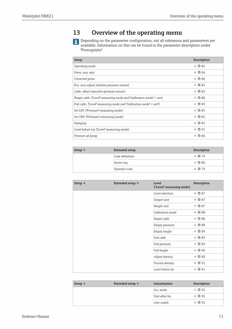
Waterpilot FMX21 Overview of the operating menu
Endress+Hauser 71
13 Overview of the operating menuDepending on the parameter configuration, not all submenus and parameters areavailable. Information on this can be found in the parameter description under"Prerequisite".
Setup Description
Operating mode → 82
Press. eng. unit → 84
Corrected press. → 86
Pos. zero adjust (relative pressure sensor) → 83
Calib. offset (absolute pressure sensor) → 83
Empty calib. ("Level" measuring mode and "Calibration mode" = wet) → 88
Full calib. ("Level" measuring mode and "Calibration mode" = wet") → 89
Set LRV ("Pressure" measuring mode) → 85
Set URV ("Pressure" measuring mode) → 85
Damping → 83
Level before Lin ("Level" measuring mode) → 91
Pressure af.damp → 86
Setup → Extended setup Description
Code definition → 79
Device tag → 80
Operator code → 79
Setup → Extended setup → Level("Level" measuring mode)
Description
Level selection → 87
Output unit → 87
Height unit → 87
Calibration mode → 88
Empty calib. → 88
Empty pressure → 88
Empty height → 89
Full calib. → 89
Full pressure → 89
Full height → 90
Adjust density → 90
Process density → 91
Level before lin → 91
Setup → Extended setup → Linearization Description
Lin. mode → 92
Unit after lin. → 92
Line-numb: → 92
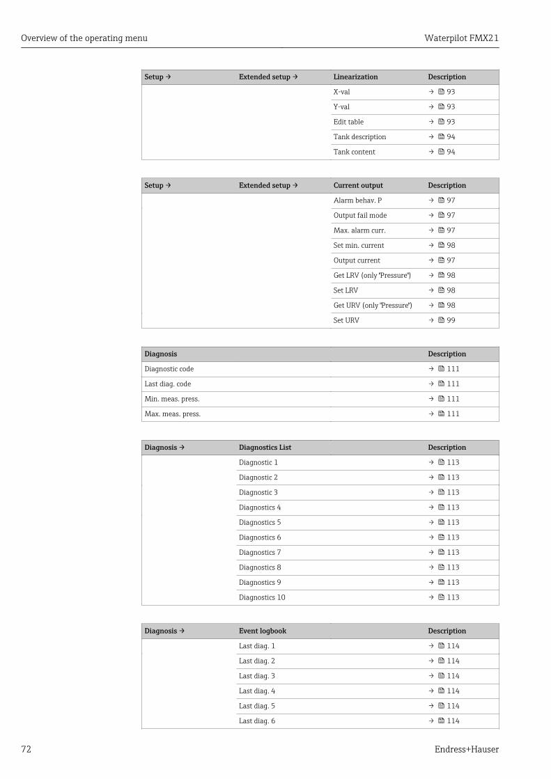
Overview of the operating menu Waterpilot FMX21
72 Endress+Hauser
Setup → Extended setup → Linearization Description
X-val → 93
Y-val → 93
Edit table → 93
Tank description → 94
Tank content → 94
Setup → Extended setup → Current output Description
Alarm behav. P → 97
Output fail mode → 97
Max. alarm curr. → 97
Set min. current → 98
Output current → 97
Get LRV (only "Pressure") → 98
Set LRV → 98
Get URV (only "Pressure") → 98
Set URV → 99
Diagnosis Description
Diagnostic code → 111
Last diag. code → 111
Min. meas. press. → 111
Max. meas. press. → 111
Diagnosis → Diagnostics List Description
Diagnostic 1 → 113
Diagnostic 2 → 113
Diagnostic 3 → 113
Diagnostics 4 → 113
Diagnostics 5 → 113
Diagnostics 6 → 113
Diagnostics 7 → 113
Diagnostics 8 → 113
Diagnostics 9 → 113
Diagnostics 10 → 113
Diagnosis → Event logbook Description
Last diag. 1 → 114
Last diag. 2 → 114
Last diag. 3 → 114
Last diag. 4 → 114
Last diag. 5 → 114
Last diag. 6 → 114
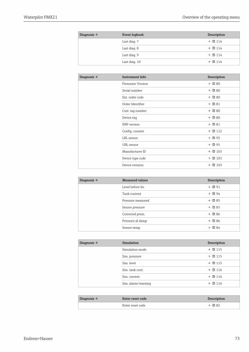
Waterpilot FMX21 Overview of the operating menu
Endress+Hauser 73
Diagnosis → Event logbook Description
Last diag. 7 → 114
Last diag. 8 → 114
Last diag. 9 → 114
Last diag. 10 → 114
Diagnosis → Instrument Info Description
Firmware Version → 80
Serial number → 80
Ext. order code → 80
Order Identifier → 81
Cust. tag number → 80
Device tag → 80
ENP version → 81
Config. counter → 112
LRL sensor → 95
URL sensor → 95
Manufacturer ID → 103
Device type code → 103
Device revision → 103
Diagnosis → Measured values Description
Level before lin → 91
Tank content → 94
Pressure measured → 85
Sensor pressure → 85
Corrected press. → 86
Pressure af.damp → 86
Sensor temp. → 84
Diagnosis → Simulation Description
Simulation mode → 115
Sim. pressure → 115
Sim. level → 115
Sim. tank cont. → 116
Sim. current → 116
Sim. alarm/warning → 116
Diagnosis → Enter reset code Description
Enter reset code → 82
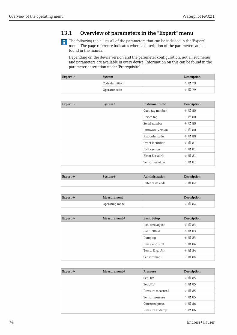
Overview of the operating menu Waterpilot FMX21
74 Endress+Hauser
13.1 Overview of parameters in the "Expert" menuThe following table lists all of the parameters that can be included in the "Expert"menu. The page reference indicates where a description of the parameter can befound in the manual.
Depending on the device version and the parameter configuration, not all submenusand parameters are available in every device. Information on this can be found in theparameter description under "Prerequisite".
Expert → System Description
Code definition → 79
Operator code → 79
Expert → System→ Instrument Info Description
Cust. tag number → 80
Device tag → 80
Serial number → 80
Firmware Version → 80
Ext. order code → 80
Order Identifier → 81
ENP version → 81
Electr.Serial No → 81
Sensor serial no. → 81
Expert → System→ Administration Description
Enter reset code → 82
Expert → Measurement Description
Operating mode → 82
Expert → Measurement→ Basic Setup Description
Pos. zero adjust → 83
Calib. Offset → 83
Damping → 83
Press. eng. unit → 84
Temp. Eng. Unit → 84
Sensor temp. → 84
Expert → Measurement→ Pressure Description
Set LRV → 85
Set URV → 85
Pressure measured → 85
Sensor pressure → 85
Corrected press. → 86
Pressure af.damp → 86
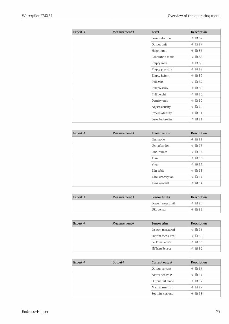
Waterpilot FMX21 Overview of the operating menu
Endress+Hauser 75
Expert → Measurement→ Level Description
Level selection → 87
Output unit → 87
Height unit → 87
Calibration mode → 88
Empty calib. → 88
Empty pressure → 88
Empty height → 89
Full calib. → 89
Full pressure → 89
Full height → 90
Density unit → 90
Adjust density → 90
Process density → 91
Level before lin. → 91
Expert → Measurement→ Linearization Description
Lin. mode → 92
Unit after lin. → 92
Line-numb: → 92
X-val → 93
Y-val → 93
Edit table → 93
Tank description → 94
Tank content → 94
Expert → Measurement→ Sensor limits Description
Lower range limit → 95
URL sensor → 95
Expert → Measurement→ Sensor trim Description
Lo trim measured → 96
Hi trim measured → 96
Lo Trim Sensor → 96
Hi Trim Sensor → 96
Expert → Output→ Current output Description
Output current → 97
Alarm behav. P → 97
Output fail mode → 97
Max. alarm curr. → 97
Set min. current → 98
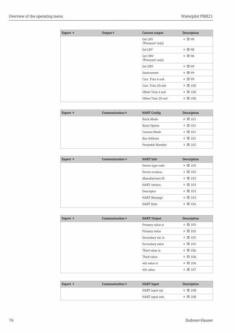
Overview of the operating menu Waterpilot FMX21
76 Endress+Hauser
Expert → Output→ Current output Description
Get LRV("Pressure" only)
→ 98
Set LRV → 98
Get URV("Pressure" only)
→ 98
Set URV → 99
Startcurrent → 99
Curr. Trim 4 mA → 99
Curr. Trim 20 mA → 100
Offset Trim 4 mA → 100
Offset Trim 20 mA → 100
Expert → Communication→ HART Config Description
Burst Mode → 101
Burst Option → 101
Current Mode → 101
Bus Address → 101
Preamble Number → 102
Expert → Communication→ HART Info Description
Device type code → 103
Device revision → 103
Manufacturer ID → 103
HART version → 103
Descriptor → 103
HART Message → 103
HART Date → 104
Expert → Communication→ HART Output Description
Primary value is → 105
Primary value → 105
Secondary val. is → 105
Secondary value → 105
Third value is → 106
Third value → 106
4th value is → 106
4th value → 107
Expert → Communication→ HART Input Description
HART input val. → 108
HART input stat. → 108

Waterpilot FMX21 Overview of the operating menu
Endress+Hauser 77
Expert → Communication→ HART Input Description
HART input unit → 108
HART input form. → 108
Expert → Application Description
Electr. Delta P → 110
Fixed ext. value → 110
Auto dens. corr. → 110
Expert → Diagnosis Description
Diagnostic code → 111
Last diag. code → 111
Reset Logbook → 111
Min. meas. press. → 111
Max. meas. press. → 111
Reset Peakhold → 112
Operating hours → 112
Config. counter → 112
Expert → Diagnosis→ Diagnostics List Description
Diagnostic 1 → 113
Diagnostic 2 → 113
Diagnostic 3 → 113
Diagnostics 4 → 113
Diagnostics 5 → 113
Diagnostics 6 → 113
Diagnostics 7 → 113
Diagnostics 8 → 113
Diagnostics 9 → 113
Diagnostics 10 → 113
Expert → Diagnosis→ Event logbook Description
Last diag. 1 → 114
Last diag. 2 → 114
Last diag. 3 → 114
Last diag. 4 → 114
Last diag. 5 → 114
Last diag. 6 → 114
Last diag. 7 → 114
Last diag. 8 → 114
Last diag. 9 → 114
Last diag. 10 → 114

Overview of the operating menu Waterpilot FMX21
78 Endress+Hauser
Expert → Diagnosis→ Simulation Description
Simulation mode → 115
Sim. pressure → 115
Sim. level → 115
Sim. tank cont. → 116
Sim. current → 116
Sim. alarm/warning → 116
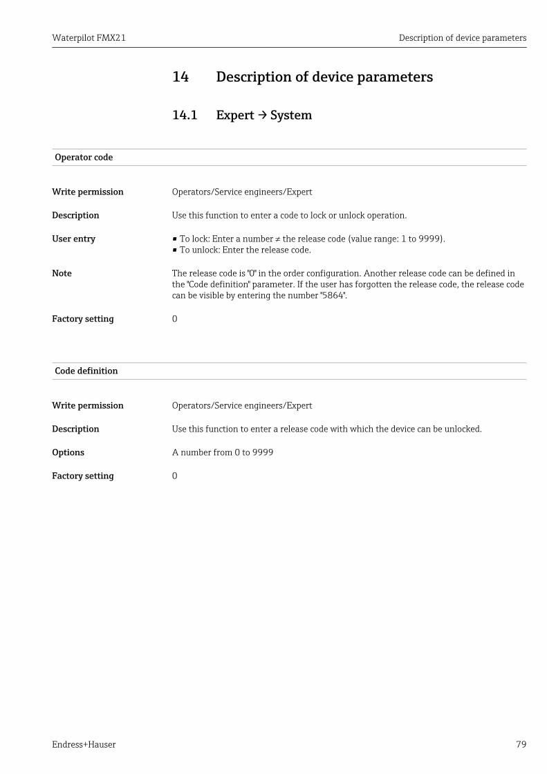
Waterpilot FMX21 Description of device parameters
Endress+Hauser 79
14 Description of device parameters
14.1 Expert → System
Operator code
Write permission Operators/Service engineers/Expert
Description Use this function to enter a code to lock or unlock operation.
User entry • To lock: Enter a number ¹ the release code (value range: 1 to 9999).• To unlock: Enter the release code.
Note The release code is "0" in the order configuration. Another release code can be defined inthe "Code definition" parameter. If the user has forgotten the release code, the release codecan be visible by entering the number "5864".
Factory setting 0
Code definition
Write permission Operators/Service engineers/Expert
Description Use this function to enter a release code with which the device can be unlocked.
Options A number from 0 to 9999
Factory setting 0
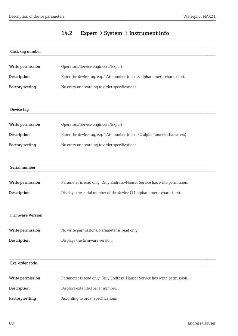
Description of device parameters Waterpilot FMX21
80 Endress+Hauser
14.2 Expert → System → Instrument info
Cust. tag number
Write permission Operators/Service engineers/Expert
Description Enter the device tag, e.g. TAG number (max. 8 alphanumeric characters).
Factory setting No entry or according to order specifications
Device tag
Write permission Operators/Service engineers/Expert
Description Enter the device tag, e.g. TAG number (max. 32 alphanumeric characters).
Factory setting No entry or according to order specifications
Serial number
Write permission Parameter is read only. Only Endress+Hauser Service has write permission.
Description Displays the serial number of the device (11 alphanumeric characters).
Firmware Version
Write permission No write permissions. Parameter is read only.
Description Displays the firmware version.
Ext. order code
Write permission Parameter is read only. Only Endress+Hauser Service has write permission.
Description Displays extended order number.
Factory setting According to order specifications

Waterpilot FMX21 Description of device parameters
Endress+Hauser 81
Order identifier
Write permission Parameter is read only. Only Endress+Hauser Service has write permission.
Description Displays the order identifier.
Factory setting According to order specifications
ENP version
Write permission No write permissions. Parameter is read only.
Description Displays the ENP version(ENP = electronic nameplate)
Electr.serial no.
Write permission No write permissions. Parameter is read only.
Description Displays the serial number of the main electronics (11 alphanumeric characters).
Sensor serial no.
Write permission No write permissions. Parameter is read only.
Description Displays the serial number of the main electronics (11 alphanumeric characters).
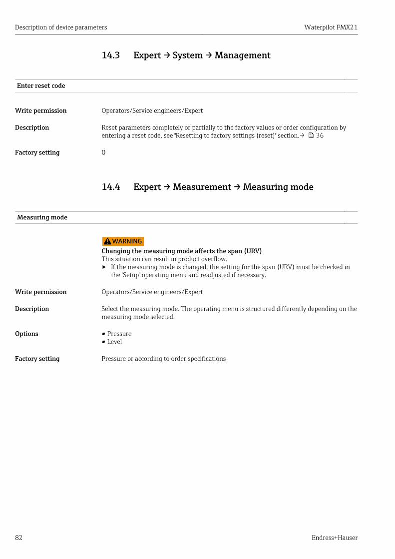
Description of device parameters Waterpilot FMX21
82 Endress+Hauser
14.3 Expert → System → Management
Enter reset code
Write permission Operators/Service engineers/Expert
Description Reset parameters completely or partially to the factory values or order configuration byentering a reset code, see "Resetting to factory settings (reset)" section.→ 36
Factory setting 0
14.4 Expert → Measurement → Measuring mode
Measuring mode
LWARNINGChanging the measuring mode affects the span (URV)This situation can result in product overflow.‣ If the measuring mode is changed, the setting for the span (URV) must be checked in
the "Setup" operating menu and readjusted if necessary.
Write permission Operators/Service engineers/Expert
Description Select the measuring mode. The operating menu is structured differently depending on themeasuring mode selected.
Options • Pressure• Level
Factory setting Pressure or according to order specifications

Waterpilot FMX21 Description of device parameters
Endress+Hauser 83
14.5 Expert → Measurement → Basic setup
Pos. zero adjust
Write permission Operators/Service engineers/Expert
Description Position adjustment – the pressure difference between zero (set point) and the measuredpressure need not be known.
Example • Measured value = 2.2 mbar (0.033 psi)• You correct the measured value via the "Pos. zero adjust" parameter with the "Confirm"
option. This means that you are assigning the value 0.0 to the pressure present.• Measured value (after position adjustment) = 0.0 mbar• The current value is also corrected.
Options • Confirm• Cancel
Factory setting Cancel
Calib. offset
Write permission Service engineers/Expert
Description Position adjustment – the pressure difference between the set point and the measuredpressure must be known.
Example • Measured value = 982.2 mbar (14.73 psi)• You correct the measured value with the value entered (e.g. 2.2 mbar (0.033 psi)) via
the "Calib. Offset" parameter. This means that you are assigning the value 980.0 (14.7psi) to the pressure present.
• Measured value (after pos. zero adjust) = 980.0 mbar (14.7 psi)• The current value is also corrected.
Factory setting 0.0
Damping
Write permission Operators/Service engineers/Expert(if the "Damping" DIP switch is set to "on")
Description Enter damping time (time constant t).The damping affects the speed at which the measured value reacts to changes in pressure.
Input range 0.0 to 999.0 s
Factory setting 2.0 sec. or according to order specifications
Description of device parameters Waterpilot FMX21
84 Endress+Hauser
Press. eng. unit
Write permission Operators/Service engineers/Expert
Description Select the pressure engineering unit. If a new pressure engineering unit is selected, allpressure-specific parameters are converted and displayed with the new unit.
Options • mbar, bar• mmH2O, mH2O, inH2O• ftH2O• Pa, kPa, MPa• psi• mmHg, inHg• kgf/cm2
Factory setting mbar or bar depending on the nominal measuring range of the sensor module, or as perorder specifications
Temp. eng. unit
Write permission Service engineers/Expert
Description Select the unit for the temperature measured values.
Options • °C• °F• K
Note The setting affects the unit for the "Sensor temp." parameter.
Factory setting °C
Sensor temp.
Write permission No write permissions. Parameter is read only.
Description Displays the temperature currently measured in the sensor module. This can deviate fromthe process temperature.
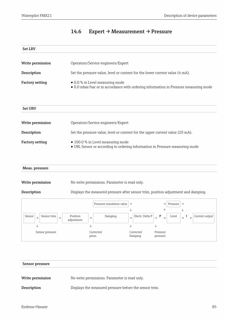
Waterpilot FMX21 Description of device parameters
Endress+Hauser 85
14.6 Expert → Measurement → Pressure
Set LRV
Write permission Operators/Service engineers/Expert
Description Set the pressure value, level or content for the lower current value (4 mA).
Factory setting • 0.0 % in Level measuring mode• 0.0 mbar/bar or in accordance with ordering information in Pressure measuring mode
Set URV
Write permission Operators/Service engineers/Expert
Description Set the pressure value, level or content for the upper current value (20 mA).
Factory setting • 100.0 % in Level measuring mode• URL Sensor or according to ordering information in Pressure measuring mode
Meas. pressure
Write permission No write permissions. Parameter is read only.
Description Displays the measured pressure after sensor trim, position adjustment and damping.
Pressure simulation value → → Pressure →
↓ ↑ ↓
Sensor → Sensor trim → Positionadjustment → Damping → Electr. Delta P → P → Level → I → Current output
↓ ↓ ↓ ↓
Sensor pressure Correctedpress.
CorrectedDamping
Pressurepressure
Sensor pressure
Write permission No write permissions. Parameter is read only.
Description Displays the measured pressure before the sensor trim.
Description of device parameters Waterpilot FMX21
86 Endress+Hauser
Corrected press.
Write permission No write permissions. Parameter is read only.
Description Displays the measured pressure after sensor trim and position adjustment.
Pressure af.damp
Write permission No write permissions. Parameter is read only.
Description Displays the measured pressure after sensor trim, position adjustment and damping.
Waterpilot FMX21 Description of device parameters
Endress+Hauser 87
14.7 Expert → Measurement → Level
Level selection
Write permission Operators/Service engineers/Expert
Description Select the method for calculating the level
Options • In pressureIf this option is selected, specify two pressure/level value pairs. The level value isdisplayed directly in the unit that you select via the "Output unit" parameter.
• In heightIf this option is selected, specify two height/level value pairs. From the measuredpressure, the device first calculates the height using the density. This information is thenused to calculate the level in the "Output unit" selected using the two value pairsspecified.
Factory setting In pressure
Output unit
Description Select the unit for the measured value display for the level before linearization.
Note The selected unit is used only to describe the measured value i.e. when a new output unitis selected, the measured value is not converted.
Example • Current measured value: 0.3 ft• New output unit: m• New measured value: 0.3 m
Options • %• mm, cm, dm, m• ft, inch• m3, in3
• l, hl• ft3
• gal, Igal• kg, t• lb
Factory setting %
Height unit
Write permission Operators/Service engineers/Expert
Description of device parameters Waterpilot FMX21
88 Endress+Hauser
Description Select the height unit. The measured pressure is converted to the selected height unitusing the "Adjust Density" parameter.
Prerequisite "Level selection" = "In height"
Options • mm• m• in• ft
Factory setting m
Calibration mode
Write permission Operators/Service engineers/Expert
Description Select the calibration mode.
Options • WetWet calibration takes place by filling and emptying the vessel. In the case of twodifferent levels, the level, volume, mass or percentage value entered is assigned to thepressure measured at this point in time ("Empty calib." and "Full calib." parameters).
• DryDry calibration is a theoretical calibration. For this calibration, you specify two pressure-level value pairs or height-level value pairs via the following parameters: "Empty calib.","Empty pressure", "Empty height", "Full calib.", "Full pressure", "Full height".
Factory setting Wet
Empty calib.
Write permission Operators/Service engineers/Expert
Description Enter the output value for the lower calibration point (vessel is empty). The unit defined in"Output unit" must be used.
Note • In the case of wet calibration, the level (e.g. vessel empty or partially filled) must actuallybe available. The associated pressure is then automatically recorded by the device.
• In the case of dry calibration, the level (vessel empty) does not have to be available. Forthe "In pressure" level selection, the associated pressure must be entered in the "Emptypressure" parameter. The associated height must be entered in the "Empty height"parameter for the "In height" level selection.
Factory setting 0.0
Empty pressure

Waterpilot FMX21 Description of device parameters
Endress+Hauser 89
Write permission Operators/Service engineers/Expert
Description Enter the pressure value for the lower calibration point (vessel empty). See also "Emptycalib.".
Prerequisite • "Level selection" = In pressure• "Calibration mode" = Dry -> entry• "Calibration mode" = Wet -> display
Factory setting 0.0
Empty height
Write permission Operators/Service engineers/Expert
Description Enter the height value for the lower calibration point (vessel empty). The unit is selectedvia the "Height unit" parameter.
Prerequisite • "Level selection" = "In height"• "Calibration mode" = Dry -> entry• "Calibration mode" = Wet -> display
Factory setting 0.0
Full calib.
Write permission Operators/Service engineers/Expert
Description Enter the output value for the upper calibration point (vessel full). The unit defined in"Output unit" must be used.
Note • In the case of wet calibration, the level (e.g. vessel full or partially filled) must actually beavailable. The associated pressure is then automatically recorded by the device.
• In the case of dry calibration, the level (vessel full) does not have to be available. For the"In pressure" level selection, the associated pressure must be entered in the "Full pressure"parameter. The associated height has to be entered in the "Full height" parameter for the"In height" level selection.
Factory setting 100.0
Full pressure
Write permission Operators/Service engineers/Expert
Description Enter the pressure value for the upper calibration point (vessel full). See also "Full calib.".

Description of device parameters Waterpilot FMX21
90 Endress+Hauser
Prerequisite • "Level selection" = In pressure• "Calibration mode" = Dry -> entry• "Calibration mode" = Wet -> display
Factory setting URL of the sensor module
Full height
Write permission Operators/Service engineers/Expert
Description Enter the height value for the upper calibration point (vessel full). The unit is selected viathe "Height unit" parameter.
Prerequisite • "Level selection" = "In height"• "Calibration mode" = Dry -> entry• "Calibration mode" = Wet -> display
Factory setting URL is converted to a level unit
Density unit
Write permission Service engineers/Expert
Description Displays the density unit. The measured pressure is converted to a height using the "Heightunit", "Adjust density" and "Process density" parameters.
Options • g/cm3
• kg/m3
• kg/dm3
• lb/in3
• lb/ft3
Factory setting g/cm3
Adjust density
Write permission Operators/Service engineers/Expert
Description Enter the density of the medium used to perform the calibration. The measured pressure isconverted to a height using the "Height unit" and "Adjust density" parameters.Input: Auto dens. corr. = OffDisplay: Auto dens. corr. ≠ Off
Factory setting 1.0

Waterpilot FMX21 Description of device parameters
Endress+Hauser 91
Process density
Write permission Operators/Service engineers/Expert
Description Enter a new density value for density correction. The calibration was carried out with themedium water, for example. Now the vessel is to be used for another medium withanother density. The calibration is corrected appropriately by entering the new densityvalue in the "Process Density" parameter.Input: Auto dens. corr. = OffDisplay: Auto dens. corr. ≠ Off
Note If, after completing a wet calibration, you change to dry calibration using the "Calibrationmode" parameter, the density for the "Adjust density" and "Process density" parametersmust be entered correctly before changing the calibration mode.
Factory setting 1.0
Level before lin.
Write permission No write permissions. Parameter is read only.
Description Displays the level value prior to linearization.

Description of device parameters Waterpilot FMX21
92 Endress+Hauser
14.8 Expert → Measurement → Linearization
Lin. mode
Write permission Operators/Service engineers/Expert
Description Select the linearization mode.
Options • LinearThe level is output without being converted beforehand. "Level before lin" is output.
• Erase tableThe existing linearization table is deleted.
• Manual entry (sets the table to edit mode, an alarm is output):The value pairs of the table (X-value and Y-value) are entered manually.
• Semi-automatic entry (sets the table to edit mode, an alarm is output):The vessel is emptied or filled in stages in this entry mode. The device automaticallyrecords the level value (X-value). The associated volume, mass or % value is enteredmanually (Y-value).
• Activate tableThe table entered is activated and checked with this option. The device shows the levelafter linearization.
Factory setting Linear
Unit after lin.
Write permission Operators/Service engineers/Expert
Description Select volume unit, mass, height or % (unit of the Y-value).
Options • %• cm, dm, m, mm• hl• in3, ft3, m3,• l• in, ft• kg, t• lb• gal• Igal
Factory setting %
Line-numb
Write permission Operators/Service engineers/Expert
Waterpilot FMX21 Description of device parameters
Endress+Hauser 93
Description Enter the number of the current point in the table. Subsequent entries in "X-val" and "Y-val"relate to this point.
Input range 1...32
X-val
Write permission Operators/Service engineers/Expert
Description Enter the X-value (level before linearization) for the specific point in the table and confirm.
Note • If "Lin. mode" = "Manual", the level value must be entered.• If "Lin. mode" = "Semiautomatic", the level value is displayed and must be confirmed by
entering the paired Y-value.
Y-value
Write permission Operators/Service engineers/Expert
Description Enter the Y-value (value after linearization) for the specific point in the table. The unit isdetermined by "Unit after lin.".
Note The linearization table must be monotonic (increasing or decreasing).
Edit table
Write permission Operators/Service engineers/Expert
Description Select the function for entering the table.
Options • Next point: Enter the next point.• Current point: stay on the current point to correct a mistake for example.• Last input point: skip back to previous point to correct a mistake for example.• Insert point: Insert an additional point (see example below).• Delete point: Delete the current point (see example below).
Example Add point, in this case between the 4th and 5th point for example• Select point 5 via the "Line-numb" parameter.• Select the "Insert point" option via the "Edit table" parameter.• Point 5 is displayed for the "Line-numb" parameter. Enter new values for the "X-val" and
"Y-val" parameters.
Delete point, in this case the 5th point for example• Select point 5 via the "Line-numb" parameter.• Select the "Delete point" option via the "Edit table" parameter.• The 5th point is deleted. All of the following points are pushed up one number i.e.
following deletion, the 6th point becomes Point 5.
Description of device parameters Waterpilot FMX21
94 Endress+Hauser
Factory setting Current point
Tank description
Write permission Operators/Service engineers/Expert
Description Enter the tank description (max. 32 alphanumeric characters)
Tank content
Write permission No write permissions. Parameter is read only.
Description Displays the level value after linearization.
Waterpilot FMX21 Description of device parameters
Endress+Hauser 95
14.9 Expert → Measurement → Sensor limits
LRL sensor
Write permission No write permissions. Parameter is read only.
Description Displays the lower-range limit of the sensor.
URL sensor
Write permission No write permissions. Parameter is read only.
Description Displays the upper-range limit of the sensor.

Description of device parameters Waterpilot FMX21
96 Endress+Hauser
14.10 Expert → Measurement → Sensor trim
Lo trim measured
Write permission Parameter is read only. Only Endress+Hauser Service has write permission.
Description Displays the reference pressure present to be accepted for the lower calibration point.
Hi trim measured
Write permission Parameter is read only. Only Endress+Hauser Service has write permission.
Description Displays the reference pressure present to be accepted for the upper calibration point.
Lo trim sensor
Write permission No write permissions. Parameter is read only.
Description Sensor module recalibration by entering a target pressure while simultaneously andautomatically accepting a reference pressure present for the lower calibration point.
Hi trim sensor
Write permission No write permissions. Parameter is read only.
Description Sensor module recalibration by entering a target pressure while simultaneously andautomatically accepting a reference pressure present for the upper calibration point.
Waterpilot FMX21 Description of device parameters
Endress+Hauser 97
14.11 Expert → Output → Current output
Output current
Write permission Operators/Service engineers/Expert
Description Displays the current current value.
Alarm behav. P
Write permission Operators/Service engineers/Expert
Description Configure the response of the current output if sensor module limits are overshot orundershot.
Options • WarningThe device continues to measure. An error message is displayed.
• AlarmThe output signal assumes a value that can be specified by the "Output fail mode"function.
Factory setting Warning
Output fail mode
Write permission Operators/Service engineers/Expert
Description Select Output fail mode. In the event of an alarm, the current assumes the current valuespecified with this parameter.
Options • Max: can be set from 21 to 23 mA, see also "High alarm curr."• Hold: last measured value is held.• Min: 3.6 mA
Factory setting Max (22 mA)
Max. alarm curr.
Write permission Operators/Service engineers/Expert
Description Enter the current value for maximum alarm current. See also "Output fail mode".
Input range 21 to 23 mA
Description of device parameters Waterpilot FMX21
98 Endress+Hauser
Factory setting 22 mA
Set min. current
Write permission Operators/Service engineers/Expert
Description Enter lower current limit.Some switching units accept no current smaller than 4.0 mA.
Options • 3.8 mA• 4.0 mA
Factory setting 3.8 mA
Get LRV
Write permission Operators/Service engineers/Expert
Description Set the lower-range value – reference pressure is present at the device. The pressure forthe lower current value (4 mA) is present at the device. Use the "Confirm" option to assignthe lower current value to the applied pressure value.
Prerequisite: Pressure measuring mode
Options • Cancel• Confirm
Factory setting Cancel
Set LRV
Write permission Operators/Service engineers/Expert
Description Set the pressure value, level or content for the lower current value (4 mA).
Factory setting • 0.0 % in Level measuring mode• 0.0 mbar/bar or in accordance with ordering information in Pressure measuring mode
Get URV (pressure measuring mode)
Write permission Operators/Service engineers/Expert
Waterpilot FMX21 Description of device parameters
Endress+Hauser 99
Description Set the upper-range value – reference pressure is present at the device. The pressure forthe upper current value (20 mA) is present at the device. Use the "Confirm" option to assignthe applied pressure value to the upper current value.
Prerequisite: Pressure measuring mode
Options • Cancel• Confirm
Factory setting Cancel
Set URV
Write permission Operators/Service engineers/Expert
Description Set the pressure value, level or content for the upper current value (20 mA).
Factory setting • 100.0 % in Level measuring mode• URL Sensor or according to ordering information in Pressure measuring mode
Startcurrent
Write permission Service engineers/Expert
Description Entry of the start current. This setting also applies in the HART Multidrop mode.
Options • 12 mA• Max alarm (22 mA, cannot be set)
Factory setting 12 mA
Curr. trim 4mA
Write permission Service engineers/Expert
Description Enter the pressure value for the lower point (4 mA) of the current partial regression lines.Using this parameter and "Curr. trim 20 mA", you can adapt the current output to thetransmission conditions.
Options Carry out the current trim for the lower point as follows.• Select the "Current" option in the "Simulation mode" parameter.• In the "Sim current" parameter, configure the "4 mA value".• Enter the current value measured using the switching unit in the "Curr. trim 4mA"
parameter.
Input range Measured current ±0.2 mA
Description of device parameters Waterpilot FMX21
100 Endress+Hauser
Factory setting 4 mA
Curr. trim 20mA
Write permission Service engineers/Expert
Description Enter the pressure value for the upper point (20 mA) of the current partial regressionlines. Using this parameter and "Curr. Trim 4 mA", you can adapt the current output to thetransmission conditions.
Options Carry out the current trim for the upper point as follows:• Select the "Current" option in the "Simulation mode" parameter.• In the "Sim current" parameter, configure the value "20 mA".• Enter the current value measured using the switching unit in the "Curr. trim 20mA"
parameter.
Input range Measured current ±1 mA
Factory setting 20 mA
Offset trim 4mA
Write permission Service engineers/Expert
Description Display/enter the difference between 4 mA and the value entered for the parameter "Curr.trim 4mA".
Factory setting 0
Offset trim 20mA
Write permission Service engineers/Expert
Description Display/enter the difference between 20 mA and the value entered for the parameter"Curr. trim 20mA".
Factory setting 0
Waterpilot FMX21 Description of device parameters
Endress+Hauser 101
14.12 Expert→ Communication → HART config.
Burst mode
Write permission Service engineers/Expert
Description Switching burst mode on and off.
Options • On• Off
Factory setting Off
Burst option
Write permission Service engineers/Expert
Description You can use this parameter to define which command is sent to the master.
Options • 1 (HART command 1)• 2 (HART command 2)• 3 (HART command 3)• 9 (HART command 9)• 33 (HART command 33)
Factory setting 1 (HART command 1)
Current mode
Write permission Service engineers/Expert
Description Configure current mode for HART communication.
Options • SignalingMeasured value transmission by the current value
• FixedFixed current 4.0 mA (Multidrop mode)(Measured value transmission via HART digital communication only)
Factory setting Signaling
Bus address
Description of device parameters Waterpilot FMX21
102 Endress+Hauser
Write permission Service engineers/Expert
Description Use this function to enter the address via which a data exchange is to take place via HARTprotocol. (HART 5.0 master: Range 0 to 15, where address = 0 calls up the "Signaling"setting; HART 6.0 master: Range 0 to 63)
Factory setting 0
Preamble number
Write permission Service engineers/Expert
Description Use this function to enter the number of preambles in the HART protocol.(Synchronization of the modem components along a transmission path, each modemcomponent could "swallow" one byte, at least 2 bytes must be the preamble.)
Input range 2...20
Factory setting 5

Waterpilot FMX21 Description of device parameters
Endress+Hauser 103
14.13 Expert→ Communication → HART info
Device type code
Write permission No write permissions. Parameter is read only.
Description Display of the numerical ID of the deviceWaterpilot FMX21: 36
Device revision
Write permission No write permissions. Parameter is read only.
Description Display of Device Revision (e.g. 1)
Manufacturer ID
Write permission No write permissions. Parameter is read only.
Description Displays the HART manufacturer ID in a decimal digit format.Here: 17 (Endress+Hauser)
HART version
Write permission No write permissions. Parameter is read only.
Description Displays HART version .Waterpilot FMX21: 6
Description
Write permission Service engineers/Expert
Description Enter the tag description (max. 16 alphanumeric characters)
HART message

Description of device parameters Waterpilot FMX21
104 Endress+Hauser
Write permission Service engineers/Expert
Description Enter the message (max. 32 alphanumeric characters) Upon request from the master, thismessage is sent via the HART protocol.
HART date
Write permission Service engineers/Expert
Description Enter the date of the last configuration change.
Factory setting DD/MM/YY (date of the final test)

Waterpilot FMX21 Description of device parameters
Endress+Hauser 105
14.14 Expert→ Communication → HART output
Primary value is
Write permission No write permissions. Parameter is read only.
Description Indicates which measured value is transmitted via the HART protocol as the primaryprocess value.
Factory setting Depending on the selected measuring mode, the following measured values can bedisplayed:• "Pressure" measuring mode: "Meas. pressure"• "Level" measuring mode, Lin. mode "Linear": "Level before Lin"• "Level" measuring mode, Lin. mode "Activate table": "Tank content"
Primary value
Write permission No write permissions. Parameter is read only.
Description The primary value is displayed.
Secondary val.is
Write permission No write permissions. Parameter is read only.
Description Indicates which measured value is transmitted via the HART protocol as the secondaryprocess value. The process value is configured via HART command 51.
Factory setting • "Pressure" measuring mode: "Corrected press."• "Level" measuring mode, "Linear" lin. mode: "Meas. pressure"• "Level" measuring mode, Lin. mode "Activate table": "Level before linearization"
Display Depending on the selected measuring mode, the following measured values can bedisplayed:
• "Meas. pressure"• "Sensor pressure"• "Corrected press."• "Pressure af.damp"• "Sensor temp."• "Level before Lin"• "Tank content"• "Process density" (corrected)
Secondary value

Description of device parameters Waterpilot FMX21
106 Endress+Hauser
Write permission No write permissions. Parameter is read only.
Description The secondary value is displayed.
Third value is
Write permission No write permissions. Parameter is read only.
Description Indicates which measured value is transmitted via the HART protocol as the third processvalue. The process value is configured via HART command 51.
Factory setting • "Pressure" measuring mode: "Sensor pressure"• "Level" measuring mode, "Linear" lin. mode: "Corrected press."• "Level" measuring mode, "Activate table" lin. mode: "Meas. pressure"
Display Depending on the selected measuring mode, the following measured values can bedisplayed:
• "Meas. pressure"• "Sensor pressure"• "Corrected press."• "Pressure af.damp"• "Sensor temp."• "Level before Lin"• "Tank content"• "Process density" (corrected)
Third value is
Write permission No write permissions. Parameter is read only.
Description The third value is displayed.
4th value is
Write permission No write permissions. Parameter is read only.
Description Indicates which measured value is transmitted via the HART protocol as the fourth processvalue. The process value is configured via HART command 51.
Factory setting • "Pressure" measuring mode: "Sensor temp"• "Level" measuring mode, "Linear" lin. mode: "Sensor temp."• "Level" measuring mode, "Activate table" lin. mode: "Sensor temp."
Display Depending on the selected measuring mode, the following measured values can bedisplayed:

Waterpilot FMX21 Description of device parameters
Endress+Hauser 107
• "Meas. pressure"• "Sensor pressure"• "Corrected press."• "Pressure af.damp"• "Sensor temp."• "Level before Lin"• "Tank content"• "Process density" (corrected)
4th value
Write permission No write permissions. Parameter is read only.
Description The fourth value is displayed.
Description of device parameters Waterpilot FMX21
108 Endress+Hauser
14.15 Expert→ Communication → HART input
HART input value
Write permission No write permissions. Parameter is read only.
Description Display of the HART input value
HART input stat.
Write permission No write permissions. Parameter is read only.
Description Display of the HART input statusBad / Uncertain / Good
HART input unit
Write permission No write permissions. Parameter is read only.
Description Display of the unit for the HART input value.
Display • Unknown• mbar, bar• mmH2O, ftH2O, inH2O• Pa, hPa, kPa, MPa• psi• mmHg, inHg• Torr• g/cm2, kg/cm2
• lb/ft2
• atm• °C, °F, K, R
Factory setting Unknown
HART input form.
Write permission Operators/Service engineers/Expert
Description Number of decimal places of the displayed input value.

Waterpilot FMX21 Description of device parameters
Endress+Hauser 109
Options • x.x• x.xx• x.xxx• x.xxxx• x.xxxxx
Factory setting x.x
Description of device parameters Waterpilot FMX21
110 Endress+Hauser
14.16 Expert → Application
Electr. Delta P
Write permission Operators/Service engineers/Expert
Description For switching the Electr. Delta P application off or on with an external or constant value.
Options • Off• External value• Constant
Factory setting Off
Fixed ext. value
Write permission Operators/Service engineers/Expert
Description Use this function to enter the constant value. The value refers to "HART input unit"
Factory setting 0.0
Auto dens. corr.
Write permission Operators/Service engineers/Expert
Description For switching the auto dens. corr. application off or on with an external or internaltemperature value.Before performing a calibration (dry or wet), auto-density compensation must be switchedon if this function is to be used. As soon as "Auto dens. corr." is switched on, the field forentering the "Process density" and "Adjust density" is disabled.The calibration density remains the last value until it is overwritten by a calibration. Theprocess density remains the last value until it is overwritten when the system recalculatesthe value.Automatic density compensation is performed for the 0 to 70 °C (32 to 158 °F)temperature range. The density values for water are used for this density compensation.
Prerequisite Level mode
Options • Off• Sensor temperature• External value (only if Off or Constant is selected for Electr. Delta P)
Factory setting • Off• On (if the option "IC" was selected in the "Service" order code when ordering)

Waterpilot FMX21 Description of device parameters
Endress+Hauser 111
14.17 Expert → Diagnosis
Diagnostic code
Write permission No write permissions. Parameter is read only.
Description Displays the diagnostic message with the highest priority currently present.
Last diag. code
Write permission No write permissions. Parameter is read only.
Description Displays the last diagnostic message that occurred and was rectified.
Note • Digital communication: the last message is displayed.• Use the "Reset logbook" parameter to clear the messages listed in the parameter "Last
diag. code".
Reset logbook
Write permission Service engineers/Expert
Description Use this parameter to reset all messages of the parameter "Last diag. code" and the eventlogbook "Last diag. 1" to "Last diag. 10".
Options • Cancel• Confirm
Factory setting Cancel
Min. meas. press.
Write permission No write permissions. Parameter is read only.
Description Displays the lowest pressure value measured (peakhold indicator). You can reset thisindicator by means of the "Reset peakhold" parameter.
Max. meas. press.
Write permission No write permissions. Parameter is read only.
Description of device parameters Waterpilot FMX21
112 Endress+Hauser
Description Displays the highest pressure value measured (peakhold indicator). You can reset thisindicator by means of the "Reset peakhold" parameter.
Reset peakhold
Write permission Service engineers/Expert
Description You can reset the "Min. meas. press." and "Max. meas. press." indicators with thisparameter.
Options • Cancel• Confirm
Factory setting Cancel
Operating hours
Write permission No write permissions. Parameter is read only.
Description Displays the hours of operation. This parameter cannot be reset.
Config. counter
Write permission Operators/Service engineers/Expert
Description Displays the configuration counter.This counter is increased by one every time a parameter or group is changed. The countercounts up to 65535 and then starts again at zero.

Waterpilot FMX21 Description of device parameters
Endress+Hauser 113
14.18 Expert → Diagnosis → Diagnostic list
Diagnostic 1 (075)Diagnostic 2 (076)Diagnostic 3 (077)Diagnostic 4 (078)Diagnostic 5 (079)Diagnostic 6 (080)Diagnostic 7 (081)Diagnostic 8 (082)Diagnostic 9 (083)Diagnostic 10 (084)
Write permission No write permissions. Parameter is read only.
Description This parameter contains up to ten diagnosis messages that are currently pending,arranged in order of priority.

Description of device parameters Waterpilot FMX21
114 Endress+Hauser
14.19 Expert → Diagnosis→ Event logbook
Last diag. 1 (085)Last diag. 2 (086)Last diag. 3 (087)Last diag. 4 (088)Last diag. 5 (089)Last diag. 6 (090)Last diag. 7 (091)Last diag. 8 (092)Last diag. 9 (093)Last diag. 10 (094)
Write permission No write permissions. Parameter is read only.
Description This parameter contains the last 10 diagnosis messages to occur and be rectified. They canbe reset using the "Reset logbook" parameter.Errors which have occurred multiple times are displayed once only.Errors may also appear multiple times if another error has occurred in the meantime. Themessages are displayed in chronological order.

Waterpilot FMX21 Description of device parameters
Endress+Hauser 115
14.20 Expert → Diagnosis → Simulation
Simulation mode
Write permission Operators/Service engineers/Expert
Description Switch on simulation and select the simulation mode. When changing the measuringmode or the "Lin. mode" level type or when the device is restarted, any simulation that maybe running is switched off.
Options • None• Pressure →see this table, "Sim. pressure" parameter• Level, → see this table, "Sim. level" parameter• Tank content, → see this table, "Sim. tank cont." parameter• Current, → see this table, "Sim. current" parameter• Alarm/warning, → see this table, "Sim. error no."
Factory setting None
Transducer block
→ Pressure →
↑ ↓
Sensor → Sensor trim → Position adjustment → Damping → P Level → PV → Current output
↑ ↑ ↑
Simulation valuePressure
• Simulation value level• Simulation value tank content
Sim.current
Sim. pressure
Write permission Operators/Service engineers/Expert
Description Enter the simulation value. See also "Simulation mode".
Prerequisite "Simulation mode" = Pressure
Value at switch-on Current pressure measured value
Sim. level
Write permission Operators/Service engineers/Expert
Description Enter the simulation value. See also "Simulation mode".
Description of device parameters Waterpilot FMX21
116 Endress+Hauser
Prerequisite "Measuring mode" = Level and "Simulation mode" = Level
Value at switch-on Current level measured value
Sim. tank cont.
Write permission Operators/Service engineers/Expert
Description Enter the simulation value. See also "Simulation mode".
Prerequisite "Measuring Mode" = level, Lin mode "Activate table" and "Simulation Mode" = Tank content
Value at switch-on Current tank content
Sim. current
Write permission Operators/Service engineers/Expert
Description Enter the simulation value. See also "Simulation mode".
Prerequisite "Simulation Mode" = Current value
Value at switch-on Current current value
Sim. alarm/warning
Write permission Operators/Service engineers/Expert
Description Enter the simulation value. See also "Simulation mode".
Prerequisite "Simulation Mode" = Alarm/Warning
Factory setting: 484 (Simulation active)
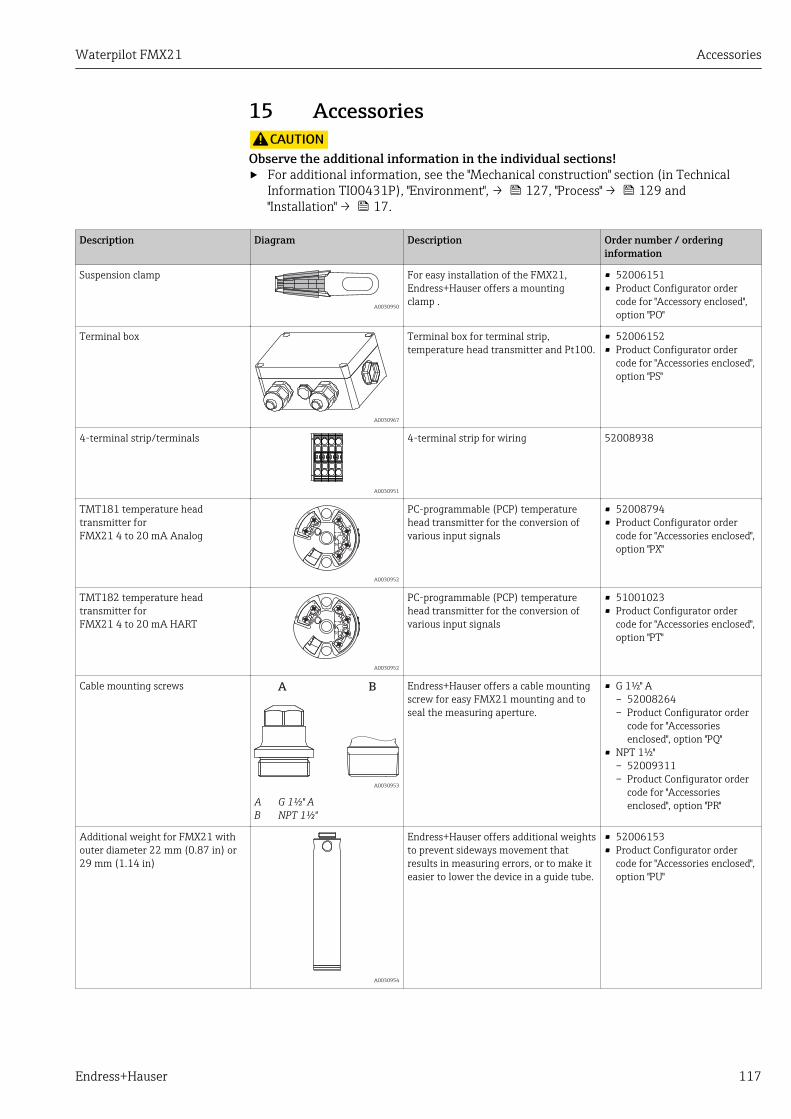
Waterpilot FMX21 Accessories
Endress+Hauser 117
15 AccessoriesLCAUTION
Observe the additional information in the individual sections!‣ For additional information, see the "Mechanical construction" section (in Technical
Information TI00431P), "Environment", → 127, "Process" → 129 and"Installation" → 17.
Description Diagram Description Order number / orderinginformation
Suspension clamp
A0030950
For easy installation of the FMX21,Endress+Hauser offers a mountingclamp .
• 52006151• Product Configurator order
code for "Accessory enclosed",option "PO"
Terminal box
A0030967
Terminal box for terminal strip,temperature head transmitter and Pt100.
• 52006152• Product Configurator order
code for "Accessories enclosed",option "PS"
4-terminal strip/terminals
A0030951
4-terminal strip for wiring 52008938
TMT181 temperature headtransmitter forFMX21 4 to 20 mA Analog
3
45
36
1
2
A0030952
PC-programmable (PCP) temperaturehead transmitter for the conversion ofvarious input signals
• 52008794• Product Configurator order
code for "Accessories enclosed",option "PX"
TMT182 temperature headtransmitter forFMX21 4 to 20 mA HART
3
45
36
1
2
A0030952
PC-programmable (PCP) temperaturehead transmitter for the conversion ofvarious input signals
• 51001023• Product Configurator order
code for "Accessories enclosed",option "PT"
Cable mounting screws A B
A0030953
A G 1½" AB NPT 1½"
Endress+Hauser offers a cable mountingscrew for easy FMX21 mounting and toseal the measuring aperture.
• G 1½" A– 52008264– Product Configurator order
code for "Accessoriesenclosed", option "PQ"
• NPT 1½"– 52009311– Product Configurator order
code for "Accessoriesenclosed", option "PR"
Additional weight for FMX21 withouter diameter 22 mm (0.87 in) or29 mm (1.14 in)
A0030954
Endress+Hauser offers additional weightsto prevent sideways movement thatresults in measuring errors, or to make iteasier to lower the device in a guide tube.
• 52006153• Product Configurator order
code for "Accessories enclosed",option "PU"
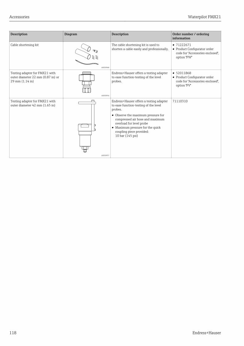
Accessories Waterpilot FMX21
118 Endress+Hauser
Description Diagram Description Order number / orderinginformation
Cable shortening kit
A0030948
The cable shortening kit is used toshorten a cable easily and professionally.
• 71222671• Product Configurator order
code for "Accessories enclosed",option "PW"
Testing adapter for FMX21 withouter diameter 22 mm (0.87 in) or29 mm (1.14 in)
A0030956
Endress+Hauser offers a testing adapterto ease function-testing of the levelprobes.
• 52011868• Product Configurator order
code for "Accessories enclosed",option "PV"
Testing adapter for FMX21 withouter diameter 42 mm (1.65 in)
A0030957
Endress+Hauser offers a testing adapterto ease function-testing of the levelprobes.
• Observe the maximum pressure forcompressed air hose and maximumoverload for level probe
• Maximum pressure for the quickcoupling piece provided:10 bar (145 psi)
71110310
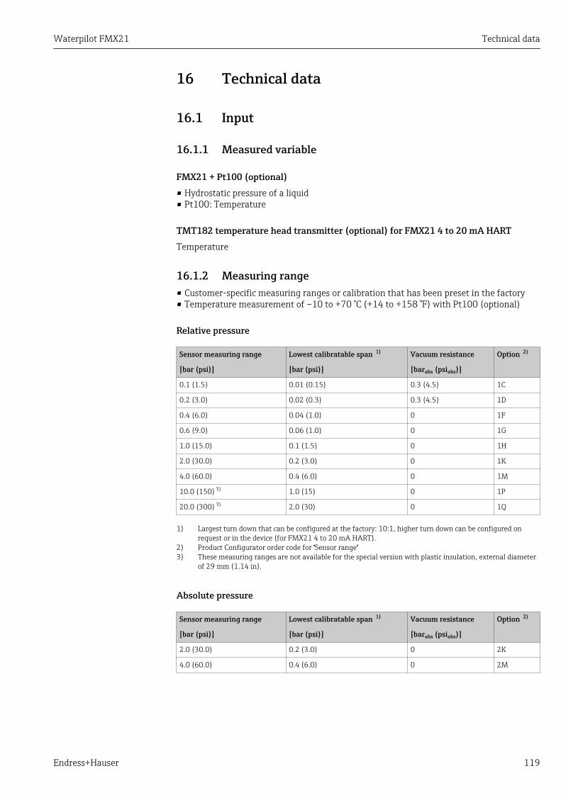
Waterpilot FMX21 Technical data
Endress+Hauser 119
16 Technical data
16.1 Input
16.1.1 Measured variable
FMX21 + Pt100 (optional)• Hydrostatic pressure of a liquid• Pt100: Temperature
TMT182 temperature head transmitter (optional) for FMX21 4 to 20 mA HARTTemperature
16.1.2 Measuring range• Customer-specific measuring ranges or calibration that has been preset in the factory• Temperature measurement of –10 to +70 °C (+14 to +158 °F) with Pt100 (optional)
Relative pressure
Sensor measuring range Lowest calibratable span 1) Vacuum resistance Option 2)
[bar (psi)] [bar (psi)] [barabs (psiabs)]
0.1 (1.5) 0.01 (0.15) 0.3 (4.5) 1C
0.2 (3.0) 0.02 (0.3) 0.3 (4.5) 1D
0.4 (6.0) 0.04 (1.0) 0 1F
0.6 (9.0) 0.06 (1.0) 0 1G
1.0 (15.0) 0.1 (1.5) 0 1H
2.0 (30.0) 0.2 (3.0) 0 1K
4.0 (60.0) 0.4 (6.0) 0 1M
10.0 (150) 3) 1.0 (15) 0 1P
20.0 (300) 3) 2.0 (30) 0 1Q
1) Largest turn down that can be configured at the factory: 10:1, higher turn down can be configured onrequest or in the device (for FMX21 4 to 20 mA HART).
2) Product Configurator order code for "Sensor range"3) These measuring ranges are not available for the special version with plastic insulation, external diameter
of 29 mm (1.14 in).
Absolute pressure
Sensor measuring range Lowest calibratable span 1) Vacuum resistance Option 2)
[bar (psi)] [bar (psi)] [barabs (psiabs)]
2.0 (30.0) 0.2 (3.0) 0 2K
4.0 (60.0) 0.4 (6.0) 0 2M
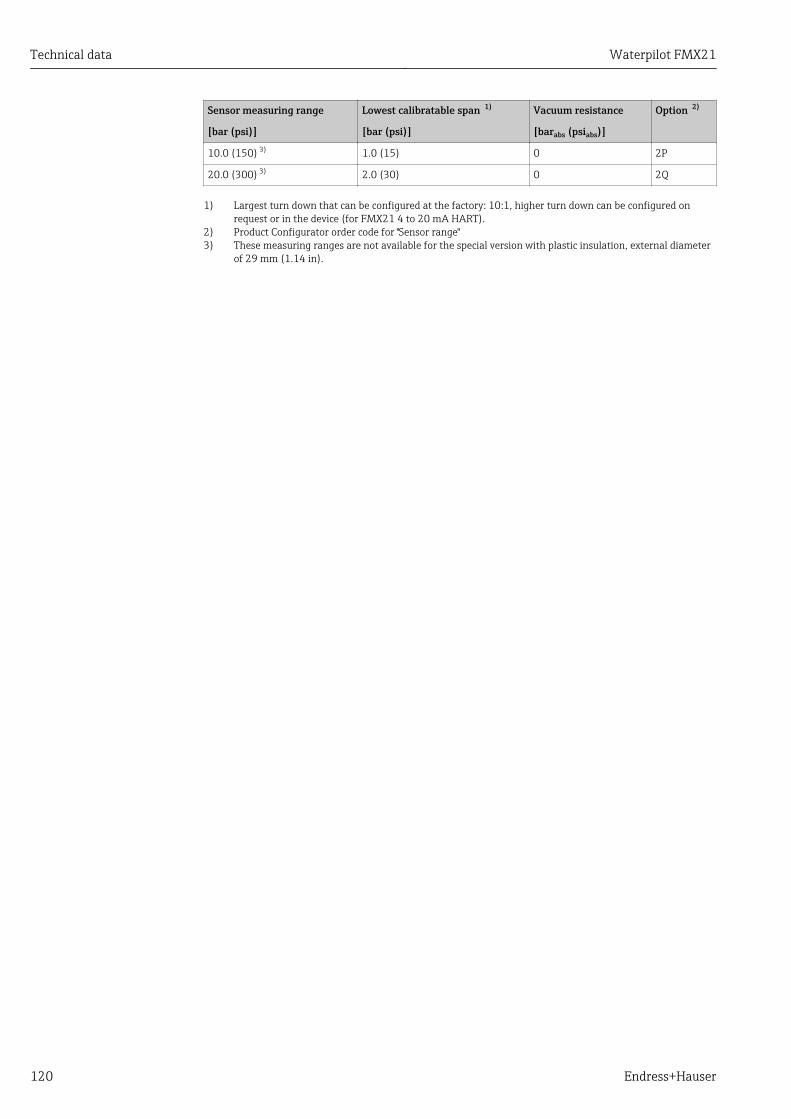
Technical data Waterpilot FMX21
120 Endress+Hauser
Sensor measuring range Lowest calibratable span 1) Vacuum resistance Option 2)
[bar (psi)] [bar (psi)] [barabs (psiabs)]
10.0 (150) 3) 1.0 (15) 0 2P
20.0 (300) 3) 2.0 (30) 0 2Q
1) Largest turn down that can be configured at the factory: 10:1, higher turn down can be configured onrequest or in the device (for FMX21 4 to 20 mA HART).
2) Product Configurator order code for "Sensor range"3) These measuring ranges are not available for the special version with plastic insulation, external diameter
of 29 mm (1.14 in).
Waterpilot FMX21 Technical data
Endress+Hauser 121
16.1.3 Input signal
FMX21 + Pt100 (optional)• Change in capacitance• Pt100: Change in resistance
TMT182 temperature head transmitter (optional) for FMX21 4 to 20 mA HARTPt100 resistance signal, 4 wire

Technical data Waterpilot FMX21
122 Endress+Hauser
16.2 Output
16.2.1 Output signal
FMX21 + Pt100 (optional)• 4 to 20 mA HART with superimposed digital communication protocol HART 6.0, 2-wire
for hydrostatic pressure measured value.Ordering information: Product Configurator order code for "Output", option "2"Options:– Max. alarm (factory setting 22mA): can be set from 21 to 23 mA– Hold measured value: last measured value is held– Min. alarm: 3.6 mA
• Pt100: temperature-dependent resistance value
TMT182 temperature head transmitter (optional) for FMX21 4 to 20 mA HART4 to 20 mA HART with superimposed digital communication protocol HART 5.0 fortemperature measured value, 2-wire
16.2.2 Signal range3.8 mA to 20.5 mA
16.2.3 Maximum load for FMX21 4 to 20 mA HARTThe maximum load resistance depends on the supply voltage (U) and must be determinedindividually for each current loop, see formula and diagrams for FMX21 and temperaturehead transmitter. The total resistance resulting from the resistances of the connecteddevices, the connecting cable and, where applicable, the resistance of the extension cablemay not exceed the load resistance value.

Waterpilot FMX21 Technical data
Endress+Hauser 123
RLmax – 2 0.09• • L – RU – 10.5 V
23 mA
W
m£
413
630
195
1065
3520 2510.5 15
847
30
R[ ]W
U
[ ]V
– RU – 11.5 V
0.023 A£RLmax
370
587
152
1022
3520 2511.5 15
804
30
R[ ]W
U
[ ]V
A B
add add
A0026500-EN
A FMX21 4 to 20 mA HART load chart for estimating the load resistance. Additional resistances, such as theresistance of the extension cable, have to be subtracted from the value calculated as shown in the equation.
B Load diagram for TMT182 temperature head transmitter for estimating the load resistance. Additionalresistances must be subtracted from the value calculated as shown in the equation
RLmaxMax. load resistance [Ω]Radd Additional resistances such as resistance of evaluating device and/or display unit, cable resistance [Ω]U Supply voltage [V]L Basic length of extension cable [m] (cable resistance per wire 0.09 Ω/m)
• When using the measuring device in hazardous areas, installation must complywith the corresponding national standards and regulations and the SafetyInstructions or Installation or Control Drawings (XA).
• When operating via a handheld terminal or via a PC with an operating program, aminimum communication resistance of 250 Ω must be taken into account.

Technical data Waterpilot FMX21
124 Endress+Hauser
16.2.4 Protocol-specific data for FMX21 4 to 20 mA HART
Manufacturer ID 17 (11 hex)
Device type code 25 (19 hex)
Device revision 01 (01 hex) - SW version 01.00.zz
HART specification 6
DD revision 01
Device description files(DTM, DD)
Information and files under:• www.endress.com• www.hartcomm.org
HART load Min. 250 Ω
HART device variables The dynamic variables SV, TV and QV may be assigned to any device variable:
Standard process values for SV, TV (second and third device variable) aredependent on the measuring mode:• Pressure• Level
Standard process value for QV (fourth device variable) is the sensortemperature:Temperature
Measured values for PV (first device variable) are dependent on themeasuring mode:• Pressure• Level• Tank content
Supported functions • Burst mode• Additional transmitter status• Device locking• Alternative measuring modes• Catch variable• Long tag

Waterpilot FMX21 Technical data
Endress+Hauser 125
16.3 Performance characteristics
16.3.1 Reference operating conditions
FMX21 + Pt100 (optional)• As per IEC 60770• Ambient temperature TU = constant, in the range of +21 to +33 °C (+70 to +91 °F)• Humidity φ = constant, in the range of 20 to 80 % rH• Ambient pressure pU = constant, in the range of 860 to 1 060 mbar (12.47 to 15.37 psi)• Position of measuring cell constant, vertical in the range of ±1°• Input of LOW SENSOR TRIM and HIGH SENSOR TRIM for lower range value and upper
range value (only for HART)• Supply voltage constant: 21 V DC to 27 V DC• Load with HART: 250 Ω• Pt100: DIN EN 60770, TU = +25 °C (+77 °F)
TMT182 temperature head transmitter (optional) for FMX21 4 to 20 mA HARTCalibration temperature +25 °C (+77 °F) ±5 K
16.3.2 Reference accuracy
FMX21 + Pt100 (optional)The reference accuracy comprises the non-linearity after limit point configuration,hysteresis and non-reproducibility in accordance IEC 60770.
Standard version 2):Setting ±0.2 %– to TD 5:1: < 0.2 % of set span– from TD 5:1 to TD 20:1 ±(0.02 x TD+0.1)
Platinum version 3):• Setting ±0.1 % (optional)
– to TD 5:1: < 0.1 % of set span– from TD 5:1 to TD 20:1 ±(0.02 x TD)
• Class B as per DIN EN 60751Pt100: max. ±1 K
TMT182 temperature head transmitter (optional) for FMX21 4 to 20 mA HART• ±0.2 K• With Pt100: max. ±0.9 K
16.3.3 ResolutionCurrent output: 1 μA
Reading cycleHART commands: on average 2 to 3 per second
2) Ordering information: Product Configurator order code for "Reference accuracy", option "G"3) Ordering information: Product Configurator order code for "Reference accuracy", option "D"

Technical data Waterpilot FMX21
126 Endress+Hauser
16.3.4 Long-term stability
FMX21 + Pt100 (optional)• ≤ 0.1 % of URL/year• ≤ 0.25 % of URL/5 years
TMT182 temperature head transmitter (optional) for FMX21 4 to 20 mA HART≤ 0.1 K per year
16.3.5 Influence of medium temperature• Thermal change in the zero output and the output span:
0 to +30 °C (+32 to +86 °F): < (0.15 + 0.15 x TD)% of set span–10 to +70 °C (+14 to +158 °F): < (0.4 + 0.4 x TD)% of set span
• Temperature coefficient (TK) of the zero output and the output span–10 to +70 °C (+14 to +158 °F): 0.1 % / 10 K of URL
16.3.6 Warm-up period
FMX21 + Pt100 (optional)• FMX21: < 6 s• Pt100: 20 m
TMT182 temperature head transmitter (optional) for FMX21 4 to 20 mA HART4 s
16.3.7 Response time
FMX21 + Pt100 (optional)• FMX21: 400 ms (T90 time), 500 ms (T99 time)• Pt100: 160 s (T90 time), 300 s (T99 time)
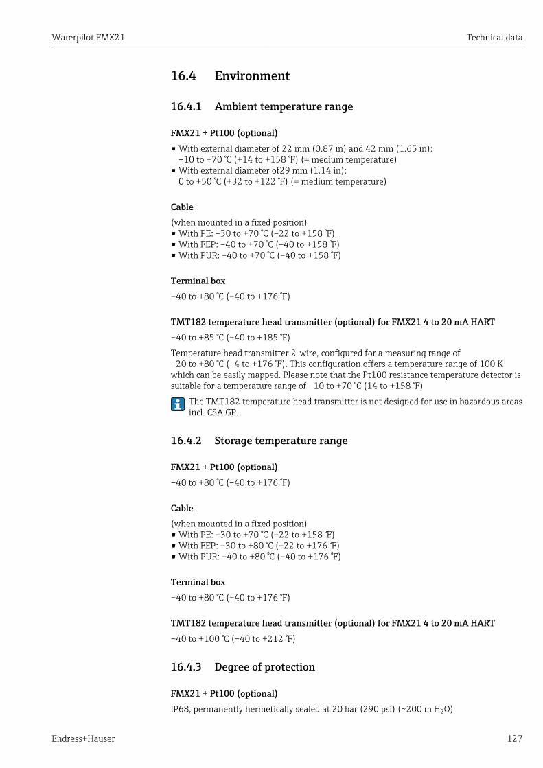
Waterpilot FMX21 Technical data
Endress+Hauser 127
16.4 Environment
16.4.1 Ambient temperature range
FMX21 + Pt100 (optional)• With external diameter of 22 mm (0.87 in) and 42 mm (1.65 in):
–10 to +70 °C (+14 to +158 °F) (= medium temperature)• With external diameter of29 mm (1.14 in):
0 to +50 °C (+32 to +122 °F) (= medium temperature)
Cable(when mounted in a fixed position)• With PE: –30 to +70 °C (–22 to +158 °F)• With FEP: –40 to +70 °C (–40 to +158 °F)• With PUR: –40 to +70 °C (–40 to +158 °F)
Terminal box–40 to +80 °C (–40 to +176 °F)
TMT182 temperature head transmitter (optional) for FMX21 4 to 20 mA HART–40 to +85 °C (–40 to +185 °F)
Temperature head transmitter 2-wire, configured for a measuring range of–20 to +80 °C (–4 to +176 °F). This configuration offers a temperature range of 100 Kwhich can be easily mapped. Please note that the Pt100 resistance temperature detector issuitable for a temperature range of –10 to +70 °C (14 to +158 °F)
The TMT182 temperature head transmitter is not designed for use in hazardous areasincl. CSA GP.
16.4.2 Storage temperature range
FMX21 + Pt100 (optional)–40 to +80 °C (–40 to +176 °F)
Cable(when mounted in a fixed position)• With PE: –30 to +70 °C (–22 to +158 °F)• With FEP: –30 to +80 °C (–22 to +176 °F)• With PUR: –40 to +80 °C (–40 to +176 °F)
Terminal box–40 to +80 °C (–40 to +176 °F)
TMT182 temperature head transmitter (optional) for FMX21 4 to 20 mA HART–40 to +100 °C (–40 to +212 °F)
16.4.3 Degree of protection
FMX21 + Pt100 (optional)IP68, permanently hermetically sealed at 20 bar (290 psi) (~200 m H2O)
Technical data Waterpilot FMX21
128 Endress+Hauser
Terminal box (optional)IP66, IP67
TMT182 temperature head transmitter (optional) for FMX21 4 to 20 mA HARTIP00, condensation permitted
16.4.4 Electromagnetic compatibility (EMC)
FMX21 + Pt100 (optional)• EMC in accordance with all relevant requirements of EN 61326 series. For details, refer
to the Declaration of Conformity.• Maximum deviation: < 0.5 % of span.
TMT182 temperature head transmitter (optional) for FMX21 4 to 20 mA HARTEMC in accordance with all relevant requirements of EN 61326 series. For details, refer tothe Declaration of Conformity.
16.4.5 Overvoltage protection
FMX21 + Pt100 (optional)• Integrated overvoltage protection as per EN 61000-4-5 (500 V symmetrical/1000 V
asymmetrical)• Overvoltage protection ≥ 1.0 kV, external if necessary
TMT182 temperature head transmitter (optional) for FMX21 4 to 20 mA HARTProvide overvoltage protection, externally if necessary (see Technical Information).

Waterpilot FMX21 Technical data
Endress+Hauser 129
16.5 Process
16.5.1 Medium temperature range
FMX21 + Pt100 (optional)• With external diameter of 22 mm (0.87 in) and 42 mm (1.65 in):
–10 to +70 °C (+14 to +158 °F)• With external diameter of 29 mm (1.14 in):
0 to +50 °C (+32 to +122 °F)
TMT181 temperature head transmitter (optional) for FMX21 4 to 20 mA HART–40 to +85 °C (–40 to +185 °F)
(= ambient temperature), install temperature head transmitter outside the medium.
Temperature head transmitter 2-wire, configured for a measuring range of–20 to +80 °C (–4 to +176 °F). This configuration offers a temperature range of 100 Kwhich can be easily mapped. Please note that the Pt100 resistance temperature detector issuitable for a temperature range of –10 to +70 °C (14 to +158 °F)
The TMT182 temperature head transmitter is not designed for use in hazardous areasincl. CSA GP.
16.5.2 Medium temperature limit
FMX21 + Pt100 (optional)With external diameter of 22 mm (0.87 in) and 42 mm (1.65 in):–20 to +70 °C (–4 to +158 °F)
In hazardous area incl. CSA GP, the medium temperature limit is–10 to +70 °C (+14 to +158 °F).
With external diameter of29 mm (1.14 in): 0 to +50 °C (+32 to +122 °F)
The FMX21 may be operated in this temperature range. The specification values, suchas accuracy, may be exceeded.
16.6 Additional technical dataSee Technical Information TI00431P.
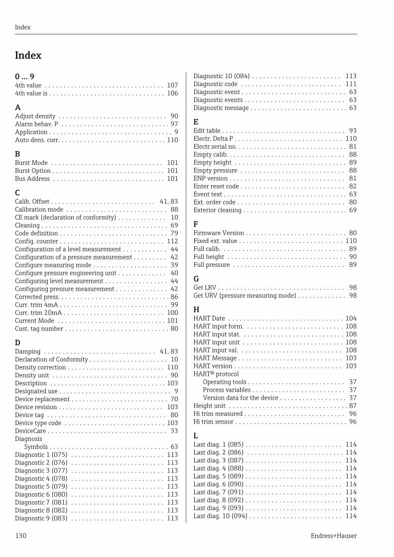
Index
130 Endress+Hauser
Index
0 … 94th value . . . . . . . . . . . . . . . . . . . . . . . . . . . . . . . . 1074th value is . . . . . . . . . . . . . . . . . . . . . . . . . . . . . . . 106
AAdjust density . . . . . . . . . . . . . . . . . . . . . . . . . . . . . 90Alarm behav. P . . . . . . . . . . . . . . . . . . . . . . . . . . . . . 97Application . . . . . . . . . . . . . . . . . . . . . . . . . . . . . . . . . 9Auto dens. corr. . . . . . . . . . . . . . . . . . . . . . . . . . . . . 110
BBurst Mode . . . . . . . . . . . . . . . . . . . . . . . . . . . . . . 101Burst Option . . . . . . . . . . . . . . . . . . . . . . . . . . . . . . 101Bus Address . . . . . . . . . . . . . . . . . . . . . . . . . . . . . . 101
CCalib. Offset . . . . . . . . . . . . . . . . . . . . . . . . . . . . 41, 83Calibration mode . . . . . . . . . . . . . . . . . . . . . . . . . . . 88CE mark (declaration of conformity) . . . . . . . . . . . . . 10Cleaning . . . . . . . . . . . . . . . . . . . . . . . . . . . . . . . . . . 69Code definition . . . . . . . . . . . . . . . . . . . . . . . . . . . . . 79Config. counter . . . . . . . . . . . . . . . . . . . . . . . . . . . . 112Configuration of a level measurement . . . . . . . . . . . . 44Configuration of a pressure measurement . . . . . . . . . 42Configure measuring mode . . . . . . . . . . . . . . . . . . . . 39Configure pressure engineering unit . . . . . . . . . . . . . 40Configuring level measurement . . . . . . . . . . . . . . . . . 44Configuring pressure measurement . . . . . . . . . . . . . . 42Corrected press. . . . . . . . . . . . . . . . . . . . . . . . . . . . . . 86Curr. trim 4mA . . . . . . . . . . . . . . . . . . . . . . . . . . . . . 99Curr. trim 20mA . . . . . . . . . . . . . . . . . . . . . . . . . . . 100Current Mode . . . . . . . . . . . . . . . . . . . . . . . . . . . . . 101Cust. tag number . . . . . . . . . . . . . . . . . . . . . . . . . . . . 80
DDamping . . . . . . . . . . . . . . . . . . . . . . . . . . . . . . 41, 83Declaration of Conformity . . . . . . . . . . . . . . . . . . . . . 10Density correction . . . . . . . . . . . . . . . . . . . . . . . . . . 110Density unit . . . . . . . . . . . . . . . . . . . . . . . . . . . . . . . 90Description . . . . . . . . . . . . . . . . . . . . . . . . . . . . . . . 103Designated use . . . . . . . . . . . . . . . . . . . . . . . . . . . . . . 9Device replacement . . . . . . . . . . . . . . . . . . . . . . . . . . 70Device revision . . . . . . . . . . . . . . . . . . . . . . . . . . . . 103Device tag . . . . . . . . . . . . . . . . . . . . . . . . . . . . . . . . 80Device type code . . . . . . . . . . . . . . . . . . . . . . . . . . . 103DeviceCare . . . . . . . . . . . . . . . . . . . . . . . . . . . . . . . . 33Diagnosis
Symbols . . . . . . . . . . . . . . . . . . . . . . . . . . . . . . . . 63Diagnostic 1 (075) . . . . . . . . . . . . . . . . . . . . . . . . . 113Diagnostic 2 (076) . . . . . . . . . . . . . . . . . . . . . . . . . 113Diagnostic 3 (077) . . . . . . . . . . . . . . . . . . . . . . . . . 113Diagnostic 4 (078) . . . . . . . . . . . . . . . . . . . . . . . . . 113Diagnostic 5 (079) . . . . . . . . . . . . . . . . . . . . . . . . . 113Diagnostic 6 (080) . . . . . . . . . . . . . . . . . . . . . . . . . 113Diagnostic 7 (081) . . . . . . . . . . . . . . . . . . . . . . . . . 113Diagnostic 8 (082) . . . . . . . . . . . . . . . . . . . . . . . . . 113Diagnostic 9 (083) . . . . . . . . . . . . . . . . . . . . . . . . . 113
Diagnostic 10 (084) . . . . . . . . . . . . . . . . . . . . . . . . 113Diagnostic code . . . . . . . . . . . . . . . . . . . . . . . . . . . 111Diagnostic event . . . . . . . . . . . . . . . . . . . . . . . . . . . . 63Diagnostic events . . . . . . . . . . . . . . . . . . . . . . . . . . . 63Diagnostic message . . . . . . . . . . . . . . . . . . . . . . . . . . 63
EEdit table . . . . . . . . . . . . . . . . . . . . . . . . . . . . . . . . . 93Electr. Delta P . . . . . . . . . . . . . . . . . . . . . . . . . . . . . 110Electr.serial no. . . . . . . . . . . . . . . . . . . . . . . . . . . . . . 81Empty calib. . . . . . . . . . . . . . . . . . . . . . . . . . . . . . . . 88Empty height . . . . . . . . . . . . . . . . . . . . . . . . . . . . . . 89Empty pressure . . . . . . . . . . . . . . . . . . . . . . . . . . . . 88ENP version . . . . . . . . . . . . . . . . . . . . . . . . . . . . . . . 81Enter reset code . . . . . . . . . . . . . . . . . . . . . . . . . . . . 82Event text . . . . . . . . . . . . . . . . . . . . . . . . . . . . . . . . . 63Ext. order code . . . . . . . . . . . . . . . . . . . . . . . . . . . . . 80Exterior cleaning . . . . . . . . . . . . . . . . . . . . . . . . . . . . 69
FFirmware Version . . . . . . . . . . . . . . . . . . . . . . . . . . . 80Fixed ext. value . . . . . . . . . . . . . . . . . . . . . . . . . . . . 110Full calib. . . . . . . . . . . . . . . . . . . . . . . . . . . . . . . . . . 89Full height . . . . . . . . . . . . . . . . . . . . . . . . . . . . . . . . 90Full pressure . . . . . . . . . . . . . . . . . . . . . . . . . . . . . . 89
GGet LRV . . . . . . . . . . . . . . . . . . . . . . . . . . . . . . . . . . 98Get URV (pressure measuring mode) . . . . . . . . . . . . . 98
HHART Date . . . . . . . . . . . . . . . . . . . . . . . . . . . . . . . 104HART input form. . . . . . . . . . . . . . . . . . . . . . . . . . . 108HART input stat. . . . . . . . . . . . . . . . . . . . . . . . . . . . 108HART input unit . . . . . . . . . . . . . . . . . . . . . . . . . . . 108HART input val. . . . . . . . . . . . . . . . . . . . . . . . . . . . 108HART Message . . . . . . . . . . . . . . . . . . . . . . . . . . . . 103HART version . . . . . . . . . . . . . . . . . . . . . . . . . . . . . 103HART® protocol
Operating tools . . . . . . . . . . . . . . . . . . . . . . . . . . 37Process variables . . . . . . . . . . . . . . . . . . . . . . . . . 37Version data for the device . . . . . . . . . . . . . . . . . . 37
Height unit . . . . . . . . . . . . . . . . . . . . . . . . . . . . . . . . 87Hi trim measured . . . . . . . . . . . . . . . . . . . . . . . . . . . 96Hi trim sensor . . . . . . . . . . . . . . . . . . . . . . . . . . . . . . 96
LLast diag. 1 (085) . . . . . . . . . . . . . . . . . . . . . . . . . . 114Last diag. 2 (086) . . . . . . . . . . . . . . . . . . . . . . . . . . 114Last diag. 3 (087) . . . . . . . . . . . . . . . . . . . . . . . . . . 114Last diag. 4 (088) . . . . . . . . . . . . . . . . . . . . . . . . . . 114Last diag. 5 (089) . . . . . . . . . . . . . . . . . . . . . . . . . . 114Last diag. 6 (090) . . . . . . . . . . . . . . . . . . . . . . . . . . 114Last diag. 7 (091) . . . . . . . . . . . . . . . . . . . . . . . . . . 114Last diag. 8 (092) . . . . . . . . . . . . . . . . . . . . . . . . . . 114Last diag. 9 (093) . . . . . . . . . . . . . . . . . . . . . . . . . . 114Last diag. 10 (094) . . . . . . . . . . . . . . . . . . . . . . . . . 114
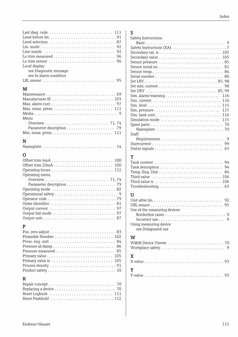
Index
Endress+Hauser 131
Last diag. code . . . . . . . . . . . . . . . . . . . . . . . . . . . . 111Level before lin. . . . . . . . . . . . . . . . . . . . . . . . . . . . . . 91Level selection . . . . . . . . . . . . . . . . . . . . . . . . . . . . . 87Lin. mode . . . . . . . . . . . . . . . . . . . . . . . . . . . . . . . . . 92Line-numb. . . . . . . . . . . . . . . . . . . . . . . . . . . . . . . . 92Lo trim measured . . . . . . . . . . . . . . . . . . . . . . . . . . . 96Lo trim sensor . . . . . . . . . . . . . . . . . . . . . . . . . . . . . 96Local display
see Diagnostic messagesee In alarm condition
LRL sensor . . . . . . . . . . . . . . . . . . . . . . . . . . . . . . . . 95
MMaintenance . . . . . . . . . . . . . . . . . . . . . . . . . . . . . . . 69Manufacturer ID . . . . . . . . . . . . . . . . . . . . . . . . . . . 103Max. alarm curr. . . . . . . . . . . . . . . . . . . . . . . . . . . . . 97Max. meas. press. . . . . . . . . . . . . . . . . . . . . . . . . . . 111Media . . . . . . . . . . . . . . . . . . . . . . . . . . . . . . . . . . . . . 9Menu
Overview . . . . . . . . . . . . . . . . . . . . . . . . . . . . 71, 74Parameter description . . . . . . . . . . . . . . . . . . . . . 79
Min. meas. press. . . . . . . . . . . . . . . . . . . . . . . . . . . 111
NNameplate . . . . . . . . . . . . . . . . . . . . . . . . . . . . . . . . 14
OOffset trim 4mA . . . . . . . . . . . . . . . . . . . . . . . . . . . 100Offset trim 20mA . . . . . . . . . . . . . . . . . . . . . . . . . . 100Operating hours . . . . . . . . . . . . . . . . . . . . . . . . . . . 112Operating menu
Overview . . . . . . . . . . . . . . . . . . . . . . . . . . . . 71, 74Parameter description . . . . . . . . . . . . . . . . . . . . . 79
Operating mode . . . . . . . . . . . . . . . . . . . . . . . . . . . . 82Operational safety . . . . . . . . . . . . . . . . . . . . . . . . . . . . 9Operator code . . . . . . . . . . . . . . . . . . . . . . . . . . . . . . 79Order Identifier . . . . . . . . . . . . . . . . . . . . . . . . . . . . . 81Output current . . . . . . . . . . . . . . . . . . . . . . . . . . . . . 97Output fail mode . . . . . . . . . . . . . . . . . . . . . . . . . . . . 97Output unit . . . . . . . . . . . . . . . . . . . . . . . . . . . . . . . . 87
PPos. zero adjust . . . . . . . . . . . . . . . . . . . . . . . . . . . . . 83Preamble Number . . . . . . . . . . . . . . . . . . . . . . . . . . 102Press. eng. unit . . . . . . . . . . . . . . . . . . . . . . . . . . . . . 84Pressure af.damp . . . . . . . . . . . . . . . . . . . . . . . . . . . 86Pressure measured . . . . . . . . . . . . . . . . . . . . . . . . . . 85Primary value . . . . . . . . . . . . . . . . . . . . . . . . . . . . . 105Primary value is . . . . . . . . . . . . . . . . . . . . . . . . . . . 105Process density . . . . . . . . . . . . . . . . . . . . . . . . . . . . . 91Product safety . . . . . . . . . . . . . . . . . . . . . . . . . . . . . . 10
RRepair concept . . . . . . . . . . . . . . . . . . . . . . . . . . . . . 70Replacing a device . . . . . . . . . . . . . . . . . . . . . . . . . . . 70Reset Logbook . . . . . . . . . . . . . . . . . . . . . . . . . . . . 111Reset Peakhold . . . . . . . . . . . . . . . . . . . . . . . . . . . . 112
SSafety Instructions
Basic . . . . . . . . . . . . . . . . . . . . . . . . . . . . . . . . . . . 9Safety Instructions (XA) . . . . . . . . . . . . . . . . . . . . . . . . 7Secondary val. is . . . . . . . . . . . . . . . . . . . . . . . . . . . 105Secondary value . . . . . . . . . . . . . . . . . . . . . . . . . . . 105Sensor pressure . . . . . . . . . . . . . . . . . . . . . . . . . . . . . 85Sensor serial no. . . . . . . . . . . . . . . . . . . . . . . . . . . . . 81Sensor temp. . . . . . . . . . . . . . . . . . . . . . . . . . . . . . . . 84Serial number . . . . . . . . . . . . . . . . . . . . . . . . . . . . . . 80Set LRV . . . . . . . . . . . . . . . . . . . . . . . . . . . . . . . . 85, 98Set min. current . . . . . . . . . . . . . . . . . . . . . . . . . . . . 98Set URV . . . . . . . . . . . . . . . . . . . . . . . . . . . . . . . 85, 99Sim. alarm/warning . . . . . . . . . . . . . . . . . . . . . . . . 116Sim. current . . . . . . . . . . . . . . . . . . . . . . . . . . . . . . 116Sim. level . . . . . . . . . . . . . . . . . . . . . . . . . . . . . . . . 115Sim. pressure . . . . . . . . . . . . . . . . . . . . . . . . . . . . . 115Sim. tank cont. . . . . . . . . . . . . . . . . . . . . . . . . . . . . 116Simulation mode . . . . . . . . . . . . . . . . . . . . . . . . . . 115Spare parts . . . . . . . . . . . . . . . . . . . . . . . . . . . . . . . . 70
Nameplate . . . . . . . . . . . . . . . . . . . . . . . . . . . . . . 70Staff
Requirements . . . . . . . . . . . . . . . . . . . . . . . . . . . . . 9Startcurrent . . . . . . . . . . . . . . . . . . . . . . . . . . . . . . . 99Status signals . . . . . . . . . . . . . . . . . . . . . . . . . . . . . . 63
TTank content . . . . . . . . . . . . . . . . . . . . . . . . . . . . . . 94Tank description . . . . . . . . . . . . . . . . . . . . . . . . . . . . 94Temp. Eng. Unit . . . . . . . . . . . . . . . . . . . . . . . . . . . . 84Third value . . . . . . . . . . . . . . . . . . . . . . . . . . . . . . . 106Third value is . . . . . . . . . . . . . . . . . . . . . . . . . . . . . 106Troubleshooting . . . . . . . . . . . . . . . . . . . . . . . . . . . . 63
UUnit after lin. . . . . . . . . . . . . . . . . . . . . . . . . . . . . . . 92URL sensor . . . . . . . . . . . . . . . . . . . . . . . . . . . . . . . . 95Use of the measuring devices
Borderline cases . . . . . . . . . . . . . . . . . . . . . . . . . . . 9Incorrect use . . . . . . . . . . . . . . . . . . . . . . . . . . . . . 9
Using measuring devicesee Designated use
WW@M Device Viewer . . . . . . . . . . . . . . . . . . . . . . . . . 70Workplace safety . . . . . . . . . . . . . . . . . . . . . . . . . . . . 9
XX-value . . . . . . . . . . . . . . . . . . . . . . . . . . . . . . . . . . . 93
YY-value . . . . . . . . . . . . . . . . . . . . . . . . . . . . . . . . . . 93

www.addresses.endress.com
*71344391*71344391