water treatment plant - walsh estimating service plant site sample… · · 2010-03-31water...
TRANSCRIPT
Water Treatment PlantSite Construction
Sample
Prepared: 5/25/2007
Final Version 1.0
Prepared For:
Water Plant Constructors
This takeoff has been prepared by Walsh Estimating Service , a division of Maracorp International:
Although we have been careful to assure that all items are correct, we make no guarantee beyond the cost of ourwork. The contractor has the final responsibility for completeness and accuracy in the preparation of his bid.
By acceptance of this takeoff, the purchaser agrees to the following statement:
"I do hereby release and hold harmless Walsh Estimating Service, Maracorp International, Ed Walsh, and hisemployees from any and all errors and omissions beyond the invoiced value of services rendered."
Takeoff By: Walsh Estimating (570) 223-7880
Page 2 of 39 Water Plant Site Sample.xls 1.0 printed 6/29/20072:00 PM
ITEM UNIT QUANT PRICE AMOUNTWater Treatment Plant
Site ConstructionSample
Prepared: 5/25/2007
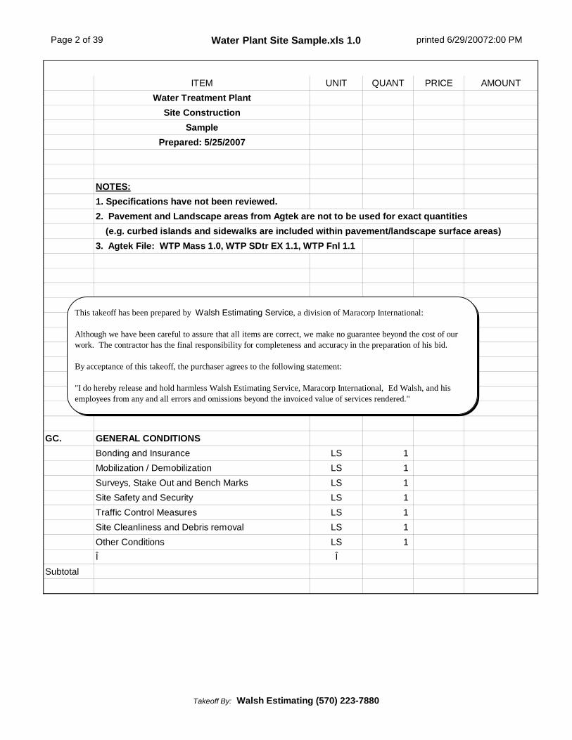
NOTES:1. Specifications have not been reviewed.2. Pavement and Landscape areas from Agtek are not to be used for exact quantities (e.g. curbed islands and sidewalks are included within pavement/landscape surface areas)3. Agtek File: WTP Mass 1.0, WTP SDtr EX 1.1, WTP Fnl 1.1
GC. GENERAL CONDITIONSBonding and Insurance LS 1Mobilization / Demobilization LS 1Surveys, Stake Out and Bench Marks LS 1Site Safety and Security LS 1Traffic Control Measures LS 1Site Cleanliness and Debris removal LS 1Other Conditions LS 1Î Î
Subtotal
This takeoff has been prepared by Walsh Estimating Service, a division of Maracorp International:
Although we have been careful to assure that all items are correct, we make no guarantee beyond the cost of ourwork. The contractor has the final responsibility for completeness and accuracy in the preparation of his bid.
By acceptance of this takeoff, the purchaser agrees to the following statement:
"I do hereby release and hold harmless Walsh Estimating Service, Maracorp International, Ed Walsh, and hisemployees from any and all errors and omissions beyond the invoiced value of services rendered."
Takeoff By: Walsh Estimating (570) 223-7880

Page 3 of 39 Water Plant Site Sample.xls 1.0 printed 6/29/20072:00 PM
ITEM UNIT QUANT PRICE AMOUNTI. EROSION AND SEDIMENT CONTROL
General ItemsConstruction Entrance Pad, 8" thick CY 25
Class 3 Filter Fabric for construction entrance pad SY 110
Inlet Filters, (type) EA 11Silt Fence, 30" high with tie backs and reinforcingmesh if required LF 460
Super Silt Fence SF-30, 33" high with chain linkfence, tension wire and mounted on 2-1/2"galvanized or aluminum posts set 30" deep
LF 580
Temporary Diversion Channel with downslopeberm, 2'-6" deep x 2' bottom width with 2H:1Vslopes
LF 350
Jute or Excelsior Lining for diversion channel SY 817Temporary Rock Filter in swale EA 1Temporary 15" HDPE LF 70Temporary Riser, Perforated as required 24" CMP,3'+/- high and set in 36" square x 18" thick concretefooting
LS 1
Trash Rack and Anti Vortex Device, 36" diameter x27" high with welded top closure LS 1
Temporary 18" CMP stub to riser LF 10
Pyramat for Sediment Basin Emergency Spillway, 8'-6" wide material (lose 5' per 30' run for key trench),incl 17% for overlap and key trench
SY 275
High Performance Turf reinforcement Mat (Pyramator equal) for steep slopes, 8'-6" wide material (lose5' per 30' run for key trench), incl 17% for overlapand key trench
SY 7,300
Temporary seeding as required LS 1Sediment TrapArea, 12' x 70' SF 840
Assume Earth Berm required on 2 sides, 36"+/- high LF 82
R-3 Rock Berm, 5' crest width with 12" No.57 stonelayer on face LF 12
Approximate R-3 Rock CY 16Approximate No. 57 Rock CY 3
Takeoff By: Walsh Estimating (570) 223-7880

Page 4 of 39 Water Plant Site Sample.xls 1.0 printed 6/29/20072:00 PM
ITEM UNIT QUANT PRICE AMOUNTTemporary Level SpreaderLength LF 25Excavation, 3'+/- wide x 3' deep CY 8Backfill CY 4
Excess (See Mass Earthwork Overall Summary) CY 4
Reinforced Concrete Footing, 1'-6" wide x 12" thick CY 1
Reinforced Concrete Wall, 2'-0" high x 6" thick CY 1R-4 Rip Rap, 2'-0" wide x 12" thick CY 2Geotextile SY 8Trench PlugsBurlap filled sacks, 24" x 12'+/- total height (8"below finish surface) over 24" finished water and 6"force main sewer, approximate trench width 9'+/-, 3each
CY 25
Burlap filled sacks, 24" x 9'+/- total height (8" belowfinish surface) over 24" raw water and 24" wastewater, approximate trench width 10'+/-, 3 each
CY 20
Stream Crossing
Temporary Cofferdam of earth filled sacks withClass 3 Geotextile lining for 15'+/- crossing and 12"freeboard, 2 uses NOTE: Alternate: JerseyBarrier with impermeable fabric or Portable Dam
LS 1
Permanent Swale LengthSwale No. 3, 4' wide LF 150Swale No. 5, 4' wide LF 110Swale No. 6, 6' wide LF 80Swale No. 7, 6' wide LF 380Swale No. 8, 6' wide LF 80Swale No. 9, 6' wide LF 260Swale No. 10, 19' wide LF 350
Total = LF 1,410Swale LiningPyramat, 8'-6" wide (lose 5' per 30' run for keytrench), incl 17% for overlap and key trench SY 1,625
Î ÎSubtotal
Takeoff By: Walsh Estimating (570) 223-7880

Page 5 of 39 Water Plant Site Sample.xls 1.0 printed 6/29/20072:00 PM
ITEM UNIT QUANT PRICE AMOUNTII. SITE CLEARING AND DEMOLITION
Clear, Grub and Dispose Trees and Stumps to 10'outside fence line AC 0.61
Saw Cut Pavement NOTE: This is included withpavement section below. LF
Remove Curb NOTE: Contours do not indicateexisting curb. LF
Subtotal
III. EXCAVATION (All volumes are "Raw" -- noassumptions for swell or compaction)DISTURBANCE AREA SF 224,913Disturbance Area, Acres Acre 5.16Î ÎStrip Topsoil Areas, 12" thick CY 4,165
*********SUBGRADE ASSUMPTIONS:Basin and Swale 0.50'Pavement Areas 1.17'Mass grade landscape and slope areas, excludingplant footprint 0.50'
Structure Excavation with 4'-6' clearance and1H:1V slopes var.
Structure Backfill interior (820 cy is deep tanklayback backfill, balance is layback under adminsection of building and 3'+/- average fill under slab)
var.
Structure Backfill exterior under landscape
Final grade around plant, landscape areas 0.50'
Final grade around plant, pavement areas 1.17'
*********
EARTH CUT:Basin and Swale CY 2,414Pavement Areas CY 7,468Mass grade landscape and slope areas, excludingplant footprint CY 12,053
Structure Excavation with 4'-6' clearance and 1H:1Vslopes CY 31,921
Final grade around plant, landscape areas CY 1,368
TOTAL EARTH CUT = CY 55,224
Takeoff By: Walsh Estimating (570) 223-7880

Page 6 of 39 Water Plant Site Sample.xls 1.0 printed 6/29/20072:00 PM
ITEM UNIT QUANT PRICE AMOUNTROCK CUT:Basin and Swale CYPavement Areas CY 736Mass grade landscape and slope areas, excludingplant footprint CY 799
Structure Excavation with 4'-6' clearance and 1H:1Vslopes CY 5,815
TOTAL ROCK CUT = CY 7,350UNCLASSIFIED FILL:Basin and Swale CY 2,211Pavement Areas CY 144Mass grade landscape and slope areas, excludingplant footprint CY 201
Structure Backfill interior (820 cy is deep tanklayback backfill, balance is layback under adminsection of building and 3'+/- average fill under slab)
CY 6,012
Structure Backfill exterior under landscape CY 12,328Final grade around plant, pavement areas CY 1,130
TOTAL FILL = CY 22,026*********
UNCLASSIFIED EXCESS (BORROW) = CY 40,548*********
OVERALL UNCLASSIFIED SUMMARY:Unclassified Excess (Borrow) CY 40,548Footing Excavation Excess CY 111Pipe Trench Excess CY 4,772Rip Rap Excess CY 98
TOTAL EXCESS (BORROW) = CY 45,529
Î Î
TOPSOIL SUMMARY:Strip Volume CY 4,165
Required Volume, 6'' thick CY 2,717EXCESS (BORROW) TOPSOIL = CY 1,448
Î ÎSubtotal
Takeoff By: Walsh Estimating (570) 223-7880

Page 7 of 39 Water Plant Site Sample.xls 1.0 printed 6/29/20072:00 PM
ITEM UNIT QUANT PRICE AMOUNT
III-1. ROCK BLASTING (AND REMOVAL) - If Required(Unit Price)Mass Rock Blasting CY 7,350Trench Rock Blasting (0'-6' deep) LFTrench Rock Blasting (6'-9' deep) LFTrench Rock Blasting (9'-12' deep) LFTrench Rock Blasting (12'-15' deep) LFÎ Î
Subtotal
IV. ROUGH GRADING AREASImportant NOTE: Pavement and Landscape areas from Agtek printout are not to be used for exact quantities
(e.g. curbed islands and sidewalks are usually included within pavement/landscape surface areas)Grading AreasBasin and Swale SY 5,868Pavement Areas SY 4,675Mass grade landscape and slope areas, excludingplant footprint SY 6,076
Structure Excavation with 4'-6' clearance and 1H:1Vslopes SY 5,349
Structure Backfill interior (820 cy is deep tanklayback backfill, balance is layback under adminsection of building and 3'+/- average fill under slab)
SY 1,959
Structure Backfill exterior under landscape SY 2,846Final grade around plant, landscape areas SY 5,112Final grade around plant, pavement areas SY 1,478adjust for overlapping area SY (33,362)Disturbance Area SY 24,990
Total = SY 24,991check SY 24,990
Subtotal
V. TOPSOIL REDISTRIBUTION AREATopsoil Redistribution SY 16,316Seed and Mulch SY 16,316
Subtotal
Takeoff By: Walsh Estimating (570) 223-7880

Page 8 of 39 Water Plant Site Sample.xls 1.0 printed 6/29/20072:00 PM
ITEM UNIT QUANT PRICE AMOUNT
VI. BUILDING EXCAVATIONArea ReferenceCarbon Feed Building Area (for reference only) SF 600Water Plant Area (for reference only) SF 33,125Stone Under SlabStone Under Slab, _" thick SF 33,125Carbon Building and Chemical/Admin BuildingFooting Excavation and BackfillExcavation CY 339Backfill CY 228
Excess (See Mass Earthwork Overall Summary) CY 111
Î ÎSubtotal
VII. SANITARY SEWERPipe Excavation and BeddingExcavation CY 1,750Bedding -- Assume 6" thick and 12" cover CY 320Select Backfill CY 290Common Backfill CY 1,129
Excess (See Mass Earthwork Overall Summary) CY 621
12" thick Clay Cap in Roosevelt Street CY 11Services
4" Cleanout Assembly with Neenah H20 Cast IronFrame and Cover set on concrete slab, 6" thick EA 3
4" PVC Lateral in pavement (0'-4' deep) LF 210PipeNOTE: Install sewer force main prior to installationof remaining water pipelines.4" restrained joint DIP Force Main (6'-8' deep) LF 506" restrained joint DIP Force Main (6'-8' deep) LF 3006" restrained joint DIP Force Main down streambanks (6'-8' deep) LF 45
6" restrained joint DIP Force Main in existing paveddriveway (6'-8' deep) LF 12
Takeoff By: Walsh Estimating (570) 223-7880

Page 9 of 39 Water Plant Site Sample.xls 1.0 printed 6/29/20072:00 PM
ITEM UNIT QUANT PRICE AMOUNT6" restrained joint DIP Force Main in Spring Creek(6'-8' deep) LF 15
6" restrained joint DIP Force Main (8'-10' deep) LF 1106" restrained joint DIP Force Main (10'-12' deep) LF 4786" restrained joint DIP Force Main in RooseveltStreet pavement (12'-14' deep) LF 75
6" restrained joint DIP Force Main (14'-16' deep) LF 1006" restrained joint DIP Force Main in pavement (12'-14' deep) LF 75
Total = LF 1,260pipe check 1,260
Fittings and Valves4" PVC 22-1/2 degree Bend vertical EA 24" x 4" x 4" PVC Wye EA 34" DIP 22-1/2 degree Bend vertical EA 14" DIP 45 degree Bend horizontal EA 16" DIP 45 degree Bend horizontal EA 76" DIP 45 degree Bend vertical EA 46" x 6" x 6" DIP Wye EA 16" DIP 11-1/4 degree Bend horizontal EA 26" DIP 22-1/2 degree Bend horizontal EA 26" DIP 22-1/2 degree Bend vertical EA 16" x 6" x 6" Tapping Sleeve and Valve EA 16" Wet Tap EA 1
Total = EA 26structure check 26
Meter Manhole4'-0" diameter x 6'-6" deep Precast Concrete withflat slab top, Neenah R-1916-D manhole frame withbolted and gasketed cover and 4" concrete fillsloped to sump
EA 1
4" Flanged Adapter with anchor studs EA 24" Mag Meter EA 1Pump Station6'-0" diameter x 10' deep Precast Concrete with flatslab top for H20 loading, 16"+/- riser, and Bilco J-4AL Double Door Access Hatch
LS 1
Duplex Pumps and Controls with 2" discharge andcheck valves EA 2
Takeoff By: Walsh Estimating (570) 223-7880

Page 10 of 39 Water Plant Site Sample.xls 1.0 printed 6/29/20072:00 PM
ITEM UNIT QUANT PRICE AMOUNTConcrete EncasementConcrete Encasement LF 60Hand Placed R-5 Volume, 36" thick in earth CY 20Î Î
Subtotal
VIII. RAW WATER, FINISHED WATER, SERVICE WATER AND WASTEWATERPipe Excavation and BeddingExcavation CY 7,410Bedding -- Assume 6" thick and 12" cover CY 1,9502RC Select Backfill CY 1,200Common Backfill CY 3,747
Excess (See Mass Earthwork Overall Summary) CY 3,663
12" thick Clay Cap in Roosevelt Street CY 33Raw Water Sample Pipe3/4" Copper B-RWS laid in trench with 24" rawwater LF 28
Plant Service Water2" Service Water, assume copper (4'-6' deep) LF 854" restrained joint DIP in pavement (4'-6' deep) LF 65Water Supply2-1/2" restrained joint DIP (6'-8' deep) LF 504" restrained joint DIP (6'-8' deep) LF 354" restrained joint DIP in existing gravel driveway (6'-8' deep) LF 170
4" restrained joint DIP in existing paved driveway (6'-8' deep) LF 211
4" DIP Drain (6'-8' deep) LF 45Raw Water Pipe16" restrained joint DIP in existing paved driveway(0'-6' deep) LF 37
24" restrained joint DIP (0'-6' deep) LF 7524" restrained joint DIP (6'-8' deep) LF 36024" restrained joint DIP in existing paved driveway(6'-8' deep) LF 145
24" restrained joint DIP in pavement (0'-6' deep) LF 175
Takeoff By: Walsh Estimating (570) 223-7880

Page 11 of 39 Water Plant Site Sample.xls 1.0 printed 6/29/20072:00 PM
ITEM UNIT QUANT PRICE AMOUNT24" restrained joint DIP in common trench (WMHNo. 3 to WMH No.6) (0'-6' deep) LF 325
24" restrained joint DIP in common trench (WMHNo. 3 to WMH No.6) (6'-8' deep) LF 200
24" restrained joint DIP in Roosevelt Streetpavement (6'-8' deep) LF 100
24" restrained joint DIP in common trench (WMHNo. 3 to WMH No.6) (8'-10' deep) LF 210
Total = LF 1,627pipe check 1,627
Finished Water Pipe6" restrained joint DIP (6'-8' deep) LF 1024" restrained joint DIP (6'-8' deep) LF 10524" restrained joint DIP in existing paved driveway(6'-8' deep) LF 32
24" restrained joint DIP Force Main down streambanks (6'-8' deep) LF 50
24" restrained joint DIP Force Main in Spring Creek(6'-8' deep) LF 15
24" restrained joint DIP (8'-10' deep) LF 5824" restrained joint DIP (12'-14' deep) LF 42
24" restrained joint DIP in pavement (0'-6' deep) LF 70
24" restrained joint DIP in pavement (12'-14' deep) LF 35
24" restrained joint DIP in common trench (WMHNo. 3 to WMH No.6) (0'-6' deep) LF 145
24" restrained joint DIP in common trench (WMHNo. 3 to WMH No.6) (6'-8' deep) LF 265
24" restrained joint DIP in common trench inRoosevelt Street (WMH No. 3 to WMH No.6) (6'-8'deep)
LF 60
24" restrained joint DIP in common trench (WMHNo. 3 to WMH No.6) (8'-10' deep) LF 260
24" restrained joint DIP in common trench (WMHNo. 3 to WMH No.6) (10'-12' deep) LF 65
Total = LF 1,212pipe check 1,212
Wastewater Pipe24" restrained joint DIP (0'-6' deep) LF 3824" restrained joint DIP in existing paved driveway(0'-6' deep) LF 12
24" restrained joint DIP (16'-18' deep) LF 65
Takeoff By: Walsh Estimating (570) 223-7880
Page 12 of 39 Water Plant Site Sample.xls 1.0 printed 6/29/20072:00 PM
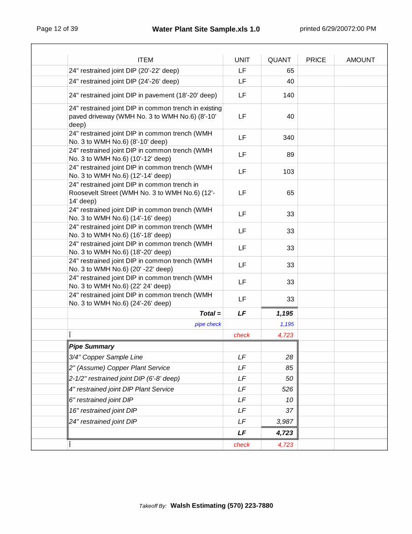
ITEM UNIT QUANT PRICE AMOUNT24" restrained joint DIP (20'-22' deep) LF 6524" restrained joint DIP (24'-26' deep) LF 40
24" restrained joint DIP in pavement (18'-20' deep) LF 140
24" restrained joint DIP in common trench in existingpaved driveway (WMH No. 3 to WMH No.6) (8'-10'deep)
LF 40
24" restrained joint DIP in common trench (WMHNo. 3 to WMH No.6) (8'-10' deep) LF 340
24" restrained joint DIP in common trench (WMHNo. 3 to WMH No.6) (10'-12' deep) LF 89
24" restrained joint DIP in common trench (WMHNo. 3 to WMH No.6) (12'-14' deep) LF 103
24" restrained joint DIP in common trench inRoosevelt Street (WMH No. 3 to WMH No.6) (12'-14' deep)
LF 65
24" restrained joint DIP in common trench (WMHNo. 3 to WMH No.6) (14'-16' deep) LF 33
24" restrained joint DIP in common trench (WMHNo. 3 to WMH No.6) (16'-18' deep) LF 33
24" restrained joint DIP in common trench (WMHNo. 3 to WMH No.6) (18'-20' deep) LF 33
24" restrained joint DIP in common trench (WMHNo. 3 to WMH No.6) (20' -22' deep) LF 33
24" restrained joint DIP in common trench (WMHNo. 3 to WMH No.6) (22' 24' deep) LF 33
24" restrained joint DIP in common trench (WMHNo. 3 to WMH No.6) (24'-26' deep) LF 33
Total = LF 1,195pipe check 1,195
Î check 4,723
Pipe Summary3/4" Copper Sample Line LF 282" (Assume) Copper Plant Service LF 852-1/2" restrained joint DIP (6'-8' deep) LF 504" restrained joint DIP Plant Service LF 5266" restrained joint DIP LF 1016" restrained joint DIP LF 37
24" restrained joint DIP LF 3,987
LF 4,723Î ÎÎ check 4,723
Takeoff By: Walsh Estimating (570) 223-7880

Page 13 of 39 Water Plant Site Sample.xls 1.0 printed 6/29/20072:00 PM
ITEM UNIT QUANT PRICE AMOUNTTesting and Sterilization
gal per ft NOTE: Assume all pipe is required to be testedand sterilized.Flushing and Testing, 3/4" LF 28
0.006 Flushing and Testing, 2" LF 850.009 Flushing and Testing, 2-1/2" LF 500.025 Flushing and Testing, 4" LF 5260.054 Flushing and Testing, 6" LF 100.390 Flushing and Testing, 16" LF 370.870 Flushing and Testing, 24" LF 3,987
Gallons required to fill all pipe one time GAL 3,490Concrete EncasementConcrete Encasement LF 60R-5 Volume, 36" thick in earth CY 20Fittings3/4" Corporation Stop EA 13/4" Curb Stop Valve and Box EA 14" 45 degree Bend horizontal for drain EA 14" Flap Valve for drain EA 14" x 2" Reducer EA 14" x 2-1/2" Reducer EA 16" x 4" Reducer EA 124" x 16" Reducer EA 216" Solid Sleeve NOTE: This will be installed onexisting pipeline near Pump Station No. 2. EA 1
2" 45 degree Bend horizontal EA 22" 90 degree Bend horizontal EA 12-1/2" 90 degree Bend horizontal EA 14" 22-1/2 degree Bend horizontal EA 24" 45 degree Bend horizontal EA 216" 11-1/4 degree Bend horizontal NOTE: One ofthese will be installed on existing effluent pipelinenear Pump Station No. 2, which is part of cut andcap operation.
EA 2
16" 45 degree Bend vertical EA 116" 90 degree Bend horizontal EA 1
Takeoff By: Walsh Estimating (570) 223-7880
Page 14 of 39 Water Plant Site Sample.xls 1.0 printed 6/29/20072:00 PM
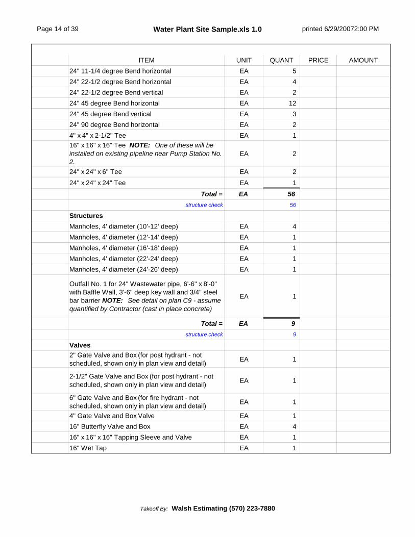
ITEM UNIT QUANT PRICE AMOUNT24" 11-1/4 degree Bend horizontal EA 524" 22-1/2 degree Bend horizontal EA 424" 22-1/2 degree Bend vertical EA 224" 45 degree Bend horizontal EA 1224" 45 degree Bend vertical EA 324" 90 degree Bend horizontal EA 24" x 4" x 2-1/2" Tee EA 116" x 16" x 16" Tee NOTE: One of these will beinstalled on existing pipeline near Pump Station No.2.
EA 2
24" x 24" x 6" Tee EA 224" x 24" x 24" Tee EA 1
Total = EA 56structure check 56
StructuresManholes, 4' diameter (10'-12' deep) EA 4Manholes, 4' diameter (12'-14' deep) EA 1Manholes, 4' diameter (16'-18' deep) EA 1Manholes, 4' diameter (22'-24' deep) EA 1Manholes, 4' diameter (24'-26' deep) EA 1
Outfall No. 1 for 24" Wastewater pipe, 6'-6" x 8'-0"with Baffle Wall, 3'-6" deep key wall and 3/4" steelbar barrier NOTE: See detail on plan C9 - assumequantified by Contractor (cast in place concrete)
EA 1
Total = EA 9structure check 9
Valves2" Gate Valve and Box (for post hydrant - notscheduled, shown only in plan view and detail) EA 1
2-1/2" Gate Valve and Box (for post hydrant - notscheduled, shown only in plan view and detail) EA 1
6" Gate Valve and Box (for fire hydrant - notscheduled, shown only in plan view and detail) EA 1
4" Gate Valve and Box Valve EA 116" Butterfly Valve and Box EA 416" x 16" x 16" Tapping Sleeve and Valve EA 116" Wet Tap EA 1
Takeoff By: Walsh Estimating (570) 223-7880

Page 15 of 39 Water Plant Site Sample.xls 1.0 printed 6/29/20072:00 PM
ITEM UNIT QUANT PRICE AMOUNTHydrantsPost Hydrants with 2" Nozzle EA 1Post Hydrants with 2-1/2" Nozzle EA 1Fire Hydrants EA 1Cut and Cap Existing 16" Pump Station No. 2Effluent LineShut Down and Drain existing 16" raw water line asneeded LS 1
Cut existing 16" DIP main NOTE: One location isat tee and one is 25'+/- from the tee toward SpringCreek
EA 2
Install short spool into bell end of existing main, capwith 16" cap, clamp with 4 3/4" tie rods andconcrete encase cap and stub
LS 1
Remove 16" DIP if required (assume 10'+/- deep) LF 25
Cut Existing 16" Raw Water Main to install NewConnections at Raw Water Pump Station No. 2
NOTE: Fittings are included in the abovetabulation.Shut Down and Drain existing 16" raw water line asneeded LS 1
Cut existing 16" DIP main EA 2Remove 16" DIP (assume 10'+/- deep) LF 20Water Supply Meter Manhole4'-0" diameter x 7'-0" deep Precast Concrete withflat slab top, Neenah R-1916-D manhole frame withbolted and gasketed cover and 4" concrete fillsloped to sump
EA 1
4" Flanged Adapter with anchor studs EA 24" Turbine Meter EA 1
Takeoff By: Walsh Estimating (570) 223-7880

Page 16 of 39 Water Plant Site Sample.xls 1.0 printed 6/29/20072:00 PM
ITEM UNIT QUANT PRICE AMOUNTRaw Water Meter Chamber8'-0" x 14'-0" I.D. x 8'-0" deep Precast Concretevault with steps and flat slab top for H20 loading, 3'-0" x 3'-0" Bilco J-4AL Double Door Access Hatchand 3" minimum concrete fill sloped to sump, set on12" stone base
EA 1
Precast Blockout, 26"+/- x 36"+/- in concretechamber for 4" chemical feed containment lines EA 1
Precast Blockout, 26"+/- x 46"+/- in concretechamber for 4" chemical feed containment lines EA 1
Concrete Fill and Modular Wall Seal for 4" pipe EA 12Concrete Fill and Modular Wall Seal for 6" pipe EA 21-1/2" Insulation on upper portion of interior wallsand ceiling SF 288
6" PVC Vent Riser set 2'-0" above ground with SSInsect Screen EA 1
High Level Probe for sump pump EA 1Raw Water Flow Transmitter EA 1Blended Raw Water Sample Pump EA 1Chemical Feed connections, drilled and tapped into24" pipe EA 6
Chemical Feed line supports EA 62" Combination air vacuum/release valve, drilledand tapped into 24" pipe EA 1
Chemical Containment Pipe End Assembly,consisting of 4" pipe flange, 4" blind flange tappedfor 1/4" plug and 1" IPS Appleton Liquid CordConnector
EA 12
Chemical Containment Pipe End Assembly,consisting of 6" pipe flange, 6" blind flange tappedfor 1/4" plug and 1" IPS Appleton Liquid CordConnector
EA 2
24" Raw Water Flow Meter EA 124" Flanged Adapter with anchor studs EA 1
Spool Piece, 24" diameter x 7'-0" long, PE x flange EA 1
Spool Piece, 24" diameter x 3'-6" long, PE x flange EA 2
Concrete Support block for 24" pipe EA 1Modular Wall Seal for 24" pipe EA 2Î Î
Subtotal
Takeoff By: Walsh Estimating (570) 223-7880
Page 17 of 39 Water Plant Site Sample.xls 1.0 printed 6/29/20072:00 PM
ITEM UNIT QUANT PRICE AMOUNT
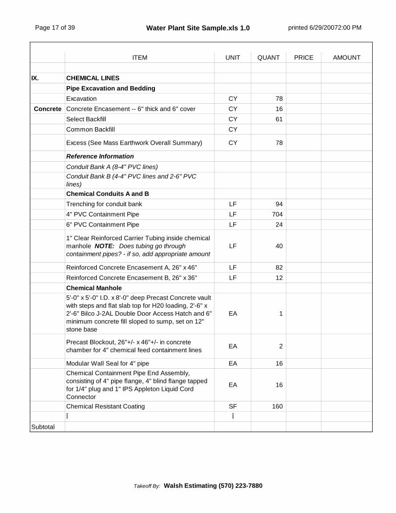
IX. CHEMICAL LINESPipe Excavation and BeddingExcavation CY 78
Concrete Concrete Encasement -- 6" thick and 6" cover CY 16Select Backfill CY 61Common Backfill CY
Excess (See Mass Earthwork Overall Summary) CY 78
Reference InformationConduit Bank A (8-4" PVC lines)Conduit Bank B (4-4" PVC lines and 2-6" PVClines)Chemical Conduits A and BTrenching for conduit bank LF 944" PVC Containment Pipe LF 7046" PVC Containment Pipe LF 24
1" Clear Reinforced Carrier Tubing inside chemicalmanhole NOTE: Does tubing go throughcontainment pipes? - if so, add appropriate amount
LF 40
Reinforced Concrete Encasement A, 26" x 46" LF 82Reinforced Concrete Encasement B, 26" x 36" LF 12Chemical Manhole5'-0" x 5'-0" I.D. x 8'-0" deep Precast Concrete vaultwith steps and flat slab top for H20 loading, 2'-6" x2'-6" Bilco J-2AL Double Door Access Hatch and 6"minimum concrete fill sloped to sump, set on 12"stone base
EA 1
Precast Blockout, 26"+/- x 46"+/- in concretechamber for 4" chemical feed containment lines EA 2
Modular Wall Seal for 4" pipe EA 16Chemical Containment Pipe End Assembly,consisting of 4" pipe flange, 4" blind flange tappedfor 1/4" plug and 1" IPS Appleton Liquid CordConnector
EA 16
Chemical Resistant Coating SF 160Î Î
Subtotal
Takeoff By: Walsh Estimating (570) 223-7880

Page 18 of 39 Water Plant Site Sample.xls 1.0 printed 6/29/20072:00 PM
ITEM UNIT QUANT PRICE AMOUNT
X. STORM SYSTEMNOTE: Downspout connection count has not beenincluded - unable to locate on plan.Pipe Excavation and BeddingExcavation CY 620Bedding -- Assume 6" thick and 12" cover CY 2802RC Select Backfill in pavement areas CY 80Common Backfill CY 210
Excess (See Mass Earthwork Overall Summary) CY 410
Pipe6" PVC (0'-4' deep) LF 7712" HDPE in pavement (0'-4' deep) LF 9312" HDPE (4'-6' deep) LF 16112" HDPE in pavement (6'-8' deep) LF 8012" HDPE (6'-8' deep) LF 1315" HDPE in pavement (0'-4' deep) LF 6015" HDPE (0'-4' deep) LF 4515" HDPE (4'-6' deep) LF 14618" RCP in pavement (0'-4' deep) LF 4818" HDPE in pavement (0'-4' deep) LF 2518" HDPE (0'-4' deep) LF 16218" HDPE (4'-6' deep) LF 100
Total = LF 1,010pipe check 1,010
StructuresEnd Section for Temporary 15" HDPE at SecondStreet entrance EA 1
End Section for 15" HDPE EA 1End Section for 18" HDPE EA 2
6" Cleanout Assembly with Neenah H20 Cast IronFrame and Cover set on concrete slab, 6" thick EA 1
2'-6" x 4'-0" Inlet with Neenah R-3401 Frame andGrate (0'-4' deep), 3" minimum concrete fill EA 5
Takeoff By: Walsh Estimating (570) 223-7880

Page 19 of 39 Water Plant Site Sample.xls 1.0 printed 6/29/20072:00 PM
ITEM UNIT QUANT PRICE AMOUNT
2'-6" x 4'-0" Inlet with Neenah R-3401 Frame andGrate (4'-6' deep including 3'-0" sump required foroil debris hood), 3" minimum concrete fill
EA 2
2'-6" x 4'-0" Inlet with Neenah R-3401 Frame andGrate (4'-6' deep), 3" minimum concrete fill EA 2
2'-6" x 4'-0" Inlet with Neenah R-3401 Frame andGrate (6'-8' deep), 3" minimum concrete fill EA 2
6" PVC Downspout Connection Assembly with (2)45 degree Bends and PVC Boot Cleanout "T"Branch
EA
Manholes, 4' diameter (3' deep) EA 1Manholes, 4' diameter (15' deep) EA 1
Outlet Structure, 2'-6" x 5'-0" x 6'+/- deep with 3"minimum concrete fill, 2'-0" x 6'-0" x 1/4" steelorifice plate and watertight vault lid with handle
EA 1
Total = EA 19structure check 19
Oil Debris HoodPlastic Composite Oil Debris Hood for 15" pipe EA 1Plastic Composite Oil Debris Hood for 18" pipe EA 1Trench DrainConcrete Flow Chamber, 4'-0" wide I.D., sloped 4'-6" to 5'-6" deep with 8" walls LF 48
Neenah Frame and Grate, R-4990-OX (Type A) LF 48Chemical Resistant Coating SF 712Spill Containment Chamber4'-0" x 4'-0" I.D. x 7'-0" deep Precast Concrete vaultwith steps and flat slab top for H20 loading, 2'-6" x2'-6" Bilco J-2AL Double Door Access Hatch and 3"minimum concrete fill sloped to sump, set on 12"stone base
EA 1
Precast or Core Bore concrete chamber for (2) 1/4"copper air lines EA 1
Modular Wall Seal for 2-1/4" pipe EA 1Precast or Core Bore concrete chamber for 6" PVCline EA 1
Modular Wall Seal for 6" pipe EA 16" PVC Ball Valve (Pneumatic operated) withControl Panel EA 1
Double 1/4" Copper Air Line LF 190
Takeoff By: Walsh Estimating (570) 223-7880
Page 20 of 39 Water Plant Site Sample.xls 1.0 printed 6/29/20072:00 PM
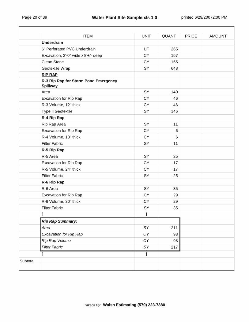
ITEM UNIT QUANT PRICE AMOUNTUnderdrain6" Perforated PVC Underdrain LF 265Excavation, 2'-0" wide x 8'+/- deep CY 157Clean Stone CY 155Geotextile Wrap SY 648RIP RAPR-3 Rip Rap for Storm Pond EmergencySpillwayArea SY 140Excavation for Rip Rap CY 46R-3 Volume, 12" thick CY 46Type II Geotextile SY 146R-4 Rip RapRip Rap Area SY 11Excavation for Rip Rap CY 6R-4 Volume, 18" thick CY 6Filter Fabric SY 11R-5 Rip RapR-5 Area SY 25Excavation for Rip Rap CY 17R-5 Volume, 24" thick CY 17Filter Fabric SY 25R-6 Rip RapR-6 Area SY 35Excavation for Rip Rap CY 29R-6 Volume, 30" thick CY 29Filter Fabric SY 35Î Î
Rip Rap Summary:Area SY 211Excavation for Rip Rap CY 98Rip Rap Volume CY 98Filter Fabric SY 217Î ÎÎ Î
Subtotal
Takeoff By: Walsh Estimating (570) 223-7880

Page 21 of 39 Water Plant Site Sample.xls 1.0 printed 6/29/20072:01 PM
ITEM UNIT QUANT PRICE AMOUNTXI. CONCRETE
SidewalkReinforced Concrete, 4" thick with 6 x 6 W2.9 xW2.9 WWM SF 1,558
Stone Base, 4" thick SF 1,558Miscellaneous Pad Reference Information4'-0" x 10'-0" at carbon feed facility SF 408'-0" x 7'-7" at loading dock SF 617'-7" x 15'-0" at loading dock SF 1054'-0" x 4'-0" at loading dock SF 16
4'-0" x 4'-0" at north side of plant SF 16
Total = SF 238Miscellaneous PadsReinforced Concrete, 4" thick with 6 x 6 W2.9 xW2.9 WWM SF 238
Stone Base, 4" thick SF 238Transformer Pads - if required under thiscontractReinforced Concrete, 4" thick with 6 x 6 W2.9 xW2.9 WWM SF 98
Stone Base, 4" thick SF 98Meter Cabinet Pad - if required under thiscontractReinforced Concrete, 4" thick with 6 x 6 W2.9 xW2.9 WWM SF 36
Stone Base, 4" thick SF 36
Generator Pad - if required under this contract
Reinforced Concrete, assume 4" thick with 6 x 6W2.9 x W2.9 WWM SF 240
Stone Base, 4" thick SF 240Chiller Pad - if required under this contractReinforced Concrete, assume 4" thick with 6 x 6W2.9 x W2.9 WWM SF 40
Stone Base, 4" thick SF 40Concrete Paving at Trench DrainReinforced Concrete, 8" thick with 6 x 6 W2.9 xW2.9 WWM SF 1,216
Stone Base, 8" thick SF 1,216
Takeoff By: Walsh Estimating (570) 223-7880

Page 22 of 39 Water Plant Site Sample.xls 1.0 printed 6/29/20072:01 PM
ITEM UNIT QUANT PRICE AMOUNTDumpster PadReinforced Concrete, 8" thick with 6 x 6 W2.9 xW2.9 WWM SF 288
Stone Base, 8" thick SF 288Miscellaneous ConcretePrecast Wheel Stops EA 7Î Î
Subtotal
XII. PAVEMENTAccess RoadFine Grade and Compact Subgrade SY 3,6792A Stone Base Course, 8" thick SY 3,679Bituminous Concrete Base Course, 4" thick SY 3,679ID-2 Bituminous Wearing Course, 2" thick SY 3,679Road AFine Grade and Compact Subgrade SY 6392A Stone Base Course, 6" thick SY 639Bituminous Concrete Base Course, 4" thick SY 639ID-2 Bituminous Wearing Course, 2" thick SY 639Type 1I Shoulder UpgradeSaw Cut existing pavement and Seal Joint LF 800Fine Grade and Compact Subgrade SY 7112A Stone Base Course, 6" thick SY 711Bituminous Concrete Base Course, 4" thick SY 711ID-3 Bituminous Wearing Course, 1-1/2" thick SY 7114" Pavement Base Drain LF 8004" Pavement Base Drain Outlet LF 105Î Î
Subtotal
Takeoff By: Walsh Estimating (570) 223-7880

Page 23 of 39 Water Plant Site Sample.xls 1.0 printed 6/29/20072:01 PM
ITEM UNIT QUANT PRICE AMOUNTXIII. PAVING REMOVAL AND REPLACEMENT FOR UTILITIES
Temporary PavementInstall and Remove Temporary Paving, 2" thick SY 780Roosevelt Street and Type 6 ShoulderSaw Cut Pavement, full depth LF 140Saw Cut Pavement, trim back LF 140Pavement Removal, Assume 40' wide SY 310Fine Grade and Compact Subgrade SY 310Bituminous Concrete Base Course, 4" thick SY 310ID-2 Bituminous Wearing Course, 1-1/2" thick SY 310Driveway PavementSaw Cut Pavement, full depth LF 52Saw Cut Pavement, trim back LF 52Pavement Removal, 20' width at SecondStreet/Roosevelt intersection and assume fullreplacement from westerly limit pipe crossing to endat water plant pump station
SY 470
Fine Grade and Compact Subgrade SY 470Bituminous Concrete Base Course, 4" thick SY 470ID-2 Bituminous Wearing Course, 1-1/2" thick SY 470Gravel Driveway at Lehigh River SiteFine Grade and Compact Subgrade SY 6002A Stone Base Course, 5" thick SY 600Î Î
Subtotal
XIV. STRIPING AND SIGNSStripingStriping Parking Spaces EA 7Striping Crosshatch Area (including lines andspaces) SF 144
Striping Handicap Logo EA 1
Takeoff By: Walsh Estimating (570) 223-7880
Page 24 of 39 Water Plant Site Sample.xls 1.0 printed 6/29/20072:01 PM
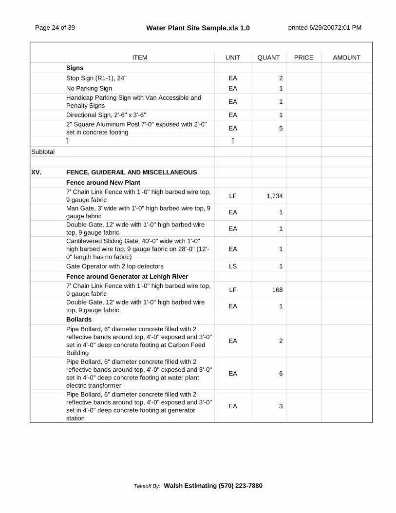
ITEM UNIT QUANT PRICE AMOUNTSignsStop Sign (R1-1), 24" EA 2No Parking Sign EA 1Handicap Parking Sign with Van Accessible andPenalty Signs EA 1
Directional Sign, 2'-6" x 3'-6" EA 12" Square Aluminum Post 7'-0" exposed with 2'-6"set in concrete footing EA 5
Î ÎSubtotal
XV. FENCE, GUIDERAIL AND MISCELLANEOUSFence around New Plant7' Chain Link Fence with 1'-0" high barbed wire top,9 gauge fabric LF 1,734
Man Gate, 3' wide with 1'-0" high barbed wire top, 9gauge fabric EA 1
Double Gate, 12' wide with 1'-0" high barbed wiretop, 9 gauge fabric EA 1
Cantilevered Sliding Gate, 40'-0" wide with 1'-0"high barbed wire top, 9 gauge fabric on 28'-0" (12'-0" length has no fabric)
EA 1
Gate Operator with 2 lop detectors LS 1Fence around Generator at Lehigh River7' Chain Link Fence with 1'-0" high barbed wire top,9 gauge fabric LF 168
Double Gate, 12' wide with 1'-0" high barbed wiretop, 9 gauge fabric EA 1
BollardsPipe Bollard, 6" diameter concrete filled with 2reflective bands around top, 4'-0" exposed and 3'-0"set in 4'-0" deep concrete footing at Carbon FeedBuilding
EA 2
Pipe Bollard, 6" diameter concrete filled with 2reflective bands around top, 4'-0" exposed and 3'-0"set in 4'-0" deep concrete footing at water plantelectric transformer
EA 6
Pipe Bollard, 6" diameter concrete filled with 2reflective bands around top, 4'-0" exposed and 3'-0"set in 4'-0" deep concrete footing at generatorstation
EA 3
Takeoff By: Walsh Estimating (570) 223-7880
Page 25 of 39 Water Plant Site Sample.xls 1.0 printed 6/29/20072:01 PM
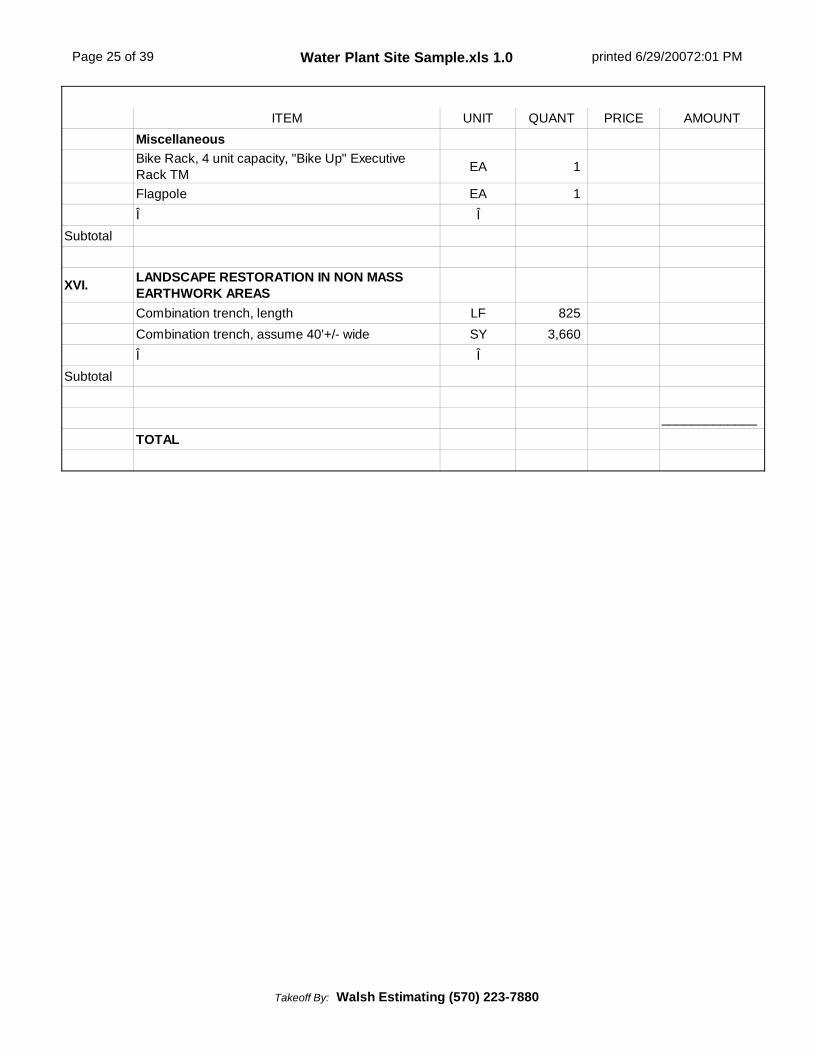
ITEM UNIT QUANT PRICE AMOUNTMiscellaneousBike Rack, 4 unit capacity, "Bike Up" ExecutiveRack TM EA 1
Flagpole EA 1Î Î
Subtotal
XVI. LANDSCAPE RESTORATION IN NON MASSEARTHWORK AREASCombination trench, length LF 825Combination trench, assume 40'+/- wide SY 3,660Î Î
Subtotal
_____________TOTAL
Takeoff By: Walsh Estimating (570) 223-7880

Page 26 of 39 Water Plant Site Sample.xls Earth Summary 1.0 print date: 6/29/2007 2:04 PM
Takeoff by: T. O'Neill
Summary by: R. Decker
Checked by: R. Decker
Date: 5/25/2007
Agtek File: WTP Mass 1.0, WTP SDtr EX 1.1, WTP Fnl 1.1 (See Note 1)
DISTURBANCE AREA & STRIPPING RAW CUT & FILL VOLUMES
Subgrade Cut, Surface Fill, Surface Total Area 6" Strip Cut Earth Cut Rock
SF SF SF Acres BCY BCY BCY
ALL AREAS
Basin and Swale 0.50' 21,933 30,882 52,815 1.21 978 2,414 0
Pavement Areas 1.17' 35,750 6,321 42,071 0.97 779 7,468 736Mass grade landscape andslope areas, excluding plantfootprint
0.50' 44,196 10,488 54,684 1.26 1,013 12,053 799
Structure Excavation with 4'-6'clearance and 1H:1V slopes var. 48,143 0 48,143 1.11 892 31,921 5,815
Structure Backfill interior (820cy is deep tank laybackbackfill, balance is laybackunder admin section ofbuilding and 3'+/- average fillunder slab)
var. 0 17,627 17,627 0.40 326 0 0
Structure Backfill exteriorunder landscape 0.00' 0 25,610 25,610 0.59 474 0 0
Final grade around plant,landscape areas 0.50' 10,082 35,925 46,007 1.06 852 1,368 0
Final grade around plant,pavement areas 1.17' 0 13,300 13,300 0.31 246 0 0
adjust for overlapping area 0 0 (300,257) (6.89) (5,560) 0 0
Disturbance Area 0 0 224,913 5.16 4,165 0 0
Î. 0 0 0 0.00 0 0 0
__________ __________ __________ __________ __________ __________ ___________
TOTALS 160,104 140,153 224,913 5.18 4,165 55,224 7,350
NOTES: Total Excess1 TOPSOIL volumes are NOT included in the RAW and ADJUSTED cut & fill volumes. All earth volumes are calculated, after stripping and to proposed subgrade.
Redistribute Topsoil, 6'' thick 0 SY • Topsoil Required 6" 0 BCY • Excess (Borrow) Topsoil 4,165 BCY
2 The last column shows the approximate finish grade adjustment required to achieve a balanced site.
3 Pavement areas above are not to be used for exact pavement areas -- e.g. islands are sometimes included within pavement earthwork areas.
Water Plantplan dated 12/2003
Takeoff By: Walsh Estimating (570) 223-7880
Page 27 of 39 Water Plant Site Sample.xls Earth Summary 1.0 print date: 6/29/2007 2:04 PM
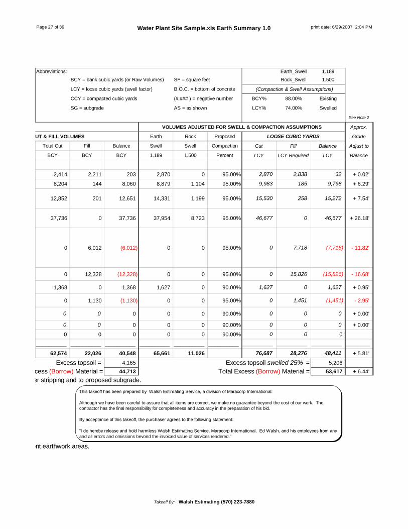
Abbreviations: Earth_Swell 1.189BCY = bank cubic yards (or Raw Volumes) SF = square feet Rock_Swell 1.500
LCY = loose cubic yards (swell factor) B.O.C. = bottom of concrete (Compaction & Swell Assumptions)
CCY = compacted cubic yards (#,### ) = negative number BCY% 88.00% Existing
SG = subgrade AS = as shown LCY% 74.00% Swelled
See Note 2
VOLUMES ADJUSTED FOR SWELL & COMPACTION ASSUMPTIONS Approx.
RAW CUT & FILL VOLUMES Earth Rock Proposed LOOSE CUBIC YARDS Grade
Total Cut Fill Balance Swell Swell Compaction Cut Fill Balance Adjust to
BCY BCY BCY 1.189 1.500 Percent LCY LCY Required LCY Balance
2,414 2,211 203 2,870 0 95.00% 2,870 2,838 32 + 0.02'
8,204 144 8,060 8,879 1,104 95.00% 9,983 185 9,798 + 6.29'
12,852 201 12,651 14,331 1,199 95.00% 15,530 258 15,272 + 7.54'
37,736 0 37,736 37,954 8,723 95.00% 46,677 0 46,677 + 26.18'
0 6,012 (6,012) 0 0 95.00% 0 7,718 (7,718) - 11.82'
0 12,328 (12,328) 0 0 95.00% 0 15,826 (15,826) - 16.68'
1,368 0 1,368 1,627 0 90.00% 1,627 0 1,627 + 0.95'
0 1,130 (1,130) 0 0 95.00% 0 1,451 (1,451) - 2.95'
0 0 0 0 0 90.00% 0 0 0 + 0.00'
0 0 0 0 0 90.00% 0 0 0 + 0.00'
0 0 0 0 0 90.00% 0 0 0
__________ __________ __________ __________ __________ __________ __________ __________ __________ ________
62,574 22,026 40,548 65,661 11,026 76,687 28,276 48,411 + 5.81'
Excess topsoil = 4,165 Excess topsoil swelled 25% = 5,206Total Excess (Borrow) Material = 44,713 Total Excess (Borrow) Material = 53,617 + 6.44'
TOPSOIL volumes are NOT included in the RAW and ADJUSTED cut & fill volumes. All earth volumes are calculated, after stripping and to proposed subgrade.
Pavement areas above are not to be used for exact pavement areas -- e.g. islands are sometimes included within pavement earthwork areas.
This takeoff has been prepared by Walsh Estimating Service, a division of Maracorp International:
Although we have been careful to assure that all items are correct, we make no guarantee beyond the cost of our work. Thecontractor has the final responsibility for completeness and accuracy in the preparation of his bid.
By acceptance of this takeoff, the purchaser agrees to the following statement:
“I do hereby release and hold harmless Walsh Estimating Service, Maracorp International, Ed Walsh, and his employees from anyand all errors and omissions beyond the invoiced value of services rendered.”
Takeoff By: Walsh Estimating (570) 223-7880

Page 28 of 39 Water Plant Site Sample.xls Pipe Excav Worksheet 1.0 printed: 6/29/2007 2:06 PM
INPUTS EXCAVATION BEDDING BACKFILL
Water Treatment Plant Length AvgDepth Pipe Dia
TrenchLimits
per side
TrenchWidth
ExcavateVolume
UnderPipe
% pipecover cover Bed Vol Pipe
VolSelectBackfill
Com'nB'fill Excess
Sample LF FT IN IN FT CY IN % IN CY CY CY CY CYPrepared: 5/25/2007
I. SANITARY SEWER PIPE EXCAVATIONServices4" PVC Lateral in pavement (0'-4' deep) 210 4.0 4'' 12.0'' 2.33 72 6'' 100% 12'' 33 1 38 0 72
PipeNOTE: Install sewer force mainprior to installation of remainingwater pipelines.4" restrained joint DIP ForceMain (6'-8' deep) 50 8.0 4'' 12.0'' 2.33 35 6'' 100% 12'' 8 0 0 27 8
6" restrained joint DIP ForceMain (6'-8' deep) 300 8.0 6'' 12.0'' 2.50 222 6'' 100% 12'' 53 2 0 167 55
6" restrained joint DIP ForceMain down stream banks (6'-8'deep)
45 8.0 6'' 12.0'' 2.50 33 6'' 100% 12'' 8 0 0 25 8
6" restrained joint DIP ForceMain in existing paved driveway(6'-8' deep)
12 8.0 6'' 12.0'' 2.50 9 6'' 100% 12'' 2 0 7 0 9
This takeoff has been prepared by Walsh Estimating Service , a division of Maracorp International:
Although we have been careful to assure that all items are correct, we make no guarantee beyond the cost ofour work. The contractor has the final responsibility for completeness and accuracy in the preparation of hisbid.
By acceptance of this takeoff, the purchaser agrees to the following statement:
"I do hereby release and hold harmless Walsh Estimating Service, Maracorp International, Ed Walsh, and hisemployees from any and all errors and omissions beyond the invoiced value of services rendered."
Takeoff By: Walsh Estimating (570) 223-7880

Page 29 of 39 Water Plant Site Sample.xls Pipe Excav Worksheet 1.0 printed: 6/29/2007 2:06 PM
INPUTS EXCAVATION BEDDING BACKFILL
Water Treatment Plant Length AvgDepth Pipe Dia
TrenchLimits
per side
TrenchWidth
ExcavateVolume
UnderPipe
% pipecover cover Bed Vol Pipe
VolSelectBackfill
Com'nB'fill Excess
Sample LF FT IN IN FT CY IN % IN CY CY CY CY CY6" restrained joint DIP ForceMain in Spring Creek (6'-8'deep)
15 8.0 6'' 12.0'' 2.50 11 6'' 100% 12'' 3 0 8 0 11
6" restrained joint DIP ForceMain (8'-10' deep) 110 10.0 6'' 18.0'' 3.50 143 6'' 100% 12'' 28 1 0 114 29
6" restrained joint DIP ForceMain (10'-12' deep) 478 12.0 6'' 18.0'' 3.50 744 6'' 100% 12'' 120 3 0 621 123
6" restrained joint DIP ForceMain in Roosevelt Streetpavement (12'-14' deep)
75 14.0 6'' 18.0'' 3.50 136 6'' 100% 12'' 19 1 116 0 136
6" restrained joint DIP ForceMain (14'-16' deep) 100 16.0 6'' 18.0'' 3.50 207 6'' 100% 12'' 25 1 0 181 26
6" restrained joint DIP ForceMain in pavement (12'-14' deep) 75 14.0 6'' 18.0'' 3.50 136 6'' 100% 12'' 19 1 116 0 136
Î 0 0.0 0'' 12.0'' 2.00 0 6'' 100% 12'' 0 0 0 0 0__________________________ _____ _______ ______ ______ ______ _____ ______Excavation 1748 CY 1748 318 10 285 1135 613Bedding 318 CYSelect Backfill 285 CYCommon Backfill 1135 CYExcess 613 CY
Takeoff By: Walsh Estimating (570) 223-7880

Page 30 of 39 Water Plant Site Sample.xls Pipe Excav Worksheet 1.0 printed: 6/29/2007 2:06 PM
INPUTS EXCAVATION BEDDING BACKFILL
Water Treatment Plant Length AvgDepth Pipe Dia
TrenchLimits
per side
TrenchWidth
ExcavateVolume
UnderPipe
% pipecover cover Bed Vol Pipe
VolSelectBackfill
Com'nB'fill Excess
Sample LF FT IN IN FT CY IN % IN CY CY CY CY CYII. WATER PIPE EXCAVATION
Plant Service Water2" Service Water, assumecopper (4'-6' deep) 85 6.0 2'' 12.0'' 2.17 41 6'' 100% 12'' 11 0 0 30 11
4" restrained joint DIP inpavement (4'-6' deep) 65 6.0 4'' 12.0'' 2.33 34 6'' 100% 12'' 10 0 24 0 34
Water Supply2-1/2" restrained joint DIP (6'-8'deep) 50 8.0 2'' 12.0'' 2.17 32 6'' 100% 12'' 7 0 0 25 7
4" restrained joint DIP (6'-8'deep) 35 8.0 4'' 12.0'' 2.33 24 6'' 100% 12'' 5 0 0 19 5
4" restrained joint DIP in existinggravel driveway (6'-8' deep) 170 8.0 4'' 12.0'' 2.33 117 6'' 100% 12'' 26 1 90 0 117
4" restrained joint DIP in existingpaved driveway (6'-8' deep) 211 8.0 4'' 12.0'' 2.33 146 6'' 100% 12'' 33 1 112 0 146
4" DIP Drain (6'-8' deep) 45 8.0 4'' 12.0'' 2.33 31 6'' 100% 12'' 7 0 0 24 7Raw Water Pipe16" restrained joint DIP inexisting paved driveway (0'-6'deep)
37 6.0 16'' 12.0'' 3.33 27 6'' 100% 12'' 11 2 14 0 27
24" restrained joint DIP (0'-6'deep) 75 6.0 24'' 12.0'' 4.00 67 6'' 100% 12'' 30 9 0 28 39
24" restrained joint DIP (6'-8'deep) 360 8.0 24'' 12.0'' 4.00 427 6'' 100% 12'' 145 42 0 240 187
Takeoff By: Walsh Estimating (570) 223-7880
Page 31 of 39 Water Plant Site Sample.xls Pipe Excav Worksheet 1.0 printed: 6/29/2007 2:06 PM
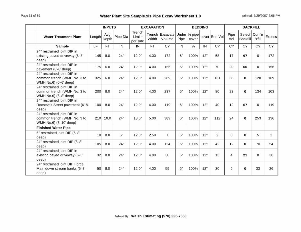
INPUTS EXCAVATION BEDDING BACKFILL
Water Treatment Plant Length AvgDepth Pipe Dia
TrenchLimits
per side
TrenchWidth
ExcavateVolume
UnderPipe
% pipecover cover Bed Vol Pipe
VolSelectBackfill
Com'nB'fill Excess
Sample LF FT IN IN FT CY IN % IN CY CY CY CY CY24" restrained joint DIP inexisting paved driveway (6'-8'deep)
145 8.0 24'' 12.0'' 4.00 172 6'' 100% 12'' 58 17 97 0 172
24" restrained joint DIP inpavement (0'-6' deep) 175 6.0 24'' 12.0'' 4.00 156 6'' 100% 12'' 70 20 66 0 156
24" restrained joint DIP incommon trench (WMH No. 3 toWMH No.6) (0'-6' deep)
325 6.0 24'' 12.0'' 4.00 289 6'' 100% 12'' 131 38 0 120 169
24" restrained joint DIP incommon trench (WMH No. 3 toWMH No.6) (6'-8' deep)
200 8.0 24'' 12.0'' 4.00 237 6'' 100% 12'' 80 23 0 134 103
24" restrained joint DIP inRoosevelt Street pavement (6'-8'deep)
100 8.0 24'' 12.0'' 4.00 119 6'' 100% 12'' 40 12 67 0 119
24" restrained joint DIP incommon trench (WMH No. 3 toWMH No.6) (8'-10' deep)
210 10.0 24'' 18.0'' 5.00 389 6'' 100% 12'' 112 24 0 253 136
Finished Water Pipe6" restrained joint DIP (6'-8'deep) 10 8.0 6'' 12.0'' 2.50 7 6'' 100% 12'' 2 0 0 5 2
24" restrained joint DIP (6'-8'deep) 105 8.0 24'' 12.0'' 4.00 124 6'' 100% 12'' 42 12 0 70 54
24" restrained joint DIP inexisting paved driveway (6'-8'deep)
32 8.0 24'' 12.0'' 4.00 38 6'' 100% 12'' 13 4 21 0 38
24" restrained joint DIP ForceMain down stream banks (6'-8'deep)
50 8.0 24'' 12.0'' 4.00 59 6'' 100% 12'' 20 6 0 33 26
Takeoff By: Walsh Estimating (570) 223-7880

Page 32 of 39 Water Plant Site Sample.xls Pipe Excav Worksheet 1.0 printed: 6/29/2007 2:06 PM
INPUTS EXCAVATION BEDDING BACKFILL
Water Treatment Plant Length AvgDepth Pipe Dia
TrenchLimits
per side
TrenchWidth
ExcavateVolume
UnderPipe
% pipecover cover Bed Vol Pipe
VolSelectBackfill
Com'nB'fill Excess
Sample LF FT IN IN FT CY IN % IN CY CY CY CY CY24" restrained joint DIP ForceMain in Spring Creek (6'-8'deep)
15 8.0 24'' 12.0'' 4.00 18 6'' 100% 12'' 6 2 10 0 18
24" restrained joint DIP (8'-10'deep) 58 10.0 24'' 18.0'' 5.00 107 6'' 100% 12'' 31 7 0 69 38
24" restrained joint DIP (12'-14'deep) 42 14.0 24'' 18.0'' 5.00 109 6'' 100% 12'' 22 5 0 82 27
24" restrained joint DIP inpavement (0'-6' deep) 70 6.0 24'' 12.0'' 4.00 62 6'' 100% 12'' 28 8 26 0 62
24" restrained joint DIP inpavement (12'-14' deep) 35 14.0 24'' 18.0'' 5.00 91 6'' 100% 12'' 19 4 68 0 91
24" restrained joint DIP incommon trench (WMH No. 3 toWMH No.6) (0'-6' deep)
145 6.0 24'' 12.0'' 4.00 129 6'' 100% 12'' 58 17 0 54 75
24" restrained joint DIP incommon trench (WMH No. 3 toWMH No.6) (6'-8' deep)
265 8.0 24'' 12.0'' 4.00 314 6'' 100% 12'' 107 31 0 176 138
24" restrained joint DIP incommon trench in RooseveltStreet (WMH No. 3 to WMHNo.6) (6'-8' deep)
60 8.0 24'' 12.0'' 4.00 71 6'' 100% 12'' 24 7 0 40 31
24" restrained joint DIP incommon trench (WMH No. 3 toWMH No.6) (8'-10' deep)
260 10.0 24'' 18.0'' 5.00 481 6'' 100% 12'' 138 30 0 313 168
24" restrained joint DIP incommon trench (WMH No. 3 toWMH No.6) (10'-12' deep)
65 12.0 24'' 18.0'' 5.00 144 6'' 100% 12'' 35 8 0 101 43
Takeoff By: Walsh Estimating (570) 223-7880

Page 33 of 39 Water Plant Site Sample.xls Pipe Excav Worksheet 1.0 printed: 6/29/2007 2:06 PM
INPUTS EXCAVATION BEDDING BACKFILL
Water Treatment Plant Length AvgDepth Pipe Dia
TrenchLimits
per side
TrenchWidth
ExcavateVolume
UnderPipe
% pipecover cover Bed Vol Pipe
VolSelectBackfill
Com'nB'fill Excess
Sample LF FT IN IN FT CY IN % IN CY CY CY CY CYWastewater Pipe 0.024" restrained joint DIP (0'-6'deep) 38 6.0 24'' 12.0'' 4.00 34 6'' 100% 12'' 15 4 0 15 19
24" restrained joint DIP inexisting paved driveway (0'-6'deep)
12 6.0 24'' 12.0'' 4.00 11 6'' 100% 12'' 5 1 5 0 11
24" restrained joint DIP (16'-18'deep) 65 18.0 24'' 18.0'' 5.00 217 6'' 100% 12'' 35 8 0 174 43
24" restrained joint DIP (20'-22'deep) 65 22.0 24'' 18.0'' 5.00 265 6'' 100% 12'' 35 8 0 222 43
24" restrained joint DIP (24'-26'deep) 40 26.0 24'' 18.0'' 5.00 193 6'' 100% 12'' 21 5 0 167 26
24" restrained joint DIP inpavement (18'-20' deep) 140 20.0 24'' 18.0'' 5.00 519 6'' 100% 12'' 74 16 429 0 519
24" restrained joint DIP incommon trench in existingpaved driveway (WMH No. 3 toWMH No.6) (8'-10' deep)
40 10.0 24'' 18.0'' 5.00 74 6'' 100% 12'' 21 5 48 0 74
24" restrained joint DIP incommon trench (WMH No. 3 toWMH No.6) (8'-10' deep)
340 10.0 24'' 18.0'' 5.00 630 6'' 100% 12'' 181 40 0 409 221
24" restrained joint DIP incommon trench (WMH No. 3 toWMH No.6) (10'-12' deep)
89 12.0 24'' 18.0'' 5.00 198 6'' 100% 12'' 47 10 0 141 57
24" restrained joint DIP incommon trench (WMH No. 3 toWMH No.6) (12'-14' deep)
103 14.0 24'' 18.0'' 5.00 267 6'' 100% 12'' 55 12 0 200 67
24" restrained joint DIP incommon trench in RooseveltStreet (WMH No. 3 to WMHNo.6) (12'-14' deep)
65 14.0 24'' 18.0'' 5.00 169 6'' 100% 12'' 35 8 126 0 169
Takeoff By: Walsh Estimating (570) 223-7880

Page 34 of 39 Water Plant Site Sample.xls Pipe Excav Worksheet 1.0 printed: 6/29/2007 2:06 PM
INPUTS EXCAVATION BEDDING BACKFILL
Water Treatment Plant Length AvgDepth Pipe Dia
TrenchLimits
per side
TrenchWidth
ExcavateVolume
UnderPipe
% pipecover cover Bed Vol Pipe
VolSelectBackfill
Com'nB'fill Excess
Sample LF FT IN IN FT CY IN % IN CY CY CY CY CY24" restrained joint DIP incommon trench (WMH No. 3 toWMH No.6) (14'-16' deep)
33 16.0 24'' 18.0'' 5.00 98 6'' 100% 12'' 18 4 0 76 22
24" restrained joint DIP incommon trench (WMH No. 3 toWMH No.6) (16'-18' deep)
33 18.0 24'' 18.0'' 5.00 110 6'' 100% 12'' 18 4 0 88 22
24" restrained joint DIP incommon trench (WMH No. 3 toWMH No.6) (18'-20' deep)
33 20.0 24'' 18.0'' 5.00 122 6'' 100% 12'' 18 4 0 100 22
24" restrained joint DIP incommon trench (WMH No. 3 toWMH No.6) (20' -22' deep)
33 22.0 24'' 18.0'' 5.00 134 6'' 100% 12'' 18 4 0 112 22
24" restrained joint DIP incommon trench (WMH No. 3 toWMH No.6) (22' 24' deep)
33 24.0 24'' 18.0'' 5.00 147 6'' 100% 12'' 18 4 0 125 22
24" restrained joint DIP incommon trench (WMH No. 3 toWMH No.6) (24'-26' deep)
33 26.0 24'' 18.0'' 5.00 159 6'' 100% 12'' 18 4 0 137 22
Î 0 0.0 0'' 12.0'' 2.00 0 6'' 100% 12'' 0 0 0 0 0__________________________ _____ _______ ______ ______ ______ _____ ______Excavation 7409 CY 7409 1953 471 1203 3782 3627Bedding 1953 CYSelect Backfill 1203 CYCommon Backfill 3782 CYExcess 3627 CY
Takeoff By: Walsh Estimating (570) 223-7880

Page 35 of 39 Water Plant Site Sample.xls Pipe Excav Worksheet 1.0 printed: 6/29/2007 2:06 PM
INPUTS EXCAVATION BEDDING BACKFILL
Water Treatment Plant Length AvgDepth Pipe Dia
TrenchLimits
per side
TrenchWidth
ExcavateVolume
UnderPipe
% pipecover cover Bed Vol Pipe
VolSelectBackfill
Com'nB'fill Excess
Sample LF FT IN IN FT CY IN % IN CY CY CY CY CYIII. STORM PIPE EXCAVATION
6" PVC (0'-4' deep) 77 4.0 6'' 12.0'' 2.50 29 6'' 100% 12'' 14 1 0 14 1512" HDPE in pavement (0'-4'deep) 93 4.0 12'' 12.0'' 3.00 41 6'' 100% 12'' 23 3 15 0 41
12" HDPE (4'-6' deep) 161 6.0 12'' 12.0'' 3.00 107 6'' 100% 12'' 40 5 0 62 4512" HDPE in pavement (6'-8'deep) 80 8.0 12'' 12.0'' 3.00 71 6'' 100% 12'' 20 2 49 0 71
12" HDPE (6'-8' deep) 13 8.0 12'' 12.0'' 3.00 12 6'' 100% 12'' 3 0 0 9 315" HDPE in pavement (0'-4'deep) 60 4.0 15'' 12.0'' 3.25 29 6'' 100% 12'' 17 3 9 0 29
15" HDPE (0'-4' deep) 45 4.0 15'' 12.0'' 3.25 22 6'' 100% 12'' 13 2 0 7 1515" HDPE (4'-6' deep) 146 6.0 15'' 12.0'' 3.25 105 6'' 100% 12'' 42 7 0 56 4918" RCP in pavement (0'-4'deep) 48 4.0 18'' 12.0'' 3.50 25 6'' 100% 12'' 16 3 6 0 25
18" HDPE in pavement (0'-4'deep) 25 4.0 18'' 12.0'' 3.50 13 6'' 100% 12'' 8 2 3 0 13
18" HDPE (0'-4' deep) 162 4.0 18'' 12.0'' 3.50 84 6'' 100% 12'' 52 11 0 21 6318" HDPE (4'-6' deep) 100 6.0 18'' 12.0'' 3.50 78 6'' 100% 12'' 32 7 0 39 39Î 0 0.0 0'' 12.0'' 2.00 0 6'' 100% 12'' 0 0 0 0 0__________________________ _____ _______ ______ ______ ______ _____ ______Excavation 616 CY 616 280 46 82 208 408Bedding 280 CYSelect Backfill 82 CYCommon Backfill 208 CYExcess 408 CY
Takeoff By: Walsh Estimating (570) 223-7880

Page 36 of 39 Water Plant Site Sample.xls Pipe Excav Worksheet 1.0 printed: 6/29/2007 2:08 PM
INPUTS EXCAVATION BEDDING BACKFILL
Water Treatment Plant Length AvgDepth Pipe Dia
TrenchLimits
per side
TrenchWidth
ExcavateVolume
UnderPipe
% pipecover cover Bed Vol Pipe
VolSelectBackfill
Com'nB'fill Excess
Sample LF FT IN IN FT CY IN % IN CY CY CY CY CYIV. CHEMICAL LINES
Reinforced ConcreteEncasement A, 26" x 46" 82 6.0 4'' 6.0'' 3.83 70 6'' 100% 6'' 14 1 55 0 70
Reinforced ConcreteEncasement B, 26" x 36" 12 6.0 4'' 6.0'' 3.00 8 6'' 100% 6'' 2 0 6 0 8
Î 0 0.0 0'' 12.0'' 2.00 0 6'' 100% 12'' 0 0 0 0 0__________________________ _____ _______ ______ ______ ______ _____ ______Excavation 78 CY 78 16 1 61 0 78Concrete 16 CYSelect Backfill 61 CYCommon Backfill 0 CYExcess 78 CY
Takeoff By: Walsh Estimating (570) 223-7880

Page 37 of 39 Water Plant Site Sample.xls Pave Worksheet 1.0 printed: 6/29/2007 2:49 PM
STATIONS TOTAL
Ref Description From To Length Width Radius Count Add Deduct AREA (SF)
Access Road Pavement:
p. 0 Access Road 0+00.00 0+80.00 80.00 24' r = 50' 2 0 0 2,995
p. 0 Access Road 0+80.00 1+60.00 80.00 26' r = 0' 0 0 0 2,080
p. 0 Access Road 1+60.00 2+13.00 53.00 24' r = 0' 0 0 0 1,272
p. 0 Access Road 2+13.00 2+70.00 57.00 26' r = 0' 0 0 0 1,482
p. 0 Access Road 2+70.00 7+11.00 441.00 24' r = 20' 1 0 0 10,670
p. 0 Access Road Parking 6+07.00 6+77.00 70.00 18' r = 10' 2 0 0 1,303
p. 0 Access Road Unloading Area 7+11.00 8+11.00 100.00 147' r = 0' 0 0 1,392 13,308
p. 0 0+00.00 0+00.00 0.00 0' r = 0' 0 0 0 0
______ ________________________ _______ _______ _______ _______ _______ _______ _______ _______ ___________
881.00 33,110
Road A Pavement:
p. 0 Road A 0+12.00 1+93.00 181.00 20' r = 30' 2 0 0 4,007
p. 0 Road A spur 0+10.00 0+78.00 68.00 20' r = 30' 2 0 0 1,747
______ ________________________ _______ _______ _______ _______ _______ _______ _______ _______ ___________
249.00 5,754
Takeoff By: Walsh Estimating (570) 223-7880

Page 38 of 39 Water Plant Site Sample.xls: Footing Excav 1.0 6/29/2007 2:51 PM
CONCRETE • CONCRETE • CONCRETE • CONCRETE • CONCRETE • CONCRETE • CONCRETE • CONCRETE • CONCRETE • CONCRETE • CONCRETE • CONCRETE • CONCRETE • CONCRETE •
DIMENSIONS EXCAVATION BACKFILL
REF DESCRIPTION SubgradeElev.
Top ofFooting Elev. Width Length Height Qty
Volume(CY) Depth Width
AddLength
AddFootinglength
Excav.(CY)
Wallthick.
FootingDeduct
WallDeduct
Backfill(CY)
Water Treatment Plant
Prepared: 5/25/2007This takeoff has been prepared by Walsh Estimating Service, a division of Maracorp International:
Although we have been careful to assure that all items are correct, we make no guarantee beyond the cost of ourwork. The contractor has the final responsibility for completeness and accuracy in the preparation of his bid.
By acceptance of this takeoff, the purchaser agrees to the following statement:
I do hereby release and hold harmless Walsh Estimating Service, Maracorp International, Ed Walsh, and hisemployees from any and all errors and omissions beyond the invoiced value of services rendered.
Takeoff By: Walsh Estimating (570) 223-7880

Page 39 of 39 Water Plant Site Sample.xls: Footing Excav 1.0 6/29/2007 2:51 PM
DIMENSIONS EXCAVATION BACKFILL
REF DESCRIPTION SubgradeElev.
Top ofFooting Elev. Width Length Height Qty
Volume(CY) Depth Width
AddLength
AddFootinglength
Excav.(CY)
Wallthick.
FootingDeduct
WallDeduct
Backfill(CY)
Carbon Feed Building
Footing for 6" slab 2.00 12.00 1.00 2 1.78 2.50 2.50 0.00 24.00 10.00 12.0'' (1.78) (1.33) 6.89
Footing for 6" slab 2.00 20.00 1.00 1 1.48 2.50 2.50 0.00 20.00 8.33 12.0'' (1.48) (1.11) 5.74
Footing for 24" slab 3.00 12.00 1.50 1 2.00 1.50 1.50 0.00 12.00 3.00 12.0'' (2.00) 0.00 1.00
Footing for 24" slab 2.00 20.00 1.50 2 4.44 1.50 1.50 0.00 40.00 7.78 12.0'' (4.44) 0.00 3.34
Footing for 24" slab 2.00 20.00 1.50 1 2.22 1.50 1.50 0.00 20.00 3.89 12.0'' (2.22) 0.00 1.67
0.00 0.00 0.00 1 0.00 0.00 0.00 0.00 0.00 0.00 12.0'' 0.00 0.00 0.00
_______ ______ ______ ______ ______ ______
Subtotal = 12 116 33 (12) (2) 19
Chemical/Admin Building
Perimeter 407.00 405.50 3.00 265.00 1.00 1 29.44 2.50 2.50 0.00 265.00 134.95 12.0'' (29.44) (14.72) 90.79
Interior 407.00 405.50 3.00 18.50 1.00 1 2.06 2.50 2.50 0.00 18.50 9.42 12.0'' (2.06) (1.03) 6.33
Interior 407.00 405.50 3.00 61.00 1.00 2 13.56 2.50 2.50 0.00 122.00 62.13 12.0'' (13.56) (6.78) 41.79
Interior 407.00 405.50 3.00 19.00 1.00 1 2.11 2.50 2.50 0.00 19.00 9.68 12.0'' (2.11) (1.06) 6.51
Interior 407.00 405.50 3.00 32.00 1.00 1 3.56 2.50 2.50 0.00 32.00 16.30 12.0'' (3.56) (1.78) 10.96
Interior 407.00 405.50 3.00 100.00 1.00 1 11.11 2.50 2.50 0.00 100.00 50.93 12.0'' (11.11) (5.56) 34.26
Column footings 407.00 405.50 3.00 3.00 1.00 8 2.67 2.50 2.50 2.50 24.00 22.41 12.0'' (2.67) (1.33) 18.41
0.00 0.00 0.00 1 0.00 0.00 0.00 0.00 0.00 0.00 12.0'' 0.00 0.00 0.00
_______ ______ ______ ______ ______ ______
Subtotal = 65 581 306 (65) (32) 209
_______ ______ ______ ______ ______ ______
GRAND TOTALS = 77 697 339 (77) (34) 228
Takeoff By: Walsh Estimating (570) 223-7880