water table (aquifer) recharge with rain gravity-fed wells
TRANSCRIPT

Bali Water Protection Program – Penyelamatan Air Tanah Bali (BWP)
ANNEX 2
Water table (Aquifer) recharge with rain gravity-fed wells
Introductory Technical Brief and Overview of case studies A SOLUTION TO BALI ’S WATER CRISIS AND DEFICIT
Principle
Water channel created to orient the rainwater to the well
Example of
recharge wells
Close-up of a rainwater entry point into the well
One option to protect the well: ‘Buckminster Fuller”
dome

Bali Water Protection Program - Penyelamatan Air Tanah Bali – Annex 2 - Aquifer Recharge Technical Overview – Page / 29
2
Acknowledgement: in addition to sources cited in continuation, we have freely compiled information
from the following websites and research documents:
• http://cgwb.gov.in/nr/artificialrech.htm
• Chapter 17 of the 1999 NGWA Press publication, Ground Water
Hydrology for Water Well Contractors,
http://www.ngwa.org/Fundamentals/hydrology/
• Estimating Areas Contributing Recharge to Wells - Lessons from Previous
Studies. By O.L. Franke, T.E. Reilly, D.W. Pollock, and J.W. LaBaugh.
Science for a changing world. U.S. GEOLOGICAL SURVEY CIRCULAR
1174
• Manual on Artificial Recharge of Ground Water, Government of India,
Ministry of Water Resources, Central Ground Water Board, September
2007.
• Laboratory Study of Aquifer Properties and Well Design for an Artificial-
Recharge Site, A. I. Johnson, R. P. Moston and S. F. Versaw. Geological
Survey Water-Supply Paper 1615-H, prepared in cooperation with the
U.S. Army Corps of Engineers and the Agricultural Experiment Station,
University of Arkansas, 1966.
• The Groundwater Recharge Movement in India, By Dr. Ramaswamy
Sakthivadivel, Senior Fellow, IWMI, Sri Lanka.
-

Bali Water Protection Program - Penyelamatan Air Tanah Bali – Annex 2 - Aquifer Recharge Technical Overview – Page / 29
3
DEFINITIONS
Water table or aquifer replenishment is to increase the amount of water that enters a groundwater reservoir (water table, aquifer, etc.) and the process by which the ground water is augmented at a rate much higher than those under natural condition of replenishment (anywhere from 6 month to thousands of years for deep millenary aquifers, depending on the type of soils and landscape).
AVAILABLE TECHNIQUES AND TECHNOLOGIES
Note: highlights of the techniques presented for Bali’s aquifer/s replenishment as being the most
rapid, efficient, economical and long term sustainable solutions are here highlighted in blue color.

Bali Water Protection Program - Penyelamatan Air Tanah Bali – Annex 2 - Aquifer Recharge Technical Overview – Page / 29
4
There are 2 principal families of technologies to ensure freshwater aquifer replenishment:
1/ Subsurface method (water trickling into aquifer via soil): Basin-types structure that enable to store water and let it trickle down into the aquifer. This is the principal method devised by nature but with increasing paving, interruption of natural water pathways and increasing extraction, this method is in the majority of cases not sufficient as the rate of extraction is superior to the rate of replenishment. There are however various ways to encourage the acceleration of this process. Basins have been successfully built and operated in abandoned stream channels. In alluvial plains, basins may parallel existing channels with water being led into the upper basin by canal and as the first basin fills, it spills into the second. This is repeated through the entire chain of basins. From the lowest basin, excess water is returned to the main channel. By this method, spreading is accomplished on what otherwise might be considered wasteland and permits water contact over 75 to 80 percent of the gross area. Basins, because of their general feasibility and ease of maintenance, has been the most favored method of artificial recharge from the surface by water management authorities. Surface (spreading) methods are suitable however only where large areas of land are available and aquifers are unconfined without impervious layer above it. The rate of infiltration depends on nature of topsoil. If soil is sandy the infiltration will be higher then those of silty soil. *It is important to pay attention to the presence of solid suspension in water used for recharging as some soil clogging can take place, leading to reduction in infiltration rate / recharge rate. Water quality also affects the rate of infiltration.
The various spreading methods are as below:
a. Flooding: This method is suitable for relatively flat topography. The water is spread as a thin sheet. It requires a system of distribution channel for the supply of water for flooding. Higher rate of vertical infiltration is obtained on areas with undisturbed vegetation and sandy soil covering.
b. Basin & Percolation Tanks: This is the most common method for artificial recharge. In this method, water is impounded in series of basins or percolation tank. The size of basin may depend upon the topography of area, in flatter area will have large basin. The most effective depth of water in basin is 1.25 m (Baumani New York) because lesser or greater depths resulted in reduced rate of infiltration. This method is applicable in alluvial area as well as hard rock formation. The efficiency and feasibility of this method is more in hard rock formation where the rocks are highly fractured and weathered.
c. Stream Augmentation: Seepage from natural streams or rivers is one of the most important sources of recharge of the ground water reservoir. When total water supply available in a stream / river exceeds the rate of infiltration, the excess is lost as run off. This run off can be arrested through check bunds or widening the steam beds thus larger area is available to spread the river water increasing the infiltration. The site selected for check dam should have sufficient thickness of permeable bed or weathered formation to facilitate recharge of stored water within short span of time. The water stored in these structures is mostly confined to stream course and height is normally less than 2 m. To harness maximum run off, a series of such check dam may be constructed.
d. Ditch & Furrow system: In areas with irregular topography ditches or furrow provide maximum water contact area for recharge. This technique consists of a system of shallow flat-bottomed and closely spaced ditches / furrow which are used to carry water from source like stream /canals and provide more percolation opportunity. This technique required less soil preparation and is less sensitive to silting. Generally three pattern of Ditch & furrow system are adopted (i) lateral (ii) dendritic & (iii) contour. In area of low-transmissibility the density of ditch & furrow will be high.

Bali Water Protection Program - Penyelamatan Air Tanah Bali – Annex 2 - Aquifer Recharge Technical Overview – Page / 29
5
2/ Direct aquifer recharge method: In this method, which is the one proposed in this
program, the techniques used recharge ground water directly. Commonly used structures are:
I. Wells: they can be of two types:
a. Injection well: water is pumped into the aquifer for recharge. Injection wells are similar to a tube well. This technique is suitable for augmenting the ground water storage of deeper aquifers by “pumping in” treated surface water. These wells can be used as pumping wells during summers. The method is suitable to recharge single aquifer or multiple aquifers and in some countries (USA, Australia, UK) is done with treated sewage effluent injection from large sewage treatment stations.
. The recharge through this technique is comparatively costlier and required specialized technique of tube well construction and maintenance to protect well from clogging. It is better if an abandoned tube well is used as a recharge well which will be a cost-effective structure. In the case of treated sewage effluent, this technique is especially costly in terms of energy consumption and heavy engineering while supposes the existence of large sewage treatment plants located in suitable locations.
INDUCED RECHARGE: is an indirect method of artificial recharge involving pumping from aquifer hydraulically connected with surface water such as perennial streams, unlined canal or lakes. The heavy pumping lowers the ground water level and cone of depression is created. Lowering of water levels induces the surface water to replenish the ground water. This method is effective where steam bed is connected to aquifer by sandy formation.
b. Recharge well: water flows by gravity to the aquifer. The recharge well for
shallow water table aquifers up to 100 meters is cost effective because recharge can take place under gravity flow only. In order to avoid pollution of the aquifer, wells need a filter before the surface water is released into the aquifer. Rainwater is collected from moderate to high water gathering points and oriented via one or a set of channels to the well. Note: they are different kinds of filters that must be installed prior to the water being into diect contact with the acquifer. Some filters are like screens placed at the bottom of the well, above the water table, but they have been reported as causing excessive clogging (due to the release of dissolved gasses as water leaves the well), while other screens are placed below the water table which has been found more successful; this family of filters can be difficult of access though (can be very deep) if the well is of a small or medium-size diameter. Filters placed in or on the ground before the water is allowed contact with the aquifer are recommended in order to allow a long-term ease of maintenance management (see photos in continuation).
b1: Rain-fed Dig wells: well that will reach the water table and collect
rainwater (whether directly from the rain or from storm run-offs), that admits water from the surface to underground formations. Its flow is the reverse of a pumping well, but its construction is the same.
à Well recharging is rapid and practical in many geologic environments where aquifers must be urgently recharged,

Bali Water Protection Program - Penyelamatan Air Tanah Bali – Annex 2 - Aquifer Recharge Technical Overview – Page / 29
6
and where economy of surface space, such as in urban areas, is an important consideration.
b2: Rain-fed existing Dug wells: Another and complementary
possibility to b1 is to use already existing wells: in alluvial as well as hard rock areas there are hundreds and in some countries thousand of dug wells that have either gone dry due to considerable decline of water levels or where the water is getting saltier with time. These dug wells can be used as recharge structures for storm water whereby other surplus water from canals etc. can be diverted via one or several canals (see photos in continuation) to directly recharge the drying aquifer. The water for recharge should be guided through a pipe to the bottom of well to avoid entrapment of bubbles in the aquifer / or below the water level to avoid scouring of bottom and the source water be silt free.
. Before using the dug well as recharge structure, its bottom should be cleaned and all the fine deposits should be removed
. Wells should be cleaned regularly
. If rooftop rainwater is used to recharge, the technique has been determined suitable for large building having the roof area more than 1,000m2
II. Recharge pits and shafts: In area where impervious layer is encountered at shallow depth the pits & shafts are suitable structure for artificial recharge. These structures are cost effective to recharge the aquifer directly. The diameter of shaft should normally be more than 2 m to accommodate more water. As with dug wells, a silt free source water should be put into recharge shaft / pit directly through a pipe; if this pipe is kept above water table there are chances of choking of the aquifer by air bubble with water so it is best that this pipe terminates some distance below the water level in the well (to avoid free falling water that can cause air entrainment and subsequent air blocking of pores in the aquifer). On another hand in the areas where source water is having silt, a shaft / pit should be filled with boulder, coarse sand from bottom to have inverted filter or build a separate filter chamber through which the source water is passed through before it enters the shaft / pit. The advantage of shafts / pits structure is that they do not require large piece of land like percolation tank & other spreading method and there are practically no losses of water in form of soil moisture and evaporation like other methods of spreading. They can be combined with well systems (as collection devices for example prior to the well).
RAIN WATER HARVESTING:
While BWP’s program scope doesn’t include at this stage urban rainwater harvesting, it must be mentioned that the rainwater in urban area can be conserved through Roof Top Rain Water Harvesting Techniques for artificial recharge to the aquifer. This technique requires connecting the outlet/drop pipe from roof of the building to divert the rainwater to either existing wells or tube wells / bore well .
. The advantages of this technique are: . Rainwater is bacteriologically pure, free from organic matter and soft in
nature. . It helps in reducing the flood hazard. . It improves the quality of existing ground water through dilution.
. The structures required are simple, economical and highly beneficial ecologically.

Bali Water Protection Program - Penyelamatan Air Tanah Bali – Annex 2 - Aquifer Recharge Technical Overview – Page / 29
7
EXAMPLE OF SCOPE OF WORK
Case study: For a communal large recharge round-shaped well of 1 meter diameter, assuming a 60 meters below ground level well:
Excavation works from the source of storm water run-off to the well: The quantity of necessary excavation is not possible to plan at this stage, as it will depend on each site and location of the well. In some cases, if we use a dried riverbed as conduit to the wells, then there will be minimal if any excavation.
Well: - Excavation 60 meters - 60 meters depth water-proofing via prefabricated concrete rings of 0.50 meter
high = 120 rings + rising ring above the ground 0.5 meters minimum = 2 rings = Total of 122 rings
- Total number of rings: 125 rings (not including possible damaged rings so to be increased on a budget)
- Concrete or other water-proofing material: joining 122 rings - Protection above the opening of the well, either with a wire fence around or a
cover on top (to avoid falling in or animals) - Masonry: making opening in the structure so that the water can enter (usually
from feeding channel or pipe).
Filter: In the majority of cases and to ensure full security in terms of run-off water quality, a filter needs to be installed prior to the water entering the well, usually dug in or built on top of the ground level (this has the advantage of ease of access). In the case of a small to medium rainwater run-off aquifer refilling station for example, a filter could have the following parameters:
- Let’s assume a 3m x 3m filter box, either made in concrete, bamboo masonry or with second-hand reused container/s (tank, drums, …).
- Let’s assume 2.5 meters depth of filtering material: . In some cases, filtering media has been put directly inside the well: this
method has the disadvantage of causing long-term well clogging with difficult access.
Let’s assume 30 meters of gravel at the bottom of the well with a 15-30mm diameter gravel (volcanic rock ideally) = 95 m3
. If a filter separated from the well is used: a method recommended to ensure good control of the quality of filtering and long-term ease of maintenance.
à OPTION A: for relatively pure rainwater runoff, let’s assume a depth of 2.5 meters of water filtering before it enters the well: 20-30mm diameter gravel ideally pure volcanic, clean (screened)
= 8 m3 à OPTION B: In the case of urban run-offs (water with more solids and
possibly chemicals residues), the filter media could assume 3 different granulometries: . Sand: 0.80 m depth (top layer) = 2.6 m3 . Gravel 5-10mm (volcanic rock if locally available): 1.20m depth
(second layer from the top) = 4 m3 . Gravel 15-30 mm (volcanic rock if locally available): 0.5 m depth (last
layer before the water goes to the well) = 1.6 m3

Bali Water Protection Program - Penyelamatan Air Tanah Bali – Annex 2 - Aquifer Recharge Technical Overview – Page / 29
8
Photo and Diagram Gallery

Bali Water Protection Program - Penyelamatan Air Tanah Bali – Annex 2 - Aquifer Recharge Technical Overview – Page / 29
9
SCHEMATIC PHOTO AND DIAGRAM GALLERY OVERVIEW
Figure 1. This concept and application is interesting as it allows the use of already existing
wells while creating 2 systems into 1: one where the well is used both for extraction via a pipe placed in the center of the well and for aquifer recharge by allowing rainwater to enter around the extraction pipe. This can only be done however if wells have sufficiently large diameter to allow the insertion of a pipe.
In the case of a well that has run dry and is no longer usable, it can first be recharged while the extraction pipe is only activated once the water table has risen again.
FILTER
EXTRACTION / DISCHARGE PIPE
FILTER
Soi
l lay
er/s
and
/or R
ock
B
eg
inn
ing
of
aq
uif
er
Walls / Encasing of the well
FILTER FILTER RAIN WATER RAIN WATER
Water table
FILTER: please note that here the filtering media is placed at the bottom of the well, a method not always recommended as the media if difficult to access.
Bali Water Protection Program - Penyelamatan Air Tanah Bali – Annex 2 - Aquifer Recharge Technical Overview – Page / 29
10
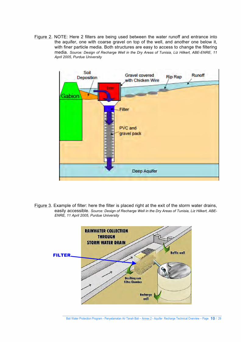
Figure 2. NOTE: Here 2 filters are being used between the water runoff and entrance into
the aquifer, one with coarse gravel on top of the well, and another one below it, with finer particle media. Both structures are easy to access to change the filtering media. Source: Design of Recharge Well in the Dry Areas of Tunisia, Liz Hilkert, ABE-ENRE, 11 April 2005, Purdue University
Figure 3. Example of filter: here the filter is placed right at the exit of the storm water drains,
easily accessible. Source: Design of Recharge Well in the Dry Areas of Tunisia, Liz Hilkert, ABE-ENRE, 11 April 2005, Purdue University
FILTER

Bali Water Protection Program - Penyelamatan Air Tanah Bali – Annex 2 - Aquifer Recharge Technical Overview – Page / 29
11
Figure 4. Example of structures to protect and identify water reservoirs / wells. Source: The Social Work and Research Centre ("SWRC"), Barefoot College, presentation by Bunker Roy at TED, 2011
This structure protects a well fed by rainwater harvested from several rooftops to a quantity of 270 m3. The Barefoot College built rainwater fed wells in 500 schools and estimated the annual collection of 300,000 Million liters. They also built 100-feet diameter open wells allowing to collects 1 Million liters rainwater.
Geodesic Dome 50,000 Liters tank below

Bali Water Protection Program - Penyelamatan Air Tanah Bali – Annex 2 - Aquifer Recharge Technical Overview – Page / 29
12
Figure 4. Example of bore well digging for aquifer replenishment to service 830 houses and 3000 habitants for the Belawadi village in Temgadlore Karnataca State, India. 17 bore wells were installed.
1. Boring of a new well, placed in close distance to existing bore wells. Here drilling a 9-inch (228.6 mm) diameter hole at a depth of 50 feet (15.24 meters).
2. Filling up of the borer well with small
gravel to the height of 5 feet (1.52 meters) 3. Inserting of a 30 feet (99.1 meters) long pipe of 140mm diameter pipe perforated with holes. The bottom pipe (in blue color) fitted to the perforated pipe is not perforated and goes at the bottom of the well. 4. Once the pipe is placed inside the borehole, gravel is placed to
fill the space around the hole. Stormwater can now be oriented to it.

Bali Water Protection Program - Penyelamatan Air Tanah Bali – Annex 2 - Aquifer Recharge Technical Overview – Page / 29
13
Figure 5. Example of wells either installed or refitted used for aquifer replenishment by
gravity-fed wells: Here wells are 5 feet diameter (1.52 meters) and 15 feet deep (4.57 meters).
1. Once the well is dug, reinforced concrete rings are placed to line the well and impede it
of potential eventual collapse. Here 13 rings are used per well, with a height each of 1 foot
(0.30 meters) and of 4.5 feet diameter (1.37 meters diameter).
2. Once all the 13 rings have been placed, a perforated reinforced concrete slab is placed on top and then 2 more rings are placed on top of the perforated slab to act as a
filter. The photo below shows the man standing on top of the concrete slap and
installing the 2 additional rings above the slab
.
3. The 2 rings on top of the concrete slap are filled with 20 centimeters filtering medias: Here (from the top of the slab to the surface):
. 40mm diameter crushed stones up to 5 cm.
. Activated carbon and Charcoal up to 5cm
. 20mm diameter crushed stones up to 10cm
. Gravel sand up to 10cm
Bali Water Protection Program - Penyelamatan Air Tanah Bali – Annex 2 - Aquifer Recharge Technical Overview – Page / 29
14
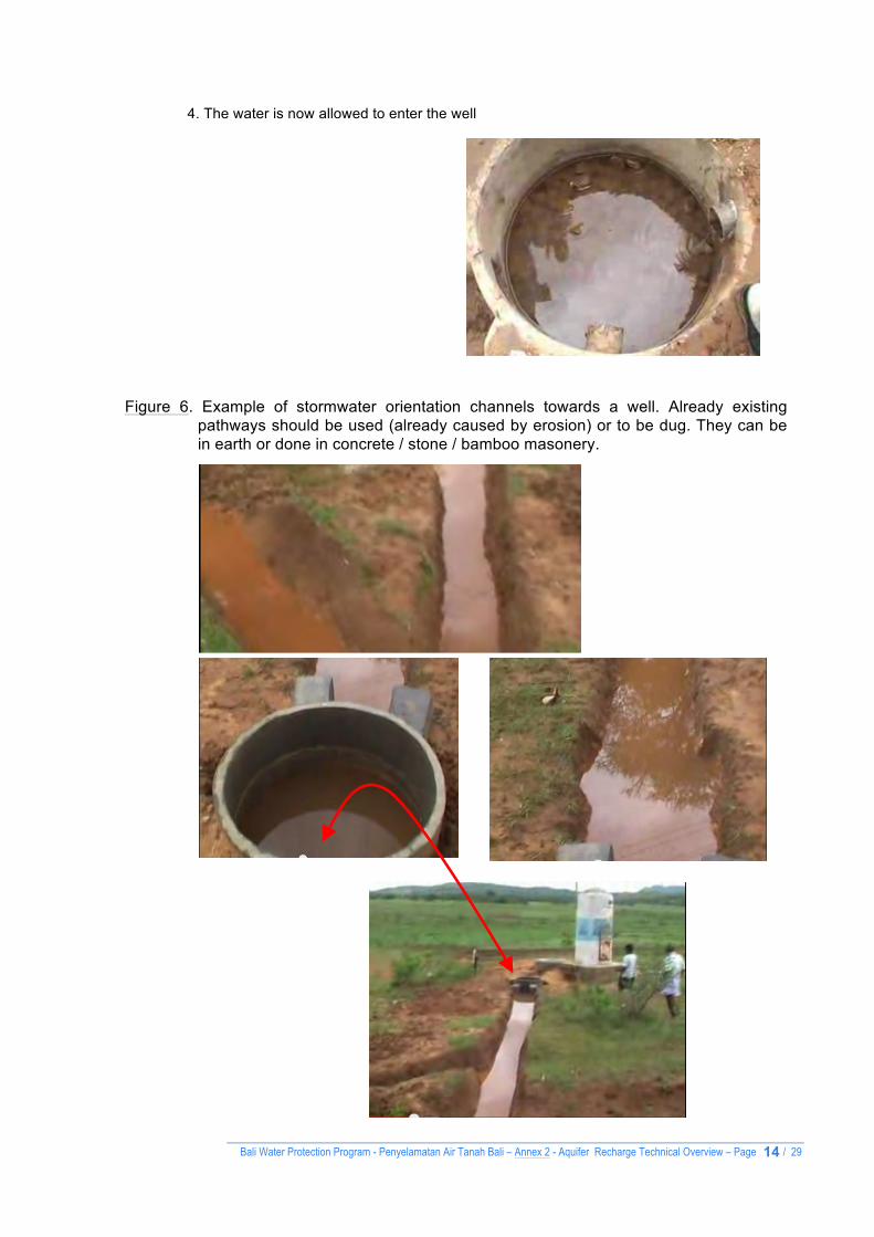
4. The water is now allowed to enter the well Figure 6. Example of stormwater orientation channels towards a well. Already existing
pathways should be used (already caused by erosion) or to be dug. They can be in earth or done in concrete / stone / bamboo masonery.

Bali Water Protection Program - Penyelamatan Air Tanah Bali – Annex 2 - Aquifer Recharge Technical Overview – Page / 29
15
Figure 7. Example of settling tank calculations when a tank is used as holding and filtering
structure between rainwater collection and aquifer recharge. The capacity of the tank should be enough to retain the runoff occurring from conditions of peak rainfall intensity. The rate of recharge in comparison to runoff is a critical factor. Since accurate recharge rates are often not available without detailed geo-hydrological studies, the rates tend to be assumed. The capacity of recharge tank is designed to retain runoff from at least 15 minutes rainfall of peak intensity. Source: How to Design Groundwater Recharge Structure, http://www.rainwaterharvesting.org
For Delhi, India, for example, peak hourly rainfall is 90 mm (based on 25 year frequency) and 15 minutes peak rainfall is 22.5 mm/hr, say 25 mm, according to CGWB norms. For an area of 100 m2 for example, the volume of a desilting tank required in Delhi would be = 100 x 0.025 x 0.85 = 2.125 m3 (2,125 litres)
Figure 8. Rehabilitating existing wells: Recharge in dried-up wells. Source of Drawing: Water
Conservation Technical Briefs, TB2 - Rainwater Harvesting and Artificial Recharge to Groundwater, SAI Platform, August 2009.

Bali Water Protection Program - Penyelamatan Air Tanah Bali – Annex 2 - Aquifer Recharge Technical Overview – Page / 29
16
Overview of Case studies
Example of rainwater-fed aquifer resplenishment

Bali Water Protection Program - Penyelamatan Air Tanah Bali – Annex 2 - Aquifer Recharge Technical Overview – Page / 29
17
EXAMPLES OF CASE STUDIES
§ Rainwater harvesting can recharge the declining groundwater levels in cities. Data from 11 rainwater-harvesting projects spread across Delhi and Gurgaon (Haryana) shows an increase of 5 to10 meters in the groundwater levels over two years. These are the results of a survey from May 2002 to May 2004 on the level of groundwater in rainwater harvesting sites, carried out by the Centre for Science and Environment (CSE). The impact of rainwater harvesting on the quality and quantity of groundwater in the location has been remarkable, proving beyond doubt that rainwater harvesting is one of the most effective tools to arrest the rapidly depleting groundwater reserves. (Source: “India, Delhi: increase in groundwater level in rainwater harvesting Sites”, WASH News and FeaturesCSE Press Release, 15 Jun 2004).
§ India’s Ministry of Water Resources undertook several decade long programs of aquifer freshwater resplenishment via artificial recharge of groundwater as wide spread declines were observed in the water level in the country. During a period running 2003-2005 several structures were build and/or rehabilitated to accelerate the rate of rainwater infiltration into the aquifer with the following results:
§ The following example from a village, Hiware Bazar, in Nagar Block, Maharashtra: It is a dry area that has been greatly affected by deforestation. As the hills lost their vegetation cover, the runoff ruined the fields and water tables dropped. The traditional water storage systems were in ruins and in 1990, only a small part of the cultivable land could be farmed outside the monsoon season. The village managed to turn this situation completely around. Together with progressive authorities, they decided to use their funds and manpower to restore their forests and build 40,000 contour trenches around the hills to conserve rainwater and recharge groundwater. 1,000 ha of land in the area were restored at a cost of about $ 100 per hectare. The funds and labour were well spent. The water level in the wells, which had fallen to 90 meters in 1998, was in 2007 stable at 10 meters. The number of wells and area of irrigated land has more than doubled. Production of grass for cattle feed and milk production has increased hugely.

Bali Water Protection Program - Penyelamatan Air Tanah Bali – Annex 2 - Aquifer Recharge Technical Overview – Page / 29
18
The village has started to grow crops that require less water. Many of the people who had left the land for the city slums have returned and have prospered. In 1995, 168 families out of 180 were below the poverty line. Now there are only three such households. In the past 15 years, average income has risen 20 times. (Source: Restoring water tables in India, by Green World Recycling, Gaia Info Series N˚ 3).
§ About 2,000 residents in Kulgaon-Badlapur, one of the faster growing towns in Mumbai (Bombay), India, now get water 24 hours a day, 7 days a week from a rainwater harvesting system, which provides about 100 liters per person per day A rainwater harvesting demonstration unit was constructed in March 2007 that connects the roofs of 36 apartment buildings. Rainwater is directed into an underground "absorption pit" to recharge the groundwater table. An aboveground storage tank with an electric pump draws water from underground when needed. A hydropneumatic system automatically switches on the pump whenever the water level goes down for individual buildings. The system includes a water treatment plant that filters and treats the water with alum and sodium hypochlorite. The main funding for the INR 1.7 million (US$ 43,300 or EUR 29,500 in 2009-2010 (TBC)) project was raised through a grant and interest-free loan from the Mumbai Metropolitan Region Development Authority (MMRDA). Each household pays only 2 to 3 rupees a day (4-5 euro cents), which covers maintenance costs and full loan payment within 2 years. A Powerpoint presentation of the project, by Pollucon Enviro Engineers, is available of the Kulgaon Badlapur Municipal Council.

Bali Water Protection Program - Penyelamatan Air Tanah Bali – Annex 2 - Aquifer Recharge Technical Overview – Page / 29
19
§ The city of Coimbatore grew
along the banks of River Noyyal that consists of a system of canals, channels, anicuts and lakes. But negligence and pollution due to the rapid growth of industries clubbed with population growth and urbanization, resulted in depletion of ground water beyond economical pumping state. The UNDP studies in 1980s, declared Coimbatore drought-prone, with the fastest depletion of ground water level in the whole world. The year 2003 witnessed Coimbatore in its worst, with ground water table levels as low as 1000 feet deep and the green cover of Mother Nature getting depleted. Even drinking water started to become a very scarce commodity at alarming levels. Coimbatore became a hot plate, emanating heat with little water and green cover to support. People were reminded of the warning – a third world war for water?! Citizens’ response was positive; their needs roped them in to do something for their city, and thus was formed Siruthuli, meaning ‘a little drop’ (in Tamil) in June 2003. A Geo-hydrological study was carried out in the year 2004 to assess the feasibility of construction of rainwater harvesting (RWH) structures towards enabling the recharge of groundwater table with the available run-off water that flows on the roads/streets of Coimbatore city. The end result of the study recommended having a minimum of 600 nos. of RWH structures across the city. To address this problem, Siruthuli decided to take up this project and to accomplish it in a phased manner. Considering the hard rock strata of the Coimbatore region, two different types of structures have been constructed for roadside and open space rainwater harvesting. Each structure consists of a deep bore well, recharge pit, percolation/filter chamber filled with filter materials and concrete slabs. In Phase I, Siruthuli constructed 154 Nos of rainwater harvesting structures (RWHS) during 2004-2005 and 2005-2006 with the financial assistance from the Coimbatore Corporation, utilizing 0.09 Million USD. The structures have been constructed in areas where water logging was observed in four zones of the city. The Rainwater Harvesting Structures proved efficient in recharging the groundwater table and hence from 2005 onwards it was observed that the water levels of Coimbatore city have risen in all zones. The present static water levels are between 15 ft to 60 ft depth in all the zones. The failed bore wells and open wells started yielding enough water for the farmers and the citizens. This shows the efficacy of the rainwater harvesting structures constructed during 2004-06. Phase II: Shri Ram Mohan Mishra IAS, Joint Secretary – MoWR visited a few RWHSs constructed by Siruthuli in the Phase I. Seeing the efficacy of these structures, Central Ground Water Board, Ministry of Water Resources(MoWR), Govt. of India has sanctioned 0.22 Million USD to construct 215 more structures within the city to harvest the run-off water from the roads and open spaces. A District Level Technical Coordination Committee (DLTCC) has been formed under the Chairmanship of the District Collector, Coimbatore for technical guidance for proper implementation of the project and it comprises of The Regional Director - CGWB, Chennai, The City Engineer – Coimbatore Municipal Corporation, The Chief Engineer, Public Works Department, Govt of Tamil Nadu, The Chief Engineer – Tamil Nadu Water Supply and Drainage Board, Coimbatore, Managing Trustee – Siruthuli and Project Coordinator – Siruthuli. This project got inaugurated on 2nd December 2009, and since then the work is progressing well under the supervision of District Level Technical Coordination Committee. 70% of the work has been completed in all aspects utilizing the 1st installment of 0.15 Million USD received from CGWB. The construction of the remaining 30% will commence as soon as the IInd installment of 0.07 Million USD is received from CGWB. The Regional Director, CGWB, Chennai has informed that this type of Rainwater harvesting has been discussed at high
Bali Water Protection Program - Penyelamatan Air Tanah Bali – Annex 2 - Aquifer Recharge Technical Overview – Page / 29
20
level technical committees in New Delhi and has been recommended to follow in all National Highways and Railway lines for proper recharge of runoff rainwater on the either side of National Highways and Railway lines. It also ensures prevention of damages to the roads and rail lines. Thrissur District Kerala. Supported by Government of Kerala & Arghyam Trust Bangalore. For its meritorious services, Siruthuli is conferred three awards: · The “Green Globe Foundation Awards 2010” by TERI and Wizcraft Foundation, under the category of “Extra Ordinary Work done by an NGO” was honoured to Siruthuli on 5th February 2010, · The “Ground Water Augmentation Awards & Bhoomijal Samwardhan Puraskar 2008” by Ministry of Water Resources, Govt of India was received from Shri P K Bansal on 22nd March 2010, · “Shri G. K. Sundaram Award 2010” by Indian Chamber of Commerce and Industry, Coimbatore region, for the innovative efforts and achievements in the fields of Water Resources Management and Environmental Awareness and protection.
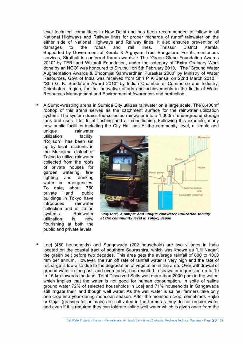
§ A Sumo-wrestling arena in Sumida City utilizes rainwater on a large scale. The 8,400m2
rooftop of this arena serves as the catchment surface for the rainwater utilization system. The system drains the collected rainwater into a 1,000m3 underground storage tank and uses it for toilet flushing and air conditioning. Following this example, many new public facilities including the City Hall has At the community level, a simple and unique rainwater utilization facility, “Rojison”, has been set up by local residents in the Mukojima district of Tokyo to utilize rainwater collected from the roofs of private houses for garden watering, fire-fighting and drinking water in emergencies. To date, about 750 private and public buildings in Tokyo have introduced rainwater collection and utilization systems. Rainwater utilization is now flourishing at both the public and private levels.
§ Loej (480 households) and Sangawada (202 household) are two villages in India
located on the coastal tract of southern Saurashtra, which was known as `Lili Nagar', the green belt before two decades. This area gets the average rainfall of 800 to 1000 mm per annum. However, the run off rate of rainfall water is very high and the rate of recharge is low also due to the degradation of vegetation in the area. Over withdrawal of ground water in the past, and even today, has resulted in seawater ingression up to 10 to 15 km towards the land. Total Dissolved Salts was more than 2000 ppm in the water, which implies that the water is not good for human consumption. In spite of saline ground water 72% of selected households in Loej and 71% households in Sangawada still irrigate their land though well water. As the well water is saline, farmers take only one crop in a year during monsoon season. After the monsoon crop, sometimes Rajko or Gajar (grasses for animals) are cultivated in the farms as they do not require water and even if it is required they can tolerate saline well water which is given once from the

Bali Water Protection Program - Penyelamatan Air Tanah Bali – Annex 2 - Aquifer Recharge Technical Overview – Page / 29
21
recharged well. Groundnut is the major crop in both the villages as it is also major crop in whole Junagadh district. 95% of selected households in Loej and 89% in Sangawada grow Groundnut as major crop. Groundnut being a major crop uses up maximum share of well water. Water from the well is also irrigated for vegetables, Jowar and Rajko. Water is only once used from well when rainfall does not fall in the last phase of monsoon period. This is required because if last water is not given to groundnut, the crop is likely to fail. The impact of salinity is very adverse on the regional economy and ecology. Some of the problems created here were:
• Acute crises of drinking water • Decline in milk production and in cattle population, • Out migration • Low literacy level as enrolment and drop out rates are adverse, specifically in girls, as they have to help their families in fetching water from distant places. • Decline in agricultural productivity and
• Increase in unemployment and poverty. Houses are located scattered in both the villages. While some households are located in the village center, others are located on farmsteads (Vadis). Ahir, Rabari, Koli and Harijans dominate community of both villages. Around 65% of beneficiaries adopted well recharging techniques. → The number of farmers having water after four months has increased three times,
from 7 before recharging to 24 after recharging wells. → 50% of farmers who had water in their wells for less than one month before
recharging wells now enjoy water availability more than one month after the monsoon season.
→ In Sangawada, the number of farmers who can water their crops more than three times has increased from 29 to 42 after recharging wells.
→ Almost 27.6% (29 farmers) of beneficiaries can water their crops for more than 200 hours after recharging wells (who used to water their crops only for 50 hours at the maximum capacity before recharging wells). After 50 hours of watering they get salty water.
→ Of all the beneficiaries, forty percent (42 farmers) have reported increase in hours for watering sweet water to their crops after recharging their wells.
→ The impact of well recharging is quite significant in both the villages. The impact of its work is visible in two ways; firstly a recharged well can provide sweet drinking water throughout the year in highly saline areas. Secondly, it can save the crop by providing last sweet water irrigation when the last monsoon fails in the region. (Source: Evaluation of Well Recharge as an Effective Tool for Reducing Salinity in Shallow

Bali Water Protection Program - Penyelamatan Air Tanah Bali – Annex 2 - Aquifer Recharge Technical Overview – Page / 29
22
Coastal Aquifer, Aga Khan Rural Support Program (India)).

Bali Water Protection Program - Penyelamatan Air Tanah Bali – Annex 2 - Aquifer Recharge Technical Overview – Page / 29
23
Rainwater Collecting from buildings
Note: Although BWP is not currently addressing rainwater collection from buildings, some information is enclosed for relevant sustainable water management good practice.

Bali Water Protection Program - Penyelamatan Air Tanah Bali – Annex 2 - Aquifer Recharge Technical Overview – Page / 29
24
1. Options of rainwater storage location
2. Options of roof-top rainwater collection techniques
Figure 1. Rainwater collection options Chosen options will depend on local situation and cost. Source of Drawing: Rainwater Harvesting, RWH Cell, Kamatak State Council for Science and Technology, Indian Institute of Science, Indian Institute of Bangalore 560 012, A. R. Shivakumar, India.

Bali Water Protection Program - Penyelamatan Air Tanah Bali – Annex 2 - Aquifer Recharge Technical Overview – Page / 29
25
Here roads are built in such a way as to facilitate rainwater collection and ground water recharge through road-side trenches. They are about 600mm wide and 600mm depth, filled with pebbles /aggregates with a top layer of coarse sand.
Figure 2. Examples of different ways to recharge the water table in urban environments.
Here the rainwater is used both for usage and to refill the aquifer. Source: State Council for Science and Technology, Indian Institute of Science, Bangalore, India.
Protection on top of an open well
Open trenches as collectors

Bali Water Protection Program - Penyelamatan Air Tanah Bali – Annex 2 - Aquifer Recharge Technical Overview – Page / 29
26
A barrel system is used here: the overflow of the rainwater storage
tank goes through a series of barrels with open bottoms
Figure 3. Schematic installation of the barrel system as rainwater collector for reuse or ‘canalizator’ of rainwater for aquifer resplenishment:

Bali Water Protection Program - Penyelamatan Air Tanah Bali – Annex 2 - Aquifer Recharge Technical Overview – Page / 29
27
Figure 4. Options of rainwater storage containers
Figure 5. Example of rainwater filters

Bali Water Protection Program - Penyelamatan Air Tanah Bali – Annex 2 - Aquifer Recharge Technical Overview – Page / 29
28
Figure 6. Example of retrofitting buildings for rainwater collection
Figure 7. Example of bamboo gutters

Bali Water Protection Program - Penyelamatan Air Tanah Bali – Annex 2 - Aquifer Recharge Technical Overview – Page / 29
29
Figure 8. Ideal sustainable rainwater management scheme: storage for reuse and aquifer replenishment
-----
End of Annex 2