water service plan design manual - columbus
TRANSCRIPT

Water Service Plan
Design Manual
August 2018


Table of Contents
Page
Preface……………………………………………………………………………………………..1
1.0 Water Service Plans…………………………………….………………………….2-9
1.1 Overall Site plan
1.2 Profile View
1.3 Meter and Backflow Setting Detail
1.4 Water Service Notes
2.0 Water Service Design .………………………………………………….….…….9-16
2.1 Tapping Valves and Control Valves
2.2 Abandonments
2.3 Meter and Backflow Prevention
2.4 Fire Services and Fire Hydrants
3.0 Submittals...……………………………………………………………………………….16
4.0 Revisions to Approved Plans………………………………………………..…….17
5.0 Water Service Plan Expiration…………………………………………………….17
Appendix
Border Template

1
Preface
The following document shall serve as a guideline for water service design within
the Division of Water service area. This includes the City of Columbus and
communities with Full Service Water Agreements with the City of Columbus.
These communities include: Brice, Brookside Estates, Dublin, Grandview Heights,
Grove City, Groveport, Hamilton Meadows, Hilliard, Marble Cliff, Minerva Park,
New Albany, Ridgewood Estates, Riverlea, Urbancrest, Upper Arlington,
Valleyview, Village Park, Whitehall and Worthington.
It was prepared to assist engineering consultants in the development of water
service plans. These guidelines are not all inclusive and do not replace good
engineering judgment. Any deviation from these guidelines shall be approved by
the Division of Water plan reviewer. All technical details shall remain the
responsibility of the engineer preparing the plans.
The Division reserves the right to modify any or all of these guidelines at any time.
For the purposes of this manual, the following definitions shall be used for tap
and service line:
“Tap” means the connection to the water main and the necessary pipes or lines
extending from the water main to and including the curb stop or valve and box.
(City owned)
“Service line” means the line extending from the tap onto the premises to be
served and shall include all the necessary pipes, lines and appurtenances from the
tap to and including the meter and backflow device. This also includes lines that
are outside the footprint(s) of the building(s) on the site. This includes domestic
lines between buildings, fire lines, private hydrants, fire department connections,
etc. (privately owned)

2
1.0 Water Service Plans
1.0.1 All additions, extensions, demolitions, and modifications of a new or
existing water tap or service line 3” or larger in diameter will require a
water service plan submission and approval. Water service plans will also
be required for all non-residential properties that require backflow
regardless of the size of the tap or service line.
1.0.2 All water service plans submitted for approval by the City of Columbus
shall be prepared, signed, and sealed by a Professional Engineer who is
licensed in the State of Ohio.
1.0.3 It is the responsibility of the engineer to know and follow the latest
edition of the City of Columbus Construction and Material Specifications
(CMSC), the City of Columbus, the Department of Public Utilities Rules and
Regulations, and Division of Water Standard Drawings. The latest editions
of these items can be found in the Department of Public Utilities
“Document Library” on the City of Columbus website:
www.columbus.gov/utilities/document-library/.
1.0.4 Water service plans are for water service work only. Public water main or
fire hydrant installations, relocations or abandonments shall be prepared
on a separate plan. This can be done under a street improvement plan or
a water line only plan. If a public hydrant is being installed using the tap
as the hydrant lead, and the hydrant lead is no more than 20 feet, it can
be shown as part of the water service plan. A separate plan will not be
required.
1.0.5 Water service plans shall be separate, stand-alone plans. They shall not
be part of a larger plan (i.e., street improvement plan, site development
plan, etc.).
1.0.6 Water service plans shall follow the “Computer Aided Drafting (CAD)
Standards for Creation and Submittal of Digital Drawings”. The standards
document can be found in the Department of Public Utilities “Document
3
Library” on the City of Columbus website:
www.columbus.gov/utilities/document-library/
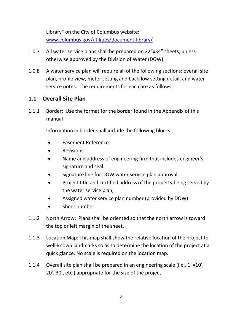
1.0.7 All water service plans shall be prepared on 22”x34” sheets, unless
otherwise approved by the Division of Water (DOW).
1.0.8 A water service plan will require all of the following sections: overall site
plan, profile view, meter setting and backflow setting detail, and water
service notes. The requirements for each are as follows:
1.1 Overall Site Plan
1.1.1 Border: Use the format for the border found in the Appendix of this
manual
Information in border shall include the following blocks:
Easement Reference
Revisions
Name and address of engineering firm that includes engineer’s
signature and seal.
Signature line for DOW water service plan approval
Project title and certified address of the property being served by
the water service plan,
Assigned water service plan number (provided by DOW)
Sheet number
1.1.2 North Arrow: Plans shall be oriented so that the north arrow is toward
the top or left margin of the sheet.
1.1.3 Location Map: This map shall show the relative location of the project to
well-known landmarks so as to determine the location of the project at a
quick glance. No scale is required on the location map.
1.1.4 Overall site plan shall be prepared in an engineering scale (i.e., 1”=10’,
20’, 30’, etc.) appropriate for the size of the project.

4
1.1.5 All work should be designed on the Ohio State Plane Coordinate System
(South), unless otherwise approved by DOW.
1.1.6 Show the entire site. Label all property lines and surrounding streets.
1.1.7 Show and label corporate boundaries.
1.1.8 Show all street edges, curbs and right-of-way. This also includes any
existing or proposed easement lines.
1.1.9 Label the right-of-way width. If the right-of-way is proposed, supporting
documents from the agency responsible for the right-of-way acquisition
need to be included with the water service plan submittal to ensure
proposed right-of-way lines are accurate and definite.
1.1.10 Label each parcel with the street address and parcel identification
number.
1.1.11 Water service plan shall include a certified address of the property being
served. The water service plan will not be approved until a certified
address is obtained.
1.1.12 All existing and proposed utilities within, or adjacent to, the project site
shall be shown on the plan and clearly identified as to type, size, location
and ownership.
1.1.13 Existing water mains shall be labeled with record plan number, size and
material. All existing water taps shall be shown and labeled by tap ID#.
1.1.14 Show the footprint of all existing buildings to remain and proposed
buildings.
1.1.15 Label the building type per the Ohio Building Code on the site plan.
1.1.16 Appropriate line weights are to be used for the various items shown on
the plan. All items shown on the plan are to be labeled and clearly
distinguishable from each other. For ease of distinction, the proposed
water tap and service lines should be the heaviest line weight used.
5
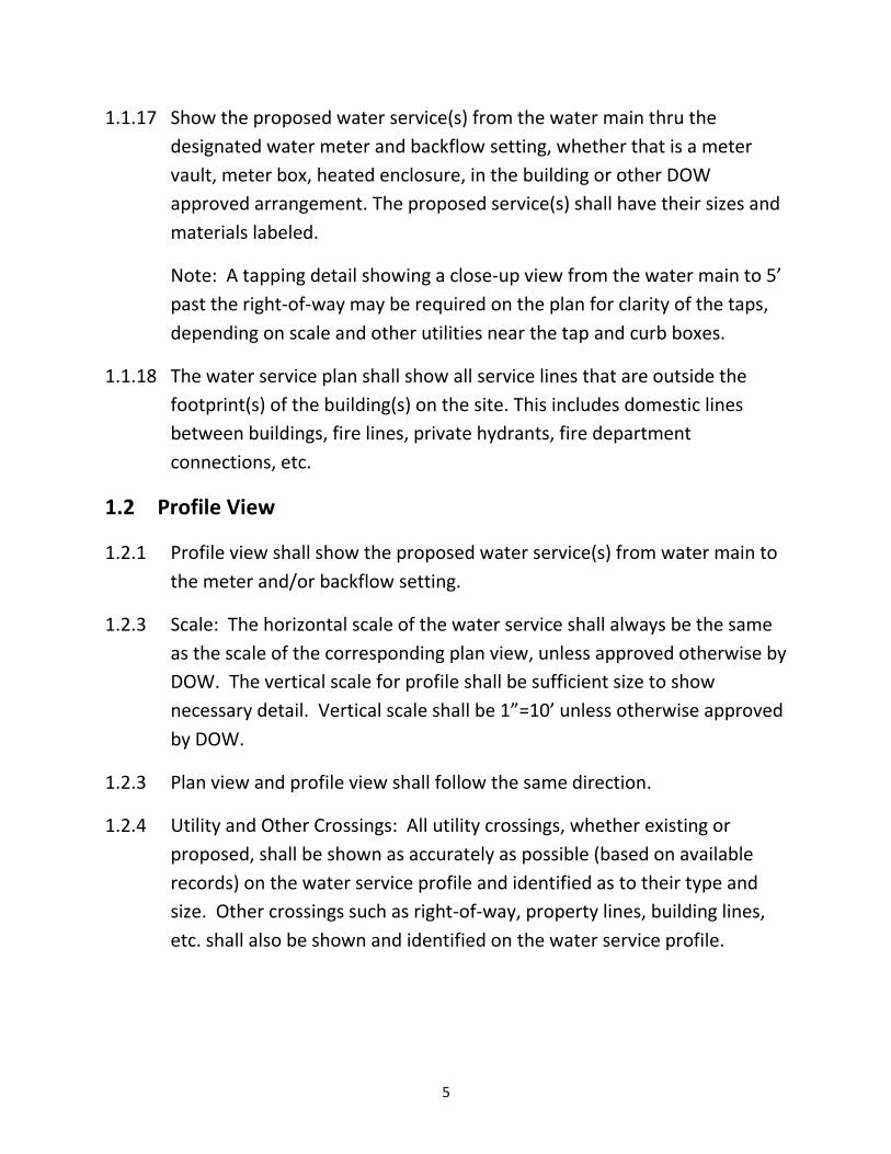
1.1.17 Show the proposed water service(s) from the water main thru the
designated water meter and backflow setting, whether that is a meter
vault, meter box, heated enclosure, in the building or other DOW
approved arrangement. The proposed service(s) shall have their sizes and
materials labeled.
Note: A tapping detail showing a close-up view from the water main to 5’
past the right-of-way may be required on the plan for clarity of the taps,
depending on scale and other utilities near the tap and curb boxes.
1.1.18 The water service plan shall show all service lines that are outside the
footprint(s) of the building(s) on the site. This includes domestic lines
between buildings, fire lines, private hydrants, fire department
connections, etc.
1.2 Profile View
1.2.1 Profile view shall show the proposed water service(s) from water main to
the meter and/or backflow setting.
1.2.3 Scale: The horizontal scale of the water service shall always be the same
as the scale of the corresponding plan view, unless approved otherwise by
DOW. The vertical scale for profile shall be sufficient size to show
necessary detail. Vertical scale shall be 1”=10’ unless otherwise approved
by DOW.
1.2.3 Plan view and profile view shall follow the same direction.
1.2.4 Utility and Other Crossings: All utility crossings, whether existing or
proposed, shall be shown as accurately as possible (based on available
records) on the water service profile and identified as to their type and
size. Other crossings such as right-of-way, property lines, building lines,
etc. shall also be shown and identified on the water service profile.

6
1.2.5 Ground Surfaces: Existing and proposed ground surfaces shall be shown
and clearly marked. Existing surfaces shall be shown as a dashed line.
Proposed ground surfaces shall be shown as a solid line.
1.2.6 All elevations shown on the plan shall be based on the North American
Vertical Datum of 1988 (NAVD 88), unless otherwise approved by DOW.
1.2.7 Control Valve: All control valves installed with the water service shall be
shown and identified as to their type and size on the water service profile.
1.3 Meter and Backflow Setting Detail
1.3.1 Water meters should be installed in above ground structures whenever
practical. If it is not practical to get the water meter in an above ground
structure, the water meter can be placed in a meter vault.
1.3.2 Whether the water meter is placed in a structure or in a vault, it can be
shown as part of the overall site plan.
1.3.3 If a backflow preventer is required, it shall be placed as close to the meter
as is reasonably practical, and prior to any other connection. Whether a
backflow preventer is located above ground or below is dependent on the
type of containment required as prescribed in the current Rule and
Regulation for Cross-Connection Control. A double check valve assembly
can be placed in a vault. A reduced pressure backflow assembly (RP) shall
not be installed in a vault or any area subject to flooding.
1.3.4 The water meter and backflow preventer (if required) shall not be located
within a living unit of a 2 or more multiple unit residential site.
1.3.5 It is the responsibility of the engineer to determine the most appropriate
location for the meter and backflow preventer based on the site and DOW
requirements. Location shall require the approval of DOW.
1.3.6 If the water meter is placed in a vault, the engineer shall show the meter
and vault according to the latest edition of the DOW Standard Drawings.
Any backflow prevention required shall be shown as well.

7
1.3.7 If the meter and backflow preventer is to be placed inside a structure, the
MEP plans for the structure can be submitted for review.
1.3.8 MEP plans are only required if the meter and backflow preventer
information is not shown on the overall site plan due to responsibilities of
the respective engineer.
1.3.9 If a MEP plan is utilized, it is the responsibility of the engineer submitting
the water service plan to ensure that the MEP plan matches the overall
site plan in regards to the water service size and where it enters the
building. If the plans do not match, they will be returned to the engineer
with no further review completed.
1.3.10 If a MEP plan is used, it does not need to include the plumbing for every
floor behind the meter.
1.3.11 The MEP plan can be prepared in an architectural scale. If no scale is
used, all dimensions must be shown to ensure meter and backflow setting
meets DOW access and spacing requirements.
1.3.12 The meter room must be shown in plan and profile view. Both views
must show the meter and/or backflow setting to ensure meter and/or
backflow setting meets DOW access and spacing requirements.
1.3.13 If the meter room is designed with a RP backflow assembly, DOW
recommends that a floor drain be installed and sized per the RP
manufacturer’s specifications. The location and size of the floor drain is
subject to the approval of the local building department.
1.3.14 The meter room shall meet all code provisions required by the local
building department.
1.3.15 If a separate, dedicated meter building is being used, the heat source shall
be shown on the plan for the building.
1.3.16 For the plan view of meter and/or backflow setting:

8
Show that meter and/or backflow setting meets DOW access and
spacing requirements. Dimension from the nearest existing or
proposed wall, and dimension proper clearances from any other
utilities or mechanical devices that may be in the same room.
Show the access to the meter and/or backflow setting, and show
the door swing to ensure the door is able to open fully.
If a site has both the fire and domestic meters in the same meter
room, they should both be shown on the same detail.
Show fire and domestic pumps if they are needed:
Fire pumps must be labeled with a low pressure throttling valve or
a variable speed suction limiting control
Domestic pumps must be labeled with a low pressure cut off
switch
1.3.17 For the profile view of meter and/or backflow setting:
If meter is in a vault and backflow is in an above ground heated
enclosure, the profile shall show both the vault and the heated
enclosure.
In all cases, show the dimension from the floor to the center of
pipe.
If a site has domestic and fire services, a profile of each meter
setting is required.
The size and type of each backflow preventer must be labeled.
If an ASSE 1048 device is being used the following note shall be
provided with the call out for the backflow preventer: Fire
protection system uses water only, the site does not have
access to an auxiliary water system, and the system is not
subject to chemical additives.
1.4 Water Service Notes
1.4.1 Water Service Notes shall be included on all plans. The latest edition of
these notes can be found in the Department of Public Utilities “Document
9
Library” on the City of Columbus website:
www.columbus.gov/utilities/document-library/.
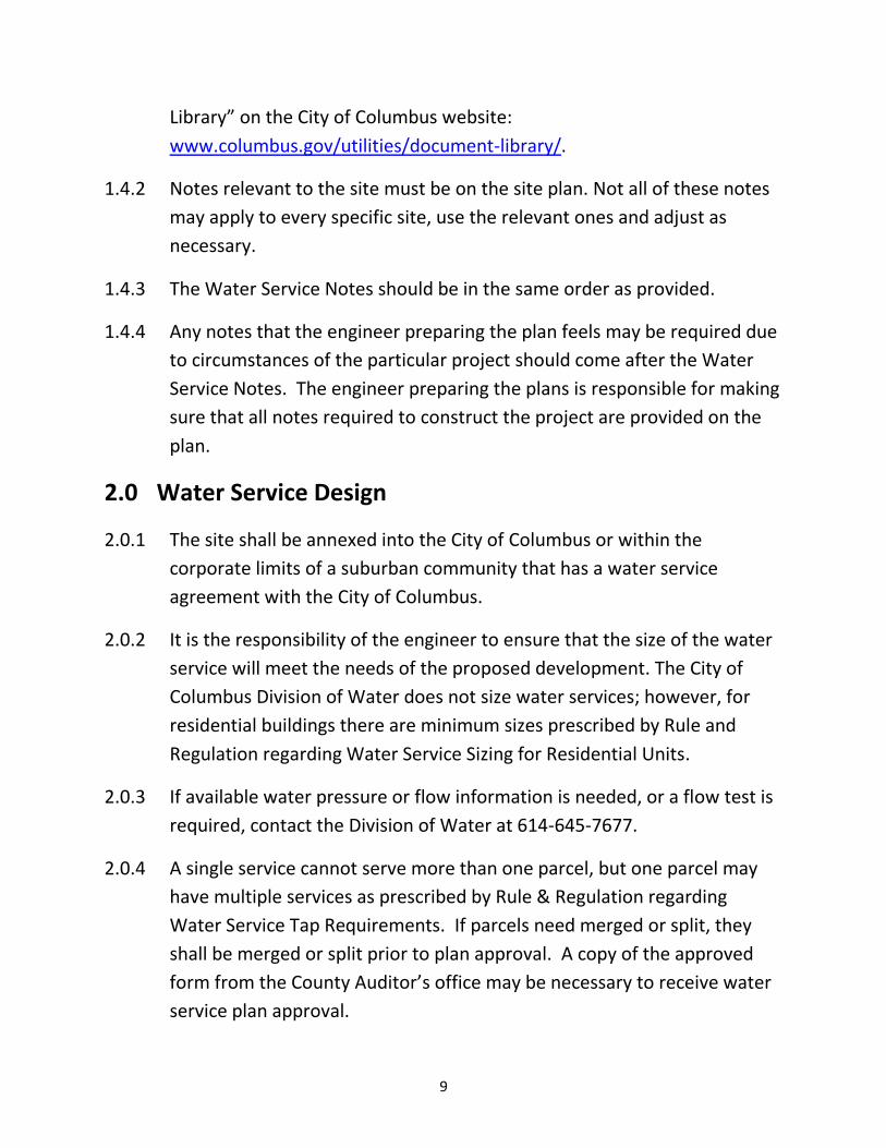
1.4.2 Notes relevant to the site must be on the site plan. Not all of these notes
may apply to every specific site, use the relevant ones and adjust as
necessary.
1.4.3 The Water Service Notes should be in the same order as provided.
1.4.4 Any notes that the engineer preparing the plan feels may be required due
to circumstances of the particular project should come after the Water
Service Notes. The engineer preparing the plans is responsible for making
sure that all notes required to construct the project are provided on the
plan.
2.0 Water Service Design
2.0.1 The site shall be annexed into the City of Columbus or within the
corporate limits of a suburban community that has a water service
agreement with the City of Columbus.
2.0.2 It is the responsibility of the engineer to ensure that the size of the water
service will meet the needs of the proposed development. The City of
Columbus Division of Water does not size water services; however, for
residential buildings there are minimum sizes prescribed by Rule and
Regulation regarding Water Service Sizing for Residential Units.
2.0.3 If available water pressure or flow information is needed, or a flow test is
required, contact the Division of Water at 614-645-7677.
2.0.4 A single service cannot serve more than one parcel, but one parcel may
have multiple services as prescribed by Rule & Regulation regarding
Water Service Tap Requirements. If parcels need merged or split, they
shall be merged or split prior to plan approval. A copy of the approved
form from the County Auditor’s office may be necessary to receive water
service plan approval.

10
2.0.5 When a property within the corporation limits of the City of Columbus is
to be served with water by tapping a water main owned by another
suburban community, it is the responsibility of the engineer to notify the
owner of the water main to make them aware of the proposed
development and the intentions to tap their water main. The DOW plan
reviewer may request documentation that demonstrates the suburban
community’s acknowledgement of these intentions.
2.0.6 Water taps shall be perpendicular to the water main. No tap or service
line shall run parallel to the right-of-way while within the right of way or
water main easement area.
2.0.7 Water taps should be located as to minimize the impact on existing trees.
2.0.8 A minimum of 3’ shall be maintained between fittings on the water main.
2.0.9 Water services shall maintain 10’ horizontal and 18” vertical separation
from sanitary and storm sewer piping (outside diameter to outside
diameter) unless otherwise approved by DOW. Maintain 3’ horizontal
and 12” vertical separation from all other utilities unless otherwise
required by the applicable utility company.
2.0.10 Water service pipe shall be the same size from the main to the meter,
unless otherwise approved by DOW.
2.0.11 Water taps and service lines 3” and larger shall be ductile iron through the
meter and backflow setting including the meter bypass.
2.0.12 Water taps 2” and smaller shall be Type K copper tubing as prescribed by
Rule and Regulation regarding Materials for Water Service Taps.
2.0.13 Water service lines 2” and smaller shall either be Type K copper tubing or
ultra-high molecular weight polyethylene tubing as prescribed by Rule
and Regulation regarding Service Line Materials Upstream from the Water
Meter.

11
Note: If there are underground petroleum storage tanks on site, water
service lines 2” and smaller must be Type K copper tubing as prescribed
by Rule & Regulation regarding Water Service Material on Properties with
Underground Storage Facilities.
2.0.14 Proposed water service taps 3” and larger shall be shown a minimum of 4’
below existing or proposed grade. The grade (existing or proposed) which
provides the greatest amount of cover at the time of construction shall
govern.
2.0.15 Proposed water service taps 2” and smaller shall be shown a minimum of
42” below existing or proposed grade. The grade (existing or proposed)
which provides the greatest amount of cover at the time of construction
shall govern.
2.0.16 Ensure that tees, bends and valves are not located below existing utilities.
2.0.17 There shall be no connections (i.e. private hydrants, fire department
connections, post indicator valves, etc.) prior to the meter and only 1
valve shall be permitted upstream of the meter as prescribed in the Rule
and Regulation for Water Metering Systems.
2.0.18 There shall be no more than 150’ of service line from the control valve to
the meter, unless otherwise approved by DOW.
2.0.19 Water service pipe may change size and/or material type at the outlet
flange of the backflow preventer.
2.1 Tapping Valves and Control Valves
2.1.1 Ensure that the size of the proposed tapping sleeve does not exceed the
size of the existing water main. If possible, avoid the use of size-on-size
tapping sleeves (i.e. 6” x 6”) unless no other option is available. It is DOW
preference that size-on-size taps on cast iron water mains have a tee and
valve cut into the existing water main.
2.1.2 If there are separate fire and domestic services:
12
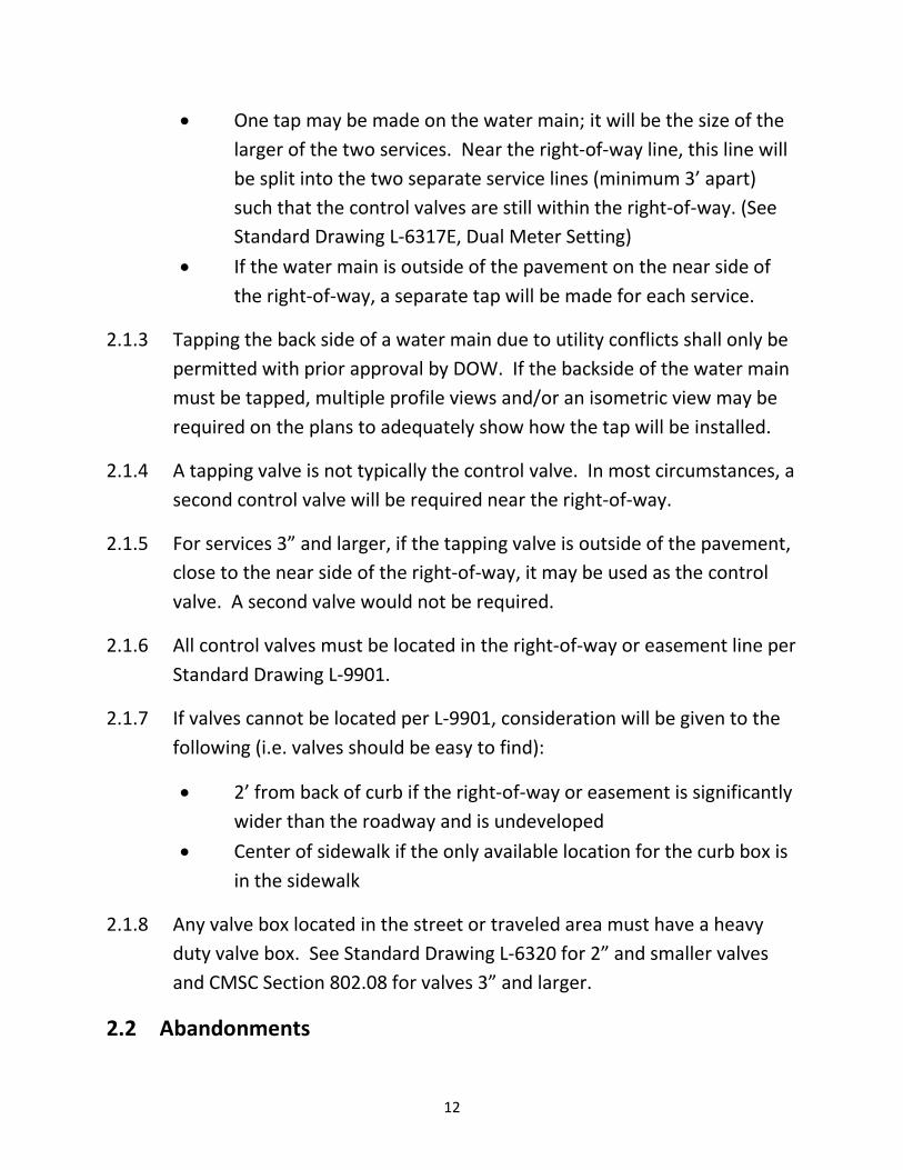
One tap may be made on the water main; it will be the size of the
larger of the two services. Near the right-of-way line, this line will
be split into the two separate service lines (minimum 3’ apart)
such that the control valves are still within the right-of-way. (See
Standard Drawing L-6317E, Dual Meter Setting)
If the water main is outside of the pavement on the near side of
the right-of-way, a separate tap will be made for each service.
2.1.3 Tapping the back side of a water main due to utility conflicts shall only be
permitted with prior approval by DOW. If the backside of the water main
must be tapped, multiple profile views and/or an isometric view may be
required on the plans to adequately show how the tap will be installed.
2.1.4 A tapping valve is not typically the control valve. In most circumstances, a
second control valve will be required near the right-of-way.
2.1.5 For services 3” and larger, if the tapping valve is outside of the pavement,
close to the near side of the right-of-way, it may be used as the control
valve. A second valve would not be required.
2.1.6 All control valves must be located in the right-of-way or easement line per
Standard Drawing L-9901.
2.1.7 If valves cannot be located per L-9901, consideration will be given to the
following (i.e. valves should be easy to find):
2’ from back of curb if the right-of-way or easement is significantly
wider than the roadway and is undeveloped
Center of sidewalk if the only available location for the curb box is
in the sidewalk
2.1.8 Any valve box located in the street or traveled area must have a heavy
duty valve box. See Standard Drawing L-6320 for 2” and smaller valves
and CMSC Section 802.08 for valves 3” and larger.
2.2 Abandonments

13
2.2.1 It is the engineer’s responsibility to do the tap research to ensure that all
of the services that need to be abandoned are shown on the plan.
2.2.2 All tap abandonments shall be identified on the plan.
Abandonments are to be completed per the CMSC Section 808.
2.2.3 If there are 5 or more taps to be abandoned, then a table with tap ID#s
and sizes shall also be added to the plan for ease of reference.
2.3 Meter and Backflow Prevention
2.3.1 Backflow requirements shall meet the current Rule and Regulation for Cross-Connection Control.
2.3.2 Included in the backflow requirements, is the requirement that for all
non-residential properties, an approved backflow prevention assembly shall be installed on each domestic service line and each combined domestic and fire service line to a consumer’s water system.
Note: Upon written request by the customer, an exception to this
requirement may be granted by the Administrator if the customer can demonstrate that the site meets all of the conditions identified in the current Rule and Regulation for Cross-Connection Control.
2.3.3 Any structure or portion of structure that has a fire department
connection and meets the following Use and Occupancy Classification from Section 302 of the Ohio Building Code will be required to have an RP backflow assembly on the fire service line:
High Hazard: Groups H-1, H-2, H-3, H-4 and H-5
2.3.4 Meter size can be same size or one size smaller than service line as
prescribed by Rule and Regulation regarding Water Metering Systems. If
meter size is smaller than service line, reduce above finished floor and
prior to the inlet tee.

14
2.3.5 Meter bypass shall be sized to match the meter size and be the same
material as the service line.
2.3.6 For domestic only services the size of the backflow preventer must match
the size of the meter, unless otherwise approved by DOW.
2.3.7 For fire only services the size of the backflow preventer must match the
size of the service line, unless otherwise approved by DOW.
2.3.8 For combined domestic and fire services, refer to Rule and Regulation for
Cross-Connection Control for backflow preventer size requirements.
2.3.9 Strainers are permitted before the backflow preventer on fire lines and
between the meter and backflow preventer on domestic lines.
2.3.10 Backflow prevention assemblies are provided by the owner of the
property. The property owner is responsible for the installation,
maintenance and replacement of all backflow assemblies. This includes
double check detector assemblies and reduced pressure detector
assemblies used on fire lines.
2.3.11 No backflow prevention assembly shall be subject to excessive heat or
freezing. Above grade exterior installations that remain in service through
the winter shall be installed within an ASSE 1060 Class I heated enclosure
as prescribed by Rule and Regulation regarding Cross Connection Control.
2.3.12 If a heated enclosure is used, the concrete slab shall extend 24” on access
side of the enclosure.
2.3.13 Heat tape and/or heat rods shall not be permitted around any meter
setting or backflow prevention assembly.
2.3.14 No meter vault or meter box shall be installed in any paved area without
the expressed approval of DOW as prescribed in the Standard Drawing L-
6317B, Meter Vault Setting Section View.
2.3.15 The meter vault floor shall be a minimum of 18” above the flow line of the
drainage ditch or storm sewer. Use of a sump pump in lieu of providing

15
adequate drainage is not permitted. This is further described in the
Standard Drawing L-6317B, Meter Vault Setting Section View.
2.3.16 Water meters 2” and larger are not permitted in ASSE 1060 Class I heated
enclosures, unless otherwise permitted by DOW.
2.3.17 When water meters are located in a vault, a 1” conduit shall be provided
for the meter remote wire(s) with the following requirements:
Conduit shall be for the remote wires only. Any other wiring shall
have a separate conduit.
Conduit shall extend 6” into the vault and clear of all access
portals.
Conduit shall contain 1 drawstring for each meter requiring a
remote.
Conduit shall have a minimum bury of 24” from the vault to the
heated enclosure.
Conduit shall extend 18” up into the slab for the heated enclosure
along the heater wall.
2.3.18 When water meters are located in a basement or lower level with poured
concrete walls, a 1” conduit shall be provided for the meter remote
wire(s) with the following requirements:
Conduit shall be for the remote wires only.
Conduit shall extend 6” into the meter area.
Conduit shall contain 1 drawstring for each meter requiring a
remote.
Conduit shall exit an exterior wall between 2’ and 5’ above
finished grade and shall extend 6” outside of the exterior wall.
2.4 Fire Services and Fire Hydrants
2.4.1 It is the engineer’s responsibility to work ahead of time with the local fire
department to ensure that the fire service size, number of private
16
hydrants, private hydrant spacing and any other fire appurtenances are
acceptable to the local fire department prior to water service plan
approval.
3.0 Submittals
3.0.1 Plans shall not be submitted by email. Only hard copy plans will be
reviewed.
3.0.2 All submittals will be directed to:
Bill Stover, DPU Plan Coordinator 910 Dublin Road, 3rd Floor Columbus, Ohio 43215
3.0.3 First submittal will include:
2 copies of the water service plan. This includes 2 copies of the
MEP plans if applicable.
3.0.4 Subsequent submittals will include:
Backcheck of DOW’s most recent review comments
2 copies of revised plans (including MEP plans if applicable) that
reflect DOW’s most recent review comments
3.0.5 Final submittal will include:
Backcheck of DOW’s most recent review comments
5 copies of revised plans (including MEP plans if applicable) that
reflect DOW’s most recent review comments
CD containing TIFF images and CAD basemap following DPU CAD
Digital Submission Standards.
4.0 Revisions to Approved Plans
4.0.1 All revisions to the approved water service plan shall be approved by
DOW.

17
4.0.2 Each revision shall be shown with a numbered triangular box inserted
next to the revised work. A numbered triangular box shall then be placed
in the revision block of the drawing border with a brief and concise
description of the change.
4.0.3 Only 3 relatively small revisions shall be permitted on a water service
plan. Any major revisions, or more than 3 minor revisions, may require
the submission of a new plan.
5.0 Water Service Plan Expiration
5.0.1 Water service plans are valid for 1 year from the date of plan approval. If
inspection by DOW of water service work has not commenced within this
12-month period, the engineer may be required to resubmit for approval.
The engineer may request an extension be granted. This extension must
be approved by DOW.

Appendix

