water reclamation facility basis of design report may 2019
TRANSCRIPT
DRAFT BASIS OF DESIGN MEMORANDUM
Morro Bay WRF
B&V PROJECT NO. 400530
PREPARED FOR
City of Morro Bay, California
2 MAY 2019
2017

City of Morro Bay, California | DRAFT Basis of Design Memorandum
BLACK & VEATCH | Table of Contents i
1.1.1.1.1.1.1 Table of Contents
0 EXECUTIVE SUMMARY ................................................................................................................................ 1
0.1 Project Scope .......................................................................................................................................................... 1
0.2 Design Focus of the BDR and 30% drawings Submittal ....................................................................... 6
0.3 Design Development Efforts in Progress ................................................................................................... 7
1 PROJECT OVERVIEW ................................................................................................................................ 1-1
1.1 Project Background and Drivers ............................................................................................................... 1-1
1.2 Project Description .......................................................................................................................................... 1-1
1.3 Applicable Codes and Design Guidelines ............................................................................................... 1-2
1.4 List of Terms, Acronyms, and Abbreviations ....................................................................................... 1-2
1.5 Jurisdictional Agencies .................................................................................................................................. 1-2
1.6 Project Schedule ............................................................................................................................................... 1-2
1.7 Drafting Standards .......................................................................................................................................... 1-3
1.8 Permitting and Applications ........................................................................................................................ 1-3
1.9 Reference Material .......................................................................................................................................... 1-4
2 EXISTING INFORMATION ....................................................................................................................... 2-1
2.1 WRF Site Information ..................................................................................................................................... 2-1
2.2 Project Datum, Project Benchmarks, Survey Control and Local
Flood Levels ....................................................................................................................................................... 2-1
2.3 Existing Wastewater Treatment PLant .................................................................................................. 2-1
2.4 Existing Utilities ................................................................................................................................................ 2-1
2.5 Geotechnical Information ............................................................................................................................. 2-2
3 PROCESS DESIGN CRITERIA .................................................................................................................. 3-1
3.1 Effluent Quality Requirements ................................................................................................................... 3-7
4 FACILITY DESIGN CRITERIA .................................................................................................................. 4-1
4.1 Headworks – Area 20 ..................................................................................................................................... 4-2
4.2 Treatment Area – Area 30 .......................................................................................................................... 4-10
4.3 RO/UV Building – Area 50 .......................................................................................................................... 4-21
4.4 Effluent Area – Area 60 ................................................................................................................................ 4-28
4.5 Residuals Area – Area 70 ............................................................................................................................ 4-37
4.6 Chemical Storage and Feed Facilities – Area 90 ................................................................................ 4-44
5 CIVIL SITE DESIGN CRITERIA ................................................................................................................ 5-1
5.1 Grading ................................................................................................................................................................. 5-1
5.2 Major Yard Piping ............................................................................................................................................ 5-1
5.3 Drainage ............................................................................................................................................................... 5-1
DRAFT Basis of Design Memorandum | City of Morro Bay, California
ES-ii Executive Summary | May 2019
5.4 Erosion Control ................................................................................................................................................. 5-2
5.5 Landscaping ....................................................................................................................................................... 5-2
5.6 Fencing ................................................................................................................................................................. 5-3
6 STRUCTURAL DESIGN CRITERIA ......................................................................................................... 6-1
6.1 Applicable Codes and Standards ............................................................................................................... 6-1
6.2 Material Properties and Loading Criteria .............................................................................................. 6-2
6.3 Design Procedures and Assumptions ...................................................................................................... 6-8
6.4 Special Inspection and Structural Observation ................................................................................. 6-12
7 ARCHITECTURAL DESIGN CRITERIA .................................................................................................. 7-1
7.1 General ................................................................................................................................................................. 7-1
7.2 Building Codes ................................................................................................................................................... 7-1
7.3 Building Descriptions ..................................................................................................................................... 7-2
8 BUILDING MECHANICAL AND FIRE DESIGN CRITERIA ................................................................ 8-1
8.1 General ................................................................................................................................................................. 8-1
8.2 Applicable Codes and Standards ............................................................................................................... 8-1
8.3 Site and Temperature Design Criteria ..................................................................................................... 8-2
8.4 Materials .............................................................................................................................................................. 8-2
8.5 Seismic .................................................................................................................................................................. 8-3
8.6 Building Design Requirements ................................................................................................................... 8-3
8.7 Plumbing design ............................................................................................................................................... 8-3
8.8 Heating, Ventilation, and Air Conditioning............................................................................................ 8-9
8.9 Fire Protection Design ................................................................................................................................. 8-14
9 ELECTRICAL DESIGN CRITERIA ............................................................................................................ 9-1
9.1 General Electrical Design Criteria ............................................................................................................. 9-1
9.2 Codes and Standards ...................................................................................................................................... 9-1
9.3 Power Distribution Design ........................................................................................................................... 9-1
9.4 Electrical Service and Distribution System ........................................................................................... 9-1
9.5 Distribution and Utilization Voltages ...................................................................................................... 9-2
9.6 Standby Power .................................................................................................................................................. 9-2
9.7 Electrical Equipment Design Criteria ...................................................................................................... 9-3
9.8 Ground and Lightning Protection .............................................................................................................. 9-5
9.9 Lighting Design Criteria ................................................................................................................................ 9-5
9.10 Fire Alarm System Design Criteria ........................................................................................................... 9-6
9.11 Hazardous Areas .............................................................................................................................................. 9-7
9.12 Telephone and Communication Design Criteria ................................................................................. 9-7
9.13 Security System Design Criteria ................................................................................................................. 9-7
9.14 Calculation and Analysis Requirements ................................................................................................. 9-8
City of Morro Bay, California | DRAFT Basis of Design Memorandum
BLACK & VEATCH | Table of Contents iii
10 INSTRUMENTATION AND CONTROL DESIGN CRITERIA ............................................................ 10-1
10.1 Control System Design Standards ........................................................................................................... 10-1
10.2 Control and Monitoring System ............................................................................................................... 10-1
10.3 System Reliability .......................................................................................................................................... 10-2
10.4 Instrumentation ............................................................................................................................................. 10-2
10.5 Control Modes and Control Basis ............................................................................................................ 10-3
10.6 Control System Design Standards ........................................................................................................... 10-4
10.7 Process Control Strategy ............................................................................................................................. 10-4
LIST OF TABLES Table 1-1: Preliminary Project Schedule ................................................................................................................... 1-3
Table 1-2: Project Permitting and Applications..................................................................................................... 1-3
Table 3-1: Influent Loads and Water Quality ........................................................................................................... 3-1
Table 3-2: Log Removal Performance Expectations ............................................................................................. 3-8
Table 4-1: Facility Area Numbers ................................................................................................................................. 4-1
Table 4-2: Influent Coarse Screening and Grit Removal Design Criteria ..................................................... 4-2
Table 4-3: Fine Screening Design Criteria ................................................................................................................. 4-5
Table 4-4: Odor Control System Design Criteria .................................................................................................... 4-7
Table 4-5: Vactor Washdown ......................................................................................................................................... 4-9
Table 4-6: Biological Nutrient Removal (BNR) System Design Criteria ..................................................... 4-11
Table 4-7: Membrane Bioreactor (MBR) System Design Criteria ................................................................. 4-17
Table 4-8: RO Feed Tanks Design Criteria .............................................................................................................. 4-20
Table 4-9: On-Site Reclaimed Water System Design Criteria .......................................................................... 4-21
Table 4-10: RO System Design Criteria .................................................................................................................... 4-22
Table 4-11: Ultraviolet Advanced Oxidation Process System Design Criteria ......................................... 4-27
Table 4-12: Calcite Contactor System Design Criteria ....................................................................................... 4-29
Table 4-13: Product Water Storage Tank Design Criteria ................................................................................ 4-31
Table 4-14: IPR Pump System Design Criteria ...................................................................................................... 4-32
Table 4-15: AWPF Distribution Pipeline Disinfection Design System Criteria ........................................ 4-33
Table 4-16: Outfall Balancing Tank and Outfall Pump Station System Design
Criteria............................................................................................................................................................ 4-34
Table 4-17: Outfall Disinfection Pipeline Contactor Station Design Criteria ............................................ 4-35
Table 4-18: RO Concentrate Disinfection Pipeline Contactor Design Criteria ......................................... 4-36
Table 4-19: Sludge Holding Tank System Design Criteria ................................................................................ 4-37
Table 4-20: Sludge Dewatering System Design Criteria .................................................................................... 4-39
Table 4-21: SAFE System Design Criteria ................................................................................................................ 4-41

DRAFT Basis of Design Memorandum | City of Morro Bay, California
ES-iv Executive Summary | May 2019
Table 4-22: Antiscalant Design Criteria ................................................................................................................... 4-45
Table 4-23: Citric Acid Design Criteria ..................................................................................................................... 4-46
Table 4-24: Sodium Bisulfite Design Criteria ......................................................................................................... 4-47
Table 4-25: Sodium Hydroxide Design Criteria .................................................................................................... 4-49
Table 4-26: Sodium Hypochlorite Design Criteria ............................................................................................... 4-51
Table 4-27: Polymer Design Criteria ......................................................................................................................... 4-56
Table 4-28: Sulfuric Acid Design Criteria ................................................................................................................ 4-58
Table 6-1: Dead Load Design Criteria ......................................................................................................................... 6-4
Table 6-2: Live Load Design Criteria ........................................................................................................................... 6-5
Table 6-3: Wind Load Design Criteria ......................................................................................................................... 6-5
Table 6-4: Seismic Load Design Criteria .................................................................................................................... 6-6
Table 6-5: Geotechnical Load Design Criteria ......................................................................................................... 6-6
Table 6-6: Minimum Safety Factors - Buoyancy ................................................................................................... 6-11
Table 8-1: Building Mechanical Design Criteria ..................................................................................................... 8-2
Table 8-2: Building Mechanical Pipe and Duct Materials ................................................................................... 8-3
Table 8-3: Water Uses throughout the Plant ............................................................................................................ 8-5
Table 8-4: Indoor Design Conditions ......................................................................................................................... 8-10
Table 8-5: Available Water Supply Flow & Pressure .......................................................................................... 8-15
Table 9-1: Suggested Foot Candle Loads ................................................................................................................... 9-6
Table 10-1. Control Strategy for BNR-MBR Flow Management ..................................................................... 10-8
Table 10-2. Min and Max Aerobic Zone DO Set Points in Fixed DO Control
Mode ............................................................................................................................................................. 10-12
Table 10-3. Operator Adjustable Intermittent Aeration in AX.SWING Mode ........................................ 10-12
Table 10-4. Integrated DO-Ammonia Control Strategy and Setpoints ..................................................... 10-13
Table 10-5. Operator adjustable surface wasting operation ........................................................................ 10-14
Table 10-6. BNR System Monitoring Data at the SCADA................................................................................ 10-14
LIST OF FIGURES Figure 10-1. Overview of MBR System Basin Operation Management .................................................... 10-19
City of Morro Bay, California | DRAFT Basis of Design Memorandum
| Executive Summary ES-1
0 Executive Summary
0.1 PROJECT SCOPE This Basis of Design Report and the corresponding 30% Drawings were produced to meet the
requirements of Exhibit B of the Design-Build contract while incorporating feedback and input from
the City gathered in the series of design collaboration meetings held in November, December, and
January.
0.1.1 Scope Order of Precedence
Effort has been taken to make sure the BDR and 30% drawings match in scope. The Exhibit B
document will be marked up to conform to the BDR and 30% drawings after they have been
approved.
Where there is a disagreement in the depicted project scope, the following order of precedence
currently applies, with 1 taking precedence over 2 and so forth:
1. Process, Instrumentation, and Control Drawings 2. General Drawings 3. Civil Mechanical Drawings 4. Other Drawings 5. Basis of Design Report tables 6. Basis of Design Report text 7. Exhibit B of the Design-Build Contract
Exhibit B would normally take precedence at the top of this list. However, there are a number of
pending changes that have been incorporated into this BDR and the accompanying 30% drawings
which have not yet been contractually added to project by executed change order. Exhibit B will be
revised to incorporate these changes and be amended to the contract with that executed change
order. When that is done, Exhibit B would return to the top of the scope order of precedence list.
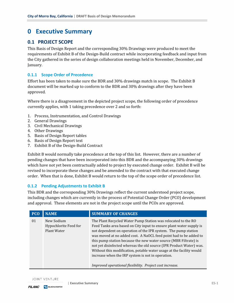
0.1.2 Pending Adjustments to Exhibit B
This BDR and the corresponding 30% Drawings reflect the current understood project scope,
including changes which are currently in the process of Potential Change Order (PCO) development
and approval. These elements are not in the project scope until the PCOs are approved.
PCO NAME SUMMARY OF CHANGES
01 New Sodium
Hypochlorite Feed for
Plant Water
The Plant Recycled Water Pump Station was relocated to the RO
Feed Tanks area based on City input to ensure plant water supply is
not dependent on operation of the IPR system. The pump station
was moved at no added cost. A NaOCL feed point had to be added to
this pump station because the new water source (MBR Filtrate) is
not yet disinfected whereas the old source (IPR Product Water) was.
Without this modification, potable water usage at the facility would
increase when the IRP system is not in operation.
Improved operational flexibility. Project cost increase.
DRAFT Basis of Design Memorandum | City of Morro Bay, California
ES-2 Executive Summary | May 2019
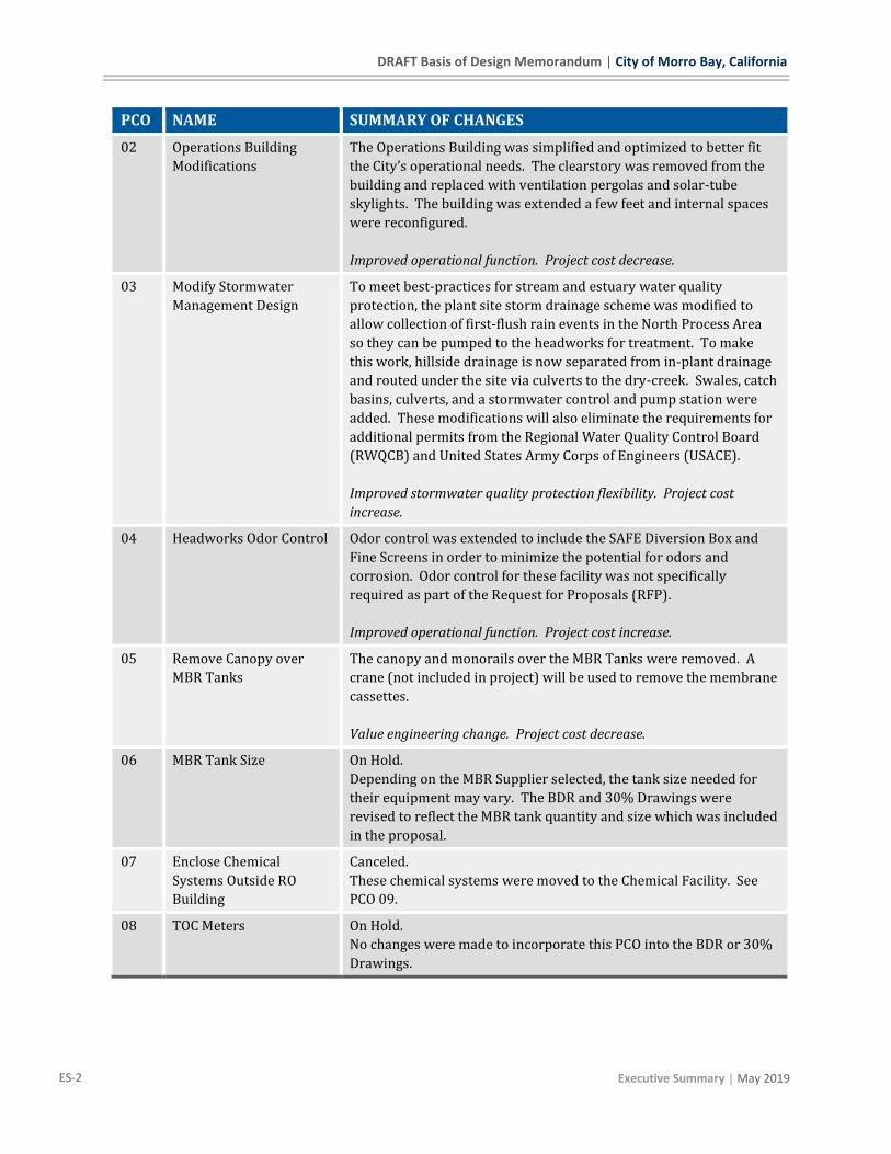
PCO NAME SUMMARY OF CHANGES
02 Operations Building
Modifications
The Operations Building was simplified and optimized to better fit
the City’s operational needs. The clearstory was removed from the
building and replaced with ventilation pergolas and solar-tube
skylights. The building was extended a few feet and internal spaces
were reconfigured.
Improved operational function. Project cost decrease.
03 Modify Stormwater
Management Design
To meet best-practices for stream and estuary water quality
protection, the plant site storm drainage scheme was modified to
allow collection of first-flush rain events in the North Process Area
so they can be pumped to the headworks for treatment. To make
this work, hillside drainage is now separated from in-plant drainage
and routed under the site via culverts to the dry-creek. Swales, catch
basins, culverts, and a stormwater control and pump station were
added. These modifications will also eliminate the requirements for
additional permits from the Regional Water Quality Control Board
(RWQCB) and United States Army Corps of Engineers (USACE).
Improved stormwater quality protection flexibility. Project cost
increase.
04 Headworks Odor Control Odor control was extended to include the SAFE Diversion Box and
Fine Screens in order to minimize the potential for odors and
corrosion. Odor control for these facility was not specifically
required as part of the Request for Proposals (RFP).
Improved operational function. Project cost increase.
05 Remove Canopy over
MBR Tanks
The canopy and monorails over the MBR Tanks were removed. A
crane (not included in project) will be used to remove the membrane
cassettes.
Value engineering change. Project cost decrease.
06 MBR Tank Size On Hold.
Depending on the MBR Supplier selected, the tank size needed for
their equipment may vary. The BDR and 30% Drawings were
revised to reflect the MBR tank quantity and size which was included
in the proposal.
07 Enclose Chemical
Systems Outside RO
Building
Canceled.
These chemical systems were moved to the Chemical Facility. See
PCO 09.
08 TOC Meters On Hold.
No changes were made to incorporate this PCO into the BDR or 30%
Drawings.

City of Morro Bay, California | DRAFT Basis of Design Memorandum
| Executive Summary ES-3
PCO NAME SUMMARY OF CHANGES
09 Consolidate Chemical
Facilities
The chemical facilities outside the RO/UV Building and at the MBR
Area were incorporated into the Chemical Facility. The Chemical
Facility was enlarged and moved to make this function properly.
These modifications were made to improve operator safety and site
security. Chemical facilities located in multiple locations throughout
the facility would also require a more complex hazardous materials
management plan.
Space and spares for a future Liquid Ammonium Sulfate feed system
were also added to this facility per City request.
A Sulfuric Acid feed system was also added, refer to PCO 32.
Improved operational flexibility. Project cost increase.
10 Chemical Piping The chemical piping was changed from double-contained rigid
piping to flexible tubes in concrete-encased PVC ductbanks.
Value engineering change. Project cost decrease.
11 Enclose Dewatering
Equipment
PCO Canceled. See PCO 28.
12 Move Vactor Washdown
Area
The Vactor Washdown Area was moved.
Improved operations. No cost change.
13 Wind Protection at
Headworks
PCO Canceled. See PCO 25.
14 Bypass Line for UV Off-
Spec Water
PCO Canceled.
An automated bypass was added at no cost to allow shunting of off-
spec UV effluent to the Outfall Pump Station, rather than stop
process flow as originally included.
15 Remove Solids Dumpster
Lid
The solids dumpster enclosing lid and curtains were removed and
replaced with an extension of the Dewatering Area Canopy. The
modification was made to reduce operational complexity and
maintenance requirements.
Simplified operations. Project cost increase.
16 Modify Outfall Pump
Station
On hold.
A fourth Outfall Pump was added to provide a spare pump at peak
flow conditions per design review comment. Currently this PCO is
on hold and the pumping configuration will be finalized as design
develops on the Outfall Transmission Pipeline.
DRAFT Basis of Design Memorandum | City of Morro Bay, California
ES-4 Executive Summary | May 2019
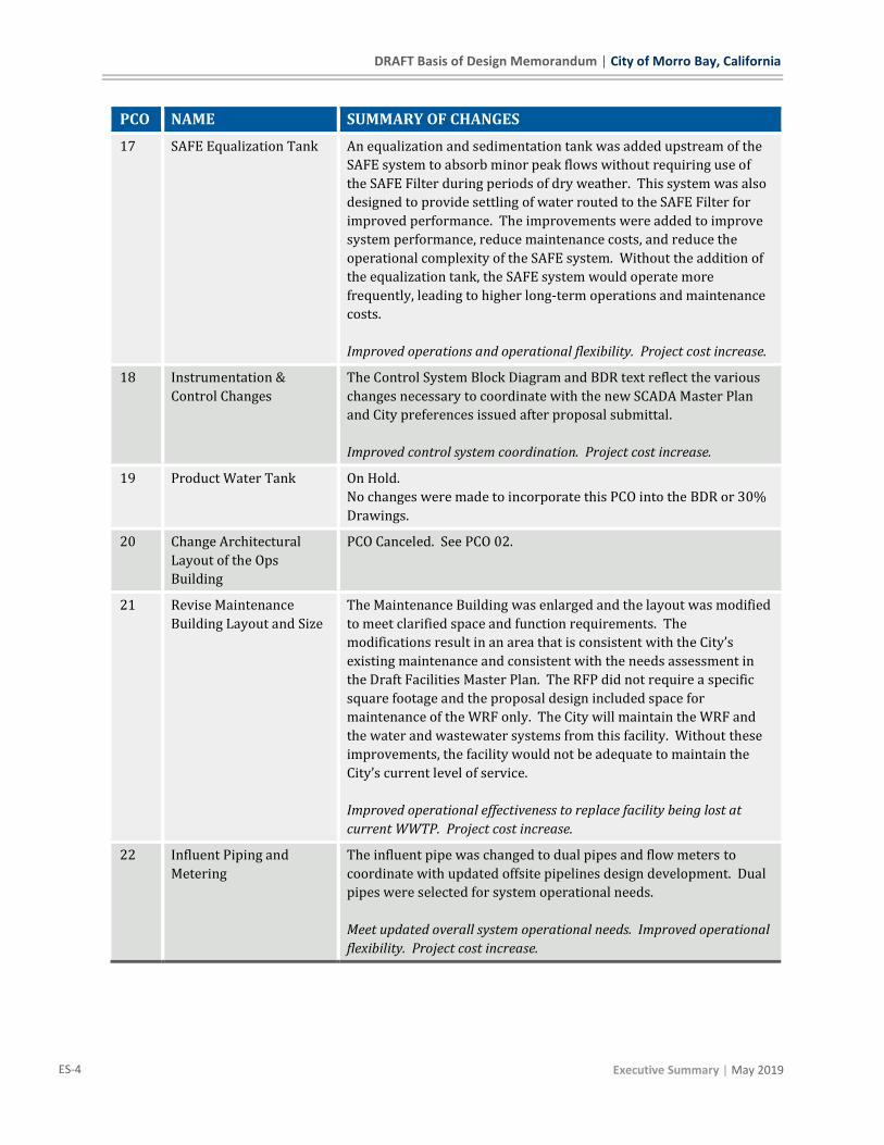
PCO NAME SUMMARY OF CHANGES
17 SAFE Equalization Tank An equalization and sedimentation tank was added upstream of the
SAFE system to absorb minor peak flows without requiring use of
the SAFE Filter during periods of dry weather. This system was also
designed to provide settling of water routed to the SAFE Filter for
improved performance. The improvements were added to improve
system performance, reduce maintenance costs, and reduce the
operational complexity of the SAFE system. Without the addition of
the equalization tank, the SAFE system would operate more
frequently, leading to higher long-term operations and maintenance
costs.
Improved operations and operational flexibility. Project cost increase.
18 Instrumentation &
Control Changes
The Control System Block Diagram and BDR text reflect the various
changes necessary to coordinate with the new SCADA Master Plan
and City preferences issued after proposal submittal.
Improved control system coordination. Project cost increase.
19 Product Water Tank On Hold.
No changes were made to incorporate this PCO into the BDR or 30%
Drawings.
20 Change Architectural
Layout of the Ops
Building
PCO Canceled. See PCO 02.
21 Revise Maintenance
Building Layout and Size
The Maintenance Building was enlarged and the layout was modified
to meet clarified space and function requirements. The
modifications result in an area that is consistent with the City’s
existing maintenance and consistent with the needs assessment in
the Draft Facilities Master Plan. The RFP did not require a specific
square footage and the proposal design included space for
maintenance of the WRF only. The City will maintain the WRF and
the water and wastewater systems from this facility. Without these
improvements, the facility would not be adequate to maintain the
City’s current level of service.
Improved operational effectiveness to replace facility being lost at
current WWTP. Project cost increase.
22 Influent Piping and
Metering
The influent pipe was changed to dual pipes and flow meters to
coordinate with updated offsite pipelines design development. Dual
pipes were selected for system operational needs.
Meet updated overall system operational needs. Improved operational
flexibility. Project cost increase.

City of Morro Bay, California | DRAFT Basis of Design Memorandum
| Executive Summary ES-5
PCO NAME SUMMARY OF CHANGES
23 Install Outdoor-Rated PD
Blowers at BNR Facility
The BNR Aeration Blowers were changed to dry-screw blowers to
address concerns with dust in the seals of the turbo blowers
required by the RFP.
Improved equipment reliability. Project cost decrease.
24 Remove Bypass of Coarse
Screens
The bypass around the Packaged Headworks Units (coarse screens
and grit removal) was removed.
Value engineering change. Project cost decrease.
25 Add Bagging Sleeves at
Headworks
Specialized weighted protection sleeves were added to prevent wind
from blowing and pulling out waste bagging sleeves.
Improved maintenance. No cost change.
26 SAFE Diversion Box
Additions
A removable cover that can be walked on, access ladder, and
handrailing were added to the SAFE Diversion Box to facilitate odor
control (added by PCO 04) and provide for inspection/servicing of
the diversion box while covered.
Improved operations. Project cost increase.
27 Relocate SAFE Facility PCO Canceled.
The SAFE Filter was moved. This PCO was canceled and any costs
associated with moving the SAFE Filter were incorporated into PCO
17.
28 Size Dewatering Area for
Future Enclosure
The Dewatering Area was reconfigured to facilitate future enclosure
of the area without causing issues with equipment access, etc. The
area was rearranged to optimize operation. Note: The canopy
structure and foundation are not designed for walls to be added to it.
Improved long term flexibility. Improved operation. Project cost
increase.
29 10k CY of Additional
Spoils Disposal
On Hold.
The spoils disposal area was enlarged to accommodate up to 10,000
cubic-yards of suitable offsite spoils generated by the conveyance
project. The area shown herein is conceptual, requires modification
of the plant parcel limits, and will require design workshop
discussion to determine a final configuration.
30 Match Sludge Blowers to
BNR Blowers
On Hold.
No changes were made to incorporate this PCO into the BDR or 30%
Drawings.
DRAFT Basis of Design Memorandum | City of Morro Bay, California
ES-6 Executive Summary | May 2019
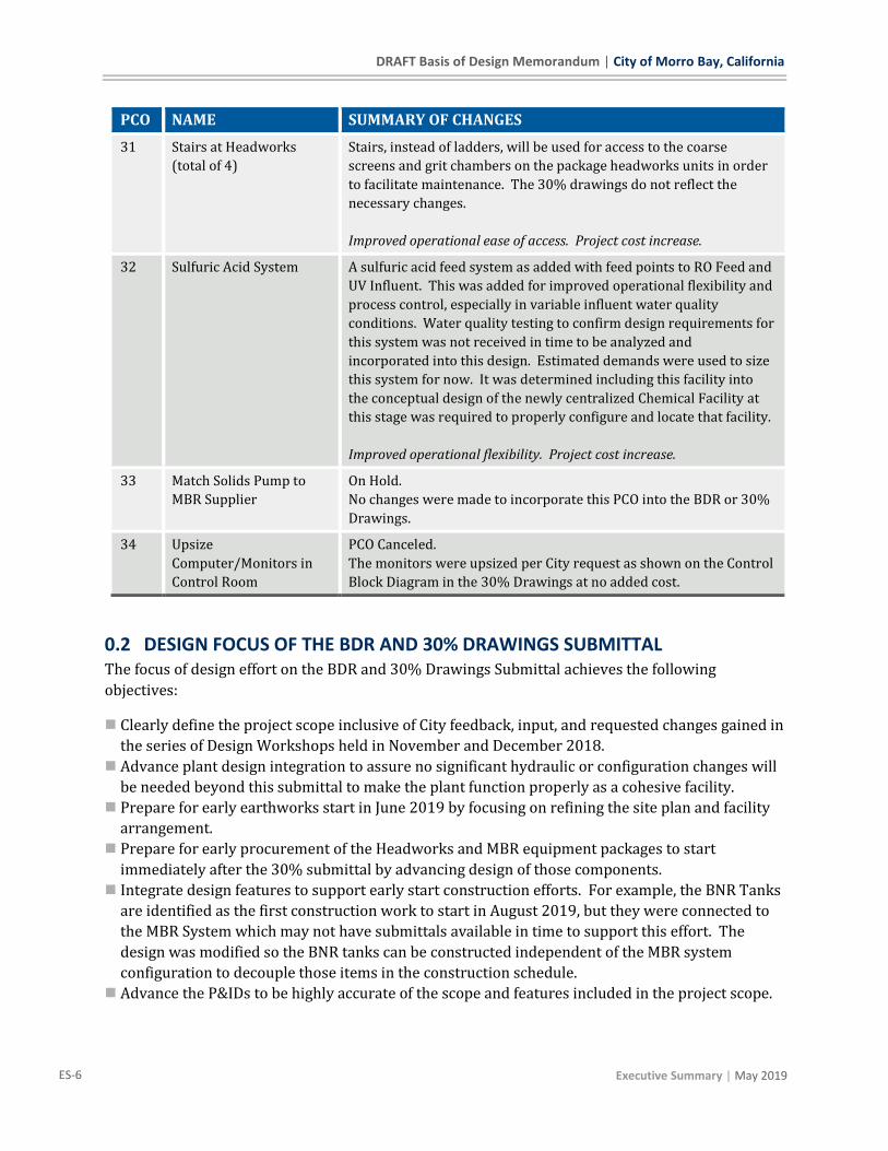
PCO NAME SUMMARY OF CHANGES
31 Stairs at Headworks
(total of 4)
Stairs, instead of ladders, will be used for access to the coarse
screens and grit chambers on the package headworks units in order
to facilitate maintenance. The 30% drawings do not reflect the
necessary changes.
Improved operational ease of access. Project cost increase.
32 Sulfuric Acid System A sulfuric acid feed system as added with feed points to RO Feed and
UV Influent. This was added for improved operational flexibility and
process control, especially in variable influent water quality
conditions. Water quality testing to confirm design requirements for
this system was not received in time to be analyzed and
incorporated into this design. Estimated demands were used to size
this system for now. It was determined including this facility into
the conceptual design of the newly centralized Chemical Facility at
this stage was required to properly configure and locate that facility.
Improved operational flexibility. Project cost increase.
33 Match Solids Pump to
MBR Supplier
On Hold.
No changes were made to incorporate this PCO into the BDR or 30%
Drawings.
34 Upsize
Computer/Monitors in
Control Room
PCO Canceled.
The monitors were upsized per City request as shown on the Control
Block Diagram in the 30% Drawings at no added cost.
0.2 DESIGN FOCUS OF THE BDR AND 30% DRAWINGS SUBMITTAL The focus of design effort on the BDR and 30% Drawings Submittal achieves the following
objectives:
◼ Clearly define the project scope inclusive of City feedback, input, and requested changes gained in
the series of Design Workshops held in November and December 2018.
◼ Advance plant design integration to assure no significant hydraulic or configuration changes will
be needed beyond this submittal to make the plant function properly as a cohesive facility.
◼ Prepare for early earthworks start in June 2019 by focusing on refining the site plan and facility
arrangement.
◼ Prepare for early procurement of the Headworks and MBR equipment packages to start
immediately after the 30% submittal by advancing design of those components.
◼ Integrate design features to support early start construction efforts. For example, the BNR Tanks
are identified as the first construction work to start in August 2019, but they were connected to
the MBR System which may not have submittals available in time to support this effort. The
design was modified so the BNR tanks can be constructed independent of the MBR system
configuration to decouple those items in the construction schedule.
◼ Advance the P&IDs to be highly accurate of the scope and features included in the project scope.

City of Morro Bay, California | DRAFT Basis of Design Memorandum
| Executive Summary ES-7
0.3 DESIGN DEVELOPMENT EFFORTS IN PROGRESS
0.3.1 Anticipated Corrections for Next Submittal
The following issues with this set are known and will be addressed prior to the next submittal:
◼ The legends and abbreviations in the General Drawings have not be conformed to the drawings.
◼ The drawing list font is too small.
◼ The Operations Building outline shown on the Civil Drawings does not quite match the current
layout as shown on the Architectural Drawings.
◼ The MBR Tanks location in the MBR Area shown on the Civil Drawings does not match the
revised location as shown correction on the Civil-Mechanical Drawings. The BNR/MBR Footprint
is accurate on the Civil Drawings.
◼ The 3D Renderings of some facilities show large spread footings. Foundations have not yet been
designed and these footings will be revised in 60% design.
◼ The legends for the P&IDs have not been conformed to the Drawings, but the process codes and
pipe codes have been.
◼ Analyzers: Care was taken to make sure the required analyzers are included in the correct
locations, however, the depiction of the analyzer mounting type (submersible probe, insertion
probe, or flow-thru instrument) is not consistently accurately shown. Analyzer panels may be
collected differently and furnished appurtenances such as valves, rotameters, and flow-by lines
are not consistently shown accurately.
0.3.2 Design Efforts on Hold
The following design efforts are on hold for the reasons stated below:
◼ The Outfall Pump Station design is on hold pending further design coordination with the Outfall
Transmission Pipeline designer.
◼ The IPR Product Water Pump Station design is on hold pending further design coordination with
the IPR Transmission Pipeline designer and design/function requirements development for the
IPR Wellfield Injection system by that designer.
◼ The IPR Product Water Storage Tank design is on hold pending further development of the IPR
Wellfield Injection systems volume and operational requirements by that designer.
◼ The design of the spoils area is on hold pending design workshop discussion on impacts of
accommodating off-site spoils and options for placement, including potential modifications to
plant parcel limits.
◼ Sulfuric Acid Feed System design is on hold pending receipt and analysis of additional water
quality data and design workshop discussion on the results of that analysis.
◼ Vactor Unloading Area design is on hold pending receipt of pictures of facilities the City would
like to emulate.
◼ Design advancement of the Operations and Maintenance Buildings beyond what is included in
the 30% Drawings is on hold pending City review and direction.
0.3.3 Design Efforts in Progress
Beyond normal design progression of the project, the following items are noted as requiring further
design development:

DRAFT Basis of Design Memorandum | City of Morro Bay, California
ES-8 Executive Summary | May 2019
◼ The plant Recycled Water System design will be further developed and refined in detailed design
as specific water demands and scenarios are identified.
◼ The plant Sewer System and Lift Stations will be further developed and refined in detailed design
as specific water and drainage flow volumes and scenarios are identified.
◼ The detailed stormwater calculations and system design are currently in progress. Facilities
shown in this submittal are conceptual.
◼ Design workshop effort focusing on the design of the Water Vehicles Equipment Storage,
Collection Vehicles Equipment Storage, Water Supply Storage, Collection Supply Storage, and
Outdoor Storage Aisles will be performed.
Design layout of the Dechlorination Station will be developed and reviewed in a design review
workshop.

City of Morro Bay, California | DRAFT Basis of Design Memorandum
| Project Overview 1-1
1 Project Overview
1.1 PROJECT BACKGROUND AND DRIVERS In January 2013, the California Coastal Commission (CCC) voted to deny the Coastal Development
Permit (CDP) for construction of upgrading the Morro Bay-Cayucos Wastewater Treatment Plant
(WWTP) at its existing location. The basis for denial included inconsistency with the Local Coastal
Plan’s zoning provisions, failure to avoid coastal hazards, failure to include a sizable reclaimed
water component and project location within an LCP-designated sensitive view area.
One of the drivers for replacing the existing WWTP is the need for a major upgrade in order to meet
the regulatory requirements of the Federal Clean Water Act (CWA) and additional requirements
defined by the State of California Regional Water Quality Control Board (RWQCB). The other key
driver is the California Coastal Commission’s January 2013 direction to relocate the facility to a
more inland area that is consistent with Coastal Act policies.
The CWA defines the quality of treated wastewater that can be released to the environment. In the
case of the City, its treated wastewater is discharged to the Pacific Ocean, offshore and north of
Morro Rock. The existing plant cannot meet state and federal requirements for discharge to the
ocean without significant upgrades. Regional Water Quality Control Board has required the City of
Morro Bay to develop a new treatment facility by 2021.
The City has decided to move forward with construction of a new Water Reclamation Facility
(WRF) that will turn the City’s wastewater into a new, sustainable water source. By expanding its
water supply portfolio to include locally-generated recycled water, the WRF will ultimately improve
the City’s water supply reliability and make the City less reliant on expensive and potentially
uncertain imported water.
1.2 PROJECT DESCRIPTION The City of Morro Bay WRF will be designed to treat an annual average flow of 0.97 million gallons
per day (MGD) of wastewater through full advanced treatment. The WRF will provide preliminary,
secondary, tertiary, and advanced treatment, and will produce recycled water meeting indirect
potable reuse (IPR) standards for a groundwater replenishment reuse project (GRRP) using
subsurface application, as defined in California Code of Regulations (CCR) Title 22 recycled water
requirements. The WRF will be located at the South Bay Boulevard (SBB) site. IPR recycled water
will be conveyed to injection wells in the Morro Valley (conveyance and injection infrastructure by
others). An effluent pipeline (by others) will convey advanced treatment waste streams, including
brine, to the existing Morro Bay Cayucos Sanitary District (MBCSD) jointly-owned ocean outfall at
the site of the existing wastewater treatment plant (WWTP).
A new lift station (by others) near the existing WWTP will convey raw wastewater through a force
main (by others) to the WRF. The WRF, access road to the WRF, and all design and construction
within the South Bay Boulevard (SBB) site and adjacent area north of Highway 1 right-of-way
(ROW) are collectively referred to herein as the WRF Onsite Improvements Project (Project).

DRAFT Basis of Design Memorandum | City of Morro Bay, California
1-2 Project Overview | May 2019
1.3 APPLICABLE CODES AND DESIGN GUIDELINES Where applicable, specific codes and standards are presented in the following sections for each
discipline.
1.4 LIST OF TERMS, ACRONYMS, AND ABBREVIATIONS BNR Biological Nutrient Removal
CCC California Coastal Commission
CDP Coastal Development Permit
CCR California Code of Regulations
CWA Clean Water Act
DDW Division of Drinking Water
GPM gallons per minute
GRRP groundwater replenishment reuse project
IPR Indirect Potable Reuse
MBR Membrane Bio-Reactor
MGD million gallons per day
RO Reverse Osmosis
ROW Right of way
RWQCB Regional Water Quality Control Board
SAFE Stormwater Adaptive Filtration System
SBB South Bay Boulevard
UV Ultraviolet (Ultraviolet Disinfection)
UVAOP Ultraviolet Advanced Oxidation Process
WRF Water Reclamation Facility
WWTP Wastewater Treatment Plant
1.5 JURISDICTIONAL AGENCIES The following are the Jurisdictional Agencies for the Project:
◼ City of Morro Bay
◼ San Luis Obispo County
◼ California Regional Water Quality Control Board (RWQCB)
◼ California Division of Drinking Water (DDW)
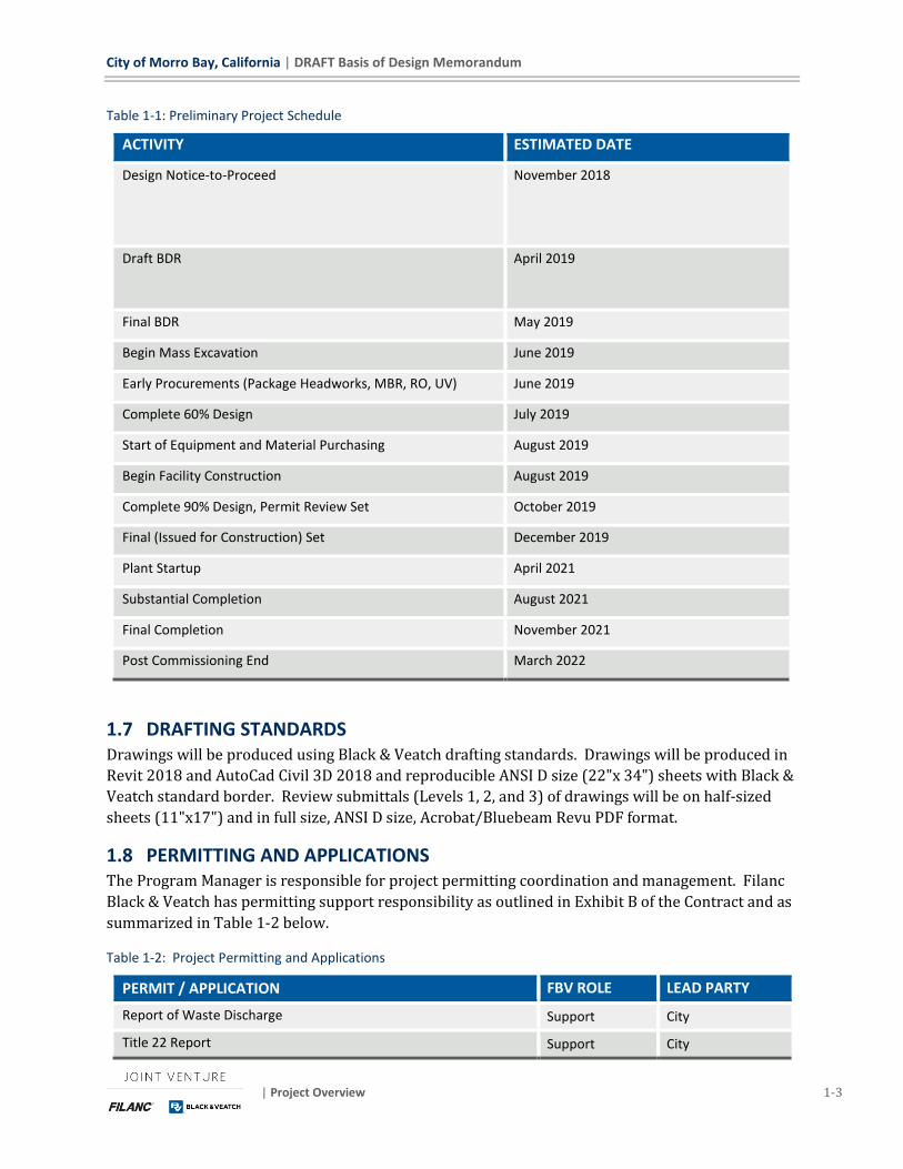
1.6 PROJECT SCHEDULE The proposed preliminary project schedule is shown in Table 1-1 below.
The duration of construction, from Notice to Proceed to Substantial Completion (full operation), is
approximately 33 months.
City of Morro Bay, California | DRAFT Basis of Design Memorandum
| Project Overview 1-3
Table 1-1: Preliminary Project Schedule
ACTIVITY ESTIMATED DATE
Design Notice-to-Proceed
November 2018
Draft BDR
April 2019
Final BDR May 2019
Begin Mass Excavation June 2019
Early Procurements (Package Headworks, MBR, RO, UV) June 2019
Complete 60% Design July 2019
Start of Equipment and Material Purchasing August 2019
Begin Facility Construction August 2019
Complete 90% Design, Permit Review Set October 2019
Final (Issued for Construction) Set December 2019
Plant Startup April 2021
Substantial Completion August 2021
Final Completion November 2021
Post Commissioning End March 2022
1.7 DRAFTING STANDARDS Drawings will be produced using Black & Veatch drafting standards. Drawings will be produced in
Revit 2018 and AutoCad Civil 3D 2018 and reproducible ANSI D size (22"x 34") sheets with Black &
Veatch standard border. Review submittals (Levels 1, 2, and 3) of drawings will be on half-sized
sheets (11"x17") and in full size, ANSI D size, Acrobat/Bluebeam Revu PDF format.
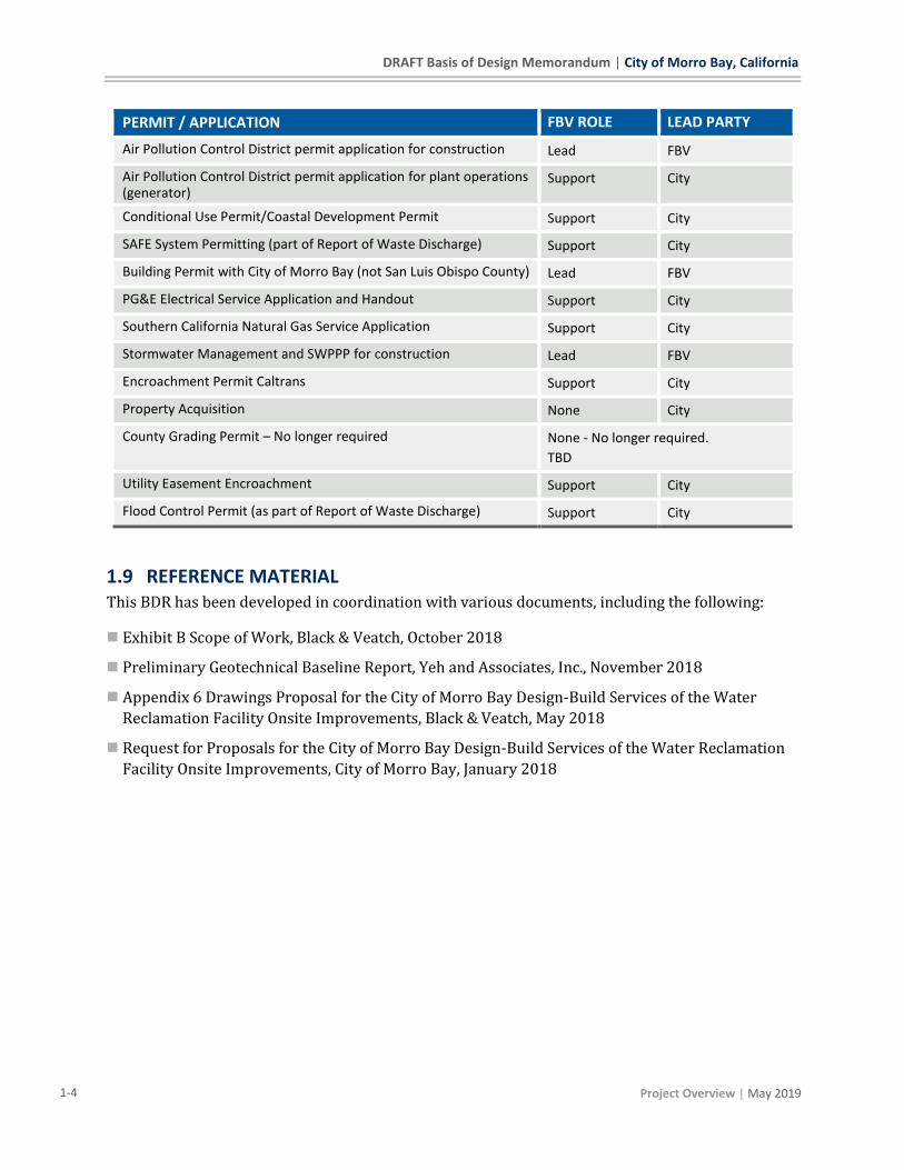
1.8 PERMITTING AND APPLICATIONS The Program Manager is responsible for project permitting coordination and management. Filanc
Black & Veatch has permitting support responsibility as outlined in Exhibit B of the Contract and as
summarized in Table 1-2 below.
Table 1-2: Project Permitting and Applications
PERMIT / APPLICATION FBV ROLE LEAD PARTY
Report of Waste Discharge Support City
Title 22 Report Support City
DRAFT Basis of Design Memorandum | City of Morro Bay, California
1-4 Project Overview | May 2019
PERMIT / APPLICATION FBV ROLE LEAD PARTY
Air Pollution Control District permit application for construction Lead FBV
Air Pollution Control District permit application for plant operations (generator)
Support City
Conditional Use Permit/Coastal Development Permit Support City
SAFE System Permitting (part of Report of Waste Discharge) Support City
Building Permit with City of Morro Bay (not San Luis Obispo County) Lead FBV
PG&E Electrical Service Application and Handout Support City
Southern California Natural Gas Service Application Support City
Stormwater Management and SWPPP for construction Lead FBV
Encroachment Permit Caltrans Support City
Property Acquisition None City
County Grading Permit – No longer required None - No longer required.
TBD
Utility Easement Encroachment Support City
Flood Control Permit (as part of Report of Waste Discharge) Support City
1.9 REFERENCE MATERIAL This BDR has been developed in coordination with various documents, including the following:
◼ Exhibit B Scope of Work, Black & Veatch, October 2018
◼ Preliminary Geotechnical Baseline Report, Yeh and Associates, Inc., November 2018
◼ Appendix 6 Drawings Proposal for the City of Morro Bay Design-Build Services of the Water
Reclamation Facility Onsite Improvements, Black & Veatch, May 2018
◼ Request for Proposals for the City of Morro Bay Design-Build Services of the Water Reclamation
Facility Onsite Improvements, City of Morro Bay, January 2018

City of Morro Bay, California | DRAFT Basis of Design Memorandum
| Existing Information 2-1
2 Existing Information This section discusses existing information for the Morro Bay Water Reclamation Facility (WRF)
and the new site.
2.1 WRF SITE INFORMATION The WRF site is located in unincorporated San Luis Obispo County north of Highway 1 at the
northern terminus of South Bay Boulevard. It is a greenfield site that will be purchased by the City
of Morro Bay from multiple property owners and annexed into City limits.
2.2 PROJECT DATUM, PROJECT BENCHMARKS, SURVEY CONTROL AND LOCAL FLOOD LEVELS
The project survey is in State Plane Coordinate System (NAD83) California Zone V, US foot. The
project benchmark is NGS PID FV1098: brass cap stamped "J 693 Reset 1968" set in concrete,
elevation = 151.79. The survey control will be verified and shown on the drawings.
The new WRF site is classified as Zone X, Area of Minimal Flood Hazard, according to the FEMA
flood maps.
2.3 EXISTING WASTEWATER TREATMENT PLANT The existing Morro Bay-Cayucos Wastewater Treatment Plant (WWTP) was originally constructed
in 1953 with subsequent expansions in 1964 and 1982. The plant currently has an ADWF rating of
2 mgd though the secondary treatment facilities are only rated at 1 mgd. Flow in excess of 1 mgd
requires bypassing of a portion of the primary effluent and blending with disinfected secondary
effluent prior to discharge to an ocean outfall.
The existing WWTP site is located at 160 Atascadero Road in Morro Bay. The site is approximately
300 feet north of Morro Creek.
Upon substantial completion of the new WRF, the old WWTP will be demolished. This work is not
currently in the scope of the WRF project, but a bid-alternate price was furnished should the City
choose to incorporate it into the WRF project. The Cayucos Sanitary District is currently
constructing their own facility off Toro Creek Road.
2.4 EXISTING UTILITIES Existing utilities within the WRF plant parcel include a the Chorro Valley Pipeline of the State Water
Project as well as a PG&E overhead high voltage transmission line. Both of these utilities are
located at the southern end of the WRF plant parcel. These two utility locations are illustrated on
the drawings.
There are additional utilities located outside of the WRF plant parcel, in the vicinity of Teresa Road.
These utilities include a potable water main, natural gas pipe, and city sewer. These utilities are
being confirmed and will be added to the drawings after the 30% set. This project includes
connection of the plant entrance road in this area, and potential minor modifications to the Cal
Trans Highway 1 offramps which will require detailed coordination of these existing utilities.

DRAFT Basis of Design Memorandum | City of Morro Bay, California
2-2 Existing Information | May 2019
2.5 GEOTECHNICAL INFORMATION A preliminary geotechnical baseline report was prepared by Yeh and Associates, Inc. in November
2017. This baseline report provided preliminary geotechnical and geologic conditions, including
baseline groundwater characteristics, soil characteristics, rock characteristics, geotechnical
performance criteria for design, and construction considerations. This baseline report was based on
ten test pits, nine borings, and five seismic refraction lines that were included during a geophysical
survey. Additional geotechnical information is provided in the Structural & Geotechnical Design
Criteria Section.
The geotechnical baseline report by Yeh and Associates, Inc. is used as the basis for design in this
BDR and the 30% drawings. Filanc Black & Veatch is in the process of having an updated
geotechnical report developed to confirm and supplement these findings for detailed design. Any
changes identified in that report which may impact project design will be identified to the City for
discussion and confirmation.

City of Morro Bay, California | DRAFT Basis of Design Memorandum
| Process Design Criteria 3-1
3 Process Design Criteria The WRF shall be designed to receive and treat the full influent wastewater flows from the City of
Morro Bay in accordance with the effluent requirements described in this section.
An update of the plant influent water quality, and evaluation of any design impacts associated with
changed quality values, is on hold pending further data from the City.
The criteria contained herein, and used as the basis of design for the WRF, was developed in the
proposal phase based the wastewater quality data furnished by the City with the RFP. This data did
not contain many of the constituents important to RO and UVAOP system designs. To develop this
data, the City’s potable water data was used and factored up based on potable to wastewater
concentration factors seen at other typical facilities, such as at the Santa Clara Valley Water District
Silicon Valley Advanced Water Purification Center.
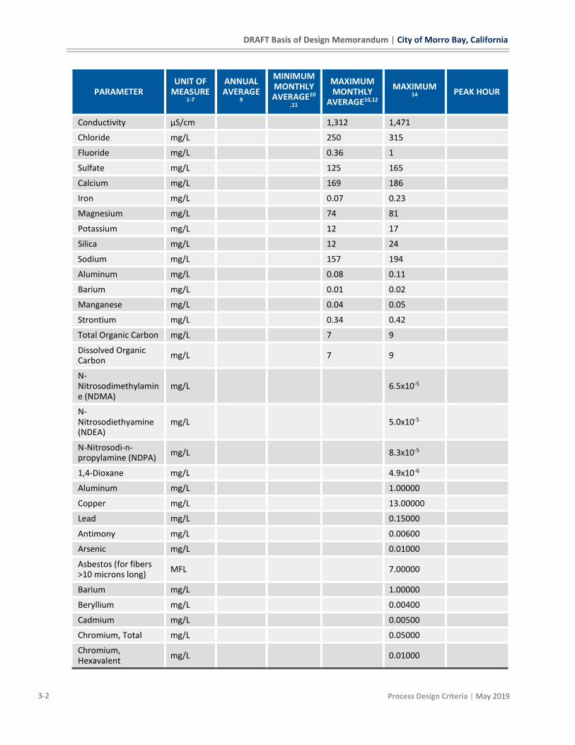
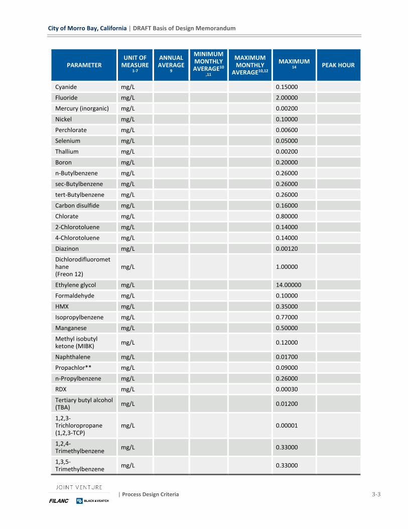
Table 3-1 provides the influent annual average, minimum monthly average, maximum monthly
average, maximum and peak hour flows. It also provides all corresponding water quality data.
Table 3-1: Influent Loads and Water Quality
PARAMETER UNIT OF
MEASURE1-7
ANNUAL AVERAGE
9
MINIMUM MONTHLY AVERAGE10
,11
MAXIMUM MONTHLY
AVERAGE10,12
MAXIMUM 14
PEAK HOUR
Flow MGD 0.97 1.16 2.74 8.14
BOD5 mg/L 354 374
lb/d 2,864 3,618 4,845
TSS mg/L 392 437
lb/d 3,171 4,228 6,193
TKN mg-N/L 57 60
lb-N/d 461 580 777
NHx-N mg-N/L 46 48
lb-N/d 369 464 622
Total Phosphorus mg-P/L 6 8
lb-P/d 49 77 183
Ortho Phosphorus mg-P/L 4 5
lb-P/d 32 48 114
Total Fats, Oils and Grease
mg/L 80 90 120
Free Oils mg/L 1 1 1
Mineral or Non-Biodegradable Oils
mg/L 5 5 5
pH S.U range: 6.7 - 8.5
Temperature °C 20 17
Total Dissolved Solids
mg/L 920 1,029
DRAFT Basis of Design Memorandum | City of Morro Bay, California
3-2 Process Design Criteria | May 2019
PARAMETER UNIT OF
MEASURE1-7
ANNUAL AVERAGE
9
MINIMUM MONTHLY AVERAGE10
,11
MAXIMUM MONTHLY
AVERAGE10,12
MAXIMUM 14
PEAK HOUR
Conductivity µS/cm 1,312 1,471
Chloride mg/L 250 315
Fluoride mg/L 0.36 1
Sulfate mg/L 125 165
Calcium mg/L 169 186
Iron mg/L 0.07 0.23
Magnesium mg/L 74 81
Potassium mg/L 12 17
Silica mg/L 12 24
Sodium mg/L 157 194
Aluminum mg/L 0.08 0.11
Barium mg/L 0.01 0.02
Manganese mg/L 0.04 0.05
Strontium mg/L 0.34 0.42
Total Organic Carbon mg/L 7 9
Dissolved Organic Carbon
mg/L 7 9
N-Nitrosodimethylamine (NDMA)
mg/L 6.5x10⁻⁵
N-Nitrosodiethyamine (NDEA)
mg/L 5.0x10⁻⁵
N-Nitrosodi-n-propylamine (NDPA)
mg/L 8.3x10⁻⁵
1,4-Dioxane mg/L 4.9x10⁻⁶
Aluminum mg/L 1.00000
Copper mg/L 13.00000
Lead mg/L 0.15000
Antimony mg/L 0.00600
Arsenic mg/L 0.01000
Asbestos (for fibers >10 microns long)
MFL 7.00000
Barium mg/L 1.00000
Beryllium mg/L 0.00400
Cadmium mg/L 0.00500
Chromium, Total mg/L 0.05000
Chromium, Hexavalent
mg/L 0.01000
City of Morro Bay, California | DRAFT Basis of Design Memorandum
| Process Design Criteria 3-3
PARAMETER UNIT OF
MEASURE1-7
ANNUAL AVERAGE
9
MINIMUM MONTHLY AVERAGE10
,11
MAXIMUM MONTHLY
AVERAGE10,12
MAXIMUM 14
PEAK HOUR
Cyanide mg/L 0.15000
Fluoride mg/L 2.00000
Mercury (inorganic) mg/L 0.00200
Nickel mg/L 0.10000
Perchlorate mg/L 0.00600
Selenium mg/L 0.05000
Thallium mg/L 0.00200
Boron mg/L 0.20000
n-Butylbenzene mg/L 0.26000
sec-Butylbenzene mg/L 0.26000
tert-Butylbenzene mg/L 0.26000
Carbon disulfide mg/L 0.16000
Chlorate mg/L 0.80000
2-Chlorotoluene mg/L 0.14000
4-Chlorotoluene mg/L 0.14000
Diazinon mg/L 0.00120
Dichlorodifluoromethane (Freon 12)
mg/L 1.00000
Ethylene glycol mg/L 14.00000
Formaldehyde mg/L 0.10000
HMX mg/L 0.35000
Isopropylbenzene mg/L 0.77000
Manganese mg/L 0.50000
Methyl isobutyl ketone (MIBK)
mg/L 0.12000
Naphthalene mg/L 0.01700
Propachlor** mg/L 0.09000
n-Propylbenzene mg/L 0.26000
RDX mg/L 0.00030
Tertiary butyl alcohol (TBA)
mg/L 0.01200
1,2,3-Trichloropropane (1,2,3-TCP)
mg/L 0.00001
1,2,4-Trimethylbenzene
mg/L 0.33000
1,3,5-Trimethylbenzene
mg/L 0.33000

DRAFT Basis of Design Memorandum | City of Morro Bay, California
3-4 Process Design Criteria | May 2019
PARAMETER UNIT OF
MEASURE1-7
ANNUAL AVERAGE
9
MINIMUM MONTHLY AVERAGE10
,11
MAXIMUM MONTHLY
AVERAGE10,12
MAXIMUM 14
PEAK HOUR
2,4,6-Trinitrotoluene (TNT)
mg/L 0.00100
Vanadium mg/L 0.05000
Alachlor mg/L 0.00200
Atrazine mg/L 0.00100
Bentazon mg/L 0.01800
Benzo(a)pyrene mg/L 0.00020
Carbofuran mg/L 0.01800
Chlordane mg/L 0.00010
Dalapon mg/L 0.20000
1,2-Dibromo-3-chloropropane (DBCP)
mg/L 0.00020
2,4-Dichlorophenoxyacetic acid (2,4-D)
mg/L 0.07000
Di(2-ethylhexyl)adipate
mg/L 0.40000
Di(2-ethylhexyl)phthalate (DEHP)
mg/L 0.00400
Dinoseb mg/L 0.00700
Diquat mg/L 0.02000
Endrin mg/L 0.00200
Endothal mg/L 0.10000
Ethylene dibromide (EDB)
mg/L 0.00005
Glyphosate mg/L 0.70000
Heptachlor mg/L 0.00001
Heptachlor epoxide mg/L 0.00001
Hexachlorobenzene mg/L 0.00100
Hexachlorocyclopentadiene
mg/L 0.05000
Lindane mg/L 0.00020
Methoxychlor mg/L 0.03000
Molinate mg/L 0.02000
Oxamyl mg/L 0.05000
Pentachlorophenol mg/L 0.00100
Picloram mg/L 0.50000
City of Morro Bay, California | DRAFT Basis of Design Memorandum
| Process Design Criteria 3-5
PARAMETER UNIT OF
MEASURE1-7
ANNUAL AVERAGE
9
MINIMUM MONTHLY AVERAGE10
,11
MAXIMUM MONTHLY
AVERAGE10,12
MAXIMUM 14
PEAK HOUR
Polychlorinated biphenyls (PCBs)
mg/L 0.00050
Simazine mg/L 0.00400
2,4,5-TP (Silvex) mg/L 0.05000
2,3,7,8-TCDD (dioxin) mg/L 3x10⁻⁸
Thiobencarb mg/L 0.07000
Toxaphene mg/L 0.00300
Total Trihalomethanes
mg/L 0.08000
Bromodichloromethane
mg/L 0.0010
Bromoform mg/L 0.0010
Chloroform mg/L 0.0010
Dibromochloromethane
mg/L 0.0010
Haloacetic Acids (five) (HAA5)
mg/L 0.06000
Monochloroacetic Acid
mg/L 0.0020
Dichloroacetic Adic
mg/L 0.0010
Trichloroacetic Acid
mg/L 0.0010
Monobromoacetic Acid
mg/L 0.0010
Dibromoacetic Acid
mg/L 0.0010
Bromate mg/L 0.01000
Chlorite mg/L 1.00000
Gross alpha particle activity
pCi/L 15.00000
Gross beta particle activity
pCi/L 4.00000
Radium-226 pCi/L 0.05000
Radium-228 pCi/L 0.01900
Radium-226 + Radium-228
pCi/L 5.00000
Strontium-90 pCi/L 8.00000
Tritium pCi/L 20,000
DRAFT Basis of Design Memorandum | City of Morro Bay, California
3-6 Process Design Criteria | May 2019
PARAMETER UNIT OF
MEASURE1-7
ANNUAL AVERAGE
9
MINIMUM MONTHLY AVERAGE10
,11
MAXIMUM MONTHLY
AVERAGE10,12
MAXIMUM 14
PEAK HOUR
Uranium pCi/L 20.00
Benzene mg/L 0.001
Carbon tetrachloride mg/L 0.0005
1,2-Dichlorobenzene mg/L 0.6
1,4-Dichlorobenzene (p-DCB)
mg/L 0.005
1,1-Dichloroethane (1,1-DCA)
mg/L 0.005
1,2-Dichloroethane (1,2-DCA)
mg/L 0.0005
1,1-Dichloroethylene (1,1-DCE)
mg/L 0.006
cis-1,2-Dichloroethylene
mg/L 0.006
trans-1,2-Dichloroethylene
mg/L 0.01
Dichloromethane (Methylene chloride)
mg/L 0.005
1,2-Dichloropropane mg/L 0.005
1,3-Dichloropropene mg/L 0.0005
Ethylbenzene mg/L 0.3
Methyl tertiary butyl ether (MTBE)
mg/L 0.013
Monochlorobenzene mg/L 0.07
Styrene mg/L 0.1
1,1,2,2-Tetrachloroethane
mg/L 0.001
Tetrachloroethylene (PCE)
mg/L 0.005
Toluene mg/L 0.15
1,2,4-Trichlorobenzene
mg/L 0.005
1,1,1-Trichloroethane (1,1,1-TCA)
mg/L 0.2
1,1,2-Trichloroethane (1,1,2-TCA)
mg/L 0.005
Trichloroethylene (TCE)
mg/L 0.005

City of Morro Bay, California | DRAFT Basis of Design Memorandum
| Process Design Criteria 3-7
PARAMETER UNIT OF
MEASURE1-7
ANNUAL AVERAGE
9
MINIMUM MONTHLY AVERAGE10
,11
MAXIMUM MONTHLY
AVERAGE10,12
MAXIMUM 14
PEAK HOUR
Trichlorofluoromethane (Freon 11)
mg/L 0.15
1,1,2-Trichloro-1,2,2-Trifluoroethane (Freon 113)
mg/L 1.2
Vinyl chloride mg/L 0.0005
Xylenes mg/L 1.75
Footnotes:
1. Flow units: MGD = million gallons per day
2. Concentration units: mg/L = milligrams per liter; mg-N/L = milligrams per liter as Nitrogen; mg-P/L = milligrams per liter as Phosphorus
3. Mass Load Units: lb/d = pounds per day (calculated using on concentration and flow); lb-N/d = pounds nitrogen per day; lb-P/d = pounds phosphorus per day.
4. S.U. = standard units 5. °C = degrees centigrade 6. µS/cm = microsiemens per centimeter 7. pCi/L = picocuries per liter 8. Influent samples shall be collected as composite samples. A composite sample is a flow-
weighted combination of no fewer than eight (8) individual samples obtained at equal time intervals over a 24-hour period. The volume of each individual sample collected is proportional to the flowrate at the time of sampling.
9. Annual average is the arithmetic average of the total number of data collected in a calendar year.
10. The monthly average is the arithmetic mean of the daily concentrations over a calendar month. 11. Minimum Monthly Average is the minimum value of the monthly average in a calendar year. 12. Maximum Monthly Average is the maximum value of the monthly average in a calendar year. 13. Maximum day flow and load incorporates a maximum day flow and a maximum day load. The
maximum day flow is the maximum daily total flow in a calendar year. The maximum day load for a particular parameter is the largest amount received in the influent during a continuous 24-hour period expressed as a weight per day.
14. Maximum is the maximum concentration value of any composite sample in a calendar year.
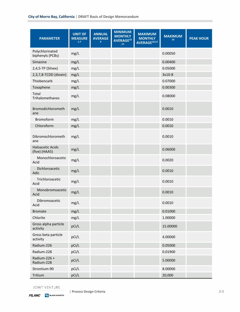
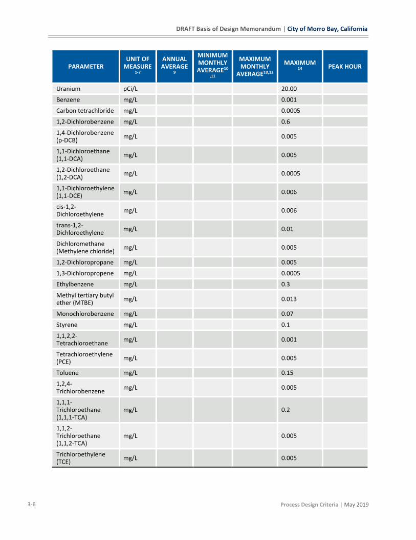
3.1 EFFLUENT QUALITY REQUIREMENTS This section summarizes the effluent quality requirements for the project.
3.1.1 Ocean Discharge Requirements
The effluent from the WRF discharged to the Ocean will meet the requirements for Effluent
Limitations – Discharge Point No. 001 set forth in National Pollution Discharge Elimination System

DRAFT Basis of Design Memorandum | City of Morro Bay, California
3-8 Process Design Criteria | May 2019
(NPDES) No. CA0047881, Draft Order No. R3-2017-0050 adopted by the Central Coast Water Board
on December 7, 2017 with compliance measured utilizing the effluent composite sample collected
at the Morro Bay WRF site.
3.1.2 Potable Reuse Requirements
Finished water quality for the new potable reuse facility will meet all Maximum Contaminant Level
(MCL) and secondary MCL values found in SWRCB (2015) and notification level (NL) requirements
from the State of California
(https://www.waterboards.ca.gov/drinking_water/certlic/drinkingwater/documents/notificationl
evels/notification_levels_response_levels_overview.pdf)
Table 3-2 illustrates the target log removal credits for the WRF.
Table 3-2: Log Removal Performance Expectations
PATHOGEN DDW REQUIREMENT
MBR RO UV-AOP
FREE CHLORINE
UNDERGROUND RETENTION
TOTAL WRF
Virus 12 1 1.5(1) 6 4 2 14.5
Giardia 10 2.5 1.5 6 - - 10
Cryptosporidium 10 2.5 1.5 6 - - 10
(1) In consideration of the subsurface travel time and LRV credits offered through the suite of unit operations,
only 1 log virus removal is required through the RO system.
City of Morro Bay, California | DRAFT Basis of Design Memorandum
| Facility Design Criteria 4-1
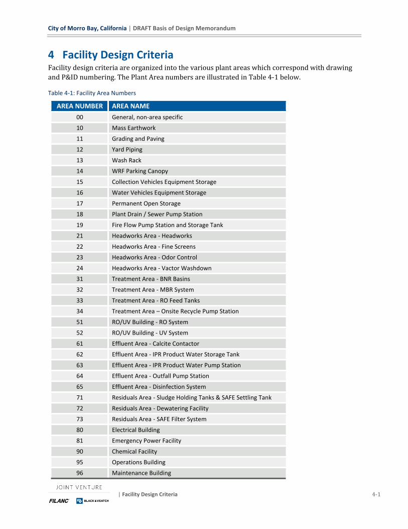
4 Facility Design Criteria Facility design criteria are organized into the various plant areas which correspond with drawing
and P&ID numbering. The Plant Area numbers are illustrated in Table 4-1 below.
Table 4-1: Facility Area Numbers
AREA NUMBER AREA NAME
00 General, non-area specific
10 Mass Earthwork
11 Grading and Paving
12 Yard Piping
13 Wash Rack
14 WRF Parking Canopy
15 Collection Vehicles Equipment Storage
16 Water Vehicles Equipment Storage
17 Permanent Open Storage
18 Plant Drain / Sewer Pump Station
19 Fire Flow Pump Station and Storage Tank
21 Headworks Area - Headworks
22 Headworks Area - Fine Screens
23 Headworks Area - Odor Control
24 Headworks Area - Vactor Washdown
31 Treatment Area - BNR Basins
32 Treatment Area - MBR System
33 Treatment Area - RO Feed Tanks
34 Treatment Area – Onsite Recycle Pump Station
51 RO/UV Building - RO System
52 RO/UV Building - UV System
61 Effluent Area - Calcite Contactor
62 Effluent Area - IPR Product Water Storage Tank
63 Effluent Area - IPR Product Water Pump Station
64 Effluent Area - Outfall Pump Station
65 Effluent Area - Disinfection System
71 Residuals Area - Sludge Holding Tanks & SAFE Settling Tank
72 Residuals Area - Dewatering Facility
73 Residuals Area - SAFE Filter System
80 Electrical Building
81 Emergency Power Facility
90 Chemical Facility
95 Operations Building
96 Maintenance Building
DRAFT Basis of Design Memorandum | City of Morro Bay, California
4-2 Facility Design Criteria | May 2019
4.1 HEADWORKS – AREA 20
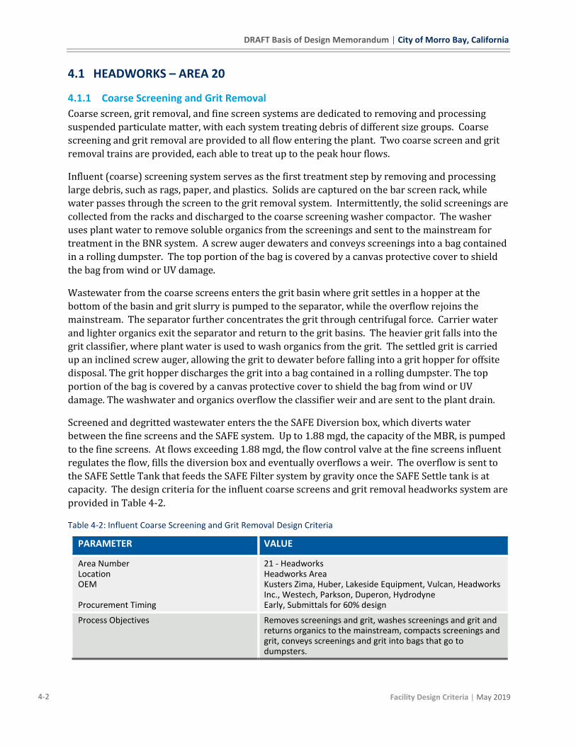
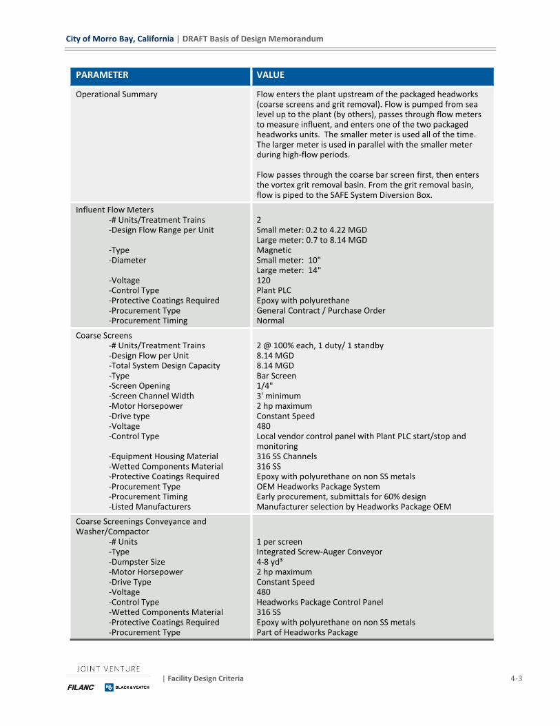
4.1.1 Coarse Screening and Grit Removal
Coarse screen, grit removal, and fine screen systems are dedicated to removing and processing
suspended particulate matter, with each system treating debris of different size groups. Coarse
screening and grit removal are provided to all flow entering the plant. Two coarse screen and grit
removal trains are provided, each able to treat up to the peak hour flows.
Influent (coarse) screening system serves as the first treatment step by removing and processing
large debris, such as rags, paper, and plastics. Solids are captured on the bar screen rack, while
water passes through the screen to the grit removal system. Intermittently, the solid screenings are
collected from the racks and discharged to the coarse screening washer compactor. The washer
uses plant water to remove soluble organics from the screenings and sent to the mainstream for
treatment in the BNR system. A screw auger dewaters and conveys screenings into a bag contained
in a rolling dumpster. The top portion of the bag is covered by a canvas protective cover to shield
the bag from wind or UV damage.
Wastewater from the coarse screens enters the grit basin where grit settles in a hopper at the
bottom of the basin and grit slurry is pumped to the separator, while the overflow rejoins the
mainstream. The separator further concentrates the grit through centrifugal force. Carrier water
and lighter organics exit the separator and return to the grit basins. The heavier grit falls into the
grit classifier, where plant water is used to wash organics from the grit. The settled grit is carried
up an inclined screw auger, allowing the grit to dewater before falling into a grit hopper for offsite
disposal. The grit hopper discharges the grit into a bag contained in a rolling dumpster. The top
portion of the bag is covered by a canvas protective cover to shield the bag from wind or UV
damage. The washwater and organics overflow the classifier weir and are sent to the plant drain.
Screened and degritted wastewater enters the the SAFE Diversion box, which diverts water
between the fine screens and the SAFE system. Up to 1.88 mgd, the capacity of the MBR, is pumped
to the fine screens. At flows exceeding 1.88 mgd, the flow control valve at the fine screens influent
regulates the flow, fills the diversion box and eventually overflows a weir. The overflow is sent to
the SAFE Settle Tank that feeds the SAFE Filter system by gravity once the SAFE Settle tank is at
capacity. The design criteria for the influent coarse screens and grit removal headworks system are
provided in Table 4-2.
Table 4-2: Influent Coarse Screening and Grit Removal Design Criteria
PARAMETER VALUE
Area Number Location OEM Procurement Timing
21 - Headworks Headworks Area Kusters Zima, Huber, Lakeside Equipment, Vulcan, Headworks Inc., Westech, Parkson, Duperon, Hydrodyne Early, Submittals for 60% design
Process Objectives Removes screenings and grit, washes screenings and grit and returns organics to the mainstream, compacts screenings and grit, conveys screenings and grit into bags that go to dumpsters.
City of Morro Bay, California | DRAFT Basis of Design Memorandum
| Facility Design Criteria 4-3
PARAMETER VALUE
Operational Summary Flow enters the plant upstream of the packaged headworks (coarse screens and grit removal). Flow is pumped from sea level up to the plant (by others), passes through flow meters to measure influent, and enters one of the two packaged headworks units. The smaller meter is used all of the time. The larger meter is used in parallel with the smaller meter during high-flow periods. Flow passes through the coarse bar screen first, then enters the vortex grit removal basin. From the grit removal basin, flow is piped to the SAFE System Diversion Box.
Influent Flow Meters -# Units/Treatment Trains -Design Flow Range per Unit -Type -Diameter
-Voltage -Control Type -Protective Coatings Required -Procurement Type -Procurement Timing
2 Small meter: 0.2 to 4.22 MGD Large meter: 0.7 to 8.14 MGD Magnetic Small meter: 10" Large meter: 14" 120 Plant PLC Epoxy with polyurethane General Contract / Purchase Order Normal
Coarse Screens -# Units/Treatment Trains -Design Flow per Unit -Total System Design Capacity -Type -Screen Opening -Screen Channel Width -Motor Horsepower -Drive type -Voltage -Control Type -Equipment Housing Material -Wetted Components Material -Protective Coatings Required -Procurement Type -Procurement Timing -Listed Manufacturers
2 @ 100% each, 1 duty/ 1 standby 8.14 MGD 8.14 MGD Bar Screen 1/4" 3' minimum 2 hp maximum Constant Speed 480 Local vendor control panel with Plant PLC start/stop and monitoring 316 SS Channels 316 SS Epoxy with polyurethane on non SS metals OEM Headworks Package System Early procurement, submittals for 60% design Manufacturer selection by Headworks Package OEM
Coarse Screenings Conveyance and Washer/Compactor
-# Units -Type -Dumpster Size -Motor Horsepower -Drive Type -Voltage -Control Type -Wetted Components Material -Protective Coatings Required -Procurement Type
1 per screen Integrated Screw-Auger Conveyor 4-8 yd³ 2 hp maximum Constant Speed 480 Headworks Package Control Panel 316 SS Epoxy with polyurethane on non SS metals Part of Headworks Package
DRAFT Basis of Design Memorandum | City of Morro Bay, California
4-4 Facility Design Criteria | May 2019
PARAMETER VALUE
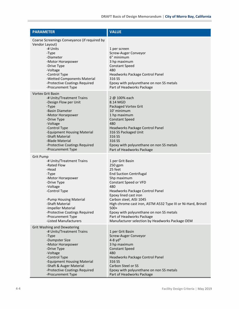
Coarse Screenings Conveyance (if required by Vendor Layout)
-# Units -Type -Diameter -Motor Horsepower -Drive Type -Voltage -Control Type -Wetted Components Material -Protective Coatings Required -Procurement Type
1 per screen Screw-Auger Conveyor 6" minimum 3 hp maximum Constant Speed 480 Headworks Package Control Panel 316 SS Epoxy with polyurethane on non SS metals Part of Headworks Package
Vortex Grit Basin -# Units/Treatment Trains -Design Flow per Unit -Type -Basin Diameter -Motor Horsepower -Drive Type -Voltage -Control Type -Equipment Housing Material -Shaft Material -Blade Material -Protective Coatings Required -Procurement Type
2 @ 100% each 8.14 MGD Packaged Vortex Grit 10' minimum 1 hp maximum Constant Speed 480 Headworks Package Control Panel 316 SS Packaged Unit 316 SS 316 SS Epoxy with polyurethane on non SS metals Part of Headworks Package
Grit Pump -# Units/Treatment Trains -Rated Flow -Head -Type -Motor Horsepower -Drive Type -Voltage -Control Type -Pump Housing Material -Shaft Material -Impeller Material -Protective Coatings Required -Procurement Type -Listed Manufacturers
1 per Grit Basin 250 gpm 25 feet End Suction Centrifugal 5hp maximum Constant Speed or VFD 480 Headworks Package Control Panel Epoxy lined cast iron Carbon steel, AISI 1045 High chrome cast iron, ASTM A532 Type III or Ni-Hard, Brinell 500+ Epoxy with polyurethane on non SS metals Part of Headworks Package Manufacturer selection by Headworks Package OEM
Grit Washing and Dewatering -# Units/Treatment Trains -Type -Dumpster Size -Motor Horsepower -Drive Type -Voltage -Control Type -Equipment Housing Material -Shaft & Auger Material -Protective Coatings Required -Procurement Type
1 per Grit Basin Screw-Auger Conveyor 4-8 yd³ 3 hp maximum Constant Speed 480 Headworks Package Control Panel 316 SS Carbon Steel or SS Epoxy with polyurethane on non SS metals Part of Headworks Package
City of Morro Bay, California | DRAFT Basis of Design Memorandum
| Facility Design Criteria 4-5
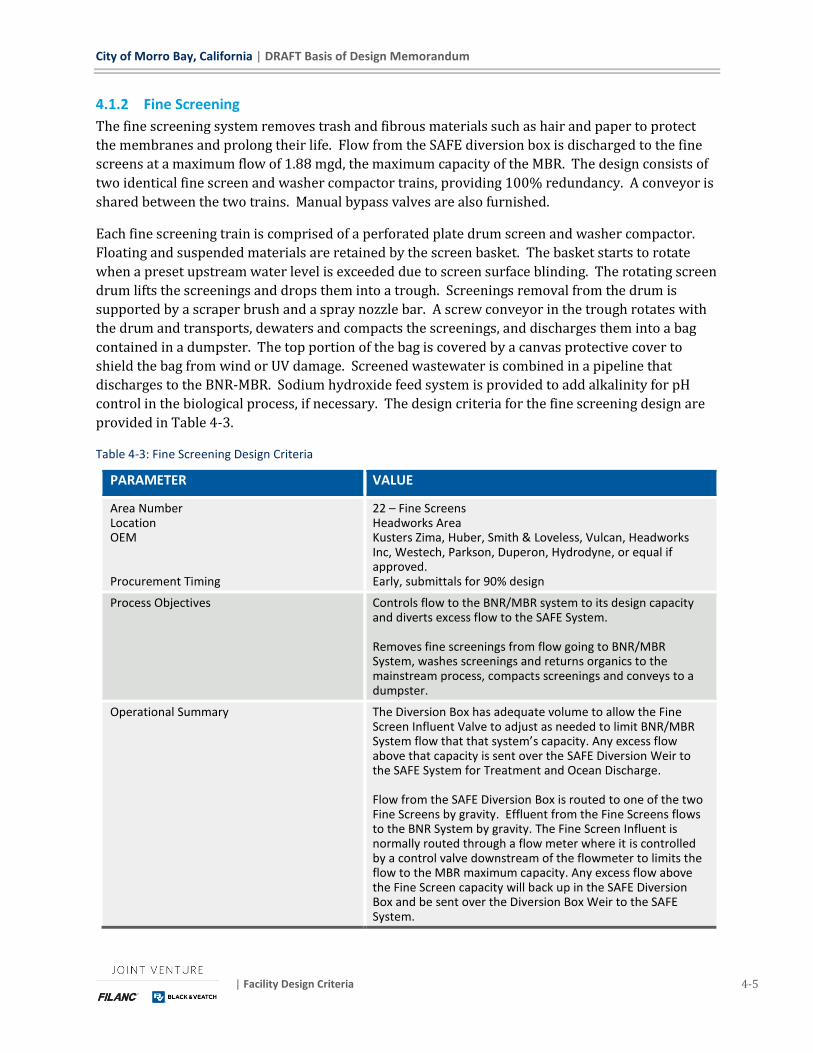
4.1.2 Fine Screening
The fine screening system removes trash and fibrous materials such as hair and paper to protect
the membranes and prolong their life. Flow from the SAFE diversion box is discharged to the fine
screens at a maximum flow of 1.88 mgd, the maximum capacity of the MBR. The design consists of
two identical fine screen and washer compactor trains, providing 100% redundancy. A conveyor is
shared between the two trains. Manual bypass valves are also furnished.
Each fine screening train is comprised of a perforated plate drum screen and washer compactor.
Floating and suspended materials are retained by the screen basket. The basket starts to rotate
when a preset upstream water level is exceeded due to screen surface blinding. The rotating screen
drum lifts the screenings and drops them into a trough. Screenings removal from the drum is
supported by a scraper brush and a spray nozzle bar. A screw conveyor in the trough rotates with
the drum and transports, dewaters and compacts the screenings, and discharges them into a bag
contained in a dumpster. The top portion of the bag is covered by a canvas protective cover to
shield the bag from wind or UV damage. Screened wastewater is combined in a pipeline that
discharges to the BNR-MBR. Sodium hydroxide feed system is provided to add alkalinity for pH
control in the biological process, if necessary. The design criteria for the fine screening design are
provided in Table 4-3.
Table 4-3: Fine Screening Design Criteria
PARAMETER VALUE
Area Number Location OEM Procurement Timing
22 – Fine Screens Headworks Area Kusters Zima, Huber, Smith & Loveless, Vulcan, Headworks Inc, Westech, Parkson, Duperon, Hydrodyne, or equal if approved. Early, submittals for 90% design
Process Objectives Controls flow to the BNR/MBR system to its design capacity and diverts excess flow to the SAFE System. Removes fine screenings from flow going to BNR/MBR System, washes screenings and returns organics to the mainstream process, compacts screenings and conveys to a dumpster.
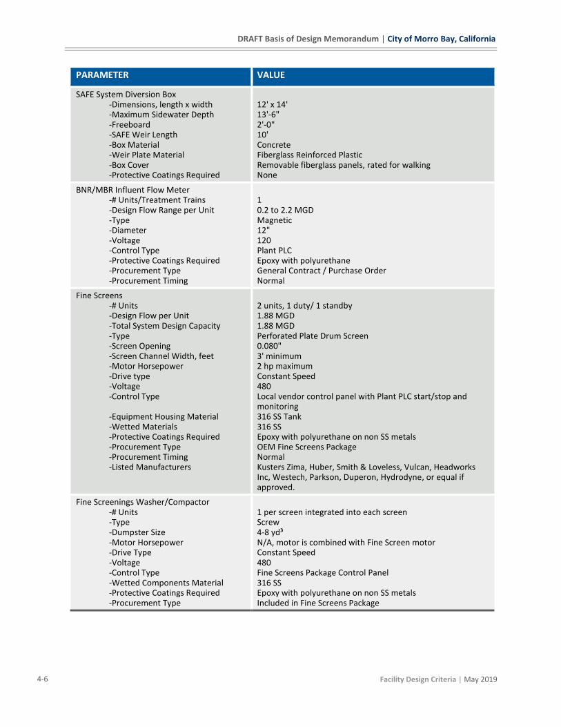
Operational Summary The Diversion Box has adequate volume to allow the Fine Screen Influent Valve to adjust as needed to limit BNR/MBR System flow that that system’s capacity. Any excess flow above that capacity is sent over the SAFE Diversion Weir to the SAFE System for Treatment and Ocean Discharge. Flow from the SAFE Diversion Box is routed to one of the two Fine Screens by gravity. Effluent from the Fine Screens flows to the BNR System by gravity. The Fine Screen Influent is normally routed through a flow meter where it is controlled by a control valve downstream of the flowmeter to limits the flow to the MBR maximum capacity. Any excess flow above the Fine Screen capacity will back up in the SAFE Diversion Box and be sent over the Diversion Box Weir to the SAFE System.
DRAFT Basis of Design Memorandum | City of Morro Bay, California
4-6 Facility Design Criteria | May 2019
PARAMETER VALUE
SAFE System Diversion Box -Dimensions, length x width -Maximum Sidewater Depth -Freeboard -SAFE Weir Length -Box Material -Weir Plate Material -Box Cover -Protective Coatings Required
12' x 14' 13'-6" 2'-0" 10' Concrete Fiberglass Reinforced Plastic Removable fiberglass panels, rated for walking None
BNR/MBR Influent Flow Meter -# Units/Treatment Trains -Design Flow Range per Unit -Type -Diameter -Voltage -Control Type -Protective Coatings Required -Procurement Type -Procurement Timing
1 0.2 to 2.2 MGD Magnetic 12" 120 Plant PLC Epoxy with polyurethane General Contract / Purchase Order Normal
Fine Screens -# Units -Design Flow per Unit -Total System Design Capacity -Type -Screen Opening -Screen Channel Width, feet -Motor Horsepower -Drive type -Voltage -Control Type -Equipment Housing Material -Wetted Materials -Protective Coatings Required -Procurement Type -Procurement Timing -Listed Manufacturers
2 units, 1 duty/ 1 standby 1.88 MGD 1.88 MGD Perforated Plate Drum Screen 0.080" 3' minimum 2 hp maximum Constant Speed 480 Local vendor control panel with Plant PLC start/stop and monitoring 316 SS Tank 316 SS Epoxy with polyurethane on non SS metals OEM Fine Screens Package Normal Kusters Zima, Huber, Smith & Loveless, Vulcan, Headworks Inc, Westech, Parkson, Duperon, Hydrodyne, or equal if approved.
Fine Screenings Washer/Compactor -# Units -Type -Dumpster Size -Motor Horsepower -Drive Type -Voltage -Control Type -Wetted Components Material -Protective Coatings Required -Procurement Type
1 per screen integrated into each screen Screw 4-8 yd³ N/A, motor is combined with Fine Screen motor Constant Speed 480 Fine Screens Package Control Panel 316 SS Epoxy with polyurethane on non SS metals Included in Fine Screens Package
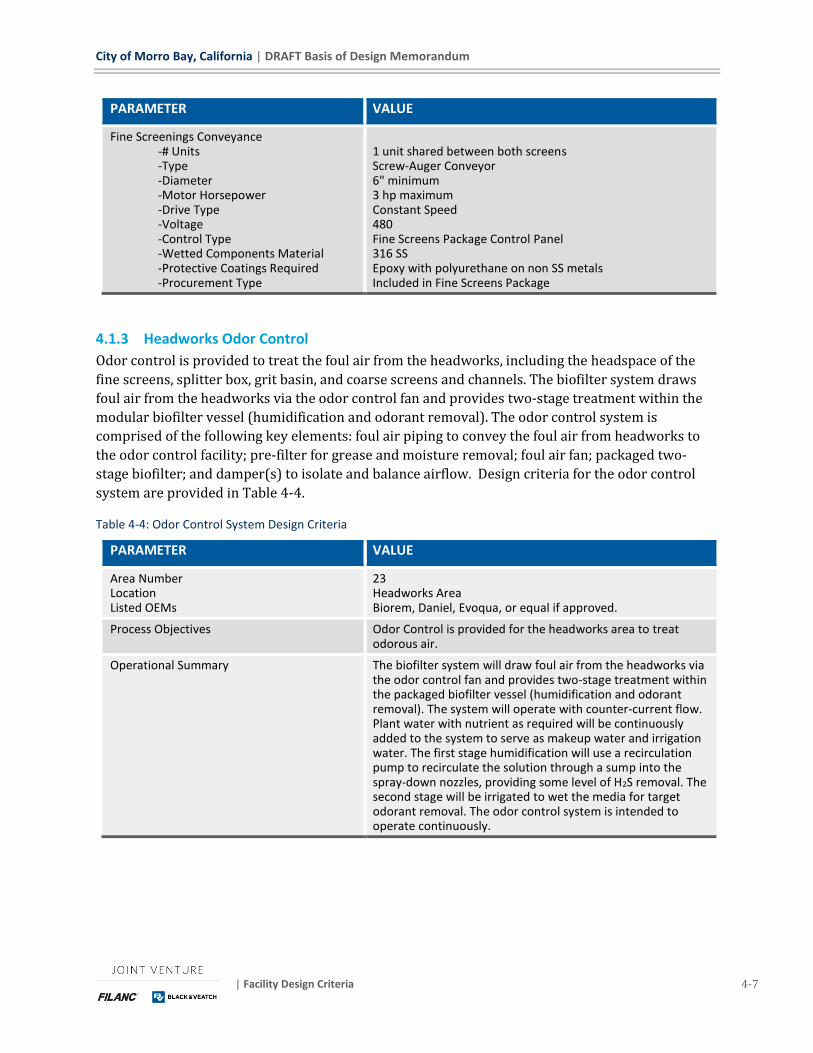
City of Morro Bay, California | DRAFT Basis of Design Memorandum
| Facility Design Criteria 4-7
PARAMETER VALUE
Fine Screenings Conveyance -# Units -Type -Diameter -Motor Horsepower -Drive Type -Voltage -Control Type -Wetted Components Material -Protective Coatings Required -Procurement Type
1 unit shared between both screens Screw-Auger Conveyor 6" minimum 3 hp maximum Constant Speed 480 Fine Screens Package Control Panel 316 SS Epoxy with polyurethane on non SS metals Included in Fine Screens Package
4.1.3 Headworks Odor Control
Odor control is provided to treat the foul air from the headworks, including the headspace of the
fine screens, splitter box, grit basin, and coarse screens and channels. The biofilter system draws
foul air from the headworks via the odor control fan and provides two-stage treatment within the
modular biofilter vessel (humidification and odorant removal). The odor control system is
comprised of the following key elements: foul air piping to convey the foul air from headworks to
the odor control facility; pre-filter for grease and moisture removal; foul air fan; packaged two-
stage biofilter; and damper(s) to isolate and balance airflow. Design criteria for the odor control
system are provided in Table 4-4.
Table 4-4: Odor Control System Design Criteria
PARAMETER VALUE
Area Number Location Listed OEMs
23 Headworks Area Biorem, Daniel, Evoqua, or equal if approved.
Process Objectives Odor Control is provided for the headworks area to treat odorous air.
Operational Summary The biofilter system will draw foul air from the headworks via the odor control fan and provides two-stage treatment within the packaged biofilter vessel (humidification and odorant removal). The system will operate with counter-current flow. Plant water with nutrient as required will be continuously added to the system to serve as makeup water and irrigation water. The first stage humidification will use a recirculation pump to recirculate the solution through a sump into the spray-down nozzles, providing some level of H2S removal. The second stage will be irrigated to wet the media for target odorant removal. The odor control system is intended to operate continuously.
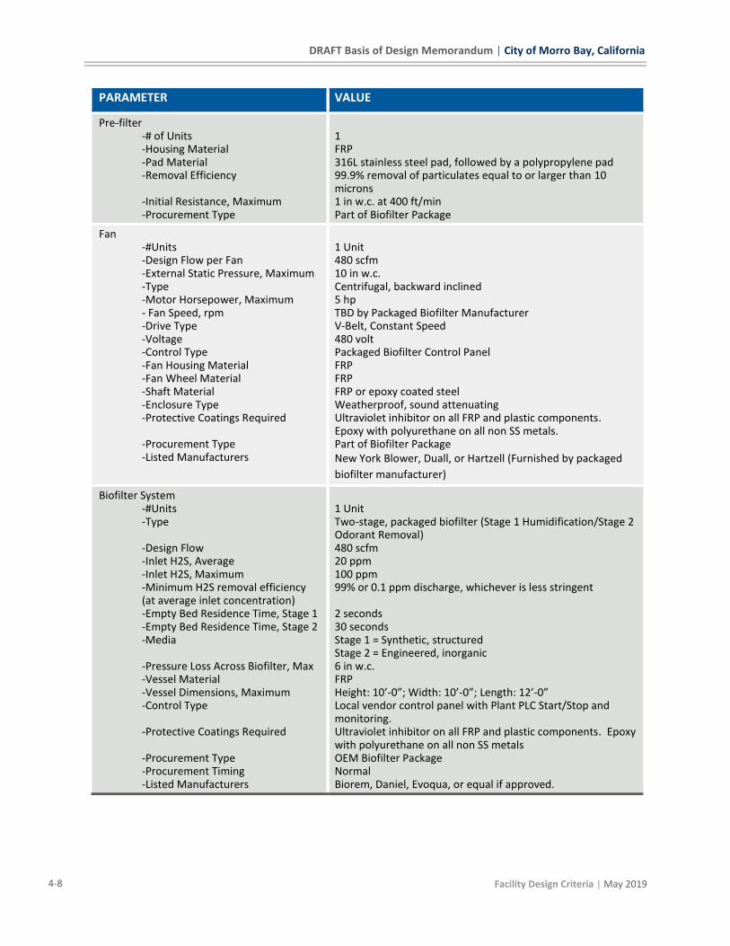
DRAFT Basis of Design Memorandum | City of Morro Bay, California
4-8 Facility Design Criteria | May 2019
PARAMETER VALUE
Pre-filter -# of Units -Housing Material -Pad Material -Removal Efficiency -Initial Resistance, Maximum -Procurement Type
1 FRP 316L stainless steel pad, followed by a polypropylene pad 99.9% removal of particulates equal to or larger than 10 microns 1 in w.c. at 400 ft/min Part of Biofilter Package
Fan -#Units -Design Flow per Fan -External Static Pressure, Maximum -Type -Motor Horsepower, Maximum - Fan Speed, rpm -Drive Type -Voltage -Control Type -Fan Housing Material -Fan Wheel Material -Shaft Material -Enclosure Type -Protective Coatings Required -Procurement Type -Listed Manufacturers
1 Unit 480 scfm 10 in w.c. Centrifugal, backward inclined 5 hp TBD by Packaged Biofilter Manufacturer V-Belt, Constant Speed 480 volt Packaged Biofilter Control Panel FRP FRP FRP or epoxy coated steel Weatherproof, sound attenuating Ultraviolet inhibitor on all FRP and plastic components. Epoxy with polyurethane on all non SS metals. Part of Biofilter Package New York Blower, Duall, or Hartzell (Furnished by packaged
biofilter manufacturer)
Biofilter System -#Units -Type
-Design Flow -Inlet H2S, Average -Inlet H2S, Maximum -Minimum H2S removal efficiency (at average inlet concentration) -Empty Bed Residence Time, Stage 1 -Empty Bed Residence Time, Stage 2 -Media -Pressure Loss Across Biofilter, Max -Vessel Material -Vessel Dimensions, Maximum -Control Type -Protective Coatings Required -Procurement Type -Procurement Timing -Listed Manufacturers
1 Unit Two-stage, packaged biofilter (Stage 1 Humidification/Stage 2 Odorant Removal) 480 scfm 20 ppm 100 ppm 99% or 0.1 ppm discharge, whichever is less stringent 2 seconds 30 seconds Stage 1 = Synthetic, structured Stage 2 = Engineered, inorganic 6 in w.c. FRP Height: 10’-0”; Width: 10’-0”; Length: 12’-0” Local vendor control panel with Plant PLC Start/Stop and monitoring. Ultraviolet inhibitor on all FRP and plastic components. Epoxy with polyurethane on all non SS metals OEM Biofilter Package Normal Biorem, Daniel, Evoqua, or equal if approved.
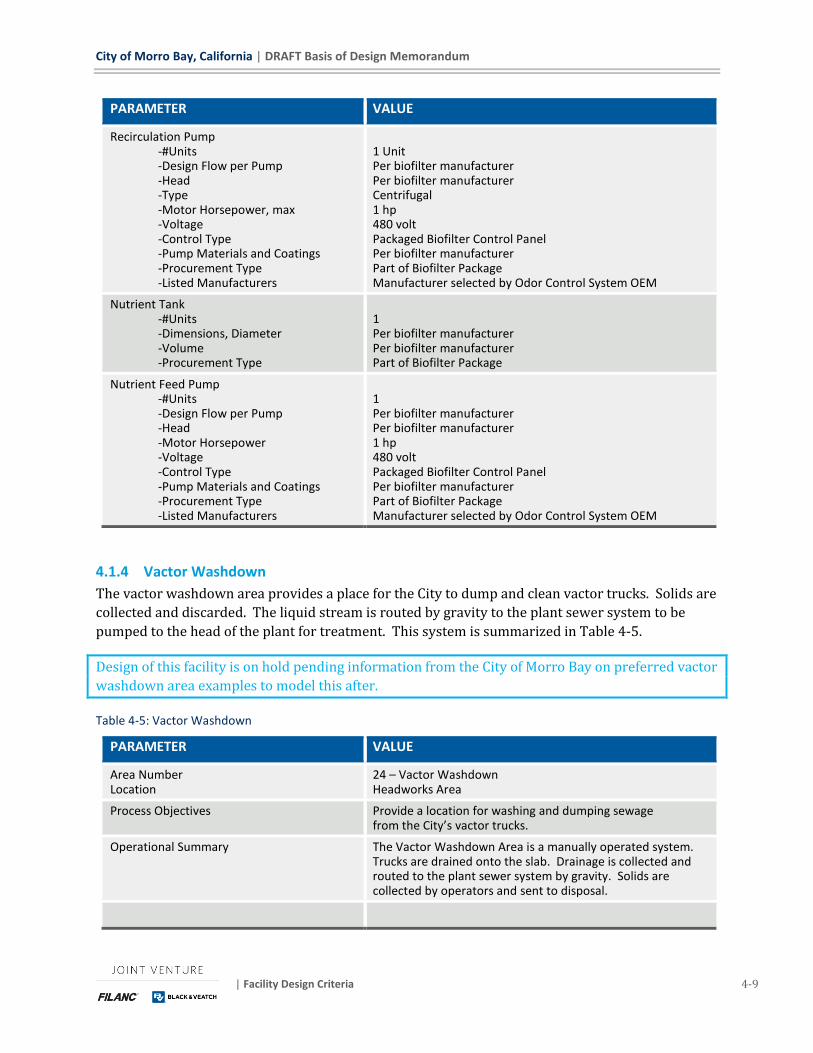
City of Morro Bay, California | DRAFT Basis of Design Memorandum
| Facility Design Criteria 4-9
PARAMETER VALUE
Recirculation Pump -#Units -Design Flow per Pump -Head -Type -Motor Horsepower, max -Voltage -Control Type -Pump Materials and Coatings -Procurement Type -Listed Manufacturers
1 Unit Per biofilter manufacturer Per biofilter manufacturer Centrifugal 1 hp 480 volt Packaged Biofilter Control Panel Per biofilter manufacturer Part of Biofilter Package Manufacturer selected by Odor Control System OEM
Nutrient Tank -#Units -Dimensions, Diameter -Volume -Procurement Type
1 Per biofilter manufacturer Per biofilter manufacturer Part of Biofilter Package
Nutrient Feed Pump -#Units -Design Flow per Pump -Head -Motor Horsepower -Voltage -Control Type -Pump Materials and Coatings -Procurement Type -Listed Manufacturers
1 Per biofilter manufacturer Per biofilter manufacturer 1 hp 480 volt Packaged Biofilter Control Panel Per biofilter manufacturer Part of Biofilter Package Manufacturer selected by Odor Control System OEM
4.1.4 Vactor Washdown
The vactor washdown area provides a place for the City to dump and clean vactor trucks. Solids are
collected and discarded. The liquid stream is routed by gravity to the plant sewer system to be
pumped to the head of the plant for treatment. This system is summarized in Table 4-5.
Design of this facility is on hold pending information from the City of Morro Bay on preferred vactor
washdown area examples to model this after.
Table 4-5: Vactor Washdown
PARAMETER VALUE
Area Number Location
24 – Vactor Washdown Headworks Area
Process Objectives Provide a location for washing and dumping sewage from the City’s vactor trucks.
Operational Summary The Vactor Washdown Area is a manually operated system. Trucks are drained onto the slab. Drainage is collected and routed to the plant sewer system by gravity. Solids are collected by operators and sent to disposal.
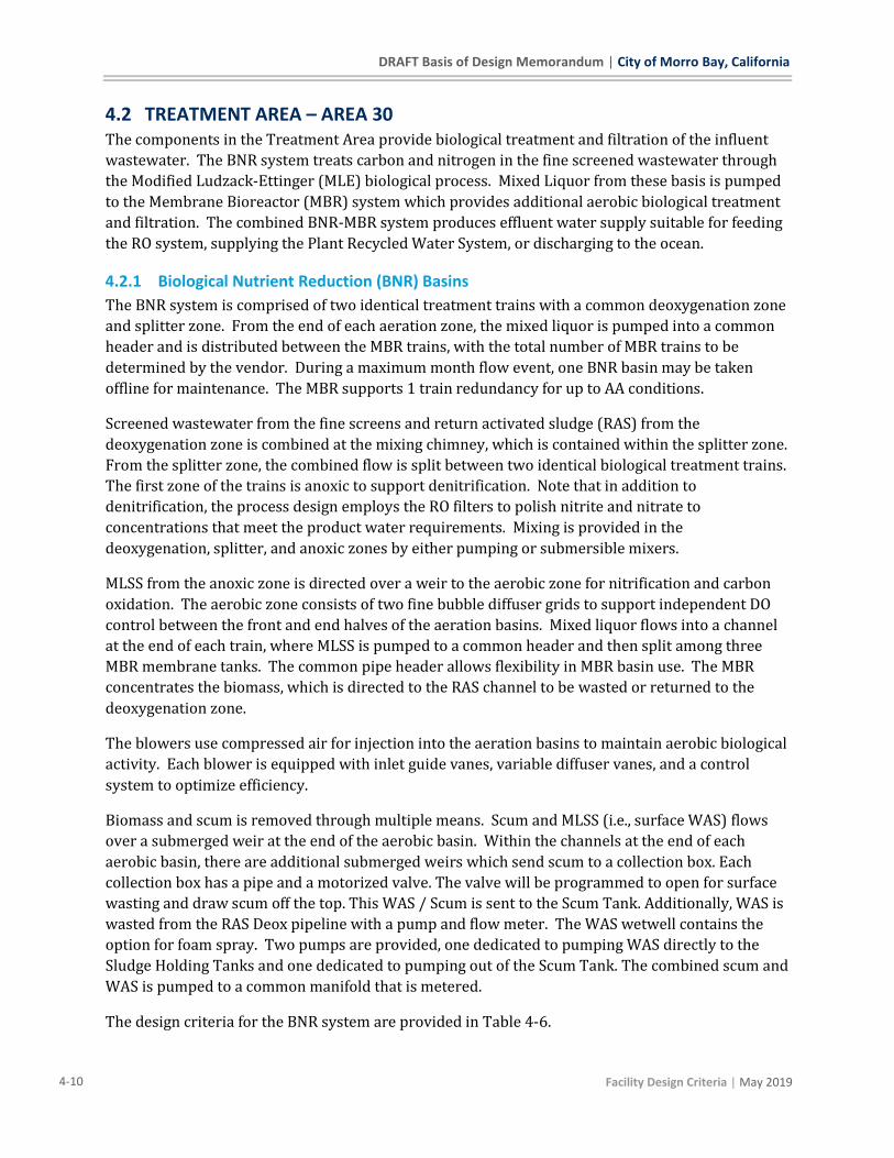
DRAFT Basis of Design Memorandum | City of Morro Bay, California
4-10 Facility Design Criteria | May 2019
4.2 TREATMENT AREA – AREA 30 The components in the Treatment Area provide biological treatment and filtration of the influent
wastewater. The BNR system treats carbon and nitrogen in the fine screened wastewater through
the Modified Ludzack-Ettinger (MLE) biological process. Mixed Liquor from these basis is pumped
to the Membrane Bioreactor (MBR) system which provides additional aerobic biological treatment
and filtration. The combined BNR-MBR system produces effluent water supply suitable for feeding
the RO system, supplying the Plant Recycled Water System, or discharging to the ocean.
4.2.1 Biological Nutrient Reduction (BNR) Basins
The BNR system is comprised of two identical treatment trains with a common deoxygenation zone
and splitter zone. From the end of each aeration zone, the mixed liquor is pumped into a common
header and is distributed between the MBR trains, with the total number of MBR trains to be
determined by the vendor. During a maximum month flow event, one BNR basin may be taken
offline for maintenance. The MBR supports 1 train redundancy for up to AA conditions.
Screened wastewater from the fine screens and return activated sludge (RAS) from the
deoxygenation zone is combined at the mixing chimney, which is contained within the splitter zone.
From the splitter zone, the combined flow is split between two identical biological treatment trains.
The first zone of the trains is anoxic to support denitrification. Note that in addition to
denitrification, the process design employs the RO filters to polish nitrite and nitrate to
concentrations that meet the product water requirements. Mixing is provided in the
deoxygenation, splitter, and anoxic zones by either pumping or submersible mixers.
MLSS from the anoxic zone is directed over a weir to the aerobic zone for nitrification and carbon
oxidation. The aerobic zone consists of two fine bubble diffuser grids to support independent DO
control between the front and end halves of the aeration basins. Mixed liquor flows into a channel
at the end of each train, where MLSS is pumped to a common header and then split among three
MBR membrane tanks. The common pipe header allows flexibility in MBR basin use. The MBR
concentrates the biomass, which is directed to the RAS channel to be wasted or returned to the
deoxygenation zone.
The blowers use compressed air for injection into the aeration basins to maintain aerobic biological
activity. Each blower is equipped with inlet guide vanes, variable diffuser vanes, and a control
system to optimize efficiency.
Biomass and scum is removed through multiple means. Scum and MLSS (i.e., surface WAS) flows
over a submerged weir at the end of the aerobic basin. Within the channels at the end of each
aerobic basin, there are additional submerged weirs which send scum to a collection box. Each
collection box has a pipe and a motorized valve. The valve will be programmed to open for surface
wasting and draw scum off the top. This WAS / Scum is sent to the Scum Tank. Additionally, WAS is
wasted from the RAS Deox pipeline with a pump and flow meter. The WAS wetwell contains the
option for foam spray. Two pumps are provided, one dedicated to pumping WAS directly to the
Sludge Holding Tanks and one dedicated to pumping out of the Scum Tank. The combined scum and
WAS is pumped to a common manifold that is metered.
The design criteria for the BNR system are provided in Table 4-6.
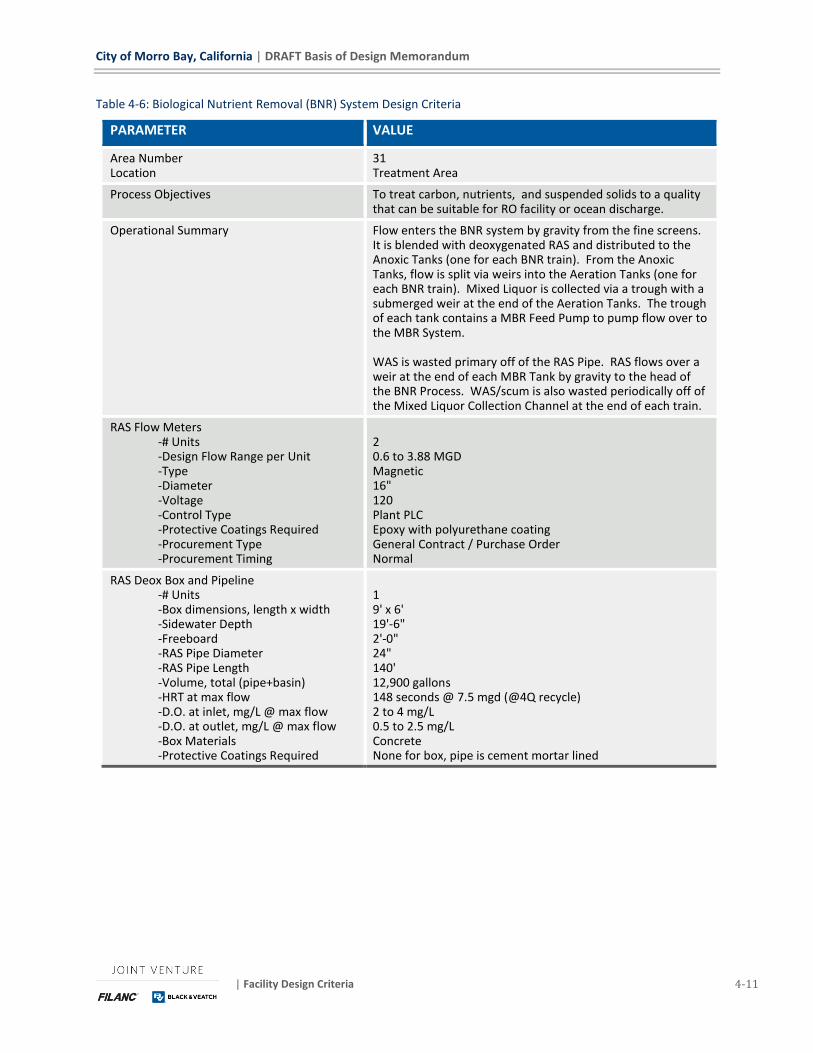
City of Morro Bay, California | DRAFT Basis of Design Memorandum
| Facility Design Criteria 4-11
Table 4-6: Biological Nutrient Removal (BNR) System Design Criteria
PARAMETER VALUE
Area Number Location
31 Treatment Area
Process Objectives To treat carbon, nutrients, and suspended solids to a quality that can be suitable for RO facility or ocean discharge.
Operational Summary Flow enters the BNR system by gravity from the fine screens. It is blended with deoxygenated RAS and distributed to the Anoxic Tanks (one for each BNR train). From the Anoxic Tanks, flow is split via weirs into the Aeration Tanks (one for each BNR train). Mixed Liquor is collected via a trough with a submerged weir at the end of the Aeration Tanks. The trough of each tank contains a MBR Feed Pump to pump flow over to the MBR System. WAS is wasted primary off of the RAS Pipe. RAS flows over a weir at the end of each MBR Tank by gravity to the head of the BNR Process. WAS/scum is also wasted periodically off of the Mixed Liquor Collection Channel at the end of each train.
RAS Flow Meters -# Units -Design Flow Range per Unit -Type -Diameter -Voltage -Control Type -Protective Coatings Required -Procurement Type -Procurement Timing
2 0.6 to 3.88 MGD Magnetic 16" 120 Plant PLC Epoxy with polyurethane coating General Contract / Purchase Order Normal
RAS Deox Box and Pipeline -# Units -Box dimensions, length x width -Sidewater Depth -Freeboard -RAS Pipe Diameter -RAS Pipe Length -Volume, total (pipe+basin) -HRT at max flow -D.O. at inlet, mg/L @ max flow -D.O. at outlet, mg/L @ max flow -Box Materials -Protective Coatings Required
1 9' x 6' 19'-6" 2'-0" 24" 140' 12,900 gallons 148 seconds @ 7.5 mgd (@4Q recycle) 2 to 4 mg/L 0.5 to 2.5 mg/L Concrete None for box, pipe is cement mortar lined
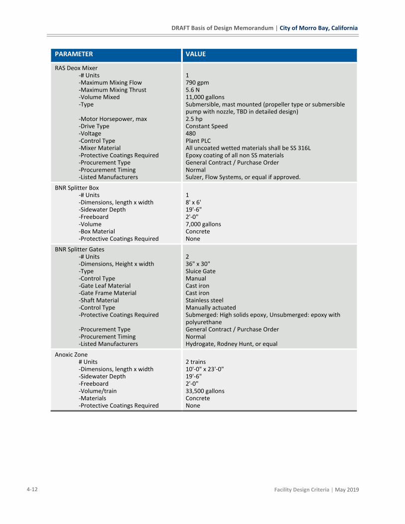
DRAFT Basis of Design Memorandum | City of Morro Bay, California
4-12 Facility Design Criteria | May 2019
PARAMETER VALUE
RAS Deox Mixer -# Units -Maximum Mixing Flow -Maximum Mixing Thrust -Volume Mixed -Type -Motor Horsepower, max -Drive Type -Voltage -Control Type -Mixer Material -Protective Coatings Required -Procurement Type -Procurement Timing -Listed Manufacturers
1 790 gpm 5.6 N 11,000 gallons Submersible, mast mounted (propeller type or submersible pump with nozzle, TBD in detailed design) 2.5 hp Constant Speed 480 Plant PLC All uncoated wetted materials shall be SS 316L Epoxy coating of all non SS materials General Contract / Purchase Order Normal Sulzer, Flow Systems, or equal if approved.
BNR Splitter Box -# Units -Dimensions, length x width -Sidewater Depth -Freeboard -Volume -Box Material -Protective Coatings Required
1 8' x 6' 19'-6" 2'-0" 7,000 gallons Concrete None
BNR Splitter Gates -# Units -Dimensions, Height x width -Type -Control Type -Gate Leaf Material -Gate Frame Material -Shaft Material -Control Type -Protective Coatings Required -Procurement Type -Procurement Timing -Listed Manufacturers
2 36" x 30" Sluice Gate Manual Cast iron Cast iron Stainless steel Manually actuated Submerged: High solids epoxy, Unsubmerged: epoxy with polyurethane General Contract / Purchase Order Normal Hydrogate, Rodney Hunt, or equal
Anoxic Zone # Units -Dimensions, length x width -Sidewater Depth -Freeboard -Volume/train -Materials -Protective Coatings Required
2 trains 10'-0" x 23'-0" 19'-6" 2'-0" 33,500 gallons Concrete None

City of Morro Bay, California | DRAFT Basis of Design Memorandum
| Facility Design Criteria 4-13
PARAMETER VALUE
Anoxic Mixer -# Units -Maximum Mixing Flow -Maximum Thrust -Volume -Type -Motor Horsepower, max -Drive Type -Voltage -Control Type -Mixer Material -Protective Coatings Required -Procurement Type -Procurement Timing -Listed Manufacturers
1 per train 5,500 gpm 50 N to 120 N 33,500 gallons per train Submersible mixer, mast mounted (propeller type or submersible pump with nozzle, TBD in detailed design) 2.5 hp Constant Speed 480 Plant PLC monitoring All uncoated wetted materials shall be SS 316L Epoxy coating of all non SS materials General Contract / Purchase Order Normal Sulzer, Flow Systems, or equal if approved.
Aerobic Basin -# Units -Dimensions, length x width -Sidewater Depth -Freeboard -Volume/train -Material -Protective Coatings Required
2 trains 58'-6" x 23'-0" 18' 3'-6" @ rated flow 180,000 gallons Concrete None
Fine Bubbled Diffused Aeration -# Units/ train -Total Units -Zone 1 Air Flow -Zone 1 Diffusers -Zone 2 Air Flow -Zone 2 Diffusers -Diffuser Type -Diffuser, Material -Piping and Accessories, Material -Protective Coatings Required -Procurement Type -Procurement Timing -Listed Manufacturers
2 aeration zones per train 4 aeration zones 675 scfm per train Minimum 170 diffusers per train 353 scfm per train Minimum 90 diffusers per train Fine bubble disc EPDM SS 316L (Drop Pipes and Cooling Loops) with PVC grids None General Contract / Purchase Order Normal Xylem, Environmental Dynamics, Sanitaire, or equal if approved.
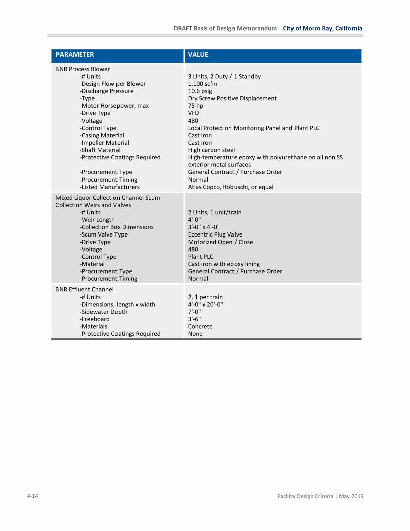
DRAFT Basis of Design Memorandum | City of Morro Bay, California
4-14 Facility Design Criteria | May 2019
PARAMETER VALUE
BNR Process Blower -# Units -Design Flow per Blower -Discharge Pressure -Type -Motor Horsepower, max -Drive Type -Voltage -Control Type -Casing Material -Impeller Material -Shaft Material -Protective Coatings Required -Procurement Type -Procurement Timing -Listed Manufacturers
3 Units, 2 Duty / 1 Standby 1,100 scfm 10.6 psig Dry Screw Positive Displacement 75 hp VFD 480 Local Protection Monitoring Panel and Plant PLC Cast iron Cast iron High carbon steel High-temperature epoxy with polyurethane on all non SS exterior metal surfaces General Contract / Purchase Order Normal Atlas Copco, Robuschi, or equal
Mixed Liquor Collection Channel Scum Collection Weirs and Valves
-# Units -Weir Length -Collection Box Dimensions -Scum Valve Type -Drive Type -Voltage -Control Type -Material -Procurement Type -Procurement Timing
2 Units, 1 unit/train 4'-0" 3'-0" x 4'-0" Eccentric Plug Valve Motorized Open / Close 480 Plant PLC Cast iron with epoxy lining General Contract / Purchase Order Normal
BNR Effluent Channel -# Units -Dimensions, length x width -Sidewater Depth -Freeboard -Materials -Protective Coatings Required
2, 1 per train 4'-0" x 20'-0" 7'-0" 3'-6" Concrete None

City of Morro Bay, California | DRAFT Basis of Design Memorandum
| Facility Design Criteria 4-15
PARAMETER VALUE
MBR Feed Pumps -# Units -Design Flow per Pump -Head -Type -Motor Horsepower -Drive Type -Voltage -Control Type -Stator and oil chamber housing -Propeller Shaft -Propeller & Mechanical Seal -Propeller -Inlet Cone -Guide Rail -Protective Coatings Required -Procurement Type -Procurement Timing -Listed Manufacturers
2 Units, 1 per train 0.6 to 4.85 mgd (5Q MBR train capacity) 3' to 4' Horizontal, submersible propeller pump 12.5 hp VFD 480 Plant PLC SS 316 Alloy steel, hard chrome plated; or SS 316. SS with tungsten carbide or silicon carbide rings. SS 316 SS 316 SS 316 Epoxy coating of non SS metals General Contract / Purchase Order Normal Sulzer, Flow Systems, or equal if approved.
BNR Effluent Isolation Valves -# Units -Type -Drive Type -Voltage -Control Type -Material -Procurement Type -Procurement Timing
2, 1 per train Knife Gate Motor operated open/close 480 Plant PLC Epoxy coated steel/iron or stainless steel components General Contract / Purchase Order Normal
BNR Tank Drain Pumps
Shared with MBR Tanks Drain Pump via manual valving and manually coupled hose.
WAS / Scum Tank -# Units -Dimensions, diameter -Sidewater Depth -Freeboard -Volume -Material -Protective Coatings Required
1 8'-0" 8'-0" 2'-0" 3,000 gallons FRP No lining, epoxy with polyurethane exterior coating

DRAFT Basis of Design Memorandum | City of Morro Bay, California
4-16 Facility Design Criteria | May 2019
PARAMETER VALUE
BNR WAS / Scum Pumps -# Units -Design Flow per Pump -Head -Type -Motor Horsepower -Drive Type -Voltage -Control Type -Barrel/ Case Material -Inner Case Material -Impeller Material -Shaft Material -Protective Coatings Required -Procurement Type -Procurement Timing -Listed Manufacturers
2 Units, 1 for WAS, 1 for Scum, Interchangeable 40 gpm 25' Rotary Lobe 4 hp VFD 480 Plant PLC Cast iron Corrosion resistant, material TBD Corrosion resistant or protected, material TBD Corrosion resistant or protected, material TBD Epoxy coating of non SS metals General Contract / Purchase Order Normal Borger, Netzsch, or equal if approved.
BNR WAS Pump and Combined WAS / Scum Flow Meters
-# Units -Design Flow Range per Unit -Type -Diameter -Voltage -Control Type -Protective Coatings Required -Procurement Type -Procurement Timing
2 0-60 gpm Magnetic 2" 120 Plant PLC Epoxy with polyurethane coating General Contract / Purchase Order Normal
4.2.2 Membrane Bioreactor (MBR) System
Mixed liquor effluent from each BNR train is pumped to a common MLSS header pipe. The MBR
feed pumps feed the MBR trains and drive RAS flow return to the front of the BNR train. The
membranes filter the inorganics and organics larger than the membrane pore size and provide a
degree of pathogen removal. MBR Filtrate is sent to the RO Feed Tank. The remaining flow exits
the MBR basins over the RAS weir. From the RAS weir channel, the water is set to the Deox Tank
and back to the head of the BNR process. WAS is wasted from the RAS pipe via flow control pump.
The MBR system components include membrane cassettes, filtrate pumps, coarse bubble diffuser
grids and dedicated blower, and a Clean-In-Place. To maintain performance, the MBR membranes
are cleaned through both physical and chemical means, including aeration, maintenance and
recovery cleans by an acid (citric acid) and/or base (sodium hypochlorite).
The MBR system equipment and configuration is vendor specific. The configuration shown herein
is typical, utilizing typical equipment and function. The design configuration will be updated when
a vendor is selected.
The design criteria for the MBR system are provided in Table 4-7.
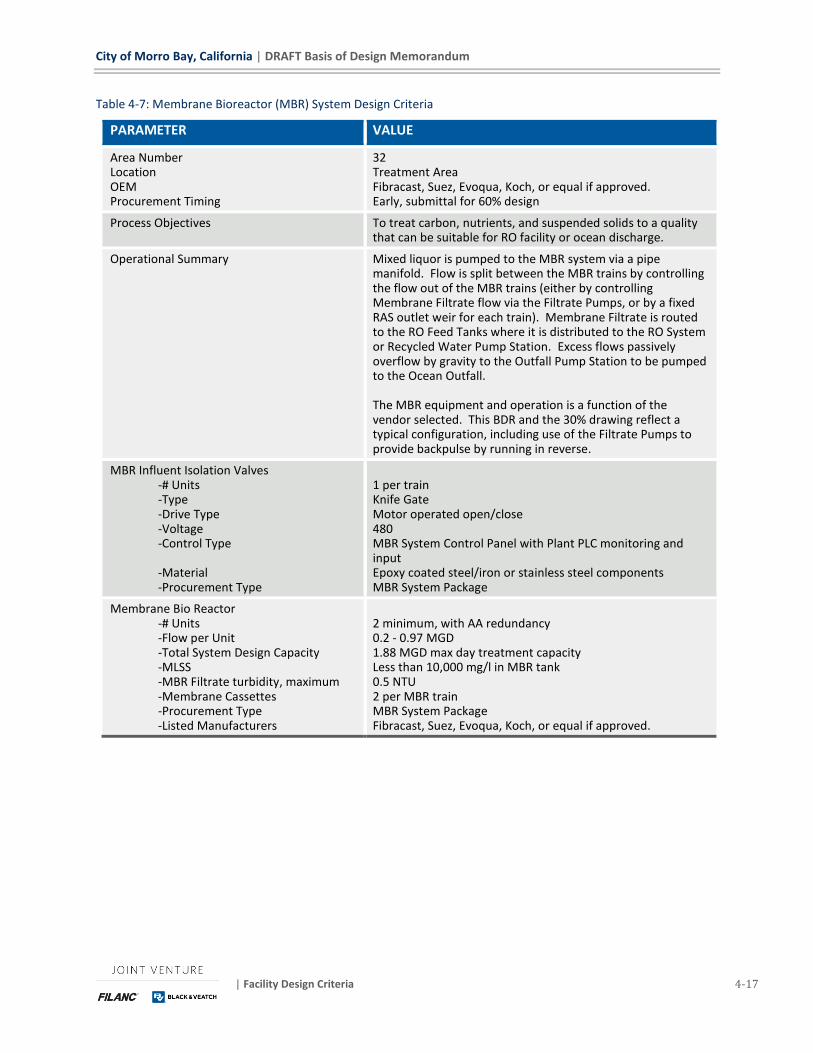
City of Morro Bay, California | DRAFT Basis of Design Memorandum
| Facility Design Criteria 4-17
Table 4-7: Membrane Bioreactor (MBR) System Design Criteria
PARAMETER VALUE
Area Number Location OEM Procurement Timing
32 Treatment Area Fibracast, Suez, Evoqua, Koch, or equal if approved. Early, submittal for 60% design
Process Objectives To treat carbon, nutrients, and suspended solids to a quality that can be suitable for RO facility or ocean discharge.
Operational Summary Mixed liquor is pumped to the MBR system via a pipe manifold. Flow is split between the MBR trains by controlling the flow out of the MBR trains (either by controlling Membrane Filtrate flow via the Filtrate Pumps, or by a fixed RAS outlet weir for each train). Membrane Filtrate is routed to the RO Feed Tanks where it is distributed to the RO System or Recycled Water Pump Station. Excess flows passively overflow by gravity to the Outfall Pump Station to be pumped to the Ocean Outfall. The MBR equipment and operation is a function of the vendor selected. This BDR and the 30% drawing reflect a typical configuration, including use of the Filtrate Pumps to provide backpulse by running in reverse.
MBR Influent Isolation Valves -# Units -Type -Drive Type -Voltage -Control Type -Material -Procurement Type
1 per train Knife Gate Motor operated open/close 480 MBR System Control Panel with Plant PLC monitoring and input Epoxy coated steel/iron or stainless steel components MBR System Package
Membrane Bio Reactor -# Units -Flow per Unit -Total System Design Capacity -MLSS -MBR Filtrate turbidity, maximum -Membrane Cassettes -Procurement Type -Listed Manufacturers
2 minimum, with AA redundancy 0.2 - 0.97 MGD 1.88 MGD max day treatment capacity Less than 10,000 mg/l in MBR tank 0.5 NTU 2 per MBR train MBR System Package Fibracast, Suez, Evoqua, Koch, or equal if approved.
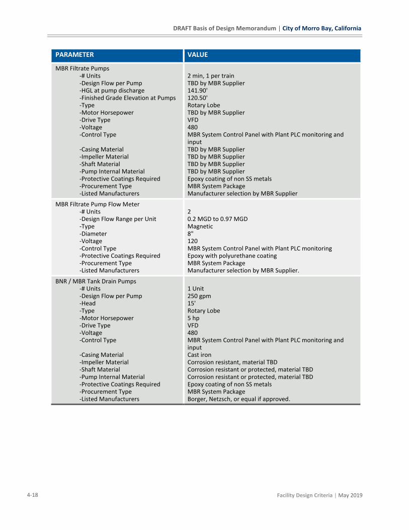
DRAFT Basis of Design Memorandum | City of Morro Bay, California
4-18 Facility Design Criteria | May 2019
PARAMETER VALUE
MBR Filtrate Pumps -# Units -Design Flow per Pump -HGL at pump discharge -Finished Grade Elevation at Pumps -Type -Motor Horsepower -Drive Type -Voltage -Control Type -Casing Material -Impeller Material -Shaft Material -Pump Internal Material -Protective Coatings Required -Procurement Type -Listed Manufacturers
2 min, 1 per train TBD by MBR Supplier 141.90' 120.50' Rotary Lobe TBD by MBR Supplier VFD 480 MBR System Control Panel with Plant PLC monitoring and input TBD by MBR Supplier TBD by MBR Supplier TBD by MBR Supplier TBD by MBR Supplier Epoxy coating of non SS metals MBR System Package Manufacturer selection by MBR Supplier
MBR Filtrate Pump Flow Meter -# Units -Design Flow Range per Unit -Type -Diameter -Voltage -Control Type -Protective Coatings Required -Procurement Type -Listed Manufacturers
2 0.2 MGD to 0.97 MGD Magnetic 8" 120 MBR System Control Panel with Plant PLC monitoring Epoxy with polyurethane coating MBR System Package Manufacturer selection by MBR Supplier.
BNR / MBR Tank Drain Pumps -# Units -Design Flow per Pump -Head -Type -Motor Horsepower -Drive Type -Voltage -Control Type -Casing Material -Impeller Material -Shaft Material -Pump Internal Material -Protective Coatings Required -Procurement Type -Listed Manufacturers
1 Unit 250 gpm 15' Rotary Lobe 5 hp VFD 480 MBR System Control Panel with Plant PLC monitoring and input Cast iron Corrosion resistant, material TBD Corrosion resistant or protected, material TBD Corrosion resistant or protected, material TBD Epoxy coating of non SS metals MBR System Package Borger, Netzsch, or equal if approved.
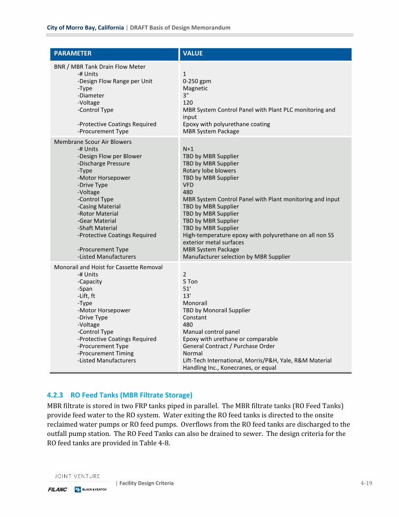
City of Morro Bay, California | DRAFT Basis of Design Memorandum
| Facility Design Criteria 4-19
PARAMETER VALUE
BNR / MBR Tank Drain Flow Meter -# Units -Design Flow Range per Unit -Type -Diameter -Voltage -Control Type -Protective Coatings Required -Procurement Type
1 0-250 gpm Magnetic 3" 120 MBR System Control Panel with Plant PLC monitoring and input Epoxy with polyurethane coating MBR System Package
Membrane Scour Air Blowers -# Units -Design Flow per Blower -Discharge Pressure -Type -Motor Horsepower -Drive Type -Voltage -Control Type -Casing Material -Rotor Material -Gear Material -Shaft Material -Protective Coatings Required -Procurement Type -Listed Manufacturers
N+1 TBD by MBR Supplier TBD by MBR Supplier Rotary lobe blowers TBD by MBR Supplier VFD 480 MBR System Control Panel with Plant monitoring and input TBD by MBR Supplier TBD by MBR Supplier TBD by MBR Supplier TBD by MBR Supplier High-temperature epoxy with polyurethane on all non SS exterior metal surfaces MBR System Package Manufacturer selection by MBR Supplier
Monorail and Hoist for Cassette Removal -# Units -Capacity -Span -Lift, ft -Type -Motor Horsepower -Drive Type -Voltage -Control Type -Protective Coatings Required -Procurement Type -Procurement Timing -Listed Manufacturers
2 5 Ton 51' 13' Monorail TBD by Monorail Supplier Constant 480 Manual control panel Epoxy with urethane or comparable General Contract / Purchase Order Normal Lift-Tech International, Morris/P&H, Yale, R&M Material Handling Inc., Konecranes, or equal
4.2.3 RO Feed Tanks (MBR Filtrate Storage)
MBR filtrate is stored in two FRP tanks piped in parallel. The MBR filtrate tanks (RO Feed Tanks)
provide feed water to the RO system. Water exiting the RO feed tanks is directed to the onsite
reclaimed water pumps or RO feed pumps. Overflows from the RO feed tanks are discharged to the
outfall pump station. The RO Feed Tanks can also be drained to sewer. The design criteria for the
RO feed tanks are provided in Table 4-8.
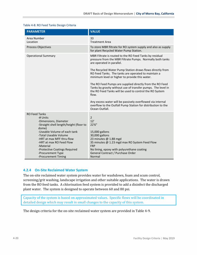
DRAFT Basis of Design Memorandum | City of Morro Bay, California
4-20 Facility Design Criteria | May 2019
Table 4-8: RO Feed Tanks Design Criteria
PARAMETER VALUE
Area Number Location
33 Treatment Area
Process Objectives To store MBR filtrate for RO system supply and also as supply for plant Recycled Water Pump Station.
Operational Summary MBR Filtrate is routed to the RO Feed Tanks by residual pressure from the MBR Filtrate Pumps. Normally both tanks are operated in parallel. The Recycled Water Pump Station draws flows directly from RO Feed Tanks. The tanks are operated to maintain a minimum level or higher to provide this water. The RO Feed Pumps are supplied directly from the RO Feed Tanks by gravity without use of transfer pumps. The level in the RO Feed Tanks will be used to control the RO System flow. Any excess water will be passively overflowed via internal overflow to the Outfall Pump Station for distribution to the Ocean Outfall.
RO Feed Tanks -# Units -Dimensions, Diameter -Straight shell length/height (floor to dome) -Useable Volume of each tank -Total Useable Volume -HRT at max MFF thru-flow -HRT at max RO Feed Flow -Material -Protective Coatings Required -Procurement Type -Procurement Timing
2 12' 22'6" 15,000 gallons 30,000 gallons 23 minutes @ 1.88 mgd 35 minutes @ 1.23 mgd max RO System Feed Flow FRP No lining, epoxy with polyurethane coating General Contract / Purchase Order Normal
4.2.4 On-Site Reclaimed Water System
The on-site reclaimed water system provides water for washdown, foam and scum control,
screening/grit washing, landscape irrigation and other suitable applications. The water is drawn
from the RO feed tanks. A chlorination feed system is provided to add a disinfect the discharged
plant water. The system is designed to operate between 60 and 80 psi.
Capacity of the system is based on approximated values. Specific flows will be coordinated in
detailed design which may result in small changes to the capacity of this system.
The design criteria for the on-site reclaimed water system are provided in Table 4-9.

City of Morro Bay, California | DRAFT Basis of Design Memorandum
| Facility Design Criteria 4-21
Table 4-9: On-Site Reclaimed Water System Design Criteria
PARAMETER VALUE
Area Number Location
34 Treatment Area
Process Objectives To provide water for washdown, foam and scum control, screening/grit washing, landscape irrigation and other suitable purposes.
Operational Summary Pumps are operated to maintain a set pressure range in the discharge piping.
Onsite Recycled Water Pumps -# Units -Design Flow per Pump -Head (minimum rated) -Type -Motor Horsepower, max -Drive Type -Voltage -Control Type -Pump Casing Material -Impeller Material -Shaft Material -Protective Coatings Required -Procurement Type -Procurement Timing -Listed Manufacturers
2 (1 duty/1standby for normal demand and 2 duty for peak demand)) 75 gpm each 175' TDH End suction centrifugal pumps 5 hp VFD 480 Plant PLC Epoxy-coated cast-iron or SS 316 SS SS Epoxy with polyurethane coating General Contract / Purchase Order Normal Fairbanks Morse/Pentair, Grunfos, Xylem or equal if approved
Onsite Recycled Water Pump Flow Meter -# Units -Design Flow Range per Unit -Type -Diameter -Voltage -Control Type -Protective Coatings Required -Procurement Type -Procurement Timing
1 0-200 gpm Magnetic 3" 120 Plant PLC Epoxy with polyurethane coating General Contract / Purchase Order Normal
Air Bladder Tank -# Units -Volume -Material -Protective Coatings Required
-Procurement Type -Procurement Timing -Listed Manufacturers
1 500 gallons Steel Vessel with EPDM or similar bladder
All wetted steel components are epoxy coated, epoxy with polyurethane coating or similar General Contract / Purchase Order Normal Amtrol WellXTroll, or similar
4.3 RO/UV BUILDING – AREA 50 The advanced treatment system to produce Indirect Potable Reuse (IPR) water is housed in the
RO/UV Building. The system includes a Reverse-Osmosis (RO) purification system and Ultraviolet
Advanced Oxidation Process (UVAOP) disinfection and trace compound oxidation process.
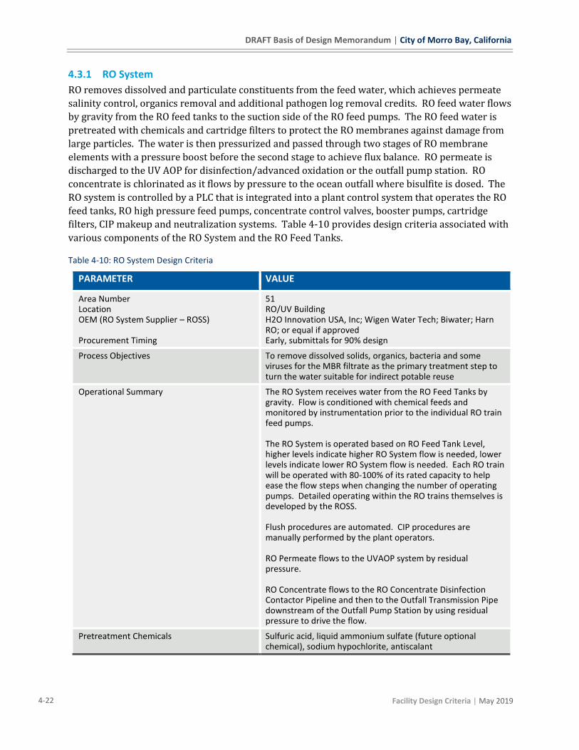
DRAFT Basis of Design Memorandum | City of Morro Bay, California
4-22 Facility Design Criteria | May 2019
4.3.1 RO System
RO removes dissolved and particulate constituents from the feed water, which achieves permeate
salinity control, organics removal and additional pathogen log removal credits. RO feed water flows
by gravity from the RO feed tanks to the suction side of the RO feed pumps. The RO feed water is
pretreated with chemicals and cartridge filters to protect the RO membranes against damage from
large particles. The water is then pressurized and passed through two stages of RO membrane
elements with a pressure boost before the second stage to achieve flux balance. RO permeate is
discharged to the UV AOP for disinfection/advanced oxidation or the outfall pump station. RO
concentrate is chlorinated as it flows by pressure to the ocean outfall where bisulfite is dosed. The
RO system is controlled by a PLC that is integrated into a plant control system that operates the RO
feed tanks, RO high pressure feed pumps, concentrate control valves, booster pumps, cartridge
filters, CIP makeup and neutralization systems. Table 4-10 provides design criteria associated with
various components of the RO System and the RO Feed Tanks.
Table 4-10: RO System Design Criteria
PARAMETER VALUE
Area Number Location OEM (RO System Supplier – ROSS) Procurement Timing
51 RO/UV Building H2O Innovation USA, Inc; Wigen Water Tech; Biwater; Harn RO; or equal if approved Early, submittals for 90% design
Process Objectives To remove dissolved solids, organics, bacteria and some viruses for the MBR filtrate as the primary treatment step to turn the water suitable for indirect potable reuse
Operational Summary The RO System receives water from the RO Feed Tanks by gravity. Flow is conditioned with chemical feeds and monitored by instrumentation prior to the individual RO train feed pumps. The RO System is operated based on RO Feed Tank Level, higher levels indicate higher RO System flow is needed, lower levels indicate lower RO System flow is needed. Each RO train will be operated with 80-100% of its rated capacity to help ease the flow steps when changing the number of operating pumps. Detailed operating within the RO trains themselves is developed by the ROSS. Flush procedures are automated. CIP procedures are manually performed by the plant operators. RO Permeate flows to the UVAOP system by residual pressure. RO Concentrate flows to the RO Concentrate Disinfection Contactor Pipeline and then to the Outfall Transmission Pipe downstream of the Outfall Pump Station by using residual pressure to drive the flow.
Pretreatment Chemicals Sulfuric acid, liquid ammonium sulfate (future optional chemical), sodium hypochlorite, antiscalant
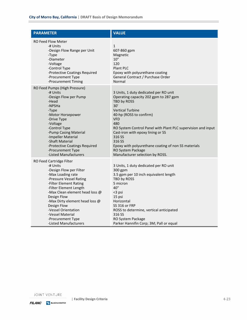
City of Morro Bay, California | DRAFT Basis of Design Memorandum
| Facility Design Criteria 4-23
PARAMETER VALUE
RO Feed Flow Meter -# Units -Design Flow Range per Unit -Type -Diameter -Voltage -Control Type -Protective Coatings Required -Procurement Type -Procurement Timing
1 607-860 gpm Magnetic 10" 120 Plant PLC Epoxy with polyurethane coating General Contract / Purchase Order Normal
RO Feed Pumps (High Pressure) -# Units -Design Flow per Pump -Head -NPSHa -Type -Motor Horsepower -Drive Type -Voltage -Control Type -Pump Casing Material -Impeller Material -Shaft Material -Protective Coatings Required -Procurement Type -Listed Manufacturers
3 Units, 1 duty dedicated per RO unit Operating capacity 202 gpm to 287 gpm TBD by ROSS 30' Vertical Turbine 40-hp (ROSS to confirm) VFD 480 RO System Control Panel with Plant PLC supervision and input Cast-iron with epoxy lining or SS 316 SS 316 SS Epoxy with polyurethane coating of non SS materials RO System Package Manufacturer selection by ROSS.
RO Feed Cartridge Filter -# Units -Design Flow per Filter -Max Loading rate -Pressure Vessel Rating -Filter Element Rating -Filter Element Length -Max Clean element head loss @ Design Flow -Max Dirty element head loss @ Design Flow -Vessel Orientation -Vessel Material -Procurement Type -Listed Manufacturers
3 Units, 1 duty dedicated per RO unit 300 gpm 3.5 gpm per 10 inch equivalent length TBD by ROSS 5 micron 40" <3 psi 15 psi Horizontal SS 316 or FRP ROSS to determine, vertical anticipated 316 SS RO System Package Parker Hannifin Corp; 3M; Pall or equal
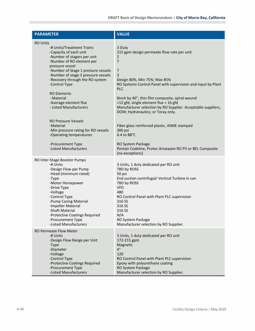
DRAFT Basis of Design Memorandum | City of Morro Bay, California
4-24 Facility Design Criteria | May 2019
PARAMETER VALUE
RO Units -# Units/Treatment Trains -Capacity of each unit -Number of stagers per unit -Number of RO element per pressure vessel -Number of Stage 1 pressure vessels -Number of stage 2 pressure vessels -Recovery through the RO system -Control Type RO Elements - Material -Average element flux - Listed Manufacturers RO Pressure Vessels -Material -Min pressure rating for RO vessels -Operating temperatures -Procurement Type -Listed Manufacturers
3 Duty 215 gpm design permeate flow rate per unit 2 7 7 3 Design 80%, Min 75%; Max 85% RO Systems Control Panel with supervision and input by Plant PLC. 8inch by 40", thin film composite, spiral wound <12 gfd, single element flux < 16 gfd Manufacturer selection by RO Supplier. Acceptable suppliers, DOW; Hydranautics; or Toray only. Fiber glass reinforced plastic, ASME stamped 300 psi 4.4 to 88°C RO System Package Pentair Codeline, Protec Arisawam RO PV or BEL Composite (no exceptions)
RO Inter-Stage Booster Pumps -# Units -Design Flow per Pump -Head (minimum rated) -Type -Motor Horsepower -Drive Type -Voltage -Control Type -Pump Casing Material -Impeller Material -Shaft Material -Protective Coatings Required -Procurement Type -Listed Manufacturers
3 Units, 1 duty dedicated per RO unit TBD by ROSS 50 psi End suction centrifugal/ Vertical Turbine in can TBD by ROSS VFD 480 RO Control Panel with Plant PLC supervision 316 SS 316 SS 316 SS N/A RO System Package Manufacturer selection by RO Supplier.
RO Permeate Flow Meter -# Units -Design Flow Range per Unit -Type -Diameter -Voltage -Control Type -Protective Coatings Required -Procurement Type -Listed Manufacturers
3 Units, 1 duty dedicated per RO unit 172-215 gpm Magnetic 4" 120 RO Control Panel with Plant PLC supervision Epoxy with polyurethane coating RO System Package Manufacturer selection by RO Supplier.
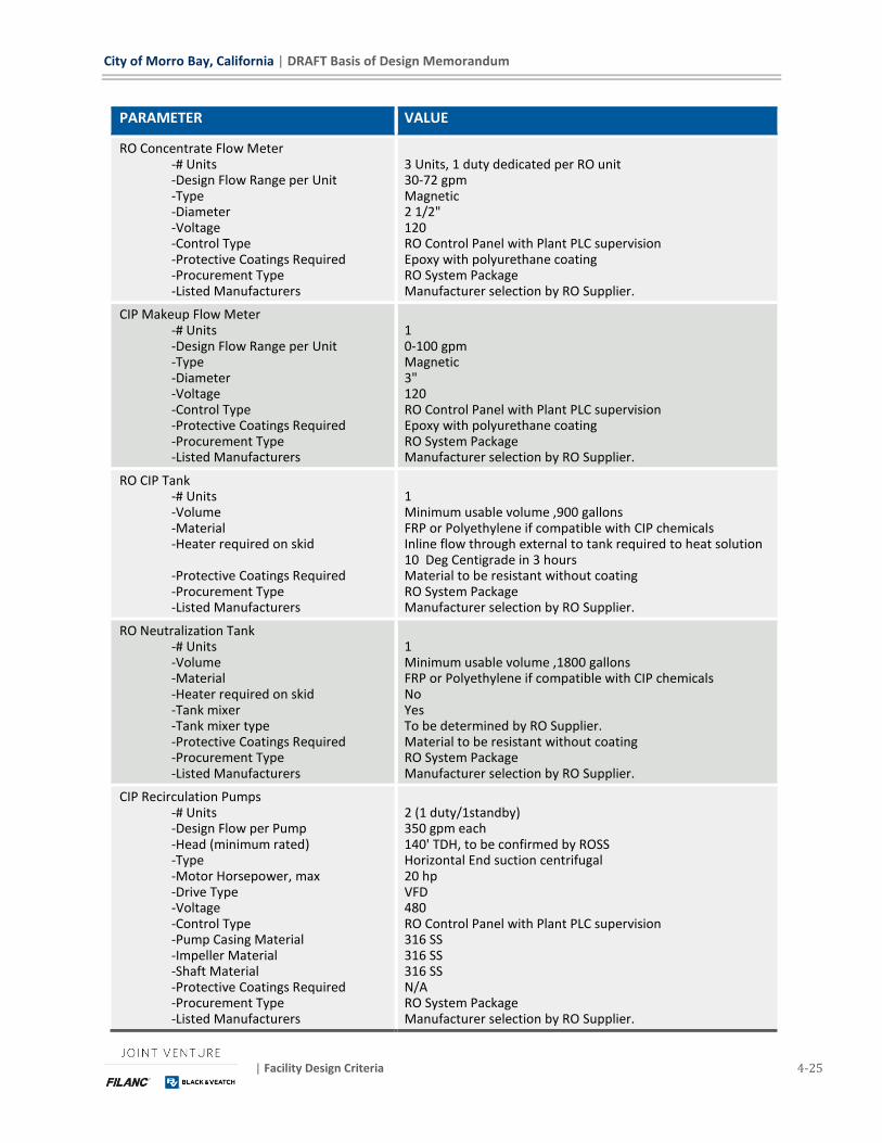
City of Morro Bay, California | DRAFT Basis of Design Memorandum
| Facility Design Criteria 4-25
PARAMETER VALUE
RO Concentrate Flow Meter -# Units -Design Flow Range per Unit -Type -Diameter -Voltage -Control Type -Protective Coatings Required -Procurement Type -Listed Manufacturers
3 Units, 1 duty dedicated per RO unit 30-72 gpm Magnetic 2 1/2" 120 RO Control Panel with Plant PLC supervision Epoxy with polyurethane coating RO System Package Manufacturer selection by RO Supplier.
CIP Makeup Flow Meter -# Units -Design Flow Range per Unit -Type -Diameter -Voltage -Control Type -Protective Coatings Required -Procurement Type -Listed Manufacturers
1 0-100 gpm Magnetic 3" 120 RO Control Panel with Plant PLC supervision Epoxy with polyurethane coating RO System Package Manufacturer selection by RO Supplier.
RO CIP Tank -# Units -Volume -Material -Heater required on skid -Protective Coatings Required -Procurement Type -Listed Manufacturers
1 Minimum usable volume ,900 gallons FRP or Polyethylene if compatible with CIP chemicals Inline flow through external to tank required to heat solution 10 Deg Centigrade in 3 hours Material to be resistant without coating RO System Package Manufacturer selection by RO Supplier.
RO Neutralization Tank -# Units -Volume -Material -Heater required on skid -Tank mixer -Tank mixer type -Protective Coatings Required -Procurement Type -Listed Manufacturers
1 Minimum usable volume ,1800 gallons FRP or Polyethylene if compatible with CIP chemicals No Yes To be determined by RO Supplier. Material to be resistant without coating RO System Package Manufacturer selection by RO Supplier.
CIP Recirculation Pumps -# Units -Design Flow per Pump -Head (minimum rated) -Type -Motor Horsepower, max -Drive Type -Voltage -Control Type -Pump Casing Material -Impeller Material -Shaft Material -Protective Coatings Required -Procurement Type -Listed Manufacturers
2 (1 duty/1standby) 350 gpm each 140' TDH, to be confirmed by ROSS Horizontal End suction centrifugal 20 hp VFD 480 RO Control Panel with Plant PLC supervision 316 SS 316 SS 316 SS N/A RO System Package Manufacturer selection by RO Supplier.

DRAFT Basis of Design Memorandum | City of Morro Bay, California
4-26 Facility Design Criteria | May 2019
PARAMETER VALUE
RO CIP Cartridge Filter -# Units -Design Flow per Filter -Max Loading rate -Pressure Vessel Rating -Filter Element Rating -Filter Element Length -Max Clean element head loss @ Design Flow -Max Dirty element head loss @ Design Flow -Vessel Orientation -Vessel Material -Procurement Type -Listed Manufacturers
1 300 gpm <5 gpm per 10 inch equivalent length 100 psi TBD 5 micron 40" <3 psi 15 psi Horizontal/ Vertical 316 SS Vertical 316 SS Ro System Package Parker Hannifin Corp; 3M; Pall or equal
RO CIP Flow Meter -# Units -Design Flow Range per Unit -Type -Diameter -Voltage -Control Type -Protective Coatings Required -Procurement Type -Listed Manufacturers
1 280 to 420 gpm Magnetic 6" 120 Plant PLC Epoxy with polyurethane coating RO System Package Manufacturer selection by RO Supplier.
RO Flush Tank -# Units -Volume -Material -Heater required on skid -Protective Coatings Required -Procurement Type -Listed Manufacturers
1 Minimum usable volume ,2300 gallons FRP or Polyethylene No N/A RO System Package Manufacturer selection by RO Supplier.
RO Flush Pumps -# Units -Design Flow per Pump -Head (minimum rated) -Type -Motor Horsepower, max -Drive Type -Voltage -Control Type -Pump Casing Material -Impeller Material -Shaft Material -Protective Coatings Required -Procurement Type -Listed Manufacturers
2 (1 duty/1standby) 210 gpm each 140' TDH Horizontal end-suction centrifugal 15 max VFD 480 RO Control Panel with Plant PLC supervision 316 SS 316 SS 316 SS N/A RO System Package Manufacturer selection by RO Supplier.
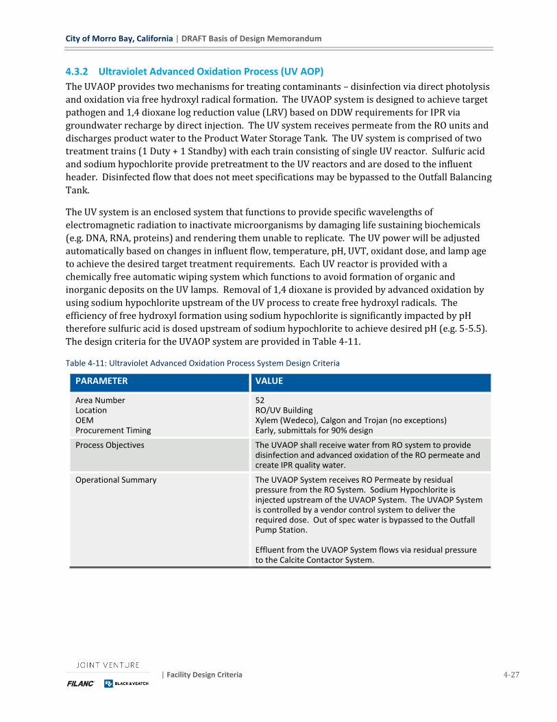
City of Morro Bay, California | DRAFT Basis of Design Memorandum
| Facility Design Criteria 4-27
4.3.2 Ultraviolet Advanced Oxidation Process (UV AOP)
The UVAOP provides two mechanisms for treating contaminants – disinfection via direct photolysis
and oxidation via free hydroxyl radical formation. The UVAOP system is designed to achieve target
pathogen and 1,4 dioxane log reduction value (LRV) based on DDW requirements for IPR via
groundwater recharge by direct injection. The UV system receives permeate from the RO units and
discharges product water to the Product Water Storage Tank. The UV system is comprised of two
treatment trains (1 Duty + 1 Standby) with each train consisting of single UV reactor. Sulfuric acid
and sodium hypochlorite provide pretreatment to the UV reactors and are dosed to the influent
header. Disinfected flow that does not meet specifications may be bypassed to the Outfall Balancing
Tank.
The UV system is an enclosed system that functions to provide specific wavelengths of
electromagnetic radiation to inactivate microorganisms by damaging life sustaining biochemicals
(e.g. DNA, RNA, proteins) and rendering them unable to replicate. The UV power will be adjusted
automatically based on changes in influent flow, temperature, pH, UVT, oxidant dose, and lamp age
to achieve the desired target treatment requirements. Each UV reactor is provided with a
chemically free automatic wiping system which functions to avoid formation of organic and
inorganic deposits on the UV lamps. Removal of 1,4 dioxane is provided by advanced oxidation by
using sodium hypochlorite upstream of the UV process to create free hydroxyl radicals. The
efficiency of free hydroxyl formation using sodium hypochlorite is significantly impacted by pH
therefore sulfuric acid is dosed upstream of sodium hypochlorite to achieve desired pH (e.g. 5-5.5).
The design criteria for the UVAOP system are provided in Table 4-11.
Table 4-11: Ultraviolet Advanced Oxidation Process System Design Criteria
PARAMETER VALUE
Area Number Location OEM Procurement Timing
52 RO/UV Building Xylem (Wedeco), Calgon and Trojan (no exceptions) Early, submittals for 90% design
Process Objectives The UVAOP shall receive water from RO system to provide disinfection and advanced oxidation of the RO permeate and create IPR quality water.
Operational Summary The UVAOP System receives RO Permeate by residual pressure from the RO System. Sodium Hypochlorite is injected upstream of the UVAOP System. The UVAOP System is controlled by a vendor control system to deliver the required dose. Out of spec water is bypassed to the Outfall Pump Station. Effluent from the UVAOP System flows via residual pressure to the Calcite Contactor System.
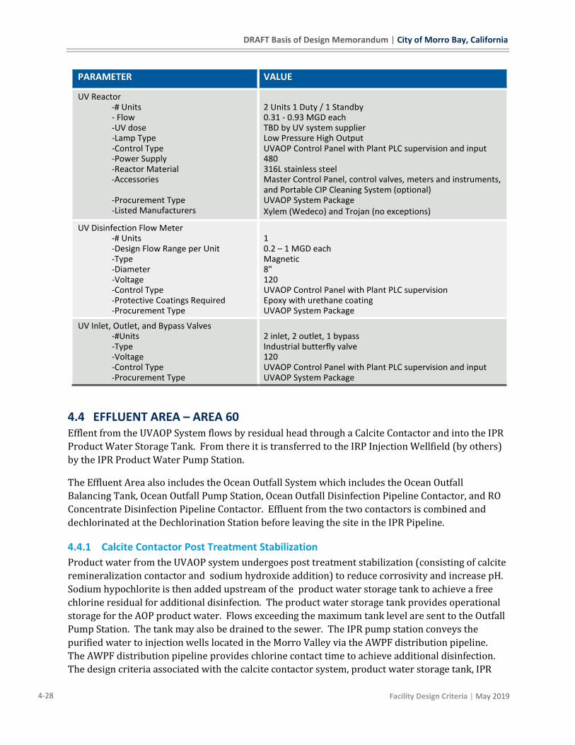
DRAFT Basis of Design Memorandum | City of Morro Bay, California
4-28 Facility Design Criteria | May 2019
PARAMETER VALUE
UV Reactor -# Units - Flow -UV dose -Lamp Type -Control Type -Power Supply -Reactor Material -Accessories
-Procurement Type -Listed Manufacturers
2 Units 1 Duty / 1 Standby 0.31 - 0.93 MGD each TBD by UV system supplier Low Pressure High Output UVAOP Control Panel with Plant PLC supervision and input 480 316L stainless steel Master Control Panel, control valves, meters and instruments, and Portable CIP Cleaning System (optional) UVAOP System Package Xylem (Wedeco) and Trojan (no exceptions)
UV Disinfection Flow Meter -# Units -Design Flow Range per Unit -Type -Diameter -Voltage -Control Type -Protective Coatings Required -Procurement Type
1 0.2 – 1 MGD each Magnetic 8" 120 UVAOP Control Panel with Plant PLC supervision Epoxy with urethane coating UVAOP System Package
UV Inlet, Outlet, and Bypass Valves -#Units -Type -Voltage -Control Type -Procurement Type
2 inlet, 2 outlet, 1 bypass Industrial butterfly valve 120 UVAOP Control Panel with Plant PLC supervision and input UVAOP System Package
4.4 EFFLUENT AREA – AREA 60 Efflent from the UVAOP System flows by residual head through a Calcite Contactor and into the IPR
Product Water Storage Tank. From there it is transferred to the IRP Injection Wellfield (by others)
by the IPR Product Water Pump Station.
The Effluent Area also includes the Ocean Outfall System which includes the Ocean Outfall
Balancing Tank, Ocean Outfall Pump Station, Ocean Outfall Disinfection Pipeline Contactor, and RO
Concentrate Disinfection Pipeline Contactor. Effluent from the two contactors is combined and
dechlorinated at the Dechlorination Station before leaving the site in the IPR Pipeline.
4.4.1 Calcite Contactor Post Treatment Stabilization
Product water from the UVAOP system undergoes post treatment stabilization (consisting of calcite
remineralization contactor and sodium hydroxide addition) to reduce corrosivity and increase pH.
Sodium hypochlorite is then added upstream of the product water storage tank to achieve a free
chlorine residual for additional disinfection. The product water storage tank provides operational
storage for the AOP product water. Flows exceeding the maximum tank level are sent to the Outfall
Pump Station. The tank may also be drained to the sewer. The IPR pump station conveys the
purified water to injection wells located in the Morro Valley via the AWPF distribution pipeline.
The AWPF distribution pipeline provides chlorine contact time to achieve additional disinfection.
The design criteria associated with the calcite contactor system, product water storage tank, IPR

City of Morro Bay, California | DRAFT Basis of Design Memorandum
| Facility Design Criteria 4-29
pump station and the AWPF distribution pipeline disinfection system is provided in Table 4-12,
Table 4-13, Table 4-14, and Table 4-15 respectively.
Table 4-12: Calcite Contactor System Design Criteria
PARAMETER VALUE
Area Number Location OEM Procurement Timing
61 Effluent Area Wigen Water Technologies, Tonka Water, or equal if approved Early, submittals for 90% design
Process Objectives The purpose of the calcite contactor is to reduce the corrosivity and increase the pH of the UV AOP effluent.
Operational Summary The Calcite Contactor System receives Flow to the UVAOP System via residual pressure. The flow moves through calcite media to absorb minerals and then flows via residual pressure to the IPR Product Water Storage Tank. The Calcite Contractor is a passive system not requiring any online process control. Loading of new media and backwashing that media is manually performed by the operators. The Calcite Contractor is equipped with backwash pumps and Backwash Waste Holding Tank to allow for slow discharge of backwash waste to the plant sewer system to not cause a process upset.
Calcite Contactor Vessels -# Units -Design Flow -Design Working Pressure -Source Water -Influent Water Quality -Finished Water Quality Required
-Filter Media -Filter Media Quantity -Material -Protective Coatings Required -Procurement Type -Listed Manufacturers
2 (2 duty) One vessel sized to allow entire flow to pass through a single vessel so that the other can be taken offline for service or media loading. 0.93 mgd 100 psi or greater RO / UVAOP Effluent pH 5.12-5.46; Total Alkalinity 1.7-1.9 mg/ as CaC03; Calcium = 1.4 mg/L; Water Temp. 14-22 Deg C. pH 7-8.5; LSI > 0; Alkalinity 40-60 mg/L as CaC03; TDS 50-60 mg/L; turbidity < 1 NTU. Pur-cal or equal: 36" total depth above supporting gravel. The media shall have a uniformity coefficient less than 1.5. Adequate for 60 days operated 24 hours/day at maximum flow and average chemical demand Carbon steel Epoxy interior coating, epoxy with polyurethane exterior coating Calcite Contactor System Package To be determined to OEM
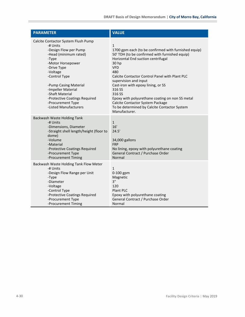
DRAFT Basis of Design Memorandum | City of Morro Bay, California
4-30 Facility Design Criteria | May 2019
PARAMETER VALUE
Calcite Contactor System Flush Pump -# Units -Design Flow per Pump -Head (minimum rated) -Type -Motor Horsepower -Drive Type -Voltage -Control Type -Pump Casing Material -Impeller Material -Shaft Material -Protective Coatings Required -Procurement Type -Listed Manufacturers
1 1700 gpm each (to be confirmed with furnished equip) 50' TDH (to be confirmed with furnished equip) Horizontal End suction centrifugal 30 hp VFD 480 Calcite Contactor Control Panel with Plant PLC supervision and input Cast-iron with epoxy lining, or SS 316 SS 316 SS Epoxy with polyurethane coating on non SS metal Calcite Contactor System Package To be determined by Calcite Contactor System Manufacturer.
Backwash Waste Holding Tank -# Units -Dimensions, Diameter -Straight shell length/height (floor to dome) -Volume -Material -Protective Coatings Required -Procurement Type -Procurement Timing
1 16' 24.5' 34,000 gallons FRP No lining, epoxy with polyurethane coating General Contract / Purchase Order Normal
Backwash Waste Holding Tank Flow Meter -# Units -Design Flow Range per Unit -Type -Diameter -Voltage -Control Type -Protective Coatings Required -Procurement Type -Procurement Timing
1 0-100 gpm Magnetic 3" 120 Plant PLC Epoxy with polyurethane coating General Contract / Purchase Order Normal
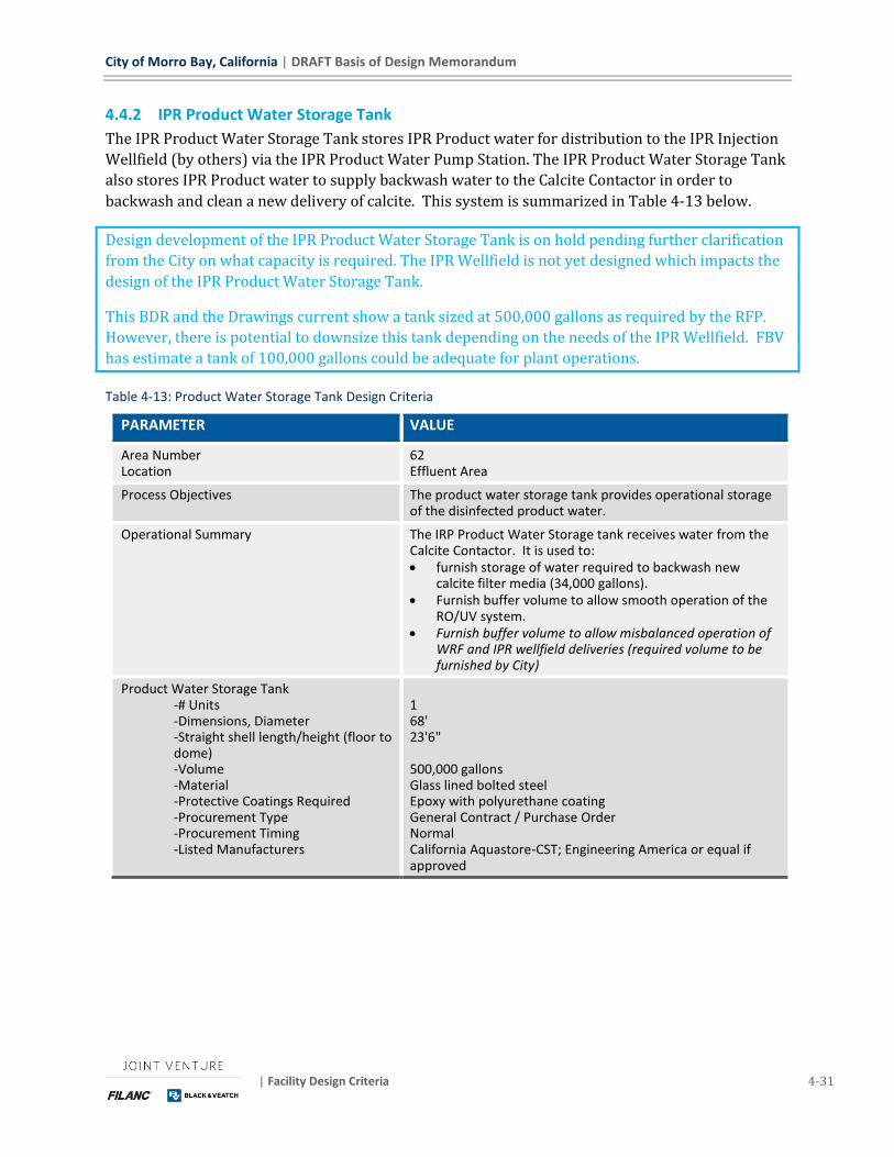
City of Morro Bay, California | DRAFT Basis of Design Memorandum
| Facility Design Criteria 4-31
4.4.2 IPR Product Water Storage Tank
The IPR Product Water Storage Tank stores IPR Product water for distribution to the IPR Injection
Wellfield (by others) via the IPR Product Water Pump Station. The IPR Product Water Storage Tank
also stores IPR Product water to supply backwash water to the Calcite Contactor in order to
backwash and clean a new delivery of calcite. This system is summarized in Table 4-13 below.
Design development of the IPR Product Water Storage Tank is on hold pending further clarification
from the City on what capacity is required. The IPR Wellfield is not yet designed which impacts the
design of the IPR Product Water Storage Tank.
This BDR and the Drawings current show a tank sized at 500,000 gallons as required by the RFP.
However, there is potential to downsize this tank depending on the needs of the IPR Wellfield. FBV
has estimate a tank of 100,000 gallons could be adequate for plant operations.
Table 4-13: Product Water Storage Tank Design Criteria
PARAMETER VALUE
Area Number Location
62 Effluent Area
Process Objectives The product water storage tank provides operational storage of the disinfected product water.
Operational Summary The IRP Product Water Storage tank receives water from the Calcite Contactor. It is used to: • furnish storage of water required to backwash new
calcite filter media (34,000 gallons). • Furnish buffer volume to allow smooth operation of the
RO/UV system. • Furnish buffer volume to allow misbalanced operation of
WRF and IPR wellfield deliveries (required volume to be furnished by City)
Product Water Storage Tank -# Units -Dimensions, Diameter -Straight shell length/height (floor to dome) -Volume -Material -Protective Coatings Required -Procurement Type -Procurement Timing -Listed Manufacturers
1 68' 23'6" 500,000 gallons Glass lined bolted steel Epoxy with polyurethane coating General Contract / Purchase Order Normal California Aquastore-CST; Engineering America or equal if approved

DRAFT Basis of Design Memorandum | City of Morro Bay, California
4-32 Facility Design Criteria | May 2019
4.4.3 IPR Product Water Pump Station
The IPR Product Water Pump Station pumps IPR Product Water via the IPR Product Water
Transmission Main (by others) to the IPR Wellfield for injection (by others). This facility is
summarized in Table 4-14 below.
Design development of the IPR Product Water Pump Station is on hold pending further clarification
from the City on what is required. The design of the IPR pipe (by others) is not complete, which
impacts the hydraulic design of this pump station. Furthermore, the design of the IPR pipe includes
surge mitigation which may require impacts to the design of the IPR Product Water Pump Station.
The design of the IPR Injection Wellfield (by others) is not complete, which impacts the hydraulic
design and operation of this pump station.
This BDR and the Drawings currently show the IPR Product Water Pump Station that was estimated
based on the limited RFP information.
Table 4-14: IPR Pump System Design Criteria
PARAMETER VALUE
Area Number Location
63 Effluent Area
Process Objectives The IPR pump station conveys the recycled water to injection wells located in the Morro Valley.
Operational Summary Operation of the IPR Product Water Pump Station is unknown until requirements are furnished by the City relative to the design of the IPR Transmission Main and IPR Injection Wellfield.
IPR Pumps -# Units -Design Flow per Pump -Head (minimum rated) -Type -Motor Horsepower, estimated max -Drive Type -Voltage -Control Type -Pump Casing Material -Impeller Material -Shaft Material -Protective Coatings Required -Procurement Type -Procurement Timing -Listed Manufacturers
3 (2 duty/1standby) 323 gpm each 63' TDH (166' discharge HGL) End suction centrifugal pumps 7.5 hp VFD 480 Plant PLC Epoxy-coated cast-iron or SS 316 SS 316 SS or similar Epoxy with polyurethane for non SS metal General Contract / Purchase Order Normal Fairbanks Morse/Pentair, Grunfos, Xylem or equal if approved
The IPR Product Water Transmission Main (by others) is also used as a supplemental disinfection
contactor. This facility is summarized in Table 4-15 below.
Design and operation of the IPR Product Water Transmission Main (by others) needs to be
coordinated to furnish the disinfection contact requirements stated below. If these values cannot
be met additional contact facilities may be required to achieve the needed log removal credits.

City of Morro Bay, California | DRAFT Basis of Design Memorandum
| Facility Design Criteria 4-33
Table 4-15: AWPF Distribution Pipeline Disinfection Design System Criteria
PARAMETER VALUE
Area Number
Location
Offsite
Offsite
Process Objectives Achieve additional disinfection of AWPF product water via
chlorine contact in the distribution pipeline.
Operational Summary The Transmission Main is used to also provide disinfection
contact time. This function is passively maintained by the
highpoint at Quintanna without requiring operational input.
CT Required for 4 log virus inactivation @ 14
Degrees C, pH 6-9
4.4 mg/L-min (EPA Guidance Manual Disinfection Profile and
Benchmarking August 1999)
Maximum pipeline flow rate 0.93 MGD
Pipeline Diameter 8"
Approx. Pipe Length to groundwater injection 9,504 ft
Approx. Pipe Length 100% full flow 4,752 ft (to high point of Quintana Road)
Pipe Volume 100% full flow 12,410 gallons
Contact time @ maximum flow associated
with full pipe segment
19.22 minutes
Pipeline Baffling Factor 1
Required Free Chlorine Residual at end of full
pipe segment
0.3 mg/L
CT Calculated at Max Flow - pipe full 5.7 mg/L-min
4.4.4 Outfall Pump Station
The Outfall Pump Station pumps flows to the Ocean Outfall (by others) via the Ocean Outfall
Transmission Main (by others). The Outfall Balancing Tank receives, blends, and equalizes flows
for the Outfall Pump Station. This system receives:
◼ Membrane Filtrate (MFF) from the MBR system
◼ Filtered Outfall Water (FOW) from the SAFE System
◼ RO Feed (ROF) and RO train permeate (ROP) bypass from the RO System
◼ UV Effluent (UVE) bypass from the UVAOP System
◼ Overflow (OF) from the IPR Product Water Storage Tank
This system is summarized in Table 4-16 below.
This system does not receive concentrate from the RO System. The residual pressure from that
system is used to route that flow to the Ocean Outfall Transmission Main downstream of the Outfall
Pump Station.
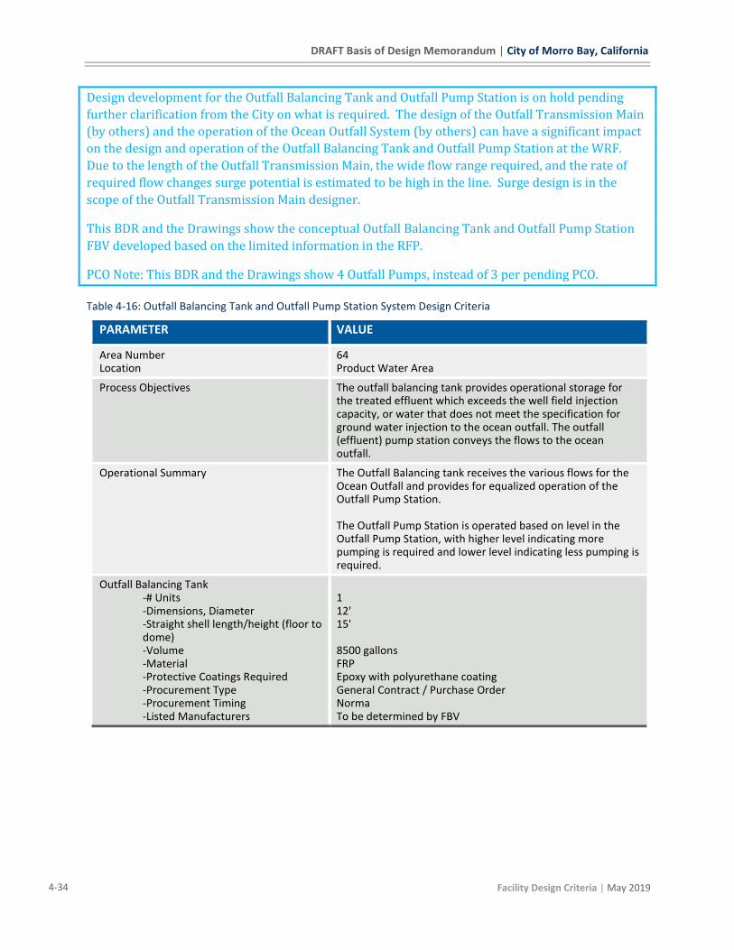
DRAFT Basis of Design Memorandum | City of Morro Bay, California
4-34 Facility Design Criteria | May 2019
Design development for the Outfall Balancing Tank and Outfall Pump Station is on hold pending
further clarification from the City on what is required. The design of the Outfall Transmission Main
(by others) and the operation of the Ocean Outfall System (by others) can have a significant impact
on the design and operation of the Outfall Balancing Tank and Outfall Pump Station at the WRF.
Due to the length of the Outfall Transmission Main, the wide flow range required, and the rate of
required flow changes surge potential is estimated to be high in the line. Surge design is in the
scope of the Outfall Transmission Main designer.
This BDR and the Drawings show the conceptual Outfall Balancing Tank and Outfall Pump Station
FBV developed based on the limited information in the RFP.
PCO Note: This BDR and the Drawings show 4 Outfall Pumps, instead of 3 per pending PCO.
Table 4-16: Outfall Balancing Tank and Outfall Pump Station System Design Criteria
PARAMETER VALUE
Area Number Location
64 Product Water Area
Process Objectives The outfall balancing tank provides operational storage for the treated effluent which exceeds the well field injection capacity, or water that does not meet the specification for ground water injection to the ocean outfall. The outfall (effluent) pump station conveys the flows to the ocean outfall.
Operational Summary The Outfall Balancing tank receives the various flows for the Ocean Outfall and provides for equalized operation of the Outfall Pump Station. The Outfall Pump Station is operated based on level in the Outfall Pump Station, with higher level indicating more pumping is required and lower level indicating less pumping is required.
Outfall Balancing Tank -# Units -Dimensions, Diameter -Straight shell length/height (floor to dome) -Volume -Material -Protective Coatings Required -Procurement Type -Procurement Timing -Listed Manufacturers
1 12' 15' 8500 gallons FRP Epoxy with polyurethane coating General Contract / Purchase Order Norma To be determined by FBV
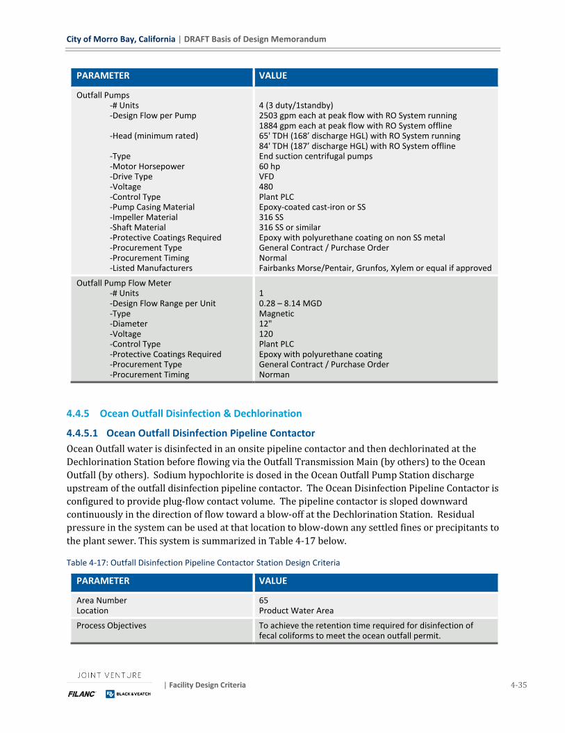
City of Morro Bay, California | DRAFT Basis of Design Memorandum
| Facility Design Criteria 4-35
PARAMETER VALUE
Outfall Pumps -# Units -Design Flow per Pump -Head (minimum rated) -Type -Motor Horsepower -Drive Type -Voltage -Control Type -Pump Casing Material -Impeller Material -Shaft Material -Protective Coatings Required -Procurement Type -Procurement Timing -Listed Manufacturers
4 (3 duty/1standby) 2503 gpm each at peak flow with RO System running 1884 gpm each at peak flow with RO System offline 65' TDH (168’ discharge HGL) with RO System running 84' TDH (187’ discharge HGL) with RO System offline End suction centrifugal pumps 60 hp VFD 480 Plant PLC Epoxy-coated cast-iron or SS 316 SS 316 SS or similar Epoxy with polyurethane coating on non SS metal General Contract / Purchase Order Normal Fairbanks Morse/Pentair, Grunfos, Xylem or equal if approved
Outfall Pump Flow Meter -# Units -Design Flow Range per Unit -Type -Diameter -Voltage -Control Type -Protective Coatings Required -Procurement Type -Procurement Timing
1 0.28 – 8.14 MGD Magnetic 12" 120 Plant PLC Epoxy with polyurethane coating General Contract / Purchase Order Norman
4.4.5 Ocean Outfall Disinfection & Dechlorination
4.4.5.1 Ocean Outfall Disinfection Pipeline Contactor
Ocean Outfall water is disinfected in an onsite pipeline contactor and then dechlorinated at the
Dechlorination Station before flowing via the Outfall Transmission Main (by others) to the Ocean
Outfall (by others). Sodium hypochlorite is dosed in the Ocean Outfall Pump Station discharge
upstream of the outfall disinfection pipeline contactor. The Ocean Disinfection Pipeline Contactor is
configured to provide plug-flow contact volume. The pipeline contactor is sloped downward
continuously in the direction of flow toward a blow-off at the Dechlorination Station. Residual
pressure in the system can be used at that location to blow-down any settled fines or precipitants to
the plant sewer. This system is summarized in Table 4-17 below.
Table 4-17: Outfall Disinfection Pipeline Contactor Station Design Criteria
PARAMETER VALUE
Area Number Location
65 Product Water Area
Process Objectives To achieve the retention time required for disinfection of fecal coliforms to meet the ocean outfall permit.

DRAFT Basis of Design Memorandum | City of Morro Bay, California
4-36 Facility Design Criteria | May 2019
PARAMETER VALUE
Operational Summary Water pumped by the Outfall Pump Station is routed dosed with sodium hypochlorite and then routed through the Outfall Disinfection Contactor Pipeline to get the required contact time. From there, the flow is blende with flow from the RO Concentrate Disinfection Contactor Pipeline and dechlorinated at the Dechlorination Station before leaving the site via the Outfall Transmission Pipeline. Any solids accumulated in the contactor are manually blown down to the plant sewer by the operators. This is expected to be rarely needed.
Pipe Contactor -Flowrate -Contact Time -Chlorine Dose -Pipeline Baffling Factor -Volume (100% full flow), min -Diameter -Length -Material -Protective Coatings Required -Procurement Type -Procurement Timing -Listed Manufacturers
8.14 MGD maximum 19 minutes at maximum flow See Section 4.6 1 (plug flow) 110,000 gallons 78" 467 ft Steel Epoxy lining, Cement Mortar Coating or Epoxy with polyurethane on exposed exterior General Normal FBV to determine
4.4.5.2 RO Concentrate (Brine) Disinfection Pipeline Contactor
RO Concentrate is conveyed by residual pressure from the RO System to the Ocean Outfall (by
others) via the RO Concentrate Disinfection Pipeline Contactor. The concentrate is dosed with
sodium hypochlorite at the entry of the pipeline contactor to disinfect the concentrate and sodium
bisulfite at Dechlorination Station to reduce the chlorine residual. The pipeline contactor is sloped
downward continuously in the direction of flow toward a blow-off at the Dechlorination Station.
Residual pressure in the system can be used at that location to blow-down any settled fines or
precipitants to the plant sewer. Design criteria for the RO Concentrate Disinfection Pipeline
Contactor are provided in Table 4-18 below.
Table 4-18: RO Concentrate Disinfection Pipeline Contactor Design Criteria
PARAMETER VALUE
Process Objectives To achieve the retention time required for disinfection of fecal coliforms to meet the ocean outfall permit.
Area Number Location
65 Product Water Area

City of Morro Bay, California | DRAFT Basis of Design Memorandum
| Facility Design Criteria 4-37
PARAMETER VALUE
Pipe Contactor -Flowrate -Contact Time -Chlorine Dose -Pipeline Baffling Factor -Volume (100% full flow) -Diameter -Length -Material -Protective Coatings Required -Procurement Type -Procurement Timing -Listed Manufacturers
0.05-0.23 MGD 18 minutes at maximum flow See Section 4.6 1 (plug flow) 3,000 gallons 12” 467’ PVC None General Contract / Purchase Order Normal FBV to determine
4.4.5.3 Dechlorination Station
Flows from the Outfall Disinfection Pipeline Contactor and Ro Concentrate Pipeline Contactor and
joined and sodium bisulfite is injected to reduce chlorine residual at the Dechlorination Station
which is located on the WRF site near the Operations Building.
4.5 RESIDUALS AREA – AREA 70
4.5.1 Sludge Holding Tanks
The sludge holding tanks receive, store, and aerate activated sludge wasted from the BNR-MBR
process. The holding tanks consist of a two-cell design, with each zone designed to operate
independently. Each zone shall include a mixer to mix the WAS sludge and coarse bubble diffusers
to aerate it. The aeration will cycle to achieve both nitrification and denitrification to avoid
excessively low pH values. The tanks are not designed to digest the sludge to meet state standards.
It is expected that normally only one zone will be in use to minimize sludge age for optimization of
dewatering system performance. The facility is designed to operate the belt press two days a week
for 8 hours per day. The design criteria for the sludge holding tanks are provided in Table 4-19.
Table 4-19: Sludge Holding Tank System Design Criteria
PARAMETER VALUE
Area Number Location
71 Residuals Area
Process Objectives Sludge Holding tank will receive sludge from MBR process, tanks will store and aerate activated sludge to minimize sludge age for optimization of dewatering system performance.

DRAFT Basis of Design Memorandum | City of Morro Bay, California
4-38 Facility Design Criteria | May 2019
PARAMETER VALUE
Operational Summary The Sludge Holding Tanks receive WAS sludge from the WAS and Scum Pumps. The operators manually configure valving to select which tank to deliver sludge to. The operators also manually configure valving to select which tank the Sludge Pumps will draw from. The tanks are equipped with mixers to keep solids suspended at lower tank levels and coarse bubble diffusers to aerate and mix the tank at levels above that. Operators manually select which mode to operate in from the PLC based on tank level and operational needs.
Sludge Holding Tanks -# Units -Days of sludge storage -Dimensions, length x width -Sidewater Depth -Freeboard -Volume -Tank Material -Protective Coatings Required
2 7 days, each with 1.14 safety factor 38'-10" x 38'-10" 20'-0" east end, 21'-9" west end 2'-0" 236,400 gallons each Concrete None
Sludge Holding Tank Blowers -# Units -Design Flow per Blower -Discharge Pressure -Type -Motor Horsepower -Drive Type -Voltage -Control Type -Casing Material -Rotor Material -Shaft Material -Protective Coatings Required -Procurement Type -Procurement Timing -Listed Manufacturers
2 Units, 1 per Storage Cell 320 scfm 10.8 psig Positive Displacement Rotary Lobe 25 hp VFD 480 PLC Cast iron Cast iron High carbon steel High-temperature epoxy with polyurethane coating General Contract / Purchase Order Normal Kaeser Compressors, Universal Blower Pac, Excelsior, Atlas Copco, or equal if approved.
Coarse Bubble Diffusers -# Units -Type -Air Flow & Diffuser units -Material -Manifolds & laterals Material -Protective Coatings Required -Procurement Type -Procurement Timing -Listed Manufacturers
2 Grids, one per train Coarse bubble 36 diffusers SS 304L or 316L SS 304L None General Contract / Purchase Order Normal EDI, Sanitaire, or equal if approved.
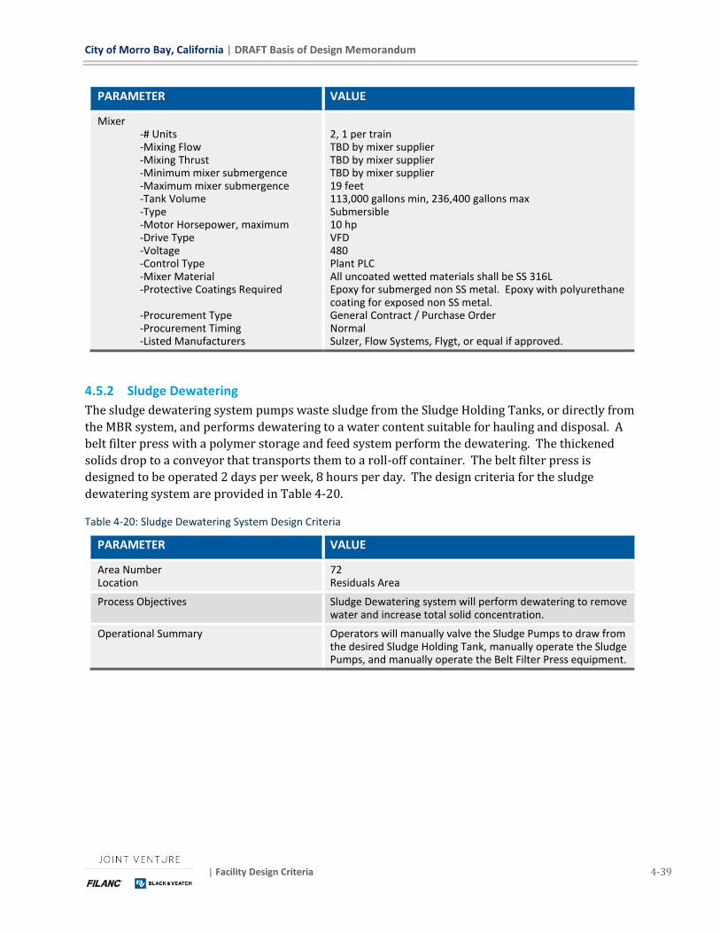
City of Morro Bay, California | DRAFT Basis of Design Memorandum
| Facility Design Criteria 4-39
PARAMETER VALUE
Mixer -# Units -Mixing Flow -Mixing Thrust -Minimum mixer submergence -Maximum mixer submergence -Tank Volume -Type -Motor Horsepower, maximum -Drive Type -Voltage -Control Type -Mixer Material -Protective Coatings Required -Procurement Type -Procurement Timing -Listed Manufacturers
2, 1 per train TBD by mixer supplier TBD by mixer supplier TBD by mixer supplier 19 feet 113,000 gallons min, 236,400 gallons max Submersible 10 hp VFD 480 Plant PLC All uncoated wetted materials shall be SS 316L Epoxy for submerged non SS metal. Epoxy with polyurethane coating for exposed non SS metal. General Contract / Purchase Order Normal Sulzer, Flow Systems, Flygt, or equal if approved.
4.5.2 Sludge Dewatering
The sludge dewatering system pumps waste sludge from the Sludge Holding Tanks, or directly from
the MBR system, and performs dewatering to a water content suitable for hauling and disposal. A
belt filter press with a polymer storage and feed system perform the dewatering. The thickened
solids drop to a conveyor that transports them to a roll-off container. The belt filter press is
designed to be operated 2 days per week, 8 hours per day. The design criteria for the sludge
dewatering system are provided in Table 4-20.
Table 4-20: Sludge Dewatering System Design Criteria
PARAMETER VALUE
Area Number Location
72 Residuals Area
Process Objectives Sludge Dewatering system will perform dewatering to remove water and increase total solid concentration.
Operational Summary Operators will manually valve the Sludge Pumps to draw from the desired Sludge Holding Tank, manually operate the Sludge Pumps, and manually operate the Belt Filter Press equipment.
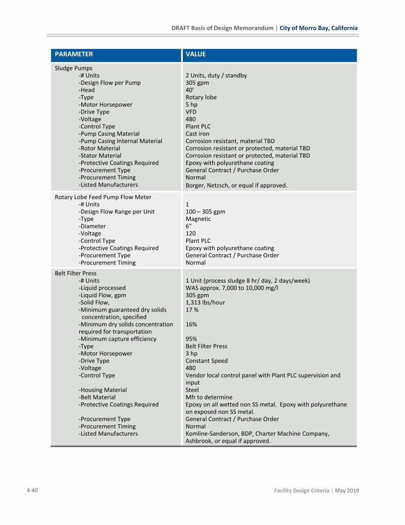
DRAFT Basis of Design Memorandum | City of Morro Bay, California
4-40 Facility Design Criteria | May 2019
PARAMETER VALUE
Sludge Pumps -# Units -Design Flow per Pump -Head -Type -Motor Horsepower -Drive Type -Voltage -Control Type -Pump Casing Material -Pump Casing Internal Material -Rotor Material -Stator Material -Protective Coatings Required -Procurement Type -Procurement Timing -Listed Manufacturers
2 Units, duty / standby 305 gpm 40' Rotary lobe 5 hp VFD 480 Plant PLC Cast iron Corrosion resistant, material TBD Corrosion resistant or protected, material TBD Corrosion resistant or protected, material TBD Epoxy with polyurethane coating General Contract / Purchase Order Normal Borger, Netzsch, or equal if approved.
Rotary Lobe Feed Pump Flow Meter -# Units -Design Flow Range per Unit -Type -Diameter -Voltage -Control Type -Protective Coatings Required -Procurement Type -Procurement Timing
1 100 – 305 gpm Magnetic 6" 120 Plant PLC Epoxy with polyurethane coating General Contract / Purchase Order Normal
Belt Filter Press -# Units -Liquid processed -Liquid Flow, gpm -Solid Flow, -Minimum guaranteed dry solids concentration, specified -Minimum dry solids concentration required for transportation -Minimum capture efficiency -Type -Motor Horsepower -Drive Type -Voltage -Control Type -Housing Material -Belt Material -Protective Coatings Required -Procurement Type -Procurement Timing -Listed Manufacturers
1 Unit (process sludge 8 hr/ day, 2 days/week) WAS approx. 7,000 to 10,000 mg/l 305 gpm 1,313 lbs/hour 17 % 16% 95% Belt Filter Press 3 hp Constant Speed 480 Vendor local control panel with Plant PLC supervision and input Steel Mfr to determine Epoxy on all wetted non SS metal. Epoxy with polyurethane on exposed non SS metal. General Contract / Purchase Order Normal Komline-Sanderson, BDP, Charter Machine Company, Ashbrook, or equal if approved.

City of Morro Bay, California | DRAFT Basis of Design Memorandum
| Facility Design Criteria 4-41
PARAMETER VALUE
Conveyor -# Units
-Design Flow per Unit -Type -Diameter -Motor Horsepower, ea -Drive Type -Voltage -Control Type -Wetted Components Material -Protective Coatings Required -Procurement Type -Procurement Timing -Listed Manufacturers
1 angled conveyor to lift solids from belt filter press 1 horizontal conveyor with 2 electric knife gate valves above dumpster 3 cfm Shaftless Screw TBD" 1.5 hp Constant Speed 480 Part of Belt Filter Press Control Panel SS 316 Epoxy with Polyurethane on all exposed non-SS metals General Contract / Purchase Order Normal JDV, Custom Conveyor Corporation, or equal if approved.
4.5.3 SAFE System
The SAFE system uses cloth media filtration to provide side-stream treatment of peak flows for
blending with effluent from the MBR system and discharge to the ocean. The SAFE system
diversion box sends flow exceeding the MBR capacity to the SAFE system by gravity. A concrete
tank, called the SAFE Settle, is located upstream of the SAFE Filter. The SAFE Settle basin captures
and equalizes peak event flows. Many of the smaller peak flow events will not completely fill the
SAFE Settle basin and therefore would not go to the SAFE Filter System. Water from these events
will be pumped back to the headworks for treatment when plant flows have decreased.
In larger peak flow events, water fills the SAFE Settle basin until it passes over a weir and flows to
the SAFE Filter System for filtration treatment. During this operation, the Safe Settle basin provides
sedimentation treatment upstream of the Safe Filter System. Effluent from the SAFE Filter System
is routed to the Outfall Balancing Tank where it is blended with MBR effluent and pumped by the
Outfall Pump Station to the Outfall Disinfection Pipeline Contactor and then onto the Ocean Outfall.
The design criteria for the SAFE system are provided in Table 4-21 below.
Table 4-21: SAFE System Design Criteria
PARAMETER VALUE
Area Number Location
73 Residuals Area
Process Objectives Flows in excess of the BNR-MBR capacity will l be treated with an auxiliary treatment system consisting of settling in an EQ tank and filtration. Effluent from this system will be routed to Outfall Pump Station.

DRAFT Basis of Design Memorandum | City of Morro Bay, California
4-42 Facility Design Criteria | May 2019
PARAMETER VALUE
Operational Summary Excess plant influent flows passively overflow the SAFE Diversion Weir at the SAFE Diversion Box and flow by gravity to the SAFE Settle Tank. This tank provides equalization and settling before flow passively overflows to the SAFE Filter System by gravity. The SAFE Filter system filters the water by gravity. The filtered effluent flows to the Outfall Pump station by gravity. The SAFE filter system includes a backwash drive and pumps which start automatically as required during operation of the SAFE Filter system. Backwash waste is pump to the Fine Screens Influent for treatment by the BNR system.
SAFE Settle -# Units -Design Flow Range per Unit -Type -Operating Volume -Dimensions, Length x Width -Average Sidewater Depth -Effluent Weir Length -Protective Coatings Required
(Located in area 71) 1 0 to 6.26 MGD Concrete tank 99,600 gallons 38'-10" x 17'-0" 20'-2" 13'-0" None
SAFE Filter Inlet Flow Meter -# Units -Design Flow Range per Unit -Type -Diameter -Voltage -Control Type -Protective Coatings Required -Procurement Type -Procurement Timing
1 0 to 6.26 MGD Magnetic 16" 120 Plant PLC Epoxy with polyurethane coating General Contract / Purchase Order Normal
SAFE Filter -# Units -Design Flow per Unit -Total System Design Capacity -Type -Total filtration area -Filter media size -Backwash Shoe Rotation Motor Horsepower -Drive type -Voltage -Control Type -Equipment Housing Material -Tank Interior Protective Coatings Required -Tank Exterior Protective Coatings Required -Procurement Type -Procurement Timing -Listed Manufacturers (OEM)
1 6.26 MGD 6.26 MGD Cloth Media Disc Filter 1,076 square feet 5 micron 2 hp Constant Speed 480 Local vendor control panel with Plant PLC supervision and input Steel Epoxy Epoxy with polyurethane Disc Filtration System Package Early, submittals for 90% design Aqua-Aerobic Systems Inc., Veolia or equal if approved.
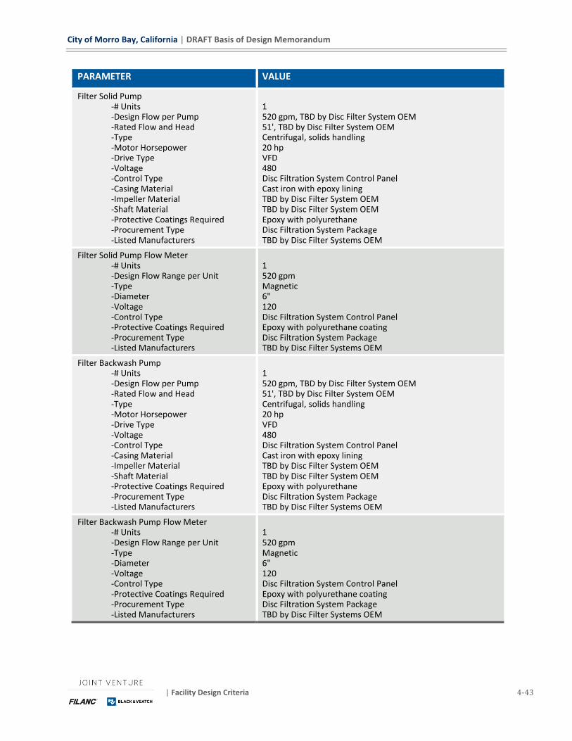
City of Morro Bay, California | DRAFT Basis of Design Memorandum
| Facility Design Criteria 4-43
PARAMETER VALUE
Filter Solid Pump -# Units -Design Flow per Pump -Rated Flow and Head -Type -Motor Horsepower -Drive Type -Voltage -Control Type -Casing Material -Impeller Material -Shaft Material -Protective Coatings Required -Procurement Type -Listed Manufacturers
1 520 gpm, TBD by Disc Filter System OEM 51', TBD by Disc Filter System OEM Centrifugal, solids handling 20 hp VFD 480 Disc Filtration System Control Panel Cast iron with epoxy lining TBD by Disc Filter System OEM TBD by Disc Filter System OEM Epoxy with polyurethane Disc Filtration System Package TBD by Disc Filter Systems OEM
Filter Solid Pump Flow Meter -# Units -Design Flow Range per Unit -Type -Diameter -Voltage -Control Type -Protective Coatings Required -Procurement Type -Listed Manufacturers
1 520 gpm Magnetic 6" 120 Disc Filtration System Control Panel Epoxy with polyurethane coating Disc Filtration System Package TBD by Disc Filter Systems OEM
Filter Backwash Pump -# Units -Design Flow per Pump -Rated Flow and Head -Type -Motor Horsepower -Drive Type -Voltage -Control Type -Casing Material -Impeller Material -Shaft Material -Protective Coatings Required -Procurement Type -Listed Manufacturers
1 520 gpm, TBD by Disc Filter System OEM 51', TBD by Disc Filter System OEM Centrifugal, solids handling 20 hp VFD 480 Disc Filtration System Control Panel Cast iron with epoxy lining TBD by Disc Filter System OEM TBD by Disc Filter System OEM Epoxy with polyurethane Disc Filtration System Package TBD by Disc Filter Systems OEM
Filter Backwash Pump Flow Meter -# Units -Design Flow Range per Unit -Type -Diameter -Voltage -Control Type -Protective Coatings Required -Procurement Type -Listed Manufacturers
1 520 gpm Magnetic 6" 120 Disc Filtration System Control Panel Epoxy with polyurethane coating Disc Filtration System Package TBD by Disc Filter Systems OEM
DRAFT Basis of Design Memorandum | City of Morro Bay, California
4-44 Facility Design Criteria | May 2019
4.6 CHEMICAL STORAGE AND FEED FACILITIES – AREA 90 The following chemicals will be used as part of the Morro Bay WRF.
◼ Antiscalant (Threshold Inhibitor) – Added to the RO system feed water to minimize inorganic
scaling on the membranes.
◼ Citric Acid – Used for periodic cleaning of both the RO and MBR membranes; Used to neutralize
cleaning solutions.
◼ Polymer – Added to the sludge fed to the Belt Filter Press to assist in cake formation.
◼ Sodium Bisulfite – Added to remove residual chlorine from flow sent to the ocean outfall.
◼ Sodium Hydroxide – Used for pH control and alkalinity addition in the BNR feed and product
water; used for periodic cleaning of both the RO and MBR membranes and neutralization of
cleaning solutions.
◼ Sodium Hypochlorite – Used for bio-growth control and disinfection purposes throughout the
plant; used for periodic cleaning of membranes; used as an oxidizing agent in the UV system.
◼ Sulfuric Acid – Added to the RO feed water to control pH and help minimize scaling; added to the
UV AOP feed to control pH and ensure free chlorine is in the hypochlorous acid form.
◼ Liquid Ammonium Sulfate (LAS) – FUTURE CHEMICAL. Space and spare conduits are furnished
to support addition of a LAS feed system in the future. The design of this plant is to operate the
BNR system to leave ammonia carry-over sufficient for use in monochloramination of RO Feed
water for biofouling control. If the City choses at a later date to not operate the BNR system in
this way, addition of the LAS system would be required.
These chemicals listed above (with the exception of polymer) will be stored in a centralized storage
and feed facility located near the middle of the plant site. This facility will be covered by a roof
canopy to shade the area from the sun and reduce the amount of rain water that can enter the
equipment area. Polymer will be stored near the belt press located in the Dewatering Area.
The Main Chemical Facility will have vehicular access as it located adjacent to the main access road
through site. Deliveries to the facility will be either via bulk tanker truck or as liquids delivered in
totes. Bulk tanker trucks will be able to pull off the main road and park adjacent to the Chemical
Facility for unloading bulk chemical. The tanker truck pull off location will be slightly depressed
such that in the event of a tanker leak, chemical will be directed to a sump so that it can be properly
disposed of. Tote containment will be on the road side of the facility so that totes can be placed on
their secondary containment tubs via a forklift from the road.
The tables below represent the design criteria for the chemical feed systems. Storage volumes have
been designed to be sufficient for 15 days of operation under average conditions. Most of the tables
below contain information on how long the selected volume of chemical will last under worst case
(max flow at max chemical dose) operation for information.
4.6.1 Antiscalant
One antiscalant system will be provided to feed chemical upstream of the RO system. Antiscalant
will be delivered and stored in a standard 330-gallon Intermediate Bulk Container (IBC) which will
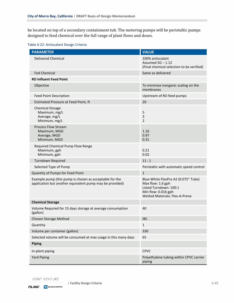
City of Morro Bay, California | DRAFT Basis of Design Memorandum
| Facility Design Criteria 4-45
be located on top of a secondary containment tub. The metering pumps will be peristaltic pumps
designed to feed chemical over the full range of plant flows and doses.
Table 4-22: Antiscalant Design Criteria
PARAMETER VALUE
Delivered Chemical 100% antiscalant Assumed SG – 1.12 (Final chemical selection to be verified)
Fed Chemical Same as delivered
RO Influent Feed Point
Objective To minimize inorganic scaling on the membranes
Feed Point Description Upstream of RO feed pumps
Estimated Pressure at Feed Point, ft 20
Chemical Dosage Maximum, mg/L Average, mg/L Minimum, mg/L
5 3 2
Process Flow Stream Maximum, MGD Average, MGD Minimum, MGD
1.16 0.97 0.31
Required Chemical Pump Flow Range Maximum, gph Minimum, gph
0.21 0.02
Turndown Required 11 : 1
Selected Type of Pump Peristaltic with automatic speed control
Quantity of Pumps for Feed Point 1
Example pump (this pump is chosen as acceptable for the application but another equivalent pump may be provided)
Blue-White FlexPro A2 (0.075” Tube) Max flow: 1.6 gph Listed Turndown: 100:1 Min flow: 0.016 gph Wetted Materials: Flex-A-Prene
Chemical Storage
Volume Required for 15 days storage at average consumption (gallon)
40
Chosen Storage Method IBC
Quantity 1
Volume per container (gallon) 330
Selected volume will be consumed at max usage in this many days 65
Piping
In-plant piping CPVC
Yard Piping Polyethylene tubing within CPVC carrier piping
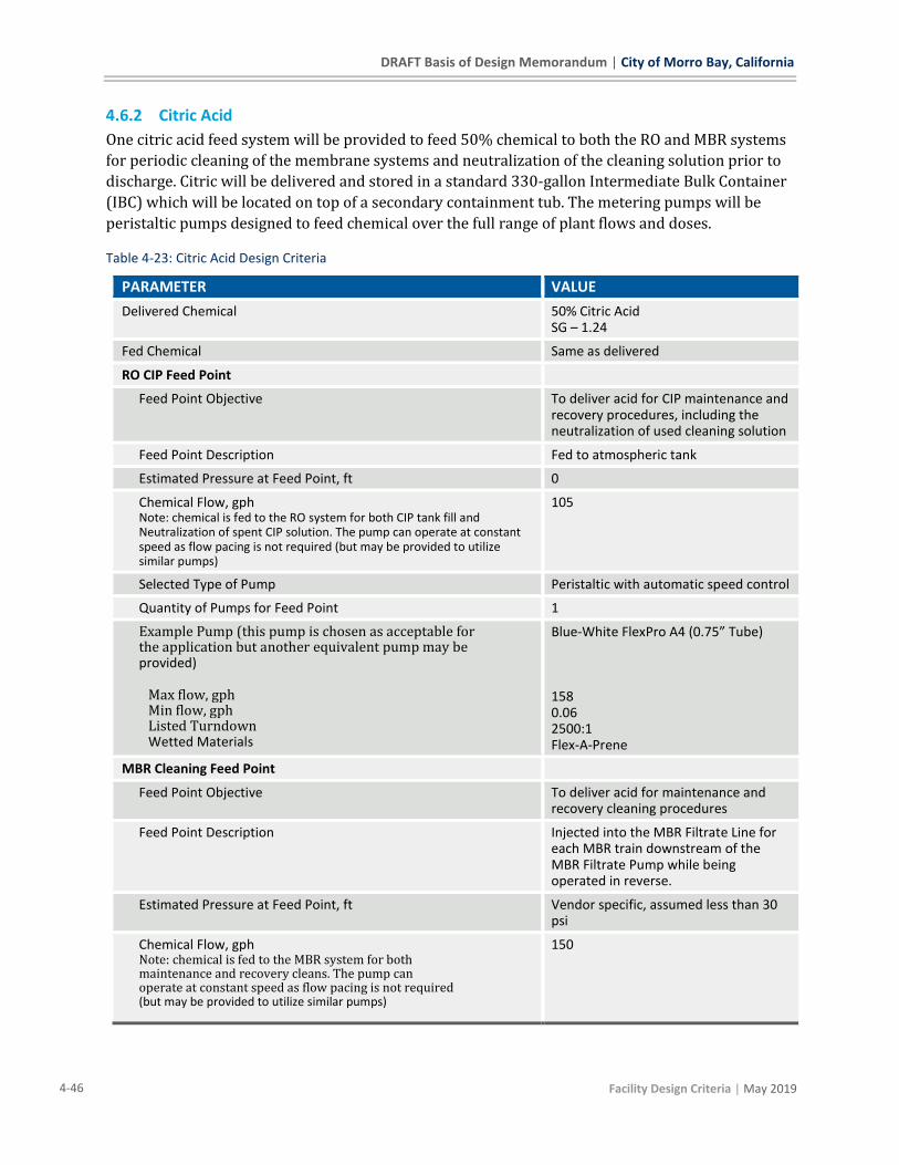
DRAFT Basis of Design Memorandum | City of Morro Bay, California
4-46 Facility Design Criteria | May 2019
4.6.2 Citric Acid
One citric acid feed system will be provided to feed 50% chemical to both the RO and MBR systems
for periodic cleaning of the membrane systems and neutralization of the cleaning solution prior to
discharge. Citric will be delivered and stored in a standard 330-gallon Intermediate Bulk Container
(IBC) which will be located on top of a secondary containment tub. The metering pumps will be
peristaltic pumps designed to feed chemical over the full range of plant flows and doses.
Table 4-23: Citric Acid Design Criteria
PARAMETER VALUE
Delivered Chemical 50% Citric Acid SG – 1.24
Fed Chemical Same as delivered
RO CIP Feed Point
Feed Point Objective To deliver acid for CIP maintenance and recovery procedures, including the neutralization of used cleaning solution
Feed Point Description Fed to atmospheric tank
Estimated Pressure at Feed Point, ft 0
Chemical Flow, gph Note: chemical is fed to the RO system for both CIP tank fill and Neutralization of spent CIP solution. The pump can operate at constant speed as flow pacing is not required (but may be provided to utilize similar pumps)
105
Selected Type of Pump Peristaltic with automatic speed control
Quantity of Pumps for Feed Point 1
Example Pump (this pump is chosen as acceptable for the application but another equivalent pump may be provided)
Max flow, gph Min flow, gph Listed Turndown Wetted Materials
Blue-White FlexPro A4 (0.75” Tube) 158 0.06 2500:1 Flex-A-Prene
MBR Cleaning Feed Point
Feed Point Objective To deliver acid for maintenance and recovery cleaning procedures
Feed Point Description Injected into the MBR Filtrate Line for each MBR train downstream of the MBR Filtrate Pump while being operated in reverse.
Estimated Pressure at Feed Point, ft Vendor specific, assumed less than 30 psi
Chemical Flow, gph Note: chemical is fed to the MBR system for both maintenance and recovery cleans. The pump can operate at constant speed as flow pacing is not required (but may be provided to utilize similar pumps)
150
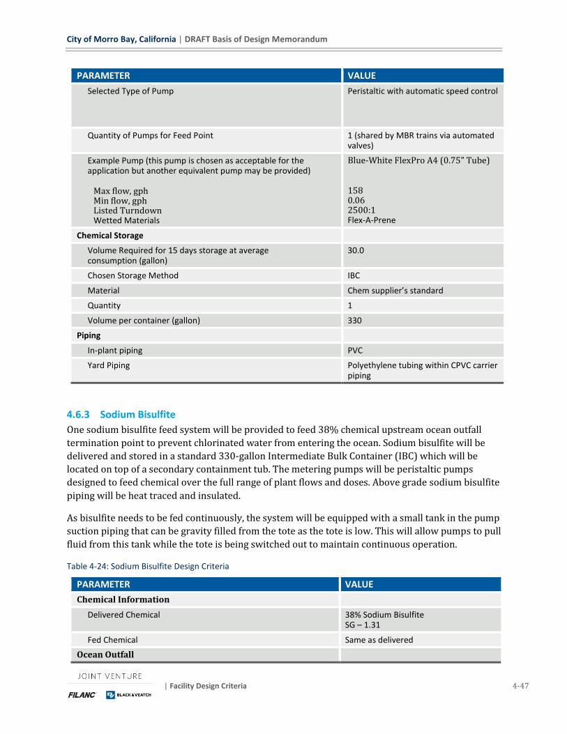
City of Morro Bay, California | DRAFT Basis of Design Memorandum
| Facility Design Criteria 4-47
PARAMETER VALUE
Selected Type of Pump Peristaltic with automatic speed control
Quantity of Pumps for Feed Point 1 (shared by MBR trains via automated valves)
Example Pump (this pump is chosen as acceptable for the application but another equivalent pump may be provided) Max flow, gph Min flow, gph Listed Turndown Wetted Materials
Blue-White FlexPro A4 (0.75” Tube) 158 0.06 2500:1 Flex-A-Prene
Chemical Storage
Volume Required for 15 days storage at average consumption (gallon)
30.0
Chosen Storage Method IBC
Material Chem supplier’s standard
Quantity 1
Volume per container (gallon) 330
Piping
In-plant piping PVC
Yard Piping Polyethylene tubing within CPVC carrier piping
4.6.3 Sodium Bisulfite
One sodium bisulfite feed system will be provided to feed 38% chemical upstream ocean outfall
termination point to prevent chlorinated water from entering the ocean. Sodium bisulfite will be
delivered and stored in a standard 330-gallon Intermediate Bulk Container (IBC) which will be
located on top of a secondary containment tub. The metering pumps will be peristaltic pumps
designed to feed chemical over the full range of plant flows and doses. Above grade sodium bisulfite
piping will be heat traced and insulated.
As bisulfite needs to be fed continuously, the system will be equipped with a small tank in the pump
suction piping that can be gravity filled from the tote as the tote is low. This will allow pumps to pull
fluid from this tank while the tote is being switched out to maintain continuous operation.
Table 4-24: Sodium Bisulfite Design Criteria
PARAMETER VALUE
Chemical Information
Delivered Chemical 38% Sodium Bisulfite SG – 1.31
Fed Chemical Same as delivered
Ocean Outfall
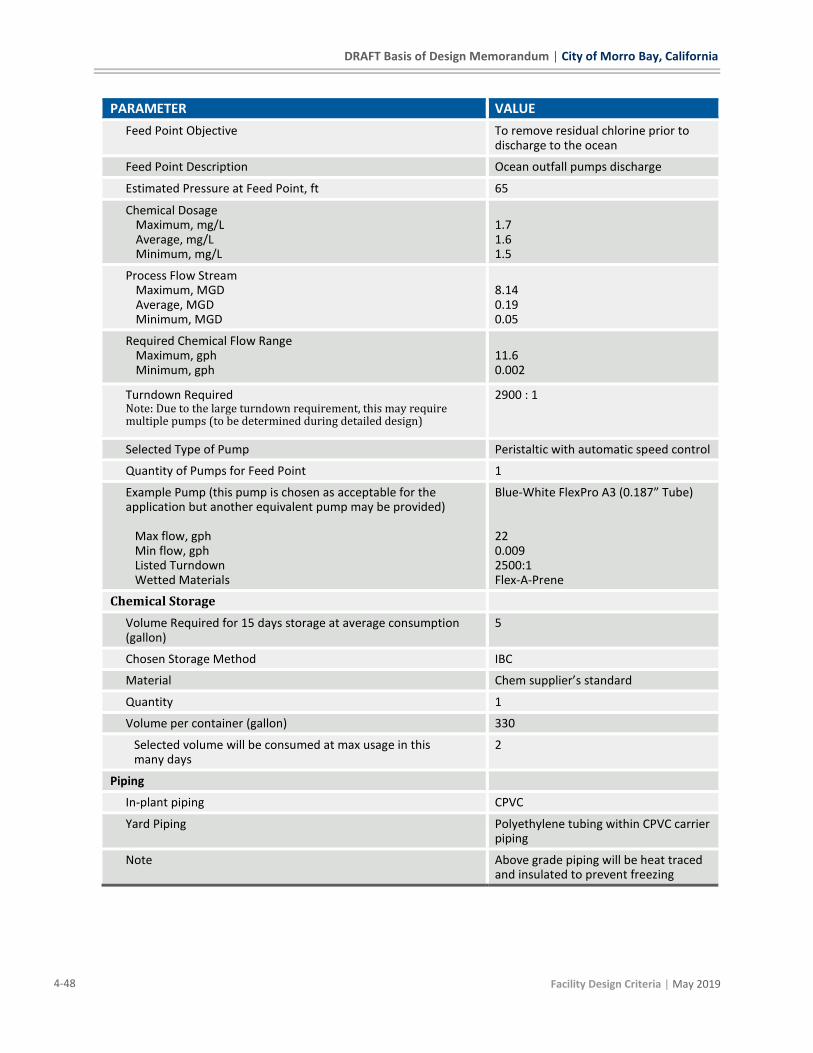
DRAFT Basis of Design Memorandum | City of Morro Bay, California
4-48 Facility Design Criteria | May 2019
PARAMETER VALUE
Feed Point Objective To remove residual chlorine prior to discharge to the ocean
Feed Point Description Ocean outfall pumps discharge
Estimated Pressure at Feed Point, ft 65
Chemical Dosage Maximum, mg/L Average, mg/L Minimum, mg/L
1.7 1.6 1.5
Process Flow Stream Maximum, MGD Average, MGD Minimum, MGD
8.14 0.19 0.05
Required Chemical Flow Range Maximum, gph Minimum, gph
11.6 0.002
Turndown Required Note: Due to the large turndown requirement, this may require multiple pumps (to be determined during detailed design)
2900 : 1
Selected Type of Pump Peristaltic with automatic speed control
Quantity of Pumps for Feed Point 1
Example Pump (this pump is chosen as acceptable for the application but another equivalent pump may be provided) Max flow, gph Min flow, gph Listed Turndown Wetted Materials
Blue-White FlexPro A3 (0.187” Tube) 22 0.009 2500:1 Flex-A-Prene
Chemical Storage
Volume Required for 15 days storage at average consumption (gallon)
5
Chosen Storage Method IBC
Material Chem supplier’s standard
Quantity 1
Volume per container (gallon) 330
Selected volume will be consumed at max usage in this many days
2
Piping
In-plant piping CPVC
Yard Piping Polyethylene tubing within CPVC carrier piping
Note Above grade piping will be heat traced and insulated to prevent freezing

City of Morro Bay, California | DRAFT Basis of Design Memorandum
| Facility Design Criteria 4-49
4.6.4 Sodium Hydroxide
One hydroxide bulk storage tank will be provided to store 25 percent solution. This solution
strength was selected to prevent the need for heat tracing the tank and piping while still
maintaining a reasonable volume of storage. This tank will supply all the pumps which feed
hydroxide throughout the site. The tank is sized to hold 15 days of storage or approximately one
full tanker delivery, whichever is greater. The metering pumps will be peristaltic pumps designed
to feed chemical over the full range of plant flows and doses.
Table 4-25: Sodium Hydroxide Design Criteria
PARAMETER VALUE
Chemical Information
Delivered Chemical 25% Sodium Hydroxide SG 1.25
Fed Chemical Same as delivered
RO CIP Feed Point
Feed Point Objective To deliver base for CIP maintenance and recovery procedures, including the neutralization of used cleaning solution
Feed Point Description Fed to Atmospheric tank
Estimated Pressure at Feed Point, ft 0
Chemical Flow, gph Note: chemical is fed to the RO system for both CIP tank fill and Neutralization of spent CIP solution. The pump can operate at constant speed as flow pacing is not required (but may be provided to utilize similar pumps)
130
Selected Type of Pump Peristaltic with automatic speed control
Quantity of Pumps for Feed Point 1
Example pump (this pump is chosen as acceptable for the application but another equivalent pump may be provided) Max flow, gph Min flow, gph Listed Turndown Wetted Materials
Blue-White FlexPro A4 (0.187” Tube) 158 0.06 2500:1 Flex-A-Prene
BNR Feed Point
Feed Point Objective To increase alkalinity and control pH in the BNR basins
Feed Point Description Ahead of MBR splitter box
Estimated Pressure at Feed Point, ft 10
Chemical Dosage Maximum, mg/L Average, mg/L Minimum, mg/L
30 5 0.5

DRAFT Basis of Design Memorandum | City of Morro Bay, California
4-50 Facility Design Criteria | May 2019
PARAMETER VALUE
Process Flow Stream Maximum, MGD Average, MGD Minimum, MGD
1.88 1.16 0.84
Required Chemical Flow Range Maximum, gph Minimum, gph
9.0 0.1
Turndown Required 90 : 1
Selected Type of Pump Peristaltic with automatic speed control
Quantity of Pumps for Feed Point 1
Example Pump (this pump is chosen as acceptable for the application but another equivalent pump may be provided) Max flow, gph Min flow, gph Listed Turndown Wetted Materials
Blue-White FlexPro A2 (0.187” Tube) 19.3 0.19 100:1 Flex-A-Prene
Product Water Feed Point
Feed Point Objective To control pH in the product water
Feed Point Description Product water tank inlet
Estimated Pressure at Feed Point, ft 40
Chemical Dosage Maximum, mg/L Average, mg/L Minimum, mg/L
2.0 2.0 2.0
Process Flow Stream Maximum, MGD Average, MGD Minimum, MGD
0.80 0.78 0.26
Required Chemical Flow Range Maximum, gph Minimum, gph
0.21 0.07
Turndown Required 3 : 1
Selected Type of Pump Peristaltic with automatic speed control
Quantity of Pumps for Feed Point 1
Example Pump (this pump is chosen as acceptable for the application but another equivalent pump may be provided) Max flow, gph Min flow, gph Listed Turndown Wetted Materials
Blue-White FlexPro A2 (0.075” Tube) 1.6 0.02 100:1 Flex-A-Prene
Chemical Storage
Volume Required for 15 days storage (gallon) ~600

City of Morro Bay, California | DRAFT Basis of Design Memorandum
| Facility Design Criteria 4-51
PARAMETER VALUE
Chosen Storage Method Vertical bulk storage tank sized for the estimated amount used or a full tanker, whichever is greater
Tanker delivery volume 4200 gallon
Material FRP or PE
Quantity 1
Approximate selected tank dimensions 10’ diameter x 10’ side shell height
Volume of selected tank 5800 gallon
Selected volume will be consumed at max usage in this many days Note: The storage requirements listed are based on annual average use. However, during maximum month, the alkalinity requirements for the BNR process significantly increase (8x higher). Moreover, the annual average requirements can significantly change based on influent raw alkalinity (assumed to be 275 mg CaCO3 in analysis). Tanker delivery was selected to ensure adequate storage for 15 days at annual average and maximum month conditions.
140
Piping
In-plant piping Carbon Steel
Yard Piping Polyethylene tubing within CPVC carrier piping
4.6.5 Sodium Hypochlorite
One hypochlorite bulk storage tank will be provided to store 12.5 percent solution. As Hypochlorite
can degrade over time, the values used to calculate pump sizes and storage volumes were assumed
to be at less than full strength to ensure adequate capacity. The storage tank is sized to hold 15 days
of storage or approximately one full tanker delivery, whichever is greater. The metering pumps will
be peristaltic pumps designed to feed chemical over the full range of plant flows and doses.
Table 4-26: Sodium Hypochlorite Design Criteria
PARAMETER VALUE
Chemical Information
Delivered Chemical 12.5% Sodium Hypochlorite SG 1.18
Fed Chemical Same as delivered
MBR Cleaning Feed Point
Feed Point Objective To perform maintenance and recovery cleaning procedures
Feed Point Description Injected into the MBR Filtrate Line for each MBR train downstream of the MBR Filtrate Pump while being operated in reverse.
Estimated Pressure at Feed Point, ft Vendor specific, assumed less than 60 psi

DRAFT Basis of Design Memorandum | City of Morro Bay, California
4-52 Facility Design Criteria | May 2019
PARAMETER VALUE
Chemical Flow, gph Note: chemical is fed to the MBR system for both maintenance and recovery cleans. The pump can operate at constant speed as flow pacing is not required (but may be provided to utilize similar pumps)
150
Selected Type of Pump Peristaltic with automatic speed control
Quantity of Pumps for Feed Point 1 (shared by each MBR train via automated valve)
Example Pump (this pump is chosen as acceptable for the application but another equivalent pump may be provided) Max flow, gph Min flow, gph Listed Turndown Wetted Materials
Blue-White FlexPro A4 (0.75” Tube) 158 0.06 2500:1 Flex-A-Prene
Ocean Outfall Feed Point
Feed Point Objective To disinfect flow from the Outfall Balancing Tank
Feed Point Description Outfall pump discharge
Estimated Pressure at Feed Point, ft 65
Chemical Dosage Maximum, mg/L Average, mg/L Minimum, mg/L
20 5 3
Process Flow Stream Maximum, MGD Average, MGD Minimum, MGD
8.14 0.97 0.50
Required Chemical Flow Range Maximum, gph Minimum, gph
65 0.6
Total Turndown Required 110 : 1
Selected Type of Pump Peristaltic with automatic speed control
Quantity of Pumps for Feed Point 1
Example Pump (this pump is chosen as acceptable for the application but another equivalent pump may be provided) Max flow, gph Min flow, gph Listed Turndown Wetted Materials
Blue-White FlexPro A4 (0.75” Tube) 158.5 0.06 2500:1 Flex-A-Prene
RO Concentrate Feed Point
Feed Point Objective To disinfect RO Concentrate
Feed Point Description Outfall Balancing Tank inlet
Estimated Pressure at Feed Point, ft 20
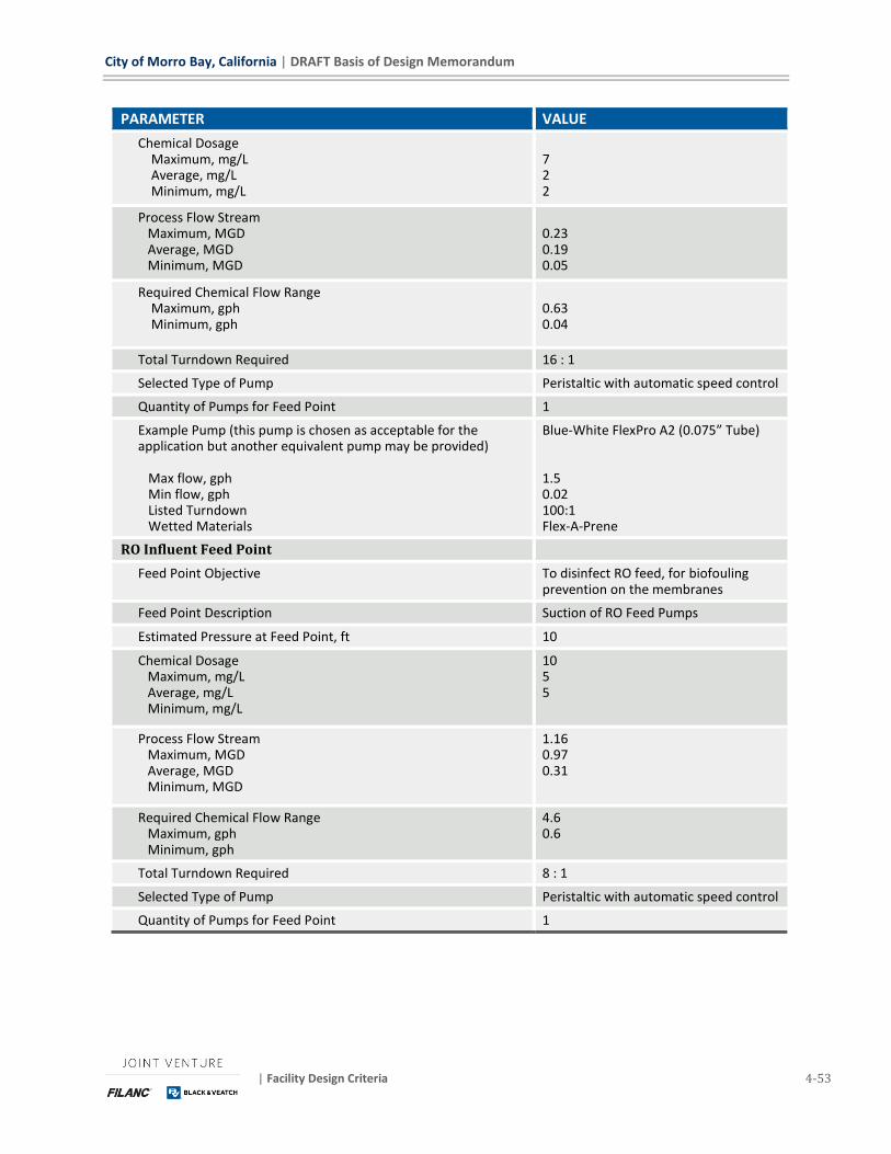
City of Morro Bay, California | DRAFT Basis of Design Memorandum
| Facility Design Criteria 4-53
PARAMETER VALUE
Chemical Dosage Maximum, mg/L Average, mg/L Minimum, mg/L
7 2 2
Process Flow Stream Maximum, MGD Average, MGD Minimum, MGD
0.23 0.19 0.05
Required Chemical Flow Range Maximum, gph Minimum, gph
0.63 0.04
Total Turndown Required 16 : 1
Selected Type of Pump Peristaltic with automatic speed control
Quantity of Pumps for Feed Point 1
Example Pump (this pump is chosen as acceptable for the application but another equivalent pump may be provided) Max flow, gph Min flow, gph Listed Turndown Wetted Materials
Blue-White FlexPro A2 (0.075” Tube) 1.5 0.02 100:1 Flex-A-Prene
RO Influent Feed Point
Feed Point Objective To disinfect RO feed, for biofouling prevention on the membranes
Feed Point Description Suction of RO Feed Pumps
Estimated Pressure at Feed Point, ft 10
Chemical Dosage Maximum, mg/L Average, mg/L Minimum, mg/L
10 5 5
Process Flow Stream Maximum, MGD Average, MGD Minimum, MGD
1.16 0.97 0.31
Required Chemical Flow Range Maximum, gph Minimum, gph
4.6 0.6
Total Turndown Required 8 : 1
Selected Type of Pump Peristaltic with automatic speed control
Quantity of Pumps for Feed Point 1
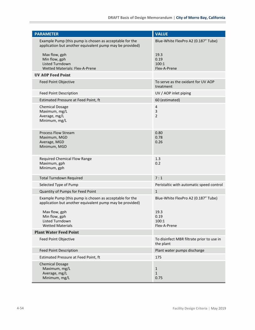
DRAFT Basis of Design Memorandum | City of Morro Bay, California
4-54 Facility Design Criteria | May 2019
PARAMETER VALUE
Example Pump (this pump is chosen as acceptable for the application but another equivalent pump may be provided)
Max flow, gph Min flow, gph Listed Turndown Wetted Materials: Flex-A-Prene
Blue-White FlexPro A2 (0.187” Tube) 19.3 0.19 100:1 Flex-A-Prene
UV AOP Feed Point
Feed Point Objective To serve as the oxidant for UV AOP treatment
Feed Point Description UV / AOP inlet piping
Estimated Pressure at Feed Point, ft 60 (estimated)
Chemical Dosage Maximum, mg/L Average, mg/L Minimum, mg/L
4 3 2
Process Flow Stream Maximum, MGD Average, MGD Minimum, MGD
0.80 0.78 0.26
Required Chemical Flow Range Maximum, gph Minimum, gph
1.3 0.2
Total Turndown Required 7 : 1
Selected Type of Pump Peristaltic with automatic speed control
Quantity of Pumps for Feed Point 1
Example Pump (this pump is chosen as acceptable for the application but another equivalent pump may be provided) Max flow, gph Min flow, gph Listed Turndown Wetted Materials
Blue-White FlexPro A2 (0.187” Tube) 19.3 0.19 100:1 Flex-A-Prene
Plant Water Feed Point
Feed Point Objective To disinfect MBR filtrate prior to use in the plant
Feed Point Description Plant water pumps discharge
Estimated Pressure at Feed Point, ft 175
Chemical Dosage Maximum, mg/L Average, mg/L Minimum, mg/L
1 1 0.75
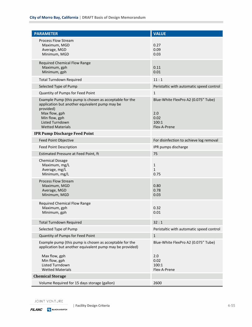
City of Morro Bay, California | DRAFT Basis of Design Memorandum
| Facility Design Criteria 4-55
PARAMETER VALUE
Process Flow Stream Maximum, MGD Average, MGD Minimum, MGD
0.27 0.09 0.03
Required Chemical Flow Range Maximum, gph Minimum, gph
0.11 0.01
Total Turndown Required 11 : 1
Selected Type of Pump Peristaltic with automatic speed control
Quantity of Pumps for Feed Point 1
Example Pump (this pump is chosen as acceptable for the application but another equivalent pump may be provided) Max flow, gph Min flow, gph Listed Turndown Wetted Materials
Blue-White FlexPro A2 (0.075” Tube) 2.0 0.02 100:1 Flex-A-Prene
IPR Pump Discharge Feed Point
Feed Point Objective For disinfection to achieve log removal
Feed Point Description IPR pumps discharge
Estimated Pressure at Feed Point, ft 75
Chemical Dosage Maximum, mg/L Average, mg/L Minimum, mg/L
1 1 0.75
Process Flow Stream Maximum, MGD Average, MGD Minimum, MGD
0.80 0.78 0.03
Required Chemical Flow Range Maximum, gph Minimum, gph
0.32 0.01
Total Turndown Required 32 : 1
Selected Type of Pump Peristaltic with automatic speed control
Quantity of Pumps for Feed Point 1
Example pump (this pump is chosen as acceptable for the application but another equivalent pump may be provided) Max flow, gph Min flow, gph Listed Turndown Wetted Materials
Blue-White FlexPro A2 (0.075” Tube) 2.0 0.02 100:1 Flex-A-Prene
Chemical Storage
Volume Required for 15 days storage (gallon) 2600
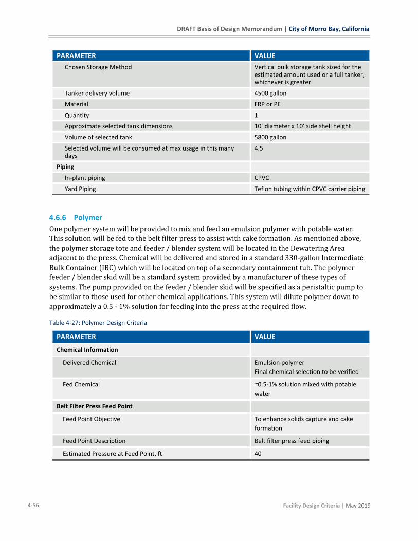
DRAFT Basis of Design Memorandum | City of Morro Bay, California
4-56 Facility Design Criteria | May 2019
PARAMETER VALUE
Chosen Storage Method Vertical bulk storage tank sized for the estimated amount used or a full tanker, whichever is greater
Tanker delivery volume 4500 gallon
Material FRP or PE
Quantity 1
Approximate selected tank dimensions 10’ diameter x 10’ side shell height
Volume of selected tank 5800 gallon
Selected volume will be consumed at max usage in this many days
4.5
Piping
In-plant piping CPVC
Yard Piping Teflon tubing within CPVC carrier piping
4.6.6 Polymer
One polymer system will be provided to mix and feed an emulsion polymer with potable water.
This solution will be fed to the belt filter press to assist with cake formation. As mentioned above,
the polymer storage tote and feeder / blender system will be located in the Dewatering Area
adjacent to the press. Chemical will be delivered and stored in a standard 330-gallon Intermediate
Bulk Container (IBC) which will be located on top of a secondary containment tub. The polymer
feeder / blender skid will be a standard system provided by a manufacturer of these types of
systems. The pump provided on the feeder / blender skid will be specified as a peristaltic pump to
be similar to those used for other chemical applications. This system will dilute polymer down to
approximately a 0.5 - 1% solution for feeding into the press at the required flow.
Table 4-27: Polymer Design Criteria
PARAMETER VALUE
Chemical Information
Delivered Chemical Emulsion polymer
Final chemical selection to be verified
Fed Chemical ~0.5-1% solution mixed with potable
water
Belt Filter Press Feed Point
Feed Point Objective To enhance solids capture and cake
formation
Feed Point Description Belt filter press feed piping
Estimated Pressure at Feed Point, ft 40

City of Morro Bay, California | DRAFT Basis of Design Memorandum
| Facility Design Criteria 4-57
PARAMETER VALUE
Chemical Usage
Maximum, lb / dry ton
Average, lb / dry ton
Minimum, lb / dry ton
30
30
25
Estimated Solids in Process Flow Stream
Maximum, dry ton / day
Average, dry ton / day
Minimum, dry ton / day
1.5
0.99
0.67
Required Chemical Flow Range
Maximum, gph
Minimum, gph
0.60
0.22
Turndown Required
Selected Type of Pump Peristaltic with automatic speed control
Quantity of Pumps for Feed Point 1
Example Pump (this pump is chosen as acceptable for the
application but another equivalent pump may be provided)
Max flow, gph
Min flow, gph
Listed Turndown
Wetted Materials
Blue-White FlexPro A2 (0.075” Tube)
2.0
0.02
100:1
To be Verified
Chemical Storage
Volume Required for 15 days storage (gallon) 15
Note: This is based on an assumed operating schedule of 8 hours
of press operation per day and 2 days of operation per week
Chosen Storage Method IBC
Material Chem supplier’s standard
Quantity 1
Volume per container (gallon) 330
Selected volume will be consumed at max usage in this many days
(assuming continuous press operation)
23
Piping
In-plant piping PVC
Yard Piping N/A – Polymer solution dosed at location stored
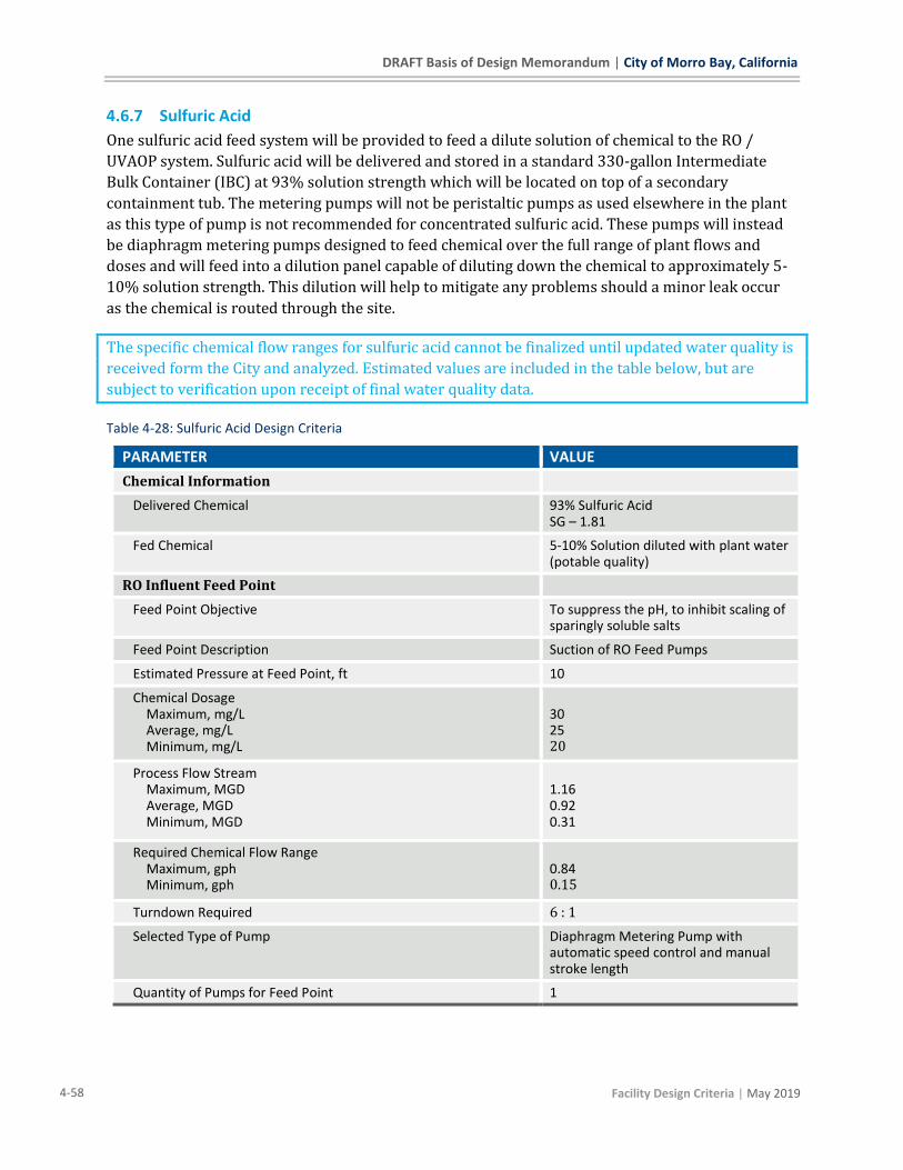
DRAFT Basis of Design Memorandum | City of Morro Bay, California
4-58 Facility Design Criteria | May 2019
4.6.7 Sulfuric Acid
One sulfuric acid feed system will be provided to feed a dilute solution of chemical to the RO /
UVAOP system. Sulfuric acid will be delivered and stored in a standard 330-gallon Intermediate
Bulk Container (IBC) at 93% solution strength which will be located on top of a secondary
containment tub. The metering pumps will not be peristaltic pumps as used elsewhere in the plant
as this type of pump is not recommended for concentrated sulfuric acid. These pumps will instead
be diaphragm metering pumps designed to feed chemical over the full range of plant flows and
doses and will feed into a dilution panel capable of diluting down the chemical to approximately 5-
10% solution strength. This dilution will help to mitigate any problems should a minor leak occur
as the chemical is routed through the site.
The specific chemical flow ranges for sulfuric acid cannot be finalized until updated water quality is
received form the City and analyzed. Estimated values are included in the table below, but are
subject to verification upon receipt of final water quality data.
Table 4-28: Sulfuric Acid Design Criteria
PARAMETER VALUE
Chemical Information
Delivered Chemical 93% Sulfuric Acid SG – 1.81
Fed Chemical 5-10% Solution diluted with plant water (potable quality)
RO Influent Feed Point
Feed Point Objective To suppress the pH, to inhibit scaling of sparingly soluble salts
Feed Point Description Suction of RO Feed Pumps
Estimated Pressure at Feed Point, ft 10
Chemical Dosage Maximum, mg/L Average, mg/L Minimum, mg/L
30 25 20
Process Flow Stream Maximum, MGD Average, MGD Minimum, MGD
1.16 0.92 0.31
Required Chemical Flow Range Maximum, gph Minimum, gph
0.84 0.15
Turndown Required 6 : 1
Selected Type of Pump Diaphragm Metering Pump with automatic speed control and manual stroke length
Quantity of Pumps for Feed Point 1
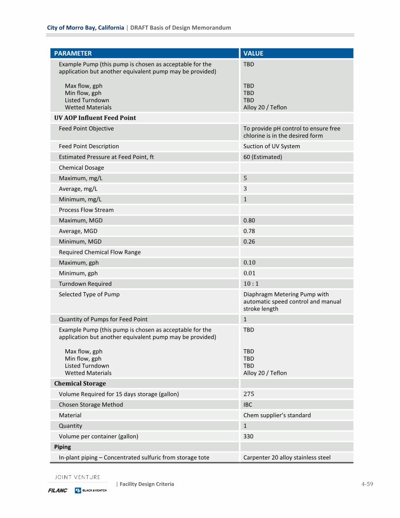
City of Morro Bay, California | DRAFT Basis of Design Memorandum
| Facility Design Criteria 4-59
PARAMETER VALUE
Example Pump (this pump is chosen as acceptable for the application but another equivalent pump may be provided) Max flow, gph Min flow, gph Listed Turndown Wetted Materials
TBD TBD TBD TBD Alloy 20 / Teflon
UV AOP Influent Feed Point
Feed Point Objective To provide pH control to ensure free chlorine is in the desired form
Feed Point Description Suction of UV System
Estimated Pressure at Feed Point, ft 60 (Estimated)
Chemical Dosage
Maximum, mg/L 5
Average, mg/L 3
Minimum, mg/L 1
Process Flow Stream
Maximum, MGD 0.80
Average, MGD 0.78
Minimum, MGD 0.26
Required Chemical Flow Range
Maximum, gph 0.10
Minimum, gph 0.01
Turndown Required 10 : 1
Selected Type of Pump Diaphragm Metering Pump with automatic speed control and manual stroke length
Quantity of Pumps for Feed Point 1
Example Pump (this pump is chosen as acceptable for the application but another equivalent pump may be provided) Max flow, gph Min flow, gph Listed Turndown Wetted Materials
TBD TBD TBD TBD Alloy 20 / Teflon
Chemical Storage
Volume Required for 15 days storage (gallon) 275
Chosen Storage Method IBC
Material Chem supplier’s standard
Quantity 1
Volume per container (gallon) 330
Piping
In-plant piping – Concentrated sulfuric from storage tote Carpenter 20 alloy stainless steel

DRAFT Basis of Design Memorandum | City of Morro Bay, California
4-60 Facility Design Criteria | May 2019
PARAMETER VALUE
In-plant piping – Downstream of dilution to handle heat generation
Teflon lined carbon steel
In-plant piping – Within RO building (dilute solution) CPVC
Yard Piping Teflon tubing within CPVC carrier piping
4.6.8 Liquid Ammonium Sulfate (FUTURE)
Space and spare conduits are furnished to support addition of a Liquid Ammonium Sulfate (LAS)
feed system in the future. This chemical would be used to react with sodium hypochlorite to form
monochloramine in order to carry a monochloramine residual through the RO system for biofouling
prevention. This system would be required if the City chooses to no longer operate the BNR to
leave carry-over ammonia for use in monochloramine formation.
City of Morro Bay, California | DRAFT Basis of Design Memorandum
| Civil Site Design Criteria 5-1
5 Civil Site Design Criteria This section provides the design criteria associated with site-civil elements of the WRF.
5.1 GRADING In general, on-site grading will be designed to meet the following:
◼ Maintain 2 percent or less slope in building access areas
◼ Maintain 4 percent or less slope in operational maneuvering areas. For example, between the
Maintenance Building and RO Building.
◼ Maintain 5 percent or less (preferably 4 percent or less) cross slope on roads.
◼ Maintain 8 percent or less running slope on site roads. A maximum 10 percent running slope is
permitted in special cases on straight runs.
◼ Maintain 2:1 slopes per Baseline Geotechnical Report, or flatter.
◼ Maintain 3:1 slopes in detention basins.
5.2 MAJOR YARD PIPING Plant process piping and site utility piping is shown on the Yard Piping Drawings. Pipes will be
bedded in sand or pea-gravel (to be determined) and backfilled with suitable onsite material.
Trench sections will be developed to clarify these requirements. Pipe materials will be as shown on
the Process & Instrumentation Drawings and as will be scheduled in the specification. The plant
makes wide use of PVC piping due to its excellent corrosion resistance and ease of installation.
5.2.1 Soil Corrosivity
The geotechnical work done to date indicates on-site materials are not corrosive. As such, no
special corrosion protection measures have been included beyond normal standard practice as
follows:
◼ Steel or ductile iron piping will have cement mortar or epoxy coating.
◼ Buried stainless steel will have pipe wrapping.
◼ Copper will be direct buried with poly bagging when running through concrete.
◼ PVC, CPVC, and HDPE pipes will be direct buried.
◼ Concrete structures do not require any coatings unless required to mitigate groundwater from
seeping into below grade dry structures.
5.3 DRAINAGE Stormwater management for the site will be based on the guidelines from the City of Morro Bay
Stormwater Guidance Manual for Low Impact Development & Post-Construction Requirements.
5.3.1 Hillside Drainage
All stormwater from the western hillside area is captured by a hillside toe swale along the west side
of the site. The flow in this swale is captured by catch basins and routed via culvert under the plant
site to the dry creek east of the site.
DRAFT Basis of Design Memorandum | City of Morro Bay, California
5-2 Civil Site Design Criteria | May 2019
5.3.2 Plant Site Drainage
All stormwater generated on-site will be captured in gutters, swales, and trenches to be routed to
the detention basins. The design is avoiding storm drain piping to the extent possible to minimize
long-term maintenance requirements. The detention basins will include some dead-volume at the
bottom to give plant operators some reaction time between flow entering the basin and being
discharged to the outlet.
The North Process Area, as shown on the drawings, drains to the North Stormwater Detention
Basin. Drainage is routed via sheet-flow on the roadways to a curb and gutter running on the
eastern side of the site. This gutter is intercepted by a trench with grating that routes the flow
across the road into the detention basin.
The North Detention Basin will be equipped an Outlet Control and Pumping Station. Normally this
structure will regulate the discharge rate from the detention basin to the dry creek east of the site
to be within the pre-development rate. This structure also allows the plant operators to manually
isolate this discharge and pump water from this basin to the plant headworks for treatment. This
feature is included with intent of using it to capture and treat first-flush water from the first storm
of the season.
The South Process Area, North Operations Area, and South Operations area, as shown on the
drawings, drain to the South Stormwater Detention Basin. Drainage is routed via sheet-flow on the
roadways to a curb and gutter running on the eastern side of the site. This gutter is intercepted by
a trench with grating that routes the flow across the road into the detention basin. An Outlet
Control Structure is provided to regulate the discharge rate from the detention basin to the dry
creek east of the site to be within the pre-development rate. A manual gate valve will be furnished
at this outlet to give the operators option to capture first flush flows without discharge to the dry-
stream. This structure will not be equipped with a pump.
5.4 EROSION CONTROL
5.4.1 Construction Phase Erosion Control
Silt and sediment collected by runoff during construction will be captured on site with temporary
silt fence along the border of the site adjacent to the dry creek. This silt fence will be maintained
through the construction to protect from construction debris.
5.4.2 Finished Site Erosion Control
All disturbed site areas that are not paved or landscaped will be hydroseeded per local
requirements. Drainage outlets will be furnished with rip rap to dissipate energy and prevent
erosion. Earthen swales will be hydroseeded, planted, or lined with rip-rap as required.
5.5 LANDSCAPING All improved areas within the site that are not concrete, asphalt, or landscaping will be crushed
rock.
Landscaping utilizing well-adapted drought-tolerant plantings will be furnished at the entrance
road and around the Operations Building. Landscaping plans will be furnished in drawings for the
60% or 90% design level submittals.
City of Morro Bay, California | DRAFT Basis of Design Memorandum
| Civil Site Design Criteria 5-3
Landscaping will be irrigated with reclaimed water from the Recycled Water Pump Station. Though
this water is treated and filtered to Title 22 Recycled Water requirements, it is not furnished with
adequate disinfection contact time to make it Title 22 compliant. All piping, valves, and sprinklers
using this water will be marked as recycled water not suitable for human consumption. Purple pipe
and fixtures will be furnished to the extent possible.
Additional landscaping details are provided in Section 3 of Exhibit B Scope of Work.
5.6 FENCING
5.6.1 WRF Site Fencing
The WRF Plant Site will be secured with a 6 ft galvanized steel chain-link fence with 3-strand barb
wire cap. A motorized gate is furnished to access the secured site.
The Operations Building are is secured with a combination of decorate fence where visible from
Highway 1 and chain-link fence in less visible locations. This area will be secured with a manually
closed gate which will be left open during weekday working hours and secured at all other times.
5.6.2 Parcel Fencing
The WRF does not occupy the entire land parcel. As of the authoring of this Basis of Design Report,
the City is in the land purchasing process for the WRF parcel. The City’s land purchase agreement
may require fencing of the entire parcel. If required, details of that fencing and its installation will
be coordinated and executed separately by the City.


City of Morro Bay, California | DRAFT Basis of Design Memorandum
| Structural Design Criteria 6-1
6 Structural Design Criteria The structural design criteria are used to establish minimum design requirements for building
structures, environmental and liquid containing structures, yard structures, miscellaneous
equipment foundations, non-structural components, piping supports and other miscellaneous items
requiring structural design.
6.1 APPLICABLE CODES AND STANDARDS The design codes, standards and references below will serve as the basis of design for building and
nonbuilding structures including all lateral force resisting systems, components and cladding.
◼ 2016 California Building Code (CBC).
◼ ASCE7-10: Minimum Design Loads for Buildings and Other Structures.
◼ ACI 318-14: Building Code Requirements for Structural Concrete.
◼ ACI 350-06: Code Requirements for Environmental Engineering Concrete Structures.
◼ ACI 350.3-06: Seismic Design of Liquid-Containing Concrete Structures.
◼ ACI 350.4R-04: Design Considerations for Environmental Engineering Concrete Structures.
◼ Portland Cement Association (PCA) Circular Concrete Tanks without Prestressing, 1992.
◼ PCA Rectangular Concrete Tanks, 1998.
◼ PCA Design of Liquid-Containing Concrete Structures for Earthquake Forces, 2002.
◼ ACI 530-13: Building Code Requirements and Specification for Masonry Structures.
◼ American Institute of Steel Construction (AISC) Steel Construction Manual, 14th Edition.
◼ AISC 360-10: Specification for Structural Steel Buildings.
◼ AISC Seismic Design Manual, 2nd Edition.
◼ AISC 341-10: Seismic Provisions for Structural Steel Buildings.
◼ American Welding Society (AWS), Structural Welding Code for each type of welded material
including seismic supplement.
◼ AWWA D100-11: Welded Carbon Steel Tanks for Water Storage.
◼ AWWA D103-09: Factory-Coated Bolted Carbon Steel Tanks for Water Storage with D103a-14
Addenda.
◼ American Iron and Steel Institute (AISI) Framing Standards and Specifications, 2012 Edition.
◼ AISI S100-07: North American Specification for the Design of Cold-Formed Steel Structural
Members.
◼ AISI S200-12: North American Standard for Cold-Formed Steel Framing - General Provisions.
◼ AISI S213-07 with S1-09: North American Standard for Cold-Formed Steel Framing - Lateral
Design.
◼ Aluminum Association Design Manual, 2015 Edition.
DRAFT Basis of Design Memorandum | City of Morro Bay, California
6-2 Structural Design Criteria | May 2019
◼ Preliminary Geotechnical Baseline Report prepared by Yeh and Associates, Inc. 2017.
◼ American Society of Mechanical Engineers (ASME) B30.16-2017 Overhead Underhung and
Stationary Hoists.
◼ AISC Steel Design Guide 7: Industrial Buildings Roofs to Anchor Rods, 2nd Edition (2004).
6.2 MATERIAL PROPERTIES AND LOADING CRITERIA
6.2.1 Material Properties
6.2.1.1 Concrete
◼ Cast-in-Place Structural Concrete – Flatwork: f'c = 3,000 psi
◼ Cast-in-Place Structural Concrete – Environmental
(water-bearing) structures: f'c = 4,500 psi
◼ Cast-in-Place Structural Concrete – Other structures: f'c = 4,000 psi
◼ Prestressed/Precast Structural Concrete: f'c = 5,000 psi
◼ Nonstructural Concrete – Concrete fill, duct banks, pipe blocking,
pipe encasement: f'c = 3,000 psi
6.2.1.2 Concrete Finishing
◼ Formed concrete – exposed or water bearing: ACI 347.3R – CSC2
◼ Formed concrete – buried ACI 347.3R – CSC1
◼ Basin/tank floors – water bearing: Floated finish
◼ Interior floors – exposed Troweled finish w/ clear sealer
◼ Interior floors – covered with flooring Troweled finish
◼ Exterior slabs Troweled finish w/ light broom
◼ Sidewalks Troweled finish w/ light broom
◼ Ductbanks Screeded with red colorant
6.2.1.3 Concrete and Masonry Reinforcement
◼ Reinforcing Bars (ASTM A615 or ASTM A706): fy = 60,000 psi
◼ Welded Wire Reinforcement (ASTM A1064): fy = 60,000 psi
6.2.1.4 Masonry
◼ Masonry unit assembly f'm = 1,500 psi
6.2.1.5 Structural Steel
◼ W and WT Shapes (ASTM A992): fy = 50,000 psi
◼ HP Shapes (ASTM A572 Grade 50): fy = 50,000 psi
◼ M, S, C, MC Shapes (ASTM A36): fy = 36,000 psi
◼ L, Bars, Plates and Other Structural Shapes (ASTM A36): fy = 36,000 psi
◼ Rectangular and Square HSS Sections (ASTM A500 Grade C): fy = 50,000 psi
◼ Round HSS Sections (ASTM A500 Grade C): fy = 46,000 psi
City of Morro Bay, California | DRAFT Basis of Design Memorandum
| Structural Design Criteria 6-3
◼ Pipe Sections (ASTM A53 Grade B, Type E or S): fy = 35,000 psi
◼ Weld Materials (ANSI/AWS D1.1, Table 3.1),
using E70XX filler metal with minimum tensile strength: Fw = 70,000 psi
◼ High Strength Bolts (ASTM F3125 Grade A325 type 1),
tensile strength: Fu = 120,000 psi
◼ Pre-Engineered Metal Building Primary Framing,
Web Plates (ASTM A529, ASTM A572, ASTM A1011, Grade 55) fy = 55,000 psi
◼ Pre-Engineered Metal Building Primary Framing,
Flanges (ASTM A529, ASTM A572, Grade 55) fy = 55,000 psi
6.2.1.6 Aluminum
◼ Aluminum Association Standard Shapes (ASTM B308, Alloy 6061-T6).
◼ Sheet and Plate (ASTM B209, Alloy 6061-T6).
◼ Material Strengths for All Aluminum Materials:
Tensile Yield Strength: Fty = 35,000 psi
Compressive Yield Strength: Fcy = 35,000 psi
Shear Yield Strength: Fsy = 20, 000 psi
6.2.1.7 Cold-Formed Steel
◼ Cold-Formed Steel Joists, Studs and Track (ASTM A653 Grade
33 or 50, ASTM A1003 Type H Grade 33 or 50) Fy = 33,000 psi
6.2.1.8 Fiber Reinforced Plastics (FRP)
◼ Pultruded Structural Shapes:
Tensile Strength: 30,000 psi
Flexural Strength: 30,000 psi
Flexural Modulus: 1,800,000 psi
Transverse Shear Strength: 4,500 psi
◼ Molded Gratings, as necessary to meet the design requirements
and dimensions specified in the contract documents: --
6.2.2 Loading Criteria
Self-weight, dead, live and fluid loads will be considered as vertical loads. Lateral loads considered
will be from the effects of soil, hydrostatic, wind and seismic loads.
The design loads will address the dead loads for the equipment, tanks, piping, ancillary equipment
and the roof. Live loads will address the roof, walkways, chemical storage, and operating floors.
Wind loads will be addressed for a maximum expected wind speed, exposure and risk category.
Seismic loads will be addressed for acceleration based on mapped acceleration parameters, risk
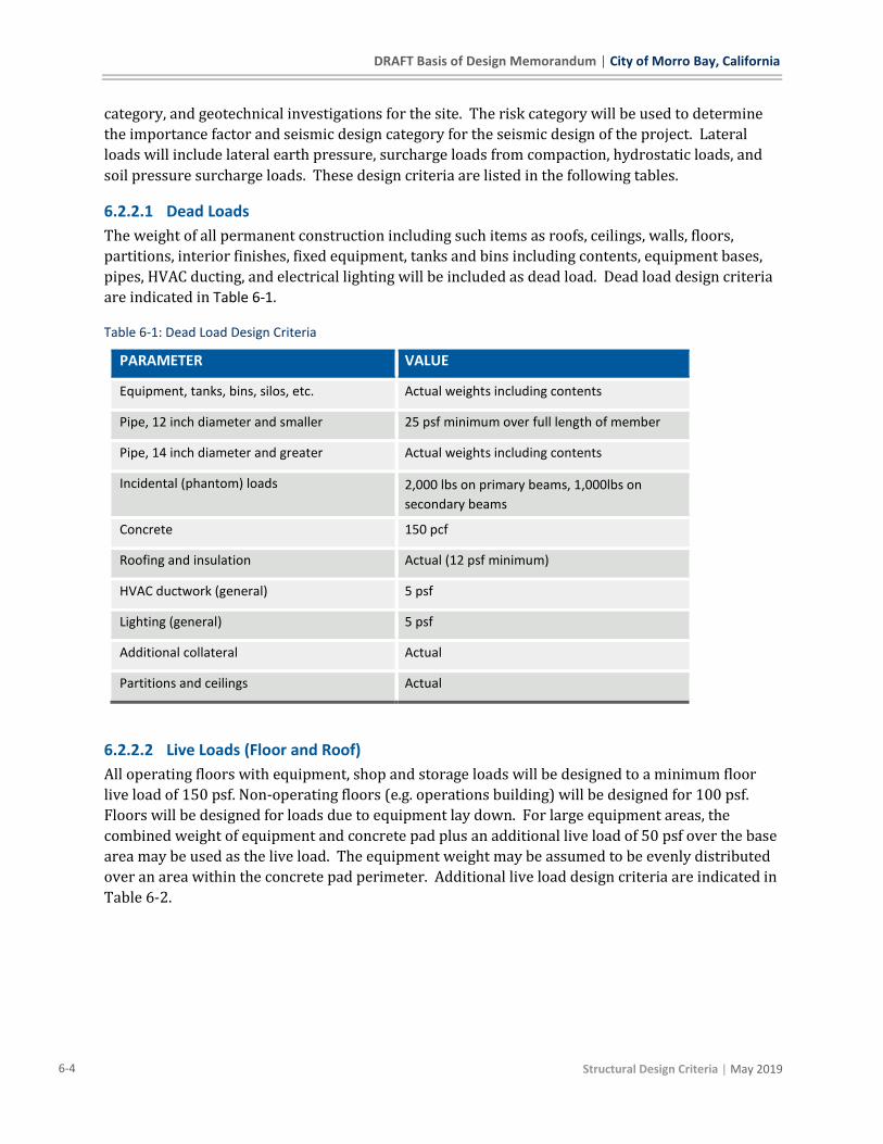
DRAFT Basis of Design Memorandum | City of Morro Bay, California
6-4 Structural Design Criteria | May 2019
category, and geotechnical investigations for the site. The risk category will be used to determine
the importance factor and seismic design category for the seismic design of the project. Lateral
loads will include lateral earth pressure, surcharge loads from compaction, hydrostatic loads, and
soil pressure surcharge loads. These design criteria are listed in the following tables.
6.2.2.1 Dead Loads
The weight of all permanent construction including such items as roofs, ceilings, walls, floors,
partitions, interior finishes, fixed equipment, tanks and bins including contents, equipment bases,
pipes, HVAC ducting, and electrical lighting will be included as dead load. Dead load design criteria
are indicated in Table 6-1.
Table 6-1: Dead Load Design Criteria
PARAMETER VALUE
Equipment, tanks, bins, silos, etc. Actual weights including contents
Pipe, 12 inch diameter and smaller 25 psf minimum over full length of member
Pipe, 14 inch diameter and greater Actual weights including contents
Incidental (phantom) loads 2,000 lbs on primary beams, 1,000lbs on
secondary beams
Concrete 150 pcf
Roofing and insulation Actual (12 psf minimum)
HVAC ductwork (general) 5 psf
Lighting (general) 5 psf
Additional collateral Actual
Partitions and ceilings Actual
6.2.2.2 Live Loads (Floor and Roof)
All operating floors with equipment, shop and storage loads will be designed to a minimum floor
live load of 150 psf. Non-operating floors (e.g. operations building) will be designed for 100 psf.
Floors will be designed for loads due to equipment lay down. For large equipment areas, the
combined weight of equipment and concrete pad plus an additional live load of 50 psf over the base
area may be used as the live load. The equipment weight may be assumed to be evenly distributed
over an area within the concrete pad perimeter. Additional live load design criteria are indicated in
Table 6-2.

City of Morro Bay, California | DRAFT Basis of Design Memorandum
| Structural Design Criteria 6-5
Table 6-2: Live Load Design Criteria
PARAMETER VALUE
Walkways, platforms, stairs 100 psf
Storage, general 250 psf
Control room floors 250 psf
Roof live 20 psf (live load reduction permitted)
Handrails and guards 50 plf, 200 lbs
Intermediate rails 50 lbs
6.2.2.3 Wind Loads
Primary frames that are part of the lateral-force-resisting system along with components and
cladding of structures will be designed for the effects of wind loading in accordance with CBC
Section 1609 and ASCE 7. ASCE7 Chapter 28 (Wind Loads on Buildings – MWFRS) will be used for
low-rise buildings meeting the scope requirements of Section 28.1.1. For other structures, ASCE7
Chapter 29 (Wind Loads on Other Structures and Building Appurtenances – MWFRS) will apply.
Additional wind load design criteria are indicated in Table 6-3.
Table 6-3: Wind Load Design Criteria
PARAMETER VALUE
Risk Category III
Importance Factor 1.0
Basic Wind Speed 115 mph
Exposure Category C
6.2.2.4 Seismic Load
Primary frames that are part of the lateral-force-resisting system along with components of
building structures will have seismic loads determined in accordance with CBC section 1613 and
ASCE7. ASCE 7, Section 12 (Seismic Design Requirements for Building Structures) will provide the
basis for design of buildings and similar structures. Nonbuilding structures will be designed to
ASCE 7, Section 15 (Seismic Design Requirements for Nonbuilding Structures). For liquid
containing (environmental) concrete structures including basins and reservoirs ACI 350.3-06 will
be the basis of design using the response modification factors, R, from ACI 350.3-06, Table 4.1.1(b).
Additional seismic load design criteria are indicated in Table 6-4.
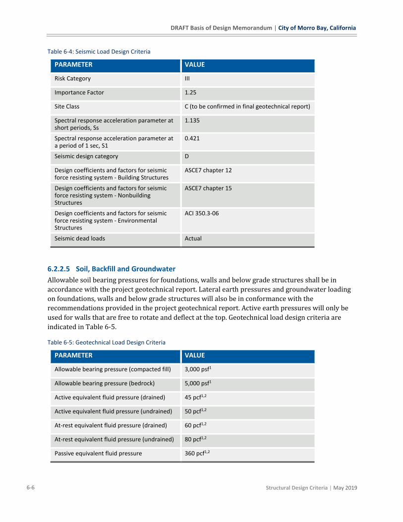
DRAFT Basis of Design Memorandum | City of Morro Bay, California
6-6 Structural Design Criteria | May 2019
Table 6-4: Seismic Load Design Criteria
PARAMETER VALUE
Risk Category III
Importance Factor 1.25
Site Class C (to be confirmed in final geotechnical report)
Spectral response acceleration parameter at short periods, Ss
1.135
Spectral response acceleration parameter at a period of 1 sec, S1
0.421
Seismic design category D
Design coefficients and factors for seismic force resisting system - Building Structures
ASCE7 chapter 12
Design coefficients and factors for seismic force resisting system - Nonbuilding Structures
ASCE7 chapter 15
Design coefficients and factors for seismic force resisting system - Environmental Structures
ACI 350.3-06
Seismic dead loads Actual
6.2.2.5 Soil, Backfill and Groundwater
Allowable soil bearing pressures for foundations, walls and below grade structures shall be in
accordance with the project geotechnical report. Lateral earth pressures and groundwater loading
on foundations, walls and below grade structures will also be in conformance with the
recommendations provided in the project geotechnical report. Active earth pressures will only be
used for walls that are free to rotate and deflect at the top. Geotechnical load design criteria are
indicated in Table 6-5.
Table 6-5: Geotechnical Load Design Criteria
PARAMETER VALUE
Allowable bearing pressure (compacted fill) 3,000 psf1
Allowable bearing pressure (bedrock) 5,000 psf1
Active equivalent fluid pressure (drained) 45 pcf1,2
Active equivalent fluid pressure (undrained) 50 pcf1,2
At-rest equivalent fluid pressure (drained) 60 pcf1,2
At-rest equivalent fluid pressure (undrained) 80 pcf1,2
Passive equivalent fluid pressure 360 pcf1,2
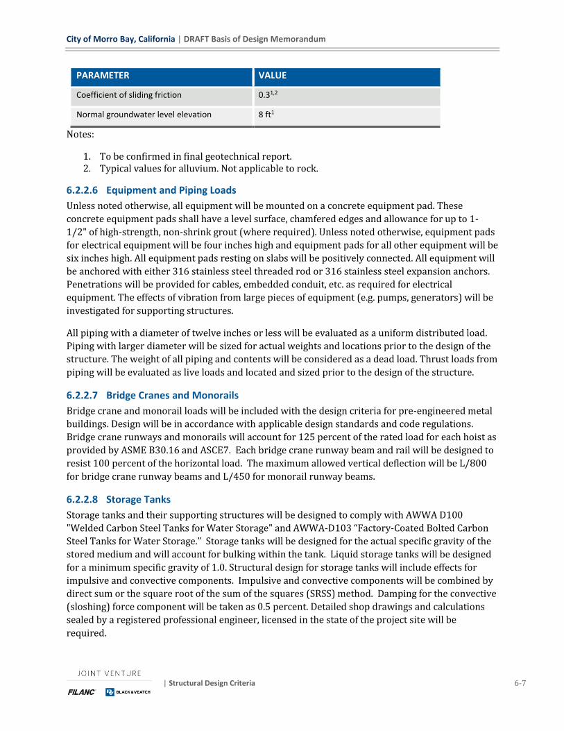
City of Morro Bay, California | DRAFT Basis of Design Memorandum
| Structural Design Criteria 6-7
PARAMETER VALUE
Coefficient of sliding friction 0.31,2
Normal groundwater level elevation 8 ft1
Notes:
1. To be confirmed in final geotechnical report. 2. Typical values for alluvium. Not applicable to rock.
6.2.2.6 Equipment and Piping Loads
Unless noted otherwise, all equipment will be mounted on a concrete equipment pad. These
concrete equipment pads shall have a level surface, chamfered edges and allowance for up to 1-
1/2" of high-strength, non-shrink grout (where required). Unless noted otherwise, equipment pads
for electrical equipment will be four inches high and equipment pads for all other equipment will be
six inches high. All equipment pads resting on slabs will be positively connected. All equipment will
be anchored with either 316 stainless steel threaded rod or 316 stainless steel expansion anchors.
Penetrations will be provided for cables, embedded conduit, etc. as required for electrical
equipment. The effects of vibration from large pieces of equipment (e.g. pumps, generators) will be
investigated for supporting structures.
All piping with a diameter of twelve inches or less will be evaluated as a uniform distributed load.
Piping with larger diameter will be sized for actual weights and locations prior to the design of the
structure. The weight of all piping and contents will be considered as a dead load. Thrust loads from
piping will be evaluated as live loads and located and sized prior to the design of the structure.
6.2.2.7 Bridge Cranes and Monorails
Bridge crane and monorail loads will be included with the design criteria for pre-engineered metal
buildings. Design will be in accordance with applicable design standards and code regulations.
Bridge crane runways and monorails will account for 125 percent of the rated load for each hoist as
provided by ASME B30.16 and ASCE7. Each bridge crane runway beam and rail will be designed to
resist 100 percent of the horizontal load. The maximum allowed vertical deflection will be L/800
for bridge crane runway beams and L/450 for monorail runway beams.
6.2.2.8 Storage Tanks
Storage tanks and their supporting structures will be designed to comply with AWWA D100
"Welded Carbon Steel Tanks for Water Storage" and AWWA-D103 “Factory-Coated Bolted Carbon
Steel Tanks for Water Storage.” Storage tanks will be designed for the actual specific gravity of the
stored medium and will account for bulking within the tank. Liquid storage tanks will be designed
for a minimum specific gravity of 1.0. Structural design for storage tanks will include effects for
impulsive and convective components. Impulsive and convective components will be combined by
direct sum or the square root of the sum of the squares (SRSS) method. Damping for the convective
(sloshing) force component will be taken as 0.5 percent. Detailed shop drawings and calculations
sealed by a registered professional engineer, licensed in the state of the project site will be
required.

DRAFT Basis of Design Memorandum | City of Morro Bay, California
6-8 Structural Design Criteria | May 2019
6.2.2.9 Load Combinations and Allowable Stresses
Building structures, components, and cladding will be designed in accordance with the load
combinations contained in the CBC, Section 1605. Aluminum and cold-formed steel will be designed
using load combinations of CBC, Section 1605.3, and allowable stresses will not be increased unless
specifically allowed per section 1605.3.1.1. Masonry will be designed using the load combinations
in CBC, Section 1605.3. Reinforced concrete for non-environmental structures will be designed
using the load combinations in ACI 318, Section 5.3. Reinforced concrete for environmental
structures will be designed using load combinations in ACI 350, Section 9.2 or Appendix C.
Structural steel will be designed using load combinations of CBC, Section 1605.2.
6.3 DESIGN PROCEDURES AND ASSUMPTIONS
6.3.1 Structural Analysis
Structures will be analyzed for the applicable loads, load combinations and allowable stresses as
required by the governing code and design standards. Structural systems and component forces,
reactions and stresses may be determined using hand calculations or computer programs such as
spreadsheets, RISA-3D, Enercalc, RetainPro, RisaFoundation, etc.
6.3.2 Building Structure Design
Building structures will be designed based upon the criteria established in the CBC and applicable
design standards for loads, load combinations and allowable stresses. Additional concrete design
requirements as specified by ACI 350 will not be considered for building structures unless exposed
to water or aggressive chemicals.
6.3.2.1 Lateral Force Resisting Systems
Lateral loads including wind and seismic forces will be transferred from their origin to the
foundation in a rational manner. Lateral loads will be transferred to vertical and horizontal
resisting elements according to relative rigidity. Accidental torsion, where applicable, will be
considered for seismic design as specified by code and applicable design standards.
6.3.2.2 Horizontal Diaphragms
Diaphragm displacement relative to the supporting vertical lateral force resisting elements will
determine the horizontal distribution of wind and seismic forces. Diaphragm flexibility will be
determined in accordance with ASCE7 section 12.3.1. Where diaphragms meet the requirements for
a flexible diaphragm, lateral load distribution to vertical lateral force resisting elements will be
based on tributary area. Where diaphragms are considered to be rigid, a rigid diaphragm analysis
will be performed to distribute lateral forces based on the relative rigidity of the lateral force
resisting elements.
6.3.2.3 Exterior Walls
Buried exterior walls will be designed to resist the lateral earth pressures specified by the project
geotechnical report. Where roadways are adjacent to buried structure walls, an additional two feet
of soil surcharge will be added to the wall design to account for vehicular live load surcharge.
Additional surcharge loads from compaction equipment during construction will be considered in
design.
City of Morro Bay, California | DRAFT Basis of Design Memorandum
| Structural Design Criteria 6-9
6.3.2.4 Interior Walls
Interior walls will be designed for a minimum 5 psf lateral pressure in accordance with CBC section
1607.14. Interior walls shall be properly anchored to resist these loads and transfer to supporting
elements of the main lateral force resisting system and shall consider roof and floor deflections.
6.3.2.5 Reinforced Concrete Masonry
Reinforced concrete masonry will be designed in accordance with CBC chapter 21 and ACI 530. All
masonry shall be designed as fully grouted with vertical reinforcement spaced no farther than 48
inches on center. Horizontal reinforcement will also be included as required per applicable design
standards.
6.3.2.6 Pre-Engineered Metal Buildings
Pre-engineered metal buildings (PEMB) shall be designed, detailed and fabricated in accordance
with governing design codes and standards by a metal building manufacturer qualified for the
applicable scope of work. PEMB buildings will consist of all steel structures, occupied or not,
located throughout the project site. All metal buildings will be classified as frame-and-purlin
buildings and will be in accordance with the project documents. All frame reaction loads will be
provided by the metal building manufacturer for design of foundations in accordance with the
parameters of the project geotechnical report. Detailed shop drawings and calculations sealed by a
registered professional engineer, licensed in the state of the project site will be required.
6.3.3 Environmental (Liquid-Containing) Structures
6.3.3.1 Scope
This section shall apply to environmental engineering concrete structures as defined in ACI 350 but
does not supersede ASTM standards for precast structures. Generally, environmental structures
shall pertain to structures that will contain process liquids under normal operating conditions.
Structures within the treatment facilities that are exposed to external groundwater pressure or
provided secondary containment for chemicals will also be included.
6.3.3.2 Rectangular Wall Analysis
Environmental structures with rectangular walls will be analyzed as two-way rectangular plates
with appropriately selected boundary conditions where the length to height ratio is 2:1 or less.
Where the length to height ratio exceeds 2:1, the wall will be designed as a one-way rectangular
plate for vertical effects and the corners evaluated for horizontal effect due to boundary conditions
assuming an aspect ratio of 2:1.
6.3.3.3 Axial Tension in Slabs and Walls
Water containment walls shall be designed considering the effects of both flexure and tension in the
wall. Horizontal reinforcement will be distributed for 100% flexure steel and 50% tension steel
(e.g. 50% of tension steel distributed to each face). Direct tension in foundations and top slabs due
to internal water pressure will also be accounted for in the design of horizontal slab reinforcement.
6.3.3.4 Minimum Shrinkage and Temperature Reinforcement
Minimum reinforcement for shrinkage and temperature will be provided in accordance with ACI
350. A minimum reinforcement ratio of 0.005 will be used for walls and base slabs unless

DRAFT Basis of Design Memorandum | City of Morro Bay, California
6-10 Structural Design Criteria | May 2019
reductions are otherwise permitted by ACI 350. Concrete sections of 24 inches or more will have a
minimum reinforcement ratio based on 12 inches at each face. Concrete wall and base slab sections
greater than 10 inches thick will be reinforced with two layers of minimum #5 bars. Concrete wall
and base slab sections 10 inches thick or less will be reinforced with a single layer of minimum #5
bar. Reinforcement in the bottom of base slabs in contact with soil may be reduced to 50 percent of
the required minimum shrinkage and temperature reinforcement listed in Table 7.12.2.1 of ACI
350.
6.3.3.5 Design Load Cases
Basic design load cases will consider the effects of dead load, live load, live roof load and lateral
loads due to hydrostatic loads, lateral earth pressures, seismic, hydrodynamic, dynamic earth
pressure, wind and groundwater pressures. Soil pressure will include at-rest or active pressures,
surcharge and seismic effects. A maximum service water level will be considered for the design of
all liquid containing structures along with soil with normal groundwater, maximum overflow water,
seismic water, flooded soil and seismic soil conditions.
6.3.3.6 Load Case: Service Water Level
The service level water condition will assume adjacent chambers or basins as empty and ignore the
counteractive effects of soil backfill loads. Service level water condition is the maximum water level
during normal operations. This condition will also consider direct tension in the walls due to the
service water level. Durability factors as defined in ACI 350 apply to this condition.
6.3.3.7 Load Case: Soil with Normal Groundwater Elevation
This condition assumes the maximum soil backfill pressures, including surcharges, with the
groundwater at normal elevations. The tanks or basins will be assumed to be without liquid and
ignores any counteractive effects due to internal liquid loads. Surcharge vehicle loading will be
considered by increasing the soil surcharge height by two feet. Durability factors as defined in ACI
350 apply to this condition.
6.3.3.8 Load Case: Maximum Water Condition
The maximum level water condition is the temporary maximum internal water level. This level will
be considered the greater of the tightness testing water elevation and the maximum water level
that is possible hydraulically. Counteractive effects of soil backfill loads will be ignored. This
condition will also consider direct tension in the walls due to the maximum water level. ACI 350
durability factors do not apply to this condition.
6.3.3.9 Load Case: Saturated Soil Condition
This condition will consider maximum backfill conditions with groundwater at the 100 year flood
elevation in combination with adjacent design truck surcharge. The tank will be considered to be
empty and any counteractive effects of internal water pressure will be neglected. ACI 350 durability
factors do not apply to this condition.
6.3.3.10 Load Case: Seismic Water Condition
Seismic water condition will evaluate the hydrodynamic forces in the internal water at its
maximum service level due to earthquake ground motions. The hydrodynamic forces evaluated will
include convective and sloshing forces in accordance with the referenced design standards.
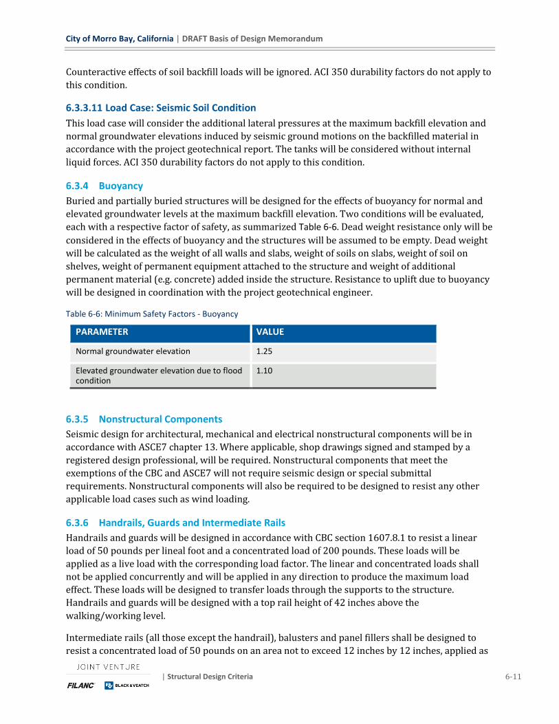
City of Morro Bay, California | DRAFT Basis of Design Memorandum
| Structural Design Criteria 6-11
Counteractive effects of soil backfill loads will be ignored. ACI 350 durability factors do not apply to
this condition.
6.3.3.11 Load Case: Seismic Soil Condition
This load case will consider the additional lateral pressures at the maximum backfill elevation and
normal groundwater elevations induced by seismic ground motions on the backfilled material in
accordance with the project geotechnical report. The tanks will be considered without internal
liquid forces. ACI 350 durability factors do not apply to this condition.
6.3.4 Buoyancy
Buried and partially buried structures will be designed for the effects of buoyancy for normal and
elevated groundwater levels at the maximum backfill elevation. Two conditions will be evaluated,
each with a respective factor of safety, as summarized Table 6-6. Dead weight resistance only will be
considered in the effects of buoyancy and the structures will be assumed to be empty. Dead weight
will be calculated as the weight of all walls and slabs, weight of soils on slabs, weight of soil on
shelves, weight of permanent equipment attached to the structure and weight of additional
permanent material (e.g. concrete) added inside the structure. Resistance to uplift due to buoyancy
will be designed in coordination with the project geotechnical engineer.
Table 6-6: Minimum Safety Factors - Buoyancy
PARAMETER VALUE
Normal groundwater elevation 1.25
Elevated groundwater elevation due to flood condition
1.10
6.3.5 Nonstructural Components
Seismic design for architectural, mechanical and electrical nonstructural components will be in
accordance with ASCE7 chapter 13. Where applicable, shop drawings signed and stamped by a
registered design professional, will be required. Nonstructural components that meet the
exemptions of the CBC and ASCE7 will not require seismic design or special submittal
requirements. Nonstructural components will also be required to be designed to resist any other
applicable load cases such as wind loading.
6.3.6 Handrails, Guards and Intermediate Rails
Handrails and guards will be designed in accordance with CBC section 1607.8.1 to resist a linear
load of 50 pounds per lineal foot and a concentrated load of 200 pounds. These loads will be
applied as a live load with the corresponding load factor. The linear and concentrated loads shall
not be applied concurrently and will be applied in any direction to produce the maximum load
effect. These loads will be designed to transfer loads through the supports to the structure.
Handrails and guards will be designed with a top rail height of 42 inches above the
walking/working level.
Intermediate rails (all those except the handrail), balusters and panel fillers shall be designed to
resist a concentrated load of 50 pounds on an area not to exceed 12 inches by 12 inches, applied as
DRAFT Basis of Design Memorandum | City of Morro Bay, California
6-12 Structural Design Criteria | May 2019
a live load. This concentrated load need not be applied simultaneously with handrail and guard
loads.
6.3.7 Site Retaining Walls
Site retaining walls will be designed in accordance with the requirements and design values
provided in the project geotechnical report. Site walls will be designed as unrestrained at the top
with the active earth pressure applied at the maximum anticipated backfill elevation. If detailed
with proper restraint at the top of the wall, the at-rest earth pressure will be used. An additional
two feet of backfill material will be applied to the design of retaining walls to account for adjacent
roadway surcharges where applicable.
To the extent possible, segmental block retaining walls (such as Versa-Lok) will be utilized. Below 3
feet tall, no structural design is required. Above 3 feet tall will be engineered per segmental block
retaining wall manufacturer requirements.
6.4 SPECIAL INSPECTION AND STRUCTURAL OBSERVATION Special inspections and structural observations will be required in accordance with the
requirements of CBC chapter 17. These inspections and observations will be included with the
project documents. The requirements listed on the project documents does not waive the right of
the governing jurisdiction to require testing and inspection of any material at any time.

City of Morro Bay, California | DRAFT Basis of Design Memorandum
| Architectural Design Criteria 7-1
7 Architectural Design Criteria
7.1 GENERAL WRF building layouts, proportions, systems and materials are chosen to meet the City of Morro
Bay's programmatic requirements, life-cycle cost effectiveness criteria, and compliance with the
regulatory constraints described below. Additional design considerations are durability,
compatibility with the marine environment, low maintenance, energy conservation and related
sustainable features.
Walls, roof forms, exterior colors schemes, and landscape screening are designed to meet the City's
desire for an appearance from the Highway 1 scenic corridor that is recognizably agricultural,
giving the overall impression typical of a dairy farm or ranch.
7.2 BUILDING CODES
7.2.1 Building Codes and Applicable Laws
The architectural design and construction of the WRF facilities will comply, at a minimum, with
these building codes and applicable laws:
◼ 2016 California Building Code - (CBC) 2016 - Title 24, Part 2 of the California Code of Regulations
(CCR), incorporating by adoption the 2015 International Building Code (IBC) with California
Amendments.
◼ 2016 California Electrical Code - (CEC) 2016 - Title 24, Part 3 of the California Code of
Regulations (CCR), incorporating by adoption the 2014 National Electric Code (NEC) with
California Amendments.
◼ 2016 California Mechanical Code - (CMC) 2016 - Title 24, Part 4 of the California Code of
Regulations (CCR), incorporating by adoption the 2015 Uniform Mechanical Code (UMC) with
California Amendments.
◼ 2016 California Plumbing Code - (CBC) 2016 - Title 24, Part 5 of the California Code of
Regulations (CCR), incorporating by adoption the 2015 Uniform Plumbing Code (UPC) with
California Amendments.
◼ 2016 California Fire Code - (CFC) 2016 - Title 24, Part 9 of the California Code of Regulations
(CCR), incorporating by adoption the 2015 International Fire Code (IFC) with California
Amendments.
◼ 2016 California Green Building Standards - (CALGreen) 2016 - Title 24, Part 11 of the California
Code of Regulations (CCR).
◼ 2015 California Division of Occupational Safety and Health - (Cal/OSHA) 2015 - Title 8 of the
California Code of Regulations (CCR), with applicable component updates.
◼ California Coastal Zone Management Act, applicable provisions.
DRAFT Basis of Design Memorandum | City of Morro Bay, California
7-2 Architectural Design Criteria | May 2019
7.2.2 Accessibility Recommendations
The process areas of the WRF are generally considered exempt from the accessi bility
requirements of CBC Chapter 11B. The design is based on the following recommended
application of accessibility standards:
◼ Building entrances and interiors of Operations Building and Maintenance Building
◼ Building entrances only at RO/UV Building and Electrical Building
◼ Parking and Exterior Path-Of-Travel at Operations Building and Maintenance Building
7.2.3 Additional Standards
In addition to the applicable codes and standards previously identified, the system designs will also
be based on, but not limited to, the following reference standards described in the project's
specifications:
◼ Underwriters Laboratories (UL)
◼ Builders Hardware Manufacturers Associations (BHMA)
◼ American Society for Testing and Materials International (ASTM)
◼ American National Standards Institute (ANSI)
◼ Factory Mutual (FM)
◼ American Wood Protection Association (AWPA)
◼ American Concrete Institute (ACI)
◼ American Institute of Steel Construction (AISC)
◼ The Aluminum Association
7.3 BUILDING DESCRIPTIONS
7.3.1 OPERATIONS BUILDING
7.3.1.1 Description
The Operations Building contains functions that can all be defined as "office," serving as the
administrative hub for the facility. The floor plan locates visitor spaces (Lobby, Conference Room,
and Break Room) adjacent to the visitor entry on the east side of the building. Staff functions are
accessed from staff parking on the north side. The control room is open access without doors per
City request and placed centrally in the staff function spaces, along with the three primary offices,
on the northeast wall for daylighting. The break and training room is placed on the south side of the
building which opens to a staff patio, allowing passive solar heating of these spaces. Visitor access
is via controlled entry to the building. Once inside, there are no physical access restrictions which
limit visitor access to the Control Room and most spaces with exception of locked offices and
rooms.
The building was laid in out per City input to facilitate direct access from the staff parking lot to the
City of Morro Bay, California | DRAFT Basis of Design Memorandum
| Architectural Design Criteria 7-3
Laundry/Uniform and Locker Rooms. Men's and Women's Locker Rooms are furnished with
ganged shower stalls. A single unisex bathroom is furnished but no unisex shower is furnished per
City request to focus expenditure on providing the greatest number of showers possible in the
Men's and Women's Locker Rooms. Plumbing fixture counts substantially exceed minimum code
requirements.
7.3.1.2 Code Compliance
Occupancy Classification: B (Office)
Construction Type: Type VB
Floor Area: 5,550 s.f. (36,000 allowed)
Minimum Setback: approx. 87 feet (east property line)
Exterior Wall Fire Resistance: none required
Fire Sprinklers: NFPA 13 wet system throughout
Title 24 Compliance: all conditioned spaces
7.3.1.3 Exterior Walls
The exterior building walls are a combination of metal siding and concrete masonry over insulated,
wood or metal stud framed cavity walls. A concrete masonry base rises to +48 inches and all
exposed-to-view units are pigmented, with a split-face or burnished surface. The masonry portion
of the wall is structural only where it provides retaining. Upper wall surfaces are a combination of
two profiles of metal siding, with "Zincalume" treatment and fluoropolymer coating. Trims and
transitions are standard products available from the selected pre-engineered building
manufacturer.
7.3.1.4 Roofs
All roofs are ribbed metal structural or non-structural panels with a standing-batten appearance,
with "Zincalume" treatment and fluoropolymer coating. Exposed fasteners, gutters, downspouts,
penetrations, and transitions are standard products of the pre-engineered building manufacturer to
the extent possible.
7.3.1.5 Interior Walls, Finishes
The interior building walls are non-bearing wood or metal stud walls, sound insulated at all
occupied spaces, and finished with painted, light orange peel textured gypsum board. Ceilings in
utility spaces are painted gypsum board; other ceilings are suspended acoustic tile. Floors are
polished and sealed concrete. Moisture-exposed walls and floors in showers and restrooms will be
finished with porcelain or glazed ceramic tile.
7.3.1.6 Openings
Exterior utility doors are fiberglass in painted, galvanized steel frames. Other exterior doors,
sidelights and windows are an aluminum storefront system with a fluoropolymer frame finish and
high performance glazing. Interior doors are painted, galvanized steel in galvanized steel frames.

DRAFT Basis of Design Memorandum | City of Morro Bay, California
7-4 Architectural Design Criteria | May 2019
7.3.2 MAINTENANCE BUILDING
7.3.2.1 Description
The Maintenance Building combines open vehicle maintenance and shop space with enclosed
restroom, I&C workshop, control, and laboratory spaces that can be defined as "accessory,"
assuming they do not involve storage or operations considered hazardous. An exterior opening
paint and oil storage room is furnished to provide space for these materials per City request
without impacting the code classification of the entire building. The floor plan is arranged to
accommodate vehicle drive-through oriented to site circulation. The enclosed functions are placed
at a 3.75 foot higher elevation in response to site topography. The vehicle and shop space is laid out
to provide a clear path for a bridge crane.
7.3.2.2 Code Compliance
Occupancy Classification: F-2 (Low Hazard Factory Industrial)
Construction Type: Type IIB
Floor Area: 5,400 s.f. (92,000 allowed)
Minimum Setback: approx. 30 feet (Chemical Area)
Exterior Wall Fire Resistance: none required
Fire Sprinklers: NFPA 13 wet system throughout
Title 24 Compliance: conditioned I&C workshop, control, and laboratory space
7.3.2.3 Exterior Walls
The exterior building walls are a combination of metal siding and concrete masonry. At the
restroom, workshop, control, and laboratory spaces exterior finishes are over insulated, metal stud
framed cavity walls. Maintenance space exterior finishes are exposed at the interior. The concrete
masonry base rises to +48 inches and all exposed-to-view units are pigmented, with a split-face or
burnished surface, and provides structural retaining at grade changes. Upper wall surfaces are a
ribbed profile of metal siding, with "Zincalume" treatment and fluoropolymer coating, and
manufacturer's standard trims and transitions.
7.3.2.4 Roofs
The roof is made of ribbed metal structural or non-structural panels with a standing-batten
appearance, "Zincalume" treated and fluoropolymer coated. Exposed fasteners, gutters,
downspouts, penetrations, and transitions are standard manufacturer's products.
7.3.2.5 Interior Walls, Finishes
Interior walls are non-bearing metal stud walls, sound insulated and finished with painted, light
orange peel textured gypsum board. The wall and ceiling structure is exposed in the open shop
space. Ceilings in enclosed spaces are painted gypsum board. Floors are polished and sealed
concrete. Moisture-exposed restroom walls will be finished with porcelain or glazed ceramic tile.

City of Morro Bay, California | DRAFT Basis of Design Memorandum
| Architectural Design Criteria 7-5
7.3.2.6 Openings
Exterior utility doors are fiberglass in painted, galvanized steel frames. Overhead sectional doors
are motorized with manual override, constructed of prefinished aluminum slats. Windows are
prefinished aluminum. Interior doors are painted, galvanized steel in galvanized steel frames.
7.3.3 RO/UV BUILDING
7.3.3.1 Description
The RO/UV Building is made up of open process space and an enclosed electrical room. Building
openings are arranged to accommodate equipment access from the exterior. The facility includes a
weather protected exterior containment pad.
7.3.3.2 Code Compliance
Occupancy Classification: F-2 (Low Hazard Factory Industrial)
Construction Type: Type IIB
Floor Area: 3,960 s.f. (23,000 allowed)
Minimum Setback: approx. 20 feet (Calcite Contactors Area)
Exterior Wall Fire Resistance: none required
Fire Sprinklers: no
Title 24 Compliance: no (non-conditioned)
7.3.3.3 Exterior Walls
The exterior building walls are a combination of metal siding and concrete masonry. In the open
equipment area, exterior finishes are exposed at the interior. At the enclosed electrical room,
exterior finishes are over insulated, metal stud framed cavity walls The concrete masonry base
rises to +48 inches and all exposed-to-view units are pigmented, with a split-face or burnished
surface. Upper wall surfaces are a ribbed profile of metal siding, with "Zincalume" treatment and
fluoropolymer coating, and manufacturer's standard trims and transitions.
7.3.3.4 Roofs
The roof is made of ribbed metal structural or non-structural panels with a standing-batten
appearance, "Zincalume" treated and fluoropolymer coated. Exposed fasteners, gutters,
downspouts, penetrations, and transitions are standard manufacturer's products.
7.3.3.5 Interior Walls, Finishes
Interior walls are framed with non-bearing metal studs, finished with painted, light orange peel
textured gypsum board. The wall and ceiling structure is exposed in the open shop space; the
ceiling in the electrical room is painted gypsum board. Floors are polished and sealed concrete.
DRAFT Basis of Design Memorandum | City of Morro Bay, California
7-6 Architectural Design Criteria | May 2019
7.3.3.6 Openings
Exterior utility doors are fiberglass in painted, galvanized steel frames. The overhead sectional door
is motorized with manual override, constructed of prefinished aluminum slats. Windows are
prefinished aluminum. The interior door is painted, galvanized steel in a galvanized steel frame.
7.3.4 MISCELLANEOUS STRUCTURES AND CANOPIES
7.3.4.1 Description
The WRF list of structures contains additional pre-engineered metal buildings and weather
protective covers, including the dewatering canopy, chemical facility canopy, collection supply
storage, water supply storage, covered parking and covered storage slabs.
7.3.4.2 Code Compliance
Occupancy Classification: F-2 (Low Hazard Factory Industrial) or H-4 (High Hazard),
depending on chemical storage
Construction Type: Type IIB
Floor Area: varies
Minimum Setback: varies, 10 feet minimum
Exterior Wall Fire Resistance: none required
Fire Sprinklers: no
Title 24 Compliance: no (non-conditioned)
7.3.4.3 Exterior Walls
Canopies and miscellaneous weather protective covers are open at the exterior, with exposed,
primed and painted steel vertical structure. Exterior walls at enclosed miscellaneous structures are
a ribbed profile of metal siding, with "Zincalume" treatment and fluoropolymer coating, and
manufacturer's standard trims and transitions.
7.3.4.4 Roofs
Roofs are made of ribbed metal structural or non-structural panels with a standing-batten
appearance, "Zincalume" treated and fluoropolymer coated. Exposed fasteners, gutters,
downspouts, penetrations, and transitions are standard manufacturer's products.
7.3.4.5 Interior Walls, Finishes
Miscellaneous enclosed structure have exposed wall and roof panels at the interior. Floors are
polished and sealed concrete.
7.3.4.6 Openings
Exterior utility doors are fiberglass, in painted, galvanized steel frames. Windows are prefinished
aluminum.

City of Morro Bay, California | DRAFT Basis of Design Memorandum
| Building Mechanical and Fire Design Criteria 8-1
8 Building Mechanical and Fire Design Criteria
8.1 GENERAL This section presents the criteria and basis of mechanical design associated with the plumbing,
heating, ventilating, and air conditioning (HVAC) and fire protection systems. The intent of this
section is to define the design criterion, establish the minimum design requirements, and describe
the mechanical systems. The selection of the systems will be based on operating performance,
system efficiency, life safety considerations, long-term durability, redundancy, local
representation/service, ease of operation as well as site and specific requirements identified by the
project team or Owner as described herein.
8.2 APPLICABLE CODES AND STANDARDS In addition to the applicable codes and standards previously identified, the system design will also
be based on but not limited to the following building codes and standards.
◼ 2016 California Building Code (2015 International Building Code with California Amendments)
◼ 2016 California Mechanical Code (2015 Uniform Mechanical Code with California Amendments)
◼ 2016 California Plumbing Code (2015 Uniform Plumbing Code with California Amendments)
◼ 2016 CFC (2015 International Fire Code with California Amendments)
◼ 2016 California Energy Code.
◼ 2016 California Green Building Standards Code.
◼ California Title 24 Building Energy Efficiency Standards
◼ American Society of Plumbing Engineers (ASPE) Handbooks.
◼ American Society of Heating, Refrigeration, and Air Conditioning Engineers (ASHRAE)
Handbooks and Standards.
◼ Sheet Metal and Air Conditioning Contractor National Association (SMACNA) handbooks.
◼ National Fire Protection Association Recommended Practices (NFPA) and Manuals.
◼ Recommended Standards for Sewage Works - Great Lakes - Upper Mississippi River Board of
Sanitary Engineers (10 States Standards).
◼ Occupational Safety and Health Act (OSHA) Standards Manual.
In addition to the applicable codes and standards previously identified, the system designs
will also be based on but not limited to the following publications and standards:
◼ Underwriter Laboratories (UL)
◼ American Society for Testing and Materials International (ASTM)
◼ Aluminum Association (AA); Aluminum Sheet Metal Work in Construction
◼ National Fire Protection Agency (NFPA) recommended practices and manuals
◼ Life Safety Code – National Fire Protection Agency (NFPA)
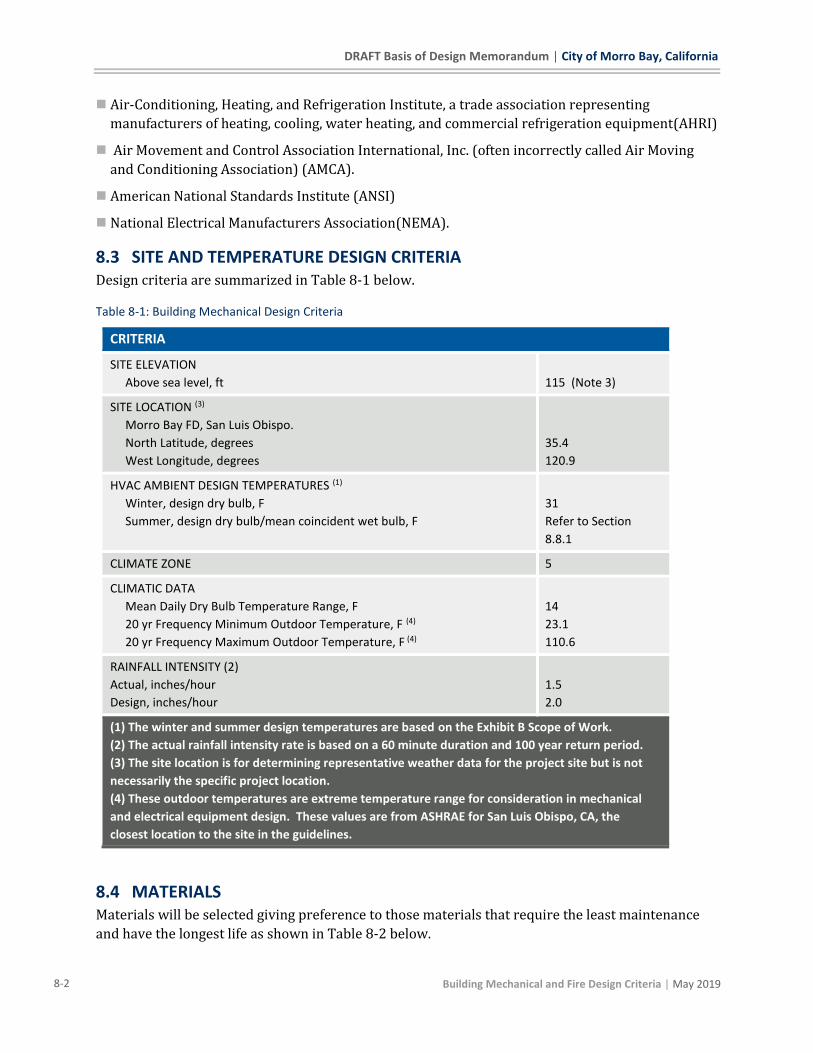
DRAFT Basis of Design Memorandum | City of Morro Bay, California
8-2 Building Mechanical and Fire Design Criteria | May 2019
◼ Air-Conditioning, Heating, and Refrigeration Institute, a trade association representing
manufacturers of heating, cooling, water heating, and commercial refrigeration equipment(AHRI)
◼ Air Movement and Control Association International, Inc. (often incorrectly called Air Moving
and Conditioning Association) (AMCA).
◼ American National Standards Institute (ANSI)
◼ National Electrical Manufacturers Association(NEMA).
8.3 SITE AND TEMPERATURE DESIGN CRITERIA Design criteria are summarized in Table 8-1 below.
Table 8-1: Building Mechanical Design Criteria
CRITERIA
SITE ELEVATION
Above sea level, ft
115 (Note 3)
SITE LOCATION (3)
Morro Bay FD, San Luis Obispo.
North Latitude, degrees
West Longitude, degrees
35.4
120.9
HVAC AMBIENT DESIGN TEMPERATURES (1)
Winter, design dry bulb, F
Summer, design dry bulb/mean coincident wet bulb, F
31
Refer to Section
8.8.1
CLIMATE ZONE 5
CLIMATIC DATA
Mean Daily Dry Bulb Temperature Range, F
20 yr Frequency Minimum Outdoor Temperature, F (4)
20 yr Frequency Maximum Outdoor Temperature, F (4)
14
23.1
110.6
RAINFALL INTENSITY (2)
Actual, inches/hour
Design, inches/hour
1.5
2.0
(1) The winter and summer design temperatures are based on the Exhibit B Scope of Work.
(2) The actual rainfall intensity rate is based on a 60 minute duration and 100 year return period.
(3) The site location is for determining representative weather data for the project site but is not
necessarily the specific project location.
(4) These outdoor temperatures are extreme temperature range for consideration in mechanical
and electrical equipment design. These values are from ASHRAE for San Luis Obispo, CA, the
closest location to the site in the guidelines.
8.4 MATERIALS Materials will be selected giving preference to those materials that require the least maintenance
and have the longest life as shown in Table 8-2 below.
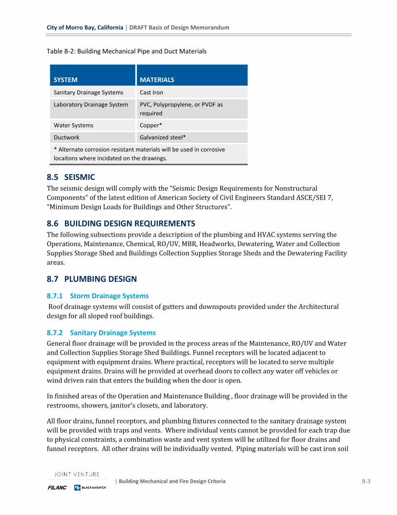
City of Morro Bay, California | DRAFT Basis of Design Memorandum
| Building Mechanical and Fire Design Criteria 8-3
Table 8-2: Building Mechanical Pipe and Duct Materials
SYSTEM
MATERIALS
Sanitary Drainage Systems Cast Iron
Laboratory Drainage System PVC, Polypropylene, or PVDF as
required
Water Systems Copper*
Ductwork Galvanized steel*
* Alternate corrosion resistant materials will be used in corrosive
locaitons where incidated on the drawings.
8.5 SEISMIC The seismic design will comply with the “Seismic Design Requirements for Nonstructural
Components” of the latest edition of American Society of Civil Engineers Standard ASCE/SEI 7,
“Minimum Design Loads for Buildings and Other Structures”.
8.6 BUILDING DESIGN REQUIREMENTS The following subsections provide a description of the plumbing and HVAC systems serving the
Operations, Maintenance, Chemical, RO/UV, MBR, Headworks, Dewatering, Water and Collection
Supplies Storage Shed and Buildings Collection Supplies Storage Sheds and the Dewatering Facility
areas.
8.7 PLUMBING DESIGN
8.7.1 Storm Drainage Systems
Roof drainage systems will consist of gutters and downspouts provided under the Architectural
design for all sloped roof buildings.
8.7.2 Sanitary Drainage Systems
General floor drainage will be provided in the process areas of the Maintenance, RO/UV and Water
and Collection Supplies Storage Shed Buildings. Funnel receptors will be located adjacent to
equipment with equipment drains. Where practical, receptors will be located to serve multiple
equipment drains. Drains will be provided at overhead doors to collect any water off vehicles or
wind driven rain that enters the building when the door is open.
In finished areas of the Operation and Maintenance Building , floor drainage will be provided in the
restrooms, showers, janitor’s closets, and laboratory.
All floor drains, funnel receptors, and plumbing fixtures connected to the sanitary drainage system
will be provided with traps and vents. Where individual vents cannot be provided for each trap due
to physical constraints, a combination waste and vent system will be utilized for floor drains and
funnel receptors. All other drains will be individually vented. Piping materials will be cast iron soil
DRAFT Basis of Design Memorandum | City of Morro Bay, California
8-4 Building Mechanical and Fire Design Criteria | May 2019
pipe with hubless or bell and spigot joints for above grade locations and bell and spigot joints for
below grade locations.
All plumbing fixtures and floor drains located on the floor at or above grade will discharge by
gravity to the plant sanitary sewer.
The floor drains, sinks, and equipment drains located in the laboratory area will discharge into a
neutralization tank if required. The neutralization tank will be below grade and discharge to the
sanitary system. All drainage and vent piping and accessories associated with the laboratory waste
system will be constructed of chemical resistant materials.
All plumbing fixtures and floor drains located at the WRF will discharge by gravity to a lift station
on site, which will discharge to the WRF sanitary sewer system.
In the Chemical Facility, permanent air diaphragm sump pumps will be designed by process
mechanical.
In the Dewatering Area and Maintenance Building, floor drainage will be provided in the
Dewatering Area, Mechanical and Laboratory Rooms. Plumbing fixtures and floor drainage will be
drained directly to the sanitary drainage system.
In the RO/UV and Maintenance Buildings, trench drains will be provided in the RO room and
Service Truck bay. Plumbing fixtures and floor drains will be drained directly to the sanitary
drainage system.
8.7.3 Water Piping System
Potable hot, cold and tempered water will be supplied to the domestic water fixtures and
emergency shower/eyewash fixtures. The anticipated water pressure is approximately 70 psig;
therefore, water pressure boosting equipment will not be required. A central water meter will be
provided at the site water service entrance. Piping materials will consist of soft annealed copper
tubing with flared fittings for buried sizes 2 inch and smaller and type K hard drawn copper tubing
with solder joint fittings for above grade piping.
All materials in contact with the potable water will comply with the Safe Drinking Water Act of
1986 as amended by the Reduction of Lead in Drinking Water Act of 2011. All plumbing fittings and
fixtures intended to convey or dispense water for human consumption will comply with the
requirements of NSF/ANSI 61 and NSF/ANSI 372 for low lead.
Domestic hot and cold water will be provided to plumbing fixtures as required. A water heater and
blending valve will be provided in the cold water supply to the emergency shower/eyewash
fixtures to permit tepid water temperatures (60°F to 90°F) to be supplied to the fixtures. Hot water
recirculation system will be provided for fixtures over 50 feet from the water heater. In chemical
facility instantaneous electric water heater will be provided to supply tepid water to emergency
fixtures.
¾ inch hose faucets and 1-1/2 inch hose valves will be provided in unfinished areas including the
Truck Service Bay, Headworks ,MBR, and Dewatering Area.
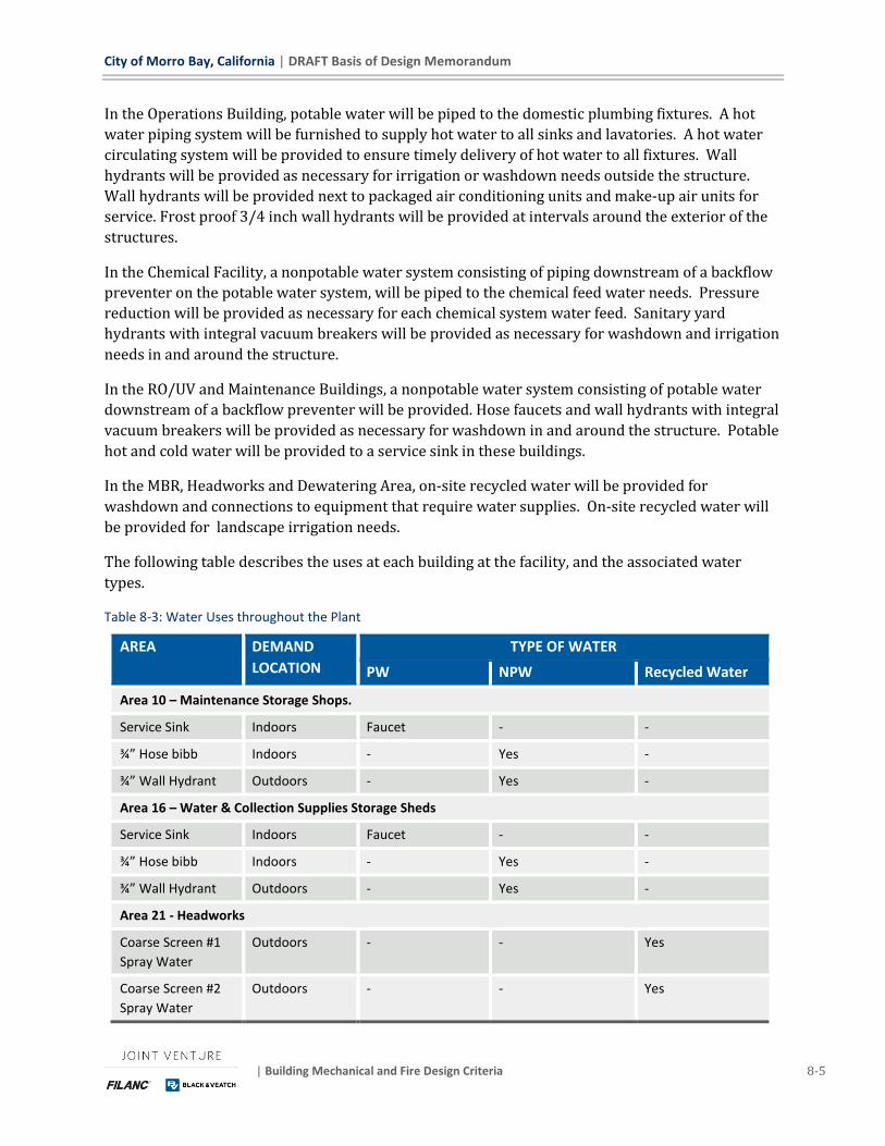
City of Morro Bay, California | DRAFT Basis of Design Memorandum
| Building Mechanical and Fire Design Criteria 8-5
In the Operations Building, potable water will be piped to the domestic plumbing fixtures. A hot
water piping system will be furnished to supply hot water to all sinks and lavatories. A hot water
circulating system will be provided to ensure timely delivery of hot water to all fixtures. Wall
hydrants will be provided as necessary for irrigation or washdown needs outside the structure.
Wall hydrants will be provided next to packaged air conditioning units and make-up air units for
service. Frost proof 3/4 inch wall hydrants will be provided at intervals around the exterior of the
structures.
In the Chemical Facility, a nonpotable water system consisting of piping downstream of a backflow
preventer on the potable water system, will be piped to the chemical feed water needs. Pressure
reduction will be provided as necessary for each chemical system water feed. Sanitary yard
hydrants with integral vacuum breakers will be provided as necessary for washdown and irrigation
needs in and around the structure.
In the RO/UV and Maintenance Buildings, a nonpotable water system consisting of potable water
downstream of a backflow preventer will be provided. Hose faucets and wall hydrants with integral
vacuum breakers will be provided as necessary for washdown in and around the structure. Potable
hot and cold water will be provided to a service sink in these buildings.
In the MBR, Headworks and Dewatering Area, on-site recycled water will be provided for
washdown and connections to equipment that require water supplies. On-site recycled water will
be provided for landscape irrigation needs.
The following table describes the uses at each building at the facility, and the associated water
types.
Table 8-3: Water Uses throughout the Plant
AREA DEMAND
LOCATION
TYPE OF WATER
PW NPW Recycled Water
Area 10 – Maintenance Storage Shops.
Service Sink Indoors Faucet - -
¾” Hose bibb Indoors - Yes -
¾” Wall Hydrant Outdoors - Yes -
Area 16 – Water & Collection Supplies Storage Sheds
Service Sink Indoors Faucet - -
¾” Hose bibb Indoors - Yes -
¾” Wall Hydrant Outdoors - Yes -
Area 21 - Headworks
Coarse Screen #1
Spray Water
Outdoors - - Yes
Coarse Screen #2
Spray Water
Outdoors - - Yes

DRAFT Basis of Design Memorandum | City of Morro Bay, California
8-6 Building Mechanical and Fire Design Criteria | May 2019
AREA DEMAND
LOCATION
TYPE OF WATER
PW NPW Recycled Water
Grit Pump #1 Seal
Water
Outdoors - - Yes
Grit Pump #2 Seal
Water
Outdoors - - Yes
¾” Yard Hydrant Outdoors - - Yes
1” Yard Hydrant Outdoors - - Yes
Area 22 – Fine Screens
Fine Screen #1
Spray Water
Outdoors - - Yes
Fine Screen #2
Spray Water
Outdoors - - Yes
¾” Yard Hydrant Outdoors - - Yes
1” Yard Hydrant Outdoors - - Yes
Area 24 – Vactor Washdown
¾” Yard Hydrant Outdoors - - Yes
1” Yard Hydrant Outdoors - - Yes
Area 31 - BNR
Scum Spray Outdoors - - Yes
1” Yard Hydrant Outdoors - - Yes
¾” Hose bibb Outdoors - - Yes
Area 32 - MBR
1” Yard Hydrant Outdoors - - Yes
¾” Hose bibb Outdoors - - Yes
Area 50 – RO/UV
1-½” Hose valves Indoors - Yes -
¾” Hose bibb Indoors - Yes -
Emergency Shower
and Eyewash(CIP
Tank Area)
Indoors Yes - -
Exterior wall
hydrants
Outdoors - Yes -
Area 60 – Product Water
Calcite Contactors
Area
Outdoors - Yes -
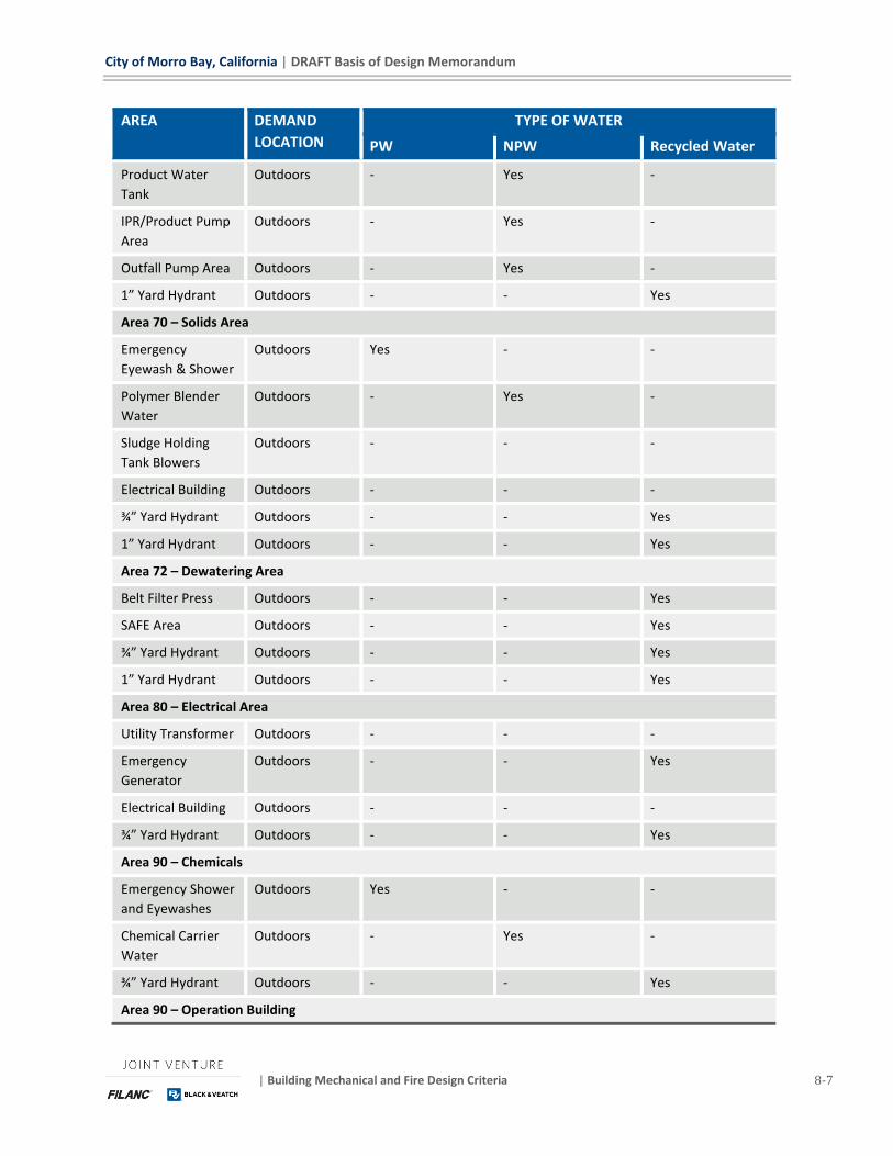
City of Morro Bay, California | DRAFT Basis of Design Memorandum
| Building Mechanical and Fire Design Criteria 8-7
AREA DEMAND
LOCATION
TYPE OF WATER
PW NPW Recycled Water
Product Water
Tank
Outdoors - Yes -
IPR/Product Pump
Area
Outdoors - Yes -
Outfall Pump Area Outdoors - Yes -
1” Yard Hydrant Outdoors - - Yes
Area 70 – Solids Area
Emergency
Eyewash & Shower
Outdoors Yes - -
Polymer Blender
Water
Outdoors - Yes -
Sludge Holding
Tank Blowers
Outdoors - - -
Electrical Building Outdoors - - -
¾” Yard Hydrant Outdoors - - Yes
1” Yard Hydrant Outdoors - - Yes
Area 72 – Dewatering Area
Belt Filter Press Outdoors - - Yes
SAFE Area Outdoors - - Yes
¾” Yard Hydrant Outdoors - - Yes
1” Yard Hydrant Outdoors - - Yes
Area 80 – Electrical Area
Utility Transformer Outdoors - - -
Emergency
Generator
Outdoors - - Yes
Electrical Building Outdoors - - -
¾” Yard Hydrant Outdoors - - Yes
Area 90 – Chemicals
Emergency Shower
and Eyewashes
Outdoors Yes - -
Chemical Carrier
Water
Outdoors - Yes -
¾” Yard Hydrant Outdoors - - Yes
Area 90 – Operation Building
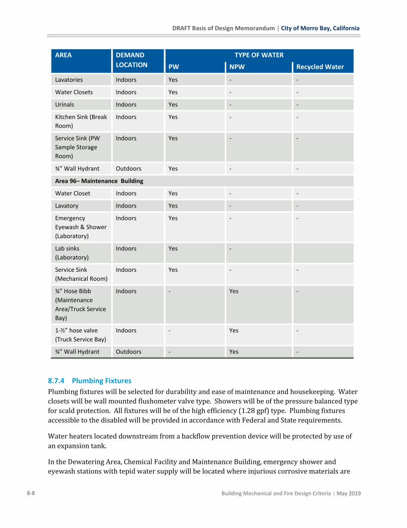
DRAFT Basis of Design Memorandum | City of Morro Bay, California
8-8 Building Mechanical and Fire Design Criteria | May 2019
AREA DEMAND
LOCATION
TYPE OF WATER
PW NPW Recycled Water
Lavatories Indoors Yes - -
Water Closets Indoors Yes - -
Urinals Indoors Yes - -
Kitchen Sink (Break
Room)
Indoors Yes - -
Service Sink (PW
Sample Storage
Room)
Indoors Yes - -
¾” Wall Hydrant Outdoors Yes - -
Area 96– Maintenance Building
Water Closet Indoors Yes - -
Lavatory Indoors Yes - -
Emergency
Eyewash & Shower
(Laboratory)
Indoors Yes - -
Lab sinks
(Laboratory)
Indoors Yes -
Service Sink
(Mechanical Room)
Indoors Yes - -
¾” Hose Bibb
(Maintenance
Area/Truck Service
Bay)
Indoors - Yes -
1-½” hose valve
(Truck Service Bay)
Indoors - Yes -
¾” Wall Hydrant Outdoors - Yes -
8.7.4 Plumbing Fixtures
Plumbing fixtures will be selected for durability and ease of maintenance and housekeeping. Water
closets will be wall mounted flushometer valve type. Showers will be of the pressure balanced type
for scald protection. All fixtures will be of the high efficiency (1.28 gpf) type. Plumbing fixtures
accessible to the disabled will be provided in accordance with Federal and State requirements.
Water heaters located downstream from a backflow prevention device will be protected by use of
an expansion tank.
In the Dewatering Area, Chemical Facility and Maintenance Building, emergency shower and
eyewash stations with tepid water supply will be located where injurious corrosive materials are
City of Morro Bay, California | DRAFT Basis of Design Memorandum
| Building Mechanical and Fire Design Criteria 8-9
handled or stored, or for general work area safety. The emergency fixtures will be located in well
lit, highly visible, accessible locations on the same level as the hazard with an obstruction free
travel path. The station will be plumbed to a tepid water supply as described in the water supply
piping paragraph designed to provide 15 minutes of flow. A floor drain will be located under the
emergency shower. Each emergency shower and eyewash station will have an alarm device for
local and remote alarms. The local alarm will consist of an audible and visible alarm light.
In the Maintenance Building, a water closet and lavatory will be provided in the restroom, a
janitor's sink and domestic water heater will be provided in the Storage Room.
In the Operations Building, water closets, urinals, and lavatories will be provided in the restrooms
as necessary, a janitor's sink and domestic water heater will be provided in the Janitor's Closet, and
a kitchen sink will be provided in the Break Room.
In the Chemical Facility, emergency shower and eyewash fixtures will be provided with tepid water
supply as required. Emergency fixtures will be of the frost proof type with insulated and heat
traced tepid water supply. Emergency fixtures will also be provided outside adjacent the chemical
truck unloading stations.
8.7.5 Natural Gas Piping System
The City will coordinate the new natural gas supply to the site. Natural gas piping and pressure
regulation will be provided at each building for building heat, domestic and process water heaters
as necessary. The gas meter will be provided and located by the gas utility. A pressure reducing
valve will be located adjacent to the facility to reduce gas pressure before entry into the building.
The natural gas building service entrances will be located and protected from accidental damage by
equipment, settlement, or vibration. The natural gas service into the facility will be located above
grade. Piping materials will consist of polyethylene pipe with butt fusion joints for buried sizes 3
inch and larger and socket fusion joints for buried sizes 2 inch and smaller. For above grade and
interior locations, pipe will consist of schedule 40 black steel with butt welding fittings for 2-1/2
inch and larger and socket welding or malleable iron fittings for 2 inch and smaller
8.7.6 Onsite Recycled Water Piping System
Recycled water will be used for irrigation, scum sprays, and exterior washdown where appropriate.
The on-site recycled water system will operate at approximately 75 psi. Water pressure reducing
valves will not be required.
8.7.7 Product Water System
Product water will not be used on the site.
8.8 HEATING, VENTILATION, AND AIR CONDITIONING The following is a description of the HVAC systems.
8.8.1 Indoor Design Conditions
The following Table describes the indoor design conditions and ventilation rates for each room
within the buildings.
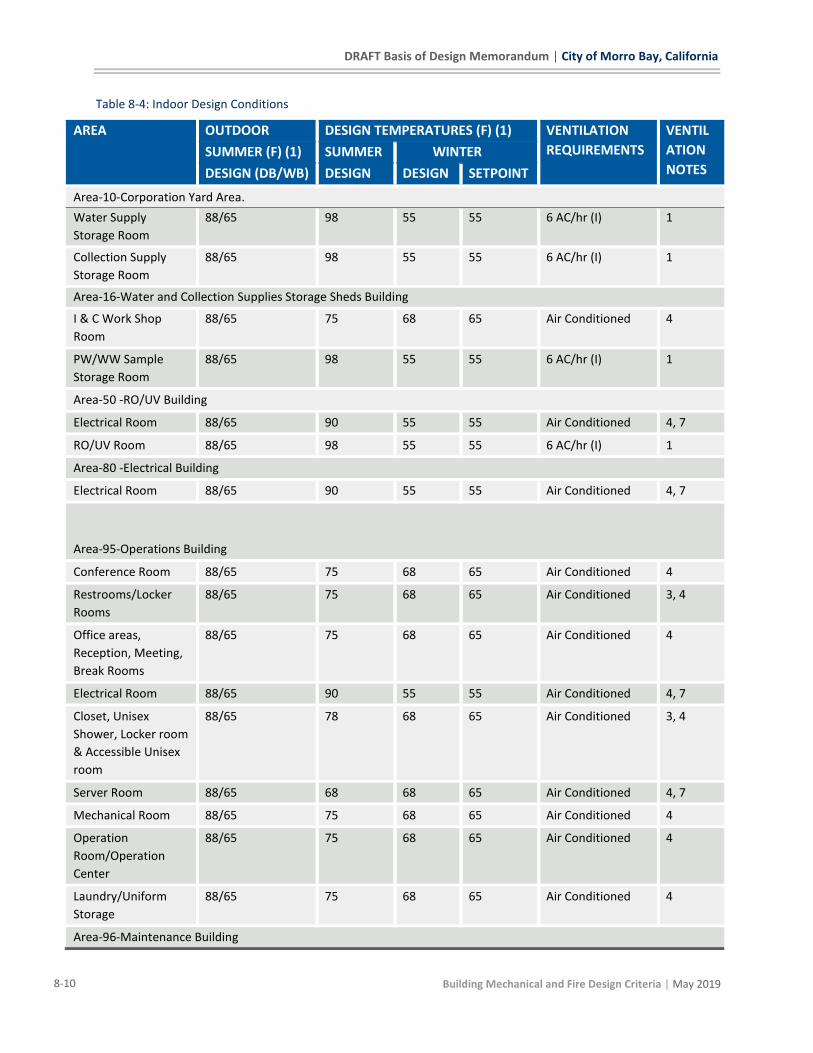
DRAFT Basis of Design Memorandum | City of Morro Bay, California
8-10 Building Mechanical and Fire Design Criteria | May 2019
Table 8-4: Indoor Design Conditions
AREA OUTDOOR DESIGN TEMPERATURES (F) (1) VENTILATION
REQUIREMENTS
VENTIL
ATION
NOTES SUMMER (F) (1) SUMMER WINTER
DESIGN (DB/WB) DESIGN DESIGN SETPOINT
Area-10-Corporation Yard Area.
Water Supply
Storage Room
88/65 98 55 55 6 AC/hr (I) 1
Collection Supply
Storage Room
88/65 98 55 55 6 AC/hr (I) 1
Area-16-Water and Collection Supplies Storage Sheds Building
I & C Work Shop
Room
88/65 75 68 65 Air Conditioned 4
PW/WW Sample
Storage Room
88/65 98 55 55 6 AC/hr (I) 1
Area-50 -RO/UV Building
Electrical Room 88/65 90 55 55 Air Conditioned 4, 7
RO/UV Room 88/65 98 55 55 6 AC/hr (I) 1
Area-80 -Electrical Building
Electrical Room 88/65 90 55 55 Air Conditioned 4, 7
Area-95-Operations Building
Conference Room 88/65 75 68 65 Air Conditioned 4
Restrooms/Locker
Rooms
88/65 75 68 65 Air Conditioned 3, 4
Office areas,
Reception, Meeting,
Break Rooms
88/65 75 68 65 Air Conditioned 4
Electrical Room 88/65 90 55 55 Air Conditioned 4, 7
Closet, Unisex
Shower, Locker room
& Accessible Unisex
room
88/65 78 68 65 Air Conditioned 3, 4
Server Room 88/65 68 68 65 Air Conditioned 4, 7
Mechanical Room 88/65 75 68 65 Air Conditioned 4
Operation
Room/Operation
Center
88/65 75 68 65 Air Conditioned 4
Laundry/Uniform
Storage
88/65 75 68 65 Air Conditioned 4
Area-96-Maintenance Building
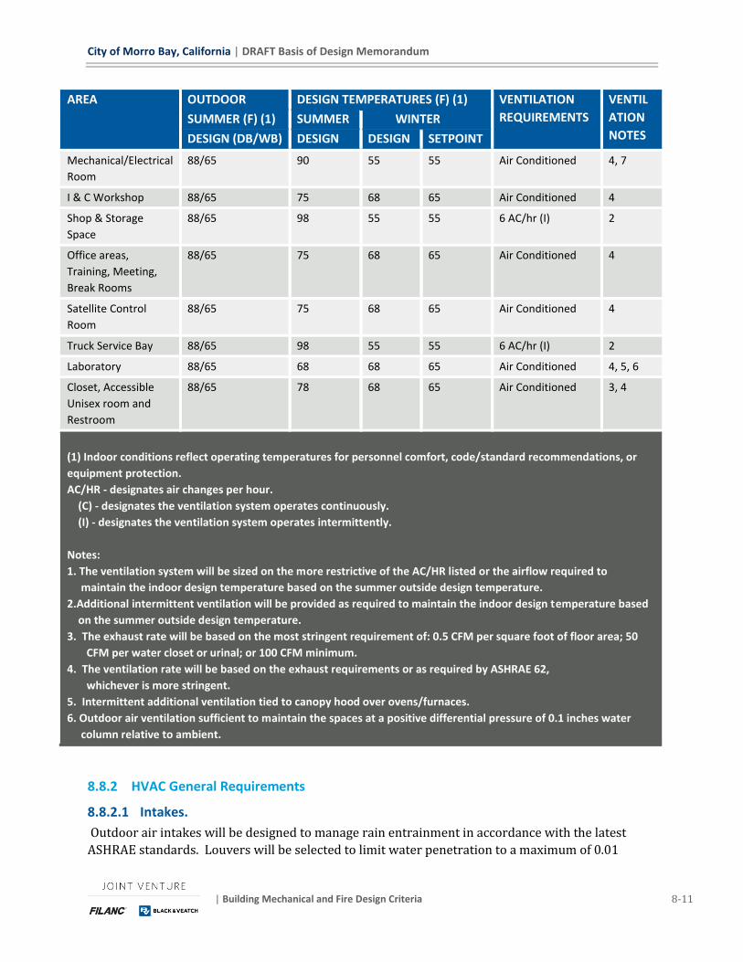
City of Morro Bay, California | DRAFT Basis of Design Memorandum
| Building Mechanical and Fire Design Criteria 8-11
AREA OUTDOOR DESIGN TEMPERATURES (F) (1) VENTILATION
REQUIREMENTS
VENTIL
ATION
NOTES SUMMER (F) (1) SUMMER WINTER
DESIGN (DB/WB) DESIGN DESIGN SETPOINT
Mechanical/Electrical
Room
88/65 90 55 55 Air Conditioned 4, 7
I & C Workshop 88/65 75 68 65 Air Conditioned 4
Shop & Storage
Space
88/65 98 55 55 6 AC/hr (I) 2
Office areas,
Training, Meeting,
Break Rooms
88/65 75 68 65 Air Conditioned 4
Satellite Control
Room
88/65 75
68 65 Air Conditioned 4
Truck Service Bay 88/65 98 55 55 6 AC/hr (I) 2
Laboratory 88/65 68 68 65 Air Conditioned 4, 5, 6
Closet, Accessible
Unisex room and
Restroom
88/65 78 68 65 Air Conditioned 3, 4
(1) Indoor conditions reflect operating temperatures for personnel comfort, code/standard recommendations, or
equipment protection.
AC/HR - designates air changes per hour.
(C) - designates the ventilation system operates continuously.
(I) - designates the ventilation system operates intermittently.
Notes:
1. The ventilation system will be sized on the more restrictive of the AC/HR listed or the airflow required to
maintain the indoor design temperature based on the summer outside design temperature.
2.Additional intermittent ventilation will be provided as required to maintain the indoor design temperature based
on the summer outside design temperature.
3. The exhaust rate will be based on the most stringent requirement of: 0.5 CFM per square foot of floor area; 50
CFM per water closet or urinal; or 100 CFM minimum.
4. The ventilation rate will be based on the exhaust requirements or as required by ASHRAE 62,
whichever is more stringent.
5. Intermittent additional ventilation tied to canopy hood over ovens/furnaces.
6. Outdoor air ventilation sufficient to maintain the spaces at a positive differential pressure of 0.1 inches water
column relative to ambient.
8.8.2 HVAC General Requirements
8.8.2.1 Intakes.
Outdoor air intakes will be designed to manage rain entrainment in accordance with the latest
ASHRAE standards. Louvers will be selected to limit water penetration to a maximum of 0.01

DRAFT Basis of Design Memorandum | City of Morro Bay, California
8-12 Building Mechanical and Fire Design Criteria | May 2019
oz/ft2 (3 g/m2) of louver free area at the maximum intake velocity. Corrosion resistant screens
will cover the openings with openings of 1/2 inch.
8.8.2.2 Air Filtration.
Outdoor air will be filtered for air-conditioned areas. Filtration will consist of 2-inch disposable
pleated media filters with a minimum efficiency reporting value (MERV) based on ASHRAE 52.2
guidelines of at least 6.
8.8.2.3 Internal Load Factors.
Heating and cooling loads will be calculated in accordance with ASHRAE Standards. Internal heat
gains will be included in the calculations based on the following:
◼ Lighting: 1.3 watts/sq ft (unless otherwise indicated)
◼ Equipment: Equipment heat loss from equipment anticipated to operate simultaneously.
8.8.2.4 Ductwork.
Ductwork will be sized for 0.08-inch water column per 100 feet for a friction loss. Ductwork will be
insulated for air conditioning systems, outside air, and heating systems. Insulation will consist of
duct liner tested to be resistant to mold growth and erosion under a standardized test method.
Insulated plenums will be externally insulated and include drain provisions for removal of any
moisture that may carryover through the outside air louver.
8.8.2.5 Outside Air.
Air conditioning and ventilation will be provided in offices and other normally occupied areas in
accordance with ASHRAE Standards 55 and 62. Buildings containing WRF processes and equipment
will be provided with supply air and exhaust air ventilation in accordance with NFPA 820.
8.8.3 Heating Systems
Space heating will be provided by either individual natural gas or electric unit heaters in the
process areas. Electrical rooms will be provided with electric unit heaters. The heaters will be
located to provide uniform space heating of the area served. Each unit heater will be controlled by
an adjustable wall mounted digital thermostat.
8.8.4 Ventilation Systems
In the RO/UV Building, the ventilation systems will consist of intermittent systems. The makeup air
unit will be controlled by a local "ON-OFF" selector switch and each power roof ventilator/ wall
mounted propeller will be controlled by a local "ON-OFF-AUTO" selector switch. When each power
roof ventilator selector switch is in the "AUTO" position, the power roof ventilator will be
interlocked with the makeup air unit. The makeup air unit will be filtered and tempered to the
room design temperature before supplied to the space. A thermostat will modulate the discharge
air temperature to the design space temperature.
In the remaining process areas, the intermittent ventilation systems will consist of wall mounted
propeller fans or inline duct fans for exhaust and supply fan, with louvers for air intake. Air filters
will be installed inside the duct. The intermittent systems will serve the process and storage areas.

City of Morro Bay, California | DRAFT Basis of Design Memorandum
| Building Mechanical and Fire Design Criteria 8-13
Each fan will be controlled by a local "ON-OFF-AUTO" selector switch. When the selector switch is
in the "AUTO" position, the fan will be interlocked with the thermostat.
8.8.5 Air Conditioning Systems
In the Operation Building, the air conditioning system will consist of a variable air volume,
packaged grade mounted air conditioning/heat pumps. The air conditioning unit/heat pump will be
provided with a backup emergency electric heating coil. Each unit will be controlled by a remote
wall mounted temperature sensor to maintain the desired space temperature. The Server Room
will be served by a split system air conditioner.
The Men's and Women's Toilet/Locker rooms and the Janitors Closet/Mechanical/Electrical room
will be exhausted by inline duct fans. Each fan will be controlled by a local "ON-OFF-AUTO" selector
switch. When the selector switch is in the "AUTO" position, the fan will be interlocked with the heat
pump serving this area of the building
The air conditioning system for the Maintenance (Control and I&C Workshop spaces) and RO/UV
Building Electrical Rooms will consist of single zone, constant volume packaged grade mounted air
conditioning/heat pumps. The heat pumps will not be provided with backup emergency electric
heating coils due to the mild climate and heat generated within the rooms. Each unit will be
controlled by a remote wall mounted thermostat to maintain the desired space temperature. An
economizer system will be provided to allow the use of outdoor air for cooling the space when
ambient temperatures are suitable.
In Maintenance Building the packaged air conditioning unit for the Laboratory will be sized to
handle the additional cooling load of any outdoor air required for fume or canopy hoods. Any fume
hoods required will be grade mounted with stacks discharging above the building.
The air conditioning system for the pre-engineered Electrical Building will be a packaged grade
mounted air conditioning or split system air conditioner. Full 100% HVAC system redundancy will
be provided.
For areas described to have Full 100% HVAC system redundancy, two units each sized to provide
the total heating and cooling loads will be used to maintain the indoor design conditions. Only one
unit will operate at a time and the units will alternate in operation so that the run times for each
unit remain approximately the same. In the event that a single unit fails, the other unit will start
and maintain the desired space conditions.
8.8.6 Building Control Systems
The HVAC controls will consist of automatic industrial grade electromechanical and electronic
controls. Control component enclosures will be selected based on the environment where they are
installed. Typical controls will consist of the following:
◼ Differential pressure indication across supply and exhaust fans designed to operate continuously
to indicated fan flow or failure. Where insufficient differential pressure occurs due to limited
ductwork, motor current switches will be used.
DRAFT Basis of Design Memorandum | City of Morro Bay, California
8-14 Building Mechanical and Fire Design Criteria | May 2019
◼ Duct mounted smoke detectors where systems have airflows greater than 2000 CFM and are
capable of spreading smoke beyond the enclosing walls, floors and ceilings of the room or space
in which the smoke is generated.
◼ Differential pressure gauge and differential pressure switch with alarm across air filters.
◼ Electric thermostats for control of intermittent ventilation systems to start and stop equipment
operation.
◼ Electric thermostats or electronic sensors to control heating equipment for maintaining the
leaving air temperature within the design temperature range.
◼ Electric thermostats for detection and alarming of low air temperatures.
◼ Programmable electric thermostats for control of packaged air conditioning systems.
◼ Local ON-OFF control stations to be provided for vault ventilation systems.
A microprocessor-based stand-alone system or building automation system (BAS) is anticipated
only for the Operations Building. The remainder of the plant HVAC systems can be designed to be
on the same BAS system if the Client prefers. This would allow for better remote operation of the
facility in the future.
8.9 FIRE PROTECTION DESIGN
8.9.1 Applicable Codes and Standards
The fire protection system design will conform to the latest editions of the following applicable
standards and codes:
◼ California Building Code (with local jurisdiction amendments)
◼ California Fire Code (with local jurisdiction amendments)
◼ National Fire Protection Association (NFPA)
◼ Standard for Fire Protection in Wastewater Treatment and Collection Facilities (NFPA 820)
◼ Standard for the Installation of Private Fire Service Mains and Their Appurtenances (NFPA 24)
◼ Life Safety Code (NFPA 101)
◼ Fire Alarm Signaling (NFPA 72)
8.9.2 Fire Protection
Fire protection designed to meet the requirements of the National Fire Protection Association
(NFPA) will be provided where indicated on the Code Classification Table in the drawings. Fire
protection will be installed based upon the 2016 edition of California Building and Fire Codes along
with local amendments.
All new WRF buildings were analyzed for the fire suppression system requirements. Per local
amendments to State adopted code, sprinkler systems are required inside all buildings exceeding
1000 square foot fire areas; however, California Government Code Section 53091(d) allows
construction of facilities for the production, storage, treatment, or transmission of water or
wastewater by local agency to not comply with building ordinances of county or city. This allows

City of Morro Bay, California | DRAFT Basis of Design Memorandum
| Building Mechanical and Fire Design Criteria 8-15
all buildings of the project to only comply with California Building and Fire Codes, which does not
require any project building to be protected with automatic sprinkler system based on building
floor area or occupancy hazard. A clarification and reconfirmation from the authority having
jurisdiction (AHJ) is required to finalize the requirement of sprinkler system based on size of the
buildings.
The following will be used for the building and sprinkler design:
◼ All hazardous chemicals will be stored outside buildings with sufficient fire separation as
required by the CBC, and thus no sprinkler protection will be provided for outdoor storage.
◼ In buildings without sprinklers, the exterior wall openings will be placed every 50 feet on at least
one side.
◼ Maximum fire flow requirements for each project building will be 1500 gpm for a maximum 2
hour duration.
◼ Dedicated electrical rooms will be provided with smoke detection systems.
◼ Standpipes are not expected to be required for any of the buildings, although this will be
evaluated further in detail design.
The following will be used for the fire hydrant and fire water main design:
◼ Every building will be provided with a hydrant within 400 feet of all portions of the building and
a minimum of 40 feet away from the building so it can be operated by the Fire Response Team
during an emergency.
◼ Fire hydrants will be provided on the access roads with bollard having sufficient clearance to
protect against mechanical damage.
◼ The farthest hydrant along the fire water main will be dedicated for a minimum of 1500 gpm fire
flow and a minimum 20 psi residual pressure.
◼ The fire main will be sized to deliver the flow and pressure requirements listed in this section
and designed per NFPA 24.
◼ Fire pumper trucks will boost the hydrant water pressure to required level using truck pump
station.
◼ All control valves on the water supply piping will be electrically monitored by fire alarm control
unit.
8.9.3 Water Supply
Initial assessment of city potable firewater supply to the site indicates that adequate fire water flow
is available for largest flow required for fire flow or sprinkler system operation. Available water
supply information furnished by the City is summarized in
Table 8-5 below.
Table 8-5: Available Water Supply Flow & Pressure
CRITERIA VALUE
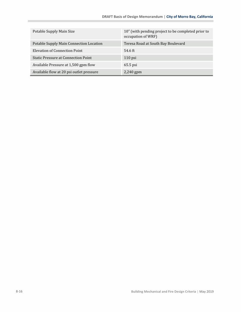
DRAFT Basis of Design Memorandum | City of Morro Bay, California
8-16 Building Mechanical and Fire Design Criteria | May 2019
Potable Supply Main Size 10” (with pending project to be completed prior to
occupation of WRF)
Potable Supply Main Connection Location Teresa Road at South Bay Boulevard
Elevation of Connection Point 54.6 ft
Static Pressure at Connection Point 110 psi
Available Pressure at 1,500 gpm flow 65.5 psi
Available flow at 20 psi outlet pressure 2,240 gpm
City of Morro Bay, California | DRAFT Basis of Design Memorandum
| Electrical Design Criteria 9-1
9 Electrical Design Criteria
9.1 GENERAL ELECTRICAL DESIGN CRITERIA This section presents the design criteria for the electric power system for the Project. The intent is
to provide a safe and reliable means of delivering and distributing power while ensuring ease of
maintenance as much as possible. The following criteria also address other electrical requirements
that are not specifically related to power delivery.
9.2 CODES AND STANDARDS Electrical design will conform to the latest editions of the following applicable standards and codes:
◼ State of California, Title 24, Part 3 Electrical Code
◼ State of California, Title 24, Part 6 Energy Code
◼ State of California, Title 8 Industrial Relations, Chapter 4, Electrical Safety Orders
◼ National Electrical Code (NEC – NFPA 70)
◼ National Electrical Safety Code (NESC)
◼ Life Safety Code (NFPA 101 HB)
Standards and codes of the following organizations will also govern, where applicable:
◼ American National Standards Institute (ANSI)
◼ Illuminating Engineering Society (IES)
◼ International Society of Automation (ISA)
◼ National Electrical Manufacturers Association (NEMA)
◼ National Fire Protection Association (NFPA)
◼ Institute of Electrical and Electronics Engineers (IEEE)
◼ Insulated Cable Engineers Association (ICEA)
◼ Occupational Safety and Health Administration (ASTM)
◼ Underwriters Laboratory (UL)
9.3 POWER DISTRIBUTION DESIGN The design of the power distribution system for the Project will follow the current design
guidelines recognized by IEEE and current industry standards.
9.4 ELECTRICAL SERVICE AND DISTRIBUTION SYSTEM The new electrical service will be provided by Pacific Gas & Electric (PG&E). A 12KV power line
from PG&E will be via an overhead utility distribution line adjacent to plant property and will be
routed underground to an on-site pad mounted PG&E furnished outdoor transformer. The PG&E
transformer will connect to the PG&E metering cabinet inside the Electrical Building and feed a new
480Y/277 V, three-phase, four-wire, 2000A, indoor automatic transfer switch (ATS) in the

DRAFT Basis of Design Memorandum | City of Morro Bay, California
9-2 Electrical Design Criteria | May 2019
Electrical Building. The ATS will have an emergency power source connection from 1MW, 480V,
three-phase, four-wire generator which will be located outdoor and adjacent to Electrical Building.
The ATS will feed a 2000A indoor switchboard located in the Electrical Building. The switchboard
will have radial feed to 3 MCC’s with 2 of them located in the Electrical Building and one of them
located in the RO Building.
The switchboard will also include an 800A spare breaker for future PV connection.
The MCC’s will feed power panels, which will contain feeder breakers to power process loads and
miscellaneous 480 volt building and auxiliary loads not requiring a motor starter within the MCC.
The MCC will use NEMA type motor starters and feeder breakers to feed the power panel and the
lighting transformer.
For small loads requiring lower voltages, a dry-type transformer will be located in the Electrical
Building and will step the voltage down to a 208Y/120 volt, three-phase panelboard. The
panelboard will distribute power to HVAC, lighting, receptacle, and other miscellaneous small loads.
The lighting transformer and panelboard will be mounted external to the MCC.
Control panels, as applicable, will conform to UL 508A. This includes requirements for
conformance to the latest short circuit equipment rating requirements. All free standing electrical
equipment will be installed on concrete housekeeping pads.
9.5 DISTRIBUTION AND UTILIZATION VOLTAGES The following distribution and equipment utilization voltages and ratings will generally be used.
Depending on the specific equipment requirements determined in design, there may be some
exceptions.
Plant distribution: 480Y/277 volts, three-phase
Motors, 1/2 hp and larger: 480 volts, three-phase
Motors, less than 1/2 hp: 120 volts, single-phase
Motor control: 120 volts, single-phase
Lighting: 120 volts, single-phase
Convenience outlets: 120 volts, single-phase
Instrumentation and Control: 24VDC
9.6 STANDBY POWER A stand-by rated diesel fueled engine-generator will be provided for the project in the event utility
supplied power is not available. The engine-generator package will consist of an engine-generator,
control panel, cooling system, sub-base fuel storage tank, and accessory items all installed outside
in a weather-proof enclosure on a concrete base.
A double walled sub-base type fuel storage tank will be used to supply fuel to the engine-generator.
The sub-base tank will meet NFPA requirements and have sufficient capacity for a minimum of 24

City of Morro Bay, California | DRAFT Basis of Design Memorandum
| Electrical Design Criteria 9-3
hours of operation of the engine-generator at full capacity. The fuel storage tank will be installed
underneath the engine-generator, inside the enclosure. The tank will be equipped with leak
detection and fill box to contain any accidental spillage during filling of the tank.
The engine-generator size is based on operating the treatment facility at 1 mgd capacity.
Preliminary sizing estimates the unit to be rated at 400 kW. An ATS will be furnished to transfer
between utility power and generator power.
9.7 ELECTRICAL EQUIPMENT DESIGN CRITERIA The following general requirements and guidelines will be used in the design of electrical
equipment and support systems.
9.7.1 480 Volt Switchboard
Indoor, NEMA 1 rated switchboard will be used for the project. Control cabling will be insulated and
rated for 600V.
Circuit powering the switchboard will be 480 V, three-phase. All equipment will be rated to handle
short circuit currents equal to or greater than the available fault current. The switchboard will have
power main breakers with solid-state trip units with long-time (L), short-time (S), instantaneous (I)
and ground-fault (G) protection functions. Downstream distribution breakers will be molded case
type with solid-state adjustable trip units to improve coordination and downstream arc flash
characteristics. Surge protection devices (SPDs) will be provided.
The switchboard will have a spare breaker connection for the future PV system.
9.7.2 480 Volt Motor Control Center and Starters
Indoor, NEMA 1 rated MCC will be used for the project. Internal and external monitoring and
control of MCC devices such as motor starters and HMI control screens will be via hardwiring. MCC
power monitoring units will have Modbus/Ethernet network protocol to connect to the Plant
Control System. Control cabling installed within the MCC will be insulated and rated for 600V.
Feeder circuit powering the MCC originating from the switchboard feeder breaker will be 480 volt,
three-phase, three-wire. The MCC will have a tin-plated copper phase bus and a copper ground bus.
MCC will be a single bus configuration and will be rated to handle short circuit currents equal to or
in excess of the available fault current. Customer power quality monitoring equipment will be
included in the MCC to connect metering data to the Plant Control System. The MCC main breaker
will be molded case type with solid-state trip units with LSI protection functions. The MCC main
breaker will also be provided with ground-fault protection when required by the NEC. Distribution
breakers on the MCC will be molded case type with solid state or thermal-magnetic trip units. MCC
will measure 20 inches deep. Some spares and spaces will be allotted. Surge protection devices
(SPDs) will be provided integral to the assembly.
Except for packaged equipment and HVAC equipment, motor starters will generally be located
within the MCC. Starters will include a GREEN indicated lamp for RUNNING (ON), a RED indicating
lamp for OFF, and an AMBER indicating lamp for trouble or FAILURE (where applicable). All pilot
lamps will be push-to-test type. Only full sized NEMA contactors will be used for all systems. IEC
contactors will not be acceptable.
DRAFT Basis of Design Memorandum | City of Morro Bay, California
9-4 Electrical Design Criteria | May 2019
9.7.3 Motors and Variable Frequency Drives
Motors will be specified with “NEMA Premium” high efficiency ratings. Motor enclosures will be
suitable for the environment in which they are installed. All motors driven from variable frequency
drives (VFDs) will be inverter-duty rated and will be rated for such applications. The heaters will
be designed to operate on 120-volt ac power from the associated motor starter or VFD.
VFDs will be pulse width modulated type. VFDs will be fed from a dedicated 480 volt, three-phase
feeder. Drives for motors smaller than 100 hp may use 6-pulse type.
9.7.4 Power Transformers
Transformers that supply 208Y/120 volts or 240/120 volts for lighting requirements will be dry
type with copper windings and suitable for the area in which they are to be located. Transformers
will be industry standard sizes.
9.7.5 Panelboards
Power distribution panelboards or power centers, if required, will be 480, three-phase, three, with
a copper bus and a main circuit breaker.
Lighting panelboards will be either 208Y/120 volts, three-phase, four wire type or 240/120 volts,
single phase, three-wire type, with a copper bus and a main circuit breaker sized to match the
lighting transformer capacity.
Each panelboard will have a minimum of 20 percent of its capacity reserved for spare breakers with
spaces, bus work, and terminations to complete the standard sized panelboard. SPDs will be
provided integral to each panel assembly.
9.7.6 Receptacles
Convenience receptacles for general service will be located on walls or columns. Provisions for
receptacles at all air conditioning units and air handling units will be made as required by NEC.
Convenience receptacles will generally be mounted 18-inches above floors, except outdoors or in
rooms where equipment could be hosed down. Receptacles in such areas will be mounted
48-inches above the floor or grade. Weatherproof in-use receptacles will be utilized outdoor, and in
wet and damp locations. Receptacles installed outdoors will be provided with ground fault circuit
interrupting capability.
9.7.7 Raceways and Cable
Specific types of raceways will be chosen for locations vulnerable to damage by moisture, extreme
temperature, or corrosion, and considering voltage and cost. An underground duct bank consisting
of direct buried schedule 40 PVC type conduits for non-traffic area and concrete encased schedule
40 PVC type conduits for traffic area will be provided for most circuits that are routed outside of
buildings. Duct banks will include spare conduits. The following systems will be separately
grouped in duct banks:
◼ Power and discrete control wiring 600 volts and below.
◼ Process instrumentation analog and communication wiring, including 24-volt discrete signals,
and LAN/Data Highway computer circuits.
City of Morro Bay, California | DRAFT Basis of Design Memorandum
| Electrical Design Criteria 9-5
The following general guidelines will be used for raceway sizing, selection, and installation:
◼ Conduit will be sized based on XHHW-2 insulation for all conductors 600 volts and less.
◼ The minimum diameter of all conduit will be 3/4-inch.
◼ Raceways in duct banks will not be smaller than 2-inches.
◼ Exterior, exposed conduit will be PVC-Coated galvanized rigid steel.
◼ Interior, exposed conduit in non-corrosive areas will be rigid galvanized steel.
◼ Interior, exposed conduit in corrosive areas will be Schedule PVC-Coated galvanized rigid steel.
◼ Exterior, underground, direct buried and concrete-encased conduit will be schedule 40 PVC.
Power and control wiring rated 600 volts and less will be stranded copper conductors with XHHW-
2 insulation. Lighting and receptacle circuit wiring rated 600 volts and less will be single solid
conductor copper with THHN/THHW insulation. Individual 14 AWG conductors will be used for
discrete control circuits, unless it is practical to use multi conductor cables to group control circuits.
Cables will have 600-volt insulation.
Power cable to equipment controlled by an variable frequency drive operating 600 volts or less will
be 2000-volt VFD cable with stranded copper conductors and XLP insulation.
Twisted shielded pair control cable with 16 AWG individual stranded copper conductors, PVC
insulation, and an aluminum Mylar tape shield around the pair will be used for analog signals. Multi
pair cables will be used where grouping of circuits is practical. Cables will have 600-volt insulation.
9.8 GROUND AND LIGHTNING PROTECTION The electrical system and equipment will be grounded in compliance with the NFPA National
Electrical Code (NEC). Conductors will be at least 4/0 AWG copper, minimum, for interconnecting
ground rods and for connections to transformers and MCC. A grounding ring will be provided for
each building. Electrical equipment, devices, panelboards, and metallic raceways that do not carry
current will be connected to the ground ring as well as building steel and metal water piping.
Transformer neutrals of wye connected transformers will be solidly grounded through a grounding
electrode conductor connected to the grounding electrode system.
A lightning risk analysis will be performed during final design to determine if a lightning protection
system is required. Any lightning protection system installed will meet the requirements of NFPA
780, Standard for Lightning Protection Systems. Lightning protection system will be specified to be
designed and installed through a UL approved lighting protection system supplier. It is anticipated
that the lightning protection system will consist of roof-mounted copper lightning aerial terminals
interconnected by bare copper wire. This lightning protection matrix will be secured with copper
mounting hardware and bonded to the respective building’s ground ring via bare copper wire run
down the exterior of the building.
9.9 LIGHTING DESIGN CRITERIA LED lighting systems will be used for all areas. Illumination levels in the Electrical Building will be
provided following the recommended levels suggested in the Illuminating Engineering Society (IES)
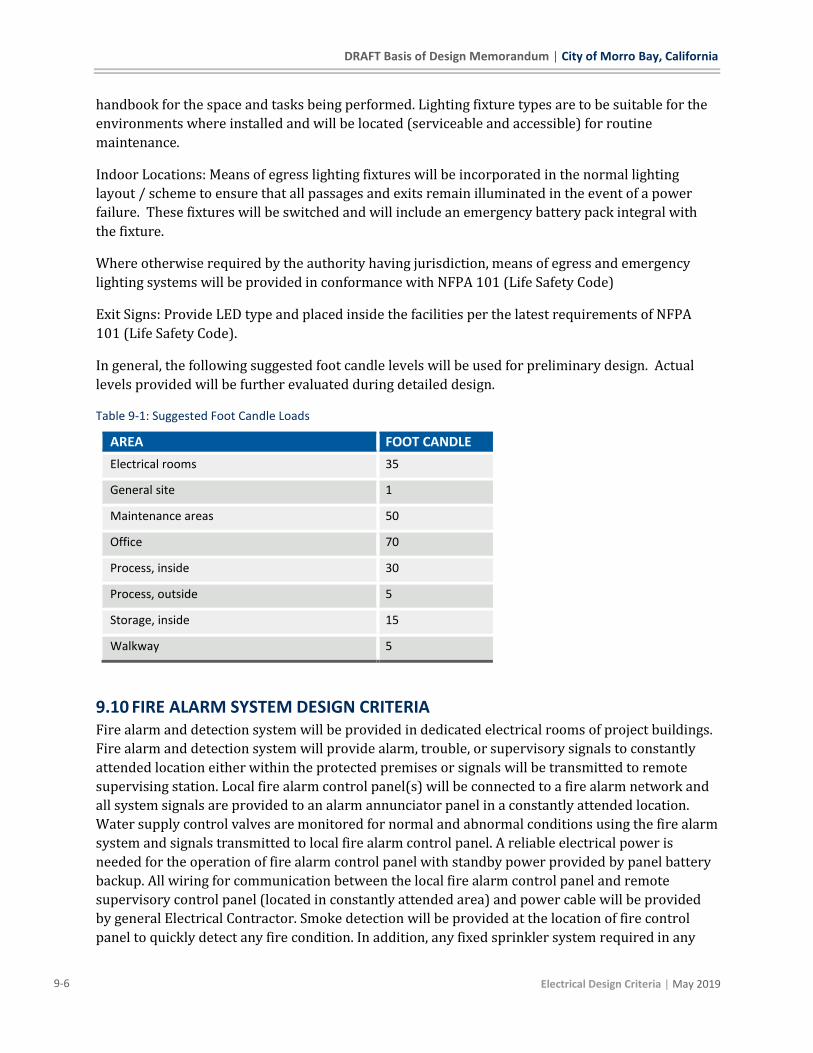
DRAFT Basis of Design Memorandum | City of Morro Bay, California
9-6 Electrical Design Criteria | May 2019
handbook for the space and tasks being performed. Lighting fixture types are to be suitable for the
environments where installed and will be located (serviceable and accessible) for routine
maintenance.
Indoor Locations: Means of egress lighting fixtures will be incorporated in the normal lighting
layout / scheme to ensure that all passages and exits remain illuminated in the event of a power
failure. These fixtures will be switched and will include an emergency battery pack integral with
the fixture.
Where otherwise required by the authority having jurisdiction, means of egress and emergency
lighting systems will be provided in conformance with NFPA 101 (Life Safety Code)
Exit Signs: Provide LED type and placed inside the facilities per the latest requirements of NFPA
101 (Life Safety Code).
In general, the following suggested foot candle levels will be used for preliminary design. Actual
levels provided will be further evaluated during detailed design.
Table 9-1: Suggested Foot Candle Loads
AREA FOOT CANDLE
Electrical rooms 35
General site 1
Maintenance areas 50
Office 70
Process, inside 30
Process, outside 5
Storage, inside 15
Walkway 5
9.10 FIRE ALARM SYSTEM DESIGN CRITERIA Fire alarm and detection system will be provided in dedicated electrical rooms of project buildings.
Fire alarm and detection system will provide alarm, trouble, or supervisory signals to constantly
attended location either within the protected premises or signals will be transmitted to remote
supervising station. Local fire alarm control panel(s) will be connected to a fire alarm network and
all system signals are provided to an alarm annunciator panel in a constantly attended location.
Water supply control valves are monitored for normal and abnormal conditions using the fire alarm
system and signals transmitted to local fire alarm control panel. A reliable electrical power is
needed for the operation of fire alarm control panel with standby power provided by panel battery
backup. All wiring for communication between the local fire alarm control panel and remote
supervisory control panel (located in constantly attended area) and power cable will be provided
by general Electrical Contractor. Smoke detection will be provided at the location of fire control
panel to quickly detect any fire condition. In addition, any fixed sprinkler system required in any

City of Morro Bay, California | DRAFT Basis of Design Memorandum
| Electrical Design Criteria 9-7
project building will be monitored by local fire alarm control panel to detect and alarm anytime
sprinkler system is activated due to fire.
Fire alarm system will be provided to meet current code requirements. Design of the fire alarm
system will adhere to NFPA 72. Final design of fire alarm system will be via performance
specification in the contract. A local fire alarm system supplier will be contracted to determine all
local fire code requirements and submitting a complete design with complies with those
requirements.
9.11 HAZARDOUS AREAS NFPA 820 will be utilized to determine the area classifications. The design will include specification
for the components and installation to meet these requirements, including but not limited to seal off
fittings, junction boxes, disconnects, light fixtures, combustible gas detectors (CGD), audible and
visual alarms, ventilation systems and control stations.
The selection of type and location of CGD units shall be performed by a qualified person as
described by NFPA 70. The units shall be placed in accordance to the appropriate table in NFPA
820. The items selected shall be set to 10% of lower explosive limit (LEL) unless otherwise directed
by local AHJ, and connected to the alarm signaling system.
Ventilation audible and visual alarms shall be installed both within the space and be tied to the
plant control system.
9.12 TELEPHONE AND COMMUNICATION DESIGN CRITERIA A telephone and/or data system will be installed as required. Data communication links for the
Process Control Network, Office Network, and Off-site connections area described in
Instrumentation and Controls Design section. Conduit installation and required equipment
installation will be included as determined by the detailed Instrumentation & Control network
design.
9.13 SECURITY SYSTEM DESIGN CRITERIA A security control panel and annunciator will be installed to monitor the facilities on site.
Intrusion/proximity switches will be provided for the building exterior doors. Card key access
control will be provided for the building main entrance locations and provisions for the electronic
access system will be installed. All security signals will be routed to the security control panel.
Fixed Closed Circuit Television (CCTV) cameras will also be installed for each building. Pan-Tilt-
Zoon (PTZ) camera will be installed at the site gate entrance location. PTZ CCTV camera will be
provided with two 1” conduits for routing separate 120 V power circuit and video signal which the
fixed CCTV camera will be provided with one 1” conduits for the power and video signal. The
power for the fixed CCTV will be from the Ethernet switch. Video signals will be routed to the
communications cabinet.
A motor controlled road security gate will be provided to grant access to the site.
DRAFT Basis of Design Memorandum | City of Morro Bay, California
9-8 Electrical Design Criteria | May 2019
9.14 CALCULATION AND ANALYSIS REQUIREMENTS The following calculations and analyses will be performed during final design or during the
construction of the facility as indicated below.
9.14.1 Load Analysis
A load analysis will be prepared during final design to help plan the power distribution system.
Major loads, including the estimated values of connected loads and peak running loads will be
calculated. Redundant and standby units will be excluded from the total connected load to establish
the critical running load requirements.
During final design, the load analysis will be based on an increased level of design detail. Final
computations will be based on the actual specified loads shown on the drawings and on best
estimates of anticipated demand.
9.14.2 Short-Circuit Analysis and Coordination Study
A preliminary short circuit analysis will be prepared during the final design phase to properly
specify the equipment in the power distribution system. A short circuit current calculation along
with a protective device analysis (coordination study) will be required to be submitted by the
electrical subcontractor during the construction phase. Final short circuit and coordination study
documents and data will be provided prior to electrical equipment start-up.
9.14.3 Arc Flash Analysis
During the construction phase of the Project, an arc flash hazard analysis will be specified to be
commissioned by the electrical subcontractor. The analysis will cover all pieces of electrical
equipment in accordance with OSHA 29 CFR Part 1910, NEC, NFPA 70E, and IEEE 1584. The arc
flash analysis will be performed in coordination with the short circuit and coordination studies. Arc
flash study results will be used to properly label all electrical equipment as to the severity of the arc
flash hazard and the minimum personal protective equipment (PPE) required to perform work on
each piece of energized equipment.
Applicable federal and local codes and UL listing requirements will be followed. Exit signs, emergency
egress lighting, and emergency lighting power supply will conform to requirements of the local code
authority.
City of Morro Bay, California | DRAFT Basis of Design Memorandum
| Instrumentation and Control Design Criteria 10-1
10 Instrumentation and Control Design Criteria This section describes the basis of I&C design for the City of Morro Bay WRF. The project will
include a new SCADA System and the latest technology for instrumentation. The design will stress
efficient monitoring and control of equipment and process conditions. All of the I&C work will be in
accordance with local codes and the criteria outlined in this report.
10.1 CONTROL SYSTEM DESIGN STANDARDS Instrumentation and Control design will conform to the latest editions of the following applicable
standards and codes:
◼ National Electrical Code (NEC - NFPA 70)
◼ National Electrical Safety Code (NESC)
◼ Life Safety Code (NFPA 101 HB)
Standards and codes of the following organizations will also govern, where applicable:
◼ American National Standards Institute (ANSI)
◼ American Society for Testing and Materials (ASTM)
◼ Institute of Electrical and Electronic Engineers (IEEE)
◼ International Society of Automation (ISA)
◼ Insulated Cable Engineers Association (ICEA)
◼ National Electrical Manufacturers Association (NEMA)
◼ Occupational Safety and Health Act (OSHA)
◼ Underwriters Laboratory (UL)
10.2 CONTROL AND MONITORING SYSTEM The Plant Control System (PCS) consisting of a Supervisory Control and Data Acquisition (SCADA)
system and Programmable Logic Controllers (PLC) will monitor and control all process systems,
and some auxiliary systems, at the plant. The PCS will utilize a redundant ring fiber optic network
to communicate between the Plant PLC and Remote I/O units (RIO) in each building. Within the
building, vendor PLCs will communicate with the local RIO via Ethernet protocol over CAT6 cable.
Redundant SCADA historians will be located between two firewalls in a Demilitarized Zone (DMZ)
to restrict direct data transfers between the PCS and external networks.
The SCADA system will utilize the GE iFix platform and will consist of redundant SCADA servers,
historian software, an I/O server, and a SCADA client server. Operators will remotely interact with
equipment by interfacing with the SCADA Human Machine Interface (HMI) graphical displays. The
graphical displays will represent system processes and will be designed based on design standards
listed herein and as shown on the Control Block Diagram in the drawings set. An operator
workstation PC with dual monitors running a full SCADA HMI run-time license will be present for
operator access to SCADA. An engineering workstation with dual monitors with a full SCADA
development will be present for an engineer to manage the SCADA system. The SCADA package
DRAFT Basis of Design Memorandum | City of Morro Bay, California
10-2 Instrumentation and Control Design Criteria | May 2019
will include additional licenses for SCADA HMI on an operator workstation in the nearby fire
station, and tablet/laptop PCs to be carried around the plant. Tablet/laptop PCs will access the
SCADA system via wireless access points throughout the plant.
Equipment and instrumentation will be controlled and monitored by a Plant PLC communicating
with a series of Remote I/O (RIO) panels located through the plant. PLCs will be based on the
Schneider Electric Modicon platform. PLCs, RIOs, and vendor panels will communicate using an
Ethernet-based communications protocol. Instrumentation will communicate with PLCs and RIOs
using hardwired 4-20 mA dc analog and 24V dc discrete wiring. Discrete outputs from the PLC will
utilize relay cards to actuate interposing relays.
10.3 SYSTEM RELIABILITY The plant will utilize redundancy and backup power to increase system reliability. The plant
control network will be a self-healing fiber optic ring allowing continued communication in the
event of a fiber break or a network switch failure. Switches will be specified with IEEE 802.1w
Rapid Spanning Tree protocol for instantaneous failover. The SCADA system will utilize physically
redundant historian and I/O servers so SCADA functionality is not affected in the event of a server
failure. In addition to a redundant historian, off-site redundant servers for historian data storage
and general file storage will be located at the nearby fire station.
The main plant PLC will redundant processors, communication modules, and power supplies to
reduce the possibility of total PLC failure.
In the event of a power loss Uninterruptible Power Supplies (UPS) will provide backup power to
the main plant PLC, SCADA servers, and operations computers. The UPSs will be sized to allow for
communication to continue during a short power outage of at least 30 minutes, or to properly
power down SCADA systems if the outage is expected to last longer than what the UPS backup can
supply.
10.4 INSTRUMENTATION Plant instrumentation is provided to support monitoring and control of the process and equipment
systems. Additional instrumentation is provided to alarm abnormal system operation, bending
problems, or safety hazard conditions. Where possible, instruments are microprocessor based
'smart' instruments, which can be calibrated and maintained through a digital interface.
Flow Instrumentation: It is currently anticipated that magnetic type flow meters will be utilized for
liquid flow measurement in full pipe processes. Magnetic type flow meters are a proven technology
widely used in wastewater facilities. Flowmeter technology for open channel processes will be
selected based on accuracy for the dimension and flow pattern of the channel; possible options
being time-of-flight or open channel ultrasonic level. Thermal mass flow meters will be utilized for
air flow measurements.
Level Instrumentation: Level measurement technology for enclosed tanks is expected to be flange-
mounted pressure as level transmitters. Enclosed tanks containing harsh chemicals will utilize
non-contacting ultrasonic type level instruments. Level measurement technology for basins or
holding tanks where foaming is anticipated will be radar type or submersible pressure probe level
instruments, while basins with no foaming will utilize ultrasonic type level instruments.
City of Morro Bay, California | DRAFT Basis of Design Memorandum
| Instrumentation and Control Design Criteria 10-3
Pressure Instrumentation: Pressure instrumentation will consist of digital pressure transmitters,
dial-type gauges, and switches will be provided for monitoring equipment and process variables
and to provide equipment protection. Digital pressure transmitters will utilize diaphragms to
isolate the pressure element from process fluid. Pressure elements will be mounted to 3-way valve
manifolds for calibration, testing, and mounting of dial-type pressure gauges.
Temperature Instrumentation: Temperature instrumentation will consist of dial type gauges,
temperature switches, and digital temperature transmitters. All instrumentation will be installed
with thermowells. Temperature gauges will be indicating dial type stainless steel bimetal
thermometers. Temperature switches will have a field-adjustable trip point and provide a dry
contact relay output. Digital temperature transmitters will utilize a Resistance Temperature
Detector (RTD) to detect process temperature through a thermowell. The RTD will be measured by
a digital temperature transmitter which will relay the temperature to the PCS by a 4-20mA dc
output.
Analyzer Instrumentation: Analyzers will be utilized to measure water quality of process fluids.
Analyzers are available in a variety of form factors such as offline sample systems, pipe insertion
probes, or channel insertion probes. Preferred form factors will be pipe insertion probes or
channel insertion probes, but the form factor will ultimately be selected based on accuracy required
for the process. All analyzer instruments will be manufactured by the same company where
possible.
10.5 CONTROL MODES AND CONTROL BASIS In general, all process equipment will be operated in one or more of the following modes:
Local Manual: The equipment is manually controlled from a local control station or from the MCC
(if no local control station exists).
Local Automatic: The equipment is automatically controlled locally by the packaged equipment
PLC or through hardwired interlocking scheme.
Remote Manual: The equipment is controlled manually through the PLC based upon commands
issued from an OIT. Such commands are received by the local PLC and converted into physical
outputs to the field devices.
Remote Automatic: The equipment is controlled automatically through the PLC based upon
measured process parameters, or calculated values received from field devices, or remote PLCs and
upon commands and set points issued from an OIT. Such commands, set points, and process values
are received by the local PLC. The local PLC will adjust the equipment accordingly, through
physical outputs, to meet the process set point. Some equipment may have more than one remote
automatic mode of control.
The control mode will be selectable where applicable based on local/off/remote and hand/off/auto
switches located at the devices, MCC, and device control panels. Selector switch position feedback
will be wired to the PLC, allowing an operator using an HMI to know whether a device is available
for remote control from the HMI.
DRAFT Basis of Design Memorandum | City of Morro Bay, California
10-4 Instrumentation and Control Design Criteria | May 2019
In addition to hardwired equipment safety interlocks and permissives, where such interlocks and
permissive signals are monitored by the PCS, the PLC will discontinue the control output to
equipment concurrent with the equipment's interruption by the hardwired circuit. Examples
include low-water cutoff, pump high discharge pressure, etc.
10.6 CONTROL SYSTEM DESIGN STANDARDS P&IDs: Preliminary P&ID drawings have been developed for the major processes on this project
and are included with this BDR. Drawing format follows standard Black & Veatch drawing
procedures. Drawings will be schematic in nature and will not show every fitting or miscellaneous
valve. The device tag numbering convention will be based on the ISA standards. Valves smaller
than 4-inches will generally not be provided with tag numbers on the drawings, except for valves
requiring power and/or control. Pipeline size, process stream, and material will generally be
indicated on the P&ID.
Device Tag Numbers and Instrument Loop Numbers: Each major individual process equipment will
be assigned an equipment tag number in accordance with the tagging scheme as detailed on the
P&ID legend sheets.
10.7 PROCESS CONTROL STRATEGY The following section presents the Process Control Philosophies for the Project. This will be
utilized to generate specification Section 13550 "Software Control Block Descriptions" in detailed
design.
Note: Valve, equipment, and instrument tag numbers are in the process of being finalized and may
change from what is reflected in this document. Tag numbers will be corrected and current in the
Control Descriptions Specification to be submitted in the 60% Submittal.
10.7.1 Influent Flow Monitoring
Two (2) influent flow meters are included in the influent piping upstream of the headworks
10.7.1.1 Associated Equipment and Instrumentation
Wastewater Influent Flowmeter # 1
(Small Main Influent Pipe) FIT-0040
Wastewater Influent Flowmeter # 2
(Large Main Influent Pipe) FIT-0041
In-plant Recycles Flowmeter FIT-0042
10.7.1.2 Flow Calculations
The Morro Bay Wastewater Influent Wastewater Flow is calculated as the sum of the flow readings
from the two wastewater influent flowmeters, as shown in Equation (1).
City of Morro Bay, California | DRAFT Basis of Design Memorandum
| Instrumentation and Control Design Criteria 10-5
𝐼𝑛𝑓𝑙𝑢𝑒𝑛𝑡 𝑊𝑎𝑠𝑡𝑒𝑤𝑎𝑡𝑒𝑟 𝐹𝑙𝑜𝑤, 𝑄𝑊𝑊−𝐼𝑁𝐹 = 𝑄𝑊𝑊−𝐹𝐼𝑇0040 + 𝑄𝑊𝑊−𝐹𝐼𝑇0041 (1)
The influent wastewater flow (QWW-INF) will be used to calculate the following:
▪ Daily Hourly Flows;
▪ Daily Total Influent Wastewater Volume.
The total influent flow to the treatment processes in the Morro Bay WRF, which includes in-plant
recycles, is calculated as shown in Equation (2).
𝐼𝑛𝑓𝑙𝑢𝑒𝑛𝑡 𝑇𝑜𝑡𝑎𝑙 𝐹𝑙𝑜𝑤, 𝑄𝑇𝑂𝑇−𝐼𝑁𝐹 = 𝑄𝑊𝑊−𝐼𝑁𝐹 + 𝑄𝐹𝐼𝑇−0042 (2)
The Total-Influent flow (QTOT-INF) will be used to calculate the following:
▪ Daily Total-Influent Hourly Flows;
▪ Daily Total-Influent Wastewater Volume.
10.7.2 Headworks
Two package headworks systems which include coarse screening, screenings conveyance, grit
removal and grit separation/classification are included in the treatment process.
10.7.2.1 Associated Equipment and Instrumentation
Coarse Screen # 1 SCR-0001
Coarse Screen # 1 Differential Level Sensor SCR1.LDIT-0001
Coarse Screen # 1 Upstream High-High Level SCR1.LSHH-0007
Coarse Screenings Washer-Compactor # 1 WCMP-0001
Coarse Screen # 2 SCR-0002
Coarse Screen # 2 Differential Level Sensor SCR2.LDIT-002
Coarse Screen # 2 Upstream High-High Level SCR2.LSHH-0002
Coarse Screenings Washer-Compactor # 2 WCMP-0002
Grit Basin # 1 GRT-0001
Grit Pump # 1 GRT1.P-0001

DRAFT Basis of Design Memorandum | City of Morro Bay, California
10-6 Instrumentation and Control Design Criteria | May 2019
Grit Separator/Classifier # 1 GRT1.SC-0001
Grit Basin # 2 GRT-0002
Grit Pump # 2 GRT2.P-002
Grit Separator/Classifier # 2 GRT2.SC-0002
10.7.2.2 Coarse Screening
Local Control Panels are provided by the Coarse Screen System supplier for independent control of
each of the coarse screens and associated equipment. Control information provided herein is for
information only and is a general description of operating philosophy. This description is subject to
change to conform to the system suppliers’ standards and typical operating approach.
The coarse screens may be operated in manual or automatic mode as described below. Details of
the control are to be determined by the system provider.
◼ Local Mode. In local manual mode, screen operation can be initiated from the coarse screen local
control panel.
◼ Remote Manual Mode: In remote manual mode, coarse screen operation can be manually
initiated and stopped from the plant SCADA.
◼ Remote Auto Mode: Automatic screen operation is based on differential level and/or time
between cleaning events.
● For differential level control, the water level is measured upstream and downstream of the
screens. When a preset differential level is reached, a raking event starts at a preset low speed
setpoint. In the event a high-high level is reached, the screen speed will increase to the high
speed setpoint. The rake high speed control has an operator adjustable delay timer. Screen
operating levels will be common to both screens and adjustable at the SCADA (with manager
password).
● For timer control, a programmable timer is used to initiate raking events. During periods of
low flow, the rake may not reach levels high enough to trigger an event. A 24 hour
programmable timer can be set to periodically operate the rake to ensure screenings stay
fresh.
10.7.2.2.1 Washer Compactor
Washer compactor operation is interlocked with the screen rake.
◼ Local Mode. The washer compactor operation can be controlled locally using the Forward and
Reverse switches.
◼ Remote Manual Mode: The washer compactor operation can be initiated from the SCADA.
◼ Remote Auto Mode: In the Auto position, the compactor starts when the screen rake is initiated.
The spray water solenoid valves open and the compactor runs forward for a preset time period.
Compacted material is discharged into a screenings discharge chute that holds a screenings bag.
When full the bag is dropped into the screenings container.
City of Morro Bay, California | DRAFT Basis of Design Memorandum
| Instrumentation and Control Design Criteria 10-7
10.7.2.3 Grit Removal
Local Control Panels are provided by the Grit Removal System supplier for independent control of
each of grit basin and separator/classifier and associated equipment. Control information provided
herein is for information only and is a general description of operating philosophy. This description
is subject to change to conform to the system suppliers’ standards and typical operating approach.
10.7.2.3.1 Grit Pumps
◼ Local Manual Mode. The air or water scour valves are operated using the local Open/Close
selector switches. To operate the grit pumps manually, the pump will start and run continuously
while Hand is selected. To stop the pump, return the selector switch to Off or press and latch the
LOS push-button. To operate the dewatering screws manually, select Hand using the local COH
selector switch. The dewatering screw will start and run continuously while hand is selected. To
stop the screw, return the selector switch to Off or press and latch the LOS push-button. To
operate the screw flushing water valves manually, select Hand using the local COH selector
switch. The valve is then operated using the local Open/Close selector switch.
◼ Remote Manual Mode: The grit removal system on Computer -Manual control, select Computer
for each of the water scour valves, grit pumps, dewatering screws, and flushing water valves
using their respective COH switches. Through SCADA, switch each valve, pump, and screw
conveyor to manual and select the desired state, Open-Close for valves and Start-Stop for pumps
and dewatering screws.
◼ Remote Auto Mode: In the Auto position, the grit basin agitator runs continuously. A grit
extraction cycle runs periodically to remove grit slurry from the hopper, classify, and dewater it.
The grit extraction cycle is initiated based on the volume of treated water or a time interval, both
operator adjustable settings. The grit extraction cycle:
● Water valves open for a set time to fluidize the grit and allow it to be pumped.
● The grit pumps turn on for an adjustable duration. The auger starts and stops simultaneously
with the grit pumps, along with the high pressure spray. The conveyor starts simultaneously
with the grit pump and stops after a set time period after the grit pump stops.
10.7.3 Influent Composite Sampler
The composite sampler samples and chills the water used in routine analyses.
10.7.3.1 Associated Equipment and Instrumentation
Influent Composite Sampler SMPLR-0001
10.7.3.2 Sampling Strategies
◼ Local Manual Mode: TBD
◼ Remote Manual Mode: In remote manual mode, the operator may use the sampler SCADA to turn
on/off the sampling pump.
◼ Remote Auto Mode: Automatic sampling operation is based on flow-proportioned composite
sampling or time-based composite sampling.
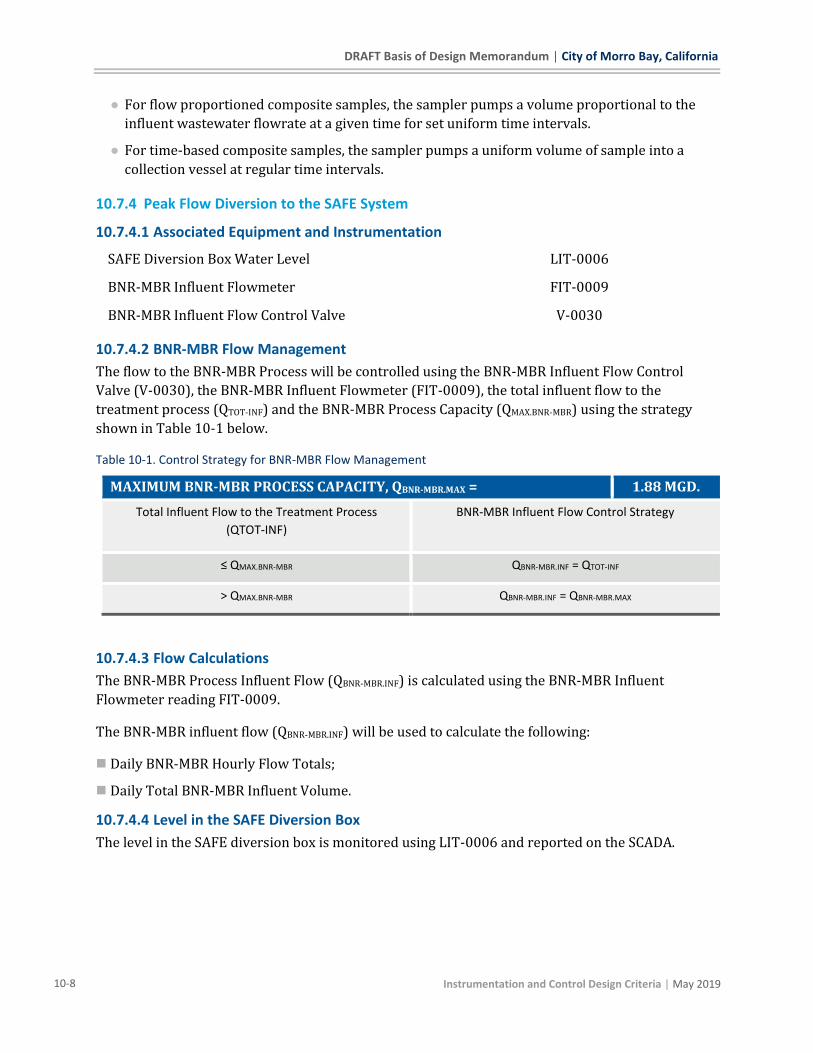
DRAFT Basis of Design Memorandum | City of Morro Bay, California
10-8 Instrumentation and Control Design Criteria | May 2019
● For flow proportioned composite samples, the sampler pumps a volume proportional to the
influent wastewater flowrate at a given time for set uniform time intervals.
● For time-based composite samples, the sampler pumps a uniform volume of sample into a
collection vessel at regular time intervals.
10.7.4 Peak Flow Diversion to the SAFE System
10.7.4.1 Associated Equipment and Instrumentation
SAFE Diversion Box Water Level LIT-0006
BNR-MBR Influent Flowmeter FIT-0009
BNR-MBR Influent Flow Control Valve V-0030
10.7.4.2 BNR-MBR Flow Management
The flow to the BNR-MBR Process will be controlled using the BNR-MBR Influent Flow Control
Valve (V-0030), the BNR-MBR Influent Flowmeter (FIT-0009), the total influent flow to the
treatment process (QTOT-INF) and the BNR-MBR Process Capacity (QMAX.BNR-MBR) using the strategy
shown in Table 10-1 below.
Table 10-1. Control Strategy for BNR-MBR Flow Management
MAXIMUM BNR-MBR PROCESS CAPACITY, QBNR-MBR.MAX = 1.88 MGD.
Total Influent Flow to the Treatment Process
(QTOT-INF)
BNR-MBR Influent Flow Control Strategy
≤ QMAX.BNR-MBR QBNR-MBR.INF = QTOT-INF
> QMAX.BNR-MBR QBNR-MBR.INF = QBNR-MBR.MAX
10.7.4.3 Flow Calculations
The BNR-MBR Process Influent Flow (QBNR-MBR.INF) is calculated using the BNR-MBR Influent
Flowmeter reading FIT-0009.
The BNR-MBR influent flow (QBNR-MBR.INF) will be used to calculate the following:
◼ Daily BNR-MBR Hourly Flow Totals;
◼ Daily Total BNR-MBR Influent Volume.
10.7.4.4 Level in the SAFE Diversion Box
The level in the SAFE diversion box is monitored using LIT-0006 and reported on the SCADA.

City of Morro Bay, California | DRAFT Basis of Design Memorandum
| Instrumentation and Control Design Criteria 10-9
10.7.5 Fine Screening
10.7.5.1 Associated Equipment and Instrumentation
Fine Screen # 1 SCR-0003
Fine Screen # 1 Differential Level Sensor SCR1.LDIT-0003
Fine Screen # 2 SCR-0004
Fine Screen # 2 Differential Level Sensor SCR1.LDIT-0004
Fine Screenings Conveyer CNV-XXXX
10.7.5.2 Fine Screens Operation
Local Control Panels are provided by the Fine Screen System supplier for independent control of
each of the fine screens and associated equipment. Control information provided herein is for
information only and is a general description of operating philosophy. This description is subject to
change to conform to the system suppliers’ standards and typical operating approach.
The fine screens may be operated in manual or automatic mode as described below. Details of the
control are to be determined by the system provider.
◼ Local Manual Mode.: TBD
◼ Remote Manual Mode: Local control panel initiates operation of screen drum,
washer/compactor, and conveyor. Operators manually select which unit(s) operate and leave
them running continuously. Control valve utilizes flow meter to maintain the MBR treatment
flow capacity, maximum flow of 1.88 mgd through the fine screens. The valve is controlled
directly by the Plant PLC and can be remotely or manually set to a position.
◼ Remote Auto Mode: Automatic screen operation is based on differential level and/or time.
● For differential level control, the water level is measured upstream and downstream of each
screen. The basket starts to rotate when a preset differential level is exceeded due to screen
surface blinding. The rotating screen drum lifts the screenings and drops them into the
centrally arranged trough. Screenings removal from the drum is supported by a scraper brush
and a spray nozzle bar. Plant recycled water is supplied by a solenoid valves. In the event
plant recycled water pressure is low a pressure switch generates an alarm. A screw conveyor
in the trough rotates with the drum and transports the screenings through a closed and
inclined pipe. The conveying screw transports, dewaters and compacts the screenings, without
any odor nuisance, and discharges them into the dumpster. Screened wastewater is combined
in a pipeline that discharges to the MBR.
● For timer control, a programmable timer is used to initiate cleaning events. During periods of
low flow the rake may not reach levels high enough to trigger an event. A 24-hour
programmable timer can be set to periodically operate the drum to ensure screenings stay
fresh.

DRAFT Basis of Design Memorandum | City of Morro Bay, California
10-10 Instrumentation and Control Design Criteria | May 2019
10.7.5.2.1 Washer/Compactor
Washer compactor operation is interlocked with the drum screen.
10.7.5.2.2 Conveyor
The conveyor is integrated with the washer compactor. A time delay setting maintains the
conveyor powered for a set time period after the compactor stops running.
10.7.6 BNR System
10.7.6.1 Associated Equipment and Instrumentation
BNR RAS DeOx Mixer MXR-0003
BNR Splitter Box pH AIT-0071
BNR # 1 System
BNR # 1 Anoxic Zone Mixer MXR-0001
BNR # 1 Aerobic Zone 1 Dissolved Oxygen AIR-0068
BNR # 1 Aerobic Zone 1 Air Flow Meter FIT-0067
BNR # 1 Aerobic Zone 1 Air Flow Control Valve V-0046
BNR # 1 Aerobic Zone 2 Dissolved Oxygen AIT-0073
BNR # 1 Aerobic Zone 2 Air Flow Meter FIT-0070
BNR # 1 Aerobic Zone 2 Air Flow Control Valve V-0047
BNR # 1 Aerobic Zone 2 MLSS AIR-0075
BNR # 1 Aerobic Zone 2 Ammonia-N AIT-0076
BNR # 1 Surface Wasting Valve V-XXXX
BNR # 1 MBR Feed Pump P-XXXX
BNR # 1 MBR Feed Pump Flowmeter FIT-XXXX
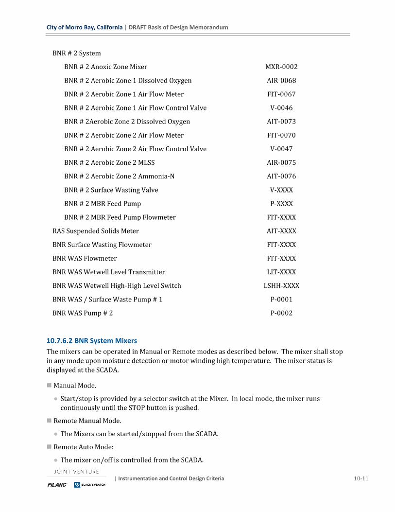
City of Morro Bay, California | DRAFT Basis of Design Memorandum
| Instrumentation and Control Design Criteria 10-11
BNR # 2 System
BNR # 2 Anoxic Zone Mixer MXR-0002
BNR # 2 Aerobic Zone 1 Dissolved Oxygen AIR-0068
BNR # 2 Aerobic Zone 1 Air Flow Meter FIT-0067
BNR # 2 Aerobic Zone 1 Air Flow Control Valve V-0046
BNR # 2Aerobic Zone 2 Dissolved Oxygen AIT-0073
BNR # 2 Aerobic Zone 2 Air Flow Meter FIT-0070
BNR # 2 Aerobic Zone 2 Air Flow Control Valve V-0047
BNR # 2 Aerobic Zone 2 MLSS AIR-0075
BNR # 2 Aerobic Zone 2 Ammonia-N AIT-0076
BNR # 2 Surface Wasting Valve V-XXXX
BNR # 2 MBR Feed Pump P-XXXX
BNR # 2 MBR Feed Pump Flowmeter FIT-XXXX
RAS Suspended Solids Meter AIT-XXXX
BNR Surface Wasting Flowmeter FIT-XXXX
BNR WAS Flowmeter FIT-XXXX
BNR WAS Wetwell Level Transmitter LIT-XXXX
BNR WAS Wetwell High-High Level Switch LSHH-XXXX
BNR WAS / Surface Waste Pump # 1 P-0001
BNR WAS Pump # 2 P-0002
10.7.6.2 BNR System Mixers
The mixers can be operated in Manual or Remote modes as described below. The mixer shall stop
in any mode upon moisture detection or motor winding high temperature. The mixer status is
displayed at the SCADA.
◼ Manual Mode.
● Start/stop is provided by a selector switch at the Mixer. In local mode, the mixer runs
continuously until the STOP button is pushed.
◼ Remote Manual Mode.
● The Mixers can be started/stopped from the SCADA.
◼ Remote Auto Mode:
● The mixer on/off is controlled from the SCADA.

DRAFT Basis of Design Memorandum | City of Morro Bay, California
10-12 Instrumentation and Control Design Criteria | May 2019
● When in in auto mode, the mixer can be controlled using operator adjustable set-points for the
interval between mixer operation and duration of mixer operation.
10.7.6.3 BNR System Supplemental Alkalinity Addition
Alkalinity (sodium hydroxide) is dosed following fine screening based on an operator adjustable pH
target and the measured pH in the BNR splitter box.
◼ Local Manual Mode. Not applicable
◼ Remote Manual Mode: The dosing pump on/off and operator adjustable speed are controlled on
the HMI.
◼ Remote Auto Mode: When in auto mode, process control is used to maintain the pH in the BNR
aerobic zone at an operator adjustable acceptable setpoint.
10.7.6.4 BNR Aeration Control
Aeration Control can be achieved using Local or Remote modes as described below. Local Manual
and Remote Manual modes is primarily designed for troubleshooting and valve evaluation
operations.
◼ Local Manual Mode. In local mode, the valves controlling each aeration grid are operated using
open-close-stop switches mounted on the valves actuators.
◼ Remote Manual Mode: In remote manual mode, the valve position can be controlled from the
SCADA.
◼ Remote Auto Mode: In remote-auto mode, two air flow control modes are available. The aeration
control mode can be selected by the operator from the SCADA. The air flow control valve to each
drop-leg will be controlled based on the operator selected DO control mode.
● Fixed DO control mode
▪ Feedback process control maintains a continuous, uniform DO setpoint in each aerobic zone.
The DO setpoint is operator adjustable at the HMI.
▪ DO Set points for Aerobic Zones 1 and 2 in each BNR System are:
● AX.SWING (i.e., DO = 0) or
● A value in the range of DOAE-MIN and DOAE-MAX, indicated in Table 10-2.
Table 10-2. Min and Max Aerobic Zone DO Set Points in Fixed DO Control Mode
Min Operator Selectable DO Set Point DOFDO.AE-MIN 0.2 mg/L
Max. Operator Selectable DO Set Point DOFDO.AE-MAX 1.5 mg/L
▪ When AX.SWING mode operation is selected (i.e., DO Set point = 0). The aeration is turned on
intermittently based on the operator adjustable timer setpoints indicated in Table 10-3. In
this mode, the air flow will be the minimum air flowrate.
Table 10-3. Operator Adjustable Intermittent Aeration in AX.SWING Mode
Interval between aeration events TAIR-BUMP.INT 30 – 360 min
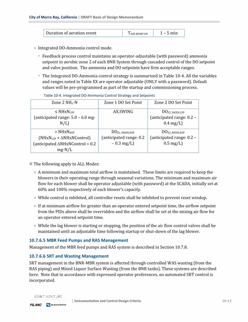
City of Morro Bay, California | DRAFT Basis of Design Memorandum
| Instrumentation and Control Design Criteria 10-13
Duration of aeration event TAIR-BUMP.ON 1 – 5 min
● Integrated DO-Ammonia control mode.
▪ Feedback process control maintains an operator-adjustable (with password) ammonia
setpoint in aerobic zone 2 of each BNR System through cascaded control of the DO setpoint
and valve position. The ammonia and DO setpoints have firm acceptable ranges.
▪ The Integrated DO-Ammonia control strategy is summarized in Table 10-4. All the variables
and ranges noted in Table XX are operator adjustable (ONLY with a password). Default
values will be pre-programmed as part of the startup and commissioning process.
Table 10-4. Integrated DO-Ammonia Control Strategy and Setpoints
Zone 2 NHx-N Zone 1 DO Set Point Zone 2 DO Set Point
≤ NHxNLSP
(anticipated range: 5.0 – 6.0 mg-
N/L)
AX.SWING DOZ2_NHXN.LSP
(anticipated range: 0.2 –
0.4 mg/L)
> NHxNHSP
(NHxNLSP + NHxNControl)
(anticipated NHxNControl = 0.2
mg-N/L
DOZ1_NHXN.HSP
(anticipated range: 0.2
– 0.3 mg/L)
DOZ2_NHXN.HSP
(anticipated range: 0.2 –
0.5 mg/L)
◼ The following apply to ALL Modes:
● A minimum and maximum total airflow is maintained. These limits are required to keep the
blowers in their operating range through seasonal variations. The minimum and maximum air
flow for each blower shall be operator adjustable (with password) at the SCADA, initially set at
60% and 100% respectively of each blower’s capacity.
● While control is inhibited, all controller resets shall be inhibited to prevent reset windup.
● If at minimum airflow for greater than an operator entered setpoint time, the airflow setpoint
from the PIDs above shall be overridden and the airflow shall be set at the mixing air flow for
an operator entered setpoint time.
● While the lag blower is starting or stopping, the position of the air flow control valves shall be
maintained until an adjustable time following startup or shut-down of the lag blower.
10.7.6.5 MBR Feed Pumps and RAS Management
Management of the MBR feed pumps and RAS system is described in Section 10.7.8.
10.7.6.6 SRT and Wasting Management
SRT management in the BNR-MBR system is affected through controlled WAS wasting (from the
RAS piping) and Mixed Liquor Surface Wasting (from the BNR tanks). These systems are described
here. Note that in accordance with expressed operator preferences, no automated SRT control is
incorporated.
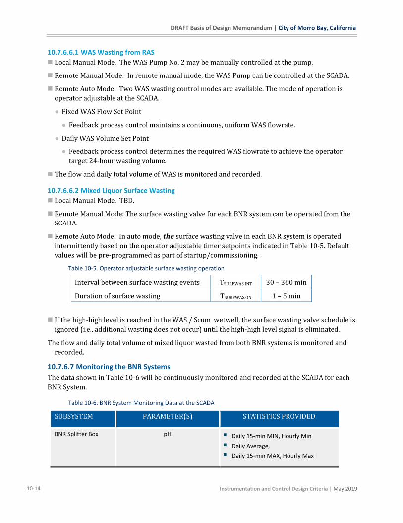
DRAFT Basis of Design Memorandum | City of Morro Bay, California
10-14 Instrumentation and Control Design Criteria | May 2019
10.7.6.6.1 WAS Wasting from RAS
◼ Local Manual Mode. The WAS Pump No. 2 may be manually controlled at the pump.
◼ Remote Manual Mode: In remote manual mode, the WAS Pump can be controlled at the SCADA.
◼ Remote Auto Mode: Two WAS wasting control modes are available. The mode of operation is
operator adjustable at the SCADA.
● Fixed WAS Flow Set Point
● Feedback process control maintains a continuous, uniform WAS flowrate.
● Daily WAS Volume Set Point
● Feedback process control determines the required WAS flowrate to achieve the operator
target 24-hour wasting volume.
◼ The flow and daily total volume of WAS is monitored and recorded.
10.7.6.6.2 Mixed Liquor Surface Wasting
◼ Local Manual Mode. TBD.
◼ Remote Manual Mode: The surface wasting valve for each BNR system can be operated from the
SCADA.
◼ Remote Auto Mode: In auto mode, the surface wasting valve in each BNR system is operated
intermittently based on the operator adjustable timer setpoints indicated in Table 10-5. Default
values will be pre-programmed as part of startup/commissioning.
Table 10-5. Operator adjustable surface wasting operation
Interval between surface wasting events TSURFWAS.INT 30 – 360 min
Duration of surface wasting TSURFWAS.ON 1 – 5 min
◼ If the high-high level is reached in the WAS / Scum wetwell, the surface wasting valve schedule is
ignored (i.e., additional wasting does not occur) until the high-high level signal is eliminated.
The flow and daily total volume of mixed liquor wasted from both BNR systems is monitored and
recorded.
10.7.6.7 Monitoring the BNR Systems
The data shown in Table 10-6 will be continuously monitored and recorded at the SCADA for each
BNR System.
Table 10-6. BNR System Monitoring Data at the SCADA
SUBSYSTEM PARAMETER(S) STATISTICS PROVIDED
BNR Splitter Box pH ▪ Daily 15-min MIN, Hourly Min
▪ Daily Average,
▪ Daily 15-min MAX, Hourly Max
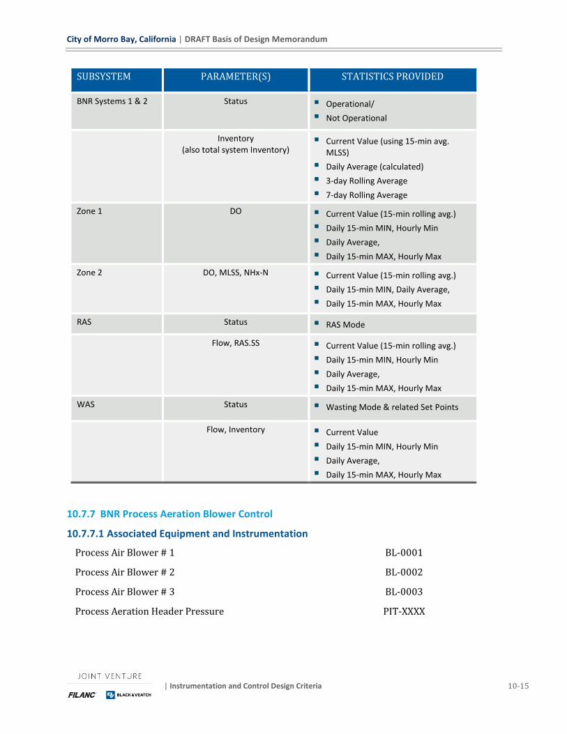
City of Morro Bay, California | DRAFT Basis of Design Memorandum
| Instrumentation and Control Design Criteria 10-15
SUBSYSTEM PARAMETER(S) STATISTICS PROVIDED
BNR Systems 1 & 2 Status ▪ Operational/
▪ Not Operational
Inventory (also total system Inventory)
▪ Current Value (using 15-min avg. MLSS)
▪ Daily Average (calculated)
▪ 3-day Rolling Average
▪ 7-day Rolling Average
Zone 1 DO ▪ Current Value (15-min rolling avg.)
▪ Daily 15-min MIN, Hourly Min
▪ Daily Average,
▪ Daily 15-min MAX, Hourly Max
Zone 2 DO, MLSS, NHx-N ▪ Current Value (15-min rolling avg.)
▪ Daily 15-min MIN, Daily Average,
▪ Daily 15-min MAX, Hourly Max
RAS Status ▪ RAS Mode
Flow, RAS.SS ▪ Current Value (15-min rolling avg.)
▪ Daily 15-min MIN, Hourly Min
▪ Daily Average,
▪ Daily 15-min MAX, Hourly Max
WAS Status ▪ Wasting Mode & related Set Points
Flow, Inventory ▪ Current Value
▪ Daily 15-min MIN, Hourly Min
▪ Daily Average,
▪ Daily 15-min MAX, Hourly Max
10.7.7 BNR Process Aeration Blower Control
10.7.7.1 Associated Equipment and Instrumentation
Process Air Blower # 1 BL-0001
Process Air Blower # 2 BL-0002
Process Air Blower # 3 BL-0003
Process Aeration Header Pressure PIT-XXXX
DRAFT Basis of Design Memorandum | City of Morro Bay, California
10-16 Instrumentation and Control Design Criteria | May 2019
10.7.7.2 Blower Control
In all control modes, the blower shall be hardwired interlocked to not start against a closed
discharge valve and shall shutdown on high temperature or high discharge pressure.
◼ Local Manual Mode.
● The blower on/off is controlled from the blower LCP.
● Once the START button is pushed, the blower shall run continuously until the STOP button is
pushed.
● The blower speed is adjustable from the VFD.
◼ Remote Manual Mode.
● The blower ON/OFF can be controlled from the SCADA using operator manual commands.
● Blower speed shall be adjusted based on the speed input entered at the SCADA.
◼ Remote Auto Mode.
● The blower is controlled by a PI type control function to maintain a pressure control setpoint
in the process aeration header. The pressure set point will be operator adjustable (with a
password). A default value will be pre-programmed during startup/commissioning.
● A most open valve (MOV) algorithm is employed that selects the most open valve which is used
to control the adjustment (see items 4 and 5 below) of the process aeration header pressure
setpoint (see item 1 below).
1. The lead blower runs continuously with the speed controlled by a pressure controller, to maintain a pressure setpoint.
2. As demand increases and total air flow demand remains at the maximum for an operator-adjustable time period, a lag blower starts. Once running, the lead and lag blowers modulate together to maintain the setpoint discharge header pressure.
3. The blower speed modulates to control header pressure to maintain the setpoint. When the total air flow demand falls below the capacity of the lead blower for an adjustable period of time, the lag blower shutdown is initiated. Once the lag blower has shut down, the speed of the lead blower is controlled to maintain the setpoint pressure.
4. If the position of the most open basin air flow control valve exceeds an operator entered maximum position, the setpoint header pressure increases 0.1 PSI. This requires the air flow control valve to travel toward the closed position to maintain the setpoint airflow. The system stabilizes for an operator adjustable time period. If the valve remains above the maximum setpoint position, another increase of 0.1 PSI to the air pressure setpoint is made.
5. If the position of the most open air flow control valve becomes less than the operator entered minimum position, the setpoint header pressure decreases 0.1 PSI. This requires the air flow control valve to travel toward the open position to maintain the setpoint airflow. The system stabilizes for an operator adjustable time period. If the valve remains at a position less than the minimum position, another decrease of 0.1 PSI to the air pressure setpoint is made.
City of Morro Bay, California | DRAFT Basis of Design Memorandum
| Instrumentation and Control Design Criteria 10-17
10.7.8 MBR System
10.7.8.1 Associated Equipment and Instrumentation
BNR # 1 MBR Feed Pump P-XXXX
BNR # 2 MBR Feed Pump P-XXXX
MBR Basin # 1
MBR Basin # 1 Isolation Valve V-XXXX
MBR Basin # 1 Drain Isolation Valve V-XXXX
MBR Basin # 1 Level LIT-XXXX
MBR Basin # 1 Low-Low Level Switch LSLL-XXXX
MBR Basin # 1 High-High Level Switch LSHH-XXXX
MBR Basin # 1 Sodium Hypochlorite Isolation Valve V-XXXX
MBR Basin # 1 Citric Acid Isolation Valve V-XXXX
MBR Basin # 1 Scour Air Isolation Valve V-0067
MBR Basin # 1 Filtrate Pump P-0003
MBR Basin # 1 Filtrate Flowmeter FIT-0097
MBR Basin # 1 Filtrate Turbidity AIT-0098
MBR Basin # 1 RAS Channel Level LIT-XXXX
MBR Basin # 1 RAS Channel Level Control Valve V-XXXX
MBR Basin # 1 RAS Flowmeter FIT-XXXX
MBR Basin # 2
MBR Basin # 2 Isolation Valve V-XXXX
MBR Basin # 2 Drain Isolation Valve V-XXXX
MBR Basin # 2 Level LIT-XXXX
MBR Basin # 2 Low-Low Level Switch LSLL-XXXX
MBR Basin # 2 High-High Level Switch LSHH-XXXX
MBR Basin # 2 Sodium Hypochlorite Isolation Valve V-XXXX
DRAFT Basis of Design Memorandum | City of Morro Bay, California
10-18 Instrumentation and Control Design Criteria | May 2019
MBR Basin # 2 Citric Acid Isolation Valve V-XXXX
MBR Basin # 2 Scour Air Isolation Valve V-0067
MBR Basin # 2 Filtrate Pump P-0003
MBR Basin # 2 Filtrate Flowmeter FIT-0097
MBR Basin # 2 Filtrate Turbidity AIT-0098
MBR Basin # 2 RAS Channel Level LIT-XXXX
MBR Basin # 2 RAS Channel Level Control Valve V-XXXX
MBR Basin # 2 RAS Flowmeter FIT-XXXX
BNR-MBR System Drain Pump P-0008
BNR-MBR System Drain Pump Flowmeter FIT-0126
MBR Filtrate Ammonia-Nitrogen AIT-0120
MBR Filtrate Turbidity AIT-0121
MBR System Air Scour Blower # 1 BL-0001
MBR System Air Scour Blower # 2 BL-0002
MBR System Air Scour Flowmeter FIT-0033
MBR System Air Scour Header Pressure PIT-0034
10.7.8.2 MBR System Control Overview
The MBR System will be managed by the MBR System Suppliers standard controls and logic.
Control information provided herein is for information only and is a general description of the
operating strategy of the system. This description is subject to change to conform to the MBR
system suppliers’ standards and typical operating approach. The MBR System Controls will manage
the following sub-systems:
▪ MBR Basin Operation Management;
▪ MBR Feed Pumps;
▪ MBR Filtrate Pumps;
▪ MBR Air Scour; and
▪ MBR Cleaning (maintenance and recovery) Operations.
10.7.8.3 MBR System Basin Operation Management
The number of MBR Basins in Operation will be determined based on the following inputs:

City of Morro Bay, California | DRAFT Basis of Design Memorandum
| Instrumentation and Control Design Criteria 10-19
▪ BNR-MBR System influent flow which is measured using FIT-0009 (c.f., Section 10.7.4
above);
▪ The operational limits placed on the Membrane Cassettes by the Membrane System
Supplier (e.g., Transmembrane Pressure, Operating Flux). This is determined and set by the
Membrane System Supplier;
▪ Mechanical and System constraints of equipment (e.g., minimum pump flowrates).
An overview of the MBR Basin Operation Management strategy applicable to Morro Bay WRF is
shown in Figure 10-1.
Figure 10-1. Overview of MBR System Basin Operation Management
10.7.8.4 MBR Feed Pumps Control
MBR Feed Pumps can be operated in Local and Remote modes as described below. Local and
Remote-Manual modes are primarily for equipment verification and testing. The normal control
mode is Remote-Auto mode managed by the MBR System PLC.
◼ Local Manual Mode.
● The MBR Feed Pump can be Started and Stopped using the Local Control Station in the field.
● The pump speed is managed from the VFD.
No. of MBR Trains Currently Operating?
1
2
Q results in performance within acceptable range?
Y
N
Bring Next MBR Train Online
Maintain 1 TrainAdjust flux based on QBNR-IN & MCT level
• High Flux check• TMP• Train availability,
etc.
Q results in performance within acceptable range?
N
YMaintain 2 trains
Put 1 MBR Train in Standby
• Pump turndown• Min flux (velocity, etc.)• Train availability, etc.
Need more mem.SA?
Y
NReduce 1 train to min flow/flux

DRAFT Basis of Design Memorandum | City of Morro Bay, California
10-20 Instrumentation and Control Design Criteria | May 2019
● The pump runs continuously until the STOP button is pushed or hard-interlocks result in the
pump being stopped (e.g., low level in the MBR Feed Channel).
◼ Remote Manual Mode:
● In remote manual mode, the pump operation and speed are controlled from the SCADA.
◼ Remote Auto Mode:
● The MBR Feed Pumps are controlled to maintain a target level flow into each MBR basin and
trimmed based on the level in the MBR Tanks.
10.7.8.5 MBR Filtrate Pumps Control
MBR Filtrate Pumps can be operated in Local and Remote modes as described below. Local and
Remote-Manual modes are primarily for equipment verification and testing. The normal control
mode is Remote-Auto mode managed by the MBR System PLC.
◼ Local Manual Mode.
● The MBR Filtrate Pump can be started and stopped using the Local Control Station in the field.
● The pump speed is managed from the VFD.
● The pump runs continuously until the STOP button is pushed or hard-interlocks result in the
pump being stopped (e.g., low level in the MBR Basin).
◼ Remote Manual Mode:
● In remote manual mode, the pump operation (ON/OFF and Direction) and speed are controlled
from the SCADA.
◼ Remote Auto Mode:
● In Remote-Auto mode, the total filtrate flow is determined based on the BNR-MBR System
influent flow which is measured using FIT-0009 (c.f., Section 10.7.4 above) using Equation (3).
● The Filtrate to Influent Factor (FtoI_Factor) shown in Equation (3) is an operator adjustable
(with password) flow correction factor (0.00 to 1.00, typical value in the range of 0.98 – 1.00)
which allows the operations staff to set a target flow relative to the flow into the BNR-MBR
system. The initial and typical value for this factor will be pre-programmed during
startup/commissioning.
● The Filtrate Flow per MBR basin in operation is calculated as shown in Equation (4).
𝑇𝑜𝑡𝑎𝑙 𝑀𝐵𝑅 𝐹𝑖𝑙𝑡𝑟𝑎𝑡𝑒 𝐹𝑙𝑜𝑤 𝑆𝑒𝑡 𝑃𝑜𝑖𝑛𝑡, 𝑄𝑀𝐵𝑅.𝐹𝐼𝐿𝑇−𝑇𝑂𝑇 = 𝑄𝐹𝐼𝑇−009 ∗ 𝐹𝑡𝑜𝐼_𝐹𝑎𝑐𝑡𝑜𝑟 (3)
𝑀𝐵𝑅 𝐵𝑎𝑠𝑖𝑛 𝐹𝑖𝑙𝑡𝑟𝑎𝑡𝑒 𝐹𝑙𝑜𝑤 𝑆𝑒𝑡 𝑃𝑜𝑖𝑛𝑡, 𝑄𝑀𝐵𝑅.𝐹𝐼𝐿𝑇−𝐵𝐴𝑆𝐼𝑁 =𝑄𝑀𝐵𝑅.𝐹𝐼𝐿𝑇−𝑇𝑂𝑇
𝑁𝑀𝐵𝑅−𝐵𝐴𝑆𝐼𝑁𝑆 (4)
City of Morro Bay, California | DRAFT Basis of Design Memorandum
| Instrumentation and Control Design Criteria 10-21
10.7.8.6 MBR Air Scour
MBR Air Scour Blowers can be operated in Local and Remote modes as described below. Local and
Remote-Manual modes are primarily for equipment verification and testing. The normal control
mode is Remote-Auto mode managed by the MBR System PLC.
◼ Local Mode. The electrically controlled wasting valve may be opened using the switch located on
the actuator and the blowers are operated at the Blower LCP.
◼ Remote Manual Mode:
● In remote manual mode, the air scour valves and blower can be operated from the SCADA.
◼ Remote Auto Mode:
● In Remote-Auto mode (which is the typical mode of operation) – the MBR Air Scour Function is
managed by the MBR System Supplier based on the Suppliers’ Specific scouring algorithm.
10.7.8.7 Membrane Cleaning System
MBR Cleaning cycles are manually initiated by the operator from the SCADA and controlled by the
MBR System control
10.7.8.8 RAS Channel Level Control
The sludge level in the MBR RAS channel is managed at a pre-programmed level to minimize the
drop over the RAS Weir from the Membrane Basins.
The RAS Flow from each basin is monitored and recorded on the SCADA.
10.7.9 Outfall Pumping and Disinfection
10.7.9.1 Associated Equipment and Instrumentation
Outfall Balancing Tank Level LIT-0002
Outfall Balancing Tank High Level LSH-XXXX
Outfall Balancing Tank High-High Level LSHH-XXXX
Outfall Pump # 1 P-0001
Outfall Pump # 2 P-0002
Outfall Pump # 3 P-0003
Outfall Pump #4 P-0004
Outfall Pumping System Flow FIT-0007
Ocean Outfall Residual Chlorine AIT-0008
Sodium Hypochlorite Metering Pump # 1
(for Ocean Outfall Disinfection) P-XXXX
Sodium Hypochlorite Metering Pump # 2
(for RO Concentrate Disinfection) P-XXXX
Sodium Bisulfite Metering Pump P-XXXX

DRAFT Basis of Design Memorandum | City of Morro Bay, California
10-22 Instrumentation and Control Design Criteria | May 2019
10.7.9.2 Outfall Pumps Operation
The Outfall Pumps can be operated in Local Manual or Remote modes as described below. The
pumps shall stop in any mode upon moisture detection or motor winding high temperature or
LOW-LOW level in the Outfall Balancing Tank. The pump status is displayed at the SCADA.
◼ Local Manual Mode.
● Start/stop is provided by a selector switch at the Pumps.
● In local mode, the pump runs continuously until the STOP button is pushed.
◼ Remote Manual Mode.
● The Outfall pumps can be operated from the SCADA.
◼ Remote Auto Mode:
● The Outfall Pumps are controlled based on the level in the Outfall Balancing Tank.
● In the event of a high-high level, the pumps will be operated continuously until the low-level
set point is achieved.
10.7.9.3 Flow Calculations
The Morro Bay Wastewater Ocean Discharge Effluent Flow is calculated as the sum of the flows
measured using the Outfall Pumping System Flowmeter (FIT-0007) and the RO Concentrate
Flowmeters (c.f., Section 10.7.11) The Ocean Discharge Effluent Flow (QOC.DISCH) will be used to
calculate the following:
▪ Daily Hourly Ocean Discharge Flows; and
▪ Daily Total Ocean Discharge Volume.
10.7.9.4 Pumped Flow Disinfection
The pumped flow is disinfected using sodium hypochlorite fed using the sodium hypochlorite
dosing pumps. The pumps can be operated in Local and Remote modes as noted below.
◼ Local Manual Mode.
● Start/stop is provided by a selector switch at the Pump.
● In local mode, the pump runs continuously until the STOP button is pushed.
◼ Remote Manual Mode.
● The sodium hypochlorite feed pump can be operated from the SCADA.
◼ Remote Auto Mode:
● The sodium hypochlorite pump for disinfection of the pumped flow to the ocean outfall is
controlled to achieve a target operator adjustable (with password) sodium hypochlorite dose
(DNaOCl_POutfall).
City of Morro Bay, California | DRAFT Basis of Design Memorandum
| Instrumentation and Control Design Criteria 10-23
● The sodium hypochlorite feed flow is calculated as shown in Equation 5. The Unit/Formula
correction factors integrate the sodium hypochlorite solution strength (CNaOCl_STOCK) and unit
conversion factors to get a calculated target NaOCl in gallons per minute.
𝑁𝑎𝑂𝐶𝑙 𝐹𝑙𝑜𝑤 𝑓𝑜𝑟 𝑝𝑢𝑚𝑝𝑒𝑑 𝑜𝑢𝑡𝑓𝑎𝑙𝑙 𝑓𝑙𝑜𝑤, 𝑄𝑁𝑎𝑂𝐶𝑙,𝑃_𝑂𝑢𝑡𝑓𝑎𝑙𝑙 = 𝑄𝐹𝐼𝑇−007
∗ 𝐷𝑁𝑎𝑂𝐶𝑙_𝑃𝑂𝑢𝑡𝑓𝑎𝑙𝑙 ∗ 𝑈𝑛𝑖𝑡/𝐹𝑜𝑟𝑚𝑢𝑙𝑎 𝐶𝑜𝑟𝑟𝑒𝑐𝑡𝑖𝑜𝑛 𝐹𝑎𝑐𝑡𝑜𝑟𝑠 (5)
10.7.9.5 RO Concentrate Flow Disinfection
The RO concentrate flow is disinfected using sodium hypochlorite dosing pumps. The pumps can be
operated in Local and Remote modes as noted below.
◼ Local Manual Mode.
● Start/stop is provided by a selector switch at the Pump.
● In local mode, the pump runs continuously until the STOP button is pushed.
◼ Remote Manual Mode.
● The sodium hypochlorite feed pump can be operated from the SCADA.
◼ Remote Auto Mode:
● The sodium hypochlorite pumps are controlled to achieve a target operator adjustable (with
password) sodium hypochlorite dose (DNaOCl_ROConc).
● The sodium hypochlorite feed flow is calculated as shown in Equation 6. The Unit/Formula
correction factors integrate the sodium hypochlorite solution strength (CNaOCl_STOCK) and unit
conversion factors to get a calculated target NaOCl in gallons per minute.
𝑁𝑎𝑂𝐶𝑙 𝐹𝑙𝑜𝑤 𝑓𝑜𝑟 𝑝𝑢𝑚𝑝𝑒𝑑 𝑜𝑢𝑡𝑓𝑎𝑙𝑙 𝑓𝑙𝑜𝑤, 𝑄𝑁𝑎𝑂𝐶𝑙,𝑅𝑂𝐶𝑜𝑛𝑐
= (𝑄𝐹𝐼𝑇−0081 + 𝑄𝐹𝐼𝑇−0091 + 𝑄𝐹𝐼𝑇−0101) ∗ 𝐷𝑁𝑎𝑂𝐶𝑙_𝑅𝑂𝐶𝑜𝑛𝑐
∗ 𝑈𝑛𝑖𝑡/𝐹𝑜𝑟𝑚𝑢𝑙𝑎 𝐶𝑜𝑟𝑟𝑒𝑐𝑡𝑖𝑜𝑛 𝐹𝑎𝑐𝑡𝑜𝑟𝑠
(6)
10.7.9.6 Ocean Outfall Flow Dechlorination
The flow directed to the ocean outfall is dechlorinated using sodium bisulfite fed using the sodium
bisulfite dosing pumps. The pumps can be operated in Local and Remote modes as noted below.
◼ Local Manual Mode.
● Start/stop is provided by a selector switch at the Pump.
● In local mode, the pump runs continuously until the STOP button is pushed.
◼ Remote Manual Mode.
● The sodium bisulfite feed pump can be operated from the SCADA.
◼ Remote Auto Mode:
DRAFT Basis of Design Memorandum | City of Morro Bay, California
10-24 Instrumentation and Control Design Criteria | May 2019
● The sodium bisulfite pumps are controlled using a feedback control strategy based on a target
operator adjustable (with password) bisulfite to residual chlorine ratio (RNaBis_ResidCl) and the
chlorine residual measured using AIT-0008.
● The sodium bisulfite feed flow is calculated as shown in Equation 7. The Unit/Formula
correction factors integrate the sodium bisulfite solution strength (CNaBis_STOCK) and unit
conversion factors to get a calculated target NaHSO4 in gallons per minute.
𝑁𝑎𝐻𝑆𝑂4 𝐹𝑙𝑜𝑤 𝑓𝑜𝑟 𝑝𝑢𝑚𝑝𝑒𝑑 𝑜𝑢𝑡𝑓𝑎𝑙𝑙 𝑓𝑙𝑜𝑤, 𝑄𝑁𝑎𝐵𝑖𝑠
= (𝑄𝐹𝐼𝑇−0007 + 𝑄𝐹𝐼𝑇−0081 + 𝑄𝐹𝐼𝑇−0091 + 𝑄𝐹𝐼𝑇−0101)
∗ 𝐶𝐶𝑙−𝐴𝐼𝑇0008 ∗ 𝑅𝑁𝑎𝐵𝑖𝑠_𝑅𝑒𝑠𝑖𝑑𝐶𝑙 ∗ 𝑈𝑛𝑖𝑡/𝐹𝑜𝑟𝑚𝑢𝑙𝑎 𝐶𝑜𝑟𝑟𝑒𝑐𝑡𝑖𝑜𝑛 𝐹𝑎𝑐𝑡𝑜𝑟𝑠
(7)
10.7.10 Effluent Composite Sampler
The composite sampler samples and chills the water used in routine analyses.
10.7.10.1 Associated Equipment and Instrumentation
Effluent Composite Sampler SMPLR-XXXX
10.7.10.2 Sampling Strategies
◼ Local Manual Mode.
◼ Remote Manual Mode: In remote manual mode, the operator may use the sampler SCADA to turn
on/off the sampling pump.
◼ Remote Auto Mode: Automatic sampling operation is based on flow-proportioned composite
sampling or time-based composite sampling.
● For flow proportioned composite samples, the sampler pumps a volume proportional to the
influent wastewater flowrate at a given time for set uniform time intervals.
● For time-based composite samples, the sampler pumps a uniform volume of sample into a
collection vessel at regular time intervals.
10.7.11 RO System
10.7.11.1 Associated Equipment and Instrumentation
RO Feed Tank # 1 Level LIT-0132
RO Feed Tank # 1 Low-Low Level LSLL-0135
RO Feed Tank # 1 High-High Level LSHH-0134
RO Feed Tank # 2 Level LIT-0136
RO Feed Tank # 2 Low-Low Level LSLL-0139
RO Feed Tank # 2 High-High Level LSHH-0138
RO Feed Conductivity AIT-0012
RO Feed Turbidity AIT-0014

City of Morro Bay, California | DRAFT Basis of Design Memorandum
| Instrumentation and Control Design Criteria 10-25
RO Feed Oxidation-Reduction Potential AIT-0016
RO Feed Free Chlorine AIT-0018
RO Feed Monochloramine / Ammonia AIT-0020
RO Feed pH AIT-0022
RO System # 1
RO Feed Pump # 1 P-0005
RO Cartridge Filter # 1 FLC-0001
RO Unit # 1 Feed Valve V-0086
RO Unit # 1 Booster Pump P-0008
RO Unit # 1 Stage 1 Conductivity AIT-0045
RO Unit # 1 Stage 2 Conductivity AIT-0052
RO Unit # 1 Permeate Conductivity AIT-0078
RO Unit # 1 Permeate Flow FIT-0077
RO Unit # 1 Permeate to AOP Valve V-0190
RO Unit # 1 Permeate to Outfall Valve V-0189
RO Unit # 1 Concentrate Flow FIT-0081
RO Unit # 1 Concentrate Conductivity AIT-0082
RO System # 2
RO Feed Pump # 2 P-0006
RO Cartridge Filter # 2 FLC-0002
RO Unit # 2 Feed Valve V-0117
RO Unit # 2 Booster Pump P-0009
RO Unit # 2 Stage 1 Conductivity AIT-0056
RO Unit # 2 Stage 2 Conductivity AIT-0062
RO Unit # 2 Permeate Conductivity AIT-0088
RO Unit # 2 Permeate Flow FIT-0087
RO Unit # 2 Permeate to AOP Valve V-0216
RO Unit # 2 Permeate to Outfall Valve V-0189
RO Unit # 2 Concentrate Flow FIT-0091
RO Unit # 2 Concentrate Conductivity AIT-0092
DRAFT Basis of Design Memorandum | City of Morro Bay, California
10-26 Instrumentation and Control Design Criteria | May 2019
RO System # 3
RO Feed Pump # 3 P-0007
RO Cartridge Filter # 3 FLC-0003
RO Unit # 3 Feed Valve V-00148
RO Unit # 3 Booster Pump P-0010
RO Unit # 3 Stage 1 Conductivity AIT-0066
RO Unit # 3 Stage 2 Conductivity AIT-0072
RO Unit # 3 Permeate Conductivity AIT-0098
RO Unit # 3 Permeate Flow FIT-0097
RO Unit # 3 Permeate to AOP Valve V-0240
RO Unit # 3 Permeate to Outfall Valve V-0189
RO Unit # 3 Concentrate Flow FIT-0101
RO Unit # 3 Concentrate Conductivity AIT-0102
10.7.11.2 RO System Control Overview
The RO System will be controlled by the RO System Suppliers standard controls and logic. Control
information provided herein is for information only and is a general description of the operating
strategy of the system. This description is subject to change to conform to the RO system suppliers’
standards and typical operating approach. The RO System Controls will manage the following sub-
systems:
◼ RO Feed Tanks System;
◼ RO High Pressure Feed Pumps;
◼ Cartridge Filters;
◼ RO Units;
◼ CIP Makeup and Neutralization Systems;
◼ RO Flush System
10.7.11.3 RO Feed System
The MBR permeate pumps discharge to the two RO feed tanks. The tank levels are measured,
displayed locally and transmitted to PLC. The tank has switches that are used to activate the High-
High (HH) and Low-Low (LL) Levels. RO feed pumps will convey water from the RO feed tanks
through the cartridge filters and through the RO membranes. RO pretreatment chemicals
including: sodium hypochlorite and antiscalant are added to the RO feed supply line. A locally
mounted flow meter measures, displays and transmits to PLC. After chemical has been added a
sample pump pulls a portion of the flow from the feed line and discharges it to the RO Feed
City of Morro Bay, California | DRAFT Basis of Design Memorandum
| Instrumentation and Control Design Criteria 10-27
Analytical Panel where conductivity, turbidity, ORP, free chlorine, pH, ammonia, and
monochloramine are measured, displayed and transmitted to the PLC.
10.7.11.4 RO Unit Operation
10.7.11.4.1 Number/Selection of RO Units in Operation
The RO system consists of three RO Units which are independently operated and controlled. RO
Units will be started and stopped based on preset trigger levels in the RO feed tanks. At a given
time, 0, 1, 2, or 3 RO units will be called into service operation. RO units will be called into and out
of service based on the following conditions.
◼ @ HH Tank Level (W ft) all three RO units will operate.
◼ @ Midway Tank Level (X ft) two RO units will operate.
◼ @ Low Tank Level (Y ft) one RO unit will operate
◼ @ LL Tank Level (Z) zero RO units will operate
The RO unit with lowest runtime will be called into service when required.
10.7.11.4.2 RO Feed Pump Control
The RO high pressure pumps will be used to convey water from the RO feed tanks through the
cartridge filter to the RO units. The RO high pressure feed pumps (with VFD) shall be controlled to
achieve a permeate flow set point of that RO unit (sum of the permeate flow from each stage of the
RO unit). One feed pump is dedicated to Stage 1 of each RO unit. The RO units shall automatically be
brought into and out of service as described above. Concentrate control valves shall be controlled to
achieve a set flow rate based on the target recovery of that unit. A booster pump is used to increase
second stage feed flow to balance the flux between first stage and second stage by controlling the
permeate flow of the first stage. Pressure is measured on the RO permeate (ROP) and RO
concentrate (ROC). Conductivity is measured on the ROP of each stage, displayed locally and
transmitted to PLC. The ROP flow rate is measured locally displayed and transmitted to PLC.
Pressure is monitored locally, displayed and transmitted to PLC.
ROP pressure is monitored, displayed locally and transmitted to the PLC. In the event of high
pressure, a pressure switch generates an alarm at the PLC and the RO system is shut down. A flow
meter measures, displays and transmits the RO Unit ROP to PLC. ROP outlet piping three locations.
During a normal operation ROP is directed to the UV system for disinfection/advanced oxidation
through a flow control valve. Valve controls are set locally. In Local valve position is set using the
Open and Close selector switch; in Remote control is passed to the PLC that controls the RO System.
Flow not directed to the UV system is a split between the Outfall Pump Station (OPS) and the RO CIP
System. Note that RO train ROP to the outfall is combined in a single line to the OPS.
10.7.11.4.3 RO Sequencing
10.7.11.4.3.1 Pre-Operative Feed Water RO Unit Bypass
A pre-operative bypass shall be executed when the first unit is brought into service with all other
units remaining offline. During this procedure flow shall bypass all the RO units, allowing feed

DRAFT Basis of Design Memorandum | City of Morro Bay, California
10-28 Instrumentation and Control Design Criteria | May 2019
water parameters to stabilize at a set point and chemical flows to stabilize before feed water is
admitted to the membranes.
10.7.11.4.3.2 Post-Operative Feed Water RO Unit Flush
An automatic post-operative feed water flush cycle which shall be initiated automatically upon
shutdown of the plant, unless the Operator selected no feed flush option. The purpose of the post-
operative feed water flush cycle is to ensure that concentrate is flushed from the membranes to
prevent fouling of the membranes, corrosion and scale accumulation.
10.7.11.4.3.3 Post-Operative Permeate Water RO Unit Flush
The membrane flush system is used to remove salt and scale buildup at the RO membrane surface
that normally occurs during the membrane permeation process upon normal shutdown of the RO
train. By flushing the membranes with RO permeate, any concentrated salts are washed from the
membranes, minimizing possible scaling during system shutdown time periods. The flushing
system is automatically energized during the normal RO system shutdown cycle or can be manually
started by the facility operator.
10.7.11.4.4 RO Flushing System
A portion of the ROP is directed to the RO Flush Tank for use in flushing the membranes. An
automatic valve is located on the flushing feed to admit permeate when the tank is low. Valve open
and close can be set at the PLC.
The tank level is measured, displayed locally and transmitted to PLC. The tank has switches that are
used to activate the High-High and Low-Low Levels.
The tank supplies the RO flush pumps which discharge the ROP through the cartridge filer and then
through the RO system. . Pump controls are set locally. In the On position the pump runs
continuously; in the Off position the pumps does not run. Pump duty selection (duty, standby, or
out of service) and pump start and stop levels are set from the configuration screen. In the event
the Duty pump fails the Standby pump runs. When a pump is selected as out of service the pump is
taken out of the control loop. The Duty pump starts at a preset low tank level and stops when the
high level setpoint is reached. Discharge pressure is shown locally on the pump discharge. Pressure
is monitored on the cartridge filter supply and is displayed locally and transmitted to PLC.
10.7.11.4.5 RO CIP Makeup Tank
RO CIP solution is formulated in the RO CIP Makeup Tank. High pH and low pH cleaning solutions
are prepared using sodium hydroxide and citric acid, respectively. Make up water is provided from
the RO permeate header. The ROP line includes a flow meter and flow control valve to measure the
makeup water volume added to the tank. The tank includes a site gauge to determine CIP level, a LL
switch and a high HL. On low level an alarm is generated to notify the Operator. The HL switch
signals that an overflow event is imminent.
The CIP Pumps draw from either of the CIP Makeup Tanks and discharge flow through CIP cartridge
filters to the RO membrane elements. The majority of the CIP solution is recycled through the ROC
piping back to the CIP Make up tank. A small portion of the CIP solution passes through the
membranes and is returned to the CIP Makeup Tank.
City of Morro Bay, California | DRAFT Basis of Design Memorandum
| Instrumentation and Control Design Criteria 10-29
10.7.11.4.6 RO Neutralization Tank
The Neutralization Tank is used to neutralize spent CIP cleaning solutions prior to discharge. The
spent cleaning solution returns to the Neutralization Tank through the RO CIP return line.
Depending on the pH of the spent cleaning solution citric acid or sodium hydroxide is added to the
neutralization tank and mixed until the target pH is achieved. Mixer controls are located at the MCC
and include a control selectors switch (Local-Off-Remote [LOR]), and reset pushbutton. In the Local
position the pump runs continuously when the local control switch is in Start and stops when the
switch is in Stop. Placing the local control switch in LO locks out the mixer. The neutralization tank
includes a site gauge to determine, a low-level switch and a high-level switch. On low level an alarm
is generated to notify the Operator. The high-level switch signals that an overflow event is
imminent. The tank is equipped with overflow piping and drain valve which is used to direct
neutralized cleaning solution to the RO CIP Containment Area. A pH analyzer and level sensor are
located on the overflow line. Both are displayed locally and transmitted to PLC.
10.7.11.5 Associated Chemical Feed Systems
Sodium hypochlorite and antiscalant will be dosed to the feed of the RO system. A brief description
of the dosing control philosophy for each chemical is provided below.
10.7.11.5.1 Sulfuric Acid
Sulfuric acid shall be injected in the RO feed downstream RO feed tanks and upstream of the sodium
hypochlorite injection point described below. The purpose of the sulfuric acid addition at this
location is to suppress the pH of the RO feed to inhibit scaling of sparingly soluble salts. Dosing will
be based on the flow signal from the RO influent flow meter and the pH measured in the influent
header post the sodium hypochlorite dosing point.
The RO MCP is programmed for a target pH using an operator defined setpoint; default value per
the RO and antiscalant manufacturer projection results. The RO MCP is programmed with minimum
and maximum pH alarms setpoints to ensure the target treatment goal is achieved. Sulfuric acid
dosing will maintain the pH within those limits. The RO MCP shall communicate the pH alarm to the
PCS.
Sulfuric acid shall also be injected upstream of the UV-AOP system to suppress pH level for optimal
chloramine AOP reaction efficiency. This dose will be set by the operators to maintain a target
adjusted pH value.
10.7.11.5.2 Sodium hypochlorite
Sodium hypochlorite shall be injected in the RO feed downstream RO feed tanks and upstream of
the sodium hypochlorite injection point described below. Primary dosing will be based on the feed
flow signals from the in service RO units. Sodium hypochlorite dosing will be secondary controlled
off measured free chlorine residual. The MCP/LCP is programmed with maximum free chlorine
alarm setpoint to protect the RO elements from potential damage due to chlorine oxidation.
10.7.11.5.3 Antiscalant
Antiscalant shall be injected in the RO feed downstream of the sodium hypochlorite injection point
described above. Dosing will be based on the feed flow signals from the in-service RO units and user
set points for target antiscalant concentration (default 3-5 mg/L).

DRAFT Basis of Design Memorandum | City of Morro Bay, California
10-30 Instrumentation and Control Design Criteria | May 2019
10.7.11.6 Normal Operation
Normally the system operates in Remote Auto. The RO high pressure feed pumps will be controlled
to maintain target permeate flow rate. The operator will enter target permeate flow rate and
recovery value. Based on these inputs the target RO concentrate flow will be calculated and
controlled using flow control valves. The RO units will cycle on and off based on the level measured
in the RO feed tanks.
10.7.12 UV AOP System
10.7.12.1 Normal Operation
Under normal operating conditions the UV AOP system operates in Remote Auto through the PCS.
UV reactors are designated as Duty, Standby, or Out-of-Service. In general, the UV AOP system will
be controlled using a monitoring algorithm for the calculation of 1,4-Dioxane LRV as a function of
several inputs such as flow rate, UV transmittance (UVT), UV intensity, lamp status, free chlorine
concentration and pH. The specific monitoring algorithm shall be developed by the equipment
supplier and shall include computational fluid dynamic (CFD) modeling to validate the accuracy of
the algorithm for the calculation of 1,4 Dioxane reduction. A description of the user operator
interface is provided below.
10.7.12.1.1 UV AOP Control OIT Description
The UV AOP will continuously monitor the LRV achieved for the target contaminant (i.e. 1,4
Dioxane). The UV AOP system will normally be operated to provide a target LRV that is maintained
above the minimum LRV required for regulatory compliance. The target LRV provides an operating
buffer above the required LRV so that changes in the process variables (i.e. flow, UVT, etc.) that
cause minor fluctuations in the target contaminant LRV provided by the UV AOP system does not
result in off-specification water production. The UV AOP system shall allow for operator selection
of both the required and target LRV for the target contaminant. The UV AOP system shall
continuously monitor the LRV of the target contaminant and alarm if the LRV falls below either the
target LRV setpoint (low priority alarm) or the required LRV setpoint (high priority off-
specification alarm). Monitoring of pathogen LRVs is not anticipated to be required as the UV dose
required for AOP far exceeds that for disinfection; however, this will be vetted with DDW during the
final design.
10.7.12.2 Associated Chemical Feed Systems
Sodium hypochlorite (and optional future sulfuric acid) dosing will occur upstream of the UV
system. A brief description of the dosing control philosophy associated with each chemical is
provided below.
10.7.12.2.1 Sulfuric Acid (optional future system)
Sulfuric acid shall be injected in the UV influent header just upstream of the sodium hypochlorite
injection point described below. The purpose of the acid addition at this location is to ensure the
free chlorine is in the hypochlorous acid form which is a slow hydroxyl radical scavenger compared
to hypochlorite ion which occurs at higher pH values. Dosing will be based on the flow signal from
the duty UV reactor and the pH measured in the influent header post the sodium hypochlorite
dosing point.
City of Morro Bay, California | DRAFT Basis of Design Memorandum
| Instrumentation and Control Design Criteria 10-31
The UV MCP/LCP is programmed for a target pH using an operator defined setpoint; default value
per the equipment supplier's requirements. The UV MCP/LCP is programmed with minimum and
maximum pH alarms setpoints to ensure the target treatment goal is achieved. Sulfuric acid dosing
will maintain the pH within those limits. The UV MCP shall communicate the pH alarm to the PCS.
In the event the flow signal from the duty UV reactor is lost, sulfuric acid dosing will be scaled based
on the sum of the ROP flow signals.
10.7.12.2.2 Sodium Hypochlorite
Sodium hypochlorite shall be injected in the UV influent header downstream of the sulfuric acid
dosing location. Dosing will be based on the flow signal from the duty UV reactor and free chlorine
residual. Primary control of the sodium hypochlorite dosing pump will be based on the free
chlorine residual as calculated as the difference between total chlorine measured upstream and
downstream of the sodium hypochlorite injection point. Secondary control of the sodium
hypochlorite dosing pump will be based on free chlorine measured at the inlet to the duty UV
reactor.
The UV MCP/LCP is programmed with minimum and maximum free chlorine alarm setpoints to
ensure the target treatment goal is achieved and to protect the UV reactors from potential damage
due to chlorine oxidation. Sodium hypochlorite dosing will maintain the free chlorine
concentration within those limits. The UV MCP shall communicate the free chlorine alarm to the
PCS. In the event the flow signal from the duty UV reactor is lost, sodium hypochlorite dosing will
be scaled based on the sum of the ROP flow signals.
10.7.13 SAFE System
10.7.13.1 Associated Equipment and Instrumentation
SAFE-Settle Level LIT-XXXX
SAFE-Filter System
SAFE-Filter Influent Valve V-0001
SAFE-Filter Level LIT-0002
SAFE-Filter Motor Drive M-XXXX
SAFE-Filter Drain Valves
V-0002
V-0003
SAFE-Filter Backwash Valves V-004
V-005
SAFE-Filter Scum Valve V-007
SAFE-Filter Recirculation Valve V-006
SAFE-Filter Backwash Pump P-0002
SAFE-Filter Solids Waste Pump P-0001
SAFE-Filter Influent Flow FIT-0001

DRAFT Basis of Design Memorandum | City of Morro Bay, California
10-32 Instrumentation and Control Design Criteria | May 2019
10.7.13.2 SAFE System Control Overview
The SAFE System will be managed by the SAFE-Filter System Suppliers standard controls and logic.
Control information provided herein is for information only and is a general description of the
operating strategy of the system. This description is subject to change to conform to the SAFE-Filter
system suppliers’ standards and typical operating approach.
10.7.13.3 SAFE-Settle Monitoring
◼ The level in the SAFE-Settle Tank is monitored and recorded on SCADA.
◼ When the level is greater than pre-programmed level (corresponding to the SAFE-Settle Overflow
Weir Level) – a “Flow to SAFE-Filter” notification will be indicated on the SCADA.
10.7.13.4 SAFE-Filter Controls
The SAFE-Filter is operated based on the System Suppliers typical control algorithm.
◼ Filtration
● In Filtration mode, filtration occurs without interruption while the disk filters are submerged.
Filtered water collects in a centertube and exits through an effluent wier.
◼ Filter Backwash
● When the headloss in the SAFE-Filter exceeds a pre-programmed set point (system supplier
specific), the filter will backwash.
● The headloss setpoint is overridden in the event that a pre-determined interval between
backwashes is exceeded.
◼ Solids Wasting
● Solids wasting from the bottom of the SAFE-Filter is triggered based on a pre-programmed
number of backwash cycles between solids wasting.
◼ Floatables / Scum Wasting.
● After a preset number of backwashes, the water level is allowed to rise above the preset high
level and the scum flows over the scum removal weir. Scum wasting water is directed to the
plant drain.
10.7.13.5 SAFE System – Discharge Flow SAFE Flow Monitoring
◼ The SAFE-Filter Influent Flow (QSAFE.INF) is calculated using the SAFE-Filter Influent Flowmeter
reading FIT-0001. The SAFE-Filter Influent Flow will be used to calculate:
● Daily Total SAFE Filter Influent Volume.
10.7.14 Scum / WAS Wetwell and Pumps Operation
10.7.14.1 Associated Equipment and Instrumentation
Scum / WAS Wet Well Level LIT-XXXX
City of Morro Bay, California | DRAFT Basis of Design Memorandum
| Instrumentation and Control Design Criteria 10-33
Scum / WAS Wet Well High-High Level LSHH-XXXX
Scum / WAS Wet Well Foam Control Spray Water Valve V-0049
Scum / WAS Wet Well Pump P-0001
Combined Scum / WAS Wetwell and WAS Flow Meter FIT-0078
10.7.14.2 Scum / WAS Wetwell Foam Spray
Foam spray knocks down foam within the WAS / Scum Tank.
◼ Local Manual Mode. N/A
◼ Remote Manual Mode: In remote manual mode, the operator can turn on/off the spray
◼ Remote Auto Mode:
● In auto mode, the foam spray is based on frequency of run (minutes) and duration of run
(minutes).
If the high-high-high level is reached in the WAS Scum Tank, the spray schedule is overridden and
does not occur.
10.7.14.3 Scum / WAS Wetwell Pump
The Scum / WAS Wetwell Pump can be operated in Local Manual or Remote modes as described
below. The pump shall stop in any mode upon moisture detection or motor winding high
temperature. The pump status is displayed at the SCADA.
◼ Local Manual Mode.
● Start/stop is provided by a selector switch at the Pumps.
● In local mode, the mixer runs continuously until the STOP button is pushed.
◼ Remote Manual Mode.
● The Scum / WAS Tank pump can be operated from the SCADA.
◼ Remote Auto Mode:
● The Scum / WAS Wetwell Pump is controlled based on the level in the WAS / Scum Tank.
● In the event of a high-high level, the pump will be operated continuously until the low-level set
point is achieved.
10.7.15 Sludge Holding Tanks
10.7.15.1 Associated Equipment and Instrumentation
Sludge Holding Tank # 1 Systems
Sludge Holding Tank # 1 Mixer MXR-0001
Sludge Holding Tank # 1 Sludge Level LT-0020
Sludge Holding Tank # 2 Systems
DRAFT Basis of Design Memorandum | City of Morro Bay, California
10-34 Instrumentation and Control Design Criteria | May 2019
Sludge Holding Tank # 2Mixer MXR-0001
Sludge Holding Tank # 2 Sludge Level LT-0020
Sludge Holding Tank Blower # 1 BL-0001
Blower # 1 Discharge Pressure PIT-0009
Sludge Holding Tank Blower # 2 BL-0002
Blower # 2 Discharge Pressure PIT-0018
10.7.15.2 Sludge Holding Tanks Mixing
The sludge holding tank mixers can be operated in Manual or Remote modes as described below.
The mixers shall stop in any mode upon moisture detection, motor winding high temperature or a
pre-programmed low-sludge level. The mixer status is displayed at the SCADA.
◼ Manual Mode.
● Start/stop is provided by a selector switch at the Mixer Control Box. In local mode, the mixer
runs continuously until the STOP button is pushed.
◼ Remote Manual Mode.
● The Mixers can be started/stopped from the SCADA.
◼ Remote Auto Mode:
● The mixer on/off is controlled from the SCADA.
● When in in auto mode, the mixer can be controlled in:
● Intermittent Operation using operator adjustable set-points for the interval between mixer
operation and duration of mixer operation; or.
● Continuous Operation.
10.7.15.3 Sludge Holding Tanks Aeration
The sludge holding tanks aeration can be operated in Manual or Remote modes as described below.
The blowers shall stop in any mode due to low discharge pressure, or a pre-programmed low-
sludge level. The blower status is displayed at the SCADA.
◼ Manual Mode.
● Start/stop is provided by a selector switch at the Blower local control panel. In local mode, the
blower runs continuously until the STOP button is pushed.
◼ Remote Manual Mode.
● The blowers can be started/stopped from the SCADA.
◼ Remote Auto Mode:
● The blower on/off is controlled from the SCADA.
● When in in auto mode, the blower can be controlled in:

City of Morro Bay, California | DRAFT Basis of Design Memorandum
| Instrumentation and Control Design Criteria 10-35
● Intermittent Operation using operator adjustable set-points for the interval between mixer
operation and duration of mixer operation; or.
● Continuous Operation.
10.7.16 Sludge Dewatering
10.7.16.1 Associated Equipment and Instrumentation
Dewatering Sludge Feed Pump No. 1 P-0001
Dewatering Sludge Feed Pump No. 2 P-0002
Dewatering Sludge Feed Flow Meter FIT-0035
Belt Filter Press BFPS-0001
Belt Filter Press Influent Control Valve V-0005
Screenings Conveyors
10.7.16.2 Dewatering Sludge Feed Pumps
Two dewatering sludge feed pumps each equipped with variable frequency drives (VFDs) transfer
stabilized sludge from the sludge holding tanks to the belt press. Pressure is displayed locally on
the pump suction and discharge of the pumps. In the event of low suction pressure or high
discharge pressure the dewatering sludge feed pump shuts down. The pumps discharge to common
discharge line where the flowrate is measured, displayed locally and transmitted to the PLC.
◼ Local Manual Mode. In Local Manual Mode, the pumps run continuously with the speed set
manually at the VFD. In the Off position, the pumps do not run.
◼ Remote Manual Mode: In Remote Manual Mode, the pumps run continuously with the speed set
manually at the VFD. In the Off position, the pumps do not run.
◼ Remote Auto Mode: In the Remote Auto mode, power is transferred to the PLC and the SCADA
interface used to set controls. In Remote Auto the BFP LCP controls pump operation.
10.7.16.3 Polymer Feed System
Polymer is added to the sludge feed to enhance coagulation. Dosage is based on the sludge feed rate
and is set through SCADA.
◼ Local Manual Mode:
◼ Remote Manual Mode:
◼ Remote Auto Mode: In remote auto mode, dosage is based on the sludge feed rate and is set
through SCADA. The polymer feed system is called to run by the belt filter press LCP.
10.7.16.4 Belt Filter Press
The belt press runs continuously for the duration of the sludge processing event. The belt press,
sludge feed and polymer feed system operate in Remote Auto through the Master Control Panel.
The automated startup and shutdown sequences for the components are managed by the MCP. The
polymer dosage and belt speed are adjusted by the Plant Operator.
DRAFT Basis of Design Memorandum | City of Morro Bay, California
10-36 Instrumentation and Control Design Criteria | May 2019
◼ Local Manual Mode:
◼ Remote Manual Mode:
◼ Remote Auto Mode: In Remote Auto Mode, the dewatering LCP controls dewatering operating
using a control selector switch. In the On position, the dewatering system starts by starting the
cake conveyors and opening the dumpster gates. The plant service water solenoid valve opens to
supply the two belt press washwater boxes. The drive motors start, which moves the belts
through the wash boxes to wet the belt. The PSW line has a low pressure switch that shuts down
the belt press in the event there is insufficient water pressure to clean the belts. The polymer
feed system is then called to operate (the polymer metering pump must be in Auto control). The
dewatering system does not run if the control selector switch is in the Off position. An Estop is
also located on the Dewatering LCP and will stop the dewatering option if the button is pushed.
10.7.16.5 Cake Conveyance
An inclined screw conveyor transports cake to the dual-port dumpster distribution screw conveyor.
Motorized gates are located on the bottom of the shaftless conveyor that permits the cake to fall
into the dumpster. Each conveyor is controlled from a LCP using a control selector switch.
◼ Local Manual Mode. In Local Manual Mode, the conveyors are controlled using Start and Stop
switches; in Off the conveyors do not run.
◼ Remote Manual Mode: In Remote Manual Mode, control is passed to the PLC and operation set
through the SCADA interface.
◼ Remote Auto Mode: In Remote Auto Mode, the conveyors are controlled as part of the
dewatering start and stop sequence.
10.7.17 Calcite Contactor System
10.7.17.1 Associated Equipment and Instrumentation
Calcite Filter No. 1
Calcite Filter No. 2
PDS No. 1
PDS No. 2
Flush Pump
Backwash Holding Tank Effluent Flow Meter FE-0009
10.7.17.2 Calcite Vessels
UV effluent shall pass through a vessel containing calcite which will dissolve into the water and add
hardness, alkalinity and increase the pH to protect downstream equipment from corrosion. The
system is designed to permit full plant flow through the online (duty) vessel. A second vessel is
used in a standby role when the duty vessel requires while cleaning. UV effluent flowing through
the online vessel dissolves some of the media to a neutral pH (about 7.0) and delivers stabilized
water to the Product Water Tank (PWT). The differential pressure is measured across the media
City of Morro Bay, California | DRAFT Basis of Design Memorandum
| Instrumentation and Control Design Criteria 10-37
bed in each vessel. At a preset high differential pressure a switch is energized which generates an
alarm to SCADA.
◼ Local Manual Mode. Manually operated valves are used to position one tank for duty and one for
standby. The differential pressure is measured across the media bed in each vessel. At a preset
high differential pressure a switch is energized which generates an alarm to SCADA. The
Operator then switches vessels to maintain UV effluent remineralization. The offline vessel is
configured to discharge to the BHT and the Flush Pump is energized.
◼ Remote Manual Mode: N/A
◼ Remote Auto Mode: N/A
10.7.17.3 Flush Pump
◼ Local Manual Mode. The Flush Pump is controlled locally from the local control panel (LCP).
With the control selector switch in the Local position the pump is controlled using the Start/Stop
handswitch. In the Start position the pump runs continuously; in the Off positon the pump does
not run. In the Stop position the pump does not run. With the control selector switch in the Off
position the pump does not run;
◼ Remote Manual Mode: TBD
◼ Remote Auto Mode: In Remote Auto Mode, the pump control is transferred to the PLC and
operation is set through SCADA. Pump speed can be adjusted locally or through SCADA. Pump
discharge pressure is displayed locally. The pump will shut down on high temperature or motor
overload. Pump status, operating mode and alarms are transmitted to SCADA thru the PLC. On
high differential pressure the offline vessel shall be placed online and the originally online vessel
shall be have the inlet and PWT outlet line shut. The BHT outlet line shall be opened and the
Flush Pump run for a period of 20 minutes.
10.7.17.4 Backwash Holding Tank (BHT)
BHT level is measured and displayed locally and the level transmitted to SCADA. In the event of a
high tank level an overflow directs the water to the ground. A motorized tank drain is used to drain
the tank contents to the sewer or storm drain. Controls are mounted on the valve actuator.
In the Open position the valves open; in the Off position the valve does not move; in the Closed
position the valve shuts. Valve status, operating mode and alarms are transmitted to SCADA thru
the PLC. A flow meter is located on the drain line and measures, displays locally and transmits the
flowrate to SCADA.
◼ Local Manual Mode. With the control selector switch in the Local the valve is set using the
position handswitch.
◼ Remote Manual Mode: N/A
◼ Remote Auto Mode: In the Remote position control is transferred to SCADA where the valve can
be opened or closed.
DRAFT Basis of Design Memorandum | City of Morro Bay, California
10-38 Instrumentation and Control Design Criteria | May 2019
10.7.18 IPR Product Water Pump Station
10.7.18.1 Associated Equipment and Instrumentation
Product Water Storage Tank Level LIT-0001
Product Water Storage Tank High-High LSHH-0004
Product Water Storage Tank Low-Low LSLL-0003
FTE CL2 Analyzer AIT-0005
FTE Conductivity Analyzer AIT-0006
FTE pH Analyzer AIT-0007
IPR Pump No. 1 P-0001
IPR Pump No. 2 P-0002
IPR Pump No. 3 P-0003
IPR Pump Pressure Transmitter PIT-0007
IPR pH AIT-0008
IPR Flow Meter FIT-0009
10.7.18.2 Control Philosophy
10.7.18.2.1 Product Water Storage Tank
The Product Water Storage Tank stores the UV Effluent Prior to pumping the treated water to the
groundwater well injection site. It has level sensors and alarms on high and low levels. There are no
other controls on the Product Water Storage Tank.
10.7.18.2.2 IPR Pumps
The IPR pumps operate off of the Product Water Storage Tank based on level. The pumps send the
Product Water to the groundwater well injection site. The pumps are operated directly by plant PLC
system. The Operators select lead, lag, and lag-lag pumps, or set a put to be out of service. The PLC
starts or stops pumps and adjusts speed uniformly to maintain either operator input flow setpoint
or pressure setpoint. The pumps can be manually operated in the PLC to start/stop and set
operating speed if needed. Normally the system operates in Remote Auto with all pumps in service
and each pump selected for a duty role (lead, lag and lag-lag).
◼ Local Manual Mode. In Local Manual Mode, the pumps are operated locally using Start and Stop
pushbuttons and the speed adjusted using a potentiometer. In the Off position, the pumps do not
run.
◼ Remote Manual Mode: TBD
◼ Remote Auto Mode: In Remote Auto Mode, control is passed to SCADA. Pump pressure is
displayed locally. Pump duty selection (lead, lag, and lag-lag pumps, or set a put to be out of
service) is set from the configuration screen. In the event the lead pump fails the lag pump is
promoted to the lead pump role; should the lag pump fail the lag-lag pump is promoted to the lag
City of Morro Bay, California | DRAFT Basis of Design Memorandum
| Instrumentation and Control Design Criteria 10-39
pump role. When a pump is selected as out of service, the pump is taken out of the control loop.
The pump start, stop and adjust speed to maintain the input flow setpoint or pressure setpoint. A
pressure switch located on the pump discharge generates an alarm to SCADA and shuts down a
pump. The product water pump discharge to a common manifold. Flow, discharge pressure and
pH are measured, displayed locally and transmitted to SCADA.
10.7.19 On-site Recycled Water System
10.7.19.1 Associated Equipment and Instrumentation
Recycled Water Pump No. 1 P-0001
Recycled Water Pump No. 2 P-0002
Recycled Water Flow Meter FIT-0005
Air Bladder Storage Tank and Pressure Gauge PG-XXXX
10.7.19.2 Control Philosophy
10.7.19.2.1 Recycled Water Pumps
◼ Local Manual Mode. With the control selector switch in the Local position the pumps are
operated using Start and Stop pushbuttons and the speed adjusted using a potentiometer; in the
Off position the pumps to not run.
◼ Remote Manual Mode: TBD
◼ Remote Auto Mode: In the Remote position control is passed to SCADA. Pump pressure is
displayed locally. Pump duty selection (lead, lag or set a put to be out of service) is set from the
configuration screen. In the event the lead pump fails the lag pump is promoted to the lead pump
role; the third pump is used as a standby pump. When a pump is selected as out of service the
pump is taken out of the control loop. In Remote Auto the pump(s) start or stop and adjusts
speed uniformly to maintain set distribution pressure. If distribution pressure continues to rise
with one pump in operation at minimum speed, that pump will cycle off and allow the air-bladder
tank to supply those low demands. The pump will automatically restart when distribution
pressure dips indicating the air-bladder tank is not keeping up with demands. The pumps
discharge to a common manifold where flow, discharge pressure and pH are measured, displayed
locally and transmitted to SCADA


City of Morro Bay, California | DRAFT Basis of Design Memorandum
FILANC BLACK & VEATCH | APPENDIX