water quality management plan for urban runoff …rcflood.org/downloads/notices/public review draft...
TRANSCRIPT

Public Review Draft April 30, 2004
WATER QUALITY MANAGEMENT PLAN FOR URBAN RUNOFF
Santa Ana River Region
Santa Margarita River Region

Riverside County Water Quality Management Plan Public Review Draft
April 30, 2004 i
Table of Contents 1.0 Introduction........................................................................................................................................ 1 2.0 Development Planning and Permitting Process ................................................................................. 2
2.1 Overview ........................................................................................................................................ 2 2.2 Conditions of Approval .................................................................................................................. 3 2.3 Implementation of WQMP Requirements...................................................................................... 4
3.0 Projects Requiring a Project-Specific WQMP................................................................................... 5 3.1 Significant Redevelopment ............................................................................................................ 5 3.2 New Development .......................................................................................................................... 5 3.3 Additional Requirements for Santa Margarita River Region ......................................................... 6
4.0 Project-Specific WQMP Preparation ................................................................................................. 6 4.1 Project Description ......................................................................................................................... 7 4.2 Site Characterization ...................................................................................................................... 8 4.3 Identify Pollutants of Concern........................................................................................................ 9 4.4 Identify Hydrologic Conditions of Concern................................................................................... 9 4.5 BMP Selection.............................................................................................................................. 10
4.5.1 Site Design BMPs ................................................................................................................. 13 4.5.2 Source Control BMPs ........................................................................................................... 15 4.5.3 Treatment Control BMPs ...................................................................................................... 20 4.5.4 Equivalent Treatment Control Alternatives .......................................................................... 26
4.6 Operation and Maintenance.......................................................................................................... 26 4.7 Funding......................................................................................................................................... 27 4.8 WQMP Certification .................................................................................................................... 28
5.0 Regionally-Based Treatment Control .............................................................................................. 29 6.0 Changes in Site Development or Ownership ................................................................................... 30
6.1 Changes in Site Development ...................................................................................................... 30 6.2 Changes in Site Ownership .......................................................................................................... 30
7.0 Waiver of Treatment Control BMP Requirements .......................................................................... 30 List of Tables
1 Co-Permittee Departments Responsible for Conditions of Approval and Project-Specific WQMP Review
2 Summary of BMPs for New Development & Significant Redevelopment 3 Design Basis for Treatment Control BMPs
List of Exhibits A Project-Specific WQMP Template B Typical Pollutants Associated with Urban Runoff C Expected Performance of Treatment Control BMPs D Riverside County Stormwater Quality Best Management Practice Design Handbook E Runoff Coefficients for Urban Soil Types F Glossary

Riverside County Water Quality Management Plan Public Review Draft
April 30, 2004 1
1.0 Introduction This Water Quality Management Plan (WQMP)1 has been developed to further address post-construction Urban Runoff from New Development and Significant Redevelopment projects under the jurisdiction of the Co-Permittees. Since 1996 the Permittees have addressed the potential post-construction impacts associated with Urban Runoff through Supplement A, New Development Guidelines, to the Santa Ana River Region and Santa Margarita River Region Drainage Area Management Plans (DAMPs) and the Whitewater River Watershed Stormwater Management Plan (SMP).
The three municipal separate storm sewer system National Pollutant Discharge Elimination System permits (MS4 Permits) applicable within portions of Riverside County are:
Order No. R8-2002-0011, NPDES No. CAS 618033 adopted by the Santa Ana Regional Water Quality Control Board on October 25, 2002 for the Santa Ana River region.
Order No. 01-077, NPDES No. CAS 617002 adopted by the Colorado River Basin Regional Water Quality Control Board on September 5, 2001 for the Whitewater River region.
Order No. R9-2004-____, NPDES No. CAS 108766 adopted by the San Diego Regional Water Quality Control Board on _____________, 2004 for the Santa Margarita River region.
The WQMP will be implemented with watershed-specific variations to reflect the differences in the MS4 Permits applicable within portions of Riverside County2. When approved the WQMP becomes an enforceable element of the MS4 Permit and is applicable to all Co-Permittees.
The WQMP is intended to provide guidelines for project-specific post-construction Best Management Practices (BMPs) and for regional and sub-regional Source Control BMPs and Structural BMPs to address management of Urban Runoff quantity and quality to protect Receiving Waters. The WQMP identifies the BMPs, including design criteria for Treatment Control BMPs, that may be applicable when considering any map or permit for which discretionary approval is sought.
Implementation of the WQMP will occur through the review and approval by the Co-Permittee of a project-specific WQMP prepared by the project applicant. The project-specific WQMP will address management of Urban Runoff from a Project site, represented by a map or permit for which discretionary approval is sought from a Co-Permittee. The primary objective of the WQMP, by addressing Site Design, Source Control, and Treatment Control BMPs applied on a project-specific and/or sub-regional or regional basis, is to ensure that the land use approval and permitting process of each Co-Permittee will minimize the impact of Urban Runoff.
This WQMP will be implemented by the Co-Permittees as follows:
For the Santa Ana River Region, New Development and Significant Redevelopment projects submitted to the Co-Permittees after December 31, 2004 shall be required to submit a project-specific WQMP prior to the first discretionary project approval or permit. However, a Co-Permittee may require a project-specific WQMP for Projects submitted to them prior to December 31, 2004. Project applicants may submit a preliminary project-specific WQMP for discretionary project approval (land use permit). Project applicants shall be required to submit for Co-Permittee review and approval a final project-specific WQMP that is in substantial conformance with the preliminary project-specific WQMP prior to the issuance of any building or grading permit.
1 Some of the Regional Water Quality Control Boards utilize the term Standard Urban Stormwater Mitigation Plan
(SUSMP) rather than Water Quality Management Plan (WQMP). 2 The requirements for New Development and Significant Redevelopment are addressed in the Stormwater
Management Plan for the Whitewater River Watershed.

Riverside County Water Quality Management Plan Public Review Draft
April 30, 2004 2
General PlanEnvironmental
Review andDocumentation
Initial Study /CEQA Checklist
Review of GeneralPlan Elements
Development ProjectReview, Approval, and Permitting
Environmental Documentation• Negative Declaration• Mitigated Negative Declaration• Environmental Impact Report
(A preliminary WQMP may beincluded at this stage.)
Amendment(if necessary)
OtherProjects
MitigationMonitoring
Reporting Plan
New Development & SignificantRedevelopment Projects
Conditions of Approval(A preliminary WQMP may be
included for Tentative Tract, Parcel,or Subdivision Map approval.)
WQMPs/SUSMPsFinal
Project-Specific WQMP
Building orGrading Permits
Building orGrading Permits
Tracking,Inspection,
& Enforcement
Conditions ofApproval and/or
Permit Conditions
For the Santa Margarita River Region, development Projects [to be updated after permit adoption] that do not have Conditions of Approval or Tentative Tract, Subdivision, or Parcel map approval by [insert date] will be required to submit a project-specific WQMP for review and approval prior to discretionary approval of the map or permit. Project applicants may submit a preliminary project-specific WQMP for discretionary project approval (land use permit). Project applicants shall be required to submit for Co-Permittee review and approval a final project-specific WQMP that is in substantial conformance with the preliminary project-specific WQMP prior to the issuance of any building or grading permit.
2.0 Development Planning and Permitting Process
2.1 Overview The planning and permitting process to implement the WQMP requirements for Projects is incorporated in three primary elements of the development approval process:
General Plan
Environmental Review and Documentation
Project Review, Approval, and Permitting.
The relationship between these elements of the development approval process and WQMP implementation is depicted in the flowchart below.
Section 6 of the DAMP provides the overall framework for the planning, design, review, approval, and permitting of land use development to manage Urban Runoff for the protection of Receiving Waters. This

Riverside County Water Quality Management Plan Public Review Draft
April 30, 2004 3
WQMP is only one component of the overall framework, and as stated previously, it provides guidelines for project-specific post-construction BMPs, as well as, alternatives for regional and sub-regional Treatment Control BMPs. New Development and Significant Redevelopment projects as defined by the MS4 Permits will be conditioned to require the preparation, review, and approval of a project-specific WQMP. Other development projects will be required to incorporate Site Design BMPs and Source Control BMPs through Co-Permittee conditions of approval or permit conditions in accordance with the applicable DAMP.
2.2 Conditions of Approval The Co-Permittees will utilize conditions of approval to implement the WQMP requirements. Each Co-Permittee will utilize the following (or substantially similar) conditions of approval for Projects:
Prior to the issuance of a building or grading permit, the applicant shall submit to the Co-Permittee for review and approval a project-specific WQMP that:
– Addresses Site Design BMPs such as minimizing impervious areas, maximizing permeability, minimizing directly connected impervious areas, creating reduced or “zero discharge” areas, and conserving natural areas;
– Incorporates the applicable Source Control BMPs as described in the Santa Ana River (or Santa Margarita River) Region WQMP and provides a detailed description of their implementation;
– Incorporates Treatment Control BMPs as described in the Santa Ana River (or Santa Margarita River) Region WQMP and provides information regarding design considerations;
– Describes the long-term operation and maintenance requirements for Treatment Control BMPs; and
– Describes the mechanism for funding the long-term operation and maintenance of the Treatment Control BMPs.
Prior to issuance of any building or grading permits, the property owner shall record a “Covenant and Agreement” with the County-Clerk Recorder on a form provided by the Co-Permittee to inform future property owners of the requirement to implement the approved project-specific WQMP.
The project will cause land disturbance of one acre or more and must comply with the statewide General Permit for Storm Water Discharges Associated with Construction Activity (or the San Jacinto Watershed General Permit for Storm Water Discharges Associated with Construction Activity). The project applicant shall cause the approved final project-specific WQMP to be incorporated by reference or attached to the project’s Storm Water Pollution Prevention Plan as the Post-Construction Management Plan.
Prior to building or grading permit close-out or the issuance of a certificate of occupancy or certificate of use, the applicant shall:
– Demonstrate that all structural BMPs described in the project-specific WQMP have been constructed and installed in conformance with approved plans and specifications;
– Demonstrate that applicant is prepared to implement all non-structural BMPs described in the approved project-specific WQMP; and
– Demonstrate that an adequate number of copies of the approved project-specific WQMP are available for the future owners/occupants.

Riverside County Water Quality Management Plan Public Review Draft
April 30, 2004 4
2.3 Implementation of WQMP Requirements Co-Permittees may have several departments involved in implementing and/or administering WQMP requirements. Table 1 identifies for each Co-Permittee those departments with WQMP implementation responsibility. However, as the Co-Permittee’s organizational structures are dynamic to reflect the changing needs of their jurisdictions, the assignment of these responsibilities may change. Therefore, the Co-Permittees will update this table each year in the Annual Report.
Table 1. Co-Permittee Departments Responsible for Conditions of Approval and Project-Specific WQMP Review
Co-Permittee Primary Responsibility Secondary Responsibility County of Riverside Planning Department with assistance of
Riverside County Flood Control & Water Conservation District
Building and Safety Department – Transportation and Land Management Agency
Beaumont
Calimesa Planning Department Public Works Department
Canyon Lake
Corona Public Works Department- Land Development Section
Public Works Department- Special Projects Section (NPDES)
Hemet
Lake Elsinore
Moreno Valley
Murrieta Engineering Department Planning Department
Norco
Perris
Riverside Public Works Department Planning Department
San Jacinto City Engineer/Public Works Inspections Building Division/Building Inspections
Temecula

Riverside County Water Quality Management Plan Public Review Draft
April 30, 2004 5
3.0 Projects Requiring a Project-Specific WQMP The MS4 Permits specify the types of development that require the preparation, approval, and implementation of a project-specific WQMP. Those types of development are Significant Redevelopment and New Development (individually “Project” or collectively “Projects”) represented by a map or permit for which discretionary approval is sought from a Co-Permittee. In addition, all projects must comply with Section 6, Development Planning, of the DAMP. However, a Co-Permittee may require development of a WQMP for any project.
3.1 Significant Redevelopment “Significant Redevelopment” is the addition or creation of 5,000 or more square feet of impervious surface on an existing developed site. Significant Redevelopment includes, but is not limited to, construction of additional buildings and/or structures, extension of the existing footprint of a building, and construction of impervious or compacted soil parking lots. Where Significant Redevelopment results in an increase of less than 50 percent of the existing impervious surfaces of an existing developed site, and the existing developed site received its discretionary land use approvals prior to the adoption of the WQMP, the WQMP would apply only to the addition, and not the existing development. Significant Redevelopment does not include routine maintenance activities that are conducted to maintain original line and grade, hydraulic capacity, the original purpose of the constructed facility or emergency actions required to protect public health and safety.
3.2 New Development New Development is defined in the Santa Ana Region to include:
1. Residential development of 10 dwelling units or more, including single family and multi-family dwelling units, condominiums, or apartments.
2. Industrial and commercial development where the land area represented by the proposed map or permit is 100,000 square feet or more, including, but not limited to, non-residential developments such as hospitals, educational institutions, recreational facilities, mini-malls, hotels, office buildings, warehouses, light industrial, and heavy industrial facilities.
3. Automotive repair shops [Standard Industrial Classification (SIC) codes3 5013, 7532, 7533, 7534, 7537, 7538, and 7539].
4. Restaurants (SIC code 5812) where the project site is 5,000 square feet or more.
5. Hillside development that creates 10,000 square feet or more, of impervious surface(s) including developments in areas with known erosive soil conditions or where natural slope is 25 percent or more.
6. Developments creating 2,500 square feet or more of impervious surface that is adjacent to (within 200 feet) or discharging directly into areas designated in the Basin Plan as waters supporting habitats necessary for the survival and successful maintenance of plant or animal species designated under state or federal law are rare, threatened, or endangered species (denoted in the
3 SIC codes can be searched at website http://www.osha.gov/oshstats/sicser.html.

Riverside County Water Quality Management Plan Public Review Draft
April 30, 2004 6
Basin Plan4 as the “RARE” beneficial use) or waterbodies listed on the CWA Section 303(d) list of Impaired Waterbodies5.
7. Parking lots of 5,000 square feet or more of impervious surface exposed to stormwater, where “parking lot” is defined as a site or facility for the temporary storage of motor vehicles.
3.3 Additional Requirements for Santa Margarita River Region Additionally, in the Santa Margarita River Region the following types of development also require the preparation, approval, and implementation of a WQMP:
Automotive repair shops also include facilities that would have SIC codes 5014, 5541, and 7536.
Restaurants where land development is less than 5,000 square feet shall meet all WQMP requirements with the exception of structural Treatment Control BMPs and peak flow management.
Hillside development that creates 5,000 to 10,000 square feet or more, of impervious surface(s) including developments in areas with known erosive soil conditions or where natural slope is 25 percent or more.
Retail gasoline outlets of 5,000 square feet or more or with projected average daily traffic of 100 or more vehicles per day.
Parking lots with 15 or more parking spaces and potentially exposed to urban runoff.
Street, roads, highways, and freeways, which includes any paved surface that is 5,000 square feet or greater used for the transportation of automobiles, trucks, motorcycles, and other vehicles.
4.0 Project-Specific WQMP Preparation Prior to submitting a project-specific WQMP to the Co-Permittee for review and approval, Project applicants (owners and/developers) should perform the following steps in preparing the project-specific WQMP:
1. Prepare a project description and site characterization including preparation of a site plan and vicinity map
2. Identify Pollutants and Hydrologic Conditions of Concern related to the project and project site
3. Incorporate Site Design BMPs
4. Incorporate Source Control BMPs
5. Selection of project-specific Treatment Control BMPs or a regional, watershed approach; selection, sizing, and incorporation of Treatment Control BMPs (where used, a watershed or regional program must be identified)
6. Identify operation and maintenance requirements for Treatment Control BMPs and responsible party
4 The Basin Plan for the Santa Ana River Basin can be viewed or downloaded from website
www.swrcb.ca.gov/rwqcb8/pdf/R8BPlan.pdf and has beneficial uses for Receiving Waters listed in Chapter 3. The Basin Plan for the San Diego Basin can be viewed or downloaded from website www.swrcb.ca.gov/rwqcb9/programs/basinplan.html and has beneficial uses for Receiving Waters listed in Chapter 2.
5 The most recent CWA Section 303(d) list of Impaired Waterbodies can be found at website www.swrcb.ca.gov/tmdl/303d_lists.html.

Riverside County Water Quality Management Plan Public Review Draft
April 30, 2004 7
7. Identify funding source for operations and maintenance of Treatment Control BMPs and responsible party. Where a public agency is identified as the funding source and responsible party for a Treatment Control BMP, a written agreement stating acceptance of these responsibilities must be provided.
8. Prepare project-specific WQMP using the WQMP Template. (The Project-Specific WQMP Template is provided as Exhibit A.)
For Projects not participating in a regional or watershed-based Treatment Control BMP program, a preliminary or final project-specific WQMP must be prepared and submitted to the Co-Permittee for review and approval in conjunction with considering any map or permit for which discretionary approval is sought.
For Projects participating in regional or watershed-based Treatment Control BMP programs, the regional or watershed-based Treatment Control BMP program may be relied upon during the discretionary review process subject to a discussion of how the project will participate in the program. However, a preliminary project-specific WQMP shall be developed, submitted and approved by the Co-Permittee concurrently with any map or permit for which discretionary approval is sought. The preliminary project-specific WQMP shall identify which pollutants and hydrologic conditions of concern will be addressed by the regional or watershed-based Treatment Control BMP and any additional on-site Treatment Control BMPs that will be needed to address pollutants and hydrologic conditions of concern not controlled by the regional or watershed-based facilities.
The level of detail in a preliminary project-specific WQMP submitted during the land use entitlement process will depend upon the level of detail known about the overall project design at the time project approval is sought. The preliminary project-specific WQMP must clearly identify the Co-Permittee’s case number (tract number, use case number, design review number, etc.) for the project. The preliminary project-specific WQMP shall include a Site Plan (e.g., copy of the tentative map, use exhibit, or other equivalent figure) identifying the major features of the proposed project. Locations of activities, storage areas, or other features that could expose stormwater to pollutants must be clearly identified on the Site Plan (e.g., map, exhibit, or figure).
A final project-specific WQMP shall be submitted and approved by the Co-Permittee prior to the issuance of any building or grading permit and the final project-specific WQMP shall be in substantial conformance with the preliminary WQMP submitted and approved by the Co-Permittee during the land use entitlement process. The final project-specific WQMP must clearly identify the Co-Permittee’s case number (tract number, use case number, design review number, etc.) for the project. The final project-specific WQMP shall include a Site Plan (e.g., the approved final map, use exhibit, or other equivalent figure or figures) identifying the major features of the proposed project. Locations of activities, storage areas, or other features that could expose stormwater to pollutants and locations of BMPs must be clearly identified on the Site Plan (e.g., map, exhibit, or figure).
4.1 Project Description The project description shall completely and accurately describe in narrative form, and with supporting figures (maps or exhibits), where facilities will be located, what activities will be conducted and where, what kinds of materials will be used and/or stored, how and where materials will be delivered, and the types of wastes that will be generated. The following information shall be described, provided and/or addressed in the “Project Description” section of a project-specific WQMP:
The name(s), address(es), and phone number(s) of the project owner, project proponent and project-specific WQMP preparer
The project’s site address, including APN number(s) and Thomas Brothers map page(s) and grids
Planning Area/Community Name

Riverside County Water Quality Management Plan Public Review Draft
April 30, 2004 8
The watershed in which the project is located (Santa Ana or Santa Margarita) and sub-watershed (Salt Creek, San Jacinto, Warm Springs, Temescal, etc.)
Project site size to the nearest 0.1 acre, and the pre-project and post-project quantity (square feet or acres) and percentage of pervious to impervious surface
Standard Industrial Classification (SIC) code for commercial or industrial projects.
Identification of whether a Home Owners Association (HOA) or Property Owners Association (POA)6 will be formed.
The final project-specific WQMP shall include a copy of the final conditions of approval included as an appendix
A copy of Conditions, Covenants and Restrictions (CC&Rs) for the project, if applicable, included as an appendix.
A vicinity map showing the project site and surrounding planning areas in sufficient detail to allow project site to be plotted on a base map of the Co-Permittee.
A site map (or maps) depicting the following project features:
– Number and type of structures and the intended use (buildings, tenant spaces, dwelling units, community facilities such as pools, recreation facilities, tot lots, etc.)
– Paved areas and the intended use (parking, outdoor work area, outdoor material storage area, sidewalks, patios, tennis courts, etc.)
– Landscaped areas
– Number and type of structures and the intended use (buildings, tenant spaces, dwelling units, community facilities such as pools, recreation facilities, tot lots, etc.
– Infrastructure (streets, storm drains, etc.) that will revert to public agency ownership and operation
– Location of existing and proposed drainage facilities (storm drains, channels, basins, etc), including catch basins and other inlets/outlet structures. Existing and proposed drainage facilities should be clearly differentiated.
– All proposed structural BMPs (source control and treatment control), their location, references to details, specifications, and product information
– Location(s) of Receiving Waters to which the project directly or indirectly discharges
– Location of points where onsite (or tributary offsite) flows exit the project site
– Delineation of proposed drainage areas boundaries, including tributary offsite areas, for each location where flow exits the property. Each drainage area should be clearly denoted (A, B, C, etc.)
– Pre-project and post-project topography
4.2 Site Characterization The following information shall be addressed in the “Site Characterization” section of a project-specific WQMP:
6 As used herein, a Home Owners Association (HOA) or Property Owners Association (POA) means a nonprofit
corporation or unincorporated association created for the purpose of managing a common interest development [California Civil Code § 1351(a)].

Riverside County Water Quality Management Plan Public Review Draft
April 30, 2004 9
Current and proposed zoning or land use designation
Current actual use of project site (undeveloped, previously developed but vacant, existing structures, etc.)
Name(s) of Receiving Water(s)7 to which the project site discharges directly or indirectly
Identification of any 303(d) listed impairments8 or Total Maximum Daily Loads (TMDLs)9 for the identified Receiving Waters.
Designated beneficial uses for Receiving Waters to which the project site discharges, including proximity to Receiving Waters with a “RARE” beneficial use.
If infiltration BMPs are proposed, a soils report should be included as an appendix identifying the soil type(s) and infiltration capacity of the soils.
4.3 Identify Pollutants of Concern Potential stormwater pollutants associated with the proposed project must be identified. Exhibit B to this WQMP provides brief descriptions of typical pollutants associated with Urban Runoff and a table that associates typical potential pollutants with types of development (land use). The list of potential stormwater pollutants identified for the project must be compared with the pollutants identified as causing an impairment of Receiving Waters, if any. The combination of Site Design BMPs, Source Control BMPs, and Treatment Control BMPs incorporated into the project plans must address the potential pollutants identified for the project. Further, the selection of a Treatment Control BMP (or BMPs) for the project must specifically consider the effectiveness of the Treatment Control BMP for pollutants identified as causing an impairment of Receiving Waters to which the project will discharge Urban Runoff.
4.4 Identify Hydrologic Conditions of Concern Impacts to the hydrologic regime resulting from Projects may include increased runoff volume and velocity; reduced infiltration; increased flow frequency, duration, and peaks; faster time to reach peak flow; and water quality degradation. Under certain circumstances, changes could also result in the reduction in the amount of available sediment for transport; storm flows could fill this sediment-carrying capacity by eroding the downstream channel. These changes have the potential to permanently impact downstream channels and habitat integrity.
A project-specific WQMP must address the issue of hydrologic conditions of concern unless one of the following conditions are met:
Condition A: Runoff from the Project is discharged directly to a publicly-owned, operated and maintained MS4; the discharge is in full compliance with Co-Permittee requirements for connections and discharges to the MS4 (including both quality and quantity requirements); and the discharge is authorized by the Co-Permittee.
Condition B: The project would release less than 2 cubic feet per second in the post-developed condition during a 2-year, 24-hour rainfall event, or
7 The Basin Plan for the Santa Ana River Basin can be viewed or downloaded from website
www.swrcb.ca.gov/rwqcb8/pdf/R8BPlan.pdf and has beneficial uses for Receiving Waters listed in Chapter 3. The Basin Plan for the San Diego Basin can be viewed or downloaded from website www.swrcb.ca.gov/rwqcb9/programs/basinplan.html and has beneficial uses for Receiving Waters listed in Chapter 2.
8 The most recent CWA Section 303(d) list of Impaired Waterbodies can be found at website www.swrcb.ca.gov/tmdl/303d_lists.html.
9 Information regarding adopted TMDLs or TMDLs pending resolution can be found at website www.swrcb.ca.gov/tmdl/docs_lists.html.

Riverside County Water Quality Management Plan Public Review Draft
April 30, 2004 10
Condition C: The project disturbs less than 1 acre.
For all other Projects, the project-specific WQMP shall incorporate the necessary measures to manage discharge flow rates, velocities, durations, and volumes from a 2-year, 24-hour storm event and supply sufficient information to demonstrate to the Co-Permittee that the Project will not cause downstream erosion, sedimentation or alter downstream habitat. Project applicants must review watershed plans, drainage area master plans, or other planning documents to the extent available, to identify the BMP requirements necessary to address cumulative impacts from Projects in the subarea of the watershed.
Project applicants may be required to submit to the Co-Permittee a drainage study report prepared by a registered Civil Engineer in the State of California, with experience in fluvial geomorphology and water resources management. Such a drainage study report shall consider the Project’s location (from the larger watershed perspective), topography, soil and vegetation conditions, percent impervious area, natural and infrastructure drainage features, and any other relevant hydrologic and environmental factors to be protected.
The Project proponent shall, based upon consultation with the Co-Permiittee, use one of the following methodologies to address identified adverse impacts:
Methodology A Project applicant shall design an increased runoff basin capable of:
1. Storing the entire volume of the post-development 2-year, 24-hour hydrograph
2. Releasing the post-development 2-year, 24-hour volume at flow rates less than or equal to the pre-development 2-year, 24-hour peak flow rate.
3. Releasing the post-development 10-year, 24-hour flow at rates less than or equal to the pre-development 10-year, 24-hour peak flow rate.
4. Passing the 100-year storm event without damage to the facility
5. Controlling outlet velocities such that downstream erosion and habitat loss is minimized.
The basin may also function as a water quality extended detention basin, or serve other multi-use functions, with the approval of the local agency.
Methodology B Any method acceptable to the Co-Permittee that:
1. Assesses the hydrologic impacts of the increased impervious area on downstream erosion, sedimentation and stream habitat.
2. Implements site design, source control, and/or Treatment Control BMPs capable of mitigating the assessed hydrologic impacts.
4.5 BMP Selection BMPs shall be incorporated into the project-specific WQMP to minimize the impact from the pollutants of concern and hydrologic conditions of concern identified for the Project. Where pollutants of concern include pollutants that are listed as causing or contributing to impairments of Receiving Waters, BMPs must be selected so that the project does not cause or contribute to an exceedance of water quality objectives. Strategies to minimize the pollutants in runoff from the project site and minimize hydrologic impact include Site Design BMPs, Source Control BMPs, and Treatment Control BMPs. In preparing a project-specific WQMP, BMPs should be considered and incorporated into the project design plans, in the following progression:
Site Design BMPs

Riverside County Water Quality Management Plan Public Review Draft
April 30, 2004 11
Source Control BMPs (Non-Structural and Structural)
Treatment Control BMPs (or participation in a regional or watershed program)
Site Design BMPs aim to incorporate site features such as vegetation to reduce and control post-development runoff rates. Because Site Design BMPs reduce runoff, incorporating them into project design plans minimizes:
the transport mechanism (runoff) for moving pollutants off site,
the difference between pre- and post-development hydrology thereby reducing changes in flow regime, and
the size of necessary structural control BMPs to treat runoff prior to discharge from the site or at regional facilities.
Source Control BMPs reduce the potential for stormwater runoff and pollutants from coming into contact with one another. Source Control BMPs are defined as any administrative action, design of a structural facility, usage of alternative materials, and operation, maintenance, and inspection procedures that eliminate or reduce stormwater pollution. Each Project is required to implement appropriate Source Control BMPs.
Treatment Control BMPs are defined as any engineered system designed and constructed to treat the adverse impacts of stormwater and urban runoff pollution. These BMPs may remove pollutants by filtration, media absorption, or other physical, biological, or chemical process.
Site Design BMPs, Source Control BMPs, and Treatment Control BMPs most effectively protect water quality when used in combination. Site Design and Source Control BMPs may be implemented to a level that significantly reduces the size or extent to which Treatment Control BMPs need to be implemented. A summary of the BMP requirements for New Development and Significant Redevelopment is shown in Table 2.

Riverside County Water Quality Management Plan Public Review Draft
April 30, 2004 12
Table 2. Summary of BMPs for New Development & Significant Redevelopment
BMP Category Applicable Projects
Site Design BMPs All New Development & Significant Redevelopment shall incorporate Site Design BMPs to the extent practicable
Non-Structural BMPs
Required for all New Development & Significant Redevelopment. • Education/Training for Property Owners, Operators,
Tenants, Occupants, or Employees • Activity Restrictions • Irrigation System and Landscape Maintenance • Common Area Litter Control • Common Area Litter Control • Street Sweeping Private Streets and Parking Lots • Drainage Facility Inspection and Maintenance
Sour
ce C
ontr
ol B
MPs
Structural BMPs
Required for all New Development & Significant Redevelopment, as applicable to the specific project. Include incorporating requirements applicable to individual priority project categories
• Storm Drain System Stenciling and Signage • Landscape and Irrigation System Design • Protection of Slopes and Channels • Properly Design Fueling Areas • Properly Design Air/Water Supply Area Drainage • Properly Design Trash Storage Areas • Properly Design and Maintain Loading Docks • Properly Design Maintenance Bays • Properly Design Vehicle and Equipment Wash Areas • Properly Design Outdoor Material Storage Areas • Properly Design Outdoor Work Areas or Processing Areas • Provide Wash Water Controls for Food Preparation Areas • Provide Community Car Wash Racks
Treatment Control BMPs: Project-Specific, Regional,
or Sub-Regional
At least one Treatment Control BMP is required for all New Development and Significant Redevelopment unless a waiver is granted by Co-Permittee
Additional BMP reference material is contained within the California Stormwater Quality Association’s, “Stormwater Best Management Practices Handbook for New Development and Redevelopment” and the “Stormwater Best Management Practices Handbook for Industrial and Commercial” (CASQA, 2003). The most recent editions of the CASQA handbooks are acceptable for use in identifying and selecting BMPs for a project-specific WQMP. The most recent editions of the CASQA handbooks can be downloaded at www.cabmphandbooks.com, and supercede references in the Permit to the 1993 handbooks published by the Stormwater Quality Task Force (the predecessor of CASQA).

Riverside County Water Quality Management Plan Public Review Draft
April 30, 2004 13
4.5.1 Site Design BMPs Site Design BMPs are intended to create a hydrologically functional project design that attempts to mimic the natural hydrologic regime. Mimicking a site’s natural hydrologic regime can be pursued by:
Reducing imperviousness, conserving natural resources and areas, maintaining and using natural drainage courses in the MS4, and minimizing clearing and grading.
Providing runoff storage measures dispersed uniformly throughout a site’s landscape with the use of a variety of detention, retention, and runoff practices.
Implementing on-lot hydrologically functional landscape design and management practices.
Site Design Concept 1: Minimize Stormwater Runoff, Minimize Impervious Footprint, and Conserve Natural Areas
The following Site Design BMPs must be considered and incorporated where applicable and feasible as determined by the Co-Permittee during the site planning and approval process consistent with applicable General Plan policies, other development standards and regulations and with any Site Design BMPs included in an applicable regional or watershed program.
Maximize the permeable area. This can be achieved in various ways, including, but not limited to increasing building floor area ratio (number of stories above or below ground) and developing land use regulations seeking to limit impervious surfaces. Decreasing the project’s footprint can substantially reduce the project’s impacts to water quality and hydrologic conditions, provided that the undeveloped area remains open space.
Conserve natural areas. This can be achieved by concentrating or clustering development on the least environmentally sensitive portions of a site while leaving the remaining land in a natural, undisturbed condition. The Co-Permittees and Project applicants should refer to Multiple Species Habitat Conservation Plans or other natural resource plans, as appropriate to assist in identifying sensitive portions of the site. Sensitive areas include, but are not limited to: areas necessary to maintain the viability of wildlife corridors, occupied habitat of sensitive species and all wetlands, and coastal scrub and other upland communities.
Construct walkways, trails, patios, overflow parking lots, alleys, driveways, low-traffic streets and other low -traffic areas with open-jointed paving materials or permeable surfaces, such as pervious concrete, porous asphalt, unit pavers, and granular materials
Construct streets, sidewalks and parking lot aisles to the minimum widths necessary, provided that public safety and a walk able environment for pedestrians are not compromised.10 Incorporate landscaped buffer areas between sidewalks and streets.
Reduce widths of street where off-street parking is available.11
Maximize canopy interception and water conservation by preserving existing native trees and shrubs, and planting additional native or drought tolerant trees and large shrubs.
Minimize the use of impervious surfaces, such as decorative concrete, in the landscape design
Use natural drainage systems.
Where soils conditions are suitable, use perforated pipe or gravel filtration pits for low flow infiltration.12
10 Sidewalk widths must still comply with Americans with Disabilities Act regulations and other life safety requirements. 11 However, street widths must still comply with life safety requirements for fire and emergency vehicle access in addition to
waste collection and facility maintenance needs. 12 However, projects must still comply with hillside grading ordinances that limit or restrict infiltration of runoff.

Riverside County Water Quality Management Plan Public Review Draft
April 30, 2004 14
Construct onsite ponding areas or retention facilities to increase opportunities for infiltration consistent with vector control objectives.
Other site design concepts that are comparable and equally effective as approved by the Co-Permittee.
Site Design Concept 2: Minimize Directly Connected Impervious Areas (DCIAs) The following Site Design BMPs must be considered and incorporated where applicable and feasible, during the site planning and approval process consistent with applicable development standards and regulations and with any Site Design BMPs included in an applicable regional or watershed program.
Residential and commercial sites must be designed to contain and infiltrate roof runoff, or direct roof runoff to vegetative swales or buffer areas, where feasible.
Where landscaping is proposed, drain impervious sidewalks, walkways, trails, and patios into adjacent landscaping
Increase the use of vegetated drainage swales in lieu of underground piping or imperviously lined swales
Use one or more of the following (for further guidance, see Start at the Source [1999]):
– Rural swale system: street sheet flows to vegetated swale or gravel shoulder, curbs at street corners, culverts under driveways and street crossings
– Urban curb/swale system: street slopes to curb; periodic swale inlets drain to vegetated swale/biofilter
– Dual drainage system: First flush captured in street catch basins and discharged to adjacent vegetated swale or gravel shoulder, high flows connect directly to municipal storm drain systems
– Other design concepts that are comparable and equally effective as approved by the Co-Permittee.
Use one or more of the following features for design of driveways and private residential parking areas:
– Design driveways with shared access, flared (single lane at street) or wheel strips (paving only under tires); or, drain into landscaping prior to discharging to the municipal storm drain system
– Uncovered temporary or guest parking on private residential lots may be: paved with a permeable surface; or, designed to drain into landscaping prior to discharging to the MS4
– Other design concepts that are comparable and equally effective as approved by the Co-Permittee.
Use one or more of the following design concepts for the design of parking areas:
– Where landscaping is proposed in parking areas, incorporate landscape areas into the drainage design
– Overflow parking (parking stalls provided in excess of the Co-Permittee’s minimum parking requirements) may be constructed with permeable paving
– Other design concepts that are comparable and equally effective as approved by the Co-Permittee.
Other comparable and equally effective design characteristics as approved by the Co-Permittee.

Riverside County Water Quality Management Plan Public Review Draft
April 30, 2004 15
4.5.2 Source Control BMPs The following Source Control BMPs must be addressed in each project-specific WQMP unless they do not apply given project features as determined by the Co-Permittee. If any of the following Source Control BMPs are not included in the project-specific WQMP, adequate justification must be provided before the project-specific WQMP will be approved.
4.5.2.1 Non-Structural Source Control BMPs
Education/Training for Property Owners, Operators, Tenants, Occupants, or Employees For Projects with an HOA/POA of less than fifty (50) dwelling units and for Projects with no HOA/POA, practical informational materials to promote the prevention of Urban Runoff pollution will be provided by the project proponent to the first residents/occupants/tenants. These materials shall include general housekeeping practices that contribute to the protection of stormwater quality and BMPs that eliminate or reduce pollution during subsequent property improvements. These materials or a resource list for obtaining these materials will be made available through the Co-Permittee. However, the Co-Permittee may elect to recover printing costs for such materials. The project applicant shall request these materials (in writing) at least 30 days prior to the intended distribution date and shall then be responsible for timely distribution at the time occupancy.
For Projects with an HOA/POA of more than fifty (50) dwelling units, conditions of approval will require the HOA/POA to annually provide environmental awareness education materials to all members. These materials shall include general housekeeping practices that contribute to the protection of stormwater quality and BMPs that eliminate or reduce pollution during subsequent property improvements. These materials or a resource list for obtaining these materials will be available through the Co-Permittee. However, the Co-Permittee may elect to recover printing costs for such materials. The HOA/POA shall request these materials (in writing) at least 30 days prior to the intended distribution date.
For Projects where people will be employed to perform activities that may impact Urban Runoff, BMP training and education programs must be provided. Employee training materials may be derived from educational materials available through the Co-Permittee or from other resources such as “Stormwater Best Management Practices Handbook for Industrial and Commercial” (CASQA, 2003). The most recent editions of the CASQA handbooks can be downloaded at www.cabmphandbooks.com. The project-specific WQMP must describe the frequency of employee training and indicate the party responsible for conducting the training.
Activity Restrictions At the discretion of the Co-Permittee, if an HOA/POA is formed, the developer shall prepare CC&Rs for the purpose of water quality protection. Alternatively, use restrictions may be developed by a building operator through lease terms, etc. These restrictions must be included in the project-specific WQMP. Examples of activity restrictions are:
Prohibiting the blowing, sweeping, or hosing of debris (leaf litter, grass clippings, litter, etc.) into streets, storm drain inlets, or other conveyances.
Require dumpster lids to be closed at all times.
Prohibit vehicle washing, maintenance, or repair on the premises or restrict those activities to designated areas.
Irrigation System and Landscape Maintenance Maintenance of irrigation systems and landscaping shall be consistent with the Co-Permittee’s water conservation ordinance. Fertilizer and pesticide usage shall be consistent with the instructions contained on product labels and with regulations administered by California’s Department of Pesticide Regulation. Additionally, landscape maintenance must address replacement of dead vegetation, repair of erosion rills,

Riverside County Water Quality Management Plan Public Review Draft
April 30, 2004 16
proper disposal of green waste, etc. Irrigation system maintenance must address periodic testing and observation of the irrigation system to detect overspray, broken sprinkler heads, and other system failures. The project-specific WQMP should describe the anticipated frequency of irrigation system and landscape maintenance activities and identify the responsible party.
Common Area Litter Control For industrial/commercial Projects and for Projects with POAs, the project-specific WQMP must address litter control for common areas. Litter control must address whether or not trash receptacles will be provided in common areas, emptying of trash receptacles, the frequency with which trash receptacles will be emptied, patrolling common areas and perimeter fences or walls to collect litter, noting trash disposal violations by tenants/homeowners or businesses and reporting such observations to the owner, operator, manager, or POA for investigation, and identification of the party responsible for litter control.
Street Sweeping Private Streets and Parking Lots For industrial/commercial Projects and for other Projects with HOAs/POAs, the frequency of sweeping privately owned streets shall be described in the project-specific WQMP. The frequency shall be no less than the frequency of street sweeping by the Co-Permittee on public streets. For Projects with parking lots, the parking lots shall be swept at least annually, preferably in late summer or early fall just prior to the start of the rainy season. The project-specific WQMP should identify the anticipated sweeping frequency, source of funding and the party responsible for conducting the periodic sweeping.
Drainage Facility Inspection and Maintenance For industrial/commercial Projects and for Projects with HOAs/POAs, the frequency for cleaning privately owned drainage facilities (catch basins, open channels and storm drain inlets) shall be described in the project-specific WQMP. The frequency shall be no less than the frequency of drainage facility cleaning conducted by the Co-Permittee. At a minimum, routine maintenance of privately owned drainage facilities should take place in the late summer or early fall just prior to the start of the rainy season. The drainage facilities must be cleaned if accumulated sediment/debris fills 25% or more of the sediment/debris storage capacity. Privately owned drainage facilities shall be inspected annually and the cleaning frequency shall be assessed. The project-specific WQMP should identify the party responsible for conducting the drainage facility inspection and maintenance.
4.5.2.2 Structural Source Control BMPs
Storm Drain System Stenciling and Signage The following requirements must be addressed in a project-specific WQMP and/or shall be denoted on Project plan sheets:
Provide stenciling or labeling of all storm drain inlets and catch basins, constructed or modified, within the project area with prohibitive language (such as: “NO DUMPING ONLY RAIN IN THE DRAIN”) and/or graphical icons to discourage illegal dumping.
Post signs and prohibitive language and/or graphical icons, which prohibit illegal dumping at public access points along channels and creeks within the project area.
Identify the party responsible for maintaining the legibility of stencils and signs.
The stencils contain a brief statement that prohibits dumping into the MS4. Graphical icons, either illustrating anti-dumping symbols or images of Receiving Water fauna, are effective supplements to the text message. Stencils and signs alert the public to the destination of pollutants discharged into stormwater.

Riverside County Water Quality Management Plan Public Review Draft
April 30, 2004 17
Landscape and Irrigation System Design A project-specific WQMP must describe how the following concepts have been incorporated into project design features:
Employing rain shutoff devices to prevent irrigation during and after precipitation events.
Designing irrigation systems to each landscape area’s specific water requirements.
Using flow reducers or shutoff valves triggered by a pressure drop to control water loss in the event of broken sprinkler heads or lines.
The timing and application methods of irrigation water shall be designed to minimize the runoff of excess irrigation water into the municipal storm drain system.
Other comparable, equally effective, methods to reduce irrigation water runoff.
Preparation and implementation of a landscape plan consistent with the Co-Permittee’s water conservation ordinance, which may include the use of water sensors, programmable irrigation times (for short cycles), etc.
Preparation and implementation of a landscape plan that:
– Utilizes plants with low irrigation requirements (for example, native or drought tolerant species)
– Groups plants with similar water requirements in order to reduce excess irrigation runoff and promote surface infiltration.
– Use mulches (such as wood chips or shredded wood products) in planter areas without ground cover to minimize sediment in runoff.
– Install appropriate plant materials for the location, in accordance with amount of sunlight and climate, and use native plant material where possible and/or as recommended by the landscape architect.
– Maintaining or creating a vegetative barrier along the property boundary and interior watercourses, to act as a pollutant filter, where appropriate and feasible.
– Choose plants that minimize or eliminate the use of fertilizer or pesticides to sustain growth.
Protection of Slopes and Channels Project plans shall include Source Control BMPs to decrease the potential for erosion of slopes and/or channels, consistent with local codes and ordinances and with the approval of all agencies with jurisdiction, e.g., the U.S. Army Corps of Engineers, the Regional Boards and the California Department of Fish and Game. The following design principles shall be considered, and incorporated and implemented where determined applicable and feasible by the Co-Permittee:
Convey runoff safely from the tops of slopes.
Avoid disturbing steep or unstable slopes.
Avoid disturbing natural channels.
Install permanent stabilization BMPs on disturbed slopes as quickly as possible.
Plant slopes with native or drought tolerant vegetation. Hillside areas that are disturbed shall be landscaped with deep-rooted, drought tolerant plant species selected for erosion control.
Control and treat flows in landscaping and/or other controls prior to reaching existing natural drainage systems.
Riverside County Water Quality Management Plan Public Review Draft
April 30, 2004 18
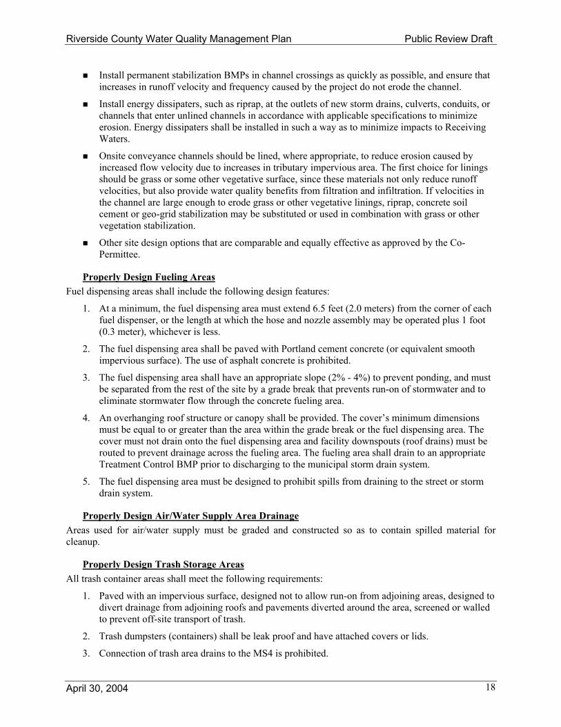
Install permanent stabilization BMPs in channel crossings as quickly as possible, and ensure that increases in runoff velocity and frequency caused by the project do not erode the channel.
Install energy dissipaters, such as riprap, at the outlets of new storm drains, culverts, conduits, or channels that enter unlined channels in accordance with applicable specifications to minimize erosion. Energy dissipaters shall be installed in such a way as to minimize impacts to Receiving Waters.
Onsite conveyance channels should be lined, where appropriate, to reduce erosion caused by increased flow velocity due to increases in tributary impervious area. The first choice for linings should be grass or some other vegetative surface, since these materials not only reduce runoff velocities, but also provide water quality benefits from filtration and infiltration. If velocities in the channel are large enough to erode grass or other vegetative linings, riprap, concrete soil cement or geo-grid stabilization may be substituted or used in combination with grass or other vegetation stabilization.
Other site design options that are comparable and equally effective as approved by the Co-Permittee.
Properly Design Fueling Areas Fuel dispensing areas shall include the following design features:
1. At a minimum, the fuel dispensing area must extend 6.5 feet (2.0 meters) from the corner of each fuel dispenser, or the length at which the hose and nozzle assembly may be operated plus 1 foot (0.3 meter), whichever is less.
2. The fuel dispensing area shall be paved with Portland cement concrete (or equivalent smooth impervious surface). The use of asphalt concrete is prohibited.
3. The fuel dispensing area shall have an appropriate slope (2% - 4%) to prevent ponding, and must be separated from the rest of the site by a grade break that prevents run-on of stormwater and to eliminate stormwater flow through the concrete fueling area.
4. An overhanging roof structure or canopy shall be provided. The cover’s minimum dimensions must be equal to or greater than the area within the grade break or the fuel dispensing area. The cover must not drain onto the fuel dispensing area and facility downspouts (roof drains) must be routed to prevent drainage across the fueling area. The fueling area shall drain to an appropriate Treatment Control BMP prior to discharging to the municipal storm drain system.
5. The fuel dispensing area must be designed to prohibit spills from draining to the street or storm drain system.
Properly Design Air/Water Supply Area Drainage Areas used for air/water supply must be graded and constructed so as to contain spilled material for cleanup.
Properly Design Trash Storage Areas All trash container areas shall meet the following requirements:
1. Paved with an impervious surface, designed not to allow run-on from adjoining areas, designed to divert drainage from adjoining roofs and pavements diverted around the area, screened or walled to prevent off-site transport of trash.
2. Trash dumpsters (containers) shall be leak proof and have attached covers or lids.
3. Connection of trash area drains to the MS4 is prohibited.

Riverside County Water Quality Management Plan Public Review Draft
April 30, 2004 19
4. Trash compactors shall be roofed and set on a concrete pad. The pad shall be a minimum of one foot larger all around than the trash compactor and sloped to drain to a sanitary sewer line.
Properly Design and Maintain Loading Docks The design of loading/unloading dock areas shall include the following:
Cover loading dock areas, or design drainage to preclude run-on and runoff.
Direct connections to the municipal storm drain system from below-grade loading docks (truck wells) or similar structures are prohibited. Stormwater runoff from a below-grade loading dock may only be discharged to the MS4 when designed to use a Treatment Control BMP applicable to the use.
Loading docks shall be kept in a clean and orderly condition through a regular program of sweeping and litter control and immediate cleanup of spills and broken containers. Cleanup procedures should minimize or eliminate the use of water. If washdown water is used, it must be properly disposed (containment, collection, and disposal to sanitary sewer) and not discharged to the MS4. The project-specific WQMP shall describe the frequency for implementing loading dock housekeeping measures and the party responsible.
Properly Design Maintenance Bays Maintenance bays shall include the following:
Repair/maintenance bays shall be indoors; or, designed to preclude run-on and runoff.
Design a repair/maintenance bay drainage system to capture all wash water, leaks and spills. Provide impermeable berms, drop inlets, trench catch basins, or overflow containment structures around repair bays to prevent spilled materials and washdown waters from entering the storm drain system. Connect drains to a sump for collection and disposal. Discharge from the repair/maintenance bays to the municipal storm drain system is prohibited.
Properly Design Vehicle and Equipment Wash Areas The discharge of wash waters to the MS4 is prohibited. Therefore, Projects that include areas for washing/steam cleaning of vehicles or equipment shall include the following design features:
Wash areas shall be contained and covered with a roof or overhang or adequate surplus storage to contain and utilize all precipitation.
Provide a wash rack or wash racks connected to the sanitary sewer in accordance with sewering agency guidelines and prior approval. The sewering agency may require discharge monitoring. If the facility recycles wash water and is not connected to the sanitary sewer, wastes must be properly contained and disposed.
Design an equipment wash area drainage system to capture all wash water. Provide impermeable berms, drop inlets, trench catch basins, or overflow containment structures around equipment wash areas to prevent wash waters from entering the MS4. Connect drains to a sump for collection and disposal.
Surface runoff and roof drains shall be directed away from wash racks unless approved by the sanitary sewering agency.
Properly Design Outdoor Material Storage Areas Where plans propose outdoor storage containers for oils, fuels, solvents, coolants, wastes, and other chemicals, the areas where these materials are to be used or stored must be protected by secondary containment structures such as a low containment berm, dike, or curb, designed to the satisfaction of the

Riverside County Water Quality Management Plan Public Review Draft
April 30, 2004 20
Co-Permittee. Materials or products that are stored outside and that have the potential to cause pollutant discharges shall be protected from rainfall, runoff, run-on, and wind erosion by design and use of:
A cabinet, shed, or similar structure that prevents contact with runoff or spillage to the MS4.
A paved storage area and sufficiently impervious to contain leaks and spills.
A roof or awning to minimize direct precipitation and collection of stormwater within the secondary containment area. Stormwater that collects within a secondary containment structure must not be discharged to the street or the MS4.
Properly Design Outdoor Work Areas or Processing Areas Where vehicle or equipment repair/maintenance occurs, impermeable berms, trench drains, or containment structures shall be provided around the areas to eliminate or reduce spilled materials and wash-down waters from entering the street or the MS4. Surface runoff or roof drains shall be directed away from these contained work areas. Sidewalls and canopies may be used to meet this requirement.
Outdoor process equipment operations, such as rock grinding or crushing, painting or coating, grinding or sanding, degreasing or parts cleaning, landfills, waste piles, and wastewater and solid waste handling, treatment, and disposal, and other operations shall adhere to the following requirements.
Cover or enclose areas that would be the sources of pollutants or slope the area toward a sump.
Grade or berm area to prevent run-on from surrounding areas.
Storm drain inlets connected to the MS4 are prohibited within these outdoor work or process areas.
Where wet material processing occurs (e.g. electroplating), secondary containment structures (not double wall containers) shall be provided to hold spills resulting from accidents or leaking tanks or equipment.
Provide Wash Water Controls for Food Preparation Areas Food establishments (per State Health & Safety Code 27520) shall have either contained areas or sinks, each with sanitary sewer connections for disposal of wash waters containing kitchen and food wastes. If located outside, the contained areas or sinks shall also be structurally covered to prevent entry of stormwater. Adequate signs shall be provided and appropriately placed stating the prohibition of discharging washwater to the MS4.
Provide Community Car Wash Racks In multi-family Projects where car washing or rinsing is not specifically prohibited via CC&Rs or other acceptable means, and in Projects having a common parking area where car washing or rinsing is not specifically prohibited via CC&Rs or other acceptable means, a designated car washing and rinsing area that does not drain directly to a storm drain shall be provided for common usage. Wash and rinse waters from this area must either be directed to the sanitary sewer (with prior approval of the sewering agency), to an engineered filtration system, or an equally effective alternative prior to discharging to the MS4.
4.5.3 Treatment Control BMPs Treatment Control BMPs must be selected with respect to identified pollutants of concern. Treatment Control BMPs must be designed to treat the stormwater quality flow or the stormwater quality volume from a Project. Treatment Control BMPs may also be provided offsite or through a regionally-based Treatment Control BMP (see section 5.0).
Exhibit C to this WQMP summarizes expected performance of Treatment Control BMPs in removing various pollutants of concern. For more specific information on the pollutant removal capabilities of

Riverside County Water Quality Management Plan Public Review Draft
April 30, 2004 21
various BMPs, refer to the California Stormwater Quality Association’s, “Stormwater Best Management Practices Handbook for New Development and Redevelopment” (CASQA, 2003). Subsequent sections of this WQMP provide guidance for determining the flow (Section 4.5.3.4) or volume (Section 4.5.3.5) of runoff from a Project to be treated via Treatment Control BMPs. The Riverside County Stormwater Quality Best Management Practice Design Handbook, which is included as Exhibit D, provides more detailed guidance.
The obligation to install Treatment Control BMPs at Project site is met if, for a common scheme of development, BMPs are constructed with the requisite capacity to serve the entire common scheme, even if certain phases of the common scheme may not have BMP capacity located on that phase. BMP capacity must be functional before any phased work begins, thus may not be added on at the end of phased development.
If the Treatment Control BMP selected for the project functions by infiltration, the BMP shall not violate the requirements set forth in 40 CFR 144 for Class V Injection Wells [will provide web address] or any potential local infiltration requirements. For purposes of identifying local infiltration requirements, the Co-Permittee will assist Project applicants in identifying groundwater management agencies that may have established such requirements. In addition, Treatment Control BMPs that allow infiltration shall not cause or contribute to an exceedance of groundwater quality objectives, shall not be used in industrial or high vehicular traffic areas (25,000 or greater average daily traffic), must be located at least 100 feet horizontally from any water supply well, must be at least 10 feet vertically above the historic high groundwater mark, and shall not cause a nuisance or pollution as defined in Water Code Section 13050 [will provide web address]. Additional resources for the appropriate siting of infiltration BMPs is Caltrans Report No. CTSW-RT-03-025, Infiltration Basin Site Selection Study (June 2003)13 or USEPA Report No. EPA/600/R-94-051, Potential Groundwater Contamination from Intentional and Non-Intentional Stormwater Infiltration (1994).
4.5.3.1 Flow Based Treatment Control BMPs
Vegetated Filter Strips Vegetated filter strips are uniformly graded areas of dense vegetation designed to treat sheet flow stormwater runoff. Pollutants are removed by filtering and through settling of sediment and other solid particles as the design flow passes through (not over) the vegetation. Filter strips are usually as wide as the drainage area and must be long enough in the flow direction to adequately treat the runoff. Concentrated flows are redistributed uniformly across the top of the strip with a level spreader. A grass swale, sand filter, or infiltration BMP is recommended in conjunction with a filter strip.
Vegetated filter strips require frequent landscape maintenance. Maintenance requirements typically include grass or shrub-growing activities such as irrigation, mowing, trimming, removal of invasive species, and replanting when necessary. Consider use of duplicate facilities such that one one-half of the facility can be taken out of service to allow for maintenance without reducing the required level of treatment performance. This is especially helpful for vegetated filter strips that need to be dry before they can be mowed.
Vegetated Swales A vegetated swale is a wide, shallow densely vegetated channel that treats stormwater runoff as it is slowly conveyed into a downstream system. These swales have very shallow slopes in order to allow maximum contact time with the vegetation. The depth of water of the design flow should be less than the height of the vegetation. Contact with vegetation improves water quality by plant uptake of pollutants, removal of sediment, and an increase in infiltration. Overall the effectiveness of grass swales is limited and they are recommended in combination with other BMPs.
13 Web address to be provided.

Riverside County Water Quality Management Plan Public Review Draft
April 30, 2004 22
Vegetated swales require a thick vegetative cover to function properly. They usually require normal landscape maintenance activities such as irrigation and mowing to maintain pollutant removal efficiency. The application of fertilizers and pesticides should be minimized. Consider use of duplicate facilities such that one one-half of the facility can be taken out of service to allow for maintenance without reducing the required level of treatment performance. This is especially helpful for vegetated swales that need to be dry before they can be mowed.
Water Quality Inlet A water quality inlet is a device that removes oil and grit from stormwater runoff before the water enters the storm drain system. It consists of one or more chambers that promote sedimentation of coarse materials and separation of free oil from stormwater. Manufacturers have created a variety of configurations to accomplish this. A specific model can be selected from the manufacturer based on the design flow rate. A water quality inlet is generally used for pretreatment before discharging into another type of BMP.
Water quality inlet (WQI) maintenance is site-specific due to variations in sediment and hydrocarbon by-products, which may require disposal as hazardous waste. Establishment of a maintenance schedule is helpful for ensuring proper maintenance, because the WQIs are underground and can easily be neglected. High sediment loads can interfere with the ability of the WQI to effectively separate oil and grease from the runoff.
Other BMPs In some cases, other flow-based BMPs, proprietary BMPs or combinations of BMPs may be appropriate for a development. Such BMPs or combinations of BMPs may be employed on a site-specific basis as approved by the Co-Permittee. The appropriate BMP(s) for a Project should be determined based on the size of the project area and the types of pollutants that will be found in the development runoff.
4.5.3.2 Volume Based Treatment Control BMPs
Extended Detention Basin An extended detention Basin is a permanent basin sized to detain and slowly release the design volume of stormwater, allowing particles and associated pollutants to settle out. The basin outlet is designed to slowly release this runoff over a set drawdown period. An inlet forebay section and an inlet energy dissipater minimize erosion from entering flows, while erosion protection at the outlet prevents damage from exiting flows. The bottom of the basin slopes towards the outlet at an approximate grade of two percent, and a low flow channel conveys incidental flows directly to the outlet end of the basin. The basin should be vegetated earth in order to allow some infiltration to occur, although highly pervious soils may require an impermeable liner to prevent groundwater contamination. Proper turf management is also required to ensure that the vegetation does not contribute to water pollution through pesticides, herbicides, or fertilizers. A permanent micro-pool should not be included due to vector concerns. Extended detention basins can also be used to reduce the peaks of small run-off events for flood control purposes.
Extended detention basins require inspection semi-annually and after significant storm events to identify potential problems early. Most maintenance efforts will need to be directed toward vegetation management and vector control, which may focus on basic housekeeping practices such as removal of debris accumulations and vegetation management to ensure that the basin dewaters completely, within the set drawdown time, to prevent creating vector habitats.
Infiltration Basin Infiltration basins perform better in well-drained permeable soils. Infiltration basins in areas of low permeability can clog within a couple of years, and require more frequent inspection and maintenance. The use and regular maintenance of pretreatment BMPs will significantly minimize maintenance

Riverside County Water Quality Management Plan Public Review Draft
April 30, 2004 23
requirements for the basin. Spill response procedures and controls should be implemented to prevent spills from reaching the infiltration basin. Particular care is required where the area upstream of the infiltration BMP may not be fully stabilized, or in existing developments where upstream areas may become destabilized due to construction work, lack of maintenance, fire, or other actions. In these cases, measures to prevent sediment from entering and clogging the BMP are necessary until the drainage area is stabilized. This BMP may require groundwater monitoring. Basins should not be put into operation until the upstream tributary area is stabilized.
Infiltration Trench An infiltration trench is an excavated trench that has been refilled with a gravel and sand bed capable of holding the design volume of stormwater runoff. The runoff is stored in the trench over a period of time during which it slowly infiltrates back into the naturally pervious surrounding soil. This infiltration process effectively removes soluble and particulate pollutants, however it is not intended to trap coarse sediments. These trenches also include a bypass system for volumes greater than the design capture volume, and a perforated pipe observation well to monitor water depth.
Infiltration trenches require an effective pretreatment, such as vegetated buffer strips, to remove sediment and minimize clogging. If the trench clogs, it may be necessary to remove and replace all or part of the filter fabric and possibly the coarse aggregate. Maintenance should be concentrated on the pretreatment practices, such as buffer strips and swales upstream of the trench to ensure that sediment does not reach the infiltration trench. Particular care is required where the area upstream of the infiltration BMP may not be fully stabilized, or in existing developments where upstream areas may become destabilized due to construction work, lack of maintenance, fire, or other actions. In these cases, measures to prevent sediment from entering and clogging the BMP are necessary until the drainage area is stabilized. Regular inspection should determine if the sediment removal structures require routine maintenance. Infiltration basins should not be put into operation until the upstream tributary area is stabilized.
Sand Filter Sand filters clog easily when subjected to heavy sediment loads. Sediment reducing pretreatment practices, such as vegetated buffer strips or vegetated swales, placed upstream of the filter should be maintained properly to reduce sediment loads into the filter. Media filters should drain within the set drawdown time to minimize vector habitat. Maintenance will need to focus on basic housekeeping practices such as removal of debris accumulations and vegetation management (within media filter) to prevent clogs and/ or standing water. Materials such as sand, gravel, filter cloth, or filter media must be disposed of properly and in accordance with all applicable laws.
Porous Pavement Porous Pavement is an infiltration BMP that consists of porous pavement blocks placed over a shallow recharge bed of sand and gravel. It is typically restricted to low volume parking areas that do not receive significant offsite runoff. The modular pavement blocks allow water to seep into the recharge bed, where the sand and gravel layers percolate the design volume into the natural surrounding soils. Porous Pavement can be used for areas of up to 10 acres.
Other BMPs In some cases, other volume-based BMPs, proprietary BMPs or combinations of BMPs may be appropriate for a development. Such BMPs or combinations of BMPs may be employed on a site-specific basis as approved by the Co-Permittee. The appropriate BMP(s) for a Project should be determined based on the size of the project area and the types of pollutants that will be found in the development runoff.

Riverside County Water Quality Management Plan Public Review Draft
April 30, 2004 24
4.5.3.3 Design Basis for Treatment Control BMPs The primary parameter for designing Treatment Control BMPs is to treat the stormwater quality design flow (QBMP) or the stormwater quality design volume (VBMP) of the stormwater runoff. Table 3 lists Treatment Control BMPs and the primary design basis (flow-based or volume-based) to be used for designing BMPs.

Riverside County Water Quality Management Plan Public Review Draft
April 30, 2004 25
Table 3. Design Basis for Treatment Control BMPs
Treatment Control BMP Design Basis Vegetated Filter Strips Vegetated Swales Water Quality Inlets
QBMP
Extended Detention Basin Sand Filter Porous Pavement Detention Infiltration Basin Infiltration Trench
VBMP
Other BMPs QBMP or VBMP on Case-Specific Basis
4.5.3.4 Flow-Based Design Flow-based BMP design standards apply to BMPs whose primary mode of pollutant removal depends on the rate of flow of runoff through the BMP. The following steps describe the approach for application of the flow-based BMP design criteria. A detailed design procedure and worksheet are provided in the Riverside County Stormwater Quality Best Management Practice Design Handbook (see Exhibit Z).
Identify the drainage area that drains to the proposed BMP. This includes all areas that will contribute runoff to the proposed BMP, including pervious areas, impervious areas, and runoff from off-site areas that commingle with site runoff, whether or not they are directly or indirectly connected to the BMP. Calculate this area in units of acres. Determine the impervious percentage of area in the tributary area.
Determine the Runoff Coefficient for each soil type using Table D-1 from Exhibit D for each type of soil with the site’s impervious area percentage. This is based on a uniform rainfall intensity of 0.2 inch/hour.
Determine the percentages of each soil type within the drainage area.
Determine the Site’s Aggregate Runoff Coefficient by multiplying the fraction of drainage area for each soil type by its associated Runoff Coefficient.
Determine the BMP Design Flow Rate using the equation QBMP = C x I x A
Where A = Tributary Area to the BMP I = Design Rainfall intensity, 0.2 inch/hour
C = Runoff Coefficient, based upon a Rainfall Intensity = 0.2 inch/hour 4.5.3.5 Volume-Based Design Volume-based BMP design standards apply to BMPs whose primary mode of pollutant removal depends on the volumetric capacity of the BMP. Volume-based Treatment Control BMPs shall be designed to infiltrate or treat the design volume of runoff. Use the following steps to determine the design volume. A detailed design procedure and worksheet are provided in the Riverside County Stormwater Quality Best Management Practice Design Handbook (see Exhibit Z). This method for determining the design volume is based on capturing a 24-hour 85th percentile storm event as determined using rain gages throughout Riverside County with the greatest periods of record
Determine the BMP Drainage Area that drains to the proposed BMP. This includes all areas that will contribute runoff to the proposed BMP, including pervious areas, and runoff from off-site areas that commingle with site runoff, whether or not they are directly or indirectly connected

Riverside County Water Quality Management Plan Public Review Draft
April 30, 2004 26
to the BMP. Calculate this area in acres. Determine the impervious percentage of area in the tributary area.
Calculate the composite Runoff Coefficient “C-Factor” for the BMP Drainage Area. Use the following equation based on the WEF/ASCE Method: C = 0.858i3 – 0.78i2 + 0.774i + 0.04, where i = drainage area imperviousness ratio, which is equal to the total impervious area divided by the total tributary area.
Determine the Unit Storage Volume for the 85% annual runoff event by following methodology specified in the Riverside County Stormwater Quality BMP Design Handbook (see Exhibit Z).
Calculate the required capture volume of the BMP by multiplying the BMP Drainage Area by the Unit Storage Volume to give the BMP Design Storage Volume. Due to the mixed units that result (e.g., acre-inches, acre-feet) it is recommended that the resulting volume be converted to cubic feet for use during design.
4.5.4 Equivalent Treatment Control Alternatives Where on-site Treatment Control BMPs are determined to be infeasible or impracticable, equivalent treatment may be provided off site when approved by the Co-Permittee. Off-site Treatment Control BMPs must:
Be located in the same watershed as the project site.
Treat a volume and/or flow equal to or greater than the treatment volume and/or flow calculated for the project site using the guidance in this WQMP.
Treat a pollutant loading equal to or greater than the pollutant loading from the project site.
Address the pollutants of concern and hydrologic conditions of concern for the project site.
Be operational prior to the construction phase of the Project.
Off-site BMPs must be implemented prior to Receiving Waters.
In addition, Site Design and Source Control BMPs must continue to be implemented at the project site in accordance with this WQMP.
Subject to approval by the Co-Permittee, off-site Treatment Control BMPs with excess capacity may be used to meet the treatment needs of additional Projects as long as each Project meets the requirements of this section and such that the requirements are met when the Projects are combined. For example, if the treatment volume for Project 1 is “A” and the treatment volume for Project 2 is “B”, then an off-site Treatment Control BMP would need to have a treatment volume capacity of at least “A+B” in order to treat the runoff from both Project 1 and Project 2. Similar provisions apply for flows and pollutants.
These provisions are supplemental to the provisions in Section 4 for regionally-based water quality control programs. While similar in nature, these provisions are intended to be implemented primarily on a smaller, more local basis. For example, a single developer of separate but adjacent Projects might utilize the provisions of this section to propose that controls for both Projects be located on one of the two separate sites, or possibly even propose that the controls for both sites be located on a third site.
4.6 Operation and Maintenance Operation and maintenance (O&M) requirements for all structural Source Control and Treatment Control BMPs shall be identified in the project-specific WQMP. The project-specific WQMP shall address the following:
Identification of each BMP that requires O&M.

Riverside County Water Quality Management Plan Public Review Draft
April 30, 2004 27
Thorough description of O&M activities, the O&M process, and the handling and placement of any wastes.
BMP start-up dates.
Schedule of the frequency of O&M for each BMP.
Identification of the parties (name, address, and telephone number) responsible for O&M, including a written agreement with the entities responsible for O&M.
Self-inspections and record-keeping requirements for BMPs (review local specific requirements regarding self-inspections and/or annual reporting), including identification of responsible parties for inspection and record- keeping.
Thorough descriptions of water quality monitoring, if required by the Co-Permittee.
Co-Permittees should have authority to maintain the BMP, if necessary, and invoice the owner for costs.
4.7 Funding A funding source or sources for the O&M of each Treatment Control BMP identified in the project-specific WQMP must be identified. By certifying the project-specific WQMP (see Section 4.8), the Project applicant is certifying that the funding responsibilities have been addressed and will be transferred to future owners. One example of how to adhere to the requirement to transfer O&M responsibilities is to record the project-specific WQMP against the title to the property.

Riverside County Water Quality Management Plan Public Review Draft
April 30, 2004 28
4.8 WQMP Certification A project-specific WQMP shall include a certification by the project owner/developer accepting responsibility for implementation, operation, maintenance, repair, replacement, and inspection of all BMPs described in the approved project-specific WQMP. The following certification, or a substantially similar version, shall be included in each project-specific WQMP prior to approval by the Co-Permittee. This certification statement is included in the WQMP Template provided in Exhibit A.
WQMP Certification
This Water Quality Management Plan has been prepared for [insert owner of project] by [insert name of firm preparing WQMP] for the project known as ___________________ at [insert street address] . The undersigned is authorized to approve implementation of the provisions of this Water Quality Management Plan. A copy of this Water Quality Management Plan will be maintained at the project site or project office. This Water Quality Management Plan will be reviewed with the facility operator, facility supervisors, employees, tenants, maintenance and service contractors, or any other party (or parties) having responsibility for implementing portions of this Water Quality Management Plan. The undersigned will strive to have this Water Quality Management Plan carried out by successors consistent with the [Insert Region Name] Drainage Area Management Plan and the intent of other applicable water quality permits or programs. Owner’s Signature Date Owner’s Printed Name Owner’s Title/Position

Riverside County Water Quality Management Plan Public Review Draft
April 30, 2004 29
5.0 Regionally-Based Treatment Control For watersheds, sub-watershed, drainage areas, and other areas covered by a comprehensive Master Plan of Drainage approved by the Co-Permittee(s) (or developed as part of a Master Plan of Drainage for a Specific Plan or a cooperative group of developments), regionally-based Treatment Control BMPs are an alternative approach to project-specific (onsite) Treatment Control BMP implementation. Regionally-based BMPs may provide a more effective and cost efficient runoff Treatment Control mechanism for multiple Projects within the area covered by the comprehensive master plan of drainage and water quality.
When regionally-based Treatment Control BMPs are utilized, the Project must continue to implement Site Design and Source Control BMPs. Regionally-based Treatment Control BMPs can treat stormwater from several source areas at a single or multiple downstream location(s). This approach can be effective when limited space is available for structural BMPs in Project areas. Regionally-based Treatment Control BMPs will be considered for acceptance by the Co-Permittee as an alternative to on-site measures if the Project applicant demonstrates the following:
There is adequate capacity in the regionally-based Treatment Control BMP to address the volume-based and flow-based treatment needs of the project.
The regionally-based Treatment Control BMP addresses the project’s pollutants of concern (after considering Site Design and Source Control BMPs that must still be implemented at the project site).
Projects intending to rely on the regionally-based Treatment Control BMP must incorporate Project-specific BMPs to address any pollutant of concern from the project not addressed by the regionally-based Treatment Control BMP.
The Project applicant identifies the party responsible for the funding, operation, maintenance, and administration of the regionally-based Treatment Control BMP.
The Project applicant has secured rights from the owner/operator to participate in the regionally-based BMP solution.
The Project applicant has met all of the requirements imposed for participation in the regionally-based BMP, including funding and operation and maintenance requirements, and contingency planning.
The regionally-based BMP will be-on line, operable, and ready to receive flows from the project site prior to issuance of the first discretionary permit sought. Site Design BMPs and Source Control BMPs are implemented at the Project site.
Waters of the United States will not be utilized to transport untreated runoff to the regional facility.
Projects participating in regional Treatment Control BMPs may rely upon the regional program during the discretionary review process subject to a discussion of how the Project will participate in the program. At the discretion of the Co-Permittee(s) with jurisdiction, the Project-specific WQMP may be required to identify its stormwater contribution to the regional program and how it will affect cumulative water quality impacts in the regional watershed. Removal effectiveness, cost, maintenance, and construction timing affect whether a regional-based approach is more appropriate than site-specific approaches.
Regional facilities proposed as part of the Lake Mathews Master Drainage Plan and the Retrofit Siting Study conducted by the Permittees could provide Regional Treatment for Projects. The Permittee(s) with jurisdiction over the Project should be contacted to determine if other applicable regional BMPs exist or are proposed. A Project that proposes to utilize a regional BMP must verify that the regional BMP addresses all pollutants of concern from the Project. A Project’s pollutants of concern that are not addressed by the regional BMP will require a separate Treatment Control BMP (or BMPs).

Riverside County Water Quality Management Plan Public Review Draft
April 30, 2004 30
6.0 Changes in Site Development or Ownership
6.1 Changes in Site Development The WQMP must be updated to reflect significant proposed changes in the site’s runoff characteristics. Significant changes in the site’s runoff characteristics are deemed to potentially occur whenever site work requiring a grading permit is proposed or where exterior work requiring a building permit is proposed. Under these circumstances, the owner/developer shall contact the Co-Permittee and provide sufficient information for the Co-Permittee to determine whether the existing project-specific WQMP is still appropriate. If deemed inappropriate by the Co-Permittee for proposed conditions, the owner/developer shall revise the WQMP to address the cumulative changes to the site and submit the revised project-specific WQMP to the Co-Permittee for review and approval prior to issuance of the first discretionary permit.
Significant changes in the site’s runoff characteristics shall be deemed to occur whenever there is a change in use necessitating a conditional use permit (for example, changing from retail to restaurant), or when proposed changes to the site fall into one or more of the Project categories that require a project-specific WQMP. Under these conditions, a revised or completely new project-specific WQMP shall be developed and submitted for review and approval by the Co-Permittee.
6.2 Changes in Site Ownership For sites with a fully implemented WQMP, the WQMP requirements shall transfer to all future owners of the project site. Recording the WQMP requirements against the title to the property is one way to effectively notify potential buyers and future owners of properties of their responsibilities for the WQMP. New owners have the option to adopt the existing WQMP, to amend the WQMP, or to develop a new WQMP. If the WQMP is amended or if a new WQMP is developed, the amended or new WQMP must be in accordance with this WQMP, must address cumulative changes to the project site, and must be submitted to the Co-Permittee for review and approval.
7.0 Waiver of Treatment Control BMP Requirements Treatment Control BMPs may be eliminated, in some cases, if Site Design BMPs and Source Control BMPs are demonstrated to effectively eliminate pollutant discharges. Upon presentation of a project-specific WQMP with sufficient Site Design and Source Control BMPs to meet the WQMP objectives, and upon specific written request by the Project applicant, the Co-Permittee may approve a project-specific WQMP that does not include Treatment Control BMPs. The Project applicant is responsible for the presentation of evidence, including but not limited to monitoring data and special studies, to support the attainment of the WQMP objectives through Site Design and Source Control BMPs only.
The Co-Permittee may waive the requirement of incorporating Treatment Control BMPs into a project-specific WQMP on a case-by-case basis if infeasibility can be established. In considering a waiver the Co-Permittees should review the CEQA documentation for the Project to determine whether a significant unmitigated impact or cumulative impact was identified that was the subject of a statement of overriding considerations. A Co-Permittee shall only grant a waiver of infeasibility when all available Treatment Control BMPs have been considered and rejected as infeasible and/or the cost of implementing Treatment Control BMPs greatly outweighs the pollution control benefit. The burden of proof is on the Project applicant to demonstrate that all available Treatment Control BMPs are infeasible. Co-Permittees shall notify the Executive Officer of the Regional Water Quality Control Board by Certified Mail (with Return Receipt) within thirty (30) calendar days after issuing a waiver. The notification shall include a copy of the waiver documentation and a copy of the Project’s WQMP.

Riverside County Water Quality Management Plan Public Review Draft
April 30, 2004 31
A Co-Permittee may waive the requirement of incorporating Treatment Control BMPs into a project-specific WQMP for Projects within those portions of the Permit Area that will not result in a discharge to Receiving Waters under the design sizing criteria described in Sections 4.5.3.4 and 4.5.3.5.

Riverside County Water Quality Management Plan Exhibit A Public Review Draft
April 30, 2004 A-1
Project-Specific WQMP Template

Project Specific Water Quality Management Plan
For:
Start Here…Triple Click here to insert Project Name-then TAB to next field
TRACT NO. INSERT TRACT NUMBER DESIGN REVIEW NO. INSERT DESIGN REVIEW NUMBER
Prepared for: Insert Name of Owner/Developer-then TAB.
Insert Address 1 and press ENTER to insert Address 2 or TAB to next field. Insert City, State, ZIP-then TAB.
Insert Owner's/Developer's Telephone Number-then TAB.
Prepared by: Insert Company Name-then TAB.
Insert Address-then TAB. Insert City, State, ZIP-then TAB.
Insert Telephone-then TAB Insert Name and Title of Preparer-then TAB.
WQMP Preparation/Revision Date: Insert Date

Water Quality Management Plan (WQMP) Start Here…Triple Click here to insert Project Name-then TAB to next field
Insert Date
i
OWNER’S CERTIFICATION This project-specific Water Quality Management Plan (WQMP) for:
Start Here…Triple Click here to insert Project Name-then TAB to next field has been prepared for Insert Name of Owner/Developer-then TAB. by Insert Company Name-then TAB..
This WQMP is intended to comply with the requirements of the City/County of Insert City or County Name INSERT TRACT NUMBER, also under the following Parcel Map, Condition, and/or Site Development Permit/Application Numbers:
Insert applicable numbers associated with Project
The undersigned, while owners of the property described above, shall be responsible for the implementation of the provisions of this WQMP and will ensure that this WQMP is amended as appropriate to reflect up-to-date conditions of the project.
This WQMP shall be reviewed with the facility operator, facility supervisors, employees, tenants, maintenance and service contractors, and/or any other party having responsibility for implementing this Water Quality Management Plan. Once the undersigned transfers interest(s) in the property described above, the successors-in-interest shall bear the aforementioned responsibility to implement and amend this WQMP. An appropriate number of approved and signed copies of this document shall be available on the project site in perpetuity.
Owner’s Signature Date Owner’s Printed Name Owner’s Title/Position Insert Address 1 and press ENTER to insert Address 2 or TAB to next field. Insert City, State, ZIP-then TAB. Insert Owner's/Developer's Telephone Number-then TAB.
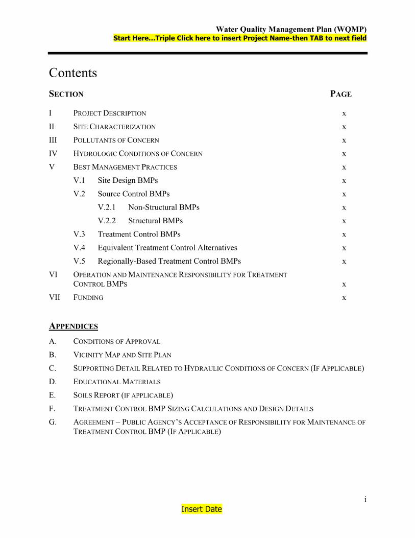
Water Quality Management Plan (WQMP) Start Here…Triple Click here to insert Project Name-then TAB to next field
Insert Date
i
Contents SECTION PAGE I PROJECT DESCRIPTION x
II SITE CHARACTERIZATION x
III POLLUTANTS OF CONCERN x
IV HYDROLOGIC CONDITIONS OF CONCERN x
V BEST MANAGEMENT PRACTICES x
V.1 Site Design BMPs x
V.2 Source Control BMPs x
V.2.1 Non-Structural BMPs x
V.2.2 Structural BMPs x
V.3 Treatment Control BMPs x
V.4 Equivalent Treatment Control Alternatives x
V.5 Regionally-Based Treatment Control BMPs x
VI OPERATION AND MAINTENANCE RESPONSIBILITY FOR TREATMENT CONTROL BMPS x
VII FUNDING x
APPENDICES A. CONDITIONS OF APPROVAL
B. VICINITY MAP AND SITE PLAN
C. SUPPORTING DETAIL RELATED TO HYDRAULIC CONDITIONS OF CONCERN (IF APPLICABLE)
D. EDUCATIONAL MATERIALS
E. SOILS REPORT (IF APPLICABLE)
F. TREATMENT CONTROL BMP SIZING CALCULATIONS AND DESIGN DETAILS
G. AGREEMENT – PUBLIC AGENCY’S ACCEPTANCE OF RESPONSIBILITY FOR MAINTENANCE OF TREATMENT CONTROL BMP (IF APPLICABLE)

Water Quality Management Plan (WQMP) Start Here…Triple Click here to insert Project Name-then TAB to next field
Insert Date
1
I. Project Description The project description accurately describes the following characteristics of the project:
Project owner and WQMP preparer;
Project location;
Project size;
Standard Industrial Classification (SIC), if applicable;
Location of facilities;
Activities and location of activities;
Materials Storage and Delivery Areas;
Wastes generated by project activities.
Project Owner: Insert Name of Owner/Developer-then TAB.
Insert Address 1 and press ENTER to insert Address 2 or TAB to
next field.
Insert City, State, ZIP-then TAB.
Telephone: Insert Owner's/Developer's Telephone Number-then
TAB.
WQMP Preparer: Insert Company Name-then TAB.
Insert Address-then TAB.
Insert City, State, ZIP-then TAB.
Insert Telephone-then TAB

Water Quality Management Plan (WQMP) Start Here…Triple Click here to insert Project Name-then TAB to next field
Insert Date
2
Project Site Address: Insert Project Street Address
Insert Project City, State, ZIP
APN Number(s): Insert APN Number(s) - ENTER for new line
Thomas Bros. Map: Insert Thomas Bros. Map page(s) and corresponding grid(s)
Project Watershed: Enter appropriate watershed: Santa Ana, Santa Margarita or
Whitewater
Sub-watershed: Enter sub-watershed, if known (i.e., salt creek, san jacinto,
warm springs, etc.)
Project Site Size: Insert site size (indicate acres or square feet)
Standard Industrial Classification (SIC) Code: Insert SIC, code, if applicable
Formation of Home Owners’ Association (HOA)/Property Owners Association (POA): Y/N
Appendix A of this project-specific WQMP includes a complete copy of the final Conditions of Approval. Appendix B of this project-specific WQMP includes a Vicinity Map and a Site Plan for the project. The Site Plan included as part of Appendix B depicts the following project features:
Location of all structural BMPs, including Treatment Control BMPs;
Landscaped areas;
Paved areas and intended uses (i.e., parking, outdoor work area, outdoor material storage area, sidewalks, patios, tennis courts, etc.);
Number and type of structures and intended uses (i.e., buildings, tenant spaces, dwelling units, community facilities such as pools, recreation facilities, tot lots, etc.);
Infrastructure (i.e., streets, storm drains, etc.) that will revert to public agency ownership and operation;
Location of existing and proposed public and private storm drain facilities (i.e., storm drains, channels, basins, etc.), including catch basins, and other inlets/outlet structures;
Location(s) of Receiving Waters and points where onsite flows exit the property/project site;
Proposed drainage areas boundaries, including tributary offsite areas, for each location where flows exits the property/project site;
Pre- and post-project topography.

Water Quality Management Plan (WQMP) Start Here…Triple Click here to insert Project Name-then TAB to next field
Insert Date
3
II. Site Characterization Land Use Designation or Zoning: Insert current/proposed zoning or land use
designation
Current Property Use: Insert actual use of property (i.e., undeveloped,
previously developed but vacant, etc.)
Proposed Property Use: Insert proposed use of property
Availability of Soils Report: Y/N (Note: a soils report is required if infiltration
BMPs are utilized)
Receiving Waters for Urban Runoff from Site
Receiving Waters 303(d) List Impairments
Designated Beneficial Uses
Proximity to RARE Beneficial Use
Insert name of 1st receiving
water
List any 303(d) impairments of 1st receiving water, including TMDL pollutant limitations
Insert designated beneficial use of 1st receiving water
Insert distance of project to RARE-designated waters (indicate whether feet, yards, or miles)
insert name of 2nd receiving
water
List any 303(d) impairments of 2nd receiving water, including TMDL pollutant limitations
Insert designated beneficial use of 2nd receiving water
Insert distance of project to RARE-designated waters (indicate whether feet, yards, or miles)
Insert name of 3rd receiving
water
List any 303(d) impairments of 3rd receiving water, including TMDL pollutant limitations
Insert designated beneficial use of 3rd receiving water
Insert distance of project to RARE-designated waters (indicate whether feet, yards, or miles)
Insert Name Of 4th Receiving
Water
List any 303(d) impairments of 4th receiving water, including TMDL pollutant limitations
Insert designated beneficial use of 4th receiving water
Insert distance of project to RARE-designated waters (indicate whether feet, yards, or miles)

Water Quality Management Plan (WQMP) Start Here…Triple Click here to insert Project Name-then TAB to next field
Insert Date
4
III. Pollutants of Concern
Stormwater Pollutants: Insert potential stormwater pollutants associated with
project type -- See Exhibit B of Riverside County
WQMP. Additionally, any other potential stormwater
pollutants that are project-specific must also be
identified.

Water Quality Management Plan (WQMP) Start Here…Triple Click here to insert Project Name-then TAB to next field
Insert Date
5
IV. Hydrologic Conditions of Concern
Impacts to the hydrologic regime resulting from the Project may include increased runoff volume and velocity; reduced infiltration; increased flow frequency, duration, and peaks; faster time to reach peak flow; and water quality degradation. Under certain circumstances, changes could also result in the reduction in the amount of available sediment for transport; storm flows could fill this sediment-carrying capacity by eroding the downstream channel. These changes have the potential to permanently impact downstream channels and habitat integrity. A change to the hydrologic regime of a Project’s site would be considered a hydrologic condition of concern if the change would have a significant impact on downstream natural channels and habitat integrity, alone or as part of a cumulative impact from development in the watershed.
This project-specific WQMP must address the issue of hydrologic conditions of concern unless one of the following conditions are met:
Condition A: Runoff from the Project is discharged directly to a publicly-owned, operated and maintained MS4; the discharge is in full compliance with Co-Permittee requirements for connections and discharges to the MS4 (including both quality and quantity requirements); and the discharge is authorized by the Co-Permittee.
Condition B: The project would release less than 2 cubic feet per second in the post-developed condition during a 2-year, 24-hour rainfall event, or
Condition C: The project disturbs less than 1 acre.
This Project meets the following condition: INSERT CONDITION A, CONDITION B, CONDITION C, OR NEITHER. IF NEITHER, REFER TO SECTION 4.4 OF RIVERSIDE COUNTY WQMP FOR ADDITIONAL REQUIREMENTS.
Supporting engineering studies, calculations, and reports are included in Appendix C.

Water Quality Management Plan (WQMP) Start Here…Triple Click here to insert Project Name-then TAB to next field
Insert Date
6
V. Best Management Practices V.1 SITE DESIGN BMPS Complete Table 1.
Table 1. Site Design BMPs Included? Technique Yes No If no, state brief reason
Minimize Directly Connected Impervious Areas (DCIAs) (C-Factor Reduction)
Create Reduced or “Zero Discharge” Areas (Runoff Volume Reduction)1
Minimize Impervious Area/Maximize Permeability (C-Factor Reduction)2
Conserve Natural Areas (C-Factor Reduction)
Insert text –provide narrative describing how site design concepts were considered and incorporated into the project plans.
1 Detention and retention areas incorporated into landscape design provide areas for retaining and detaining stormwater flows, resulting in lower runoff rates and reductions in volume due to limited infiltration and evaporation. Such Site Design BMPs may reduce the size of Treatment Control BMPs. 2 The “C Factor” is a representation of the ability of a surface to produce runoff. Surfaces that produce higher volumes of runoff are represented by higher C Factors. By incorporating more pervious, lower C Factor surfaces into a development, lower volumes of runoff will be produced. Lower volumes and rates of runoff translate directly to lowering treatment requirements.

Water Quality Management Plan (WQMP) Start Here…Triple Click here to insert Project Name-then TAB to next field
Insert Date
7
V.2 SOURCE CONTROL BMPS Complete Table 2.
Table 2. Source Control BMPs
Check One
BMP Name Included Not
Applicable If not applicable, state
brief reason Non-Structural Source Control BMPs Education for Property Owners, Operators, Tenants, Occupants, or Employees Activity Restrictions Irrigation System and Landscape Maintenance Common Area Litter Control Street Sweeping Private Streets and Parking Lots Drainage Facility Inspection and Maintenance Structural Source Control BMPs Storm Drain System Stenciling and Signage Landscape and Irrigation System Design Protect Slopes and Channels Properly Design: Fueling Areas Air/Water Supply Area Drainage Trash Storage Areas Loading Docks Maintenance Bays Vehicle and Equipment Wash Areas Outdoor Material Storage Areas Outdoor Work Areas or Processing Areas Provide Wash Water Controls for Food Preparation Areas Provide Community Car Wash Racks Insert text – provide narrative describing how each included BMP will be implemented, the implementation frequency, inspection and maintenance frequency, inspection criteria, and the entity or party responsible for implementation, maintenance, and/or inspection. The location of each structural Source Control BMP must also be shown on the WQMP Site Plan included in Appendix B.
Appendix D includes copies of the educational materials that will be used in implementing this project-specific WQMP.

Water Quality Management Plan (WQMP) Start Here…Triple Click here to insert Project Name-then TAB to next field
Insert Date
8
V.3 TREATMENT CONTROL BMPS Complete Table 3.
Table 3. Treatment Control BMPs
Included? BMP Sizing
Basis BMP Name Yes No
Vegetated Filter Strips (TC-31) QBMP Vegetated Swale (TC-30) QBMP Water Quality Inlets (TC-50) QBMP Extended Detention Basin (TC-22) VBMP Infiltration Basin (TC-11) VBMP Infiltration Trench (TC-10) VBMP Sand Filter (TC-40) VBMP Porous Pavement (SD-20) VBMP Other BMPs, including manufacturer/proprietary BMPs or combinations of BMPs
QBMP or
VBMP, as appropriate
Note: The numerical BMP notations are in reference to the California Stormwater BMP Handbook – New Development and Redevelopment (www.cabmphandbooks.com).
Note: Projects that will utilize infiltration-based Treatment Control BMPs (e.g., Infiltration Basins, Infiltration Trenches, Porous Pavement) must include a copy of the property/project soils report as Appendix E to the project-specific WQMP.
Insert text – provide brief narrative describing each Treatment Control BMP. Include location, identify the sizing criteria [i.e., stormwater quality design flow (QBMP) or the stormwater quality design volume (VBMP)], preliminary design calculations for sizing BMPs, maintenance procedures, and the frequency of maintenance procedures necessary to sustain BMP effectiveness. The location of each Treatment Control BMP must also be shown on the Site Plan included in Appendix B.
Supporting engineering calculations for QBMP and/or VBMP, and Treatment Control BMP design details are included in Appendix F.

Water Quality Management Plan (WQMP) Start Here…Triple Click here to insert Project Name-then TAB to next field
Insert Date
9
V.4 EQUIVALENT TREATMENT CONTROL ALTERNATIVES Insert Text or state “Not applicable.” Note: The WQMP Preparer should refer to Section 4.5.4 of the Riverside County WQMP.
V.5 REGIONALLY-BASED TREATMENT CONTROL BMPS Insert Text or state “Not applicable.” Note: The WQMP Preparer should refer to Section 6.0 of the Riverside County WQMP.

Water Quality Management Plan (WQMP) Start Here…Triple Click here to insert Project Name-then TAB to next field
Insert Date
10
VI. Operation and Maintenance Responsibility for Treatment Control BMPs
Insert text. This section of the project-specific WQMP must identify the party responsible for the long-term operation and maintenance of Treatment Control BMPs. An appropriate mechanism for the long-term operation and maintenance of Treatment Control BMPs must be described in this section of the WQMP. Where a public agency is identified as the funding source and responsible party for a Treatment Control BMP, a copy of the written agreement stating the public agency’s acceptance of these responsibilities must be provided in Appendix G.

Water Quality Management Plan (WQMP) Start Here…Triple Click here to insert Project Name-then TAB to next field
Insert Date
11
VII. Funding Insert text.

Water Quality Management Plan (WQMP) Start Here…Triple Click here to insert Project Name-then TAB to next field
Insert Date
Appendix A
Conditions of Approval
Planning Commission Resolution _________
Dated _________________

Water Quality Management Plan (WQMP) Start Here…Triple Click here to insert Project Name-then TAB to next field
Insert Date
Appendix B
Vicinity Map and Site Plan

Water Quality Management Plan (WQMP) Start Here…Triple Click here to insert Project Name-then TAB to next field
Insert Date
Appendix C
Supporting Detail Related to Hydraulic Conditions of Concern

Water Quality Management Plan (WQMP) Start Here…Triple Click here to insert Project Name-then TAB to next field
Insert Date
Appendix D
Educational Materials

Water Quality Management Plan (WQMP) Start Here…Triple Click here to insert Project Name-then TAB to next field
Insert Date
Appendix E
Soils Report

Water Quality Management Plan (WQMP) Start Here…Triple Click here to insert Project Name-then TAB to next field
Insert Date
Appendix F
Treatment Control BMP Sizing Calculations and Design Details

Water Quality Management Plan (WQMP) Start Here…Triple Click here to insert Project Name-then TAB to next field
Insert Date
Appendix G
Agreement – Public Agency’s Acceptance of Responsibility for Maintenance of Treatment Control BMP

Riverside County Water Quality Management Plan Exhibit B Public Review Draft
April 30, 2004 B-1
General Categories of Pollutants of Concern Pathogens – Pathogens (bacteria and viruses) are ubiquitous microorganisms that thrive under
certain environmental conditions. Their proliferation is typically caused by the transport of animal or human fecal wastes from the watershed. Water, containing excessive bacteria and viruses can alter the aquatic habitat and create a harmful environment for humans and aquatic life. Also, the decomposition of excess organic waste causes increased growth of undesirable organisms in the water.
Metals – The primary source of metal pollution in stormwater is typically commercially available metals and metal products. Metals of concern include cadmium, chromium, copper, lead, mercury, and zinc. Lead and chromium have been used as corrosion inhibitors in primer coatings and cooling tower systems. Metals are also raw material components in non-metal products such as fuels, adhesives, paints, and other coatings. At low concentrations naturally occurring in soil, metals may not be toxic. However, at higher concentrations, certain metals can be toxic to aquatic life. Humans can be impacted from contaminated groundwater resources, and bioaccumulation of metals in fish and shellfish. Environmental concerns, regarding the potential for release of metals to the environment, have already led to restricted metal usage in certain applications.
Nutrients – Nutrients are inorganic substances, such as nitrogen and phosphorus. They commonly exist in the form of mineral salts that are either dissolved or suspended in water. Primary sources of nutrients in urban runoff are fertilizers and eroded soils. Excessive discharge of nutrients to water bodies and streams can cause excessive aquatic algae and plant growth. Such excessive production, referred to as cultural eutrophication, may lead to excessive decay of organic matter in the water body, loss of oxygen in the water, release of toxins in sediment, and the eventual death of aquatic organisms.
Pesticides – Pesticides (including herbicides) are chemical compounds commonly used to control nuisance growth or prevalence of organisms. Excessive or improper application of a pesticide may result in runoff containing toxic levels of its active ingredient.
Organic Compounds – Organic compounds are carbon-based. Commercially available or naturally occurring organic compounds are found in pesticides, solvents, and hydrocarbons. Organic compounds can, at certain concentrations, indirectly or directly constitute a hazard to life or health. When rinsing off objects, toxic levels of solvents and cleaning compounds can be discharged to storm drains. Dirt, grease, and grime retained in the cleaning fluid or rinse water may also adsorb levels of organic compounds that are harmful or hazardous to aquatic life.
Sediments – Sediments are soils or other surficial materials eroded and then transported or deposited by the action of wind, water, ice, or gravity. Sediments can increase turbidity, clog fish gills, reduce spawning habitat, lower young aquatic organisms survival rates, smother bottom dwelling organisms, and suppress aquatic vegetation growth.
Trash and Debris – Trash (such as paper, plastic, polystyrene packing foam, and aluminum materials) and biodegradable organic matter (such as leaves, grass cuttings, and food waste) are general waste products on the landscape. The presence of trash and debris may have a significant impact on the recreational value of a water body and aquatic habitat. Excess organic matter can create a high biochemical oxygen demand in a stream and thereby lower its water quality. In addition, in areas where stagnant water exists, the presence of excess organic matter can promote septic conditions resulting in the growth of undesirable organisms and the release of odorous and hazardous compounds such as hydrogen sulfide.
Oxygen-Demanding Substances – This category includes biodegradable organic material as well as chemicals that react with dissolved oxygen in water to form other compounds. Proteins,

Riverside County Water Quality Management Plan Exhibit B Public Review Draft
April 30, 2004 B-2
carbohydrates, and fats are examples of biodegradable organic compounds. Compounds such as ammonia and hydrogen sulfide are examples of oxygen-demanding compounds. The oxygen demand of a substance can lead to depletion of dissolved oxygen in a water body and possibly the development of septic conditions.
Oil and Grease – Oil and grease are characterized as high-molecular weight organic compounds. Primary sources of oil and grease are petroleum hydrocarbon products, motor products from leaking vehicles, esters, oils, fats, waxes, and high molecular-weight fatty acids. Introduction of these pollutants to the water bodies are very possible due to the wide uses and applications of some of these products in municipal, residential, commercial, industrial, and construction areas. Elevated oil and grease content can decrease the aesthetic value of the water body, as well as the water quality.
Potential Pollutants Generated by Land Use Type (Excerpted, with minor revision, from the San Bernardino Water Quality Management Plan dated April 14, 2004)
Type of Development
(Land Use)
Sediment/Turbidity
Nutrients
Organic
Compounds
Trash
& Debris
Oxygen Demanding Substances
Bacteria &
Viruses
Oil &
Grease
Pesticides
Metals Detached Residential Development
E E N E E E E E N
Attached Residential Development
E E N E P(1) P P(2) E N
Commercial/ Industrial Development
P(1) P(1) P(5) E P(1) P(3) E P(1) P
Automotive Repair Shops
N N E(4,5) E N N E N P
Restaurants N N N E E E E N N Hillside Development
E E N E E E E E N
Parking Lots
P(1) P(1) E(4) E P(1) P(6) E P(1) E
Streets, Highways & Freeways
E P(1) E(4) E P(1) P(6) E P(1) E
Abbreviations: E = Expected P = Potential N = Not expected Notes: (1) A potential pollutant if landscaping or open area exist on the Project site. (2) A potential pollutant if the project includes uncovered parking areas. (3) A potential pollutant if land use involves animal waste. (4) Including petroleum hydrocarbons. (5) Including solvents. (6) Bacterial indicators are routinely detected in pavement runoff.

Riverside County Water Quality Management Plan Exhibit C Public Review Draft
April 30, 2004 C-1
Treatment Control BMP Selection Matrix (1)
(Excerpted, with minor revision, from the Orange County Water Quality Management Plan dated September 26, 2003
and the San Bernardino Water Quality Management Plan dated April 14, 2004)
Pollutant of Concern
Biofilters (2)
Detention Basins (3)
Infiltration BMPs (4)
Wet Ponds or Wetlands (5)
Filtration Systems (6)
Water Quality Inlets
Hydrodynamic Separator Systems (7)
Manufactured or Proprietary Devices (8)
Sediment/Turbidity H/M M H/M H/M H/M L H/M (L for Turbidity)
U
Nutrients L M H/M H/M L/M L L U Organic Compounds U U U U H/M L L U Trash & Debris L M U U H/M M H/M U Oxygen Demanding Substances
L M H/M H/M H/M L L U
Bacteria & Viruses U U H/M U H/M L L U Oil & Grease H/M M U U H/M M L/M U Pesticides (non-soil bound)
U U U U U L L U
Metals H/M M H H H L L U
Abbreviations: L: Low removal efficiency H/M: High or medium removal efficiency U: Unknown removal efficiency
Notes: (1) Periodic performance assessment and updating of the guidance provided by this table may be necessary. (2) Includes grass swales, grass strips, wetland vegetation swales, and bioretention. (3) Includes extended/dry detention basins with grass lining and extended/dry detention basins with impervious lining.
Effectiveness based upon minimum 36-48-hour drawdown time. (4) Includes infiltration basins, infiltration trenches, and porous pavements. (5) Includes permanent pool wet ponds and constructed wetlands. (6) Includes sand filters and media filters. (7) Also known as hydrodynamic devices, baffle boxes, swirl concentrators, or cyclone separators. (8) Includes proprietary stormwater treatment devices as listed in the California Stormwater Quality Association’s
Stormwater Best Management Practices Handbooks, other stormwater treatment BMPs not specifically listed in this WQMP, or newly developed/emerging stormwater treatment technologies.

Riverside County Water Quality Management Plan Exhibit D Public Review Draft
April 30, 2004
Riverside County Stormwater Quality Best Management Practice
Design Handbook

DRAFT
Riverside County
Stormwater Quality Best Management Practice
Design Handbook
Riverside County Flood Control and Water Conservation District
1995 Market Street
Riverside CA 92501
April 15, 2004

ii
TABLE OF CONTENTS
BMP Design Criteria ...........................................................................................1 INTRODUCTION ................................................................................................................ 1
Volume Based BMPs ..........................................................................................3 BMP DESIGN VOLUME CALCULATIONS ......................................................................... 3
Worksheet 1 .............................................................................................................. 6 Flow Based BMPs...............................................................................................7
UNIFORM INTENSITY APPROACH .................................................................................... 7 Worksheet 2 .............................................................................................................. 9
Extended Detention Basins .............................................................................10 EXTENDED DETENTION BASIN DESIGN PROCEDURE................................................... 11
Worksheet 3 ............................................................................................................ 15 Infiltration Basins..............................................................................................21
INFILTRATION BASIN DESIGN PROCEDURE .................................................................. 22 Worksheet 4 ............................................................................................................ 25
Infiltration Trenches .........................................................................................26 INFILTRATION TRENCH DESIGN PROCEDURE............................................................... 27
Worksheet 5 ............................................................................................................ 29 Porous Pavement..............................................................................................30
POROUS PAVEMENT DESIGN PROCEDURE .................................................................. 31 Worksheet 6 ............................................................................................................ 33
Sand Filters .......................................................................................................34 AUSTIN SAND FILTER .................................................................................................... 34 AUSTIN SAND FILTER DESIGN PROCEDURE................................................................. 36
Part I – Sedimentation Basin Design .................................................................. 36 Part II – Filter Basin Design .................................................................................. 37 Worksheet 7 ............................................................................................................ 42
Delaware Sand Filter.........................................................................................44 DELAWARE SAND FILTER DESIGN PROCEDURE .......................................................... 45
Worksheet 8 ............................................................................................................ 49 Grassed Swales ................................................................................................51
GRASS SWALE DESIGN PROCEDURE ........................................................................... 52 Worksheet 9 ............................................................................................................ 54
Filter Strips........................................................................................................55 FILTER STRIP DESIGN PROCEDURE ............................................................................. 56
Worksheet 10 .......................................................................................................... 58 Water Quality Inlets ..........................................................................................59
WATER QUAILTY INLET DESIGN PROCEDURE .............................................................. 59 Worksheet 11 .......................................................................................................... 60
REFERENCES ...................................................................................................61 APPENDIX A......................................................................................................62
SLOPE OF THE DESIGN VOLUME CURVE ...................................................................... 62 APPENDIX B......................................................................................................64
BMP DESIGN EXAMPLES ............................................................................................. 64

1
BMP Design Criteria Introduction The purpose of this handbook is to provide design procedures for structural Best Management Practices (BMPs) for new development and redevelopment within Riverside County. This report expands on the BMP information given in the Attachment to Supplement A of the Riverside County DAMP (1996). Design procedures are based on guidance manuals from Ventura County (2002) and the City of Modesto (2001) with some criteria taken from the California BMP Handbook (2003). These sources were found to give the most detailed and clear design steps for the BMPs listed in the Attachment. BMP design concepts were combined and adapted to provide a straight-forward method for designing BMPs within Riverside County. To ensure long-term performance of the BMPs, ongoing and proper maintenance should be considered. This handbook considers the seven types of BMPs listed in the Attachment in addition to extended detention basins. In some cases, variations or combination of these BMPs or the use of other BMPs (such as proprietary BMPs) may be more appropriate for a development. BMP selection will depend on the size of the project area and the types of pollutants to be treated. Once the BMP(s) has been selected, design guidelines are governed by either volume or flow criteria. Table 1 lists the BMPs and the design parameter that they are governed by.
Table 1: BMP Design Basis BMP Type Volume-Based
Design Flow-Based
Design Extended Detention Basins X Infiltration Basins X Infiltration Trenches X Porous Pavement X Sand Filters X Grass Swales X Filter Strips X Water Quality Inlets X
In order to meet NPDES regulations, the design volume or design flow to be treated must reduce pollutants to the Maximum Extent Practicable (MEP), The standard is the maximum extent possible taking into account equitable consideration and competing facts, including but not limited to: public health risk, environmental benefits, pollutant removal effectiveness, regulatory compliance, public acceptance, implementability, cost and technical feasibility. The methods used in this handbook for determining design volumes and flow, are based on studies from the ASCE Manual of Practice No. 87 (1998) and the California BMP Handbook respectively. These methods meet the criteria established by the

2
Santa Ana, San Diego, and Colorado River Basin Regional Water Quality Control Boards (RWQCB) that have jurisdiction within Riverside County.

3
Volume Based BMPs General The largest concentrations of pollutants are found in runoff from small volume storms and from the first flush of larger storms. Therefore, volume based BMPs should be sized to capture and treat the initial and more frequent runoff surges that convey the greatest concentration of pollutants. To maximize treatment and avoid health hazards, volume-based BMPs must retain and release the runoff between a 24 and 72 hour period. This handbook typically recommends a draw down time of 48 hours, as recommended by the California BMP Handbook. The drawdown time refers to the minimum amount of time the design volume must be retained. In order to meet RWQCB requirements, the method for determining the design volume is based on capturing 85 percent of the total annual runoff. These 85 percent capture values were determined throughout Riverside County using rain gages with the greatest periods of record. Key model assumptions are based on studies used in the Urban Runoff Quality Management, WEF Manual of Practice No. 23/ASCE Manual of Practice No. 87, (1998) and the California Best Management Practice Handbook. This handbook gives a simple procedure for determining the design volume of a BMP based on the location of the project. BMP Design Volume Calculations Following is a step-by-step procedure for determining design volume for BMPs using Worksheet 1. Examples of the following procedure can be found in Appendix B. 1. Create Unit Storage Volume Graph:
a) Locate the project site on the Slope of the Design Volume Curve contained in Appendix A.
b) Read the slope value at this location. This value is the Unit Storage Volume for a runoff coefficient of 1.0.
c) Plot this value as a point (corresponding to a coefficient of 1.0) on the Unit Storage Volume Graph shown on Figure 2.
d) Draw a straight line from this point to the origin, to create the graph. 2. Determine the runoff coefficient (C) from Figure 1 or the following relationship: C = .858i3 - .78i2 + .774i + .04 where i = impervious percentage

4
3. Using the runoff coefficient found in step 2, determine 85th percentile unit storage volume (Vu) using Figure 2 (created in step 1).
4. Determine the design storage volume (VBMP). This is the volume to be used
in the design of selected BMPs presented in this handbook.
Figure 1. Impervious – Coefficient Curve (WEF/ASCE Method1)
1 Imperviousness is the decimal fraction of the total catchment covered by the sum of roads, parking lots, sidewalks, rooftops, and other impermeable surfaces of an urban landscape.
0.000.100.200.300.400.500.600.700.800.901.00
0% 10%
20%
30%
40%
50%
60%
70%
80%
90%
100%
% Impervious
Run
off C
oeffi
cien
t

5
0
0.1
0.2
0.3
0.4
0.5
0.6
0.7
0.8
0.9 1
1.1
1.2
1.3
1.4
1.5
1.6
1.7
1.8
1.9 2
0 0.
1 0.
2 0.
3 0.
4 0.
5 0.
6 0.
7 0.
8 0.
9 1
Run
off C
oeffi
cien
t (C
) Fi
gure
2
Uni
t Sto
rage
Vol
ume
Gra
ph
85% Unit Storage Volume (Vu)
Plot
Slo
pe V
alue
from
App
endi
x A
her
e

6
Worksheet 1
Design Procedure for BMP Design Volume 85th percentile runoff event
Designer: Company: Date: Project: Location:
1. Create Unit Storage Volume Graph a. Site location (Township, Range, and T &R
Section). Section (1)
b. Slope value from the Design Volume Curve in Appendix A.
Slope =
(2)
c. Plot this value on the Unit Storage Volume Graph shown on Figure 2.
d. Draw a straight line form this point to the origin, to create the graph
Is this graph attached? Yes No
2. Determine Runoff Coefficient
a. Determine total impervious area Aimpervious = acres (5)
b. Determine total tributary area Atotal = acres (6) c. Determine Impervious fraction
i = (5) / (6) i =
(7)
d. Use (7) in Figure 1 to find Runoff OR C = .858i3 - .78i2 + .774i + .04 C =
(8)
3. Determine 85% Unit Storage Volume
a. Use (8) in Figure 2 Draw a Vertical line from (8) to the graph, then a Horizontal line to the desired Vu value. Vu =
in-acreacre
(9)
4. Determine Design Storage Volume
a. VBMP = (9) x (6) [in- acres] VBMP = in-acre (10)
b. VBMP = (10) / 12 [ft- acres] VBMP = ft-acre (11)
c. VBMP = (11) x 43560 [ft3] VBMP = ft3 (12) Notes:

7
Flow Based BMPs General Flow based BMPs are sized to treat flows up to the design flow rate, which will remove pollutants to the MEP. This handbook bases the design flow rate on a uniform rainfall intensity of 0.2 inches per hour, as recommended by the California BMP Handbook. The flow rate is also dependent on the type of soil and percentage of impervious area in the development. Uniform Intensity Approach The Uniform Intensity Approach is where the Design Rainfall Intensity, I is specified as:
I = 0.2 in/hr That Intensity is then plugged into the Rational Equation to find the BMP design flow rate (Q).
QBMP = CIA Where A = Tributary Area to the BMP C = Runoff Coefficient, based upon a Rainfall Intensity = 0.2 in/hr I = Design Rainfall intensity, 0.2 in/hr A step-by-step procedure for calculating the design flow rate is presented on Worksheet 2. Table 1 shows runoff coefficient values pertaining to the type of soils and percent imperviousness.

8
Table 2. Runoff Coefficients for an Intensity = 0.2 in/hr for Urban Soil Types*
Impervious % A Soil RI =32
B Soil RI =56
C Soil RI =69
D Soil RI =75
0 (Natural) 0.37 0.59 0.69 0.74 5 0.40 0.61 0.70 0.75 10 0.43 0.62 0.71 0.75 15 0.45 0.64 0.72 0.76 20 (1-Acre) 0.48 0.65 0.73 0.77 25 0.50 0.67 0.74 0.78 30 0.53 0.68 0.75 0.79 35 0.56 0.70 0.76 0.79 40 (1/2-Acre) 0.58 0.71 0.78 0.80 45 0.61 0.73 0.79 0.81 50 (1/4-Acre) 0.64 0.75 0.80 0.82 55 0.66 0.76 0.81 0.83 60 0.69 0.78 0.82 0.84 65 (Condominiums) 0.72 0.79 0.83 0.84 70 0.74 0.81 0.84 0.85 75 (Mobile homes) 0.77 0.82 0.85 0.86 80 (Apartments) 0.79 0.84 0.86 0.87 85 0.82 0.85 0.87 0.88 90 (Commercial) 0.85 0.87 0.88 0.89 95 0.87 0.88 0.89 0.89 100 0.90 0.90 0.90 0.90
*Complete District’s standards can be found in the Riverside County Flood Control Hydrology Manual

9
Worksheet 2 Design Procedure Form for Design Flow Uniform Intensity Design Flow
Designer: Company: Date: Project: Location:
1. Determine Impervious Percentage
a. Determine total tributary area Atotal = acres (1)
b. Determine Impervious % i = % (2)
2. Determine Runoff Coefficient Values Use Table 2 and impervious % found in step 1
a. A Soil Runoff Coefficient Ca = (3) b. B Soil Runoff Coefficient Cb = (4)
c. C Soil Runoff Coefficient Cc = (5)
d. D Soil Runoff Coefficient Cd = (6)
3. Determine the Area decimal fraction of each soil type in tributary area
a. Area of A Soil / (1) = Aa = (7)
b. Area of B Soil / (1) = Ab = (8)
c. Area of C Soil / (1) = Ac = (9)
d. Area of D Soil / (1) = Ad = (10)
4. Determine Runoff Coefficient
a. C = (3)x(7) + (4)x(8) + (5)x(9) + (6)x(10) = C = (11)
5. Determine BMP Design flow
a. QBMP = C x I x A = (11) x 0.2 x (1) QBMP = ft3
s (12)
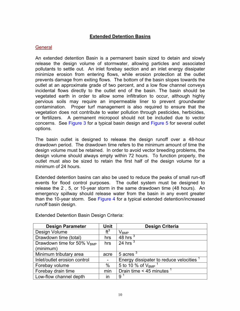
10
Extended Detention Basins
General An extended detention Basin is a permanent basin sized to detain and slowly release the design volume of stormwater, allowing particles and associated pollutants to settle out. An inlet forebay section and an inlet energy dissipater minimize erosion from entering flows, while erosion protection at the outlet prevents damage from exiting flows. The bottom of the basin slopes towards the outlet at an approximate grade of two percent, and a low flow channel conveys incidental flows directly to the outlet end of the basin. The basin should be vegetated earth in order to allow some infiltration to occur, although highly pervious soils may require an impermeable liner to prevent groundwater contamination. Proper turf management is also required to ensure that the vegetation does not contribute to water pollution through pesticides, herbicides, or fertilizers. A permanent micropool should not be included due to vector concerns. See Figure 3 for a typical basin design and Figure 5 for several outlet options. The basin outlet is designed to release the design runoff over a 48-hour drawdown period. The drawdown time refers to the minimum amount of time the design volume must be retained. In order to avoid vector breeding problems, the design volume should always empty within 72 hours. To function properly, the outlet must also be sized to retain the first half of the design volume for a minimum of 24 hours. Extended detention basins can also be used to reduce the peaks of small run-off events for flood control purposes. The outlet system must be designed to release the 2 , 5, or 10-year storm in the same drawdown time (48 hours). An emergency spillway should release water from the basin in any event greater than the 10-year storm. See Figure 4 for a typical extended detention/increased runoff basin design. Extended Detention Basin Design Criteria:
Design Parameter Unit Design Criteria Design Volume ft3 VBMP Drawdown time (total) hrs 48 hrs 3 Drawdown time for 50% VBMP (minimum)
hrs 24 hrs 3
Minimum tributary area acre 5 acres 3 Inlet/outlet erosion control - Energy dissipater to reduce velocities 1 Forebay volume % 5 to 10 % of VBMP 1 Forebay drain time min Drain time < 45 minutes 1 Low-flow channel depth in 9 1

11
Low-flow chan. flow capacity - 2 times the forebay outlet rate 1 Bottom slope of upper stage % 2.0 1 Length to width ratio (min.) - 2:1 (larger preferred) 1 Upper stage depth/width (min.)
ft 2’ depth / 30’ width 1
Bottom stage volume % 10 to 25 % of VBMP 1 Bottom stage depth ft 1.5 to 3 ft deeper than top stage 1 Freeboard (minimum) ft 1.0 1 Embankment side slope (H:V)
- ≥ 2:1 inside / ≥ 4:1 outside (w/o retaining walls) 1
Maintenance access ramp slope
% 10 % or flatter 1
Maintenance access ramp width
ft 15’ – approach paved with asphalt concrete 1
1. Ventura County’s Technical Guidance Manual for Stormwater Quality Control Measures 2. City of Modesto’s Guidance Manual for New Development Stormwater Quality Control Measures 3. CA Stormwater BMP Handbook for New Development and Significant Redevelopment 4. Riverside County DAMP Supplement A Attachment Extended Detention Basin Design Procedure 1. Design Volume
Use Worksheet 1- Design Procedure Form for Design Volume, VBMP. 1. Basin Shape
Whenever possible, shape the basin with a gradual expansion from the inlet toward the middle and a gradual contraction from middle toward the outlet. The length to width ratio should be a minimum of 2:1. Internal baffling with berms may be necessary to achieve this ratio.
2. Two-Stage Design Whenever feasible, provide a two-stage design with a pool that fills often with frequently occurring runoff. This minimizes standing water and sediment deposition in the remainder of the basin. a. Upper stage: The upper stage should be a minimum of 2 feet deep with
the bottom sloped at 2 percent toward the low flow channel. Minimum width of the upper stage should be 30 feet.
b. Bottom stage: The active storage basin of the bottom stage should be 1.5
to 3 feet deeper than the top stage and store 10 to 25 percent of the design volume.
3. Forebay Design
The forebay provides a location for sedimentation of larger particles that has a solid bottom surface to facilitate mechanical removal of accumulated

12
sediment. The forebay volume should be 5 to 10 percent of the VBMP. A berm should separate the forebay from the upper stage of the basin. The outlet pipe from the forebay to the low-flow channel should be sized to drain the forebay volume in 45 minutes. The outlet pipe entrance should be offset from the forebay inlet to prevent short circuiting.
4. Low-flow Channel
The low flow channel conveys flow from the forebay to the bottom stage. Erosion protection should be provided where the low-flow channel enters the bottom stage. Lining of the low flow channel with concrete is recommended. The depth of the channel should be at least 9 inches. The flow capacity of the channel should be twice the release capacity of the forebay outlet.
5. Trash Rack/Gravel Pack A trash rack or gravel pack around perforated risers shall be provided to protect outlet orifices from clogging. Trash racks are better suited for use with perforated vertical plates for outlet control and allow easier access to outlet orifices for purposes of inspection and cleaning. Trash rack shall be sized to prevent clogging of the primary water quality outlet without restricting the hydraulic capacity of the outlet control orifices.
6. Basin Outlet The basin outlet should be sized to release the design volume, VBMP over a 48-hour period, with no more than 50 percent released in 24 hours. The outflow structure should have a trash rack or other acceptable means to prevent clogging, and a valve that can stop discharge from being released in case of an accidental spill in the watershed (Figure 5). The discharge through a control orifice can be calculated using the following steps: a. Develop a Stage vs. Discharge curve for the outlet structure b. For example: If using an orifice, select the orifice size and use the
following equation to develop a Stage vs. Discharge relationship for this outlet: Q = CA[2g(H-Ho)]0.5 Where: Q = discharge (ft3/s) C = orifice coefficient A = area of the orifice (ft) G = gravitational constant (32.2 ft2/s) H = water surface elevation (ft) Ho = orifice elevation (ft)
Recommended values for C are 0.66 for thin material (e.g. CMP riser) and 0.8 when the material is thicker than the orifice diameter (e.g. concrete

13
riser). Alternative non-mechanical hydraulic control structures are acceptable (e.g. weirs, risers, etc).
c. Develop a Stage vs. Volume curve for the basin
Based on the shape and size of the basin, develop a relationship between the stage and the volume of water in the basin.
d. Create an Inflow Hydrograph
Create an inflow hydrograph that delivers the design volume VBMP instantaneously to the basin. This can be approximated by creating a hydrograph with two 5-minute intervals that together convey the entire VBMP.
e. Route the Volume through the Basin
Route the volume of water through the basin using these curves. If this meets the hydraulic retention time requirements (50% of the volume empties in not less than 24 hours, 100% of the volume empties in not less than 48 hours and not more than 72 hours) the outlet is correctly sized. If these requirements are not met, select a new outlet size or configuration and repeat the process.
7. Inlet/Outlet Design Basin inlet and outlet points should be provided with an energy dissipation structure and/or erosion protection.
8. Turf Management Basin vegetation provides erosion protection and improves sediment entrapment. Basin bottoms, berms, and side slopes may be planted with native grasses or with irrigated turf. Several BMPs must be implemented to ensure that this vegetation does not contribute to water pollution through pesticides, herbicides, or fertilizers. These BMPs shall include, at a minimum: (1) educational activities, permits, certifications, and other measures for local applicators and distributors; (2) integrated pest management measures that rely on non-chemical solutions; (3) the use of native vegetation; (4) schedules for irrigation and chemical application; and (5) the collection and proper disposal of unused pesticides, herbicides, and fertilizers.
9. Embankment
Embankment designs must conform to requirements of the State of California Division of Safety of Dams, if the basin dimensions cause it to fall under that agency’s jurisdiction. Interior slopes should be no steeper than 2:1 and exterior slopes no steeper than 4:1. Flatter slopes are preferable. Embankment fill is discouraged and should never be higher than three feet unless the basin is to be publicly maintained.

14
10. Access All-weather access to the bottom, forebay, and outlet works shall be provided for maintenance vehicles. Maximum grades of access ramps should be 10 percent and minimum width should be 15 feet.
11. Bypass
Provide for bypass or overflow of runoff volumes in excess of the design volume. Spillway and overflow structures should be designed in accordance with applicable standards of the Riverside County Flood Control District.
12. Geotextile Fabric
Non-woven geotextile fabric used in conjunction with gravel packs around perforated risers shall conform with the specifications located in Table 3.
Table 3. Non-woven Geotextile Fabric Specifications
Property Test Reference Minimum Specification
Grab Strength ASTM D4632 90 lbs Elongation at peak load ASTM D4632 50 % Puncture Strength ASTM D3787 45 lbs Permitivity ASTM D4491 0.7 sec-1 Burst Strength ASTM D3786 180 psi Toughness % Elongation x Grab
Strength 5,500 lbs
Ultraviolet Resistance (% strength retained at 500 Weatherometer hours)
ASTM D4355 70 %

15
Worksheet 3
Design Procedure Form for Extended Detention Basin Designer:__________________________________________________________ Company:_________________________________________________________ Date:_____________________________________________________________ Project:___________________________________________________________ Location:__________________________________________________________ 1. Determine Design Volume (Use
Worksheet 1) a. Total Tributary Area (minimum 5
ac.) b. Design Volume, VBMP
Atotal = __________ acres VBMP = __________ ft3
2. Basin Length to Width Ratio (2:1 min.)
Ratio = __________ L:W
3. Two-Stage Design
a. Overall Design 1) Depth (3.5’ min.) 2) Width (30’ min.) 3) Length (60’ min.) 4) Volume (must be ≥ VBMP)
b. Upper Stage 1) Depth (2’ min.) 2) Bottom Slope (2% to low flow
channel recommended) c. Bottom Stage
1) Depth (1.5’ to 3’) 2) Length 3) Volume (10 to 25% of VBMP)
Depth = __________ ft Width = __________ ft Length = __________ ft Volume = __________ ft3 Depth = __________ ft Slope = __________ % Depth = __________ ft Length = __________ ft Volume = __________ ft3
4. Forebay Design
a. Forebay Volume (5 to 10% of VBMP) b. Outlet pipe drainage time (≅ 45
min)
Volume = __________ ft3 Drain time = __________ minutes
5. Low-flow Channel
a. Depth (9” minimum) b. Flow Capacity (2 * Forebay QOUT)
Depth = _________ ft QLow Flow = _________ cfs
6. Trash Rack or Gravel Pack (check one)
Trash Rack ______ Gravel Pack ______

16
7. Basin Outlet
a. Outlet type (check one)
b. Orifice Area c. Orifice Type d. Maximum Depth of water above
bottom orifice e. Length of time for 50% VBMP
drainage (24 hour minimum) f. Length of time for 100% VBMP
drainage (between 48 and 72 hours)
g. Attached Documents (all required) 1) Stage vs. Discharge 2) Stage vs. Volume 3) Inflow Hydrograph 4) Basin Routing
Single orifice _____ Multi-orifice plate _____ Perforated Pipe _____ Other ___________________ Area = __________ ft2 Type ______________________ Depth = __________ ft Time 50% = __________ hrs Time 100% = __________ hrs Attached Documents (check) 1) __________
2) __________ 3) __________ 4) __________
8. Increased Runoff (optional)
Is this basin also mitigating increased runoff? Attached Documents (all required) for 2, 5, & 10-year storms:
1) Stage vs. Discharge 2) Stage vs. Volume 3) Inflow Hydrograph 4) Basin Routing
Yes ______ No ______ (if No, skip to #9) Attached Documents (check) 1) __________
2) __________ 3) __________ 4) __________
9. Vegetation (check type)
____ Native Grasses ____ Irrigated Turf ____ Other ___________________________
10. Embankment
a. Interior slope (4:1 max.) b. Exterior slope (3:1 max.)
Interior Slope = _________ % Exterior Slope = _________ %
11. Access
a. Slope (10% max.) b. Width (16 feet min.)
Slope = __________ % Width = __________ ft

17
Notes:

18
Figure 3: EXTENDED DETENTION BASIN
Source: Ventura County Guidance Manual

19
Figure 4: EXTENDED DETENTION / INCREASED RUNOFF BASIN
Source: CA BMP Handbook (2003)

20
Figure 5: EXTENDED DETENTION BASIN TYPICAL OUTLETS
Source: Ventura County Guidance Manual

21
Infiltration Basins General An infiltration Basin is an earthen basin designed to capture the design volume of runoff and infiltrate that stormwater back into the pervious natural surrounding soil. These basins have only an emergency spillway, not a standard outlet, although a relief underdrain will drain the basin if standing water conditions occur. Flows that exceed the design volume should be diverted around the infiltration basin. The basin is designed to retain the design volume and allow it to percolate into the underlying soil over a period of 48 hours, which removes soluble and fine particulate pollutants. Sediment clogging can be avoided by including a settling basin near the inlet as well as the required energy dissipater. The sides and bottom of the basin include vegetation to protect the basin from erosion. Infiltration basins typically treat developments up to 50 acres in size. Infiltration Basin Design Criteria:
Design Parameter Unit Design Criteria Design Volume ft3 VBMP Drawdown time hrs 48 hrs 3 Maximum Tributary Area acre 50 acres 4 Minimum Infiltration Rate in/hr 0.5 in/hr 4 Bottom Basin elevation ft 5 feet or more above seasonally high
groundwater table 1 Minimum Freeboard ft 1.0 ft 1 Setbacks ft
100 feet from wells, tanks, fields, springs 1 20 feet down slope of 100 feet up slope from foundations 1
Inlet/outlet erosion control - Energy dissipater to reduce inlet/outlet velocity 1
Embankment side slope (H:V)
-
4:1 or flatter inside slope/ 3:1 or flatter outside slope (without retaining walls) 1
Maintenance access ramp slope (H:V)
- 10:1 or flatter 1
Maintenance access ramp width
ft 16.0 – approach paved with asphalt concrete1
Vegetation - Side slopes and bottom (may require irrigation during summer) 1
Relief Underdrain - A perforated PVC pipe with valve is to be installed to serve as a relief drain in the event of system failure. 2
1 Ventura County’s Technical Guidance Manual for Stormwater Quality Control Measures 2 City of Modesto’s Guidance Manual for New Development Stormwater Quality Control Measures 3 CA Stormwater BMP Handbook for New Development and Significant Redevelopment 4 Riverside County DAMP Supplement A Attachment

22
Infiltration Basin Design Procedure 1. Design Storage Volume
Use Worksheet 1- Design Procedure Form for Design Storage Volume, VBMP.
2. Basin Surface Area Calculate the minimum surface area: Am = VBMP / Dm Where Am = minimum area required (ft2) VBMP = volume of the infiltration basin (ft3) Dm = maximum allowable depth (ft) Dm= [(t) x (I)] / 12s
Where I = site infiltration rate (in/hr) s = safety factor t = minimum drawdown time (48 hours) In the formula for maximum allowable depth, the safety factor accounts for the possibility of inaccuracy in the infiltration rate measurement. The less certain the infiltration rate the higher the safety factor shall be. Minimum safety factors shall be as follows:
• Without site-specific borings and percolation tests, use s = 10 • With borings (but no percolation test), use s = 6 • With percolation test (but no borings), use s = 5 • With borings and percolation test, use s = 3
3. Inline/Offline
Basins may be on-line or off-line with flood control facilities. For on-line basins, the water quality outlet may be superimposed on the flood control outlet or may be constructed as a separate outlet.
4. Basin Inlet
The inlet structure should dissipate energy of incoming flow to avoid scouring of the basin. If high sediment loads are anticipated a settling basin with a volume of 10 to 20 percent of the design volume should be placed at the inlet of the basin.
5. Vegetation
Bottom vegetation provides erosion protection and sediment entrapment. Basin bottoms, berms, and side slopes may be planted with native grasses or with irrigated turf.

23
6. Embankments
Design embankments to conform to requirements of State of California Division of Safety of Dams, if the basin dimensions cause it to fall under that agency’s jurisdiction. Interior slopes should be no steeper than 4:1 and exterior slopes no steeper than 3:1. Flatter slopes are preferable.
7. Access
All-weather access to the bottom, forebay, and outlet works shall be provided for maintenance vehicles. Maximum grades of access ramps should be 10 percent and minimum width should be 16 feet. Ramps should be paved with concrete. Provide security fencing, except when used as a recreation area.
8. Bypass
Provide for bypass or overflow of runoff volumes in excess of the design volume. Spillway and overflow structures should be designed in accordance with applicable standards of the Riverside County Flood Control District.
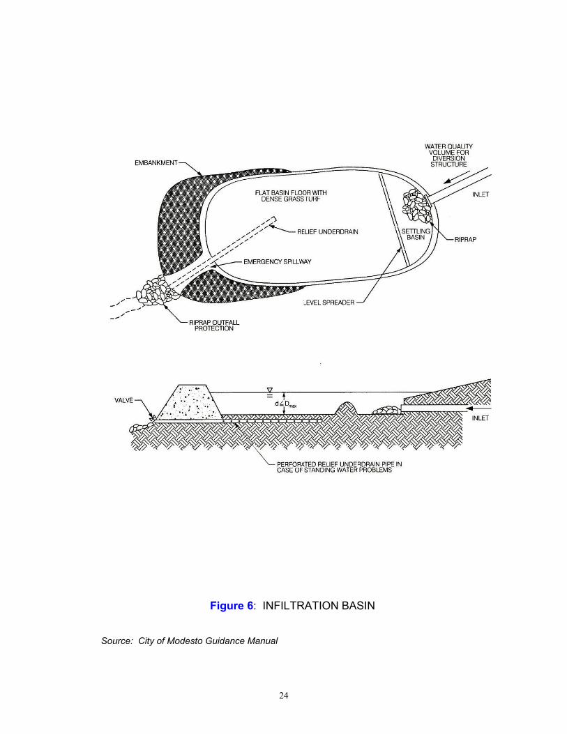
24
Figure 6: INFILTRATION BASIN
Source: City of Modesto Guidance Manual

25
Worksheet 4 Design Procedure Form for Infiltration Basin Designer:__________________________________________________________ Company:_________________________________________________________ Date:_____________________________________________________________ Project:___________________________________________________________ Location:__________________________________________________________ 1. Determine Design Storage Volume
(Use Worksheet 1) a. Total Tributary Area (maximum 50) b. Design Storage Volume, VBMP
Atotal = __________ acres VBMP = __________ ft3
2. Maximum Allowable Depth (Dm)
a. Site infiltration rate (I) b. Minimum drawdown time (48 hrs) c. Safety factor (s) d. Dm = [(t) x (I)]/[12s]
I = __________ in/hr t = __________ hrs s = __________ Dm = __________ ft
3. Basin Surface Area Am = VBMP / Dm
Am = _________ ft2
4. Vegetation (check type used or
describe “other”)
____ Native Grasses ____ Irrigated Turf Grass ____ Other ________________________________________________________________
Notes:

26
Infiltration Trenches General An infiltration trench is an excavated trench that has been refilled with a gravel and sand bed capable of holding the design volume of stormwater runoff. The runoff is stored in the trench over a period of time (48 hours) during which it slowly infiltrates back into the naturally pervious surrounding soil. This infiltration process effectively removes soluble and particulate pollutants, however it is not intended to trap course sediments. It is recommended that an upstream control measure such as a grass swale or filter strip be combined with an infiltration trench to remove sediments that might clog the trench. These trenches also include a bypass system for volumes greater than the design capture volume, and a perforated pipe as an observation well to monitor water depth. An infiltration trench can typically treat developments up to 10 acres. Infiltration Trench Design Criteria
Design Parameter Unit Design Criteria Design Volume ft3 VBMP Drawdown time hrs 48 hrs 3 Maximum Tributary Area acre 10 acres 2 & 3 Minimum Infiltration Rate of Soil
in/hr 0.27 in/hr 4
Trench bottom elevation ft 5 feet or more above seasonally high groundwater table 1
Maximum Trench depth (Dm)
ft 8.0 ft 1
Gravel bed material ft Clean, washed aggregate 1 to 3 inches in diameter 1
Trench lining material - Geotextile fabric 1 or 6” layer of sand 4 Setbacks ft
100 feet from wells, tanks, fields, or springs 1 20 feet down slope or 100 feet up slope from foundations 1 Do not locate under tree drip-lines 1
1 Ventura County’s Technical Guidance Manual for Stormwater Quality Control Measures 2 City of Modesto’s Guidance Manual for New Development Stormwater Quality Control Measures 3 CA Stormwater BMP Handbook for New Development and Significant Redevelopment 4 Riverside County DAMP Supplement A Attachment

27
Infiltration Trench Design Procedure 1. Design Storage Volume
Use Worksheet 1- Design Procedure Form for Design Storage Volume, VBMP.
2. Trench Water Depth Calculate the maximum allowable depth of water in the trench, Dm, in feet. Maximum depth should not exceed 8 feet: Dm = [(t) x (I)] / (12s) Where I = site infiltration rate (in/hr) s = safety factor t = minimum drawdown time (48 hours) In the formula for maximum allowable depth, the safety factor accounts for the possibility of inaccuracy in the infiltration rate measurement. The less certain the infiltration rate, the higher the safety factor should be. Minimum safety factors shall be as follows:
• Without site-specific borings and percolation tests, use s = 10 • With borings (but no percolation test), use s = 6 • With percolation test (but no borings), use s = 5 • With borings and percolation test, use s = 3
3. Trench Surface Area
Calculate the minimum surface area of the trench bottom: Am = VBMP / Dm Where Am = minimum area required (ft2)
VBMP = Detention Volume (ft3) Dm = maximum allowable depth (ft)
4. Observation Well
Provide a vertical section of perforated PVC pipe, 4 to 6 inches in diameter, installed flush with top of trench on a foot-plate and with a locking, removable cap.
5. Bypass
Provide for bypass or overflow of runoff volumes in excess of the SQDV by means of a screened overflow pipe connected to downstream storm drainage or grated overflow outlet.

28
Figure 7: INFILTRATION TRENCH
Source: Ventura County Guidance Manual

29
Worksheet 5 Design Procedure Form for Infiltration Trench Designer:__________________________________________________________ Company:_________________________________________________________ Date:_____________________________________________________________ Project:___________________________________________________________ Location:__________________________________________________________ 1. Determine Design Storage Volume
(Use worksheet 1) a. Total Tributary Area (maximum 10) b. Design Storage Volume, VBMP
Atotal = __________ acres VBMP = __________ ft3
2. Maximum Allowable Depth (Dm =
tl/12s) a. Site infiltration rate (I) b. Minimum drawdown time (t = 48
hrs) c. Safety factor (s) d. Dm = tl/12s
I = __________ in/hr t = __________ hrs s = __________ Dm = __________ ft
3. Trench Bottom Surface Area Am = VBMP / Dm
Am = _________ ft2
Notes:

30
Porous Pavement General Porous Pavement is an infiltration BMP that consists of porous pavement blocks placed over a shallow recharge bed of sand and gravel. It is typically restricted to low volume parking areas that do not receive significant offsite runoff. The modular pavement blocks allow water to seep into the recharge bed, where the sand and gravel layers percolate the design volume into the natural surrounding soils. Porous Pavement can be used for areas of up to 10 acres. Porous Pavement Design Criteria:
Design Parameter Unit Design Criteria Design Volume ft3 VBMP Drawdown Time hrs 12 hours 1 Maximum Tributary Area acre 10 acres 2,4 Maximum contributing area slope
% 5 % 2,4
Traffic Use - Locate in areas of low intensity traffic use 2,4
Erosion - Avoid areas of high wind erosion 2 Placement - Do not locate in narrow strips between
areas of impervious pavement 2 Land use - Do not use in high-risk land uses, i.e.
service/gas stations, truck stops, heavy industrial sites 2
Sediment - Sediment-laden runoff must be directed away from the porous pavement/recharge bed. Place filter fabric on the floor and sides of the recharge bed. 2
Modular Porous Block Type
% 40% surface area open 1
Porous Pavement Infill - ASTM C-33 Sand or equivalent 1 Base Course inches 1” sand (ASTM C-33) over 9” gravel 1 Perimeter Wall Width inches 6 inches 1
1 Ventura County’s Technical Guidance Manual for Stormwater Quality Control Measures 2 City of Modesto’s Guidance Manual for New Development Stormwater Quality Control Measures 3 CA Stormwater BMP Handbook for New Development and Significant Redevelopment 4 Riverside County DAMP Supplement A Attachment

31
Porous Pavement Design Procedure 1. Design Storage Volume
Use Worksheet 1- Design Procedure Form for Design Storage Volume, VBMP.
2. Basin Surface Area Calculate minimum required surface area, Am, based on surcharge depth of 2 inches as follows:
Am = VBMP / 0.17 ft 3. Select Block Type
Select appropriate modular blocks that have no less than 40 percent of the surface area open. The manufacturer’s installation requirements shall be followed with the exception of the infill material and base dimensions, which will meet the criteria listed in this manual.
4. Porous Pavement Infill
The pavement block openings should be filled with ASTM C-33 graded sand (fine concrete aggregate, not sandy loam turf).
5. Base Courses
Provide a 1-inch thick sand base course over a 9-inch thick gravel base course.
6. Perimeter Wall
Provide a concrete perimeter wall to confine the edges of the pavement area. The wall should be minimum 6-inch wide and at least 6 inches deeper than all the porous media and modular block depth combined.
7. Sub-base
If expansive soils or rock are a concern or the tributary catchment has chemical or petroleum products handled or stored, install an impermeable membrane below the base course. Otherwise install a non-woven geotextile membrane to encourage filtration.
8. Overflow
Provide an overflow, possibly with an inlet to a storm sewer, set at 2 inches above the level of the porous pavement surface. Make sure the 2-inch ponding depth is contained and does not flow out of the area at ends or sides.

32
Figure 8: Porous Pavement Detention
Source: Ventura County Guidance Manual

33
Worksheet 6 Design Procedure Form for Porous Pavement Designer:__________________________________________________________ Company:_________________________________________________________ Date:_____________________________________________________________ Project:___________________________________________________________ Location:__________________________________________________________ 1. Determine Design Storage Volume
(Use Worksheet 1) a. Total Tributary Area (maximum 10) b. Design Storage Volume, VBMP
Atotal = __________ acres VBMP = __________ ft3
2. Basin Surface Area
a. Detention Volume VBMP b. Am = VBMP / (0.17 ft)
VBMP = __________ ft3 Am = __________ ft2
3. Block Type
a. Minimum open area = 40% b. Minimum thickness = 4 inches
Block Name = ________________
Manufacturer = ________________ Open Area = __________ % Thickness = __________ inches
4. Base Course
a. ASTM C33 Sand Layer (1 inch) b. ASSHTO M43-No.8 Gravel Layer
(9 inches)
Sand Layer _______ (check) Gravel Layer _______ (check)
Notes:

34
Sand Filters General Sand Filters capture and treat the design runoff in a two-part system, first a settling basin, then a filter bed. The settling basin collects large sediment and prevents these particles from clogging the filter bed. The sand bed then strains the water, removing soluble and particulate pollutants. The treated water is conveyed through pipes back into a stream or channel. Sand Filters are especially useful where water quality concerns might preclude the use of infiltration BMPs. There are many variations of sand filter designs, and it is up to the designer to determine the most effective sand filter to use in each case. Two of the most common sand filters, the Austin sand filter and the Delaware sand filter, have been conditioned in this manual. Although the Austin filter was not included in the Attachment, it was added to this manual because it can treat a very large tributary area and because it is well suited to southern California. Other sand filter designs may be used if it is shown that they are more appropriate. Austin Sand Filter The Austin Sand Filter, as developed by the city of Austin, Texas, is an aboveground sand filter that does not include a permanent wet pool. The filter inlet captures the design volume, while directing larger flows past. The first chamber of the filter is the sedimentation basin, which holds the entire design volume (this handbook conditions a full sedimentation design). The design volume drains into the second chamber, which is the filtration basin, over a period of 48 hours. This allows large particles to settle in the sedimentation basin and protects the filter bed from clogging. The sand and gravel filter bed removes soluble and particulate pollutants, and the treated water is returned to a storm drain. In order to drain by gravity, an Austin sand filter must be located in an area where the topography has sufficient vertical drops. These filters can be used to treat runoff from areas up to 100 acres large.

35
Austin Sand Filter Basin Design Criteria:
Design Parameter Unit Design Criteria Design Volume ft3 VBMP Maximum tributary area acre 1001 Minimum sedimentation basin depth ft 3 1 Minimum sedimentation basin area (As)
ft2 VBMP / 10 ft 1
Length to Width ratio (L:W) - 2 to 1 or greater1 Draw-down time hrs 48 3 Freeboard ft 1.0 ft above maximum water
surface elevation 1 Minimum sedimentation basin volume ft3 VBMP + freeboard volume 1 Maximum inlet velocity fps 3.0 1 Minimum particle size removed micron 20 (specific gravity =2.65) 1 Minimum gravel depth over sand filter inches 2 1 Maximum water depth over filter, 2h ft Between 2 and 10 feet 3 Minimum sand depth, ds inches 18 1 Minimum filtration rate of filter, k ft/d 3.5 1 Slope of sand filter surface % 0 1 Minimum gravel cover over underdrain inches 2 1 Sand size, diameter inches 0.02 – 0.04 1 Underdrain gravel diameter size inches 0.5 – 2.0 1 Minimum inside diameter underdrain inches 6 1 Underdrain pipe type - PVC schedule 40 (or thicker) 1 Minimum slope of underdrain % 1.0 1 Minimum underdrain perforation diameter
inches 0.375 1
Minimum perforations per row - 6 1 Minimum space between perforation rows
inches 6 1
Minimum gravel bed depth, dg inches 16 1 1 Ventura County’s Technical Guidance Manual for Stormwater Quality Control Measures 2 City of Modesto’s Guidance Manual for New Development Stormwater Quality Control Measures 3 CA Stormwater BMP Handbook for New Development and Significant Redevelopment 4 Riverside County DAMP Supplement A Attachment

36
Austin Sand Filter Design Procedure Part I – Sedimentation Basin Design 1. Design Storage Volume
Use Worksheet 1- Design Procedure Form for Design Storage Volume, VBMP.
2. Maximum Water Depth Determine maximum allowable depth of water (2h) in the sedimentation basin considering elevation differences between inlet and outlet inverts of the sedimentation basin and filter surface. (This sets the height or elevation of the inlet invert for bypass pipes and orifices).
3. Sedimentation Basin Design
The sedimentation basin design should maximize the distance from the inlet to the outlet while avoiding short circuiting (flow reaching the outlet structure before it passes through the sedimentation basin volume) and dead storage areas (areas in the basin that are bypassed by the main flow). The basin shape should include a gradual expansion from the inlet and a gradual contraction toward the outlet. The length to width ratio should be a minimum of 2:1. Internal baffling with berms may be necessary to achieve this ratio. a. Find the sedimentation basin area, As
As = VBMP / (2h) b. Determine the basin length and width
Width = As / (3) Length = (2) x (width)
4. Energy Dissipation Structure
Basin inlet and outlet points should include an energy dissipation structure and/or erosion protection. An energy dissipation structure is required when inlet velocities exceed 3 feet per second.
5. Sedimentation Inlet The inlet structure design must isolate the water quality volume and convey flows greater than the VBMP past the basin. The water quality volume should be discharged uniformly and at low velocities into the sedimentation basin.
6. Sedimentation Outlet
The outlet structure conveys the water quality volume from the sedimentation basin to the filtration basin. The outlet structure shall be designed to outlet the design volume (ponded to a height of 2h) into the filter basin over a drawdown period of 48 hours.
7. Trash Rack/Gravel Pack A trash rack or gravel pack around perforated risers shall be provided to protect outlet orifices from clogging.

37
8. Sediment Trap (optional)
Placing a sediment trap in the basin can improve long-term removal efficiency and reduce maintenance requirements.
Part II – Filter Basin Design 9. Filter Basin Surface Area
The required filter basin surface area (Af) can be calculated using the following simplified equation from the CA BMP Handbook: Af = VBMP / 18
10. Filter Basin Volume The storage capacity of the filtration basin, above the surface of the filter media, should be greater than or equal to 20 percent of the VBMP. This capacity is necessary in order to account for backwater effects resulting from partially clogged filter media. If the filter basin volume is less than the required volume, redesign with an increased filter depth or increase the filter area.
11. Filter Basin Inlet Structure
The inlet structure should spread the flow uniformly across the surface of the media filter. Flow spreaders, weirs or multiple orifice openings are recommended.
12. Filter Bed
The sand bed may be a choice of one of the two configurations given below. Note: Sand bed depths are final, consolidated depths. Consolidated effects must be taken into account.
1) Sand Bed with Gravel Layer (Figure 9A)
The sand layer is a minimum depth of 18 inches consisting of 0.02-0.04 inch diameter sand. Under the sand is a layer of 0.5 to 2.0 inch diameter gravel which provides a minimum of two inches of cover over the top of the underdrain lateral pipes. No gravel is required under the lateral pipes. A layer of geotextile fabric meeting the following specifications must separate the sand and gravel and must be wrapped around the lateral pipes:
Table 4. Geotextile Fabric Specifications
Property Test Method Unit Specification Material Nonwoven
geotextile fabric Unit Weight Oz/yd2 8 (minimum)

38
Filtration Rate In/sec 0.08 (minimum) Puncture Strength ASTM D-751
(modified) Lb. 125 (minimum)
Mullen Burst Strength
ASTM D-751 PSI 400 (minimum)
Tensile Strength ASTM-D-1682 Lb. 300 (minimum) Equiv. Opening Size US Standard Sieve No. 80 (minimum)
Drainage matting meeting the following specifications should be placed under the laterals to provide for adequate vertical and horizontal hydraulic conductivity to the laterals:
Table 5. Drainage Matting Specifications
Property Test Method Unit Specification Material Nonwoven
geotextile fabric Unit Weight Oz/yd2 20 Flow Rate (fabric) GPM/ft2 180 (minimum) Permeability ASTM D-2434 Cm/sec 12.4 x 10⁻² Grab strength (fabric) ASTM D-1682 Lb. Dry Lg. 90 Dry Wd.
70 Wet Lg. 95 Wet Wd. 70
Puncture Strength (fabric)
COE CW-02215
Lb. 42 (minimum)
Mullen burst strength ASTM D-1117 Psi 140 (minimum) Equiv. opening size US Standard
Sieve No. 100 (70 – 120)
Flow rate (drainage core)
Drexel Univ. Test Method
GPM/ft. width
14
In areas with high sediment load (total suspended solids concentration ≥ 200 mg/L), the two-inch layer of stone on top of the sand filter should be underlain with Enkadrain 9120 filter fabric or equivalent with the following specifications:
Table 6. Filter Fabric Specifications
Property Test Method Unit Specification Material Nonwoven
geotextile fabric Unit Weight ASTM D-1777 Oz/yd2 4.3 (minimum) Flow Rate Failing Head Test GPM/ft2 120 (minimum) Puncture Strength
ASTM-D751 (modified) Lb. 60 (minimum)
Thickness inches 0.8 (minimum)

39
2) Sand Bed with Trench Design (Figure 9B) The top layer shall be 12-18 inches of 0.02-0.04 inch diameter sand. Laterals shall be placed in trenches with a covering of 0.5 to 2.0-inch gravel and geotextile fabric. The laterals shall be underlain by a layer of drainage matting. The geotextile fabric is needed to prevent the filter media from infiltrating into the lateral piping. The drainage matting is needed to provide for adequate vertical and horizontal hydraulic conductivity to the laterals. The geotextile fabric and drainage matting specifications are listed above in Tables 1 and 2 respectively. A minimum 2” layer of stone will be place on top of the sand bed underlain with filter fabric (Table 4) in drainage areas with high sediment loads (TSS ≥ 200 mg/L).
13. Underdrain Piping
The underdrain piping consists of the main collector pipe(s) and perforated lateral branch pipes. The piping should be reinforced to withstand the weight of the overburden. Internal diameters of lateral branch pipes should be six inches or greater and perforations should be 3/8 inch. Each row of perforations should contain at least six holes and the maximum spacing between rows of perforations should not exceed six inches. All piping is to be schedule 40 polyvinyl chloride or greater strength. The minimum grade of piping shall be 1 percent slope (slopes down to 0.5% are acceptable with prior approval). Access for cleaning all underdrain piping is needed. Note: No draw-down time is to be associated with sand filtration basins, only with sedimentation basins. Thus, it is not necessary to have a specifically designed orifice for the filtration outlet structure.
14. Filter Basin Liner If an impermeable liner is required to protect ground water quality it shall meet the specifications for clay liner given in the following table (table 4). The clay liner should have a minimum thickness of 12 inches. If an impermeable liner is not required then a geotextile fabric liner shall be installed that meets the specifications listed in table 1 unless the pond has been excavated to bedrock. If a geomembrane is used it should have a minimum thickness of 30 mils and be ultraviolet resistant.
Table 7. Clay Liner Specifications
Property Test Method Unit Specification Permeability ASTM D-2434 cm/sec 1x10⁻⁶ Plasticity Index of Clay ASTM D-423 & D-424 % Not less than 15 Liquid Limit of Clay ASTM D-2216 % Not less than 30 Clay Particles Passing ASTM-D422 % Not less than 30 Clay Compaction ASTM-D2216 % 95% of Std.
Proctor Density

40
Figure 9: Austin Sand Filter
Source: Ventura County Guidance Manual

41
Figure 9A: Filter Bed with Gravel Underdrain
Figure 9B: Filter Bed with Trench Underdrain
Source: Ventura County Guidance Manual

42
Worksheet 7 Design Procedure Form for Austin Sand Filter Designer:__________________________________________________________ Company:_________________________________________________________ Date:_____________________________________________________________ Project:___________________________________________________________ Location:__________________________________________________________ 1. Determine Design Storage Volume
(Use Worksheet 1) a. Total Tributary Area (maximum
100) b. Design Storage Volume, VBMP
Atotal = __________ acres VBMP = __________ ft3
2. Maximum Water Height in
Sedimentation Basin* a. Invert elevation at connection to
storm drain system. b. Sand Filter invert elevation
(consider min. grade (1%) from storm drain). Point A, Figure 9.
c. Estimate filter depth or use min. (3’).
d. Top elevation of filter bed. Point B, Figure 9.
e. Surface elevation at BMP inlet. Point C, Figure 9.
f. Determine max. allowable height (2h) of water in the sedimentation basin using the elevation difference between points C and B. (min. 2’, max. 10’) 2h = [(C-B) – 1’ Freeboard]
Elev. Storm Drain = __________ ft Elev. Pt A = __________ ft Filter Depth = __________ ft Elev. Pt B = __________ ft Elev. Pt C = __________ ft 2h = ___________ ft
3. Size Sedimentation Basin
a. Find Sedimentation Basin Area, As As = VBMP / (2h)
b. Determine basin length and width, using a length to width ratio ≥ 2:1 width = As / 3 length = 2 x width
As = _________ ft2 width = _________ ft length = _________ ft
4. Size Filter Basin
a. Determine Filter Basin Area, Af Af = VBMP / 18
Af = _________ ft2

43
b. Determine Filter Basin Volume Vf = Af x filter depth (part 2c)
c. Determine Required Volume, Vr Vr = 0.2 x VBMP
d. Check if Vr ≥ Vf? If no, redesign with an increased filter depth or increase filter area.
Vf = _________ ft3 Vr = _________ ft3 Check Vr ≥ Vf _________
Notes: * Based on these elevations, is there a sufficient elevation drop to allow gravity flow from the outlet of the control measure to the storm drain system? If no, investigate alternative on-site locations for treatment control, consider another treatment control measure more suitable for site conditions, or contact the District to discuss on-site pumping requirements.

44
Delaware Sand Filter General A Delaware sand filter is an underground filter consisting of two parallel concrete trenches divided by a close-spaced wall. Water enters the sedimentation trench through grated covers or a storm drain system. After this permanent pool fills, water overflows through the weir notches at the top of the dividing wall into the filter chamber. This assures that water enters the filter chamber as sheet flow and protects the sand bed from scouring. The permanent pool in the sedimentation chamber is dead storage, which allows heavier sediment to settle out and inhibits resuspension of particles from earlier storms. After passing through the filter bed, water flows into a clearwell area and into the storm drain system. Flows greater than the design volume can enter the sedimentation trench as long as an overflow weir is installed into the clearwell. A Delaware filter can treat tributary areas up to 5 acres. Delaware Sand Filter Basin Design Criteria:
Design Parameter Unit Design Criteria 1 Design Volume ft3 VBMP Maximum tributary area acre 5 Weir height between sedimentation chamber and sand filter
in 2” above sand filter bed
Draw-down time hrs 48 3 Minimum gravel depth over sand in 2 Minimum sand depth, ds in 18 Minimum gravel underdrain depth, dg in 16 Filter Coefficient, k ft/day 2 Top layer and underdrain gravel size in 0.5 to 2-inch diameter
stone Sand size - ASTM C33 concrete
sand Slope of top layer % 0 (horizontal) Minimum slope of underdrain or bottom of filter % 0.5% Minimum size underdrain - 6” PVC schedule 40 Minimum size diameter perforation in 3/8 Minimum number of holes per row - 6 Minimum spacing between rows in 6 Minimum weephole diameter in 3 Minimum spacing between weepholes in 9 (center to center) Sedimentation chamber and sand filter width in 18 to 30
1 Ventura County’s Technical Guidance Manual for Stormwater Quality Control Measures 2 City of Modesto’s Guidance Manual for New Development Stormwater Quality Control Measures 3 CA Stormwater BMP Handbook for New Development and Significant Redevelopment 4 Riverside County DAMP Supplement A Attachment

45
Delaware Sand Filter Design Procedure 1. Design Storage Volume
Use Worksheet 1- Design Procedure Form for Design Storage Volume, VBMP.
2. Maximum Water Depth Determine maximum allowable height (2h) of water that can pond over the filter based on elevation differences between the filter bed top and the BMP inlet. An overflow weir should be designed to allow flows greater than the design volume to pass into the clearwell.
3. Sand Filter/Sediment Chamber Surface Area
The DSF shell must have the capacity to accept and store the design volume. The dimensions are sized to provide a filter area that processes the design volume in the desired time frame (48 hrs). The areas of the sedimentation chamber As and filter bed Af are typically set equal. The required areas are calculated as follows depending on the maximum depth of water above the filter bed: a. If 2h < 2.67 ft Use: As = Af = VBMP / (4.1h + 0.9) b. If 2h > 2.67 ft Use: As = Af = [VBMP x ds] / [k (h + ds) t] where: VBMP = Design Volume ft3 Af = filter bed surface area, ft2 As = sediment chamber surface area, ft2 ds = depth of sand, ft k = filter coefficient 0.0833 ft/hr h = one half of maximum allowable water depth (2h), ft t = 48 hour draw-down time
4. Select sediment chamber and filter width (Ws = Wf)
Site considerations usually dictate the final dimensions of the facility. Sediment chambers and filter chambers are normally 18-30 inches wide. Use of standard grates requires a width of 26 inches.
5. Sediment Chamber and Filter Length
Ls = Lf = Af / Wf Round length up as appropriate and compute adjusted Area
As = Af = Wf x Lf 6. Storage volume in Filter Voids Vv
Vv = Af x 0.4(ds + dg) {assume 40% voids} Where dg = underdrain gravel depth
7. Volume of flow through filter during filling, VQ
VQ = [k x Af x (ds + h) x tv] / [ds]

46
Use tv = 1 hour to fill voids 8. Net Volume Required to be Stored in Chambers Awaiting Filtration Vr
Vr = VBMP – Vv – VQ 9. Available Storage in Chambers Va
Va = 2h(Af + As) If Va ≥ Vr, proceed with design If Va< Vr, adjust width and/or length and repeat steps 3-8.
10. Filter Bed
a. Top Gravel Layer The washed gravel layer at the top of the filter should be two inches thick, composed of stone 0.5 to 2.0 inches in diameter. In areas with high sediment load (TSS concentration >200 mg/L), the two-inch layer of stone on top of the sand filter should be underlain with filter fabric meeting the specifications in table 3.
b. Sand Layer The sand layer should be a minimum depth of 18 inches consisting of ASTM C33 concrete sand. A layer of geotextile fabric meeting the specifications in Table 1 must separate the sand and gravel layer below.
c. Gravel Layer The gravel layer surrounding the collector pipes should be at least 16 inches thick and be composed of 0.5 to 2-inch diameter stone and provide at least two inches of cover over the tops of the drainage pipes.
10. Underdrain Piping
The underdrain piping should follow the same criteria and design as the Austin Sand Filter. Shallow rectangular drain tiles may be fabricated from such materials as fiberglass structural channels, saving several inches of filter depth. Drain tiles should be in two-foot lengths and spaced to provide gaps 1/8-inch less than the smallest gravel sizes on all four sides. Sections of tile may be cast in the dividing wall between the filter and the clearwell to provide shallow outflow orifices.
11. Weep Holes
In addition to the underdrain pipes, weepholes should be installed between the filter chamber and the clearwell to provide relief in case of pipe clogging. The weepholes should be three (3) inches in diameter. Minimum spacing should be nine (9) inches center to center. The openings on the filter side of the dividing wall should be covered to the width of the trench with 12-inch high plastic hardware cloth of ¼ inch mesh or galvanized steel wire, minimum wire diameter 0.03-inch, number 4 mesh hardware cloth anchored firmly to the dividing wall structure and folded a minimum of six (6) inches back under the bottom stone.

47
12. Grates and Covers Grates and cast steel covers are designed to take the same wheel loads as the adjacent pavement. Where possible, use standard grates to reduce costs. Grates and covers should be supported by a galvanized steel perimeter frame.
13. Hoods/Traps
In applications where trapping of hydrocarbons and other floating pollutants is required, large-storm overflow weirs should be equipped with a 10-gauge aluminum hood or commercially available catch basin trap. The hood or trap should extend a minimum of one foot into the permanent pool.
14. Dewatering Drain
A six inch diameter dewatering drain with gate valve is to be installed at the top of the stone/sand filter bed through the partition separating the filter chamber from the clearwell chamber.

48
Figure 10: Delaware Sand Filter
Source: Ventura County Guidance Manual

49
Worksheet 8 Design Procedure Form for Delaware Sand Filter Designer:__________________________________________________________ Company:_________________________________________________________ Date:_____________________________________________________________ Project:___________________________________________________________ Location:__________________________________________________________ 1. Determine Design Storage Volume
(Use Worksheet 1) a. Total Tributary Area (maximum
100) b. Design Storage Volume, VBMP
Atotal = __________ acres VBMP = __________ ft3
2. Maximum Water Height in
Sedimentation Basin* a. Invert elevation at connection to
storm drain system. b. Sand Filter invert elevation
(consider min. grade (1%) from storm drain).
c. Estimate filter depth or use min. (3’).
d. Top elevation of filter bed. e. Surface elevation at BMP inlet. f. Determine max. allowable height
(2h) of water that can pond over the filter using the elevation difference between the filter bed top and the BMP inlet. 2h = [(C-B) – 1’ Freeboard]
Elev. Storm Drain = __________ ft Elev. Filter Bottom = __________ ft Filter Depth = __________ ft Filter bed top elev. (pt B) = ________ ft BMP inlet Elev. (pt C) = ________ ft 2h = __________ ft
3. Minimum Surface Area of the
Chambers If 2h < 2.67 feet (2’-8”) Af = As = VBMP / (4.1h + 0.9) If 2h > 2.67 feet (2’-8”) Af = As = [VBMP x ds] / [k(h+ds)tf] a. Sand bed depth, ds b. Filter Coefficient, k c. Draw-down time, t d. ½ max. allowable water depth over
filter, h e. Sediment Chamber Area As, and
Filter Surface Area Af
ds = _________ ft k = _________ ft/hr
t = _________ hr h = _________ ft As and Af = _________ ft2

50
4. Sediment Chamber and Filter
Dimensions a. Select width (Ws = Wf = 18” to 30”) b. Filter length (Ls = Lf = Afm/Wf) c. Adjusted length (rounded) d. Adjusted area (As = Af = Wf x Lf)
Ws = Wf = _________ ft Ls = Lf = _________ ft Ls = Lf = _________ ft As = Af = _________ ft2
5. System Storage Volume
a. Storage in filter voids (Vv = Af x 0.4(dg +ds)
b. Volume of flow through filter (VQ = k x Af(ds+h) 1hr / ds)
c. Required net storage (Vr = VBMP–Vv–VQ)
d. Available storage (Va = 2h(Af +As)) If Va ≥ Vr, sizing is complete If Va < Vr, repeat steps 4 and 5
Vv = _________ ft3 VQ = _________ ft3 Vr = _________ ft3 Va = _________ ft3
Check Vr ≥ Va _________
Notes: * Based on these elevations, is there a sufficient elevation drop to allow gravity flow from the outlet of the control measure to the storm drain system? If no, investigate alternative on-site locations for treatment control, consider another treatment control measure more suitable for site conditions, or contact the District to discuss on-site pumping requirements.

51
Grassed Swales General A Grass swale is a wide, shallow densely vegetated channel that treats stormwater runoff as it is slowly conveyed into a downstream system. These swales have very shallow slopes in order to allow maximum contact time with the vegetation. The depth of water of the design flow should be less than the height of the vegetation. Contact with vegetation improves water quality by plant uptake of pollutants, removal of sediment, and an increase in infiltration. Overall the effectiveness of a grass swale is limited and it is recommended that they are used in combination with other BMPs. Grass Swale Design Criteria:
Design Parameter Unit Design Criteria Design Flow cfs QBMP Minimum bottom width ft 2 ft 2 Maximum channel side slope
H:V 3:1 2
Minimum slope in flow direction
% 0.2 (provide underdrains for slopes < 0.5) 1
Maximum slope in flow direction
% 2.0 (provide grade-control checks for slopes >2.0) 1
Maximum flow velocity ft/sec 1.0 (based on Manning n = 0.20) 1 Maximum depth of flow inches 3 to 5 (1 inch below top of grass) 1 Minimum contact time minutes 7 1 Minimum length ft Sufficient length to provide minimum
contact time 1 Vegetation - Turf grass or approved equal 1 Grass height inches 4 to 6 (mow to maintain height) 1
1 Ventura County’s Technical Guidance Manual for Stormwater Quality Control Measures 2 City of Modesto’s Guidance Manual for New Development Stormwater Quality Control Measures 3 CA Stormwater BMP Handbook for New Development and Significant Redevelopment 4 Riverside County DAMP Supplement A Attachment
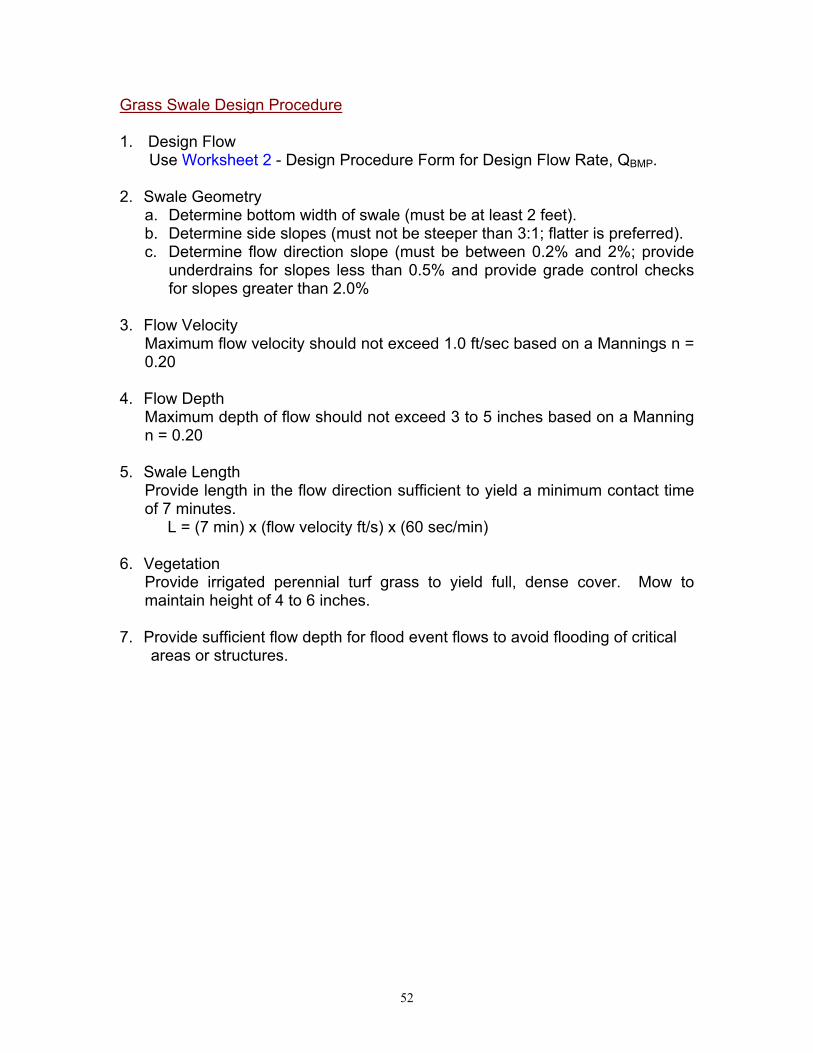
52
Grass Swale Design Procedure
1. Design Flow Use Worksheet 2 - Design Procedure Form for Design Flow Rate, QBMP.
2. Swale Geometry a. Determine bottom width of swale (must be at least 2 feet). b. Determine side slopes (must not be steeper than 3:1; flatter is preferred). c. Determine flow direction slope (must be between 0.2% and 2%; provide
underdrains for slopes less than 0.5% and provide grade control checks for slopes greater than 2.0%
3. Flow Velocity
Maximum flow velocity should not exceed 1.0 ft/sec based on a Mannings n = 0.20
4. Flow Depth Maximum depth of flow should not exceed 3 to 5 inches based on a Manning n = 0.20
5. Swale Length Provide length in the flow direction sufficient to yield a minimum contact time of 7 minutes.
L = (7 min) x (flow velocity ft/s) x (60 sec/min) 6. Vegetation
Provide irrigated perennial turf grass to yield full, dense cover. Mow to maintain height of 4 to 6 inches.
7. Provide sufficient flow depth for flood event flows to avoid flooding of critical areas or structures.

53
Figure 11: Grassed Swale Source: Ventura County Guidance Manual

54
Worksheet 9 Design Procedure Form for Grassed Swale Designer:__________________________________________________________ Company:_________________________________________________________ Date:_____________________________________________________________ Project:___________________________________________________________ Location:__________________________________________________________ 1. Determine Design Flow
(Use Worksheet 2)
QBMP = __________ cfs
2. Swale Geometry
a. Swale bottom width (b) b. Side slope (z) c. Flow direction slope (s)
b = __________ ft z = __________ s = __________ %
3. Design flow velocity (Manning n = 0.2)
v = __________ ft/s
4. Depth of flow (D)
D = __________ ft
5. Design Length (L) L = (7 min) x (flow velocity, ft/sec) x 60
L = __________ ft
6. Vegetation (describe)
8. Outflow Collection (check type used or describe “other”)
___ Grated Inlet’ ___ Infiltration Trench ___ Underdrain ___ Other__________________________
Notes:

55
Filter Strips General Filter Strips are uniformly graded areas of dense vegetation designed to treat sheet flow stormwater runoff. Pollutants are removed by filtering and through settling of sediment and other solid particles as the design flow passes through (not over) the vegetation. Filter strips are usually as wide as the drainage area and must be long enough in the flow direction to adequately treat the runoff. Concentrated flows are redistributed uniformly across the top of the strip with a level spreader. A grass swale, sand filter, or infiltration BMP is recommended in conjunction with a filter strip. Filter Strip Design Criteria:
Design Parameter Unit Design Criteria Design Flow cfs QBMP
1 Maximum linear unit application rate (qa)
cfs/ft x width
0.005 1
Minimum width (normal to flow) ft (QBMP) / (qa) 1 Minimum length (flow direction) ft 15 1 Maximum slope (flow direction) % 4 1 Vegetation - Turf grass (irrigated) or approved
equal 1 Minimum grass height inches 2 1 Maximum grass height inches 4 (typical) or as required to prevent
lodging or shading 1 Level Spreader - A level spreader must be applied
to the flows before reaching the strip 4
Recommendation - This BMP is recommended in conjunction with a grass swale, sand filter, or infiltration BMP 3
1 Ventura County’s Technical Guidance Manual for Stormwater Quality Control Measures 2 City of Modesto’s Guidance Manual for New Development Stormwater Quality Control Measures 3 CA Stormwater BMP Handbook for New Development and Significant Redevelopment 4 Riverside County DAMP Supplement A Attachment

56
Filter Strip Design Procedure
1. Design Flow Use Worksheet 2 - Design Procedure Form for Design Flow Rate, QBMP.
2. Minimum Width Calculate minimum width of the grass strip filter (Wm) normal to flow direction: Wm = (QBMP)/(qa) Wm = (QBMP)/0.005 cfs/ft (minimum)
3. Minimum Length Length of the grass strip filter (Lm) in the direction of flow shall not be less than 15 feet. Lm = 15 feet (minimum)
4. Maximum Slope Slope of the ground in the direction of flow shall not be greater than 4 percent.
5. Flow Distribution Incorporate a device at the upstream end of the filter strip to evenly distribute flows along the top width, such as slotted curbing, modular block porous pavement, or other spreader devices. Concentrated flow delivered to the filter strip must be distributed evenly by means of a level spreader of similar concept.
6. Vegetation Provide irrigated perennial turf grass to yield full, dense cover. Submit a Landscape Plan for stormwater agency review. Plan shall be prepared by a landscape or other appropriate specialist and shall include a site plan showing location and type of vegetation. Mow grass to maintain height approximately between 2 and 4 inches.
7. Outflow Collection Provide a means for outflow collection and conveyance (e.g. grass channel/swale, storm sewer, street gutter).

57
Figure 12: Grass Filter Strip Source: Ventura County Guidance Manual

58
Worksheet 10 Design Procedure Form for Filter Strip Designer:__________________________________________________________ Company:_________________________________________________________ Date:_____________________________________________________________ Project:___________________________________________________________ Location:__________________________________________________________
1. Determine Design Flow (Use Worksheet 2)
QBMP = __________ cfs
2. Design Width
Wm = (QBMP)/0.005 cfs/ft
Wm = __________ ft
3. Design Length (15 ft minimum)
Lm = __________ ft
4. Design Slope (4 % maximum)
SD = __________ %
5. Flow Distribution (check type used or describe “other”)
___ slotted curbing ___ Modular Block Porous Pavement ___ Level Spreader ___other___________________________
6. Vegetation (describe)
5. Outflow Collection (check type used or describe “other”)
___ Grass Swale ___ Street Gutter ___ Storm Drain ___ Underdrain ___ Other__________________________
Notes:

59
Water Quality Inlets General A water quality inlet is a device that removes oil and grit from stormwater runoff before the water enters the stormdrain system. It consists of one or more chambers that promote sedimentation of coarse materials and separation of free oil from stormwater. Manufacturers have created a variety of configurations to accomplish this. A specific model can be selected from the manufactuer based on the design flow rate. A water quality inlet is generally used for pretreatment before discharging into another type of BMP. Water Quality Inlet Design Criteria:
Design Parameter Unit Design Criteria Design Flow cfs QBMP Maximum Tributary Area acres 1 4 Clean-out Schedule - At least twice per year 4
1 Ventura County’s Technical Guidance Manual for Stormwater Quality Control Measures 2 City of Modesto’s Guidance Manual for New Development Stormwater Quality Control Measures 3 CA Stormwater BMP Handbook for New Development and Significant Redevelopment 4 Riverside County DAMP Supplement A Attachment Water Quailty Inlet Design Procedure
1. Design Flow
Use Worksheet 2 - Design Procedure Form for Design Flow Rate, QBMP.
2. Select Model Select a water quality inlet model that will appropriately treat the design flow using manufacturer specifications.
3. Maintenance Requirements
In order to maintain its ability to treat stormwater, the inlet must be cleaned at least twice a year. Arrangements should be made to do this.

60
Worksheet 11 Design Procedure Form for Water Quality Inlets Designer:__________________________________________________________ Company:_________________________________________________________ Date:_____________________________________________________________ Project:___________________________________________________________ Location:__________________________________________________________
1. Determine Design Flow Rate (Use Worksheet 2)
QBMP = __________ cfs
2. Water Quality Inlet
Manufacturer Name Model Flow Capacity of Model Please include a technical sheet from the manufacturer with information on this model.
Make ___________________ Model ___________________ Capacity ____________ cfs
Notes:

61
REFERENCES California Stormwater Quality Association, January 2003. Stormwater Best Management Practice Handbook for New Development and Redevelopment, prepared by Camp Dresser & McKee and Larry Walker Associates City of Modesto, Operations and Maintenance Department, January 2001. Guidance Manual for New Development Stormwater Quality Control Measures Riverside County Drainage Area Management Plans Supplement “A” Attachment, April. Selection and Design of Stormwater Quality Controls, prepared by Riverside County Flood Control and Water Conservation District Ventura Countywide Stormwater Quality Management Program July 2002. Technical Guidance Manual for Stormwater Quality Control Measures

62
APPENDIX A Slope of the Design Volume Curve

63
INSERT
Slope of the Design Volume Curve
HERE

64
APPENDIX B BMP Design Examples
1. Extended Detention Basin
2. Grass Swales

Riverside County Water Quality Management Plan Exhibit E Public Review Draft
April 30, 2004 E-1
Runoff Coefficients for an Intensity = 0.2 inch/hour for Urban Soil Types*
Percent Impervious
A Soil RI = 32
B Soil RI = 56
C Soil RI = 69
D Soil RI = 75
0 (Natural) 0.37 0.59 0.69 0.74 5 0.40 0.61 0.70 0.75 10 0.43 0.62 0.71 0.75 15 0.45 0.64 0.72 0.76 20 (1-Acre) 0.48 0.65 0.73 0.77 25 0.50 0.67 0.74 0.78 30 0.53 0.68 0.75 0.79 35 0.56 0.7 0.76 0.79 40 (1/2-Acre) 0.58 0.71 0.78 0.80 45 0.61 0.73 0.79 0.81 50 (1/4-Acre) 0.64 0.75 0.80 0.82 55 0.66 0.76 0.81 0.83 60 0.69 0.78 0.82 0.84 65 (Condominiums) 0.72 0.79 0.83 0.84 70 0.74 0.81 0.84 0.85 75 (Mobile Homes) 0.77 0.82 0.85 0.86 80 (Apartments) 0.79 0.84 0.86 0.87 85 0.82 0.85 0.87 0.88 90 (Commercial) 0.85 0.87 0.88 0.89 95 0.87 0.88 0.89 0.89 100 0.90 0.9 0.90 0.90
* Complete District’s standards can be found in the Riverside County Flood Control – Hydrology Manual

Riverside County Water Quality Management Plan Exhibit F Public Review Draft
April 30, 2004 F-1
Best Management Practices (BMPs) – Defined in 40 CFR 122.2 as schedules of activities, prohibitions of practices, maintenance procedures, and other management practices to prevent or reduce the pollution of Waters of the U.S. BMPs also include treatment requirements, operating procedures and practices to control plant site runoff, spillage or leaks, sludge or waste disposal, or drainage from raw material storage. In the case of MS4 permits, BMPs are typically used in place of numeric effluent limits. Municipal Separate Storm Sewer System (MS4) – An MS4 is a conveyance or system of conveyances (including roads with drainage systems, municipal streets, catch basins, curbs, gutters, ditches, natural drainage features or channels, modified natural channels, man-made channels, or storm drains): (i) Owned or operated by a State, city town, borough, county, parish, district, association, or other public body (created by or pursuant to State law) having jurisdiction over disposal of sewage, industrial wastes, storm water, or other wastes, including special districts under State law such as a sewer district, flood control district or drainage district, or similar entity, or an Indian tribe or an authorized Indian tribal organization, or designated and approved management agency under section 208 of the CWA that discharges to Waters of the U.S.; (ii) Designated or used for collecting of conveying storm water; (iii) Which is not a combined sewer; (iv) Which is not part of the POTW as defined at 40 CFR 122.2. Historic and current developments make use of natural drainage patterns and features as conveyances for urban runoff. Urban streams used in this manner are part of the municipalities MS4 regardless of whether they are natural, man-made, or partially modified features. In these cases, the urban stream is both an MS4 and a receiving water. New Development – The categories of development identified in subsections VIII.B.1.b of Order No. R8-2002-0011. New developments do not include routine maintenance to maintain original line and grade, hydraulic capacity, or original purpose of a facility, nor do they include emergency new developments required to protect public health and safety. Dischargers should confirm with Regional Board staff whether or not a particular routine maintenance activity is subject to Order No. R8-2002-0011. Receiving Water(s) – The receiving waters within the Permit Area Santa Ana Region Co-Permittees – The County of Riverside and the Cities of Beaumont, Calimesa, Canyon Lake, Corona, Hemet, Lake Elsinore, Moreno Valley, Murrieta, Norco, Perris, Riverside, and San Jacinto. Santa Margarita Region Co-Permittees – The County of Riverside and the Cities of Murrieta and Temecula. Significant Redevelopment – As defined in Section VIII.B.1.a of Order No. R8-2002-0011, Significant Redevelopment is the addition or creation of 5,000 square feet or more of impervious surface on an existing developed site. This includes, but is not limited to, construction of additional buildings and/or structures, extension of the existing footprint of a building, construction of impervious or compacted soil parking lots. Where Significant Redevelopment results in an increase of less than 50 percent of the existing impervious surfaces of an existing developed site, and the existing developed site received its discretionary land use approvals prior to the adoption of the WQMP, the WQMP would apply only to the addition, and not the existing development. Significant Redevelopment does not include routine maintenance activities that are conducted to maintain original line and grade, hydraulic capacity, the original purpose of the constructed facility or emergency actions required to protect public health and safety. Site Design BMPs – Definition to be provided.

Riverside County Water Quality Management Plan Exhibit F Public Review Draft
April 30, 2004 F-2
Source Control BMPs – In general, activities or programs to educate the public or provide low cost non-physical solutions, as well as facility design or practices aimed to limit the contact between pollutant sources and stormwater or authorized non-storm water. Examples include: activity schedules, prohibitions of practices, street sweeping, facility maintenance, detection and elimination of illicit connections and illegal dumping, and other non-structural measures. Facility design examples include providing attached lids to trash containers, or roof or awning over material and trash storage areas to prevent direct contact between water and pollutants. Additional examples are provided in Section 4 of Supplement A to the DAMP dated April 1996. Structural BMPs – Physical facilities or controls which may include secondary containment, treatment measures, (e.g. first flush diversion, detention/retention basins, and oil/grease separators), run-off controls (e.g., grass swales, infiltration trenches/basins, etc.), and engineering and design modification of existing structures. Additional examples are provided in Section 4 of Supplement A to the Riverside County DAMP dated April 1996. Treatment Control BMPs – Definition to be provided. Urban Runoff – Urban Runoff includes those discharges from residential, commercial, industrial, and construction areas within the Permit Area and excludes discharges from feedlots, dairies, farms, and open space. Urban Runoff discharges consist of storm water and non-storm water surface runoff from drainage sub-areas with various, often mixed, land uses within all of the hydrologic drainage areas that discharge into the Waters of the U.S. In addition to Urban Runoff, the MS4s regulated by Order No. R8-2002-0011.receive flows from agricultural activities, open space, state and federal properties and other non-urban land uses not under the control of the Permittees. The quality of the discharges from the MS4s varies considerably and is affected by, among other things, past and present land use activities, basin hydrology, geography and geology, season, the frequency and duration of storm events, and the presence of past or present illegal and allowed disposal practices and illicit connections. The Permittees lack legal jurisdiction over storm water discharges into their respective MS4s from agricultural activities, California and federal facilities, utilities and special districts, Native American tribal lands, wastewater management agencies and other point and non-point source discharges otherwise permitted by or under the jurisdiction of the Regional Board. The Regional Board recognizes that the Permittees should not be held responsible for such facilities and/or discharges. Similarly, certain activities that generate pollutants present in Urban Runoff are beyond the ability of the Permittees to eliminate. Examples of these include operation of internal combustion engines, atmospheric deposition, brake pad wear, tire wear, residues from lawful application of pesticides, nutrient runoff from agricultural activities, and leaching of naturally occurring minerals from local geography.