water pump impeller kit, p/n 5008185 - marine engine · 2 of 4 water pump impeller kit application...
TRANSCRIPT
Outboard Engines
Printed in the United States.© 2009 BRP US Inc. All rights reserved.TM, ® and the BRP logo are registered trademarks of Bombardier Recreational Products Inc. or its affiliates.
DSS09417I 1 of 4
WATER PUMP IMPELLER KIT, P/N 5008185APPLICATIONUse this instruction sheet when installing the above water pump impeller kit on 2009 and newerEvinrude E-TEC® 25 – 30 HP outboards. DO NOT install on any other models.
SAFETY INFORMATIONThe following symbols and/or signal wordsmay be used in this document:
Indicates an instruction which, ifnot followed, could severely damage enginecomponents or other property.
These safety alert signal words mean:ATTENTION!BECOME ALERT!YOUR SAFETY IS INVOLVED!
For safety reasons, this kit must be installed by anauthorized Evinrude®/Johnson® dealer. Thisinstruction sheet is not a substitute for workexperience. Additional helpful information may befound in other service literature.
DO NOT perform any work until you have read andunderstood these instructions completely.
Torque wrench tightening specifications muststrictly be adhered to.
Should removal of any locking fastener (lock tabs,locknuts, or patch screws) be required, alwaysreplace with a new one.
When replacement parts are required, useEvinrude/Johnson Genuine Parts or parts withequivalent characteristics, including type, strengthand material. Use of substandard parts could resultin injury or product malfunction.
Always wear EYE PROTECTION ANDAPPROPRIATE GLOVES when using power tools.
Unless otherwise specified, engine must be OFFwhen performing this work.
Always be aware of parts that can move, such asflywheels, propellers, etc.
Some components may be HOT. Always wait forengine to cool down before performing work.
If you use procedures or service tools that are notrecommended in this instruction sheet, YOUALONE must decide if your actions might injurepeople or damage the outboard.
This instruction sheet may be translated into otherlanguages. In the event of any discrepancy, theEnglish version shall prevail.
TO THE INSTALLER: Give this sheet and theoperating instructions to the owner. Advise theowner of any special operation or maintenanceinformation contained in the instructions.
TO THE OWNER: Save these instructions in yourowner’s kit. This sheet contains informationimportant for the use and maintenance of yourengine.
DANGERIndicates a hazardous situation which, ifnot avoided, will result in death or seriousinjury.
WARNINGIndicates a hazardous situation which, ifnot avoided, could result in death or seri-ous injury
CAUTIONIndicates a hazardous situation which, ifnot avoided, could result in minor or mod-erate personal injury.
NOTICE

2 of 4
WATER PUMP IMPELLER KIT
APPLICATION
2011 and Newer ModelsInstall only the impeller assembly and key. Dis-card the springs.
2010 and Older ModelsInstall the impeller assembly and key. Refer tothe appropriate Service Manual or theinstruction sheet provided with water pumprepair kit, P/N 5008191. Additionally, install thepressure relief valve and thermostat springsprovided in this kit.
Failure to install impeller assem-bly and springs as a set can result in:A cold running engine, if the impeller isinstalled without the pressure relief valveand thermostat springs.An engine overheat, if the pressure reliefvalve and thermostat springs are installedwithout the new impeller.
DISASSEMBLYRemove four screws.
Remove thermostat and pressure valve coverfrom cylinder head. Remove pressure valveassembly.
Ref P/N Name of Part Qty5008185 WATER PUMP IMPELLER KIT 1
1 5007991 *IMPELLER AY 12 344470 *KEY 13 355169 *SPRING (Pressure relief valve) 14 355209 *SPRING (Thermostat) 1
008019
1
2
3
4
NOTICE 1. Screws 007376
1. Thermostat and pressure valve cover2. Pressure valve assembly
007377
1
21

3 of 4
Remove spring, thermostat, and thermostatgasket.
INSPECTIONInspect all parts for cracks, heat damage, or signsof corrosion. Replace damaged parts. Cleandebris from housing and parts.
Remove screw from plunger. Remove plungerand spring from pressure valve plate.
ASSEMBLYAssembly is the reverse of disassembly. Payclose attention when performing the followingtasks.
Install spring, P/N 355169 on plunger. Alignplunger to pressure valve plate. Place diaphragmand support on pressure valve plate. Installscrew.
IMPORTANT: Turn self-tapping screw counterclock-wise to start the threads. Then turn screwclockwise to tighten. Failure to follow this proce-dure can damage the threads of the plunger.
Tighten screw securely.
1. Spring 007378
007379
1. Screw 008024
1
1
1. Spring2. Plunger3. Pressure valve plate4. Diaphragm5. Support6. Screw
007380A
1. Screw 008024
2 1 3 4 5 6
1
4 of 4
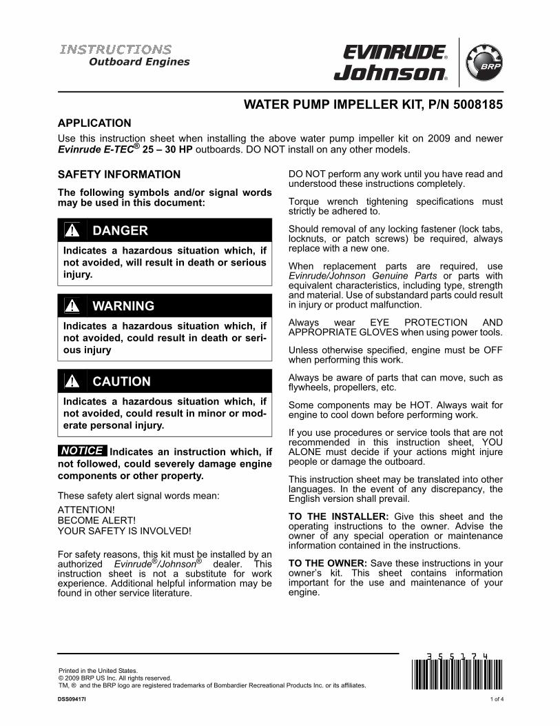
Apply a light coat of Gasket Sealing Compoundto the o-ring and place in the groove in thepressure valve plate.
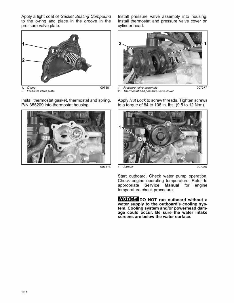
Install thermostat gasket, thermostat and spring,P/N 355209 into thermostat housing.
Install pressure valve assembly into housing.Install thermostat and pressure valve cover oncylinder head.
Apply Nut Lock to screw threads. Tighten screwsto a torque of 84 to 106 in. lbs. (9.5 to 12 N·m).
Start outboard. Check water pump operation.Check engine operating temperature. Refer toappropriate Service Manual for enginetemperature check procedure.
DO NOT run outboard without awater supply to the outboard’s cooling sys-tem. Cooling system and/or powerhead dam-age could occur. Be sure the water intakescreens are below the water surface.
1. O-ring2. Pressure valve plate
007381
007378
1
2
1. Pressure valve assembly2. Thermostat and pressure valve cover
007377
1. Screws 007376
12
1
NOTICE

Outboard Engines
KIT DE TURBINE DE POMPE À EAU, N° RÉF. 5008185
APPLICATIONUtiliser cette fiche d'instructions lors de l'installation du kit de turbine de pompe à eau susmentionnésur les moteurs Evinrude E-TEC® 25–30 cv et postérieurs. Ne l’installer sur AUCUN autre modèle.
INFORMATIONS SUR LA SÉCURITÉ
Il se peut que les symboles et/ou mots indica-tifs suivants apparaissent dans le présentdocument :
Indique une instruction qui, si ellen'est pas suivie, risque de gravementendommager les composants du moteur oude causer d'autres dégâts matériels.
Ces mots destinés à attirer l’attention sur la sécuri-té signifient :
ATTENTION !ÊTRE VIGILANT !LA SÉCURITÉ EST EN JEU !
Pour des raisons de sécurité, ce kit doit être installépar un concessionnaire agrééEvinrude®/Johnson®. Cette fiche d'instructions neremplace pas l’expérience professionnelle. Les
autres documents relatifs à l'entretien comportentdes compléments d'information utiles.
N'effectuer AUCUNE opération avant d'avoir lu etveillé à bien comprendre ces instructions.
Les spécifications de serrage par clédynamométrique doivent être strictementrespectées.
Si le retrait d'une fixation bloquante quelconque(languettes de verrouillage, écrous de blocage ouvis de réparation) s'avère nécessaire, toujours laremplacer par une neuve.
Lorsque des pièces de rechange sont nécessaires,utiliser des pièces d’origine Evinrude/Johnson oudes pièces ayant des caractéristiqueséquivalentes, y compris le type, la résistance et lematériau. L’utilisation de pièces de qualitéinférieure peut entraîner des blessures ou unmauvais fonctionnement du produit.
Toujours porter des LUNETTES DEPROTECTION ET DES GANTS APPROPRIÉSpour utiliser des outils électriques.
Sauf indication contraire, le moteur doit êtreARRÊTÉ pour effectuer une telle opération.
Toujours faire attention aux pièces mobiles tellesque volants-moteurs, hélices, etc.
Certains composants peuvent être CHAUDS.Toujours laisser le moteur refroidir avant detravailler dessus.
S’il utilise des procédures ou des outils d’entretienqui ne sont pas recommandés dans cette fiched'instructions, SEUL LE TECHNICIEN doit décidersi ses actions risquent de blesser des personnesou d’endommager le moteur hors-bord.
Il se peut que la présente fiche d'instructions soittraduite dans d'autres langues. En cas de disparité,c’est la version anglaise qui prévaudra.
DANGER
Indique une situation dangereuse qui, sielle n’est pas évitée, entraînera la mort oudes blessures graves.
AVERTISSEMENT
Indique une situation dangereuse qui, sielle n’est pas évitée, risque d’entraîner lamort ou des blessures graves
ATTENTION
Indique une situation dangereuse qui, sielle n’est pas évitée, risque d’entraînerdes blessures légères ou moyennementgraves.
AVIS
Imprimé aux États-Unis.© 2009 BRP US Inc. Tous droits réservés.TM, ® et le logo BRP sont des marques déposées de Bombardier Recreational Products Inc. ou de ses filiales.
DSS09417I 1 / 4
À L’INTENTION DE L’INSTALLATEUR :Remettre cette fiche ainsi que les instructionsd'utilisation au propriétaire. Attirer l’attention dupropriétaire sur toute information particulièred’utilisation et d’entretien contenue dans cesinstructions.
À L’INTENTION DU PROPRIÉTAIRE : Conserverces instructions dans le kit du propriétaire. Cettefiche donne des informations importantes pourl’utilisation et l’entretien du moteur.
KIT TURBINE POMPE A EAU
APPLICATION
Modèles 2011 et plus récents
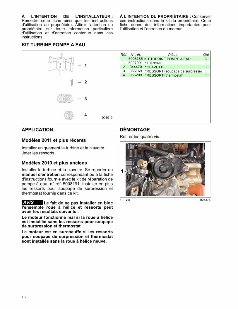
Installer uniquement la turbine et la clavette. Jeter les ressorts.
Modèles 2010 et plus anciens
Installer la turbine et la clavette. Se reporter aumanuel d'entretien correspondant ou à la fiched'instructions fournie avec le kit de réparation depompe à eau, n° réf. 5008191. Installer en plusles ressorts pour soupape de surpression etthermostat fournis dans ce kit.
Le fait de ne pas installer en blocl'ensemble roue à hélice et ressorts peutavoir les résultats suivants :Le moteur fonctionne mal si la roue à héliceest installée sans les ressorts pour soupapede surpression et thermostat.Le moteur est en surchauffe si les ressortspour soupape de surpression et thermostatsont installés sans la roue à hélice neuve.
DÉMONTAGE
Retirer les quatre vis.
Réf. N° réf. Pièce Qté5008185 KIT TURBINE POMPE A EAU 1
1 5007991 *TURBINE 12 344470 *CLAVETTE 13 355169 *RESSORT (soupape de surpressio 14 355209 *RESSORT (thermostat) 1
008019
1
2
3
4
AVIS1. Vis 007376
1
2 / 4

Retirer le couvercle de thermostat et derégulateur de pression de la culasse. Retirer lerégulateur de pression.
Retirer le ressort, le thermostat et le joint dethermostat.
INSPECTION
Examiner toutes les pièces pour voir si elles sontfêlées, endommagées par la chaleur, ou si ellesprésentent des signes de corrosion. Remplacerles pièces endommagées. Éliminer les débris duboîtier et des pièces.
Retirer la vis du plongeur. Retirer le plongeur et leressort de la plaque porte-régulateur de pression.
MONTAGE
Le montage est l’inverse du démontage. Fairetrès attention lorsqu’on exécute les tâchessuivantes.
Placer le ressort, n° réf. 355169, sur le plongeur.Aligner le plongeur sur la plaque porte-régulateurde pression. Placer la membrane et le support surla plaque. Poser la vis.
IMPORTANT : Tourner la vis autotaraudeusedans le sens inverse des aiguilles d'une montrepour engager le filetage, et dans le sens desaiguilles d'une montre pour serrer. Sinon, le file-tage du plongeur risque d'être endommagé.
1. Couvercle de thermostat et de régulateur de pression
2. Régulateur de pression
007377
1. Ressort 007378
007379
21
1
1. Vis 008024
1. Ressort2. Plongeur3. Plaque porte-régulateur de pression4. Membrane5. Support6. Vis
007380A
1
2 1 3 4 5 6
3 / 4

Bien serrer la vis.
Appliquer une mince couche de composéd'étanchéité de joint sur le joint torique et leplacer dans la gorge de la plaqueporte-régulateur de pression.
Mettre en place le joint de thermostat, lethermostat et le ressort, n° réf. 355209, dans leboîtier de thermostat.
Poser la soupape de surpression dans lelogement. Mettre en place le couvercle dethermostat et de régulateur de pression sur laculasse.
Appliquer du Nut Lock sur le filetage de la vis.Serrer les vis à un couple de 84 à 106 lb-po (9,5à 12 N m).
Faire démarrer le moteur hors-bord. Vérifier lefonctionnement de la pompe à eau. Vérifier latempérature de fonctionnement du moteur.Consulter le manuel d'entretien correspondantpour la procédure de contrôle de la températuredu moteur.
NE PAS faire tourner le moteurhors-bord sans que son circuit de refroidis-sement soit alimenté en eau. Ce circuit et/oule bloc-moteur risqueraient d’être endomma-gés. S'assurer que les crépines de prisesd’eau sont immergées.
1. Vis 008024
1. Joint torique2. Plaque porte-régulateur de pression
007381
007378
1
1
2
1. Régulateur de pression2. Couvercle de thermostat et de régulateur de
pression
007377
1. Vis 007376
12
1
AVIS
4 / 4