water everywhere - proboat.com · 18 professional boatbuilder foam core retained acceptable...
TRANSCRIPT

18 Professional BoatBuilder
foam core retained acceptable struc-tural properties, while the uniformly unfilled kerfs provided good flow paths for injected resin. As Scalvini cautions, however, not every boat in need of core repair will have that combination of construction details and materials. Scalvini-as-surveyor performed extensive diagnostic testing, but I’m impressed by his actual repair: infus-ing resin into small areas, while mon-itoring the flow and exotherm with thermal-imaging equipment. That pairing removed the guesswork and blind faith common to most injection repairs. His crew could literally see where vacuum-assisted injection did
I’ve been a skeptic of resin-injection repairs since I disassembled one of my own injection projects 30 years ago. What I found then did not impress me, and neither have most injection repairs I’ve seen since—if for no other reason than their effectiveness could not be determined without extensive destructive testing. The repair Roby Scalvini describes in the following article made me rethink my position. Special characteristics of the sloop Cinderella II made it a good candi-date for infusion repair: the inner skin laminates were hydrolytically stable; and though compromised, the PVC
Above—On the bottom of the 104' (31.7m) sloop Cinderella II, a working panel is dressed with vacuum lines and ready for resin infusion. The foam-core kerfs had suffered significant water intrusion that made the yacht all but unsalable before the repair.
Water EverywhereWe review the diagnosis and repair—an inventive infusion repair, at that—of a pedigreed custom composite sailing yacht that had been rendered virtually worthless by water, and/or high moisture levels, throughout the hull bottom.
Text and photographs by Roby Scalvini
Introduction by Bruce Pfund

august/sePtemBer 2010 19
The owner refused to accept that his boat might be a total loss. So,
in autumn 2008, on the advice of his broker in the United Kingdom—a broker for whom we’d done some past projects—Cinderella II ’s owner engaged our firm, Marine Survey Bureau in Palma de Mallorca, to carry out an in-depth quantitative assessment of damage and to devise a suitable repair. The designer’s office provided us with detailed construction drawings and laminate schedules. Built over a male mold, the hull is of hand-laid sandwich construction: epoxy resin, E-glass, and hybrid E-glass/Kevlar laminates. The core is Divinycell H-100 cross-linked PVC foam (scored type), 1.5" (38.1mm) thick. The exte-rior above the waterline was thor-oughly faired and finished with a professionally applied linear polyure-thane coating.
Assessment and Findings Our first objective was to measure the extent of water intrusion and to identify areas saturated with water, as distinct from areas with merely ele-vated moisture levels and those that were dry. Throughout the diagnostic phase we relied on a combination of non-destructive techniques—electronic moisture meters and infrared ther-mography—along with destructive sampling of material for testing in the laboratory. Here’s what we found:
• The hull bottom was affected by two separate conditions with no obvious direct causal connection to each other, namely: widespread high-moisture levels in the outer skin
not succeed, and they then pressure- injected the unfilled kerfs. Cinderella II’s high-quality infusion repair greatly increased the yacht’s market value, which was no doubt bolstered by careful documentation of the work. The latter feature, I’ve found, is an often neglected compo-nent of big repair projects.
—Bruce Pfund, Technical Editor
The well-known Tripp-designed oceangoing luxury charter yacht
Cinderella II was expected to sell quickly. But when the first offer came along subject to survey, and the boat was hauled out at STP Boatyard in Palma de Mallorca, Spain, for an inspection, the buyer’s surveyor detected very high levels of moisture in the bottom laminate. Because both parties were keen to complete the transaction, they agreed to investigate the cause through limited destructive testing of the composite structure. Fairing compound was shot-blasted off the bottom to minimize interfer-ence with moisture readings, which indicated that the bottom was wet throughout. A 1" (25mm) core sam-ple was taken, followed by more exploratory holes drilled in the outer skin. Those yielded less uniform but equally unsettling results. In some areas, the core appeared thoroughly dry, while in others almost 5 gal (18.9 l) of water were drained from the hull. The prospective buyer walked away, hastily. Cinderella II ’ s hul l problem became a matter of public knowledge in brokerage circles worldwide, just when the current recession seemed at its worst. Since the seller was about to take delivery of a newly built larger yacht, Cinderella II ’s asking price was reduced fourfold, from $4 million to less than $1 million. A few bargain-hunters showed some interest, but despite the boat’s above-average gen-eral condition, water in the core made them depart, fearing the hull was structurally deficient.
Blackened empty kerfs in this cross section of PVC core indicate that a considerable volume of water sat in the core. The white putty only partially filling the kerfs did not stop water from migrating throughout the core once it had entered a breach in the outer skin.
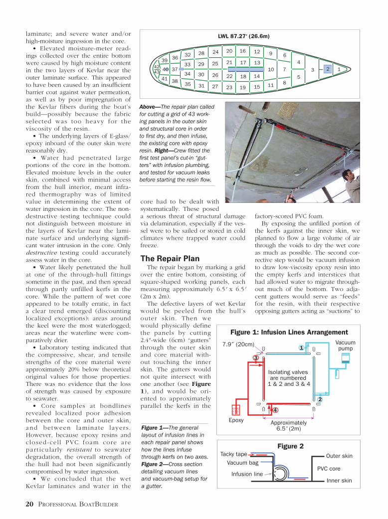
Type: Auxiliary sloop Designer: Bill Tripp Year: 1992 LOA: 104' (31.70m) LWL: 87.27' (26.60m) Beam: 23.62' (7.20m) Draft: 11.48' (3.50m) Displ.: 216,052 lbs (98 tons)
Cinderella II Particulars
20 Professional BoatBuilder
factory-scored PVC foam. By exposing the unfilled portion of the kerfs against the inner skin, we planned to flow a large volume of air through the voids to dry the wet core as much as possible. The second cor-rective step would be vacuum infusion to draw low-viscosity epoxy resin into the empty kerfs and interstices that had allowed water to migrate through-out much of the bottom. Two adja-cent gutters would serve as “feeds” for the resin, with their respective opposing gutters acting as “suctions” to
core had to be dealt with systematically. These posed a serious threat of structural damage via delamination, especially if the ves-sel were to be sailed or stored in cold climates where trapped water could freeze.
The Repair Plan The repair began by marking a grid over the entire bottom, consisting of square-shaped working panels, each measuring approximately 6.5' x 6.5' (2m x 2m). The defective layers of wet Kevlar would be peeled from the hull’s outer skin. Then we would physically define the panels by cutting 2.4" -wide (6cm) “gutters” through the outer skin and core material with-out touching the inner skin. The gutters would not quite intersect with one another (see Figure 1), and would be ori-ented to approximately parallel the kerfs in the
laminate; and severe water and/or high-moisture ingression in the core. • Elevated moisture-meter read-ings collected over the entire bottom were caused by high moisture content in the two layers of Kevlar near the outer laminate surface. This appeared to have been caused by an insufficient barrier coat against water permeation, as well as by poor impregnation of the Kevlar fibers during the boat’s build—possibly because the fabric selected was too heavy for the viscosity of the resin. • The underlying layers of E-glass/epoxy inboard of the outer skin were reasonably dry. • Water had penetrated large portions of the core in the bottom. Elevated moisture levels in the outer skin, combined with minimal access from the hull interior, meant infra-red thermography was of limited value in determining the extent of water ingression in the core. The non-destructive testing technique could not distinguish between moisture in the layers of Kevlar near the lami-nate surface and underlying signifi-cant water intrusion in the core. Only destructive testing could accurately assess water in the core. • Water likely penetrated the hull at one of the through-hull fittings sometime in the past, and then spread through partly unfilled kerfs in the core. While the pattern of wet core appeared to be totally erratic, in fact a clear trend emerged (discounting localized exceptions): areas around the keel were the most waterlogged; areas near the waterline were com-paratively drier. • Laboratory testing indicated that the compressive, shear, and tensile strengths of the core material were approximately 20% below theoretical original values for those properties. There was no evidence that the loss of strength was caused by exposure to seawater. • Core samples at bondlines revealed localized poor adhesion between the core and outer skin, and between laminate layers . However, because epoxy resins and closed-cel l PVC foam core are par t icularly resistant to seawater degradation, the overall strength of the hull had not been significantly compromised by water ingression. • We concluded that the wet Kevlar laminates and water in the
LWL 87.27' (26.6m)
40
323639
41 38
3733
34
35
28
29
30
31
24
25
26
27
20
21
22
23
16
17
18
19 15
14
13
12 9
10
11
6
7
85
4
3 124243
Tacky tapeFigure 2
Vacuum bag
Infusion line
Outer skin
Inner skin
PVC core
1
3
4
2
Isolating valves are numbered
1 & 2 and 3 & 4
Figure 1: Infusion Lines Arrangement
Approximately6.5' (2m)
Epoxy
Vacuumpump
7.9˝ (20cm)
Above—The repair plan called for cutting a grid of 43 work-ing panels in the outer skin and structural core in order to first dry, and then infuse, the existing core with epoxy resin. Right—Crew fitted the first test panel’s cut-in “gut-ters” with infusion plumbing, and tested for vacuum leaks before starting the resin flow.
Figure 1—The general layout of infusion lines in each repair panel shows how the lines infuse through kerfs on two axes. Figure 2—Cross section detailing vacuum lines and vacuum-bag setup for a gutter.

august/sePtemBer 2010 21
Then we removed all through-hull fittings below the waterline. The damp outer layers of Kevlar were poorly adhered to underlying E-glass plies. After scoring the outer skin with a circular saw in our working pat-tern of square panels, we peeled the Kevlar from the underlying laminates over the entire bottom, one square at a time. The crew was careful to maintain correct scarf ratios—in excess of 1:25 at the waterline and around the five hull supports—to receive new laminate. Minor gouges in the laminate, from scoring and removing the Kevlar layers, were individu-ally filled and faired with WEST SySTEM epoxy thickened with 50% microfiber and 50% colloidal silica.
draw vacuum during the infusion (see Figures 1 and 2). Upon successful infusion of epoxy resin into the core, the gutters would be closed by inserting new core material—to act as an additional barrier against any future migration of water along the kerfs. Once all the gutters were closed, the entire bottom would be re-laminated with layers of Kevlar and E-glass. We specified that all products in the repair have properties consistent with and/or exceeding those of the original construction. With the projected repair roughed out, we hired Sebastian Sitjar and his crew, who are well known locally for composites repairs, to join our team. We first made a test panel to experi-ment with, and a few days later fine-tuned the procedure we would repeat many times on the hull bottom. We drew up a detailed repair schedule and budget, and presented the repair agreement to the owner for his approval. Then, to work.
Restoring the Bottom First, we built a full tent over the boat to protect the working area from the elements. The structure was big enough to accommodate ample scaf-folding for crews to reach all of the hull repair area. Next, we brought in four diesel-fired 80-kW exterior air-heaters, each with adequate ducting inside the tent to adjust temperature and humidity—extremely important for controlling resin viscosity during infusion and post-cure.
Cinderella II was hauled out and fully tented at STP Boatyard, in Palma de Mallorca, Spain. Inset—One of four 80-kW diesel-fired heaters employed in the work area during the temperature-sensitive repair.
Above—The crew removed layers of wet Kevlar in the outer skin with wedges: crude, but effective. Right—Near the waterline, ample scarf ratios ground into the existing outer skin will receive new laminates to complete the repair. Below right—Detail of core sealing at the panels’ corners.
The bow’s triangular panel (#1) is dried by pumping air through the network of empty core kerfs. Red arrows indicate compressed-air feed lines; the green arrow, an air suction line.

22 Professional BoatBuilder
regenerative-type vacuum blowers were essential to drying the core. (On our test panel, we’d discovered that the trusty Shop-Vac was simply not up to the job.) We alternated the direction of air-flow between the two axes of a panel until a Sovereign moisture meter, placed on the outer skin, measured sat-isfactory moisture levels. We deemed Level 10 on the instrument’s “A” scale to be satisfactory. With the setup described here, three or four panels could be drying at the same time. Once a panel was sufficiently dry, we placed resin-supply and suction lines in the gutters under a vacuum bag (Figure 2), and infused the panel with extremely low viscosity (70–90 centipoise) Prime Rez 1200 epoxy
With the damp Kevlar out of the way, we deepened the grid of work panels to address the wet core by j igsawing 2.4"-wide gutters into the remaining outer skin laminate. The ends of each gutter were rounded to a radius of about 1.2" (3cm) and spaced 7.9" (20cm) from the end of the next gutter. The uppermost fore-and-aft gutters were located 11.8" (30cm) below the upper extent of antifoulant at the waterline. The crew kept to the prescribed sequence when “attacking” the panels, which were staggered throughout the bottom of the boat to avoid undue or uneven weakening of the hull. Once the grid of gutters had been cut through the outer laminate, we removed underlying core material with an oscillating cutting tool. The deep-ened gutters were thoroughly cleaned with a small belt sander to expose, but not compromise, the inner skin.
Where kerf cross-sections intersected the newly cut gutters, they were opened up one by one with a custom tool to ensure good air/resin flow. We sealed the four corners of each panel by horizontally drilling out sections of core beneath the areas of outer skin that remained between the ends of the gutters, and then filled the holes with cylindrically shaped PVC core and high-density epoxy filler. To effec-tively isolate the open kerfs of any one panel from those of adjacent pan-els was important for the core drying, and the resin re-infusion to come. We dried the wet core by forcing compressed dry air at a maximum pressure of 1 bar into two adjacent gutters while drawing air from their respective opposites in the working panel. Sealing flanges were temporar-ily laminated over the feed gutters to receive the compressed-air nozzles. On the suction gutters the high-volume
Non-dimensionalizes vessel speed and length by accounting for fluid properties: density (ρ) and dynamic viscosity (µ)
Type of vacuum pump(characteristics)
Regenerative-type vacuum blowers(good volume, moderate pressure)
150 60
Airflow(CFM)
Vacuum level(inches of H
20)
Re=ρ x V x L
µ
Reynolds Number
Regenerative-Type Vacuum Blowers vs. Other Vacuum Types
Slide 2
Rotary-vane vacuum pump(very high pressure with very low volume)
30 350
Radial blower(very high volume with very low pressure)
700 25
Industrial Shop-Vac
Note:• The above values represent pumps with comparable power output of 2 hp.• Rotary-vane vacuum pumps are typically employed for vacuum-bagging and general resin infusion in the marine industry.• Most regenerative-type blowers are available as both vacuum or pressure pumps and have the advantage of being available in 3-phase, which is more efficient and heavy duty than a conventional Shop Vac.
Vacuum for these pumps is expressed either in inches of H2O (water), or inches of
Hg (mercury): 1" hg = 13.59" H2O.
Vacuum may also be expressed in torr: 1" Hg = 25.4 torr.
120 50
Far left—A thermograph of panel #26 during infusion shows “hot” resin (red) in the feed line and along the kerfs. Left—The side of a gutter after infusion: the green arrow indicates the portion of kerf originally filled with putty; and the red arrow, the portion successfully filled by the infused repair.
Non-dimensionalizes vessel speed and length by accounting for fluid properties: density (ρ) and dynamic viscosity (µ)
Re=ρ x V x L
µ
Reynolds Number
Slide 2
Type of vacuum pump(characteristics)
Regenerative type vacuum blowers(good volume moderate pressure)
150 60
Air flow(CFM)
Vacuum level(Inches of H
20)
Regenerative-type vacuum blowers vs. other vacuum types
Rotary vane vacuum pump(very high-pressure with very low volume)
30 350
Radial blower(very high volume with very low pressure)
700 25
Industrial Shop-Vac
Note:• The above values represent pumps with comparable power output of 2 H.P.• Rotary vane vacuum pumps are typically employed for vacuum bagging and general resin infusion in the marine industry.• Most regenerative type blowers are available as both vacuum or pressure pumps and have the advantage to be available in 3-phase wich is more efficient and heavy duty than conventional ShopVac.
(For these pumps vacuum is expressed either in ‘Inches of H20’ or ‘Inches of Hg’–
1 ‘inch of Hg’ equal to 13.59 ‘Inches of H20’. Vacuum may also be expressed in ‘Torr’
–1 ‘inch of Hg’ equal to 25.4 ‘Torr’.
120 50
*Prime Rez 1200 70 c.p.
*Sicomin SR8100 110 c.p.
*SP Prime 20 ULV 140 c.p.
*Resoltech 1800 180 c.p.
*PRO-SET 117 LV 300 c.p.
+Ampreg 21 430 c.p.
+PRO-SET 125/229 450 c.p.
+WEST SYSTEM 105/209 650 c.p.
Low-Viscosity Infusion and General-Purpose Epoxies
Epoxy Viscosity
Viscosity expressed in centipoise at 25°C/77°F. 1,000 centipoise = 1 pascal.
* Epoxy resins specifically designed for infusion applications+ General-purpose low-viscosity resins.All resins above are believed to be 100% solids.
Note: Prime Rez 1200 should not be considered an alternative to more widely tested epoxy resins specifically manufactured for the marine industry. However, in repairs where extremely low viscosity is an essential prerequisite, it has its place.

24 Professional BoatBuilder
When all panels were completed, we re-laminated the entire bottom (apart from the areas beneath the five main vessel supports), employing the following schedule:
• 1 layer biaxial 45°/45°, 450-g/m2 (1.50-oz/sq-ft) knitted E-glass• 2 layers biaxial C77K 0°/90°, 600-g/m2 (2-oz/sq-ft) hybrid E-glass/Kevlar• 1 layer biaxial 45°/45°, 881-g/m2
(3-oz/sq-ft) knitted E-glass• 2 layers biaxial C77K 0°/90°, 600-g/m2 (2-oz/sq-ft) hybrid E-glass/Kevlar • 1 layer biaxial 45°/45°, 450-g/m2 (1.50-oz/sq-ft) knitted E-glass
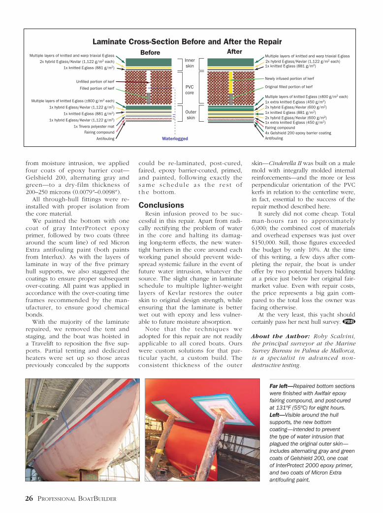
Note that the original laminate schedule featured two layers of hybrid E-glass/Kevlar 1,122 g/m2 (3.7 oz/sq ft), which were replaced by four layers of custom-made 600-g/m2 (2-oz/sq-ft) fabric to ensure better impregnation. All laminating epoxy resin for the repair was PRO-SET type 125, with 226- and 229-type hardeners. Once the lamination was com-pleted, we faired the bottom—again, apart from the areas in way of the hull supports—with Awlfair (an Awlgrip product) sandable epoxy fair-ing compound, and post-cured it to 131°F for more than eight hours. Next, to further seal the outer skin
ultrasound leak detector. Most panels were successfully infused purely by vacuum as indicated; however, a few required applying posit ive pressure—by literally injecting resin into the empty kerfs at the gutters. The net amount of resin infused into the bottom area was about 60 gal (230 l), which corresponded to our calculation of the approximate total volume of unfilled kerfs. After all the panels around the gut-ters had been infused, we cleaned the gutters again and filled them with
pre-scored 100-kg/m3
(6.24-lb/cu-ft) cross-linked PVC foam, 11⁄2" (38.1mm) thick, set in PRO-SET epoxy res in th ickened wi th 50% microfiber and 50% silica as a core bond. Then, outer-skin laminates around the gutter perim-eters were chamfered with an angle grinder to a 1:25 scarf ratio, and re- laminated—repeating the original laminate schedule up to the last E-glass layer before the first layer of Kevlar. Completed panels were individually post-cured to 131°F (55°C) for more than eight hours.
resin. Our preliminary tests indicated that low viscosity and high vacuum levels were essential to the success of this particular repair. Like the drying process, resin was infused first along one axis of the panel’s kerf cuts; and when epoxy came through to the suc-tion decanter, more resin was infused along the kerfs perpendicular to that axis. When resin reached the suction decanter from that axis, the panel was considered saturated. Throughout the infusion, we moni-tored vacuum integrity with an
Repair crews employed heat-load laser shearography of the hull (bottom inset) to validate the lamination repair scarfs. The inset shearogram shows good structural transition between the original laminate and the replacement covering the gutter, indicated by the arrow between panels 31 and 27.
Lamination in way of one of the boat’s supports illustrates the ample scarf ratio between layers of reinforcing fibers in the outer-skin replacement. Its laminate schedule was slightly altered from the original. G signifies E-glass; K, Kevlar.
26 Professional BoatBuilder
skin—Cinderella II was built on a male mold with integrally molded internal reinforcements—and the more or less perpendicular orientation of the PVC kerfs in relation to the centerline were, in fact, essential to the success of the repair method described here. It surely did not come cheap. Total man-hours ran to approximately 6,000; the combined cost of materials and overhead expenses was just over $150,000. Still, those figures exceeded the budget by only 10%. At the time of this writing, a few days after com-pleting the repair, the boat is under offer by two potential buyers bidding at a price just below her original fair-market value. Even with repair costs, the price represents a big gain com-pared to the total loss the owner was facing otherwise. At the very least, this yacht should certainly pass her next hull survey.
About the Author: Roby Scalvini, the principal surveyor at the Marine Survey Bureau in Palma de Mallorca, is a specialist in advanced non-destructive testing.
could be re-laminated, post-cured, faired, epoxy barrier-coated, primed, and painted, following exactly the s ame s chedu le a s t he r e s t o f t h e bottom.
Conclusions Resin infusion proved to be suc-cessful in this repair. Apart from radi-cally rectifying the problem of water in the core and halting its damag-ing long-term effects, the new water-tight barriers in the core around each working panel should prevent wide-spread systemic failure in the event of future water intrusion, whatever the source. The slight change in laminate schedule to multiple lighter-weight layers of Kevlar restores the outer skin to original design strength, while ensuring that the laminate is better wet out with epoxy and less vulner-able to future moisture absorption. Note that the techniques we adopted for this repair are not readily applicable to all cored boats. Ours were custom solutions for that par-ticular yacht, a custom build. The consistent thickness of the outer
from moisture intrusion, we applied four coats of epoxy barrier coat—Gelshield 200, alternating gray and green—to a dry-film thickness of 200–250 microns (0.0079"–0.0098" ). All through-hull fittings were re-installed with proper isolation from the core material. We painted the bottom with one coat of gray InterProtect epoxy primer, followed by two coats (three around the scum line) of red Micron Extra antifouling paint (both paints from Interlux). As with the layers of laminate in way of the five primary hull supports, we also staggered the coatings to ensure proper subsequent over-coating. All paint was applied in accordance with the over-coating time frames recommended by the man-ufacturer, to ensure good chemical bonds. With the majority of the laminate repaired, we removed the tent and staging, and the boat was hoisted in a Travelift to reposition the five sup-ports. Partial tenting and dedicated heaters were set up so those areas previously concealed by the supports
Laminate Cross-Section Before and After the RepairBefore After
Multiple layers of knitted and warp triaxial E-glassInnerskin
Outerskin
PVCcore
Waterlogged
2x hybrid E-glass/Kevlar (1,122 g/m2 each)
1x hybrid E-glass/Kevlar (1,122 g/m2)
1x hybrid E-glass/Kevlar (1,122 g/m2)
1x knitted E-glass (881 g/m2)
1x Trivera polyester matFairing compound
Antifouling
1x knitted E-glass (881 g/m2)
Un�lled portion of kerf
Filled portion of kerf
Multiple layers of knitted E-glass (±800 g/m2 each)
Multiple layers of knitted and warp triaxial E-glass2x hybrid E-glass/Kevlar (1,122 g/m2 each)
2x hybrid E-glass/Kevlar (600 g/m2)
2x hybrid E-glass/Kevlar (600 g/m2)
1x extra knitted E-glass (450 g/m2)
1x extra knitted E-glass (450 g/m2)
1x knitted E-glass (881 g/m2)
Fairing compound
Antifouling4x Gelshield 200 epoxy barrier coating
1x knitted E-glass (881 g/m2)
Newly infused portion of kerf
Original �lled portion of kerf
Multiple layers of knitted E-glass (±800 g/m2 each)
Far left—Repaired bottom sections were finished with Awlfair epoxy fairing compound, and post-cured at 131ºF (55ºC) for eight hours. Left—Visible around the hull supports, the new bottom coating—intended to prevent the type of water intrusion that plagued the original outer skin—includes alternating gray and green coats of Gelshield 200, one coat of InterProtect 2000 epoxy primer, and two coats of Micron Extra antifouling paint.