water and wastewater system standard specifications
TRANSCRIPT

Water and Wastewater System Standard Specifications
Adopted October 2007
Revised September 2008
July 2009 August 2011
September 2014 January 2019
July 2020


Water and Wastewater System Standard Specifications
Widefield Water and Sanitation District
8495 Fontaine Blvd
Colorado Springs, CO 80925
Phone (719) 390-7111
Adopted October 2, 2007
Revisions:
September 2008
July 2009
August 2011
September 2014
January 2019
July 2020


Revised July 2020 Page ii
TABLE OF CONTENTS
Section 1.0 General Standards Page
1.1 Purpose 1
1.2 Revisions, Amendments, or Additions 1
1.3 Effect of Specifications 1
1.4 Authority 1
1.5 Interpretation of Specifications 1
1.6 Definitions 1
1.7 Abbreviations 2
1.8 Reference Specifications 3
1.9 Requirements to Extend, Construct, or Modify System 3
1.9.1 Request for Development Information
1.9.2 Preliminary Review for Large Projects
1.9.3 Request for Recovery Contract
1.9.4 Plan Format, Submission, Review and As-builts
1.9.5 Pre-construction Conference
1.10 Construction Matters 7
1.10.1 Conflicts Between Plans and Specifications
1.10.2 Construction Procedure
1.10.3 Surveying
1.10.4 Placing Survey lines
1.10.5 Inspection
1.10.6 Abandonments, Material Recovery, and Reuse of Installed Material
1.10.7 Warranty and Acceptance
Section 2.0 Water System Line Design Standards
2.1 General 11
2.1.1 Deviation from Standard
2.1.2 Easements
2.1.3 Colorado Department of Health Regulations
2.2 Hydraulics 11
2.2.1 Sizing of Water Mains
2.2.2 Sizing of Services
2.3 Water Mains 12
2.3.1 Locations
2.3.2 Material
2.3.3 Corrosion Protection
2.3.4 Profile
2.3.5 Looping
2.4 Valving 12
2.4.1 Location
2.5 Appurtenances 13
2.5.1 Blow-off Valves
2.5.2 Air Release Valves
2.5.3 Pressure Reducing and Regulating Valves
2.5.4 Fire Hydrants
2.6 Separation from Pollution Sources 13
2.7 Casing 13
2.8 Fire Lines 13

Revised July 2020 Page iii
2.9 Water Main Crossings 14
2.9.1 Asbestos Cement Water Mains
2.9.2 Irrigation Ditch Crossings
2.9.3 Final Inspection
Section 3.0 Water System Installation Standards
3.1 General Construction 15
3.1.1 Start of Construction
3.1.2 Protection of Existing Underground Facilities
3.1.3 Detours – Traffic Control
3.2 Excavation 15
3.2.1 Safety
3.2.2 Construction Stakes
3.2.3 Trench Width
3.2.4 Over Excavation
3.2.5 Blasting
3.2.6 Sheeting and Bracing
3.3 Pipe Bedding and Laying 17
3.3.1 Imported Bedding Material
3.3.2 Laying of Pipe
3.3.3 Length of Pipe
3.3.4 Fittings
3.3.5 Service Connections
3.4 Backfill and Compaction 22
3.5 Valve Installation 23
3.5.1 Valves
3.5.2 Valve Boxes
3.6 Fire Hydrant Installation 24
3.6.1 Installation
3.6.2 Anchorage
3.6.3 Drainage
3.6.4 Hydrant Protection in Corrosive Soils
3.7 Blow-off Installation 25
3.8 Air Release Valve Installation 25
3.9 Pressure Reducing Valve Installation 25
3.10 Disinfection 25
3.11 Hydrostatic Testing 26
3.11.1 General
3.11.2 Procedure
3.11.3 Allowable Leakage
3.12 Water Meter Installation 28
3.12.1 General
3.12.2 Inside Water Meter Installation
3.12.3 Water Meter Pit Installation (Other than Residential)
3.12.4 Combined Domestic and Fire Line Water Meters
3.13 Service Lines 30
3.13.1 General
3.13.2 Service Lines
Section 4.0 Water System Material Standards
4.1 Material Specification General 33

Revised July 2020 Page iv
4.2 Pipe 33
4.2.1 Polyvinyl Chloride (PVC) Pipe
4.2.2 Ductile Iron Pipe
4.2.3 Steel Pipe Fabrication
4.3 Cathodic Protection 34
4.4 Valves 34
4.4.1 Twelve-Inch (12”) Diameter and Smaller
4.4.2 Fourteen-Inch (14”) Diameter and Larger
4.5 Fire Hydrants 35
4.5.1 General
4.5.2 Acceptable Manufacturers
4.5.3 Size of Hydrant
4.5.4 Type of Hydrant
4.5.5 Inlet Connection
4.5.6 Main Valve Assembly
4.5.7 Operating Shaft Nut
4.5.8 Pumper Nozzle and Cap
4.5.9 Hose Nozzles and Cap
4.5.10 Color
4.5.11 Location
4.6 Pressure Reducing Valves 36
4.7 Air Release Valves 37
4.8 Thrust Blocks 37
4.9 Pre-Cast Concrete Vaults and Manholes 37
4.10 Services 37
4.10.1 Service Lines
4.10.2 Corporation Stops and Curb Stops (or valves)
4.10.3 Meters
4.10.4 Backflow Preventers
Section 5.0 Wastewater System Design Standards
5.1 Quality of the Collection System 41
5.2 Sizing of Collection Mains 41
5.3 Layout of the Collection System 41
5.3.1 Sewer Service Lin
5.4 Manholes 41
5.4.1 Manhole Sizes
5.4.2 Changing Pipe Size
5.4.3 Intersection
5.4.4 Manhole Channels
5.4.5 Manhole Ring and Cover
5.4.6 Drop Manholes
5.5 Minimum Sewer Depth 42
5.6 Slopes 42
5.7 Construction Tolerances 43
5.8 High Velocity Protection 43
5.9 Relation to Water Mains 43
5.10 Stub-outs From Manholes 44
5.11 Inverted Siphons 44
5.12 Stream and Drainage Channel Crossings 44
5.13 Crossing Under Railways and Highways 44
5.14 Arial Crossings 44

Revised July 2020 Page v
5.15 Metering Manholes 44
5.16 Pumping Facilities 45
5.17 Force Mains 46
5.18 Swimming Pools 46
Section 6.0 Wastewater System Excavation and Site Standards
6.1 Earthwork Defined 49
6.2 Traffic Control 49
6.3 Caution in Excavation 49
6.4 Excavation to Line and Grade 49
6.5 Trenching and Excavation Operations 49
6.6 Blasting 50
6.7 Dewatering 51
6.8 Pipe Bedding 51
6.9 Backfill and Compaction 53
6.10 Cleanup 53
6.11 Surface Restoration and Maintenance 53
Section 7.0 Wastewater System Pipe Laying Standards
7.1 Handling of Materials 55
7.2 Inspection and Preparation of Pipe and Fittings 55
7.3 Cutting and Fitting of Pipe 55
7.3.1 Pipe Joint Lubrication
7.3.2 Pipe Alignment and Grade
7.3.3 Temporary Bulkheads
7.3.4 Frost
7.3.5 Lowering of Material Into the Trench
7.4 Laying of Pipe 56
7.5 Ductile Iron Pipe 57
7.6 Polyvinyl Chloride Pipe 57
7.7 Manholes 58
7.8 Bridging and Encasement of Pipe 58
7.9 Encasement or Sleeve Pipe 59
7.10 Corrosion Protection Systems 59
7.11 Cleaning 60
7.12 Compaction Tests 60
7.13 Infiltration and Exfiltration Tests 60
7.14 Deflection Test 61
7.15 T.V. Inspection 61
7.16 Vacuum Testing for Concrete Sewer Manholes 62
7.17 Manhole Rim Elevations 63
7.18 Sewer Service Lines and Inspection 64
Section 8.0 Wastewater Services Standards
8.1 Wastewater Taps 65
8.2 Excavations 65
8.3 Abandoning Existing Connections 65
8.4 Individual Service Pumps 65
8.5 Wastewater Service Line Ditches 65
8.6 Inline Wye 65

Revised July 2020 Page vi
8.7 Installation Method 65
8.8 Slope 65
8.9 Alignment 65
8.10 Cleanouts 66
8.11 Connecting Clamps 66
8.12 Repair and Replacement of Existing Service Lines 66
8.12.1 Responsibility
8.12.2 Surface Restoration and Maintenance
Section 9.0 Wastewater System Materials Standards
9.1 Polyvinyl Chloride (PVC)Pipe 69
9.2 Ductile Iron Pipe 69
9.3 HDPE Pipe 70
9.4 Polyethylene Encasement Material 70
9.5 Concrete 71
9.6 Concrete Reinforcement 72
9.7 Precast Reinforced Concrete Manhole Sections 72
9.8 24-Inch Diameter Manhole Ring and Cover 72
Appendices
Appendix A - Request for Deviation Form
Appendix B - District Signature Blocks
Appendix C - WWSD General Notes
Appendix D - Grease Interceptor Standards
Appendix E – Mercury Source Control Policy
Appendix F- Underdrain Policy

Revised July 2020 Page vii
Standard Drawings
Water
No. Title
W-1 Fire Hydrant Locations
W-2 Fire Hydrant Installation
W-3 Fire Hydrant Specifications
W-4 Valve Installation and Location
W-5 Valve Box Installation
W-6 Polyethylene Wrap
W-7 Bonding Joint and Anode Installation
W-8 Insulator Installation
W-9 Tracer Wire Installation Details
W-10 Thrust Block Data
W-11 Thrust Blocks Required for Taps
W-12 Typical Trench Cross Section
W-13 Maximum Pipeline Deflection Data
W-14 Pipe Cutting
W-15 Reverse Anchor Detail
W-16 Water Line Lowering Detail
W-17 Pipe Bridging Detail
W-18 Temporary and Permanent Blow-Off Assemblies for 6" and 8" Mains
W-19 Temporary and Permanent Blow-Off Assemblies for 12" and Larger
W-20 Blow-Off Assembly Dimension Data for 12-inch or Larger
W-21 Pipe Tapping Detail
W-22 Cul-de-Sac Blow Off Detail
W-23 Flange - Lug Detail
W-24 Applications for Mechanical Joint Restraints
W-25 Restrained M.J. Pipe Length Data
W-26 Pressure Relief Station
W-27 8" Size Pressure Regulator Station
W-28 6" Size Pressure Regulator Station
W-29 Standard Concrete Vault for Valve Installations - Precast
W-30 Standard Concrete Vault for Valve Installations - Cast-in-Place Concrete
W-31 Protecting Tie-Rods
W-32 Tapping Detail - 3/4" through 2"
W-33 Typical Installation for Service Line and Stop Box
W-34 Typical Service Line Trench - Common Ditch for Water or Sewer
W-35 Water Meter Loop for 3/4" through 1" Meters
W-36 UNUSED
W-37 Irrigation Service Installation
W-38 Irrigation Meter Vault Installation
W-39 Air/Relief Vacuum Valve Pit
W-40 1-1/2” & 2” Indoor Meter Installation
W-41 Service Line Lowering
Revised July 2020 Page viii
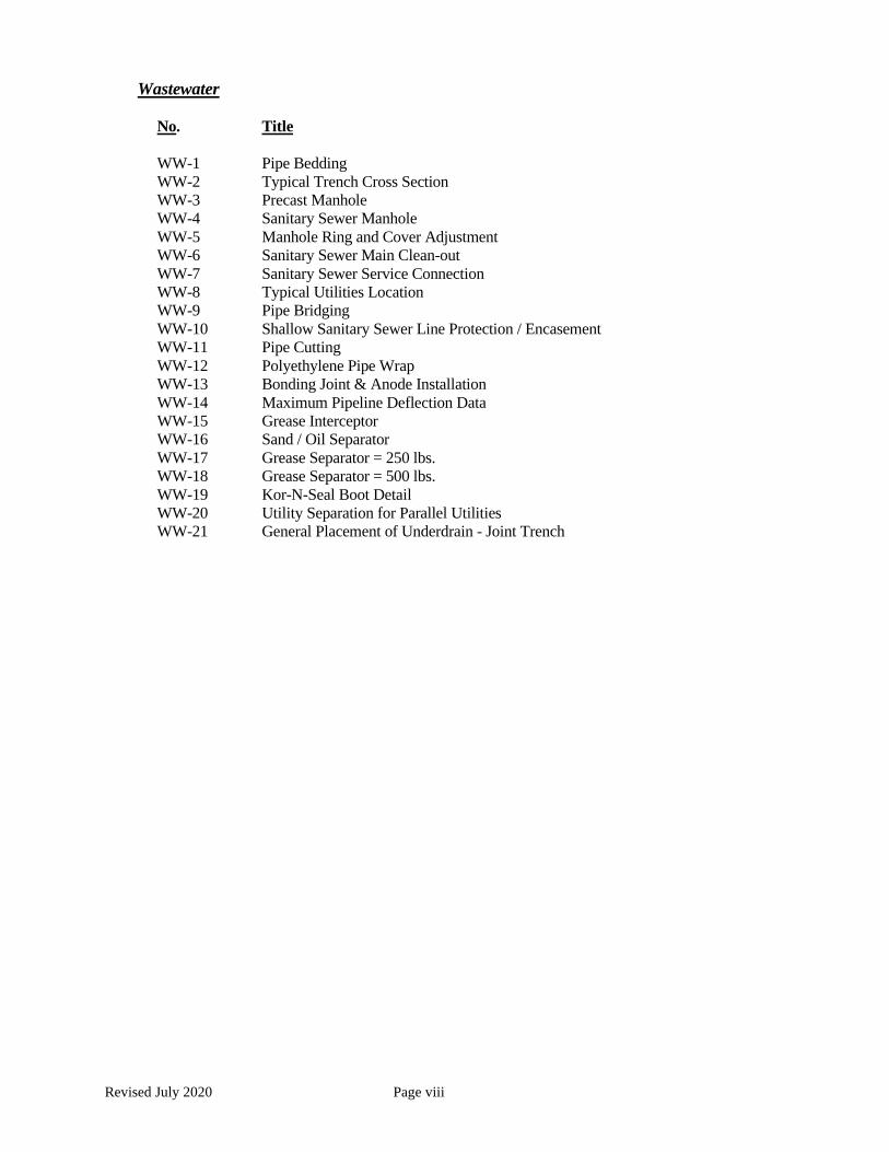
Wastewater
No. Title
WW-1 Pipe Bedding
WW-2 Typical Trench Cross Section
WW-3 Precast Manhole
WW-4 Sanitary Sewer Manhole
WW-5 Manhole Ring and Cover Adjustment
WW-6 Sanitary Sewer Main Clean-out
WW-7 Sanitary Sewer Service Connection
WW-8 Typical Utilities Location
WW-9 Pipe Bridging
WW-10 Shallow Sanitary Sewer Line Protection / Encasement
WW-11 Pipe Cutting
WW-12 Polyethylene Pipe Wrap
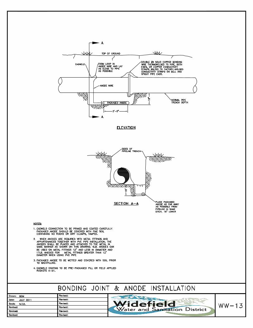
WW-13 Bonding Joint & Anode Installation
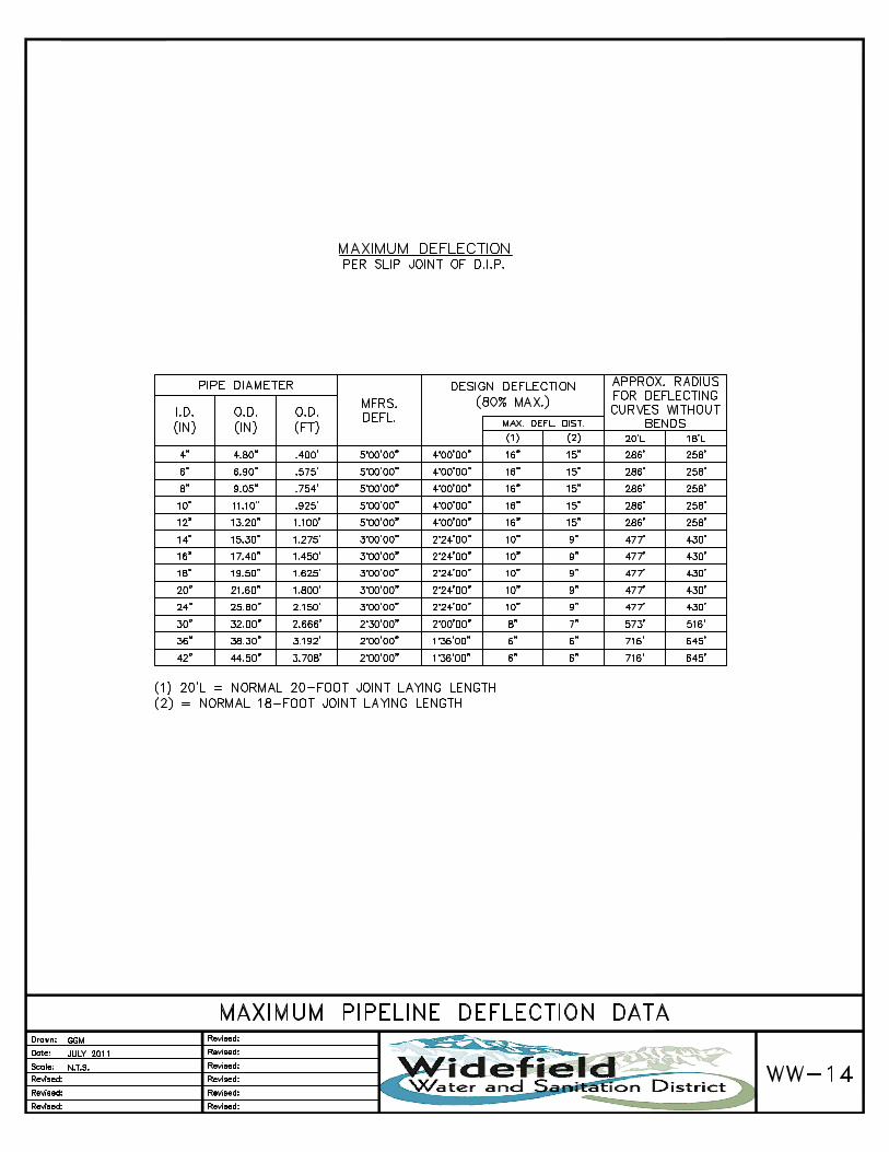
WW-14 Maximum Pipeline Deflection Data
WW-15 Grease Interceptor
WW-16 Sand / Oil Separator
WW-17 Grease Separator = 250 lbs.
WW-18 Grease Separator = 500 lbs.
WW-19 Kor-N-Seal Boot Detail
WW-20 Utility Separation for Parallel Utilities
WW-21 General Placement of Underdrain - Joint Trench

Revised July 2020 Page 1
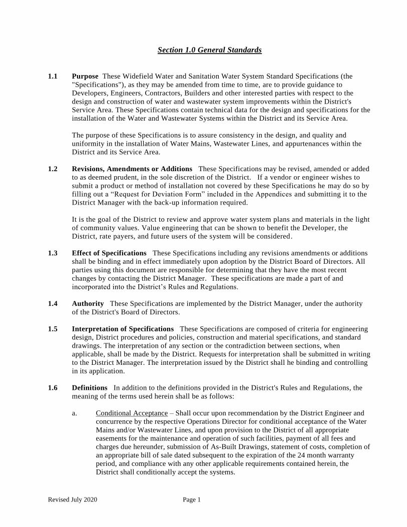
Section 1.0 General Standards
1.1 Purpose These Widefield Water and Sanitation Water System Standard Specifications (the
"Specifications"), as they may be amended from time to time, are to provide guidance to
Developers, Engineers, Contractors, Builders and other interested parties with respect to the
design and construction of water and wastewater system improvements within the District's
Service Area. These Specifications contain technical data for the design and specifications for the
installation of the Water and Wastewater Systems within the District and its Service Area.
The purpose of these Specifications is to assure consistency in the design, and quality and
uniformity in the installation of Water Mains, Wastewater Lines, and appurtenances within the
District and its Service Area.
1.2 Revisions, Amendments or Additions These Specifications may be revised, amended or added
to as deemed prudent, in the sole discretion of the District. If a vendor or engineer wishes to
submit a product or method of installation not covered by these Specifications he may do so by
filling out a “Request for Deviation Form” included in the Appendices and submitting it to the
District Manager with the back-up information required.
It is the goal of the District to review and approve water system plans and materials in the light
of community values. Value engineering that can be shown to benefit the Developer, the
District, rate payers, and future users of the system will be considered.
1.3 Effect of Specifications These Specifications including any revisions amendments or additions
shall be binding and in effect immediately upon adoption by the District Board of Directors. All
parties using this document are responsible for determining that they have the most recent
changes by contacting the District Manager. These specifications are made a part of and
incorporated into the District’s Rules and Regulations.
1.4 Authority These Specifications are implemented by the District Manager, under the authority
of the District's Board of Directors.
1.5 Interpretation of Specifications These Specifications are composed of criteria for engineering
design, District procedures and policies, construction and material specifications, and standard
drawings. The interpretation of any section or the contradiction between sections, when
applicable, shall be made by the District. Requests for interpretation shall be submitted in writing
to the District Manager. The interpretation issued by the District shall he binding and controlling
in its application.
1.6 Definitions In addition to the definitions provided in the District's Rules and Regulations, the
meaning of the terms used herein shall be as follows:
a. Conditional Acceptance – Shall occur upon recommendation by the District Engineer and
concurrence by the respective Operations Director for conditional acceptance of the Water
Mains and/or Wastewater Lines, and upon provision to the District of all appropriate
easements for the maintenance and operation of such facilities, payment of all fees and
charges due hereunder, submission of As-Built Drawings, statement of costs, completion of
an appropriate bill of sale dated subsequent to the expiration of the 24 month warranty
period, and compliance with any other applicable requirements contained herein, the
District shall conditionally accept the systems.

Revised July 2020 Page 2
b. Collection Main – Shall mean a twelve-inch (12") or smaller diameter pipe and
appurtenances receiving wastewater being a part of the Wastewater System.
c. Consulting Engineer – Shall mean the Developer's authorized utility design engineer.
d. Contractor – Shall mean any person, firm or corporation authorized by the District to
perform work and to furnish materials within the District.
e. Developer – Shall mean any person, corporation, partnership, joint venture, local
governmental entity or other entity.
f. Distribution Main – Shall mean a ten-inch (10") or smaller diameter pipe and
appurtenances receiving potable water and conveying it to individual Service Lines.
g. Extensions – Shall mean District Wastewater and Water System extensions within the
Service Area of the District shall further be defined as "District Mains" and "Private
Mains".
h. Inspector – Shall mean the person(s) duly authorized by the District to enforce these
Specifications.
i. Interceptor Main – Shall mean a wastewater pipeline larger than twelve-inch (12") and
appurtenances receiving wastewater being a part of the Wastewater System. Interceptor
Mains are not allowed to be tapped with individual services.
j. Service Lines (Water) – Shall mean the pipe, line or conduit from the Water Main to an
individual house or other structure.
k. Service Line (Sewer) – Shall mean the Wastewater line extending from the premises up to
and including the connection to the public Wastewater Main.
l. Service Stub (Sewer) – Shall mean the Wastewater Service Line from the Main to a point
inside the property.
m. Transmission Main – Shall mean a twelve-inch (12") or larger diameter pipe and
appurtenances receiving potable water and conveying it to Distribution Mains.
n. Water Main or Main – Shall mean any water pipe, line or portion thereof, owned or to be
transferred for ownership by the District.
o. Water System – Shall mean all Mains, together with all appurtenances, materials,
equipment and property receiving potable water and conveying it to individual consumers
p. Wastewater System – Shall mean mains, together with all appurtenant and necessary
manholes, services, taps, pump stations, and associated materials, property and equipment
collecting wastewater from individual customers.
1.7 Abbreviations
a. ANSI - American National Standards Institute
b. ARV - Air Release Vacuum Breaker Valve

Revised July 2020 Page 3
c. ASTM - American Society for Testing and Materials
d. AWWA - American Water Works Association
e. DIP - Ductile Iron Pipe
f. GPM - Gallons per Minute
g. PRV - Pressure Reducing and Regulating Valve
h. PSIG - Pounds per Square Inch, Gauge
i. PSI - Pounds per Square Inch
j. PVC - Polyvinyl Chloride
k. WWSD - Widefield Water and Sanitation District
1.8 Reference Specifications These standard specifications, listed below, shall be incorporated
into these Specifications bound herein. Should a conflict arise between these specifications a
written request for clarification shall be made to the District.
a. Colorado Department of Transportation Standard Specification for Road and Bridge
Construction, 2011.
b. Manual of Uniform Traffic Control Devices for Streets and Highways, U.S. Department of
Transportation, Latest Edition and Revisions Thereto.
c. A.S.T.M., American Society for Testing and Materials, 1916 Race Street, Philadelphia, PA
19103.
d. A.W.W.A., American Water Works Association, 6666 West Quincy Ave., Denver, CO
80235.
e. Site Application Process, The Code of Colorado Regulations 19CR6,6-96.
f. Plumbing Code 2015 of Colorado.
1.9 Requirements to Extend, Construct, or Modify System
1.9.1 Request for Development Information
a. Development information may be obtained at the offices of Widefield Water and
Sanitation District, located at 8495 Fontaine Boulevard, Colorado Springs,
Colorado 80925, between the hours of 8:00 a.m. and 4:00 p.m. on weekdays -
holidays excluded, or by written request directed to the District Manager.
b. Questions concerning these Specifications may be directed to the District via
telephone or through a pre-arranged meeting between the hours of 8:00 a.m. and
4:00 p.m., weekdays and holidays excluded, or by written request directed to the
District Manager.

Revised July 2020 Page 4
1.9.2 Preliminary Review for Large Projects The District shall establish, and may amend
from time to time, procedures to be followed by applicants for extensions of District Mains
or Private Mains. These procedures shall include all requirements for paperwork,
submittals, engineering design, construction and acceptance.
Where a project is large scale, a preliminary submittal shall be made by the
applicant, including an overall or master plan showing the area to be developed
and any other adjoining proposed developments by the Owner/Developer. Large
or difficult areas may require extensive study and analysis. The District will
return to the applicant its requirements for:
a. Points of connection to existing facilities
b. Off-site Facilities required
c. General locations of mains to be installed
d. Size of Mains required
1.9.3 Request for Recovery Contract If, in the sole opinion of the District, an increase in
line size is necessary in order to provide an acceptable level of service to the Developer
parcel or other Customers within the District, the Developer may be required to provide
oversized pipelines and/or facilities. The cost for the "oversizing" of such pipelines and/or
facilities shall be borne solely by the Developer. The basis for such costs shall be the
difference in unit prices between the maximum line size which is the Developer's
responsibility and the actual size to be constructed. The cost for the design and preparation
of contract documents for these "oversized" pipelines shall be the sole responsibility of the
Developer. If the District determines that it will construct the facilities, the Developer shall
submit payment for the cost. The District will not issue a notice of award until such
payment has been made. The District may collect fees or charges in the sole discretion of
the Board from other Customers served by the "oversized" facilities and may, in the sole
discretion of the Board, reimburse the Developer for all or a portion of the oversizing costs
incurred by the Developer.
A request for recovery shall include:
a. Contract holders name and address
b. Proof of payment to contractors, engineer, attorney, construction director, etc.
c. Easements granted
d. Permits issued
e. Conditional acceptance
f. Bill of sale
g. Map of Service Area, and
h. Detailed cost summary

Revised July 2020 Page 5
For a complete list of the required items and policy details refer to the recovery agreement
policy, refer to the District Rules and Regulations.
1.9.4 Plan Format, Submission, Review and As-Builts
a. The Developer or the Consulting Engineer shall submit, to the District, two (2) sets
of design drawings for review. Construction of any portion of system
improvements shall not begin until design drawings have been approved by the
District's Engineer. A set of approved drawings and a copy of these specifications
shall be available at the job site while system improvements are under construction.
Subsequent to initial approval, any design changes shall also be submitted to the
District for review and approval.
Where any easements are required other than those being platted, legal descriptions
should be submitted to the District Engineer for review. Legal descriptions shall
also include a sketch outlining the boundaries. The Developer/Owner shall provide
an updated commitment for title insurance, prepared by a title company approved
by the District, in accordance with the District Rules and Regulations.
b. Drawings shall be twenty-four inches by thirty-six inches (24” X 36") overall.
North shall be to top or right of sheet. Scale shall be one-inch equals fifty feet (1
"=50') horizontal, one-inch equals five feet (1"=5') vertical. The cover sheet shall
show the location map and proposed system plan indicating street names, pipe
sizes, valves, fire hydrants, manholes, and all appurtenances. System shall also
indicate the development name, name and address of the Developer, and the
Consulting Engineer with Colorado P.E. seal and an index of sheets. After
approval by the District, half size reproductions may be used for general purposes
or in the field.
Drawings must contain both plan and profile of all lines. Drawings shall include
adequate design information to include all lowering’s, adjacent facilities (including
but not limited to drainage facilities, grading, and other utility crossings).
Drawings must include District General Notes (included in the Appendix), District
signature blocks, manholes, crossings and all appurtenances. A utility plan shall
show the location of all services.
Other elements of drawings must include the following:
1. Proposed plat showing location and dimensions of dedicated streets, alleys,
rights-of-way and easements
2. Lots and blocks
3. All existing and proposed curb, gutter and pedestrian ramps
4. Sidewalk locations with respect to property lines
5. All existing or proposed utilities which cross or may conflict with District
installations to include size, type and horizontal and vertical location
6. All existing or proposed obstructions such as vaults, catch basins, traffic
islands, etc.

Revised July 2020 Page 6
7. Drawings must be made from actual field surveys referenced to land
corners or other survey control points and be of sufficient accuracy so that
the facilities can be accurately staked for installation and can be readily
located after installation for maintenance and operation. All elevations shall
be N.G.V.D. `83
8. Show sufficient adjacent area to give the relation of new facilities to
existing facilities
9. Proposed grading and drainage facility plans
c. Two (2) complete sets of drawings and any special project conditions shall be
submitted to the District for review. Normal review time will be two (2) weeks.
Drawings are reviewed by both engineering and operations. One (1) marked set of
the submittals will be returned to the applicant. If desired, a review conference may
be scheduled. When revisions are required, two (2) sets of revised drawings shall
be resubmitted to the District for subsequent review. When acceptable, the District
Engineer will approve drawings, said approval indicating conformity with the
Specifications and the District’s Rules and Regulations, and return one approved
set of the submittal. After approval and signature, four (4) sets of fully signed
documents must be provided to the District. Half size drawings may be substituted
in part upon approval. The Consulting Engineer shall also submit the design on CD
in AutoCad or an AutoCad convertible format. PDFs will not be accepted.
d. Prior to any construction, the Contractor must schedule a pre-construction meeting
with the District’s Engineer. The pre-construction meeting must occur a minimum
of seventy-two hours in advance of commencing work. See Section 1.9.5 herein
regarding Pre-Construction Meetings.
e. Upon completion of construction and before acceptance, one (1) complete set of
project as-builts, and a CD in electronic format of the same in AutoCad indicating
all changes from original approval shall be submitted to District Engineer. If no
changes have been made during construction, the sheet shall so indicate. The as-
built Drawing and CD must contain the Consulting Engineer’s as-built approval
signature.
f. Unless construction commences within six (6) months from the date of plan
approval, approval shall become null and void.
1.9.5 Pre-construction Meeting: Prior to beginning any work on the project, the Developer
shall schedule a pre-construction meeting through the Water Operations Manager or
District Engineer with at least seventy-two (72) hours’ notice to the following:
a. The Water Operations Managers
b. The Contractor having on-site authority
c. A representative of the Owner or Construction Manager;
d. The consulting Design Engineer and soils/testing Engineer
e. All existing utilities that will be involved in the project

Revised July 2020 Page 7
f. El Paso County Department of Transportation, or the appropriate City and/or State
agency having right-of-way jurisdiction
g. District Engineer
h. Any third-party easement holder, if applicable; and
i. Any other parties required by the District Engineer
1.10 Construction Matters
1.10.1 Conflicts Between Plans and Specifications: When a conflict occurs between or
within standards, specifications and drawings, a final interpretation shall be made by the
District Engineer pursuant to these Specifications, subject to the following criteria:
a. Addenda and modifications to the drawings and specifications take precedence over
the original documents.
b. Should there be a conflict within the Specifications or on the drawings, the District
Engineer shall decide which stipulation will provide the best installation and this
decision shall be final.
c. In the drawings, calculated dimensions shall take precedence over scaled
dimensions and noted material over graphic indication.
1.10.2 Construction Procedure: Following final approval of the plan(s), the applicant may
proceed with construction. In addition to all construction requirements contained in other
portions of these Specifications, the applicant and the Contractor shall observe the
following:
a. The applicant shall secure and pay for all licenses and permits required for the
system extension;
b. Materials needed to complete work shall be on hand so that the project may
proceed without delay;
c. Adequate provisions for notification of customers who may suffer outages must be
developed. Outages shall be kept to a minimum; and,
d. Mains and Service Stubs shall be tested to the satisfaction of the Inspector.
e. All construction water connections will be provided with an approved backflow
prevention with a District approved assembly or method.
1.10.3 Surveying: Line and grade for Mains and appurtenances shall be established by a
professional engineer or by a land surveyor, licensed to practice in the State of Colorado.
All work shall be done in a professional manner using the same degree of skill and
knowledge customarily employed by other professionals performing the same or similar
services in the State of Colorado. Correct alignment and grade staked alignment and
elevations by the Inspector do not relieve the design engineer in any manner from the
responsibility for field errors. Sufficient lines must be staked to ensure continual work
progress. Under no circumstances shall pipe be installed without line and grade stakes set
by the developer’s engineer or surveyor and approved by the Inspector.

Revised July 2020 Page 8
When a District Main is to be installed outside of the public street right-of-way, within an
easement or right-of-way dedicated for utility Main installations, the limits of the easement
or right-of-way shall be marked with permanent monuments placed by a licensed surveyor
and the pipeline route shall be marked with buried pipeline markers when required. The
Owner/Developer shall be responsible to provide restoration and landscaping adequate to
prevent erosion caused by surface runoff. Landscaping and restoration construction shall be
designed in such a manner that minimum future maintenance will be required. A
landscaping and restoration design plan shall be submitted with the plan for approval and
will be subject to the same guarantee, as described in these Specifications.
1.10.4 Placing Survey Lines: Hubs and stakes shall be set on an offset line to mark the location
of the centerline of the Main. Centerline hubs and stakes may be used in addition to the
offset hubs and stakes; however, they may not be set in place of the offset hubs and stakes.
Notations on field stakes shall match approved plan and profile sheets.
Survey points shall be set a maximum distance of twenty-five feet (25') apart. All
appurtenances and manholes shall be staked for location and grade. Points of curvature,
points of tangency of curves, and points on the curve shall be staked. Property corner stakes
or monuments shall be placed prior to construction and shall include all changes in
direction and not exceed 100 feet between on-line stakes. This will include all permanent
easements as well as interior property lines. All stakes shall be flagged to increase their
visibility. Survey staking may be modified with the agreement of the design engineer,
Contractor and the District.
1.10.5 Inspection
a. New installation, replacement or relocation of existing facilities or any other work
involving the District System shall be inspected and approved by an Inspector.
b. After receipt of plans approved by the District, the Contractor shall give at least
forty-eight (48) business hours’ notice to the District's Inspector, telephone (719)
390-7111, prior to beginning construction. No construction shall commence sooner
than forty-eight (48) business hours after receipt of approved plans, nor shall
construction begin prior to arrival of a District Inspector at the project site. All
overtime work conducted before or after regular business hours or on District
holidays shall be coordinated with the Inspector forty-eight (48) hours in
advance.
c. All materials used shall be subject to the inspection and approval of the Inspector at
all times. The Inspector has the right to perform any testing deemed necessary to
ensure compliance of the materials with these Specifications. No materials shall be
used before being inspected or approved by the Inspector. Failure or neglect on the
part of the Inspector to condemn or reject inferior materials or work shall not be
construed to imply their acceptance should their inferiority become evident at any
time prior to completion of a twenty-four (24) month warranty period. Materials
rejected by the Inspector shall be immediately removed from the project site.
1.10.6 Abandonments, Material Recovery, and Reuse of Installed Materials
a. Abandonment/Material Recovery: The District owns all existing parts of the water
and wastewater system and any removed pipe, equipment, and or other materials
can be claimed as property of the District. If and when materials and/or equipment
must be removed from the existing system, the Inspector will determine if the

Revised July 2020 Page 9
District wishes to maintain ownership. Generally, pipe materials are not retained.
However, valves, fittings, special equipment, manhole rings and covers will often
be reclaimed by the District. If and when so directed by the Inspector, such items
removed shall be delivered to the District shop at 480 Willow Springs Road. If the
Inspector elects not to claim any removed items, they may become the property of
the Contractor who must remove the items from the site.
b. Reuse of Installed Materials:
Used sewer pipe and manholes may not be re-installed and/or re-used. Water pipe
that has been installed and used cannot generally be re-used except in unusual
circumstances and only by permission of the Inspector. If and when water pipe is
allowed to be re-used, the Inspector must review and approve each piece of pipe
prior to re-installation. Gaskets must be replaced with new gaskets.
If an Inspector approves the reuse of any fitting, hydrant, and or valve, that unit
must be examined and approved by the Inspector as well. All gaskets must be
replaced with new gaskets.
If an Inspector approves the reuse of any sewer ring and/or cover, that unit must be
examined and approved by the Inspector. Any and all Ramnek or sealants must be
removed and re-applied with new material.
1.10.7 Warranty and Acceptance: The Developer, or the Contractor on behalf of the
Developer, shall warrant the constructed facilities for a period of twenty-four (24) months
after Conditional Acceptance. Conditional Acceptance will be granted by the District when
the following conditions have been met by the Developer to the satisfaction of the District:
a. The entire water system improvement has been constructed, pressure tested,
disinfected, flushed, and the required number of negative standard bacteriological
water tests results have been received from the laboratory.
b. The entire wastewater system improvement has been constructed, pressure tested,
vacuum tested, jet cleaned, and TV’d.
c. All necessary approvals of design on construction, contracts, and agreements have
been fully executed and delivered to the District. Lines that are in future rights-of-
way, which are not yet recorded, the Owner/Developer must grant an easement to
the District for operation and maintenance prior to either Conditional Acceptance
or Final Acceptance, in accordance with the District’s Rules and Regulations.
Platting can occur over said easements.
d. The project statement and certification of costs, and bill of sale, are submitted in
tabular form listing pipe sizes and footage for different sizes, appurtenances with
quantity and presented to the District.
e. Record drawings (as-builts) have been presented to the District, in printed hard
copy and AutoCAD on CD.
f. During the warranty period, the Developer, or Contractor on behalf of the
Developer, shall repair or correct all deficiencies which become known in a timely
manner when notified by the District.

Revised July 2020 Page 10
g. Final acceptance by the District will be by letter at the end of the warranty period
provided deficiencies have been corrected or repaired in a manner satisfactory to
the District.
h. If a cost recovery or reimbursement agreement is applicable, it should be executed
prior to final acceptance.

Revised July 2020 Page 11
Section 2.0 Water System Design Standards
2.1 General
2.1.1 Deviation from Standard: These design criteria shall be adhered to for all Water Main
facilities to be installed within the District insofar as practical. If any deviation from
these criteria is desired, a request must be submitted to the District in writing. See
attached Deviation Request in Appendices.
The request will be evaluated, and the decision of the District shall be adhered to for the
design of the project.
2.1.2 Easements: All public Water Mains and appurtenances not installed in public rights-of-
way shall be installed in easements, in accordance with the District's Rules and
Regulations. The minimum width of an easement shall be 20 feet (20'). The Water Main
shall not be closer than 5 feet (5’) to the edge of the easement. Depending on depth,
size, and nature of water facilities more easement width may be required. Easements
must be conveyed to the District pursuant to the District's form of easement.
2.1.3 Colorado Department of Health Regulations: It is not intended that any regulations
promulgated by the Colorado Department of Health pertaining to public water systems be
annulled by these design criteria. When the Department of Health regulations are more
stringent they shall take precedence.
2.2 Hydraulics
2.2.1 Sizing of Water Mains: All Water Mains shall be sized in accordance with the
following:
a. Flow velocity shall not exceed two feet (2') per second on a peak demand day.
b. Flow velocity shall not exceed five feet (5') per second on a peak demand day
during fire flow conditions. Fire flow requirements shall be determined by the
Fire Protection District and submitted to the District in writing.
c. Minimum design pressure shall be thirty-five (35) PSI, maximum design pressure
shall be one hundred and twenty (120) PSI for all flow and static conditions.
d. Minimum diameter of Water Mains is eight inches (8") wherever fire hydrants are
connected. Smaller lines may be accepted only where no fire hydrants are located
upon approval by the District Engineer.
2.2.2 Sizing of Services: Service lines, taps, and meters shall be sized in accordance with
AWWA manual (M22), Sizing Water Service Lines and Meters. The standard size for
single family residence is a three-quarter HDPE (3/4”) line with a three-quarter inch
(3/4”) meter and meter setting. (3/4 Inch ID)

Revised July 2020 Page 12
2.3 Water Mains
2.3.1 Locations
a. Water Mains shall generally be installed ten feet (10') east of center line in north
south streets, and ten feet (10') north of center line in east-west streets. The
foregoing shall be adhered to insofar as practical on curved streets. Where curbed
medians are proposed, the Water Main shall be under the pavement, no closer
than five feet (5’) to edge of concrete curb and/or gutter.
b. Any request for deviation from the above shall be noted in the design request
submittal to the District Engineer, including where public Water Mains are
proposed to be installed in easements.
c. Water Mains shall be designed for a minimum of four feet six inches (4’6”) and a
maximum of five feet (5') of cover, except where another utility causes a conflict,
then the Water Main shall be lowered as necessary. For water distribution lines,
lowering of 2 feet (2’) or less shall be accomplished by deflection if possible.
Lowering in excess of 2-feet (2’) shall require a formal lowering that includes
fittings (see standard drawing W-16) providing Note 8 on Standard Detail W-16
does not apply.
d. Reverse anchors may be required at the discretion of the District Engineer.
2.3.2 Material: All Water Mains twelve-inch (12") and smaller in diameter shall be either C-
900 PVC, DR18, DR 14 or AWWA C151 DI pipe Pressure Class 350. Lines between
fourteen (14) and twenty-four (24) inches shall be either C-905 PVC, DR25, DR 18 or
AWWA C151 DI pipe Pressure Class 250 as approved by the District Engineer. Material
for pipelines in excess of twenty-four (24”) in diameter must be approved by the District
Engineer.
2.3.3 Corrosion Protection: Whenever metallic pipe is used, the pipe shall be double bonded,
poly wrapped, and cathodically protected. The drawing notes must include the required
anode sizing and spacing. Where PVC pipe is used with Ductile Iron Fittings, those fittings
must be individually wrapped and cathodically protected.
2.3.4 Profile: Proposed water main drawings shall include a profile view which also shows the
proposed finished surface above the Water Main and elevations and station of all fittings
shall be noted. Elevation of the pipe flow line shall be noted.
2.3.5 Looping: Dead-end mains are generally discouraged. Looping shall be designed both in
the project proposed and provision be made for looping as the mains are extended for
adjacent projects.
2.4 Valving
2.4.1 Location
a. Valves shall be placed at locations so as to least disrupt service should it be
necessary to close a valve.

Revised July 2020 Page 13
b. In general, five hundred feet (500') shall be the maximum spacing on Distribution
Mains. In distribution areas, valves should be clustered at intersections and block
lengths should be taken into account. Depending on line size, and nature of land
use, valve spacing on transmission lines may vary from 1,000 feet up to 2,500
feet. “Pup” sections from fittings to valves shall be thirty inches (30") long,
minimum. All crosses shall have four (4) valves and all tees three (3) valves.
c. A valve shall always be provided where a Main will be extended in the future to
facilitate connecting to the existing Main without disrupting service. There shall
be a twenty-foot (20') stub past the valve to facilitate ease of connection.
d. Additional valves may be required at major stream or roadway crossings to
isolate the crossing.
e. Wherever a Water Main is installed in an easement, a valve may be required at
each right-of-way line the Main crosses.
2.5 Appurtenances
2.5.1 Blow-off Valves: Blow-off valves shall be provided at all dead ends if there is not a fire
hydrant at the end of the Main. Refer to standard drawings W-18, W-19 and W-20.
2.5.2 Air Release Valves: Air release valves in manholes shall be provided at all high points
along transmission lines where services are not present. Refer to standard drawing W-39.
2.5.3 Pressure Reducing and Regulating Valves: Pressure reducing and regulating valves in
concrete vaults shall be provided as necessary to control the pressure within the allowable
range.
2.5.4 Fire Hydrants: The location of fire hydrants shall be as approved by the controlling fire
protection agency. Fire Authority signature is required on water plans. A fire hydrant
may serve as a blow-off valve on a dead end main if said main is 8 inches or greater.
2.6 Separation from Pollution Sources: In general, Water Mains shall be designed to have ten feet
(10') horizontal separation from possible sources of pollution. When the horizontal separation is
not achievable, then the Water Main shall be designed so that the bottom of the Water Main is
two feet (24”) above the top of any sewer pipe. When two feet (2') of vertical separation cannot
be achieved then the Water Main will be constructed in twenty feet (20') sections of ductile iron
with no joints on the sewer pipe. The twenty feet (20') section shall be centered above the sewer
pipe with ten feet (10') to each joint. When separation cannot be achieved, casing may be used
upon written request to the District Engineer for consideration.
The foregoing separation provision applies to fire hydrants as well as to Water Mains.
2.7 Casing: Where required by a highway authority or private utility, casing pipe for the Water
Main shall be installed for the crossing as directed by the highway authority or private utility.
Valves may be required near the ends of casings.
2.8 Fire Lines: Private fire lines and fire sprinkler system connections shall require a backflow
preventer to preclude reverse flow into the distribution system which could cause contamination of
the system. Fire lines shall be metered.

Revised July 2020 Page 14
2.9 Water Main Crossings
2.9.1 Asbestos Cement Water Main: When excavation crosses an existing asbestos cement
(AC) water main, the AC main shall be removed from trench wall plus one foot (1’) to trench
wall plus one foot (1’) by the Contractor and properly disposed of. The main shall be
replaced with a Class 52 DIP, or similar PVC pipe, coupled to the remaining AC pipe using
approved couplings. The trench around the pipe shall be properly compacted below and
above the pipe in accordance with District specifications. The District may require special
materials under (bedding) and above (backfill materials) the pipe at the discretion of the
District Engineer or District Inspector. The District may require valves the same size as the
AC pipe on both sides of the trench. The Contractor responsible for the excavation will
supply all labor and materials and shall be responsible for the disposal of the asbestos cement
pipe being replace.
2.9.2 Irrigation Ditch Crossings: In general, any excavation through an existing irrigation ditch
will require written permission from the ditch owner. Clay dams and/or other design may
be required to assure against leaking or “piping” within the ditch bank.
2.9.3 Final Inspection: The crossing will be given a final inspection by the District before
backfilling. Contractors will also give the District a two (2) year written warranty for work
performed in accordance with the District's Rules and Regulations.

Revised July 2020 Page 15
Section 3.0 Water System Installation Standards
3.1 General Construction
3.1.1 Start of Construction: Contractors shall not begin construction of public mains without
an approved plan and a pre-construction meeting. Construction of water services or
extension shall not proceed without obtaining approval of the Water Operations Manager.
Backfilling of water services shall not be initiated until the installation has been inspected
and approved by the Inspector.
3.1.2 Protection of Existing Underground Facilities: It shall be the responsibility of the
Contractor to verify the existence and location of all underground facilities along the route of
work. The omission or the inclusion of facility locations on the plans is not to be considered
as the nonexistence of or a definite location of existing underground facilities. Whenever, in
the opinion of the District, it is necessary to explore, pothole and excavate to determine the
location of underground utilities and structures that may interfere with construction, the
Contractor shall make the exploration and excavations for such purpose.
The Contractor will take the necessary precautions to protect existing facilities from damage
due to his operations. All damage to the facilities will be repaired at the Contractor's expense,
and all claims for disruption will be settled by the Contractor at his expense.
3.1.3 Detours – Traffic Control: Traffic control, signing, detours, and utilization of existing
streets require approval by the controlling Right-of-Way Authority. Contractors and/or
Developers must obtain adequate permitting and approvals from the controlling agency.
3.2 Excavation
3.2.1 Safety: The disturbed area due to construction shall be confined within the construction
limits as required in the specifications or as shown on the plan. The length of trench to be
opened at one time may be limited when, in the opinion of the Inspector, such limitation is
necessary. The amount of open or unfilled trench shall not exceed five hundred linear feet
(500’), unless ordered by the Inspector. Failure to comply with this requirement shall be
cause for shut down of the entire project until such backfilling is accomplished.
The sides of the trench shall be sloped or braced, and trench drained so that workmen can
work safely and efficiently. All work must be done in a dry trench and no water will be
permitted to discharge down the pipe previously laid. The discharge from groundwater
pumps shall be laid to approved natural drainage channels or storm sewer. All OSHA
regulations pertaining to trenching must be complied with.
In all cases where the Water Main alignment is located so that space and access is very
limited with respect to the safety and welfare of adjoining buildings, such as property lines
between houses, the Contractor shall discontinue open trench excavation and shall jack
and/or auger a liner pipe in place for an adequate length to safeguard against settlement and
damage to these adjacent structures. All jacking methods and materials must be approved
by the Inspector. Sheeting and bracing as later described may be approved by the Inspector
as an alternative.
Pits of adequate size to accommodate necessary equipment shall be excavated, braced and
drained so that workmen can work safely and efficiently.

Revised July 2020 Page 16
3.2.2 Construction Stakes: All work shall be constructed in accordance with lines and grades
shown on the approved drawings and as established by the Engineer. These lines and
grades may be modified by the Consulting Engineer only after approval by the Water
Operations Manager or District Engineer.
The Contractor shall give the Consulting Engineer sufficient notice of his need for the
establishment of line and grade so that the Consulting Engineer may have time to provide
the same. The Consulting Engineer shall set all vault and manhole rim stakes at the finished
street grade elevation. After lines and grades for any part of the work has been given by the
Consulting Engineer, the Contractor will be held responsible for the proper execution of
the work to such lines and grades and all stakes or other marks given shall be protected and
preserved by him until he is authorized by the Inspector to remove them. The Contractor
shall, at his own expense, correct any mistakes that may be caused by their unauthorized
disturbance or removal. The Inspector may require that work be suspended at any time
when, for any reason, such marks cannot be properly followed.
Line and grade stakes shall be set for each fitting and grade point shown on the drawings
and at intervals necessary to maintain the pipe slope when so indicated on the drawings.
The method and equipment used to establish and check line and grade of the pipe shall be
approved by the Inspector prior to the start of work.
3.2.3 Trench Width: The trench width at the top of the excavation may vary depending upon
the depth of the trench and the nature of material encountered. However, the maximum
allowable width of trench is defined in the attached detailed drawing W-12.
For trench width greater than specified in the paragraph above, the Contractor may propose
alternate strength of pipe to depth of cover relationships other than those specified. Such
proposals must be submitted to the District Engineer for approval in writing and with
pertinent pipe strength and soil weight data at least fourteen (14) days prior to the desired
construction date. The trench bottom shall be brought to grade to provide a uniform and
continuous bearing and support for the pipe on solid and undisturbed ground at every point
between bell holes.
3.2.4 Over-excavation: Care must be taken to avoid over-excavation, should any over-
excavation exceeding two inches (2") be encountered, the material added shall be
moistened and compacted to the satisfaction of the Inspector, or granular material placed
with hand tools.
If, when dry, the bottom at subgrade is soft and in the opinion of the Inspector cannot
support the pipe, a further depth shall be excavated as directed by the Inspector and refilled
to pipe bedding grade as required under the above paragraphs, or other approved methods
shall be adopted to assure a firm foundation for the pipe. The class or type of material
which is to be used for refilling up to pipe grade shall be foundation material consisting of
squeegee or bedding material as defined herein. In the case of rock excavation, the
excavation shall be carried to a minimum depth of six inches (6") below grade and this
material will be removed and the trench backfilled with granular material to give a suitable
subgrade.
All excavated material shall be piled within the construction limits or in a location obtained
by the Contractor in a manner that will not endanger the work and that will avoid

Revised July 2020 Page 17
obstructing sidewalks, driveways, and fire hydrants. Gutters shall be kept clear or other
satisfactory provisions made for street drainage at all times.
3.2.5 Blasting: Blasting will be permitted for portions of the work which may be
expedited thereby, provided that a written permit i s given by the municipal
authority having jurisdiction. The Inspector shall have the right to limit the use of
explosives or to order the discontinuance of any blasting methods which, in his opinion,
endanger any part of any public or private property tile safety of inhabitants of the area, or
the traveling public.
The Contractor shall enlist the services of a professional explosives engineer. In addition
to other insurance requirements, Contractor shall provide the District with sufficient
blasting insurance as may be directed by the District.
All blasting shall be in accordance with the Explosive Statutes of Colorado. In addition to
other insurance requirements, Contractor shall provide the District with sufficient blasting
liability insurance as may be directed by the District.
Blasting shall be performed in such a manner that no damage will result to any building,
structure, pipe line, or facility on or off the site of the work, or above or below ground line.
Any damage caused as a result of blasting shall be repaired to the satisfaction of the
property owner and the District at the Contractor's expense.
3.2.6 Sheeting and Bracing: The Contractor, to confine his work within the construction limits
and to prevent the disturbing or settlement of adjacent road surfaces, foundations,
structures, utility lines or railroad tracks, shall furnish and place all sheeting and bracing
necessary for safe conditions, and to prevent damage and delay to the work. The Contractor
shall be responsible for the strength and sufficiency of all sheeting and bracing.
Any damage to the work or to adjacent structures or property caused by settlement water or
earth pressures, slides, cave-ins, or other reasons due to failure or lack of sheeting and
bracing or improper bracing, or through negligence, or fault of the Contractor in any
manner shall be repaired by the Contractor at his expense without delay.
If, in the opinion of the Inspector, the sheeting and bracing at any point is deemed to be
inadequate or improperly constructed, he may require additional sheeting and bracing be
placed at the Contractor's expense. This shall not be construed to relieve the Contractor of
sole responsibility of job site supervision.
Bracing shall be so arranged as to provide ample working space so as not to interfere with
the work, and so as not place any strain on the structures being constructed, until such
structures are, in the opinion of the Inspector, of sufficient strength to withstand such strain.
No sheeting and bracing shall be removed until the construction has proceeded far enough
to provide ample strength for its safe removal.
Sheeting or bracing may be left in place in the trench at the discretion of the Contractor.
Any sheeting or bracing left in place shall lie cut off approximately ten feet (10') from the
surface and the cut off portion removed, unless the Inspector gives permission to leave it in
place.
3.3 Pipe Bedding and Laying: It is up to the Inspector to determine if trench excavation will
provide suitable bedding and backfill material. Wet, soft or frozen material, asphalt and concrete
chunks, cinder ashes, refuse, vegetable or organic material, boulders, rocks, or other deleterious

Revised July 2020 Page 18
substances shall not be used for bedding or backfill. The Inspector may require sieve analyses or
other tests in order to make such judgment.
If the excavated material is not suitable for bedding or backfill as determined by the Inspector,
suitable material shall be hauled in and utilized, and the rejected material hauled away and
disposed of, at the Contractor expense.
If native material is not suitable for bedding, six-inches (6") of squeegee sand shall be placed on
the trench bottom for support under the pipe and compacted. Bell holes shall be dug deep enough
to provide a minimum of two-inches (2") of clearance between the bell and bedding material. All
pipe shall be installed in such a manner as to ensure full support of the pipe barrel over its entire
length. After the pipe is adjusted for line and grade and the joint is made, the bedding material
(squeegee sand) shall be carefully placed and tamped under the haunches of the pipe and in the
previously dug bell holes.
"Tamping" is herein defined as the act of placing approved bedding material under the haunches
of pipe, paying particular attention to voids, bell holes, and sling holes. The purpose of Tamping
is to ensure uniform support for the pipe.
a. Pipes. Unless select bedding material is required, all pipelines shall be bedded by hand,
from the bottom of the trench to the centerline of the pipe with sand, gravel or other
approved material placed in layers of three-inches (3") and compacted. Bedding
material shall be deposited in the trench for its full width on each side of the pipe,
fittings and appurtenances simultaneously.
The pipe shall be bedded by approved mechanical methods from the centerline of the
pipe, fittings and appurtenances to a depth of twelve-inches (12'') above the top of the
pipe. Special care shall be used in placing this portion of bedding so as to avoid
disturbing the pipe.
PVC pipe shall be installed in accordance with AWWA C606/ASTM D2321 and the
manufacturer’s recommendations unless otherwise specified herein.
DIP pipe shall be installed in accordance with AWWA C600 and the manufacturer’s
recommendations unless otherwise specified herein.
The trench shall be backfilled by approved mechanical methods from twelve inches
(12") above the pipe to the grade shown on the plans or specified herein.
b. Structures. Backfill and fill within three-feet (3') adjacent to all structures and for full
height of the walls shall be selected non-swelling material. It shall be relatively
impervious, well-graded, and free from stones larger than three-inches (3"). Material
may be job excavated, but selectivity will be required. No backfilling will be allowed in
freezing weather except by permission of the District. No additional backfill will be
allowed over any frozen material already in the trench.
3.3.1 Imported Bedding Material: When indicated on the plans or drawings or when, in
the opinion of the Inspector, imported bedding material is required, preparation and
installation shall be as follows:
a. Installation of Bedding and Pipe. After completion of the trench excavation and
proper preparation of the foundation, six-inches (6") of bedding material shall be
placed on the trench bottom for support under the pipe and compacted. Bell holes

Revised July 2020 Page 19
shall be dug deep enough to provide a minimum of two-inches (2") of clearance
between the bell and bedding material.
All pipe shall be installed in such a manner as to insure full support of the pipe
barrel over its entire length. After the pipe is adjusted for line and grade, and the
joint is made, the bedding material shall be carefully placed and tamped under the
haunches of the pipe and in the previously dug bell holes.
If approved by the District, material from the trench wall and soil pile may be
used to provide uniform support for the pipe. No rock or stone larger than
allowed by the sieve analysis, or any other detrimental substance, shall be placed
closer to the pipe than six-inches (6"). The District reserves the right to require
the use of select bedding material at any time.
For ductile iron and polyvinyl chloride pipe, the limits of bedding shall be from
six-inches (6") below the bottom of the pipe to twelve-inches (12") above the top
of the pipe.
1. Bedding Material. The bedding material shall be a clean squeegee sand
free of corrosive properties and shall conform to the following gradation
limits when tested by means of laboratory sieves:
Squeegee Sand
2. Stabilization Material. Stabilization material shall be uniformly graded
washed rock conforming, to the following sieve analysis. A minimum of
six-inches (6") of granular bedding material shall be placed over the
foundation material.
Stabilization Material
Sieve Size Total Percent Passing by Weight
2-inch 95-100
1/2-inch 10-30
#4 0-5
3. Flowable Fill. At the District's option, utility trench backfill meeting the
following requirements (flowable fill), may be used in lieu of native
backfilling in any excavation regardless of width or depth. Concrete
slurry type full depth backfill will not be allowed within the public
right-of-way. Compaction and testing of utility trench backfill will not
be required if material meeting the following specification is used:
Sieve Size Total Percent Passing by Weight
3/8 Inch 100
No.200 0-5

Revised July 2020 Page 20
Flowable Fill
Ingredient lbs./cubic yard
Cement 43 (0.47 sack)
Water 325 (39 gallons or as needed)
Coarse Aggregate (Size #57) 1700
Sand (ASTM C-33) 1845
If approved by the District, material from the trench wall and soil pile
may be used to provide uniform support for the pipe. No rock or stone
larger than that allowed by the sieve analysis, or any other detrimental
substance, shall be placed closer to the pipe than six-inches (6"). The
District reserves the right to require the use of select bedding material at
any time.
3.3.2 Laying of Pipe: Proper implements, tools, and facilities satisfactory to the Inspector shall
be provided and used by the Contractor for the safe and convenient execution of the work.
Pipe materials shall be unloaded and distributed on the job in a manner approved by the
Inspector. In no case shall materials be thrown or dumped from the truck.
Before lowering and while suspended, the pipe shall be inspected for defects to detect any
cracks. Any defective, damaged, or unsound pipe shall be rejected and removed from the
job site.
All foreign matter or dirt shall be removed from the inside of the pipe before it is lowered
into its position in the trench, and it shall be kept clean by approved means, as determined
by the Inspector, during and after laying. All openings along the line of Water Main shall
be securely closed as directed, and in the suspension of work at any time, suitable plugs
shall be placed to prevent earth or other substances from entering the pipe.
Pipes shall be laid to a true line and at uniform rates of grade between grade points as
shown on the plans. Fine grading, to the bottom of the trench, shall proceed ahead of the
pipe laying, and should any over excavation exceeding two-inches (2") be encountered, the
material added shall be granular bedding or foundation material shall be added at the
expense of the Contractor to the satisfaction of the Inspector.
Bell holes shall be provided for the pipe bells. The pipe shall be supported along its bottom
as required by these Specifications and throughout its length except for the
minimum distance necessary at the bell holes. Bell holes s hall be adequate to
make the joint, but no larger than necessary so that maximum support will be provided
for the pipe. The remainder of the pipe shall be surrounded as required by the appropriate
bedding shovel placed and hand tamped, to fill completely all spaces under and adjacent to
the pipe.
No pipe shall be laid in water o r w h e n the trench conditions are unsuitable for such
work.
When connecting to existing Water Mains, the Contractor shall take every precaution
necessary to prevent dirt or debris from entering the existing lines. The Inspector may
stop work if adequate protection is not being provided from groundwater, or other
debris which might enter the pipeline.

Revised July 2020 Page 21
When the design of a PVC waterline indicates laying the pipeline on a curve, it
may be accomplished as follows.
8 Inch 10 Inch 12 Inch
Water Distribution Lines (sizes 8" thru 12") Laying Laying Laying
(Full laying length 19 .5 feet) Radius (ft) Radius (ft) Radius (ft)
Without Fittings 685 min 795 min 925 min
With MJ Couplings (each joint) 300 to 550 300 to 550 300 to 550
With MJ Couplings (every second joint) 550 to 685 550 to 795 550 to 925
With 11.25 (every third joint) 280 to 450 280 to 450 280 to 450
With 11.25 (every other joint) 180 to 280 180 to 280 180 to 280
Any laying radius less than 300 feet water shall require full design, stationing of fittings on
plans.
When laying DIP, the deflection in any bell/spigot cannot exceed the deflections
allowed herein.
High Deflection PVC Couplings may be authorized at the Inspectors discretion.
When traversing a radius using the above specification, the fitting schedule must be adhered
to, unless otherwise specifically designed on drawings.
3.3.3 Length of Pipe: The laying length of each section of pipe may be cut to allow a
greater number of MJ couplings to be installed. However, laying lengths of less than
ten feet (10’) will not be allowed except at ends and beginnings of curves or as
necessary to place designed fittings. See also Laying of Pipe (3.3.2).
3.3.4 Fittings: Fittings and MJ Couplings meeting the existing Widefield specification shall
be installed where shown on the plans. Pipes shall be cut as necessary to install fittings
at the proper locations. Fittings shall be provided with restraint and/or thrust blocking
as necessary per these Specifications. Fittings shall be supported by a minimum of 6
inches (6”) of granular bedding extending to the springline and a minimum of 18 inches
(18”) from the centerline of each fitting. Blocking is not permitted, unless directed by the
Inspector where fittings and/or valves are being installed in existing pipe sections.
3.3.5 Service Connections: No Service Lines shall be installed until f r o n t property
corners have been located. Service Lines for each property shall be ten feet (10')
uphill of the lower property pin and within 18” of front property line, or where
otherwise shown on the approved drawings.
Length of Service Line from the Main to the house w i l l be limited as follows:
3/4” I.D. 100-feet
1” I.D. 125-feet
1-1/2” I.D. 175-feet
Lengths greater than one hundred and seventy-five feet (175') need an engineer's design
for sizing. The design must be submitted in writing to the District Engineer for
approval.

Revised July 2020 Page 22
All service connections to Mains shall be made in the top one-half (1/2) of the pipe and
upward at a 45° angle. Tapping of Mains for service connections shall only be
accomplished with the use of an approved tapping machine and tapping saddle. Romac
202 BS Tap saddle or equal.
See Standard Detail W-32 and W-33.
3.4 Backfill and Compaction: No backfilling will be allowed until t h e p i p e installed conforms
to the specified requirements.
Backfill and compaction under the HDPE service line’s upward bow at the connection to the
corporation stop shall be achieved by tamping in suitable backfill material to the bottom of the
service line trench.
Accepted on-site bedding or granular material shall be deposited in the trench simultaneously
on both sides of the pipe for the full width of the trench to a height of six inches (6") above
the crown of the pipe. Accepted on-site bedding or granular material shall be shovel placed
and hand tamped to fill completely all spaces under and adjacent to the pipe.
All backfill shall be compacted to a minimum of ninety-five percent (95%) of standard proctor
density at optimum moisture, ASTM D-1557, by tamping or other means approved by the
Inspector. If the controlling Right-of-Way authority requires a greater compaction requirement,
the requirement of the controlling Right-of-Way authority shall control. Tests shall be conducted
on compacted materials as directed by the Inspector and/or Right-of-Way Authority. Jetting,
puddling, or ponding will not be used except where approved by the District. Sufficient cover
over the pipeline will be hand tamped to prevent flotation of the pipe.
Backfill for Water Main trenches shall be suitable and earth free from rocks over three-inches
(3") in diameter, large roots or excessive sod or other vegetation.
Backfilling and compacting shall be done as thoroughly as possible so as to prevent after
settlement. Depositing of the backfill shall be done so the impact of falling material will not
injure the pipe or structures. Grading over and around all parts of the work shall be done as
directed by the Inspector.
Backfilling shall be done in lifts of uniform layers not to exceed the depth shown in the
compaction chart and each lift shall be completely compacted over the full width of the
excavated area. Compacting shall continue until the specified relative compaction has been
attained. (Three-feet (3') of material over the top of the pipe shall be required before a vibratory
or sheepsfoot roller is operated over the pipe).

Revised July 2020 Page 23
COMPACTION CHART
Compaction Type Maximum Loose Soil Lift Height (ft.)
Sands Plastic Soil
Vibratory Roller
(Vibro-Plus CK-10) or equal 4.0 Not allowed
Sheepsfoot
(150 PSI Minimum) Not allowed 2.0
Vibratory Sheepsfoot
(Essick Vf-54T) or equal 4.0 2.0
Button Head Pneumatic 0.5 0.5
Plate Temper 1.0 1.0
Plate Vibrator 1.0 Not allowed
Succeeding layers of backfill may contain coarse materials, but shall be free from large pieces of
rock, frozen material, concrete, roots, stumps, tin cans, rubbish, and other similar articles whose
presence in the backfill, in the opinion of the Inspector, would cause settlement of the trench or
damage to the pipe. No stone larger than six-inches (6") in diameter shall be placed within three-
feet (3') of the pipe.
Wherever select material exists in place in the upper four-feet (4') of the finished grade of the
paved or traveled portions of the street or roadway, is removed by the trench excavation, the
Contractor shall replace said material (or material of equal quality) as backfill in the upper four-
feet (4’) of the finished grade. Where select material does not exist in place as described above,
the material available from other excavations on the project may be used.
Special compaction shall be done around all valve boxes and vaults, manholes, curb boxes, water
services, other structures, and utilities by the use of pneumatic tampers, plate tampers, or plate
vibrators with lifts not to exceed that shown in the compaction chart.
Water service trenches must be compacted in the same manner as the Water Main trenches. All
excavation in trenches shall be backfilled to the original ground surface or to such grades as
specified or shown in the plans. The backfill shall begin as soon as practical after the pipe has been
placed and shall thereafter be carried on as rapidly as the protection of the balance of the work shall
permit.
Compaction tests at the expense of the Contractor shall be conducted by an independent testing
laboratory to a depth not greater than two feet (2') above the pipe. One test shall be conducted for
each run, or every four hundred feet (400'), whichever is greater, or as required by the controlling
authority. Copies of each compaction test report will be given to the Inspector and the District
prior to approval.
3.5 Valve Installation
3.5.1 Valves: Valves shall be handled in such a manner as to prevent any injury or damage. All
joints shall be thoroughly cleaned before installation.
Valves shall be located at the points on the Mains as indicated on standard drawing W-4,
unless specified otherwise by the District Engineer.

Revised July 2020 Page 24
Valves shall be set and joined to the pipe in the manner as laying and joining mechanical
joint pipe.
Valves shall be set in such a manner that the valve stems are plumb. Valves will be
supported by a minimum of six-inches (6”) of granular bedding extending to the springline
and a minimum of eighteen-inches (18”) from the centerline of the valve. Blocking is not
permitted unless directed by the Inspector where fittings and/or valves are being installed in
existing pipe sections.
3.5.2 Valve Boxes: A valve box shall be provided for every valve. The valve box shall not
transmit shock or stress to the valve and shall be centered and plumb over the operating nut
of the valve, with the top of box set to the required elevation. It w i l l be the
responsibility of the Developer or his Contractor, to ensure that valve boxes are plumb
and raised to the proper elevation.
Paving of any street requires that all existing valve boxes be located and prepared for final
raising to the finish street surface as shown on the standard drawing W-5. Prior to paving, a
final inspection is required. Inspections should be requested twenty-four (24) hours in
advance.
3.6 Fire Hydrant Installation
3.6.1 Installation: All hydrants shall be staked for location and grade. Final location and
grade shall be in accordance with the approved drawings. All hydrants shall stand
plumb and be installed as indicated on standard drawing W-2. Each hydrant shall be
connected to the Main by a six-inch (6") branch line. An independent six-inch (6") gate
valve shall be installed on each fire hydrant branch. No Service Line connections shall
be installed between the fire hydrant and the fire hydrant control valve.
3.6.2 Anchorage: The bowl of each hydrant shall be well braced against the un-excavated earth
at the end of the trench with a concrete thrust block. The bottom of the hydrant bowl and
the hydrant valve shall be supported with an eighteen by eighteen by four-inch (18" by 18"
by 4") pre-cast concrete blocking slabs. Anchor tees shall be used on all new installations,
and stainless-steel tapping saddles w/valves shall be used to install hydrants on existing
installations.
Whenever a fire hydrant is installed at the termination point of a Main extension additional
concrete anchors and or MJ or joint restraints may be required at the direction on the
Inspector. See standard drawing W-2.
If bends are needed to bring a hydrant to a desired horizontal or vertical position, special
concrete reverse anchors, anchor pipe, and/or all-thread tie-back rods (or a combination of
all of these) along with a riser may be required. In any case, a riser may be required that is
no longer than two-feet (2'). It will be the Contractor's responsibility to set the safety
flange at the proper grade.
The Hydrant Valve will be fitted with a "Mega Lug" fitting. Reverse anchors and all thread
will no longer be used; except in such case as the Inspector deems necessary.
3.6.3 Drainage: Wherever a hydrant is set, drainage shall be provided at the base of the hydrant
by placing rock from the bottom of the trench to at least twelve-inches (12") above the
barrel flange of the hydrant, and to a minimum distance of twelve-inches (12") around the
elbow.

Revised July 2020 Page 25
The minimum distance from the bottom of the trench to the bottom of the hydrant elbow
shall be six-inches (6"). The minimum of rock placed shall be one third (1/3) of a cubic
yard. The rock shall be a well graded gravel cobble, or crushed rock free of dirt. The rock
shall be surrounded on all sides by a permeable Mirafi fabric to prevent the migration of
soil into the drain rock area.
3.6.4 Hydrant Protection in Corrosive Soils: All ductile iron branch lines and hydrants shall
be protected. All pipe, rods, and fittings, from finished ground level on the hydrant barrel
up to and including the tee, shall be encased in poly wrap. The type of polyethylene and
manner in which it is to be installed shall conform to these Specifications. Bedding material
shall be as specified in these specifications. All fire hydrants shall be cathodically
protected with a 9 lb. anode.
3.7 Blow-off Installation: All dead ends on new Mains shall be closed with cast iron plugs or
caps; such dead ends shall be equipped with suitable concrete anchors and blow-off facilities.
The Contractor shall furnish, install or remove temporary blow-offs at locations shown on the
drawings or designated by the District. See standard drawings W-18 and W-19. The Contractor
shall install permanent blow-offs where indicated on the drawings. A permanent blow-off is
defined as one which will be left in place at the completion of all proposed installat ions. Refer
to standard drawings W-18, W-19, and W-20.
3.8 Air Release Valve Installation: Combination air relief-vacuum breaker valves shall be
installed at all high points on twelve-inch (12") and larger Water Mains. The valves shall be
installed in seventy two-inch (72") diameter concrete manholes with manhole rings and covers
as shown in the standard drawing W-39. The valves shall be tapped into the top of the Water
Main with a tap size in accordance with the air release valve size. Air valves shall be sized by
the Design Engineer in accordance with AWWA Manual of Practice M51 and calculations shall
be provided to the District Engineer for approval. The pipe stem between the Water Main and
the air release valve shall contain a gate valve to isolate the air release valve for maintenance
purposes. Pipe and fittings shall be threaded galvanized iron, standard weight; gate valve shall
be bronze with a stem and riser to the surface.
3.9 Pressure Reducing Valve Installation: Pressure reducing and regulating valves shall be
installed where directed by the District Engineer. The valve, piping, and appurtenances shall be
installed in reinforced concrete vaults with access cover in the roof. The access cover shall be
set to proposed final surface elevation and shall be adjusted for paving if necessary. All piping
shall be supported within the vault to permit removal of components for servicing.
3.10 Disinfection: Pipe extensions shall be chlorinated in accordance with AWWA Standard C651,
"Disinfecting Water Mains", prior to being put into service. The chlorination of the finished
pipeline shall be done prior to installation of any service taps. Before filling the pipe with
water, the pipe shall be clean and free of debris to the satisfaction of the Inspector. Disinfection
by chlorination of the pipe shall be performed prior to the District's acceptance. The
chlorinating agent, and method of application, shall be approved by the District Engineer in
accordance with AWWA Standard C651. The Contractor shall provide material for disinfection
of Water Mains. If chlorine tablets are used for disinfection, the tablets shall be at tached to
inside top of the pipe using a water based non-toxic glue (Dow 78) just prior to the pipe
installation in the trench.

Revised July 2020 Page 26
NUMBER OF CALCIUM HYPOCHLORITE TABLETS OF 5g. STRENGTH
REQUIRED TO GIVE 50 PPM PER 20 FOOT OF PIPELINE
(Based on 0.65g Available Chlorine per g)
Pipe Size
Number of 5g.Tablets
Required per20 Ft.
Length of Pipe
4” 1
6” 2
8” 4
12” 7
16” and above Slug Only
Granular powder shall not be used for disinfection of water mains, unless specifically
directed by the Inspector.
After the calcium hypochlorite has been placed in the pipeline by the Contractor, disinfection must
be completed within ten (10) calendar days. Should disinfection not be completed within this
period, the District will void this method of chlorination and require that the Main be disinfected by
mobile gas chlorinator, or slug method, at the expense of the Contractor.
After the pipe is filled with water and chlorine at less than one foot/second, and unless approved
otherwise by the Inspector, chlorinated water of at least fifty (50) mg/l shall be held in contact with
the pipe for twenty-four (24) hours. At the end of the twenty-four (24) hour period, the water in the
pipeline shall be tested by the Inspector to insure a residual chlorine content of not less than
twenty-five (25) mg/l. The pipeline shall then be thoroughly flushed to remove the heavily
chlorinated water. Care shall be taken in flushing the pipeline to prevent property damage and
danger to the public. Samples of water shall be collected by the District Inspector for
bacteriological examination and residual chlorine content testing before the pipe is put into service.
Testing of bacteriological evaluation and sampling shall be done by a state certified laboratory at
the expense of the Contractor.
A new Main will be released for the tapping of services when disinfection and flushing to normal
system operating residual and has been completed, bacteriological testing and a hydrostat has been
done, it is acceptable to the Water Operations Manager, and the main has been flushed and charged.
3.11 Hydrostatic Testing
3.11.1 General: No hydrostatic tests shall be made on any portion of the pipeline until field
placed concrete has had adequate curing time.
The Inspector shall be notified twenty-four (24) hours in advance of testing. All testing
shall be made in the presence of the Inspector.
Only the following methods are acceptable for supplying potable water for hydrostatic
testing:
a. Water may be taken from a nearby pressurized water source which has
been previously chlorinated, tested and accepted, such as a fire hydrant.

Revised July 2020 Page 27
b. Water may be delivered to the site in a chlorinated water tank having a
minimum capacity of three hundred (300) gallons. The water tank shall be used
exclusively for the transportation of potable water.
c. Any previously tested, chlorinated and accepted Water Main which is
pressurized and is to serve the new Main extension may be tapped on the
pressurized side of the closed valve.
In any event, the method of supplying water as well as the source of water for
hydrostatic testing shall be as approved by the Inspector. Use of barrels, sanitary or
otherwise, to supply water for hydrostatic testing is strictly prohibited.
All Water Mains shall be field hydrostatically tested to a minimum pressure not less
than one and one half (1-1/2) times the working pressure or one hundred and fifty (150)
psi, whichever is greater, for a minimum of two (2) hours. The test will fail if the
pressure drops more than five (5) psi within the two (2) hour period.
3.11.2 Procedure: The pipeline shall be properly backfilled and shall be in a state of
readiness for testing. All bulkheads, pumps, taps and appurtenances necessary to fill
the pipeline and maintain the required pressure shall be in place. The pipeline shall be
filled with water and the test pressure shall be applied to the pipeline by means of a
continuously operating pump equipped with a bypass valve for regulating pressure.
When filling the pipeline, it shall be filled at a rate which will not cause any surges,
nor will it exceed the rate at which the air can be released.
All air in the line shall be properly purged. Where blow-offs or hydrants are not
available or are not effective in purging air from the line, the Inspector shall require a
tap at the Contractor's expense, to purge the line. The location and size of tap shall be
at the Inspector's discretion.
Upon achieving test pressure, the pressurizing pump shall be turned off and
disconnected from the pipeline.
While the test pressure is maintained, an examination shall be made of the pipeline in
general, and any leaks shall be repaired. Any pipe or fitting found to be faulty shall be
removed and replaced. No leakage is allowed through the bonnet of the line valve. Any
valve leaking through the bonnet shall be repaired in place or removed and replaced.
Cutting and replacing pavement, excavating and backfilling may all be necessary parts
of locating and repairing leaks discovered by pressure testing of pipe.
Tests shall be conducted with fire hydrant auxillary valves open and the hydrants shut
off.
After all visible leaks have been stopped, the full test pressure shall be maintained for
two (2) continuous hours.
3.11.3 Allowable Leakage At completion of the test, the pipeline shall be returned to the test
pressure and the amount of water metered into the pipeline. At the discretion of the
Inspector, a leakage test is not required for water pipe sections less than 12 inches or
less than 200 feet in length. The method of metering shall be a volumetric
measurement taken from a tank no greater than 55 gallons. Under no conditions shall
an excess of 5 psi be lost during the two-hour test. Allowable leakage (that amount
used to re-fill the pipeline), gallons per hour per one thousand feet (1,000') of pipe, for

Revised July 2020 Page 28
each section between line valves for mechanical joint or push-on joint pipe shall not
exceed the following rates:
Avg. Test
Pressure
Pipe Size – Inches
(Gallons)
PSI 4 6 8 12 16 20 24
250 0.47 0.71 0.95 1.42 1.90 2.37 2.85
225 0.45 0.68 0.90 1.35 1.80 2.25 2.70
200 0.43 0.64 0.85 1.28 1.70 2.12 2.55
175 0.40 0.59 0.80 1.19 1.59 1.98 2.38
150 0.37 0.55 0.74 1.10 1.47 1.84 2.21
If testing indicates a leakage rate in excess of the rates above, the pipeline will not be
accepted. The pipeline shall be repaired, re-chlorinated, and re-tested as described in
this section until all test requirements are met.
3.12 Water Meter Installation
3.12.1 General
a. The acceptable location for three-quarter inch (3/4") through one-inch (1")
water meters shall be limited to inside of building, unless otherwise approved.
Locations for one and one-half inch (1 1/2") or larger water meters shall be
approved by the District prior to installation of the water meter loop.
b. Water meter locations selected shall provide adequate protection against
freezing.
3.12.2 Inside Water Meter Installations
a. Inside residential water meter locations must be in the basement or other lowest
level of the residence excluding crawl space. A floor drain is to be located by
the inside water meter unless otherwise approved by the District.
b. Inside three quarter inches (3/4") through one-inch (1") water meter locations
shall be such that the water meter is unobstructed on one side; i.e., easily
accessible for reading or servicing with a minimum of twelve-inches (12")
clearance around the remainder of the meter. Meter locations shall not require
stooping or crawling to gain access to the meter.
c. Inside three quarter inches (3/4") through one-inch (1") water meter loop
installations shall include an inlet and outlet valve as shown on standard
drawing W-35. Meter setters for three quarter inch (3/4”) and one-inch (1”)
settings will be AY McDonald 740-2-FF33.

Revised July 2020 Page 29
d. Inside one and one-half inch (1 1/2") and larger. Plans for inside water meter set
(to include support) installations for one and one-half inch (1 1/2") and larger
water meters shall be submitted to the District for approval prior to installation
of the meter set and should be similar in design to the meter set piping and
support shown on standard drawing W-35A(Horizontal Set), except that the
metered bypass piping may also be extended under or over the meter and that
adequate meter loop support may require a different design.
3.12.3 Water Meter Vault Installations (Other than Residential)
a. The location of the meter for one-inch (1") water meters will be located within
an easement near the property line. If a problem arises on the location, the
decision will be determined by the District.
b. The only vault acceptable to the District for one-inch (1”) meters is a four-foot
(4’) concrete manhole with a thirty-six-inch (36”) lid with rungs per W-37.
c. The meter loop in the vault for three-quarters (3/4”) and one-inch (l") water
meters must be AY McDonald 732-4-WW22 44. The copper setter will be
installed so that the loop is twenty-six inches (26") below the top of the meter
vault lid. See standard drawing W-37 and accompanying general notes.
d. The location of the meter vault for one and one-half inch (1 1/2") or larger
water meters shall be approved in the field by the Inspector.
e. Meter vaults for water meters one and one-half inch (1 1/2") or larger shall be
6’ concrete manhole with a 36” lid with rungs. See standard drawing W-38 and
accompanying general notes.
f. Meter vaults must have an approved ring and cover of sufficient size per W-37
and W-38.
g. Meter vault (one and one-half inch (1 1/2") and two-inch (2")) must set on the
floor of pit, not on riser. The maximum depth of the meter pit shall be five feet
six inches (5'6"). The minimum depth of the pit shall be four feet six inches
(4'6"). See standard drawing W-38 and accompanying general notes.
h. Water meters one and one-half inch (1 1/2”) and larger may be required to have
a metered bypass around the meter of sufficient size to supply the property
while the meter is being serviced. This requirement shall be at the discretion
and direction of the District. Contact the District prior to construction of meter
loops of this size.
i. When a bypass is allowed with a meter installation, the pressure regulator valve
shall not be bypassed.
j. Water meter loops 1 ½” and larger must have both inlet and outlet valves.
3.12.4 Combined Domestic and Fire Line Water Meters
a. Only meters approved by the National Board of Fire Underwriters shall be
installed in water lines providing both domestic and fire demands. Requests to

Revised July 2020 Page 30
install a fire line and/or meter in a water line is handled in the same manner as a
water line extension.
b. Unless otherwise approved by the District, combined domestic and fire line
meters must be installed in a vault large enough to accommodate the meter,
meter bypass, and all valves and piping.
c. The location of the meter pit must be approved by the District in advance of
construction.
d. Meter vaults must have an approved ring and cover of sufficient size (thirty-six
inches (36") minimum) opening for installation and removal of the meter.
e. The meter set (three-inch (3") through six-inch (6")) must set on the floor of
vault, not on the riser. The maximum depth of the meter vault (inside
dimension) shall be seven-feet (7’). The minimum depth of the meter vault
(inside dimension) shall be five-feet (5').
f. Water meter sets for combined domestic and fire line water meters must have
both inlet and outlet valves.
g. Water meters must have a metered bypass around the meter of sufficient size to
supply the property while the meter is being serviced.
3.13 Services
3.13.1 General: Hydrostatic testing, approved bacteriological testing, and conditional
acceptance of the Water Mains must be made prior to the installation of any water taps.
Water service line locations shall be shown on the utility plans submitted to the District
and shall be located ten feet (10’) up from the downhill lot line and 18” or less inside the
property line. Service Lines shall be installed in a continuous straight line. Service Lines
shall be as close to ninety degrees from main line as possible. Tap saddles will be
required. Service lines in driveways are not permitted. Tap saddles shall be Romac 202
BS or Equal. HDPE service lines shall be installed horizontally in a “snake-like”
configuration to allow for both expansion and contraction of the line in the trench.
3.13.2 Service Lines
a. HDPE service lines shall be the same size from the corporation stop to the curb
stop or secondary valve. Then, if necessary, the size of the service line may be
increased or reduced only after the curb stop or secondary valve to the meter by one
size. HDPE service lines shall be installed horizontally in a “snake-like” laying
configuration to allow for both expansion/contraction movement of the pipe in the
trench. The HDPE service line shall consist of one (1) piece of continuous pipe
from the corporation stop to the curb stop/secondary valve, no fittings or
connections are allowed. The curb stop/secondary valve may not be placed under
concrete or paved driveway areas. If the service line needs to be extended to
accommodate moving the curb stop/secondary valve out of a concrete or paved
area, the valve must be abandoned and repaired using butt fusion or heat socket
fusion by a certified installer and the new valve will be routed to the closest edge of
the concrete.

Revised July 2020 Page 31
b. 12 gauge insulated solid core tracer wire, as specified herein, shall be extended
from the main to the foundation of the house/structure. Tracer wire shall be
extended up the outside of the curb stop box, as specified herein and approximately
eighteen inches (18”) at foundation.
c. The location of service lines shall be shown permanently on the face of the concrete
curb stamped with a “W” in the concrete.
d. Service Lines other than residential may have meter vaults (see standard drawing
W-38) at the property line or the meter may be inside the building and shall consist
of a corporation stop at the main, plastic to a curb stop and plastic pipe to a point
outside the foundation of the structure in compliance with the latest building code.

Revised July 2020 Page 32
THIS PAGE LEFT BLANK INTENTIONALLY

Revised July 2020 Page 33
Section 4.0 Water System Material Standards
4.1 Material Specifications-General
All materials incorporated into the construction of the Water System shall be new and of first class
quality. Used, damaged, sunburned, or imperfect materials will not be permitted and shall be
removed from the job site by the Contractor when so directed by the Water Operations
Manager/Inspector, District Engineer, or Inspector.
The Contractor shall be responsible for storing material at the job site in a manner to prevent
damage of contamination of the material. Security is the Contractor's responsibility. The District is
not responsible for loss of material from the job site.
All materials that will be in contact with drinking water shall be certified to meet the lead-free
requirements of NSF/ANSI 61 and NSF/ANSI 371.
4.2 Pipe
4.2.1 Polyvinyl Chloride (PVC) Pipe
a. PVC may be used for water line up to 24 inches in diameter.
b. For pipe diameter of 12 inches or less, pipe shall meet requirements of AWWA
Standard C900 and shall be either DR 18 or DR 14 as approved on the drawings.
c. For pipe diameter of greater than12 inches through 24 inches, pipe shall meet
requirements of AWWA Standard C905 and shall be either DR 25 or DR 18 as
approved on the drawings.
d. All pipe must have adjusted #12 tracer wire (solid core) with testing stations every
550’ on transmission lines unless valves are specified.
e. Fittings for all pipe shall be ductile iron meeting the requirements of AWWA
Standards C104 and C110 and C153 for short body ductile iron. PVC Fittings are
not allowed.
4.2.2 Ductile Iron Pipe
a. DIP may be used for water line through 30 inches (30”).
b. Shall meet requirements of AWWA Standard C151.
c. Pipe class shall be a minimum of Cl 350 for all sizes, unless otherwise specified on
the approved drawings.
d. Joints shall be "push-on single gasket" type meeting requirements of AWWA
Standard C111.
e. Cement mortar lining shall be provided meeting the requirements of AWWA
Standard C104.

Revised July 2020 Page 34
f. Fittings for all pipe shall be cement mortar lined ductile meeting the requirements
of AWWA Standards C104 and C110 and C153 for short body ductile iron. PVC
Fittings are not allowed.
g. Pipe shall be poly wrapped.
4.2.3 Steel Pipe Fabrication
a. General: All steel pipe, fittings and specials shall be fabricated in accordance
with A.W.W.A. Standard C200, "Steel Water Pipe 6-Inches (6") and Larger,"
A.W.W.A. M-11 Steel Pipe Manual and the requirements on the drawings.
The District requirements for nominal diameter of fabricated steel pipe shall be
as follows:
4-inch though 12-inch I.D. (Inside Diameter
14-inch though 30-inch O.D. (Outside Diameter)
32-inch and larger I.D. (inside Diameter)
Complete shop drawings shall be submitted to the District for approval prior to
any fabrication.
b. Material: All material used shall be acceptable under the "Standard
Specification for Low and Intermediate Tensile Strength Carbon Steel Plates of
Structural Quality,”. A.S.T.M. Designation A283, Grade C or D. Mill pipe shall
meet A.S.T.M. A-53 or A139.
Steel pipe, fittings, and specials shall be fabricated to the sizes, dimensions, and
shapes as indicated on the drawings. Specified pipe shall be to the nominal
inside or outside diameter of the pipe as indicated above. All pipe shall have a
wall thickness of at least one-half inch (1/2”).
4.3 Cathodic Protection
a. Where DIP is used the entire pipe and fitting system shall be bonded continuously. A
minimum of 17 lbs (sacrificial anode) per 400 feet of distribution line is required at
separation not to exceed 400 feet. Additionally, fire hydrants sets and fitting and/or valve
clusters must have a minimum of 9 lbs (sacrificial anode) per grouping with groupings not
to exceed 4 fittings/valves. (See standard drawing W-7)
b. Where PVC is used each fitting requires a minimum of 1 lb (sacrificial anode) per each
fitting. Additionally, fire hydrants sets must have a minimum of 9 lbs (sacrificial anode).
If fitting groups are bonded, each grouping must have a minimum of 9 lbs (sacrificial
anode) per grouping with groupings not to exceed 4 fittings/valves. (See standard drawing
W-7)
4.4 Valves
4.4.1 Twelve Inch (12") Diameter and Smaller
a. Twelve-inch (12") valves and smaller shall be gate valves meeting the requirements
of AWWA Standard C509 “Resilient Seated Gate Valves.”

Revised July 2020 Page 35
b . Stem shall be non-rising with a two inch (2") operating nut and O-ring seal.
c. End connections shall conform to AWWA Standard C111.
c. Only valves of the following manufacturers will be permitted:
- Waterous (Series 2500)
- Mueller (Series 2300)
- AVK (Series 45)
Kennedy
e. All valves shall be installed with a cast iron valve box of the three (3) piece type to
the finished grade. Tyler Slip Type six-inch (6") cast iron valve box assembly
series 6855, or equal.
f. Valves shall open counterclockwise.
g. If the dimension from final grade to the operating nut exceeds 5 feet (5’), a valve
extension shall be installed.
4.4.2 Fourteen Inch (14”) Diameter and Larger: Fourteen-inch (14") valves and larger
shall be Gate Valves with side operator meeting requirements of AWWA Standard C515
modified to two-hundred and fifty (250) PSI working pressure. Valves shall be epoxy
coated AWWA C550 and be equipped with beveled gear box.
4.5 Fire Hydrants
4.5.1 General: All fire hydrants shall be designed and manufactured in strict compliance with
AWWA Standard C502 for Dry-barrel Fire Hydrants. All references made in this
specification are to the above standard unless otherwise noted.
4.5.2 Acceptable Brands:
- American AVK Series 2700 (Modern)
- Guardian K-81D Hydrant Kennedy Valve
4.5.3 Size of Hydrant: Hydrants shall have a Main valve opening size of five and one quarter
inches (5 1/4") and shall have a five and one-half foot (5-1/2’) bury unless otherwise
approved by the District Engineer.
4.5.4 Type of Hydrant: All hydrants shall be the traffic model type. Hydrants shall be the
three-way type with one (1) pumper nozzle and two (2) hose nozzles, all located on the
same horizontal plane.
4.5.5 Inlet Connection: Hydrant base shall be provided with a mechanical joint inlet to
accommodate six-inch (6") diameter ductile iron or PVC pipe, all in accordance with
AWWA Standard C111/A21, "Rubber Gasket Joints for Ductile Iron and Gray Iron
Pressure Pipe and Fittings". Incorporated into the base shall be two (2) lugs for rodding or
strapping of pipe.
4.5.6 Main Valve Assembly: Main valve of the hydrant shall be five and one quarter inch (5
1/4") diameter compression type which closes with water pressure.

Revised July 2020 Page 36
Gasket for valve shall be a replaceable type fabricated of a resilient material, with a
threaded bottom plate or nut, complete with seal to prevent leakage of the hydrant.
The valve assembly shall include one (1) or more drain valves which will work
automatically with the Main valve and drain the barrel when the Main valve is in the closed
position.
All parts of the Main valve assembly shall be so designed that removal of the assembly
from the barrel is accomplished without excavation.
4.5.7 Operating Shaft Nut: The operating nut shall be a pentagon in shape. The nut shall be
one and one-half inches (1-1/2”) from point to opposite flat. See standard drawing W-3.
Bushings in the bonnet shall be constructed so that it will prevent the operating nut from
traveling during opening or closing operation. Also, the bushing shall house a gasket or
seal to prevent moisture or foreign material from entering the lubricant reservoir.
The hydrant shall open by turning the operating nut to the left in a counterclockwise
direction and shall have an arrow on top of the bonnet to designate the direction of opening.
Pumper Nozzle and Cap: The pumper nozzle shall be four and one-half inch (4'-1/2")
nominal diameter with four (4) threads per inch. Threads shall be right hand. See standard
drawing W-3.
Nozzle caps shall be furnished with a synthetic rubber gasket installed in a retaining groove
and the dimensions and shape of the nozzle cap nut shall be the same as the operating shaft
nut as described in Section 4.5.7 of these Specifications.
Nozzle caps shall be furnished with security chains with one end of each securely attached
to the upper barrel section of the hydrant.
All nozzle caps shall be removed by turning counterclockwise.
4.5.9 Hose Nozzles and Caps: The two (2) hose nozzles shall be two- and one-half inch (2 1/2")
nominal diameter with seven and one half (7 1/2) threads per inch. Threads shall be right
hand. See standard drawing W-3. Each hose nozzle shall include a nozzle cap with nut and
security chain and shall be removed by turning counterclockwise as described in Sections
4.5.7 and 4.5.8 above.
4.5.10 Color: The upper exposed section of the hydrant above ground shall be painted Rustoleum
659 yellow or equal. The buried portion of the hydrant shall be given a bituminous coating
in accordance with Section 10-8.1 of AWWA Standard C110.
4.5.11 Location: Where possible, fire hydrants shall be located in the northeast quadrant of the
intersection. See standard drawing W-1 for typical installation. The location of all fire
hydrants shall have the written approval of the appropriate Fire Protection District.
4.6 Pressure Reducing Valves: Pressure reducing and regulating valves shall be of a type capable of
maintaining pre-adjusted downstream pressures, varying rates of flow and upstream pressure
without causing water hammer. Valves shall be piston type, not spring operated, with flanged end
connection, and shall be installed in concrete valve vaults of sufficient size to provide adequate
maintenance and operation. Valves shall have gate valves and pressure gauges on both upstream
and downstream sides and shall have bypasses with smaller pressure reducing and regulating valves
to handle minimum flows as determined by the District Engineer. All gate valves in the vaults shall

Revised July 2020 Page 37
be capable of being operated from above ground by use of two inch (2") square valve keys. Cla-Val
or equal are acceptable.
4.7 Air Release Valves: Valves shall be combination air release and vacuum valves. These shall be
installed at each high point on all twelve inch (12”) and larger water Mains and at all other
locat ions as directed by the District Engineer. Air release and vacuum breaker valves shall be
located in pre-cast concrete manholes in accordance with the standard drawing W-39 and shall
automatically release air from the lines when the lines are being filled with water and shall admit
air into the lines when water is being withdrawn in excess of the inflow.
Valves shall be iron body, with bronze trim. Floats shall be stainless steel. One-inch (1") valves
shall be installed. Oil the stem between the pipe and release valve or as shown in the standard
drawing W-39.
Pipe and fittings used in the release valve system shall be brass and connections shall be
threaded. Gate valves shall be resilient-seated, threaded gate valve with a two-inch (2”) standard
operating nut.
Acceptable manufacturers are Apco, Crispin, Val-Matic, ARI, and Clow.
Four-inch (4") vents are required for ARV’s less than two-inches (2”), and six-inch (6”) vents are
required for two-inch (2”) ARV’s or larger.
4.8 Thrust Blocks: Concrete thrust blocks, in addition to rods and clamps and/or restrained fittings,
shall be installed at all tees, plugs, bends, and fire hydrants in accordance with the standard
drawing W-10. Where thrust blocks are used in conjunction with eight (8) mil thick polyethylene
as a bond breaker, care shall be taken not to block weephole outlets or to cover bolts, nuts,
clamps, or other fittings or to make them inaccessible. Size of thrust block, type of concrete, and
dimensions shall be in accordance with the details in standard drawing W-10. Concrete shall be
three thousand (3,000) PSI strength at twenty-eight (28) days.
4.9 Pre-Cast Concrete Vaults and Manholes: All butterfly valve and air release and vacuum
valve manholes, pressure reducing valve vaults, meter vaults, and other vaults shall be pre-cast or
poured-in-place concrete. Design of manholes and vaults shall be for H-20 traffic loading and
shall include aluminum rungs, cast iron rings and covers of a pattern approved by the District
Engineer, with the word "WATER" cast thereon, and shall be in accordance with the details in
standard drawing W-29.
4.10 Services
4.10.1 Service Lines
a. All residential Service Lines shall consist of a corporation stop at the Main,
continuous plastic pipe to a curb stop at the property line, and continuous plastic
pipe up through the slab or floor of the structure in compliance with the latest
building code. Meter pits are not permitted on residential services. Residential
Service Lines shall be a minimum of three-quarter inch (3/4") diameter. Plastic pipe
will be HDPE SIDR 7 Polyethylene line rated at two hundred (200) psi with
stainless steel stiffeners of equal.
b. The water meter and meter set are part of the service. Service Lines larger than
two-inches (2") shall be ductile iron or polyvinyl chloride and shall have a gate
valve at the Water Main.

Revised July 2020 Page 38
No portion of the building electrical system and/or ground may be attached to the
service line or internal plumbing such that current may be induced into or from
the piping system.
c. Water Service lines shall be a minimum of three-quarter inch (3/4") inside
diameter.
d. No flares will be allowed on any installations.
4.10.2 Corporation Stops and Curb Stops (or Valves) Corporation stops and curb stops
shall meet the requirements of AWWA Standard C800. Curb stops shall include a curb box
installed at the right-of-way line.
Corporation stops shall be McDonald 74701B.
Curb Stops shall be:
McDonald
MCD 6100-33 3/4"
MCD 6100-33 1”
MCD 6100-33 1-1/2”
MCD 6100-33 2”
For lines larger than two-inches (2”), curb stop valves shall be resilient-seated gate valve
with epoxy-coating inside and out.
4.10.3 Meters
a. General
l. All water supplied by the District to a property must be metered.
2. All water meters shall be installed and furnished by the District at the
expense of the property owner and shall become the property of the
District.
3. Water meters will be serviced and maintained by the District.
4. Meters under one and one-half inch (l-1/2") shall be supplied with MXU.
5. One and one quarter inch (1-1/4") meters are not permitted.
b. Residential Meters up to one and one-half inch (1-1/2”)
1. Shall be Badger Brass Recordall® Disc Series Meters
2. Shall be furnished with District’s AMR system.
3. Shall be calibrated and furnished to indicate gallons
c. Residential Meters two-inch (2") and larger

Revised July 2020 Page 39
1. Shall be compound meters in brass housing with a disc meter to
record small flows and a turbine to record large flows.
2. Shall be calibrated and furnished to indicate gallons.
3. Shall be furnished with District’s AMR system.
d. Irrigation meters 1 1/2" and larger
1. Shall be Badger Brass Recordall turbo series, Model T-160.
2. Shall be calibrated and furnished to indicate gallons.
3. Shall be furnished with District’s AMR system.
4.10.4 Backflow Preventers
a. Only the models of backflow prevention assemblies that are approved by the
American Society of Sanitary Engineering (ASSE) are acceptable for use when
installing assemblies and devices used to control cross-connections in accordance
with CDPHE Regulation 11.
b. Air gaps must be installed in accordance with standard ASME A112.1.2.
c. Backflow prevention assemblies and air gaps used for containment shall be installed
on the user's water service line as close as possible to the point of connection to the
public water system and prior to any other connection or branch line. All backflow
prevention assemblies shall be installed at a location that allows easy access to the
assembly for maintenance and testing and that will not subject the assembly to
excessive heat or freezing, and shall be installed in accordance with current
Colorado Plumbing Code..
d. No bypass piping shall be allowed around the backflow prevention assembly unless
the bypass is equipped with the same degree of backflow prevention protection.
e. All backflow prevention assemblies shall be installed at a location that allows easy
access to the assembly for maintenance and testing and that will not subject the
assembly to excessive heat or freezing
f. Air gaps must be installed in accordance with standard ASME A 112.1.2.
g. All backflow prevention methods should be installed in accordance with Colorado
Plumbing Code and be approved by the Water Department Manager.
h. All construction water connections will be provided with an approved backflow
prevention with a District approved assembly or method.

Revised July 2020 Page 40
THIS PAGE LEFT BLANK INTENTIONALLY

Revised July 2020 Page 41
Section 5.0 Wastewater System Design Standards
5.1 Quality of the Collection System: The purpose of these Specifications is to ensure that only
proven high quality materials are installed using first-class workmanship. Determination of the best
materials and construction methods are based upon lowest life cycle costs. Sizing and layout of the
system are parts of the total consideration of design, operation and maintenance of a Wastewater
Collection System that yields optimum quality service at the lowest total cost to the Customer.
5.2 Sizing of Collection Mains: All Mains shall be sized large enough to provide for sanitary sewer
service for the entire basin area requesting service and shall meet the following requirements: The
District reserves the right to size Mains to provide service for projected future needs.
No public sewer shall be less than eight inches (8") in diameter with the exception of small service
areas where six-inch (6") sewers may be used with the approval of the District. No Service Line
shall be less than four inches (4") in diameter. All sewer lines shall be sized to flow at seventy-five
percent (75%) of the end area of the pipe or less during peak wet weather flow periods.
5.3 Layout of the Collection System: Width Requirements for District Main Installations: All
District Mains shall be installed in dedicated public street rights-of-way. When the District
determines it is not possible or feasible for an installation to be made in a dedicated street, the
installation shall be made in a right-of-way or easement. The conditions under which such an
exception will be allowed will be determined for each individual case, and only rights-of-way and
easements which conform to the requirements of the District will be accepted. The minimum width
right-of-way or easement which will be accepted by the District is twenty feet (20'). Depending on
size of main and depth, additional width may be required.
Dedicated Streets: Pipe alignment shall be parallel to property lines. Normal practice is to lay
the pipe on the center line of the street. In any case, pipe alignment shall always be within an
established roadway, between the limits of the curb and gutter. Installation of curvilinear pipelines
in sizes eight inches (8") through eighteen inches (18") is acceptable and necessary to obtain the
standard location of Sewer Mains. Curvilinear sewers must be designed and constructed using a
uniform slope between manholes and shall have a center line radius of one hundred feet (100') or
greater. The necessary curvature shall be attained by deflection at joints not to exceed the
manufacturer's recommendations or three degree (3°) preformed joints or couplings. Field bending
of pipe shall not be permitted.
When streets and subdivisions fall in hillside overlay zones or areas of unique characteristics as
identified by the Developer and the District: The Developer and his engineer shall meet with the
District to address concerns of pipeline materials, pipe alignment, pipeline access, landscape
restoration and surface monumentation.
5.3.1 Sewer Service Lines Sewer service lines shall be a minimum of four-inches (4”) in
diameter and shall be placed approximately in the middle of the lot and extended into the
lot.
The location of each sanitary service line shall be shown permanently on the face of the
concrete curb stamped with an “S” in the concrete.
5.4 Manholes: Manholes shall be installed at the end of each line, at all pipeline intersections,
changes in grade, changes in size, alignment (except curvilinear sewers) and at distances of not
greater than four hundred feet (400'). Manholes must also be located to allow unassisted access by

Revised July 2020 Page 42
District maintenance vehicles. Lines and manholes located in areas where access, in the opinion of
the District, is not possible will be reviewed on a case by case basis.
5.4.1 Manhole Sizes: The inside diameter (I.D.) of the manhole shall not be less than the
following:
Pipe Size (in) Manhole Depth (ft) Manhole Size (I.D.)
8” and 10” 0’ to 12’ 48” (where no more than 2 lines)
8” and 10” 0’ to 12’ 60” (where 3 lines)
12” to 18” 13’ to 19’ 60”
24” and larger 20’ to 25’ 72”
5.4.2 Changing Pipe Size: When sewers are changed in size at a manhole with no intersecting
sewers, the manhole invert shall be designed with a one tenth of one foot (0.1') drop
through the manhole.
5.4.3 Intersection: Pipelines deflecting twenty degrees (20%) or more shall have one tenth of
one foot (0.1') drop in the invert through the manhole. Changes in direction at intersections
shall not be greater than ninety degrees (90°). The slope through the manholes shall not be
less than the most restrictive slope of the pipe in or out of the manhole. Intersecting
pipelines at manholes with greater than one (1) pipe size difference shall be designed to
match crown elevations. Pipelines passing straight through manholes without changes in
grade, and alignment shall be laid through the manhole.
5.4.4 Manhole Channels: The flow channel shall be made to conform its slope and shape to
that of the sewer pipe and wherever possible shall use the lower one-half (1/2) of the
sewer pipe of the invert of the open channel. The completed channel shall be U-shaped,
coming up as high as the top of the largest pipe. At intersections with other lines,
channels shall be formed with a curve to minimize turbulence.
5.4.5 Manhole Rings and Covers: Manhole rings and covers shall conform to the attached
detail sheets for ring and cover designs. All manholes located outside of dedicated
street or alley rights-of-way will be designed and constructed with a locking type cover
and the ring bolted to the concrete cone. Depending on the manhole location the
District may require "self-sealing" or "self-sealing" bolt down lids. Grade adjustment
rings or blocks between the ring and cover and the concrete cone cap shall not exceed
eight inches (8").
5.4.6 Drop Manholes: Internal drop manholes with a minimum of five feet (5') diameter
will be permitted only in special conditions where District approval has been granted.
External drop manholes shall not be used.
5.5 Minimum Sewer Depth: In general, main line sewers should be designed deep enough to drain
basements and to prevent freezing. No public Mains shall be less than five and one-half feet (5-1/2')
deep measured from the top of the pipe. Sewer lines less than five and one-half feet (5-1/2') and
greater that fourteen feet (l4') shall be given special consideration and reviewed by the District on a
case by case basis concerning pipe material and bedding requirements.
5.6 Slopes: All sewers should be designed to transport sewage flows at mean velocities of two feet
(2’) per second at seventy-five percent (75%) of the pipe end area based on a roughness coefficient
of thirteen one-thousandths (.013).

Revised July 2020 Page 43
The slope between manholes shall be uniform and the greatest slope physically possible. Slopes of
one percent (1.0%) or greater are preferred due to practical constructability and construction
tolerances.
Slopes less than one percent (1.0%) will require special bedding and compaction methods. In no
case shall the slope be less than the following for Mains and services:
8” 0.35%
10” 0.29%
12” 0.29%
15” 0.23%
18” 0.17%
24” 0.13%
30” 0.11%
36” 0.10%
5.7 Construction Tolerance: Vertical construction tolerances for pipe installation shall be one tenth
of a foot (0.10') per one hundred feet (100') of pipe or per manhole run, whichever horizontal
distance is greater and that no reduction of required flow rate below ultimate peak flow results and
that the pipe slope does not fall below the minimum slope for the size of pipe used. In
circumstances where it may not be feasible or practical to place pipe at the minimum slope, the
Contractor may increase the pipe size to the nearest pipe size that will provide an equal flow
quantity at an acceptable slope or have continuous on-site surveying for the setting of each joint of
pipe. This option must be approved by the District prior to start of construction. Horizontal
construction tolerances shall be one foot (1'), plus or minus, of the design centerline of the pipe.
5.8 High Velocity Protection: In the case of sewers where the slopes are such that over fifteen
percent (15%) grades are attained, special provisions shall be made to prevent displacement by
erosion and shock. Such high velocity protection shall be approved by the District Manager.
5.9 Relation to Water Mains: Sewers shall be located a minimum of ten feet (10') horizontally from
existing or proposed Water Mains, and the sewer pipe shall be a minimum of eighteen-inches (18")
clear distance vertically below the Water Main. If this clear distance is not feasible, the crossing
must be designed and constructed so as to protect the Water Main. Such crossings shall meet
Colorado Department of Public Health and Environment (CDPHE) requirements and be approved
by the District. Minimum protection shall consist of the installation of an impervious and structural
sewer as follows:
a. One length of pipe at least eighteen feet (18') long centered over or under the Water Main.
Joints between the existing sewer pipe and the new sewer pipe shall be made with a
manufactured adapter approved by the District and made specifically for such joining.
b. Existing concrete or vitrified clay pipe shall be protected with a full reinforced concrete
encasement. Encasement shall be at least six-inches (6") thick and extend a distance of
ten feet (10”) on either side of the Water Main.
c. Deviations from the 18-inch and 10-foot standards require specific District approval of
the crossing. If an approved waiver includes less than a 1-foot vertical separation, an
annular space shall be provided between the two pipelines. To create the annular space,
a biodegradable cardboard or soft foam rubber shall be used as a spacer of length equal
to or greater than the larger pipe diameter of the two pipe crossings. No crossing shall
be made where the vertical clear separation is less than six-inches (6”).

Revised July 2020 Page 44
In all cases, suitable backfill or other structural protection shall be provided to preclude settling
or failure of the higher pipe. Depending on pipe material, pier supports may be used.
5.10 Stub-outs From Manholes: Stub-outs from manholes shall not be allowed except for lines
which will be extended in the future. Designs to complete the manhole run shall be submitted
for review to insure proper grade and alignment of future construction. Future extension of
stub-outs shall be of like material using the same grade and alignment as designed. No service
connections will be permitted on stub-outs.
5.11 Inverted Siphons: Inverted siphons shall have not less than two (2) barrels of ductile iron
pipe with a minimum pipe size of six-inches (6") and shall be provided with necessary
appurtenances for flushing and maintenance. Sufficient head shall be provided, and pipe sizes
selected to provide velocities of at least three feet (3.0') per second for average flow. The inlet
and outlets shall be arranged so that the normal flow can be diverted to either barrel for
cleaning and maintenance.
5.12 Stream and Drainage Channel Crossings: All stream and drainage channel crossings shall
be ductile pipe encased in reinforced concrete. Crossings of proposed channel bottoms shall be
supported by reinforced concrete caissons drilled a minimum of five feet (5') into impervious
soil or twenty feet (20') whichever is less. In the absence of impervious soils , caissons shall
extend twenty feet (20') below the invert of the sewer main. A fifteen-foot (15’) splash pan
consisting of eighteen-inch (18”) to twenty-four inch (24”) grouted rip-rap shall be placed
downstream tapering from six feet (6’) deep at the crossing to three feet (3') deep at the end to
prevent erosion. All stream and channel crossings shall be reviewed and approved by the
District Engineer.
5.13 Crossings Under Railways and Highways: Crossings under railways and highways will
consist of pipe laid inside steel pipe conduits, which are jacked or placed by an approved
method underneath the track or roadway. The steel conduit pipe shall be placed horizontally
through the ground at substantially the grade of the sewer, with due allowance for the bells of
the carrier pipe. As the pipe is moved along, the earth shall be excavated from the face and
removed so that it will not be necessary to force the pipe through solid ground. The conduit
shall be of the sizes shown on the plans. In any case, the conduit diameter shall be a minimum
of twelve inches (12") larger than the carrier pipe. After the conduit has been completed, the
carrier pipe shall be placed inside and blocked in exact position and grade with approved
insulating skids. Each end of the conduit shall then be plugged tight around the ductile iron or
steel carrier pipe and the conduit pipe.
5.14 Aerial Crossings: Each aerial crossing shall be reviewed, modified and approved by the
District depending on its location, size and clearances.
5.15 Metering Manholes: Metering pits for the purpose of metering Wastewater flows shall be
prepared and submitted to the District Engineer for his review and approval. All metering pits
shall include, but not necessarily be limited to the following:
a. The Parshall Flume shall be installed as per the flume’s manufacturer's
recommendations with the following criteria as minimum guidelines to insure the
proper functioning of the flume:
Upstream pipe sections equal to a minimum of twenty-five (25) throat widths,
shall be free of bends, dips, elbows, or flow junctions to insure subcritical flow.

Revised July 2020 Page 45
The downstream pipe sections shall have slope greater than the upstream pipe to
insure supercritical flow.
The flume itself shall be grouted into the block-out at zero percent (0.0%) slope
as shown on the standard detail.
The flume shall be made of corrosion resistant materials and supplied with a
manufacturer’s rate curve. Shop drawings shall be submitted to the District
Engineer for review and approval prior to installation.
b. Concrete vault or minimum six feet (6') ID manhole
c. Flow measurement, totalizing and recording devices
d. The metering pit shall have a suitable and safe means of access
e. Flow Level Sensor and Transmitter if required. The flow sensor shall be of a non-
intrusive type and shop drawings for the level sensor and transmitter shall be submitted
to the District Engineer for review and approval prior to installation.
f. Manhole Ventilation: The District Engineer may require that the control manhole be
vented if it is determined that it is needed to protect the monitoring equipment and
ensure proper function of said equipment.
5.16 Pumping Facilities: Pumping facilities may be allowed on mains in the District Collection
System only where specifically authorized by the District. The District will prohibit the
installation of pumping facilities where, in its opinion, such installations would be injurious to
the operation, or future operation of the District's Wastewater Collection system. All
proposed pumping facilities shall be considered as a special feature and will be dealt with on
an individual case basis. All proposed pumping stations and force mains shall be approved by
the State of Colorado.
A basis for design for all wastewater pumping stations shall have the following features:
a. Wastewater pumping stations shall not be subject to damage by flooding. A suitable
superstructure located off the right-of-way of streets and alleys shall be provided and
be readily accessible.
b. Wastewater pumping stations shall not be subject to damage by flooding. A suitable
superstructure located off the right-of-way of streets and alleys shall be provided and
be readily accessible.
c. Wastewater pump stations shall be of the dry well type.
d. Wet and dry wells, including their superstructure shall be completely separated.
e. At least two (2) pumps must be provided. If only two (2) pumps are provided, they
shall have the same capacity. All pumping units shall be driven with three phase
motors. Each shall be able to handle flows in excess of the expected maximum flow.
Depending on the application, VFD motors may be required for flow control.

Revised July 2020 Page 46
f. Adequate ventilation shall be provided for all pump stations to mechanically ventilate
the dry well. Wet well vents shall be provided. There shall be no interconnection
between the dry well and the wet well ventilating systems.
g. Liquid level controllers shall be located as not to be affected by flows entering the
station. In small stations with duplicate units, provisions shall be made to alternate the
pumps in use.
h. Pumping stations shall be equipped with suitable devices for measuring, recording, and
totalizing sewage flow and power consumption.
i. Power supply shall be available from at least two (2) independent generating sources,
or emergency power equipment shall be provided. Automatic starting of emergency
power equipment shall be provided.
j. Alarm systems shall be provided for all pumping stations. The alarm shall activate in
cases of pump station malfunction.
k. On-site retention for all Wastewater pumping stations shall be provided. The size and
capacity of on-site retention will be determined by pump station size, distance from
Wastewater treatment plant, and location of pump station site, etc.
5.17 Force Mains: All proposed pumping stations and force mains shall be approved by the State
of Colorado. Force mains and all their appurtenances shall be designed and tested to conform
to potable water line criteria and the following minimum requirements:
a. Velocity: A design average flow velocity of at least two feet (2') per second shall be
maintained.
b. Air Relief Valves: An automatic air relief valve shall be placed at high points in the
force Main to prevent air locking.
c. Termination: The force main should enter the gravity sewer system at a point not more
than two feet (2') above the flow line of the receiving manhole.
d. Design Pressure: The force main and fittings, including reaction blocking, shall be
designed to withstand normal pressure and pressure surges (water hammer).
e. Design Friction Losses: Friction losses through force Mains shall be based on the
HazenWilliams formula or other acceptable method. When initially installed, force
Mains will have a significantly higher "c" factor. The higher "c" factor should be
considered.
f. Separation from Water Mains: The separation from Water Mains shall be the same as
gravity sanitary Sewer Lines.
g. Identification: Where force mains are constructed of material which might cause the
force main to be confused with potable Water Mains, the force Main should be
appropriately identified.
5.18 Swimming Pools: All non-residential swimming pools shall discharge directly into a
Wastewater Service Line. Swimming pools shall be discharged at a rate that does not exceed
100-gallons per minute or at a rate that does not cause the downstream system, or any

Revised July 2020 Page 47
appurtenance, to surcharge, whichever is less. A swimming pool may not discharge through a
Grease Interceptor. A detailed drawing of the proposed outlet/drainage system shall be shown
on the Approved Wastewater Construction Plan as well as the location of the connection to the
Wastewater Main or Wastewater Service Line.
Residential swimming pools are not allowed to connect to a Wastewater Service Line.

Revised July 2020 Page 48
THIS PAGE LEFT BLANK INTENTIONALLY

Revised July 2020 Page 49
Section 6.0 Wastewater System Excavation and Site Standards
6.1 Earthwork Defined: Earthwork shall include all clearing, grubbing, grading, excavation, fill,
backfill, excess excavation, bedding material, borrow material and surface restoration as may
be required to complete the work.
6.2 Traffic Control: Traffic control, signing, detours, and utilization of existing streets require
approval by the controlling Right-of-Way Authority. Contractors and/or Developers must
obtain adequate permitting and approvals from the controlling agency.
6.3 Caution in Excavation: The Contractor shall proceed with caution in the excavation and
preparation of the trench so that the exact location of underground utilities and structures, both
known and unknown, may be determined and shall be held responsible for the repair of such
structures when broken or otherwise damaged because of carelessness on his part.
The District cannot guarantee the accuracy of underground utilities and structures as shown on
plans and will not be responsible for any damage that may occur during construction.
Whenever, in the opinion of the District, it is necessary to explore and excavate to determine
the location of underground utilities and structures that may interfere with construction, the
Contractor shall make the explorations and excavations for such purposes.
6.4 Excavation to Line and Grade: All excavations shall be made to the lines and grades as
established by the approved drawings and these Specifications. Pipe trenches shall be
excavated to the depth required to provide a uniform and continuous bearing and support for
the pipe on solid undisturbed ground at every point between bell holes. (Bell holes shall be
provided at each pipe joint to permit the joint to be made properly.) Any part of the bottom of
the trench excavated below the specified grade shall be corrected with approved material and
thoroughly compacted as directed by the District. The finished grade of the trench shall be
prepared accurately by means of hand tools. Deviation from line and grade may be allowed
when approved by the Inspector, in accordance with these Specifications.
6.5 Trenching and Excavation Operations: The trench shall be excavated in a manner that will
allow the pipe to be installed to the alignment and depth required. The trench shall be
excavated only so far in advance of the pipe laying as is necessary to expedite the work.
a. Trench Width. All existing asphalt or concrete surfacing shall be cut vertically in a
straight line and removed from the job site prior to starting the trench excavation. This
material shall not be used in any fill or backfill.
The trench shall be excavated so that a minimum clearance of six-inches (6”)
shall be maintained on each side of the pipe for proper placement and
densification of the bedding or backfill material. Ledge rock, boulders and large
stones shall be removed to provide a clearance of at least six-inches (6") below
and on each side of all pipe and fittings. The specified minimum clearances are
the minimum clear distances that will be permitted between any part of the pipe
and appurtenances being installed and any part, projection, or point of such rock,
boulder or stone.
The maximum bottom of trench width, measured at the top of the pipe shall be
the outside diameter plus forty inches (40") regardless of the type of pipe, type of
soil, depth of excavation or the method of densifying the bedding and backfill.

Revised July 2020 Page 50
Trenches may be of such extra width, when required, to permit necessary
supports, sheeting or bracing and handling of specials.
b. Trench Support. The trench shall be adequately supported and the safety of workers
provided for, as required by the most recent standards adopted by the O.S.H.A.
Standards Board. Sheeting and shoring shall be utilized where required to prevent any
excessive widening or sloughing of the trench, which may be detrimental to human
safety, to the pipe and appurtenances being installed, to existing utilities, to existing
structures, or to any other existing facility or item.
Trench support is the sole responsibility of the Contractor. The District Inspector's
presence in no way implies approval of trench support methods being utilized.
c. Excavated Material. Excavated material shall not be placed closer that two feet (2')
from the top edge of the trench. Heavy equipment should not be used or placed near the
sides of the trench unless the trench is adequately braced.
All excavated material shall be piled in a manner that will not endanger the work and
that will avoid obstructing traffic. Hydrants under pressure, valve lid covers, valve
boxes or other utility controls shall be left unobstructed and accessible until the work is
completed.
d. Excavation for Structures. Except as otherwise dictated by construction conditions, the
excavation shall be of such dimensions as to allow for the proper installation and
removal of concrete forms or precast structures, and to permit the construction of the
necessary pipe connections. Care shall be taken to ensure that the excavation does not
extend below established grades. If excavation is made below such grades, the resulting
excess shall be filled in with approved material deposited in horizontal layers not more
than six-inches (6") in thickness after being compacted, as directed by the District.
e. Excavation in Poor Soil. If the bottom of the excavation at subgrade is found to be soft
or unstable or to include ashes, cinders, refuse, vegetable or other organic material, or
large pieces or fragments of inorganic material that, in the opinion of the Inspector,
cannot satisfactorily support the pipe or structure, the Contractor shall further excavate
and remove such unsuitable material to the width and depth specified by the Inspector.
f. Protection of Existing Structures and Utilities. Adequate protection, temporary support
and maintenance of all underground and surface structures, utilities and other
obstructions encountered in the progress of the work shall be furnished by the
Contractor at his expense and under the direction of the District. Any structures,
utilities or obstructions disturbed or damaged shall be restored or replaced by the
Contractor upon completion of the project.
6.6 Blasting: In general, blasting will be allowed in order to expedite the work if a permit by the
local authority having jurisdiction is granted and a copy presented to the District. All
explosives and appurtenances shall be transported, handled. stored and used in accordance with
the laws of the local, state and federal governments, as applicable.
All blasting shall be controlled so as not to damage any existing structure or facility. The
protection of life and property and all liability for blasting shall be placed solely on the
Person or Persons conducting the blasting operation. The hours of blasting shall be fixed
by the Inspector in accordance with the permit of the local authority.

Revised July 2020 Page 51
Owners or occupants of nearby structures or facilities, within a minimum distance of five
hundred feet (500') must be notified in writing by the Contractor at least seventy -two
(72) hours in advance of blasting. The notice shall state the date, the time of blasting and
who is responsible for the blasting. The District shall be notified a minimum of forty-
eight (48) hours in advance of any blasting.
Blasting shall be controlled to avoid making any excavation unduly large or irregular and
so as not to shatter the rock on the bottom or sides of any excavation or surface upon or
against which concrete is to be placed. If, in the opinion of the District, blasting is liable
to damage rock foundations or supports, concrete, other utilities or structures, all blasting
shall be terminated and excavation shall be continued by jackhammering, barring,
wedging or other methods.
.
6.7 Dewatering: All pipe trenches or structure excavation shall be kept free from water during
pipe laying and other related work. The method of dewatering shall provide for a completely
dry foundation at the final lines and grades of the excavation.
Dewatering may require a construction dewatering permit from the Colorado Department
of Health & Environment (CDPHE).
Dewatering shall be accomplished by the use of well points, sump pumps, rock or gravel drains
placed below subgrade foundations or subsurface pipe drains. All water shall be disposed of in
a suitable manner without being a menace to public health or causing public inconvenience.
The dewatering operation shall continue until such time as it is safe to allow the water table to
rise in the excavations. Pipe trenches shall contain enough backfill to prevent pipe flotation.
When pipe is installed in a casing or tunnel longer than thirty (30) pipe diameters, the pipe
inside and casing or tunnel shall be secured so flotation does not occur when the pipe is empty.
Water shall not be allowed to rise until any concrete has set and the forms have been removed.
Water shall not be allowed to rise unequally against unsupported structural walls .
6.8 Pipe Bedding: It is expected that the trench excavation will not provide suitable bedding and
backfill material. A minimum of six-inches (6”) of bedding material must be placed under the
pipe and brought to 25% diameter up the side of the pipe around the pipe. (i.e. for 8-inch pipe
this requires 2 inches; for 12-inch pipe this requires 3 inches). Wet, soft or frozen material,
asphalt and concrete chunks, cinders ashes, refuse, vegetable or organic material, boulders,
rocks, or other deleterious substances shall not be used for bedding or backfill.
If a question arises concerning the suitability of on-site bedding material the Inspector may
require whatever testing he deems necessary to make consideration.
If the excavated material is not suitable for backfill as determined by the Inspector, suitable
material shall be hauled in and utilized, and the rejected material hauled away and disposed of.
After completion of the trench excavation, bedding material shall be placed on the trench
bottom for support under the pipe and compacted. Bell holes shall be dug deep enough
to provide a minimum of two-inches (2") of clearance between bell and bedding material.
All pipe shall be installed in such a manner as to ensure full support of the pipe barrel
over its entire length. After the pipe is adjusted for line and grade and the joint is made,
bedding material (squeegee sand) shall be carefully placed and tamped under the
haunches of the pipe and in the previously dug bell holes.

Revised July 2020 Page 52
"Tamping" is herein defined as the act of placing approved bedding material under the
haunches of pipe, paying particular attention to voids, bell hole, and sling holes. The
purpose of Tamping is to ensure uniform support for the pipe.
a. Pipes. All pipelines shall be bedded from the bottom of the trench with sand,
gravel or other approved bedding material. Bedding material shall be deposited
in the trench for its full width on each side of the pipe, fittings and appurtenances
simultaneously.
PVC pipe shall be installed in accordance with ASTM D2321 and the manufacturer’s
recommendations unless otherwise specified herein.
DIP pipe shall be installed in accordance with AWWA C600 and the manufacturer’s
recommendations unless otherwise specified herein.
b. Structures. Backfill and fill within three feet (3’) adjacent to all structures and for
full height of the walls shall be selected non-swelling material. It shall be
relatively impervious, well-graded, and free from stones larger than three inches
(3"). On-site material may be used if approved by the District Representative.
No backfilling will be allowed in freezing weather except by permission of the
District. No additional backfill will be allowed over any frozen material already
in the trench.
c. Bedding Material. The bedding material shall be a clean squeegee sand free of
corrosive properties and shall conform to the following gradation limits when tested by
means of laboratory sieves:
Squeegee Sand
Sieve Size Total Percent Passing by Weight
3/8 Inch 100
No. 200 0 – 5
1. Trench Stabilization Material: Trench stabilization material shall be
uniformly graded washed rock conforming, to the following sieve
analysis. A minimum of six inches (6") of granular bedding material
shall be placed over the foundation material.
Trench Stabilization Material
Sieve Size Total Percent Passing by Weight
2 Inch 95 – 100
1/2 Inch 10 – 30
#4 0 – 5
1. Flowable Fill: At the District's option, utility trench backfill meeting the
requirements in the table below may be used in lieu of native backfilling
in any excavation regardless of width or depth. Concrete slurry type full
depth backfill will not be allowed within the public right-of-way.

Revised July 2020 Page 53
Compaction and testing of utility trench backfill will not be required i f
material meeting the following specification is used:
Flowable Fill
Ingredient lbs./cubic yard
Cement 42 (0.47 sack)
Water 325 (43 gallons or as needed)
Course Aggregate (Size # 57) 1700
Sand (ASTM C-33) 1845
If approved by the District, fines from the trench wall and soil pile may be used to
provide uniform support for the pipe. No rock or stone larger than that allowed by
the sieve analysis, or any other detrimental substance, shall be placed closer to the
pipe than six-inches (6"). The District reserves the right to require the use of select
bedding material at any time.
6.9 Backfill and Compaction: No section of Wastewater Main, Wastewater Main appurtenance or
Wastewater Main structure shall be backfilled until the Inspector has examined and approved that
section of the installation. Backfill is defined as the material placed from twelve inches (12") above
the pipe to grade. All backfill and compaction within the public right-of-way shall be in
conformance with the excavation permit granted by the District Engineer or the controlling
authority.
Satisfactory compaction reports shall be submitted to the controlling authority prior to the
completion of the project. The controlling authority (city, county, state) shall specify the exact
number and locations of tests required. Railroad, airport and other private or special situations will
require investigation and research to determine exact requirements and regulations.
All water required for backfill and compaction operations can be furnished from a designated fire
hydrant near the project. The Contractor will be charged in accordance with the current cost for
construction water. However, the Contractor will be responsible for furnishing all required
personnel, valving, hose and other equipment needed to deliver the water to the desired location on
the project. The District will designate the fire hydrant to be used and must be notified when water
is required.
6.10 Cleanup: Upon completion of the work, all rubbish, unused materials, concrete forms and other
like materials shall be removed from the job site. All excess excavation shall be disposed of as
specified and the areas shall be left in a state of order and cleanliness.
6.11 Surface Restoration and Maintenance
a. Surfaced Areas. The Contractor shall obtain the necessary permits and remove pavement
and road surfaces as part of the trench excavation. As a minimum, cuts in a public right-of-
way shall be required to be restored per the conditions of the excavation permit issued by
the District Engineer or the controlling authority. The Contractor shall restore all pavement,
sidewalks, curbing, gutters or other surface structures removed or disturbed as part of the
work to a condition meeting the standards of the governing authority and shall furnish all
incidental labor and materials.

Revised July 2020 Page 54
b. Unsurfaced Areas. All surface areas cuts shall be restored to a condition equal to that prior
to construction.
c. Damaged Surfaces and Property. If any pavement, street, shrubbery, sod, rock, fences,
poles or other property and surface structures have been damaged, removed or disturbed by
the Contractor, whether deliberately or through failure to carry out the requirements of the
controlling agency or the Specific directions of the District, or through failure to employ
usual and reasonable safeguards, such property and surface structures shall be replaced or
repaired, to the original condition, at the expense of the Contractor.

Revised July 2020 Page 55
Section 7.0 Wastewater System Pipe Laying Standards
7.1 Handling of Materials: Pipe and fittings shall be loaded and unloaded by lifting so as to avoid
shock or damage. Under no circumstances shall such material be dropped. If, however, any part of
the coating or lining is damaged, the replacement or repair of the damaged pipe shall be done to the
satisfaction of the District. Any pipe or fittings that are not acceptable to the District shall be
removed from the job site immediately. All pipe handling equipment and pipe handling methods
shall be approved by the District in conjunction with the methods and equipment recommended by
the manufacturer.
7.2 Inspection and Preparation of Pipe and Fittings: Before placing pipe in the trench, each pipe
or fitting shall be thoroughly cleaned of all foreign material, kept clean at all time thereafter, and
carefully examined for cracks and other defects before installation. Bell ends and spigot ends are to
be examined with particular care. Defective pipe or fittings shall be laid aside for inspection by the
Inspector who will prescribe corrective repairs or rejection.
All lumps, blisters and excess coatings shall be removed from the bell-and-spigot end of each pipe
and fitting, and the outside of the spigot and the inside of the bell shall be wire brushed and wiped
clean, dry and free from oil and grease before the pipe or fitting is installed. Dirt and any other
material must be removed from the barrel of the pipe before installation.
7.3 Cutting and Fitting of Pipe: Pipe shall be cut, whenever necessary, to conform to location of
fittings, line or grade. All cuts shall be straight and true, and in a workmanlike manner so as to
leave a smooth end without damaging the pipe or its cement lining. All burrs shall be removed from
the ends of cut pipe, and the end lightly rasped or filed. All tools used in cutting pipe shall be
approved by the District.
7.3.1 Pipe Joint Lubrication: Joint lubricant shall be supplied by the pipe manufacturer, and
approved by the District. Joint lubricant shall be non-toxic and water soluble.
7.3.2 Pipe Alignment and Grade: In laying pipe, the intent is to lay to set line and grade.
Fittings and manholes shall be installed at staked locations and elevations.
Three-degree (3°) pre-manufactured fittings may be used to accomplish to accomplish the curvature
without exceeding individual deflections specified. The maximum deflection at any joint shall not
exceed one-half (l/2) of the manufacturer’s recommendation.
Molded three-degree (3°) fittings shall be composed of the same material and meet the same PVC
standard as forth for the pipe material. Bends shall be plain end by bell and be laid in the same
direction as the pipe laying operation.
When following a specified radius, the design and construction must follow the attached table of
deflection: To achieve a laying radius less than those specified, the design must accommodate the
deflections using manholes.

Revised July 2020 Page 56
8 Inch 10 Inch 12 Inch
Sewer Collection Lines (sizes 8"thru 12") Laying Laying Laying
(Full laying length 13.5 feet) Radius (feet) Radius (feet) Radius (feet)
Without Fittings 875 min 985 min 1150 min
With 3-degree bend at every fourth joint N/A N/A 1000 to 1150
With 3-degree bend at every third joint 750 to 875 750 to 985 750 to 1000
With 3-degree bend at second other joint 450 to 750 450 to 750 450 to 750
With 3-degree bend at every joint 250 to 450 250 to 450 250 to 450
(Cut length min. 10 feet)
With 3-degree bend at every joint 200 to 250 200 to 250 200 to 250
The engineer may use eleven and one-fourth degree (11.25°) bends on a case by case
basis as approved by the District. These bends shall be shown on the design plans and
staked in the field. At no time shall eleven and one-fourth degree (11.25°) bends be used
to reduce the radius below the minimum of one hundred feet (100').
Any changes in alignment and grade must be authorized by the Inspector and shall be approved by
the District. Pipe shall be laid upgrade with the bell ends facing in the direction of laying, unless
directed otherwise by the District. Where pipe is to be installed on a grade of ten percent (10%) or
greater, the laying shall start at the bottom and shall proceed upward with the bell ends of the pipe
upgrade.
7.3.3 Temporary Bulkheads: Whenever the pipe is left unattended, temporary plugs shall be
installed at all openings to isolate existing pipelines from new construction until accepted
by the District. Temporary plugs shall be of such design as to prevent water, debris,
children and animals from entering the pipe. All temporary plugs shall be provided by the
contractor and approved by the Inspector.
7.3.4 Frost: No pipe or appurtenant structure shall be installed upon a foundation into which
frost has penetrated, or at any time when the Inspector deems there is danger of ice
formation or frost penetration at the bottom of the excavation. No pipe or appurtenant
structure shall be installed unless backfilling can be completed before the formation of ice
and frost.
7.3.5 Lowering of Material into the Trench: Proper implements, tools and facilities
satisfactory to the District shall be provided and used by the contractor for the safe and
convenient performance of the work. All pipe, fittings, and manholes shall be carefully
lowered into the trench piece by piece by means of a derrick, ropes, or other suitable tools
or equipment, in such a manner as to prevent damage to Wastewater Main materials and
their protective coatings and linings. Under no circumstances shall Wastewater Main
materials be dropped or dumped into the trench.
If damage occurs to any pipe, fitting, manhole or Wastewater Main accessories in
handling, the damage shall be immediately brought to the attention of the Inspector.
The Inspector shall prescribe corrective repairs or rejection of the damaged items.
7.4 Laying of Pipe: All pipe laying methods shall conform to the manufacturer's
recommendations for laying pipe. Every precaution shall be taken to prevent foreign material
from entering the pipe while it is being placed in the line. If the pipe laying crew cannot put the

Revised July 2020 Page 57
pipe into the trench and in place without getting earth into it, the Inspector may require that
before lowering the pipe into the trench, a heavy, tightly woven canvas bag of suitable size
shall be placed over each end and left there until the connection is to be made to the adjacent
pipe.
As each length of pipe is placed in the trench, the spigot end shall be centered in the bell and
the pipe forced home with a slow steady pressure without jerky or jolting movements and
brought to correct line and grade. The pipe shall be secured in place with approved backfill
material tamped under it except at the bells. Precautions shall be taken to prevent dirt from
entering the joint space. No wooden blocking shall be left at any point under the pipeline.
No pipe shall be laid when, in the opinion of the District, trench conditions are unsuitable.
7.5 Ductile Iron Pipe: Push-On-Joint: Immediately before two (2) lengths of ductile iron pipe,
the inside of the bell, and the outside of the spigot end, and the rubber gasket shall be
thoroughly cleaned to remove oil, grit, excess coating and other foreign mater. The rubber shall
be flexed inward and inserted in the gasket recess of the bell socket. Since different
manufactured brands of pipe require different types of gaskets, the Contractor shall exercise
caution to ensure that the correct type of gasket is used.
A thin film of approved gasket lubricant shall be applied to either the inside face of the gasket,
or the spigot end of the pipe, or both.
The spigot end of the pipe shall be placed in the bell end with care to prevent the joint from
contacting the ground. Pipe furnished without a depth mark on the spigot end shall be marked
before assembly to assure insertion to fill depth of the joint. The pipe shall be kept in straight
alignment and the joint shall be completed by pushing the pipe home with a slow, steady
pressure without jerky or jolting movements by using a forked took or jack-type tool or other
device approved by the District Engineer. If pipe is pushed home with a backhoe bucket, a
wooden shield must be placed between the backhoe bucket and the end of the pipe. The spigot
end of field cut pipe lengths shall be filed or ground to resemble the spigot end of such pipe as
manufactured.
7.6 Polyvinyl Chloride Pipe: Upon completion of joining push-on joint pipe, an inspection shall
be made to assure that the gasket is correctly aligned in the gasket recess of the bell socket and
not twisted or turned.
When laying pipe on curves, the intent is to lay to the staked alignment. The pipe shall be kept
in alignment by placing all deflecting joints or bends on the curve. Short lengths shall be used
as necessary to accomplish the curvature without exceeding individual deflections specified.
The maximum deflection at any joint shall not exceed one-half (1/2) of the manufacturer's
recommendation.
a. Elastomeric Gasket Joint. Immediately before joining two (2) lengths of -PVC pipe, the
inside of the bell or coupling, the outside of the spigot and the elastomeric gasket s hall
be thoroughly cleaned to remove all foreign material.
Lubrication of the joint and rubber gasket shall be done in accordance with the pipe
manufacturer's specifications.
Care shall be taken that only the correct elastomeric gasket, compatible with t ile
annular groove of the bell, is used. Insertion of the elastomeric gasket in the annular
groove of the bell or coupling must be in accordance with the manufacturer’s

Revised July 2020 Page 58
recommendations. Pipe that is not furnished with a depth mark shall be marked before
assembly to assure that the spigot end is inserted to the full depth of the joint .
The spigot and bell or coupling shall be aligned and pushed until the reference line of
the spigot is flush with the end of the bell or coupling. Pushing shall be done in a
smooth, steady motion. Upon completion of joining the pipe, an inspection shall be
made to assure that the gasket is correctly aligned in the gasket recess of the bell socket
and not twisted or turned.
b. Pipe Storage. Pipe stored outside and exposed to sunlight for more than thirty (30) days
shall be covered with an opaque material such as canvas. Clear plastic sheets shall not
be used to cover pipe. Air circulation shall be provided under the covering.
c. Handling of Pipe in Cold Weather. PVC pipe has reduced flexibility and impact
resistance as temperatures approach and drop below freezing. Extra care should be used
in handling and installing PVC pipe during cold weather.
7.7 Manholes: Manholes shall be precast and shall be constructed in accordance with these
Specifications. Precast manholes shall be made watertight after installation or construction by
use of Ram-Nek or other approved methods. All dimensions, locations and elevations shall be
coordinated by the Developer and Contractor and meet the requirements of the District.
All manholes shall be constructed to meet H.S. 20-44 traffic loading conditions and 300 P.S.F.
surcharge load.
The District may require installation of a precast manhole base when weather or field
conditions warrant.
The base shall be placed on compacted or undisturbed earth. A reducing ring or cone shall be
set on an eight-inch (8”) adjustment ring.
All joints manhole rings and cone shall be made watertight by installation of Ram -Nek, or
equal material in the joint.
Barrels shall be wrapped with RU116 – RUBR – NEK External Joint Wrap (or equivalent) and
coated.
The manhole ring shall be set on the cone on a full bed of Ram-Nek.
Grade rings may be composed of concrete or HDPE material suitable to the Inspector.
Ram-Nek shall be used in all grade rings and when joining to the ring and cover .
When inserting a new pipe into an existing manhole, the manhole should be cored, and the pipe
shall be attached using a rubber boot.
The top manhole step shall be removed from pre-cast manholes.
7.8 Bridging and Encasement of Pipe: Under certain conditions when the Wastewater Main is to
be installed over or under an existing or proposed utility or structure, the District may require
bridging or encasement of the pipe.
If, in the opinion of the District Engineer, there exists the possibility of settlement of the pipe
being installed over and existing utility or structure, then bridging of the pipe shall become

Revised July 2020 Page 59
necessary. This condition shall also apply to other underground utilit ies or structures being
installed over existing Wastewater Mains. The District Engineer shall determine the size a nd
location of the concrete bridging.
Under certain conditions, the District may require complete encasement of Wastewater Mains
with concrete. The District Engineer shall determine the size, length and location of these
encasements.
7.9 Encasement or Sleeve Pipe: Wherever it is necessary to provide an encasement or sleeve for
the Wastewater Main, the Wastewater Main shall not be inserted into the encasement or sleeve
pipe without providing insulating skids for each joint of the Wastewater Main. Insula ting skids
shall be of a type such as the "P.S.I. custom pull on (Model C)" or equivalent. Encasement
pipes shall be protected both inside and out with corrosion resistant materials having a
bituminous base. Encasement or sleeve pipe size, length, type and sidewall thickness will be
determined by the District.
7.10 Corrosion Protection Systems: The determination of the corrosiveness of the soil which a
Wastewater Main passes through and the need for protection will be made and determined by
the District. If metal pipe is required to be used, it must be protected against corrosion. All
required corrosion protection shall be provided by the Contractor and the material shall be
made up of all or part of the following:
a. Polyethylene Encasement Material: The pipe fittings and appurtenances shall be
wrapped in polyethylene, in accordance with the standard drawings. Polyethylene
material shall conform to page MS-04 of the materials specifications.
b. Coatings: Metal pipe and other appurtenances may require protective corrosion
resistant coating. The following are approved for exterior use only .
• Roskote A-51 Mastic
• American Blackline Product #101 – Non-Fiberous Roof Coat
• Asphaltic Base Roofing Tar
Coatings must be of a consistency that is applicable by brush and cannot contain
asbestos fiber. In all cases the Contractor must provide the Inspector an MSDS on the
product to be used prior to application.
c. Bonding Joints: All pipelines that require protection will be bonded at every joint
and/or coupling. Bonding shall be accomplished by thermo-welding straps or wire
across each joint or coupling. The Contractor shall furnish all material required for
bonding.
d. Anodes: Installation of seventeen-pound (17 lb.) magnesium anodes may be required
for additional protection to the pipeline. All anodes shall be furnished and installed by
the Contractor in conformance with these Specifications.
e. Test Stations: Required electrolysis test stations will be provided, and it shall be the
Contractor's responsibility to install the test station.
f. Dissimilar Materials: Cathodic protection and insulation shall be installed as required
by the District. Particular care shall be taken to insulate between dissimilar materials.

Revised July 2020 Page 60
g. Insulating Joints: Whenever it is necessary to join pipe of dissimilar metal, or when
designated by the District, a method of insulating against the passage of elect rical
current, approved by the District Engineer, shall be provided. Special care shall be
exercised during the installation of these joints to prevent electrical conductivity
across the joints.
h. Polyethylene Encasement Material: Whenever designated by the District, the metallic
pipe and all appurtenances shall be wrapped in polyethylene. The polyethylene
encasement shall prevent contact between the pipe and bedding material but is not
intended to be a completely air-tight and water-tight enclosure.
Prolonged exposure to sunlight will eventually deteriorate polyethylene film. Exposure
to sunlight shall be kept to a minimum.
The polyethylene shall have a minimum thickness of eight (8) mils and conform to the
Materials Specification in MS-13 from AWWA C105.
A two-inch (2") wide, ten (10) mil thickness polyethylene pressure-sensitive tape shall
be used to close seams, secure to pipe or hold overlaps.
Damage to polyethylene wrapped pipe in the trench prior to and during backfill shall be
repaired to the satisfaction of the District.
i. Insulating from Concrete: Areas of metal pipe and appurtenances which are to be in
contact with concrete bridging blocks or encasement shall be protected against
corrosion prior to installing concrete. The following types of protection systems are
acceptable:
1. Application of a cold-applied coating.
2. Application of a cold-applied primer and corrosion resistant pipe wrap with a
minimum fifty percent (50%) overlap similar to the primer and pipe wrap
manufactured by the Protecto Wrap Company.
3. Other proposed protection systems may be accepted following review and
approval of the District and the District Engineer.
7.11 Cleaning: Prior to acceptance of each section of sewer main, the Contractor shall, at
Contractor's expense, jet rod and/or vac each section. Larger sewers shall be cleaned by other
appropriate methods approved by the Inspector. All dirt and debris shall be prevented from
entering the active sewer system by means of watertight plugs or other methods approved by
the Inspector.
7.12 Compaction Tests Compaction tests at the expense of the Contractor shall be conducted by
an independent testing laboratory. The District shall be provided a minimum of48 hour notice
prior to any air test. One test shall be conducted for each manhole run, or every four hundred
feet (400') whichever is greater, or as required by the controlling agency, and at every two-feet
(2’) of depth coming up the trench. Copies of each compaction test report will be given to the
Inspector prior to approval.
7.13 Infiltration and Exfiltration Tests: Infiltration and exfiltration tests conducted by and at the
expense of the Contractor shall be performed on 100% of the project.

Revised July 2020 Page 61
The allowable infiltration or exfiltration rate shall not exceed one hundred (100) gallons per
inch of diameter per mile of pipe, per day to include manholes.
Air Tests: The Contractor shall perform these tests with suitable equipment specifically
designed for air testing sewers. A suitable gauge shall be used for readings not to exceed 15
PSI maximum reading. The gauge shall be located at the surface.
The air test shall be made when the sewer is clean. The pipe, or section of pipe to be tested
may be wetted before the air test. The line shall be plugged at each manhole with pneumatic
balls. Low pressure air shall be introduced into the plugged line until the internal air pressure
reaches four (4.0) PSIG greater than the average back pressure of any ground water pressure
that may submerge the pipe. At least two (2) minutes shall be allowed for the air temperature to
stabilize before readings are taken and the tuning started.
The portion of main (including stubs) being tested shall pass if it does not lose air at a rate to
cause the pressure to drop from three and six-tenths (3.6) to three (3.0) PSIG (greater than the
average back pressure of any ground water that may submerge the pipe) in less time than listed
below:
PIPE DIAMETER
(Inches)
MINIMUM ALLOWABLE TIME
(Minutes & Seconds)
3.6 - 3.0 PSIG Pressure
4 0-50
6 1-10 8 1-40
10 2-00 12 2-20 15 3-00 18 3-40 21 4-10
24 4-50
If the installation fails this test, the testing equipment shall be used to determine the location of
the pipe leak. All service plugs shall be secured in place to prevent displacement during testing
operations.
If results of these tests are not satisfactory, the Contractor, at his expense, will make the
necessary repairs or pipe replacement until the Inspector is satisfied that the leakage
requirements are being met.
7.14 Deflection Test: Flexible conduits shall be tested by the Inspector. Representative samples
will be tested to insure initial deflection does not exceed five percent (5%) of the inside
diameter of the pipe. Failure of representative sections to pass the deflection limits will result
in additional sections being tested at the discretion of the Inspector.
If the results of this test are not satisfactory, the Contractor at his expense, will make the
necessary repairs or pipe replacement until the Inspector is satisfied that the deflection
requirements are being met.
7.15 T.V. Inspection: The Contractor shall camera by closed circuit television (CCTV) and
provide to the District Inspector for inspection, all new public mains for deficiencies prior to

Revised July 2020 Page 62
any service connections being made. The District Inspector may require that the Contractor add
water to the pipeline prior to T.V. inspection to help identify deficiencies. All deficiencies
found during the T.V. inspection shall be promptly corrected by the contractor in accordance
with these rules.
A CD-ROM of the CCTV inspection shall be made available to the District upon completion.
7.16 Vacuum Testing for Concrete Sewer Manholes All manholes shall be vacuum tested with
District staff present prior to CCTV inspection. The District shall be notified a minimum of 48
hours in advance of any vacuum test.
This test method covers procedures for testing pre-cast concrete manhole sections (and other
manholes existing or in-situ) when using the vacuum test method to demonstrate the integrity
of the installed materials and the construction procedures.
This test method is used for testing concrete manhole sections utilizing mortar, mastic or
gasketed joints. This test method is intended to be used as a preliminary tes t to enable the
installer to demonstrate the condition of the concrete manhole.
Contractor must follow OSHA requirements for confined spaces.
Contractor must use his own equipment for vacuum testing
Each manhole shall be vacuum tested after backfilling.
1. All lift holes and any pipes entering the manhole are to be plugged and sealed.
A vacuum will be drawn, and the vacuum drop over a specified time period is
used to determine the acceptability of the manhole. (ref: paragraphs 4 & 5
below)
2. The values recorded are applicable only to the manhole being tested and at the time
of testing, and the recorded information, reported on the Vacuum Testing Result
form, at the end of this section.
3. Preparation of the Manhole:
a. Care shall be taken to affect a seal between the vacuum base and the manhole
rim. Pipe plugs shall be secured to prevent movement while the vacuum is
drawn.
b. All pipes entering the manhole shall be temporally plugged, taking care to
securely brace the pipes and plugs to prevent them from being drawn into the
manhole.
4. Typical Field Test Procedure:
c. The test head gauge shall be placed at the top of the manhole or in
accordance with the manufacturer’s recommendations.
d. A vacuum of 10 in. of mercury shall be drawn on the manhole, the valve on
the vacuum line of the test head closed, and the vacuum pump shut off. The
time shall be measured for the vacuum to drop to 9 in. of mercury.

Revised July 2020 Page 63
e. The manhole shall pass if the time for the vacuum reading to drop from 10
in. of mercury to 9 in. of mercury meets or exceeds the values indicated in
the table below.
f. If the manhole fails the initial test, necessary repairs shall be made by a
submitted approved method to the District Inspector. The manhole shall then
be retested until a satisfactory test is obtained.
5. Minimum test time for all manholes is 60 seconds. Greater lengths of time shall be at
the discretion of the inspector.
7.17 Manhole Rim Elevations: All manholes constructed shall have rim elevations set at final
street, trail, or sidewalk grades, except in non-traffic areas where the rims shall be set at six
inches (6") above the existing ground. Following the construction of curb and gutter in new
streets or completion of manholes in streets with existing curb and gutter, the engineer will
measure and certify all manhole rim elevations for proper grade, at no time shall the total of
grade adjustment rings exceed eight inches (8"). When rim adjustments are being made, the
Contractor must remove and replace any broken, cracked, or otherwise damaged grade rings
already in place. Any manhole rims that do not meet the following policy for manhole
adjustment will be promptly adjusted. Except within state and federal jurisdiction or rights-of-
way.
a. Responsibility: The applicant requesting approval for extension of wastewater
collection lines shall be responsible for assuring sanitary sewer manholes are adjusted
to final paving grade and are cleaned of dirt and construction debris. The applicant
shall also:
Assure that such work is completed within the time periods noted below.
That all work is completed in compliance with these Specifications and all District
requirements.
That such work has been inspected by the District.
That such work will be free of mechanics liens, judgment liens or other valid and
enforceable liens.
b. Required Adjustments: Manhole adjustments and cleaning must be completed within
sixty (60) days following placement of paving. If street paving is not completed or
manholes are not adjusted within one (1) year of the preliminary acceptance date, the
District will extend the warranty period for one (1) additional year during which
manhole adjustments must be completed as indicated above.
c. Location of Manholes to be Adjusted. The District will attempt to provide surface
location of manholes requiring adjustment within two (2) working days of request for
location.
d. Opening and Entry Permit and Inspection. The person or corporation performing the
adjustment work must apply for a manhole opening and entry permit two (2) working
days prior to beginning work and must notify the Inspector designated on the permit
when the work is ready for inspection. The designated Inspector will perform the
inspection within two (2) working days of the request for inspection and will provide

Revised July 2020 Page 64
the permittee a notice of acceptance or rejection of the work. Correction of rejected
terms must be completed within the time frame noted by the Inspector.
e. Failure to Perform Adjustments. Failure of the applicant for Wastewater collection
extension to adjust the manholes in accordance with the requirements of this policy will
result in the District exercising any combination of the following rights:
Withholding approval of additional connection permits within the project area and/or,
Extension of the warranty period until adjustments are completed.
-Performing the necessary manhole adjustments and cleaning work by contract or with
District personnel and billing the expense plus administration, legal, overhead and other
applicable expenses to the applicant.
7.18 Sewer Service Lines and Inspection
Sewer Service Lines shall be PVC SDR 35 using elastomeric gasketed joints. The
specifications set forth in this Chapter 7.0 shall apply to sewer services as well as main lines.
Service stubs and building sewer lines shall not be backfilled until approval is given by the
District Inspector. Any deficiencies noted by the Inspector shall be corrected by the Contractor
prior to calling for re-inspection. The Contractor and builder or Developer will be notified in
writing by the Inspector of all deficiencies requiring correction.
After approval is given for service stubs or building sewers, the Contractor shall commence
backfilling in accordance with these Specifications, as soon as practical.

Revised July 2020 Page 65
Section 8.0 Wastewater Services Standards
8.1 Wastewater Taps: No wastewater taps shall be made unless property corners are clearly
marked so measurements of taps can be made at the time of tapping.
8.2 Excavations: Excavation of the tapping hole is the responsibility of the plumber or pipeline
contractor.
8.3 Abandoning Existing Connections: Where an existing Wastewater service is to be
abandoned, the owner of the property shall be totally responsible for expenses. The Contractor
shall expose the connection to be abandoned two feet (2') inside the property line unless
otherwise specified by the District. Services found to be unacceptable shall be capped at the
public main. The District shall inspect the work prior to backfilling of the excavation.
Replacement procedures that anticipate lining and/or pipe bursting may be considered and
approved by the District but only after review and approval of the proposed method by
Engineering and Operations Depts.
8.4 Individual Service Pumps: Where the conditions require the external installation of
individual pumps to service a structure, the Contractor shall submit to the District a set of shop
drawings detailing the installation and shall include:
a. A site map showing the location of all the facilities to be installed including the
location of the tap to the public Wastewater Main.
b. Equipment to be installed, including the number and type of pumps, controls, alarms
and valves.
8.5 Wastewater Service Line Ditches: Wastewater Service Line ditches must enter the lot as
near ninety degrees (90°) to the street as is practical and not at an extreme angle unless
otherwise approved. The standard location for the Service Line will be center of the lot unless
it is in a hillside overlay zone and or approved by the District.
8.6 Inline Wye: Wastewater Service Lines shall be constructed with an approved Wastewater
service Inline Wye for all new construction. Where a tap is being installed on a previously
accepted line that had completed the warranty period, a tapping saddle may be used having a
rubberized gasket and stainless steel bands. Taps shall be installed at roughly a 30 to 45 degree
angle (10:00 and 2:00 o’clock) from the centerline.
8.7 Installation Method: All Wastewater Service Lines shall be installed using the same methods
as the Public Main. This includes all requirements including bedding and backfill.
8.8 Slope: Wastewater Service Lines shall be installed at the following minimum slopes:
4” PVC 2.08% or 1/4” per foot
4” Ductile Iron 1.04% or 1/8” per foot
6” Pipe 1.04% or 1/8” per foot
8.9 Alignment: Changes in alignment for Service Lines shall be accomplished with preformed
bends not to exceed forty-five degrees (45°). When changes in direction exceed forty-five
degrees (45°) a two-foot (2') section of pipe shall separate the fittings necessary to make the

Revised July 2020 Page 66
needed change of direction. All services shall be extended five feet (5') inside the property line
or easement line and be marked with a two by four (2x4).
8.10 Cleanouts: All Wastewater Service Lines shall have a cleanout every one hundred feet (100').
All cleanouts shall be constructed with standard fittings and have a screw cap located at the
ground or paving surface.
Cleanouts must be five feet (5’) away from foundation and must be located directly above
service. Double cleanouts are necessary if spacing between cleanouts exceeds one hundred feet
(100’). Maximum spacing for double cleanouts is two hundred feet (200’).
8.11 Connecting Clamps: All Wastewater Service Line connecting clamps shall have the "UPC"
designation and be made for the pipeline materials used.
8.12 Repair and Replacement of Existing Service Lines
8.12.1 Responsibility: The property owner is responsible for the repair and maintenance of
the Wastewater Service Line from the house or other building to the public main.
However, all connections to the system impact District service and systems. Therefore,
all service repairs which may include repair/replacements using trenchless technology,
must be approved by the District prior to construction.
Plumbing or Pipeline Contractor's Responsibility: In addition to coordinating approval
of entry and service inspection with the District, the plumbing Contractor must obtain
approval of any methods of repair/replacement that include trenchless technologies.
Even with the use of approved trenchless technologies, the Plumbing Contractor must
obtain connection inspection through the District. Failure to obtain the proper
inspections and approvals may be cause for disconnection of the customer’s sewer
service. The plumbing or pipeline contractor shall make the necessary excavations and
barricade all excavations in accordance with the barricading instructions of the
governing body, make the necessary repairs and contact the District for inspection,
telephone (719) 390-7111.
8.12.2 Surface Restoration and Maintenance
a. Surfaced Areas: The Contractor shall obtain the necessary permits and remove
pavement and road surfaces as part of the trench excavation. At a minimum,
cuts in a public right-of-wav shall be required to be restored per the
conditions of the excavation permit issued by the controlling authority.
The Contractor shall restore all pavement, sidewalks, curbing, gutters or other
surface structures removed or disturbed as part of the work to a condition
meeting the standards of the governing authority and shall furnish all incidental
labor and materials.
b. Unsurfaced Areas: All surface cuts shall be restored to a condition equal to that
prior to construction.
c. Damaged Surfaces and Property: If any pavement, street, shrubbery, sod, rock,
fences, poles or other property and surface structures have been damaged,
removed or disturbed by the Contractor, whether deliberately or through failure
to carry out the requirements of the controlling agency or the specific directions
of the District, or through failure to employ usual and reasonable safeguards,

Revised July 2020 Page 67
such property and surface structures shall be replaced or repaired, to the
original condition, at the expense of the Contractor.

Revised July 2020 Page 68
THIS PAGE LEFT BLANK INTENTIONALLY

Revised July 2020 Page 69
Section 9.0 Wastewater System Materials Standards
9.1 Polyvinyl Chloride (PVC) Pipe Elastomeric Gasket Joint – 4-inch through 24-inch
Diameter
a. General: All polyvinyl pipe shall be manufactured in accordance with A.S.T.M.
Standard D3034, "Polyvinyl Chloride (PVC) Sewer Pipe and Fittings", and A.S.T.M.
Standard F679 "Polyvinyl Chloride (PVC) Large-Diameter Plastic Gravity Sewer Pipe
and Fittings" with the following additional requirements or exceptions:
b. Size of Pipe: This specification shall cover polyvinyl chloride pipe in four-inch (4"),
six-inch (6"), eight-inch (8"), ten-inch (10"), twelve-inch (12"), fifteen-inch (15") and
eighteen-inch (18") nominal diameters. Pipe larger than eighteen-inch (18") diameter
shall be reviewed and approved on a case by case basis.
c. Joint Type: Pipe joints shall be made using an integral bell with an elastomeric gasket
push-on type joint or using machined couplings of a sleeve type with rubber ring
gaskets and machined pipe ends to form a push-on type joint. This specification
applies to three-degree (3°) fittings allowed for the purpose of accomplishing street
curvature.
d. Class and Type: All sires of pipe shall be SDR 35 or PS 46.
e. Pipe Length: Each length of pipe will be a standard laying length of fourteen-feet (14’)
or twenty-feet (20).
f. PVC materials shall be made from class 12364C, 12454C or 12454B virgin compounds
as defined in A.S.T.M. F679 or A.S.T.M. D3034.
g. Elastomeric gaskets shall conform to A.S.T.M. D32 or A.S.T.M. F477.
9.2 Ductile Iron Pipe
a. General: All ductile iron pipe shall be manufactured in accordance with A.W.W.A.
Standard C151, "Ductile-Iron Pipe, Centrifugally Cast in Metal Molds or Sand-Line
Molds, for Water or Other Liquids," with the following additional requirements or
exceptions:
b. Size of Pipe: This specification shall cover ductile iron pipe in four-inch (4"), six-inch
(6"), eight-inch (8"), twelve-inch (12"), sixteen-inch (16"), twenty-inch (20"), twenty-
four-inch (24"), thirty-inch (30") and thirty-six inch (36") nominal diameters.
c. Joint Type: "Push-on single gasket" type conforming with applicable requirements of
A.W.W.A. Standard C111 "Rubber-Gasket Joints for Cast-Iron and Ductile-Iron
Pressure Pipe and Fittings."
e. Class and Type: Pipe furnished under this specification shall conform to the following
pressure classes as shown in A.W.W.A. Standard C-150, as a minimum.

Revised July 2020 Page 70
Size Pressure Class (P.S.I.) Equivalent Thickness (In.)
4" Diameter Class 350 0.25 6" Diameter Class 350 0.25 8” Diameter Class 350 0.25
12" Diameter Class 350 0.28 26" Diameter Class 330 0.34 20" Diameter Class 300 0.36 24" Diameter Class 250 0.37 30" Diameter Class 200 0.38
36" Diameter Class 200 0.42
Higher pressure class pipe will be required when the District determines that excessive
dead-load or other conditions warrant increased wall thickness.
e. Pipe Length: Pipe furnished under this specification will have normal laying lengths of
either eighteen feet (18') or twenty feet (20’).
f. Material Strength. Iron used in the manufacture of pipe furnished under this
specification shall have 60/42/10 physicals.
g. Cement Mortal Lining. Pipe furnished under this specification shall have standard
thickness cement mortar linings in accordance with A.W.W.A. Standard C 104/A21.4,
"Cement-Mortal Lining for Ductile-Iron and Gray-Iron Pipe and Fittings for Water."
9.3 High Density Polyethylene (HDPE): The District acknowledges the need and use of HDPE
pipe in certain applications for main sewer. In specific situations, HDPE may be approved for
use in sewer mains upon approval of the District and/or District Engineer. The specific laying
requirements will meet or exceed those for open cut of PVC material. Such applications may
be approved for trenchless technologies where approved.
9.4 Polyethylene Encasement Material
a. General: A polyethylene encasement material shall be manufactured in accordance with
A.W.W.A. Standard C105, "Polyethylene Encasement for Gray and Ductile Case Iron
Piping for Water and Other Liquids," with the following additional requirements or
exceptions:
b. Materials: The raw material used to manufacture polyethylene film shall be Type 1,
Class A Grade E1, in accordance with A.S.T.M. Standard Designation D-1248.
d. Physicals: The polyethylene film shall meet the following test requirements:
Tensile Strength 1200 PSI minimum
Elongation 300% minimum
Dielectric Strength 800 V/Mil Thickness minimum
Thickness 0.008”
(Nominal with minus tolerance.
Not exceeding ten percent (10%) of
nominal Melt Index.)
8 mils maximum
Melt Index 0.4 maximum

Revised July 2020 Page 71
9.5 Concrete
a. Materials: Cement. All cement used shall be Portland Cement acceptable under the
"Standard Specifications and Tests for Portland Cement," A.S.T.M. Designation C-l50
of the A.S.T.M. and conform to the latest A.C.I. 318 building code requirements.
Cement used shall be Type II.
b. Aggregates: All the fine and coarse aggregates shall meet soundness requirements,
deleterious substance limits and grading limits as set forth in the latest edition of
"Standard Specifications for Concrete Aggregates," A.S.T.M. Designation C-33. The
limits for deleterious substances and physical property requirements of the coarse
aggregates shall be selected for the applicable class designation from those listed under
severe weathering regions, Table 3, A.S.T.M. Designation C-33. The maximum size
aggregate that is practical for the structure design and placing conditions shall be used
in the concrete.
c. Water: The water used in all concrete shall be free from objectionable quantities of silt,
organic matter, alkali, salts, and other impurities.
d. Admixtures: An air-entraining agent shall be used in all concrete. The agent used shall
conform to "Standard Specification for Air-Entraining Admixtures for Concrete,"
A.S.T.M. Designation C-260. The amount of air-entraining agent shall be such as will
affect the entrainment of five percent (5%) plus or minus one percent (+ or – 1%) of
volume of the concrete. A water reducing admixture (WRA) may be used unless
otherwise noted by the District. The admixture shall conform to A.S.T.M. Designation
C-494 for Type A, or Type D chemical admixture, shall contain no calcium Chloride,
and shall he compatible with the cement being used.
e. The Contractor shall be responsible for any difficulties arising or damages occurring as
a result of the selection and use of any admixture such as a delay or difficulty in
concrete placing or damage to concrete during form removal.
f. Concrete Quality:
All cast-in-place concrete shall have a minimum twenty-eight (28) day
compressive strength of three thousand (3,000) PSI and maximum slump of four
inches (4").
All pre-cast concrete shall have a minimum compressive strength of four
thousand (4,000) PSI.
Unless otherwise directed, the concrete shall be consolidated with suitable
mechanical vibrators operating within the concrete. Vibrators shall be so
manipulated as to work the concrete thoroughly around the reinforcement and
imbedded fixtures and into corners and angles of the forms. The vibration at any
point shall be sufficient to accomplish consolidation, but not prolonged to the
point where segregation occurs.
Testing: When determined necessary by the District, field control tests
consisting of aggregate gradation tests, slump tests, air content tests, and
making compression test cylinders, shall be performed by qualified personnel in
the presence of the Inspector.

Revised July 2020 Page 72
9.6 Concrete Reinforcement
a. General: Reinforcements shall be accurately formed and shall be free from loose rust,
scale and contaminants which reduce bond. Unless otherwise shown on the drawings or
specified herein, all requirements shall conform to the latest A.C.I. Standard 318 and
the Uniform Plumbing Codes.
Reinforcements shall be accurately positioned on supports, spacers, hangers or other
reinforcements and shall be secured in place with wire ties or suitable clips.
b. Material: All deformed reinforcing bars shall conform to A.S.T.M. Standard A-615,
minimum grade 60.
9.7 Precast Reinforced Concrete Manhole Sections
a. General: All precast reinforced manhole sections shall be manufactured in accordance
with A.S.T.M. Standard C478, "Precast Reinforced Concrete Manhole Sections", with
the following additional requirements or exceptions.
b. Size: This specification shall cover precast reinforced manhole sections in four-foot
(4'), five-foot (5') and six-foot (6’) nominal inside diameters.
c. Joint Type: Manhole joints shall be made using male and female ends so that when
assembled, they make a continuous and uniform manhole.
d. Joint Sealant: Manhole joints shall be watertight and tilled with Resilient "O" rings per
A.S.T.M. C923, "Ram-Neck" or equal.
9.8 24-Inch Diameter Manhole Ring and Cover
a. General: All twenty-four-inch (24") manhole ring and covers shall be manufactured to
meet H-20 traffic load conditions and have a minimum inside ring clearance of twenty-
two and one-eighths inches (22-1/8”).
b. Material: All rings and covers shall be cast iron, manufactured in accordance to
A.S.T.M. Designation A48, Class 30, or better. In cases where traffic loading is
impossible, the District may allow for aluminum covers to be substituted. However,
the substitution is only allowed where the drawings specifically indicate and approve
aluminum covers.
c. The manhole lid shall be drilled with a one-half inch ( l/2") hole, six inches (6") off
center to the right of the word SEWER.
d. Depending on the location of the manhole the District will require "self -sealing" lids or
"self-sealing" bolt down lids. Deeter Foundry 1257B or equal.
e. Manufacturer: All manhole assemblies shall be stamped with the name and model
identification of the approved manufacturer. The following are approved for installation
within the Colorado Springs Wastewater Collection System.
f. Approved Manufacturers are:

Revised July 2020 Page 73
Manufacturer Model No.
D&L Supply Co. A-1041
Deeter Foundry, Inc. 1257


Appen
dix
A


Widefield Water and Sanitation District Water and Wastewater System Standard Specifications
Revised: August 2011 Page 1 Appendix A
REQUEST FOR DEVIATION
WATER AND WASTEWATER SYSTEM STANDARD SPECIFICATIONS
PRODUCT NAME:
PRODUCT DESCRIPTION:
DISTRIBUTOR'S NAME:
DISTRIBUTOR'S ADDRESS:
DISTRIBUTOR'S PHONE NUMBER:
MANUFACTURER’S NAME:
MANUFACTURER'S ADDRESS:
MANUFACTURER'S PHONE NUMBER:
* Give current standard that this product complies with (ASTM, AWWA, etc.)
* Attach any product information that the manufacturer wishes considered.
* Attach list of current users of this product that we can contact.
* Review of this product by the District does not guarantee its acceptance or use in the Wastewater
System. A test section or project maybe required prior to general acceptance or use.


Appen
dix
B


Widefield Water and Sanitation District Water and Wastewater System Standard Specifications
Revised: August 2011 Page 1 Appendix B
WATER and SEWER MAIN EXTENSIONS Any changes or alterations affecting the grade, alignment, elevation and/or depth of cover of any water or sewer mains or other appurtenance shown on this drawing shall be the responsibility of the Owner/Developer. The Owner/Developer shall be responsible for all operational damages and defects in installation and material for mains and services from the date of approval until final acceptance is issued. Signed ____________________________________ Date _____________ Owner/Developer Print Name ________________________________ DBA _________________________________________________________ Address _______________________________________________________ _______________________________________________________ FIRE AUTHORITY APPROVAL The number of fire hydrants and hydrant locations shown on this water installation plan are correct and adequate to satisfy the fire protection requirements as specified by the Fire District serving the property noted on the plans. Fire Protection District ___________________________________________ Signed ____________________________________ Date _____________ Fire Protection District DISTRICT APPROVALS The Widefield Water and Sanitation District recognizes the design engineer as having responsibility for the design and has limited its scope of review accordingly.
WIDEFIELD WATER AND SANITATION DISTRICT WATER DESIGN APPROVAL
Date: ____________ By: _______ PROJECT NO. ____________
In case of errors or omissions with the water design as shown on this document the standards as defined in the “Rules and Regulations for Installation of Water Mains and Services” shall rule.
Approval expires 180 days from Design Approval

Widefield Water and Sanitation District Water and Wastewater System Standard Specifications
Revised: August 2011 Page 2 Appendix B
The Widefield Water and Sanitation District recognizes the design engineer as having responsibility for the design and has limited its scope of review accordingly.
WIDEFIELD WATER AND SANITATION DISTRICT WASTEWATER DESIGN APPROVAL
Date: ____________ By: _______ PROJECT NO. ____________
In case of errors or omissions with the water design as shown on this document the standards as defined in the “Rules and Regulations for Installation of Wastewater Mains and Services” shall rule.
Approval expires 180 days from Design Approval

Appen
dix
C


Widefield Water and Sanitation District Water and Wastewater System Standard Specifications
Revised: July 2020 Page 1 Appendix C
WIDEFIELD WATER AND SANITATION DISTRICT GENERAL NOTES
1. All utility construction to be conducted in conformance with the current Widefield Water and Sanitation
District specifications. Compaction requirements shall be 95% Standard Proctor as determined by ASTM
D698, unless otherwise approved by the Widefield Water and Sanitation District or a higher standard is
imposed by another agency having right-of-way jurisdiction.
2. All materials and workmanship shall be subject to inspection by the Widefield Water and Sanitation
District. The Widefield Water and Sanitation District reserves the right to accept or reject any such
materials and workmanship that does not conform to its standards and specifications.
3. The Developer or his Engineer has located all fire hydrants and future service stubs. Any required
realignment, either horizontal or vertical, shall be at the expense of the Developer.
4. All ductile iron pipe, to include fittings, valves and fire hydrants will be wrapped with polyethylene
tubing, and electrically isolated.
5. All ductile iron pipe and fittings shall be double bonded. Specifications for cathodic protection on both
Dip mains and PVC mains is specified in the Standards and Specifications.
6. PVC main lines shall be installed with coated No. 12 tracer wire.
7. The Contractor is required to notify the Widefield Water and Sanitation District (390-7111) a minimum
of 48 hours and a maximum of 96 hours prior to the start of construction. The Contractor shall also notify
affected utility companies 48 hours prior to construction adjacent to the known utility lines.
8. The location of all utilities as shown on these drawings are approximate only. The location of all utilities
shall be verified prior to construction by the Contractor.
9. The Contractor shall field excavate and verify the vertical and horizontal location of all tie-ins.
Contractor shall notify the Widefield Water and Sanitation District and the Engineer of the field verified
information prior to construction.
10. All bends shall be field staked prior to construction.
11. Any water utility material removed and not reused shall be returned to the Widefield Water and Sanitation
District if the District so requests.
12. The Contractor shall at his expense support and protect all utility mains so that they will function
continuously during construction. Should a utility main fail as a result of the Contractor’s operation, it
will be replaced immediately by either the Contractor or the Widefield Water and Sanitation District at
full cost of labor and materials to the Contractor.
13. Any pumping or bypass operations must be reviewed and approved prior to execution by both the
Widefield Water and Sanitation District and the Engineer.
14. Contractor must replace or repair any damage to all surface improvements, including but not limited to
fences, curb and gutter and/or asphalt that may be caused during construction.
15. All water lines 6” and larger, and all sewer lines 8” and larger, shall have as “As-Built” plans prepared
and approved prior to final acceptance by the Widefield Water and Sanitation District.
16. Prior to construction, a Pre-Construction Conference is required a minimum of 72 hours in advance of
commencement of work. To set the Pre-Construction conference, contact Brandon Bernard-Water
Division Manager and/or Jason Dreessen, Wastewater Division Manager at (719)955-0548 of the
Widefield Water and Sanitation District for a time. No Pre-Construction Conference times will be set
until 4 sets of signed drawings are received by the Widefield W & S District. Pre-Construction Date
/Initials .
Widefield Water and Sanitation District Water and Wastewater System Standard Specifications
Revised: July 2020 Page 2 Appendix C
WIDEFIELD WATER AND SANITAITON DISTRICT SWIMMING POOL NOTE
NOTE TO BE ADDED TO ALL DRAWINGS THAT HAVE A SWIMMING
POOL FACILITY (INTERNAL OR EXTERNAL)
The size for a swimming pool discharge trap shall be calculated based on a restricted
discharge of one hundred (100) gallons per minute entering the wastewater service line.

Appen
dix
D


Widefield Water and Sanitation District Water and Wastewater System Standard Specifications
Revised:August 2011 Page 1 Appendix D
Grease Interceptor Standards
A. General A grease interceptor shall be installed when in the judgment of the District
Manager it is necessary for the proper handling of liquid wastes containing grease or solids
which may be harmful to, or cause obstruction of the publicly owned treatment works, or
interfere with the operation of the treatment works and its mains.
All food preparation establishments shall install a grease interceptor to all drains from the
kitchen, food preparation, and dishwashing areas. Fixtures to be connected include, but are
not limited to, scullery sinks, pot and pan sinks, dishwashing machines, soup kettles, and
floor drains located in areas where grease-containing materials may exist. When deemed
necessary by the District, garbage disposals may be required to be connected to an
approved interceptor.
Toilets, urinals and similar fixtures shall not waste through the interceptor. All waste shall
enter the interceptor through the inlet pipe only.
Installation of an interceptor will not be required of facilities that do not cook the food that
is served, and/or do not wash equipment or utensils associated with preparation or service
of cooked foods.
B. Approval The size, type and location of each interceptor shall be approved and inspected
by the District, in accordance with District standards regarding interceptors. Except where
otherwise specifically permitted, no wastes other than those requiring separation shall be
discharged into any interceptor. One (1) set of plans, including complete mechanical and
plumbing sections shall be submitted to the District for approval prior to construction. Such
plans shall include the size, type and location of each interceptor.
C. Design All interceptors for grease and heavy solids shall be so designed and located as to
be readily accessible for cleaning and shall have a water seal of not less than six inches
(6"). Interceptors shall be constructed in accordance with the design specifications
contained herein, shall be approved by the District Manager, and shall have a minimum of
two (2) compartments with fittings designed for grease retention. There shall be a
minimum of two manholes to provide access for cleaning and inspection of all fixtures and
compartments of the interceptor; a minimum of one (1) per ten feet (10') of interceptor
length. In the ease of smaller, or circular interceptors, where it is not practical to install two
(2) manholes, a single manhole shall be located so as to permit entrance to the first
compartment, and inspection to the second. All areas of the second compartment shall be
accessible for cleaning.
D. Location All interceptors shall be readily accessible for inspection, servicing and
maintaining in proper working condition. The use of ladders or the removal of bulky
equipment in order to inspect or service interceptors shall constitute a violation of
accessibility. Where feasible, all interceptors shall be located outside of the facility served.
Interceptors may not be installed in any part of a building where food is handled. Location
of all interceptors shall be approved by the District Manager, and shall be shown on the
approved building plan.
E. Maintenance Interceptors shall be maintained by regularly scheduled removal of the
accumulated grease and solids. This maintenance shall be performed before the retention
capacity of twenty-five percent (25%) of the interceptor. Failure to clean the interceptor at
twenty-five percent (25%) or more of capacity shall incur a $500.00 penalty for

Widefield Water and Sanitation District Water and Wastewater System Standard Specifications
Revised:August 2011 Page 2 Appendix D
discharging grease into the sanitary sewer system. Records of maintenance shall be
maintained on site and be available for inspection during regular business hours.
F. Sizing Criteria When determining the minimum size of the interceptor required, the
following shall be considered:
The minimum acceptable volume shall not be less then seven hundred fifty (750) gallons.
(With dishwasher - one thousand (1,000) gallons.)
The size of the interceptor shall be based in maximum number of meals served at the
maximum periods of the day (either breakfast, lunch or dinner). Volume, in gallons; of the
interceptor shall be two and one - half (2 ½) gallons multiplied by the maximum number of
meals served during the busiest period of the day.
An alternate method of determining the size of the grease interceptor is to multiply seating
capacity times a turnover constant of one and six tenths ( 1.6 ) times two and one - half (2
½) gallons. Seating capacity can be approximated, using ten (10) square feet of dinning
area per person. (Volume = seating capacity x 1.6 x 2 ½ gallons)
When the above methods are not feasible, an appropriate volume may be determined by
multiplying the total rate of flow in gallons per minute from each fixture required to be
connected to the interceptor times a minimum retention time of not less than fifteen ( l5)
minutes, the resulting volume expressed in gallons.
TYPE OF FIXTURE RATE OF FLOW (GPM)
Floor Drain/Sink 10
Restaurant Kitchen Sink 15
Single Compartment Scullery Sink 20
Three Compartment Sink 35
2 Single Compartment Sinks 25
2 Double Compartment Sinks 35
Restaurant Dishwasher
Up to 30 Gallon Capacity 15
30 to 50 Gallon Capacity 25
50 to 100 Gallon Capacity 40
Garbage Disposal/Grinder 35
G. Variances Variances to the above standards and criteria shall be valid only when the
discharge from the user is in compliance with the District's regulations.
In the event that a variance to the minimum size requirement is granted, in no case shall the
retention capacity of the trap be less than one hundred (100) pounds. The minimum
inspection/cleaning frequency of any indoor trap shall be monthly, and a written record of
all inspections or maintenance shall be maintained on site.

Sta
ndard
Dra
win
gs – W
ate
r


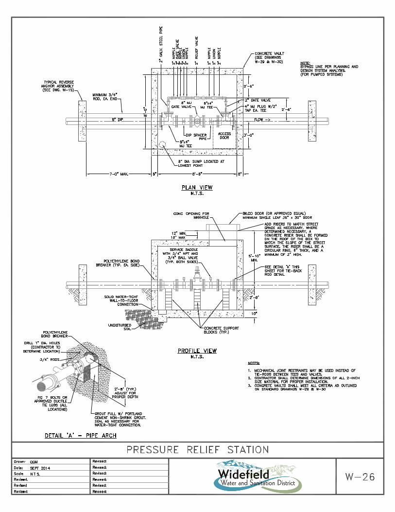


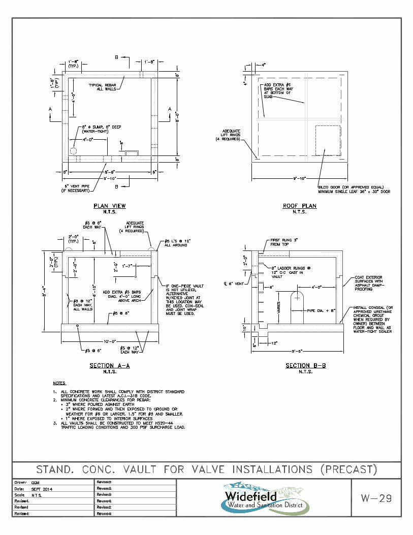


Sta
ndard
Dra
win
gs – W
ast
ewate
r


MECHANICAL JOINT CONNECTION
SLIP JOINT CONNECTION

TAPE
PLASTIC
TUBING
POLYETHYLENE
OF THE STANDARD SPECIFICATIONS.
TOP OF PIPE AND TAPED IN PLACE.
BE NEATLY DRAWN UP AROUND THE PIPE BARREL, FOLDED ON
COVERING THE PIPE SHALL BE LOOSE. EXCESS MATERIAL SHALL
PLASTIC ADHESIVE TAPE. THE POLYETHYLENE TUBE MATERIAL
OVERLAP FIRST TUBE WITH ADJACENT TUBE AND SECURE WITH
STEP 3:
PIPE
TUBING
POLYETHYLENE
PIP
E
O
V
E
R
L
A
P
2
'
M
I
N
.
FIELD INSTALLATION OF POLYETHYLENE WRAP
JOINT OF PIPE PRIOR TO WRAPPING AS PER SECTION 6.02(d)
TUBE IN PLACE. INSTALL BONDING STRAP OR WIRE AT EVERY
SPIGOT END AND WRAP WITH TAPE TO HOLD THE PLASTIC
TO END AT JOINT. FOLD MATERIAL AROUND THE ADJACENT
PULL TUBE OVER THE LENGTH OF THE PIPE. TAPE TUBE
PRIOR TO LOWERING IT INTO TRENCH.
PLACE TUBE OF POLYETHYLENE MATERIAL ON PIPE
STEP 1:
STEP 2:
PIPE
POLYETHYLENE
TUBING
2-#6 COATED (PE) COPPER BONDING
WIRE THERMOWELDED TO PIPE,
BOTH ENDS, OR BONDING STRAP
THERMO WELDED TO PIPE.
NO COMMON WELDS ALLOWED