wastewater treatment technologies – a basic guide · wastewater treatment technologies – a...
TRANSCRIPT

1
WASTEWATER TREATMENT TECHNOLOGIES – A BASIC GUIDE
WRC Report No. TT 651/15 ISBN 978-1-4312-0725-1

2
Obtainable fromWater Research Commission
Private Bag X03Gezina, 0031
[email protected] or download from www.wrc.org.za
The publication of this report emanates from a project entitled Wastewater Treatment Technologies – A basic guide (WRC Project No.
K8/1106).
DISCLAIMER
This report has been reviewed by the Water Research Commission (WRC) and approved for publication. Approval does not signify that
the contents necessarily reflect the views and policies of the WRC nor does mention of trade names or commercial products constitute
endorsement or recommendation for use.
© Water Research Commission

3
2.1 Sewers 2.2 Industrial discharge 3.1 Screening 3.2 Grit removal 3.3 Waste disposal options for screenings and grit 4.1 Flow measurement 4.2 Pond systems 4.3 Wetlands 4.4 Sedimentation 4.5 Flotation 5.1 Attached growth treatment technologies 5.2 Suspended growth treatment technologies 5.3 Nutrient removal activated sludge processes 5.4 Other treatment processes 5.5 Constructed wetlands 5.6 Ecosystem technologies 6.1 Chemical disinfection 6.2 UV radiation 6.3 Maturation ponds 7.1 Thickening 7.2 Stabilisation 7.3 Dewatering
3
WASTEWATER TREATMENT TECHNOLOGIES – A BASIC GUIDE
Index

4
1. Introduction to the GuidelineThe National Water Act, 1998 (Act 36 of 1998) (NWA) states that sustainability and equity are central guiding principles in the protection, use, development, conservation, management and control of water resources. In essence the use of water and development aspects need to be managed or controlled in such a manner to protect and conserve water resources.
Wastewater treatment works (WWTW), more commonly referred to as sewage works, are just one of the many uses of water that are required when development takes place. In order to ensure that the development takes place in a manner that will be sustainable the WWTW chosen needs to be a technology type that will be suitable for a particular development and not necessarily the best available technology.
PURPOSE OF THE GUIDELINESeveral Water Research Commission (WRC) reports have been compiled on wastewater treatment including: • Wastewater Risk Abatement Plan - A W2RAP
Guideline • Guidelines for the utilisation and disposal of
wastewater sludge• Guidelines for the inspection of wastewater
treatment works • Guideline Document: Package plants for the
treatment of domestic wastewater • Sanitation design manual • Energy Efficiency in the South African Water
Industry; and• Process design manual for small wastewater works
The need for a basic guide to serve as a quick reference document has been highlighted. The purpose of the guide is therefore to graphically illustrate the journey of sewage from collection, conveyance, treatment and
discharge to the environment. The guide would include both the liquid and sludge components.
In this way its purpose is to enable those in decision-making positions, but who do not necessarily have a technical background, young engineers and inexperienced scientists who have just entered the field of wastewater treatment, to have a better understanding of the overall processes, terminology and reasons for wastewater treatment. In addition the tips in the guide around energy, legislative requirements and safety will help the reader ask relevant questions and make more informed decisions.
WHO SHOULD USE THIS GUIDELINE?• Decision-makers in a municipality who may not
have a strong technical background however have to attend meetings and make decisions, including the Mayor and Councillors; and
• Young Engineers and Scientists who have just entered the field of wastewater treatment.
Do you know that discharge of wastewater effluent to a water course or by irrigation is controlled by Government legislation, namely Chapter 4 of the National Water Act, 1998 (Act No. 36 of 1998)?
Do you know what type of authorisation your WWTW
needs to apply for?

5
Rural Areas
Agricultural
Catchment
Industrial
Urban Areas
Informal Areas
WWTP
Water Treatment Plant
A WWTW must be authorised and the authorisation will specify the volumes of wastewater effluent that can be irrigated to land, or
discharged to a water resource daily, the volume being limited by the quality of the effluent and the impact on affected water resources, land,
and health and safety of the population.

6
ComminutionGrit RemovalScreeningsOxidation
Ponds/Wetlands
Sedimentation
Flotation
TricklingFilter
AnaerobicTreatment
NeutralisationEqualisation Coagulation
Aerated Lagoons
PolishingTrickling Filter
ActivatedSludge
Filtration/Flotation
OzonationGAC
Adsorption
PowderActivated Carbon
Disinfection
Nitrification/dentrification
Disinfection
PhosphorusRemoval
Disinfection
Coagulants
ConstructedWetlands
ToRiver
SludgeTreatment
Acid or alkali
IndustrialWastewater
Spill Pond
DomesticSewage
Collection System (sewer)
PRELIMINARY TREATMENT PRIMARYTREATMENT
SECONDARYTREATMENT
TERTIARY TREATMENT
ToRiver
ToRiver
ToRiver
ToRiver
Chemicals
SludgeTreatment
Chemicals
Wastewater technologies range from simple to complex systems. It can incorporate some or a combination of technologies indicated in this figure.
WHAT CAN YOU EXPECT TO FIND IN THIS GUIDE?The following two illustrations give a broad overview of:
• The type of technology that can be used at the different phases of the treatment process train• Technology option types related to population number served or environmental requirements.

7
Less
th
an
5000
pe
Ran
ge
5 00
0-50
000
pe
Susp
end
ed g
row
thtr
eatm
ent
tech
no
log
yA
ttac
hed
gro
wth
tr
eatm
ent
tech
no
log
y
yes
no
Stri
ct N
rem
ova
l req
uir
emen
t;TN
< 2
0 m
g/L
Nit
rog
en r
emo
val
acti
vate
d s
lud
ge
pro
cess
es
yes
Pon
ds
and
w
etla
nd
s te
chn
olo
gy
Stri
ct N
rem
ova
l req
uir
emen
t;TN
< 3
0 m
g/L
Co
nve
nti
on
altr
ickl
ing
filt
erte
chn
olo
gy
Hig
h p
erfo
rman
cetr
ickl
ing
filt
erp
roce
sses
Stri
ct N
rem
ova
l req
uir
emen
t;TN
< 1
0 m
g/L
Stri
ct P
rem
ova
l req
uir
emen
t;P
< 1
.0 m
g/L
Stri
ct P
rem
ova
l req
uir
emen
t;P
< 1
.0 m
g/L
Pon
ds
wit
h n
itri
fyin
gw
etla
nd
an
d, o
rex
tern
al n
itri
fyin
gtr
ickl
ing
filt
er
Stri
ct N
rem
ova
l req
uir
emen
t;TN
< 2
0 m
g/L
Hig
h p
erfo
rman
cetr
ickl
ing
filt
erp
roce
ss w
ith
ch
emic
al P
rem
ova
l
Nit
rog
en a
nd
Pho
sph
oru
s re
mo
val
acti
vate
d s
lud
ge
pro
cess
es
no
no
yes
yes
no
no
yes
no
yes
yes
yes
yes
yes
A L
arge
r co
ntri
buti
ng
com
mun
ity
will
req
uire
a
mor
e so
phis
tica
ted
plan
t
Act
ivat
ed s
ludg
e pr
oces
s re
quir
ed fo
r TN
< 1
0 m
g/l
Hig
h pe
rfor
man
ce
tric
klin
g fil
ter
wit
h ch
emic
al p
hosp
horu
sre
mov
al t
o ac
hiev
e 10
<TN
<20
P <
1
Add
itio
nal c
onsi
dera
tion
s w
hen
choo
sing
a t
echn
olog
y op
tion
are
:-
ski
lls r
equi
rem
ents
- la
nd a
vaila
bilit
y-
gro
und
cond
itio
ns-
slu
dge
hand
ling
capa
bilit
ies,
and
- c
ost
(cap
ital
, O&
M a
nd li
fe c
ycle
)
No
te: O
ther
fac
tors
su
ch a
s ca
pac
ity
to m
anag
e th
e p
lan
t ar
e cr
itic
al
8
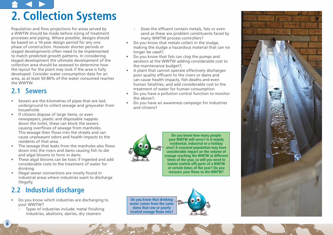
2. Collection SystemsPopulation and flow projections for areas served by a WWTW should be made before sizing of treatment processes and piping. Where possible, designs should be based on a 10-year design period for any one phase of construction. However shorter periods or staged developments often need to be implemented to match predicted growth patterns. In considering staged development the ultimate development of the collection area should be assessed to determine how the layout for the plant may look if the area is fully developed. Consider water consumption data for an area, as at least 50-80% of the water consumed reaches the WWTW.
2.1 Sewers• Sewers are the kilometres of pipes that are laid
underground to collect sewage and greywater from households
• If citizens dispose of large items, or even newspapers, plastic and disposable nappies down the toilet, these can block the sewers causing overflows of sewage from manholes. This sewage then flows into the streets and can cause unpleasant odors and health impacts to the residents of that area
• The sewage that leaks from the manholes also flows down into the rivers and dams causing fish to die and algal blooms to form in dams
• These algal blooms can be toxic if ingested and add considerable costs to the treatment of water for drinking
• Illegal sewer connections are mostly found in industrial areas where industries want to discharge illegally.
2.2 Industrial discharge• Do you know which industries are discharging to
your WWTW? ◦ Types of industries include: metal finishing
industries, abattoirs, dairies, dry cleaners
◦ Does the effluent contain metals, fats or even sand as these are problem constituents faced by many WWTW process controllers?
• Do you know that metals collect in the sludge, making the sludge a hazardous material that can no longer be used?;
• Do you know that fats can clog the pumps and aerators at the WWTW adding considerable cost to the maintenance budget?;
• A plant that cannot operate effectively discharges poor quality effluent to the rivers or dams and can cause health impacts, fish deaths and even human fatalities, and add considerable cost to the treatment of water for human consumption
• Do you have a pollution control function to monitor the above?;
• Do you have an awareness campaign for industries and citizens?
Do you know how many people your WWTW will serve? Is it mainly residential, industrial or a holiday
area? A seasonal population may have considerable impact on the volume of
sewage reaching the WWTW at different times of the year, so will you need to isolate (switch off) parts of a WWTW at certain times of the year? Do you measure your flows to the WWTW?
Do you know that drinking water comes from the same
dams that raw or poorly treated sewage flows into?

9 9
WASTEWATER TREATMENT TECHNOLOGIES – A BASIC GUIDE
3. Preliminary Treatment3.1 ScreeningMaterials such as rags, plastic and foreign materials can significantly interfere with the treatment processes or damage the plant equipment if not removed. These materials are removed by means of screening. The screened materials are hazardous and must be safely disposed of to prevent human health concerns, fly breeding and odours. Screens may be mechanical or manual.
• Manual screens: little or no equipment maintenanceand provide a good alternative for smaller plantswith few screenings but need to be cleaned moreregularly to prevent the build-up of debris;
• Mechanical screens: lower labour costs andimproved flow conditions and screening capture,however can have high equipment maintenancecosts. Require constant energy supply.
3.2 Grit removalGrit material can include sand, silt, glass, small stones as well as other large-sized organic and inorganic substances (detritus). Excess grit can cause operational problems such as pump blockages and high organic concentrations in the digesters and/or reactors. Grit removal is therefore essential to protect moving mechanical equipment and pumps from abrasion.
Comminution is the reduction of solid materials from one average particle size to a smaller average particle size by crushing, grinding, cutting, vibrating, or other processes.
3.3 Waste disposal options for screenings and gritScreenings and grit left lying around will cause nuisance conditions such as odours and will encourage fly breeding. It should therefore be disposed of into a suitable container such as a large dustbin that can be closed. It is important to ensure that no screenings are left lying around on the ground. At small WWTW screenings and grit can be buried in trenches. These trenches must immediately be covered with soil once screenings and grit have been disposed of.
Did you know that where larger volumes of screenings and grit are collected,
legislation requires the screenings and grit to be disposed of to a permitted
landfill site?

10
4. Primary Treatment4.1 Flow measurementChanges in the volumes entering the plant will alert the Process Controller to possible problems upstream of the works, e.g. a pump station failure. It is also important to know when the peak flow arrives at the WWTW. Flow is typically measured just after the screens and grit removal processes and it is important to note that one of the conditions of an authorisation will be that the flow is measured.
Flow balancing, also called flow equalisation, is used to overcome the operational problems caused by flow rate variations and to improve the performance of the downstream unit processes. In other words, flow balancing is simply the damping of flow rate variations so that a constant or nearly constant flow rate can be achieved.
Balancing tanks can be located before or after primary sedimentation. If placed after primary sedimentation, fewer problems with sludge and scum occur. If placed before primary sedimentation, mixing must be in place to prevent solids deposition and aeration may be needed to prevent odours.
4.2 Pond SystemsPond systems are simple, low maintenance systems requiring large footprint areas. They should be considered where the cumulative impact of a number of wastewater treatment works is low. Ponds are extremely flexible. Pond effluent can be treated to meet irrigation standards for land applications, or coupled with other advanced treatment technologies could meet discharge standards that may be set.
4.2.1 Anaerobic ponds (Opposite page)
• Deep structures typically 4-5 m deep, so require lessspace
• Can be arranged in parallel cells configuration withalternating wastewater feed pattern or series cellconfiguration feeding from first cells
• Achieve solids separation and with production ofexcess sludge, which is well stabilised and can beused beneficially in accordance with the SludgeGuidelines (www.wrc.org.za);
• Applicable at small and large scale• Low investment costs• No, or very low, energy demand• Cannot be discharged and would require follow-on
treatment but good first stage process.
4.2.2 Conventional Pond system (Opposite page)
Conventional pond systems typically contain high algal solids and depending on time of year may contain high residual nitrogen and phosphorous. The algae are small water plants using the energy of sunlight to utilise carbon dioxide to build plant cells, produce oxygen preventing the ponds from turning anaerobic. These ponds are generally non-discharge ponds but effluent could be used for irrigation of crops that are not consumed raw.
Aerated ponds/lagoons could be created when aerators are added.
• An energy source would then be requiredDid you know that flow measurement
is a legal requirement and can improve your Green Drop score?
0
Flow
rate
2
An example of the flow of sewage entering a WWTW each day showing why a balancing tank may be
important to “Flatten” the load
4 6 8 10 12 14 16 18 20 22 24

11 11
WASTEWATER TREATMENT TECHNOLOGIES – A BASIC GUIDE
ANAEROBIC PONDS Features:• Deep structures, typically 4 to 5 m
deep• Achieve solids separation and some
stabilisation• Can be arranged in parallel cells
configuration with an alternatingwastewater feed pattern or series cellconfiguration feeding from first cell
CONVENTIONAL POND SYSTEM
Pretreated(screened)
Wastewater
Oxidation Ponds
WasteSludge
Pond Effluent
FacultativePond(s)
Recycle Pumps(optional)
Typically contains high algal solids and depending on time of year may contain high residual nitrogen and phosphorous. These ponds are generally non-discharge ponds.
PretreatedWastewater
PretreatedWastewater
SludgeWithdrawal
Sludge Withdrawal
Sludge Withdrawal
SludgeWithdrawal
DownstreamTreatmentProcesses
DownstreamTreatmentProcesses
PARALLEL CELL CONFIGURATION
SERIES CELL CONFIGURATION

12
4.2.3 High performance pond systems (below)
Produces better water quality compared to a conventional pond system. A high performance pond system would consist of a conventional pond system with additional features such as:
• Trickling filter to achieve nitrification• Polishing wetlands that would achieve a better
quality effluent that could be discharged• Possibility of propagating fish in the final ponds to
eat mosquito larvae and also be a food source• May be an attraction to water birds• Algae could be floated off and used as animal
feed or incorporated into compost for agriculturalpurposes.
Emerging
High rate algal ponds (HRAP) with tertiary treatment can meet irrigation and General Authorisation limits.
4.2.4 Ponds integrated with other advanced technologies
There are many opportunities to upgrade pond systems. These systems are often a result of upgrading of conventional ponds. Common systems include:
• Anaerobic ponds followed by trickling filters• Petro process which consists of anaerobic ponds
-> oxidation ponds -> tricking filters or activatedsludge treatment
• Maturation ponds downstream of secondarytreatment processes.
Examples of these configurations are shown on the opposite page. Would also require:
• Electricity supply• Moderate maintenance.
Produces better water quality compared to a conventional pond system. A high performance pond system would consist of a conventional pond system with additional features.Pretreated
(screened) Wastewater Oxidation Ponds
WasteSludge
Pond Effluent
FacultativePond(s) Recycle
Pumps
PolishingWetlands
Ferric/Alum
NitrificationTrickling Tank
HIGH PERFORMANCE POND SYSTEM
• Would require energy forpumping and aeration
• If HRAP, the energyrequirements would belowered for movement ofliquid.
High rate algal ponds (HRAP)
WRC TT 390/09

13 13
WASTEWATER TREATMENT TECHNOLOGIES – A BASIC GUIDE
ANAEROBIC POND INTEGRATED WITH A SECONDARY TREATMENT PROCESS
Feed Wastewater
DigestedSludge
TreatedWastewater
AnaerobicPonds
Trickling Filter
HumusClarifier
Oxidation Pond
HumusSludge
Pretreated Wastewater
WasteSludge
PlantEffluent
AnaerobicPonds Trickling
Filter
Humus SludgeRecycle
HumusClarifier
Disinfection
TFE Recycle
TRICKLING FILTER INTEGRATED WITH PONDS

14
PARAMETERSANAEROBIC POND
TREATMENT SYSTEMCONVENTIONAL POND TREATMENT SYSTEM
ENHANCED POND TREATMENT SYSTEM
AERATED LAGOONS
Application range/niche
While applicable over a wide range of sizes, typically used more in micro- to small plants category. Requires large footprint area. Advantage if natural materials of construction with low permeability available at/near plant site.
Geotechnical site conditions must be favourable for bulk earthworks construction. Plant site should preferably be away from residential areas.
Smaller communities with treatment plant capacity ≤ 0.5 to 2 Mℓ/day.
Pond effluent disposal requires special attention, such as available land.
Smaller communities with treatment plant capacity ≤ 0.5 to 5 Mℓ/day.
Pond effluent disposal requires special attention, but may satisfy discharge standards if designed and operated correctly.
Aerated lagoons typically applied as an upgrade strategy to conventional pond systems.
More common in some industrial effluent treatment than in domestic wastewater systems.
Operational require-ments
Minimum operator intervention required regularly. Odour generation must be mitigated. Periodic desludging required.
Simple operational requirements including:• adjustments of flow division/
split• vegetation control and site
clearing• routine sampling and
monitoring • control of nuisance insects such
as mosquitoes.
Simple operational requirements including:• adjustments of flow division/split• vegetation control and site
clearing• routine sampling and monitoring.
Additional operational requirements related to recycle streams: • pump control• recycle stream treatment• chemical dosing.
Simple operational requirements including:• adjustment of flow division/split• routine sampling and monitoring
Additional operational requirements related to the floating mechanical aerators.
Maintenance require-ments
Desludging may require mobile pumps.
Materials of construction to be resistant to high levels of H2S.
No mechanical/electrical equipment and instrumentation to maintain.
Recycle pump maintenance may be required, if installed.
Some simple mechanical/electrical equipment maintenance require related to: • recycle pumps• recycle treatment system.
Floating mechanical aerators are a high maintenance burden.
Routine and preventative maintenance is cumbersome due to restricted access to these machines.

15 15
WASTEWATER TREATMENT TECHNOLOGIES – A BASIC GUIDE
4.3 WetlandsBased on their ability to clean water, wetlands are often used as a tertiary treatment for the treatment of wastewater. These may be natural systems to which an effluent of a particular quality is discharged, or even a constructed (man-made) wetland.
In essence, wetlands are filters where sediments and nutrients accumulate. This nutrient-rich sediment encourages the growth of plants such as bulrushes, grasses, reeds, waterlilies, sedges and trees which provide food and a place for attachment and shelter for many creatures. Some animals are completely dependent on wetlands; others use wetlands for only part of their life cycle, such as for breeding.
Wetland systems treat water that passes through it by filtration, settling, and bacterial decomposition. Wetlands play an important role in regulating the movement of water and by definition, are characterised by water saturation in the root zone, at, or above the soil surface, for a certain period of time during the year.
Wetlands may be a sink for, or transform, nutrients, organic compounds, metals and components of organic matter. Wetlands may also act as filters of sediments and organic matter and may become a permanent sink for these substances if the compounds become buried in the substrate or are released into the atmosphere. These chemical substances may also only retain them during the growing season or under conditions of flooding. Wetland processes play a role in the carbon, nitrogen, and sulphur cycles by transforming them and releasing them into the atmosphere. Wetlands are therefore very important in assisting with removing contaminants (water quality) as well as in erosion control.
Did you know that not only do wetlands play an essential part in helping with the regulation of the flow of water by slowing it down, they are also filters and help to clean water by filtering pollutants which may then be retained by the wetland plants, allowing cleaner water to flow through to the river? In addition wetlands are very important habitats for many fish, insects and other animals.

16
4.4 Sedimentation
The main purpose of primary sedimentation is to allow separation of the solid and liquid phase fractions in the wastewater. It removes the readily settleable solids which are mainly organics as well as the floating material such as fats, oils and grease. The settled solids are known as primary sludge. The process therefore reduces the suspended solids content of the influent wastewater. Even though the volume of primary sludge is only about 2% of the total influent wastewater volume, it makes up approximately 30 to 40% of the organic load received (expressed as COD) and some 40 to 60% of the suspended solids loading.
4.5 FlotationFlotation is a process that involves producing small air bubbles in the wastewater being treated. The bubbles would attach to solid particles. The resulting bubble-solids agglomerates are buoyant and so float to the surface of the water where they accumulate as a floating layer of sludge, known as float, before being removed by a scraper and being disposed. It is commonly known as dissolved air flotation (DAF). Flotation has a high operational cost because it requires a great deal of energy to keep the aerators running.
5. Secondary Treatment5.1 Attached Growth Treatment Technologies
Aerobic attached-growth treatment processes are those processes that utilise microorganisms that grow on a
medium, such as stones and discs, to remove organic matter found in wastewater. They can also be used to achieve nitrification – the conversion of ammonia to nitrate/nitrite.
5.1.1 Rotating Biological Contactors (Opposite page)
These aerobic attached-growth treatment processes are also known as disk systems as they consist primarily of a set of disks, made of some man-made material mounted on a shaft that is mounted over the wastewater that is being treated. The shaft needs to rotate slowly so that the disks are immersed in the wastewater for a short period of time before returning to the air. This ensures that a biological slime develops on the disks in a manner similar to that of the biological filter. In time, this slime falls off and falls into the wastewater where it has to be settled out and removed/recycled.
• Requires electrical supply• Moderate maintenance
5.1.2 Trickling Filters (Opposite page)
Trickling filters also referred to as biofilters, are used to remove organic matter from wastewater. The trickling filter is an aerobic treatment system that utilizes microorganisms attached to a medium to remove organic matter from wastewater. Trickling filters enable organic material in the wastewater to be adsorbed by a population of microorganisms (aerobic, anaerobic, and facultative bacteria, fungi, algae, and protozoa) attached to the medium as a biological film or slime layer (approximately 0.1 to 0.2 mm thick). As the wastewater flows over the medium, microorganisms already in the water gradually attach themselves to the rock, slag, or plastic surface and form a film. The organic material is then degraded by the aerobic microorganisms in the outer part of the slime layer.
• Electrical supply needed• Moderate maintenance

17 17
WASTEWATER TREATMENT TECHNOLOGIES – A BASIC GUIDE
ROTATING BIO-CONTACTOR
A rotating bio-contractor consists of a horizontal shaft with multiple plastic discs onto which the microorganisms attach. These are typically found in smaller applications. Excess biomass falls off as the disc rotates.
PretreatedWastewater
Septic Tank (optional)
TreatedWastewater
RBC Tank
HumusClarifier
Sludge Recycle(optional)
Waste Humus Sludge
TRICKLING FILTERS
Trickling filters, also referred to asbiofilters, consist of an open structure packed with media, allowing wastewater to filter through.
The media can consist of graded natural stone, randomly packed synthetic material or structured synthetic material.
FeedWastewater
TreatedWastewater
Trickling Filter
HumusClarifier
TFE RecycleHumus Sludge
PrimraryClarifier
PrimarySludge

18
5.2 Suspended Growth Treatment TechnologiesThe activated sludge process (ASP) is a biological process of developing an activated mass of microorganisms capable of stabilizing waste aerobically. Organic waste is introduced into a reactor where a bacterial culture (biomass) is maintained in suspension. The reactor content is referred to as the ‘mixed liquor’ or activated sludge.
Did you know that visual observation of the ASP is very important? The colour, smell and appearance of the biomass give a good indication of whether the ASP is working well or not. An ASP that is working well will have a dark brown biomass with an earthy smell and will have very little scum on the surface.
There are numerous configurations that can be applied when designing an ASP, however each configuration has unique design and operational specifications that must be adhered to in order to produce a good quality effluent that can be discharged to the environment and have a minimal impact on downstream users.
When running an ASP it is important to have either on-line or hand-held instrumentation available to test the various parameters that will help to optimise the operations. This instrumentation must however be properly calibrated to give the correct answers. One such example is the measurement of dissolved oxygen which, if maintained at an optimal level, will help to:
• Save energy by avoiding excessive input of oxygen• Remove nitrogen and phosphates from wastewater,
one of the prime objectives of wastewater treatment • Produce a sludge with good settling characteristics
and • Improve final effluent quality.
Skilled process controllers are needed to run the ASP.The maintenance and operational costs to run an ASP are high.
Safety
Because of the mechanisation of ASPs and the electrical
and moving equipment needed to run the plant, safety is very important. In terms of the Occupational Health and Safety Act, it is important to have visible safety signs. ASP may also require chemical dosing, it is therefore important to keep chemicals safely and correctly stored to avoid health and safety incidents. To comply with the OHSA, PPE (personal protective equipment), i.e. overalls, safety shoes, hard hat and gloves should be worn as required.
Apart from the normal safety precautions, such as the provision of first aid material, there must be safety equipment such as:
• Buoys with an adequate length of rope placed at strategic positions in the activated sludge plant. The one length of the rope should be tied to a fixed object so that it would be possible to retrieve a person from the basin
• Earmuffs should be worn in all blower houses for diffused air plants and suitable notices should be up
• Masks, when working in an enclosed chlorine contact room
• Fences should be up to prevent persons and animals from entering the site
• Illumination of dangerous areas at night is important to prevent accidents
• Masks should be available if there is excessive spray.
Energy management
Costs can be saved by process optimisation and investing in the correct aeration design.
Did you know that the ASP is extremely energy intensive and requires an uninterrupted supply of electricity to work optimally especially for aeration?
Aeration = 50-70% of energy
consumption
Pumping
Lighting &
buildingsClarifiers
Belt press
Anaer digester

19 19
WASTEWATER TREATMENT TECHNOLOGIES – A BASIC GUIDE
5.2.1 Nitrogen removal Activated Sludge Processes
The nitrogen removal ASP involves biological nitrogen removal, in which two biological processes are used: nitrification and denitrification. Nitrification is a two-step microbiological reaction in which ammonia nitrogen is converted into nitrite by Nitrosomonas bacteria and subsequently into nitrate by Nitrobacter bacteria. In the denitrification process the produced nitrate is converted into harmless nitrogen gas. Nitrogen is present in wastewater in several forms, the important ones being organic nitrogen (both soluble and particulate), ammonium/ammonia and possibly some nitrate. In the activated sludge process several reactions may occur, that will change the form of the nitrogenous matter via ammonification, nitrification and denitrification.
For this reason nitrification is a requirement of South African effluent standards and both ammonia and nitrate must be measured in the final effluent.
5.2.1.1 Modified Ludzack-Ettinger (MLE)
The modified Ludzack-Ettinger process includes an aeration tank which is split into two compartments: one being un-aerated but mixed, and the other aerated and mixed. Ammonia and reduced nitrogen are oxidized in the aerobic compartment of the BNR reactor.
5.2.1.2 Oxidation ditch activated sludge with alternating aerobic and anaerobic zones
The oxidation ditch activated sludge process has an oxidation ditch which is typically constructed as relatively shallow, broad channels in which the biomass is kept in suspension by brushes and other mechanical devices. The oxidation ditch has different sections of aerated and un-aerated sections through which the liquor passes.
Did you know that if ammonia is not converted to nitrates within the ASP, the conversion will take place in the receiving water body (the river or dam) using up available dissolved oxygen and creating an oxygen shortage in the water leading to fish kills!
Molecular Nitrogen gas (N2)Boundary of activated
sludge system
Nitrogen in the effluent
(dissolved)Influent nitrogen:
Nitrogen in excess sludge (Nl) (solid)
Nitrification
DenitrificationNitrate
Ammonification
Ammonium
Organic nitrogen
Assimilation

20
5.3 Nutrient Removal Activated Sludge Processes
The 3-stage Bardenpho is the most commonly applied BNR activated sludge process in South Africa. Variations of this process include:
• Johannesburg BNR process• UCT and modified UCT activated sludge process• Five stage Bardenpho process.
5.3.1 3-Stage Bardenpho
The 3-stage Bardenpho process BNR reactor is split into three distinct compartments for phosphate removal, nitrogen removal and COD oxidation. RAS (return activated sludge) from the clarifiers, which has low nitrogen concentrations, enters the anaerobic compartment, stimulating the phosphate accumulating organisms to release phosphate as a source of energy.
The Johannesburg modification of this process includes a separate RAS denitrification compartment to reduce any residual nitrate in the RAS by endogenous decay, which further improves phosphorous removal in the anaerobic compartment.
5.3.2 UCT/Modified UCT
The University of Cape Town (UCT) modification has a different method of dealing with the residual nitrate concentration in the RAS. The RAS is first recycled to the upstream end of the anoxic compartment, using available carbon flowing from the anaerobic section to reduce residual nitrate.
This denitrified liquor is then recycled back to the anaerobic compartment.
5.3.3 5-Stage Bardenpho
In the 5-stage Bardenpho process, the BNR reactor has 5
compartments with anaerobic, primary anoxic, aerobic, secondary anoxic and re-aeration zones. The two anoxic compartments optimize nitrogen reduction.
5.4 Other treatment processes5.4.1 Membrane separation biological
treatment (MBR)
The use of permeable membranes to separate the mixed liquor suspended solids is performed in many different process configurations. The main components include:
• Pre-treatment with at least fine screening and gritremoval
• Biological reactor• Membrane tanks, containing micro- and/or ultra-
filtration units• Liquor recycles from the membrane tanks back to the
biological reactor.
If gravity separation is to be used, very large clarifiers are needed, and even then it is still sensitive to poor sludge settleability.
Potential benefits of the Membrane Bioreactors process include:
• Smaller biological reactor, since the process can beoperated at higher concentrations of suspendedsludge
• High quality treated wastewater• Existing plant structures can be retrofitted without
increasing the reactor tankage• Reduced sludge production.
5.4.2 Emerging variations
Granular sludge system is an emerging system but requires good process control to maintain the granules.

21 21
WASTEWATER TREATMENT TECHNOLOGIES – A BASIC GUIDE
PretreatedWastewater
TreatedWastewater
WasteSludge
Option
PrimraryAnoxic
RAS Pumps
Membrane Tank
Aerobic
Membrane Biological Reactor
Anaerobic
NO3-N-Recycle
SecondaryAnoxic
Sludge Respiration
Permeate Pumps
Recycle
Air Compressor

UV
22
5.4.3 DEWATS
DEWATS stands for: decentralised wastewater treatment systems. DEWATS aim to use local materials in design but at the same time following rigorous technical norms. It tries to be as low in energy intensity as possible and in favourable circumstances the whole treatment process of wastewater can be completely gravity driven without any energy requirement at all. This means that power cuts and load shedding or even accidental switching off of motors or pumps do not come into the picture at all. Wastewater flows as low as 100 litres or 1 cubic metre (m3) to as high as 1 000 m3 can be handled by DEWAT systems. There is little or no maintenance though the performance has to be monitored regularly.
A typical system for a domestic household consists of:
• a primary treatment system consisting of a settling andfloating tank
• a secondary treatment system of an up-flow type baffledreactor which digests wastewater anaerobically
• a tertiary treatment in subsurface horizontal flow sandfilters with reed beds; and
• a polishing pond for oxygenation and UV disinfectionfrom the sun’s rays.
The treatment of wastewater is highly effective and consistently meets pollution norms. Since the baffled reactors work very well, there is complete digestion of solids and usually there are no emptying or cleaning requirements unlike a septic tank. The quality of treated wastewater that emerges into the polishing pond is good enough for landscape applications. The reed bed system in the filter part can be a very good landscape feature with plants like canna offering a colourful and verdant look.
The DEWATS approach reports a 80 to 85 per cent reduction in BOD and COD, a 80 per cent reduction in phosphates and a 60 per cent reduction in ammonia from the input wastewater.
Waste water
Constructed Wetlands Polishing ponds
Primary treatment(for example:)• Sedimentation ponds;• Septic tanks;• Imhoft tanks
Secondary treatment(for example:)• Baffled septic tank;• Fixed filters
Research is showing that the N+P found after the anaerobic baffle reactors can be used to successfully improve plants yields for agriculture.

23 23
WASTEWATER TREATMENT TECHNOLOGIES – A BASIC GUIDE
5.4.4 PETRO
The acronym PETRO stands for Pond Enhanced Treatment and Operation. The PETRO system is an appropriate technology equally applicable in the developed and developing world. It combines waste stabilisation ponding as a low tech primary stage and a polishing facility as a secondary stage. The secondary stage (PETRO facility) can either be a trickling filter or an activated sludge process.
The primary pond, a relatively low-cost facility, makes a major contribution to the biological breakdown of organic matter (60% of COD removal) and therefore the overall economy of the system. The effluent from this pond is split and goes to the PETRO facility/reactor which is either a trickling filter or activated sludge process and to the secondary pond (oxidation pond) via a sidestream. The secondary pond allows the process of biological
degradation of residual matter to continue. From this pond there is an algal-rich recycle back to the primary pond that will help to minimise methane production by introducing oxygen.
• The PETRO trickling filter variant: larger capital outlaybut less operational and maintenance costs and is verysimple to operate
• The PETRO activated sludge variant: inexpensivecapital-wise, however compared to the trickling fillerexerts a larger electricity demand and requires moreattention from the staff with skills to run a moresophisticated plant.
The activated sludge variant offers a substantial additional advantage as, if necessary, it can be extended at little extra cost to facilitate pronounced biological phosphorus removal.
Raw sewagePrimary
pondSecondary
pond
PETRO facility*
* PETRO facility is either an activated sludge reactor or trickling filter.
Sidestreaming
Clarifier

24
5.4.5 Packaged plants
What is a package plant? A package plant is any onsite, waterborne, domestic wastewater treatment system; whether it consists of one or many modules; with a total capacity less than 2 000 m3/day. It typically includes equipment largely constructed and packaged off site and brought onsite for installation.
Several package treatment technologies exist for the treatment of domestic wastewater. The most common types installed in South Africa include:
• Activated sludge/extended aeration plant• Trickling filter• Submerged bio-contactors; and• Rotating bio-contactors.
Systems which usually form the pre-treatment step or polishing step include:
• Purely anaerobic systems• Pond systems; and• Constructed wetlands.
Disinfection is necessary for destroying pathogens in the treated wastewater before release to the environment. Disinfection is the final step in the treatment process and it is essential that the water is adequately treated prior to this step in order to ensure that the disinfection step is effective.Common methods of disinfection include:
• Chlorination• Ozonation; and• Ultraviolet radiation.
Other disinfection methods available but are often not practical for onsite applications due to the hazardous nature of the chemicals used or the complexity of the process.
Did you know that chlorine gas is toxic and requires special equipment and trained personnel to work with and is not suggested for use in package plants? The disinfection method selected should be safe, reliable, simple and cost effective.

25 25
WASTEWATER TREATMENT TECHNOLOGIES – A BASIC GUIDE
5.4.5.1 Activated sludge plants/extended aeration
In most cases, these systems consist of a septic tank, followed by an aerated tank, a clarifier and a disinfection tank.
5.4.5.3 Membrane bioreactors
Membrane bioreactors, including submerged membrane bioreactors, are a relatively new technology in South Africa. These reactors make use of the activated sludge process, but in a modified form. The clarifier step is replaced by semi-porous membranes arranged is sheets or tubes. The membranes can be costly and it is therefore important to screen wastes in membrane type bioreactors. Membrane systems can produce a high quality effluent, suitable for reuse applications or feed to reverse osmosis treatment.
5.4.5.2 Emerging trends - Anammox
As an emerging technology, Anammox wastewater treatment offers the possibility of replacing the nitrification and denitrification processes for removing ammonia nitrogen from wastewater with partial nitrification and the anammox bacterial reaction which produces nitrogen gas. This reduces the power requirements and sludge output.
Influent
Influent
Septic Tank
Septic TankMembrane Bioreactor
Disinfection
Screens
Aeration Tank ClarifierDisinfection Tank
Final Effluent
Sludge for Disposal

26
5.4.5.4 Submerged bio-contactors
Plastic media, which allows for biomass attachment, is used in Submerged Bio-Contactors (SBC). The primary treatment, in most cases, consists of a septic tank. The wastewater is then pumped to a bio-contactor tank, which is filled with the plastic media. Air is introduced to the tank by means of an aeration blower. Several package plant manufacturers in South Africa use the SBC approach. These systems have variations, but employ a similar concept of placing plastic media in a tank to allow surface area onto which the biomass can attach. Adequate aeration is critical to the performance of these treatment systems.
5.4.5.5 Trickling filters
Trickling filters are similar to the SBCs in that a tank is filled with a rock or synthetic media to allow for biomass attachment. The wastewater is sprayed at the top of the media surface and the tank is open to the atmosphere allowing for natural ventilation and aeration. As the wastewater gravitates to the bottom, organic matter and ammonia are metabolized by the biofilm which forms on the media surface.
Influent
Influent
Septic Tank
Septic Tank
Trickling Filter Humus Tank
Blower (Aeration)
Bio-contactor Disinfection Tank
Disinfection Tank
Final Effluent
Final Effluent
Clarifier
27 27
WASTEWATER TREATMENT TECHNOLOGIES – A BASIC GUIDE
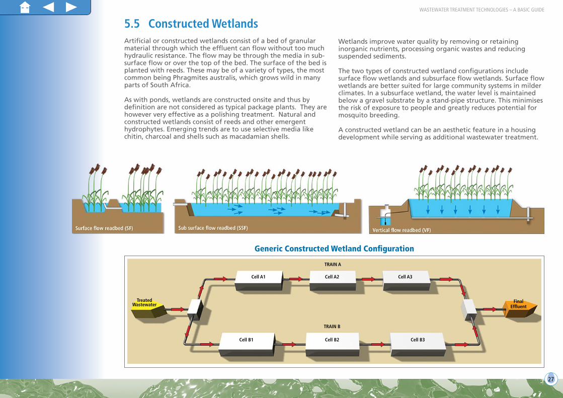
5.5 Constructed WetlandsArtificial or constructed wetlands consist of a bed of granular material through which the effluent can flow without too much hydraulic resistance. The flow may be through the media in sub-surface flow or over the top of the bed. The surface of the bed is planted with reeds. These may be of a variety of types, the most common being Phragmites australis, which grows wild in many parts of South Africa.
As with ponds, wetlands are constructed onsite and thus by definition are not considered as typical package plants. They are however very effective as a polishing treatment. Natural and constructed wetlands consist of reeds and other emergent hydrophytes. Emerging trends are to use selective media like chitin, charcoal and shells such as macadamian shells.
Wetlands improve water quality by removing or retaining inorganic nutrients, processing organic wastes and reducing suspended sediments.
The two types of constructed wetland configurations include surface flow wetlands and subsurface flow wetlands. Surface flow wetlands are better suited for large community systems in milder climates. In a subsurface wetland, the water level is maintained below a gravel substrate by a stand-pipe structure. This minimises the risk of exposure to people and greatly reduces potential for mosquito breeding.
A constructed wetland can be an aesthetic feature in a housing development while serving as additional wastewater treatment.
Generic Constructed Wetland Configuration
TreatedWastewater
Cell A1 Cell A2 Cell A3
Cell B1 Cell B2 Cell B3
TRAIN B
TRAIN A
FinalEffluent

28
5.6 Ecosystem technologiesEcosystem technologies for treating water are designed along the principles evolved by nature for building and regulating ecologies such as forests, lakes, estuaries and wetlands whose primary energy source is sunlight. Like natural ecosystems, ecosystem technologies have hydrological and mineral cycles. To create an ecosystem technology such as a living machine, organisms are collected and reassembled in unique ways depending on the purpose of the project. Appropriate assembly, depending on context is based on knowledge of the specific organisms that make up the components of the system, and on an understanding of the relative ecological context and ways to combine the individual components to achieve the desired function.
John Todd Ecological Designs,
web-site: toddecological.com
In practical application, ecosystem technologies are self-contained treatment systems designed to treat a specific waste stream using the principles of ecological engineering. They achieve this by using diverse communities of bacteria and other microorganisms, and some combination of algae, plants, trees, snails, fish and other living creatures.
Did you know that plants help to reduce contamination and eliminate odours?
6. Disinfection6.1 Chemical disinfection6.1.1 Chlorination
Chlorine, which has been used as a disinfection method for both water and wastewater for many decades, can be added as a gas, liquid or solid in the form of sodium or calcium hypochlorite.
Overdosing is an ecological risk and thus discharge to long grass swales/ditches or wetlands is recommended
prior to direct discharge into sensitive water resources. Under dosing on the other hand poses a health risk in terms of residual pathogen exposure to humans. It is therefore important to follow the necessary precautions prescribed when working with chlorine and ensure that all staff and operators are trained accordingly.
6.1.2 Ozonation
Ozone is becoming more popular with package plant distributers. Ozone dissociates rapidly and is therefore produced on site. Remaining ozone in the off gas is destroyed before release to the atmosphere, and it is thus better to ensure optimal ozone dosage for
overall efficiency. Disinfection depends on dosage, mixing and contact time. It is critical that an ozone disinfection system is pilot tested and calibrated prior to installation on site.
6.2 UV RadiationUltraviolet (UV) radiation disinfection is not common in South Africa amongst package plant distributors. The effectiveness of UV disinfection is dependent on the characteristics of the treated effluent transmissivity, the intensity of the UV radiation and the amount of time that the microorganism is subjected to the radiation.
Some examples include combinations of: • Floating islands which could be set out
in a particular pattern to intercept the contaminated water, such as an elongated island along a canal to which raw sewage is discharged
• Aerobic tanks filled with plants through which the wastewater is passed
• Artificial marshes/vlei• Aerated ‘ecosystem’ tanks including bacteria,
invertebrates, green plants from algae to trees, snails insects and fish
• Shallow ponds that use ultraviolet light for disinfection• Using greenhouses to house the various components,
especially where cold climates may impact on plant growth.

29 29
WASTEWATER TREATMENT TECHNOLOGIES – A BASIC GUIDE
Disinfection type Advantages Disadvantages
Chlorination
• It is a simple technology to apply• It has a long history of data showing success; and• Residual addition of chlorine in controlled measures prevents the spread of life
threatening diseases.
• Free chlorine and chlorine residuals have proved detrimental to aquatic life• Chlorine will react with organic materials to form trace concentrations of
trihalomethanes, suspected to be carcinogenic; and• Health risks of direct exposure to chlorine include:
• Irritation to mucous membranes, respiratory tract and eyes due to gaseous chlorine reacting with moisture to form hydrochloric acid
• Coughing, gagging, pulmonary oedema and even death when exposed to chlorine gas for prolonged periods; and
• Skin irritation, such as burns, from contact with liquid chlorine.
Ozonation
• Ozone is more effective than chlorine in the destruction of viruses and bacteria• The ozonation process requires relatively short contact times• Ozone decomposes rapidly, reducing the risk of harmful residuals remaining in the water• There is no re-growth of microorganisms after ozone treatment, except for those
protected by particulates• Sufficient quantities of ozone are generated on site as required, thereby eliminating the
risks associated with the transport and handling of a hazardous substance.
• Low dosages may not eliminate viruses, spores and cysts • Ozonation is a complex technology, requiring complicated equipment and
contacting systems• Turbidity in the treated effluent can render ozone disinfection ineffective• Ozone is extremely irritating and possibly toxic, and off gases from the ozone
contactor must be destroyed; and• The cost of treatment can be high in terms of capital investment and power
consumption.
UV radiation
• UV radiation is effective in inactivating most viruses, spores and cysts• It is a physical process, thus eliminating the need to generate, handle, transport or store
toxic/hazardous chemicals• There is no residual effect on humans or aquatic life• UV radiation has a shorter contact time than other available disinfection options; and• UV disinfection equipment requires relatively little space.
• Low dosage may not effectively inactivate some viruses, spores or cysts• Organisms can sometimes reverse the effects of UV through “dark repair”• A preventative maintenance program is necessary to control fouling of the
tubes; and• Turbidity in the treated effluent can render UV disinfection ineffective.
Maturation ponds
• Simple• Low operation and maintenance• Low energy requirements• Effective disinfection mechanism.
• Large surface area required to achieve good disinfection• Plant growth may need to be controlled.
TreatedWastewater
FlashMixer Disinfected
Wastewater
Water
Chlorine Storage
Bypass
Contact Tank
Contact Tank

30
6.3 Maturation pondsMaturation ponds give a final ‘polish’ to effluents before discharge. They are used to improve the bacteriological quality of the final effluent and can also act as a buffer in the event of a breakdown at the works. If used after a process such as the activated sludge process, a series of maturation ponds can reduce the bacteriological count considerably.
The water use authorisation will give specific conditions with respect to the quality of the final effluent and the frequency at which sampling must take place. The ponds and surrounds should be kept neat and tidy to minimize nuisance conditions which include rats, snakes and insect infestations. Due to the fact that the ponds are shallow, plant growth is common and needs to be controlled.
7. Sludge HandlingThe process of wastewater treatment should always be considered as two processes: liquid and solid phases, both equally important. Wastewater sludge can be derived from a number of sources:
• Raw or primary sludge (from a primary settling tank)• Anaerobically digested sludge• Oxidation pond sludge• Septic tank sludge• Waste activated sludge (sludge wasted from an activated
sludge plant)• Humus tank sludge• Composted sludge
Depending on what the sludge will be used for, there are a number of treatment processes that can be used.
7.1 ThickeningThe main reasons for thickening sludge prior to digestion are:• To maximize the use of the available digester capacity in
the digestion of the solids (i.e. water takes up space) • To prevent the dilution of the feed material which could
cause difficulty in the utilization of the food by the bacteria
• To reduce the amount of heat required in a heated digester
Did you know that sludge has an economic value and should be seen as a product rather than just a waste to be disposed of? South Africa has excellent guidelines that give guidance on how to best use sludge of a particular class based on the chemical, physical and microbiological properties of the sludge.
These guidelines are:• Volume 1: Selection of
Management options: in other words, What can I use my sludge for?
• Volume 2: Requirements for the agricultural use of sludge
• Volume 3: Requirements for the on-site and off-site disposal of sludge
• Volume 4: Requirements for the beneficial use of sludge
• Volume 5: Requirements for thermal sludge management practices and for commercial products containing sludge
• To prevent the washout of solids and microorganisms from hydraulically overloaded digester
• To prevent the dilution of the generated alkaline buffer in the digester as this could cause pH instability.
Regardless of the type of sludge, the concentration of the thickened solids should be high enough to promote effective digestion, but not too thick to adversely affect pumping and mixing of the sludge in the digester. In smaller plants, thickening is achieved in the primary settling/sedimentation tank or in the sludge digestion unit. In larger plants there may be a separate thickener, e.g. gravity and dissolved air flotation thickeners.
7.2 StabilisationWastewater solids can be treated in anaerobic digesters after primary sedimentation and thickening. This process of digestion converts the raw sludge from a smelly putrescible nature to a substance that is relatively odour-free, can be readily dewatered and sufficiently stabilised to be disposed of without causing nuisance conditions.
7.2.1 Anaerobic digestion
Anaerobic digestion is one method of stabilising sludges. The 2-stage biological process utilizes acid forming bacteria which convert the organic matter to organic acids which are then converted to methane (CH4) and carbon dioxide (CO2) by methane forming bacteria.

31
Anaerobic digestion will require a relatively high capital budget as well as skilled operators and is high maintenance. If operated correctly however, anaerobic digestion can produce biogas which can be used to generate power.
7.3 DewateringSludge is a mixture of solid matter, both organic and inorganic, and water. The amount of solids in this mixture, or suspension, is usually defined as the ratio of the mass of dry solids to the total mass of the sludge and is expressed as a percentage. Dewatering is therefore important in reducing the volume of sludge to be disposed.
7.3.1 Filter/belt press
Flocculent is added to the thickened sludge to aid in the dewatering process. It is usually supplied as a powder and needs to be mixed. In this respect it must be correctly stored in an area where the chemical can be contained, should there be any spills from the bags. If belt presses are being used for dewatering sludge, they must be kept in working order to avoid the problem of sludge building up.
7.3.2 Drying beds
A cheaper and much lower maintenance option for dewatering is the use of drying beds. Drying beds are essentially filters of sand in a rectangular walled area onto which sludge is layered and through which the water will drain. As the sludge dries out it is carefully removed and placed in an area from which it can be used or disposed depending on the class.
After dewatering, the sludge can be used for further composting to make a saleable product.
Waste sludgestreams
Anaerobic digester
Anaerobic digester
Composting
Farmers
Belt press
Gas is flared/used as Biogas
Waste sludgestreams
Primary sludge
Thickener
Waste activated
sludge
Stored once dried for use of
disposal*
Stored for use (eg. sale to farmers) or
disposal*
* According to the SA sludge guidelines
Sludge drying beds
Sludge drying beds

32
8. Biogas ProductionWhat is biogas? Biogas can be described as any gas fuel derived from the decay of organic matter, as the mixture of methane and carbon dioxide produced by the bacterial decomposition of sewage, manure, garbage, or plant crops.
Did you know that wastewater has considerable value?
Energy has become a key driver in the wastewater treatment value chain. Where possible consideration should therefore be given to producing “green energy” and reducing power consumption by utilising the biogas produced.
Biogas consists mainly of methane, carbon dioxide and moisture, however there are some contaminants such as hydrogen sulphide, halogenated compounds, siloxanes, ammonia and solid particles that are also present in smaller quantities. These contaminants need to be removed for the generation of heat and electrical energy.
In past years biogas has been used to heat boilers and run incinerators, but recent spikes in electricity costs, the need to reduce carbon emission and the risk of interrupted- and quality of electricity supply to treatment facilities, makes for a viable business model for plants >25 Ml/d capacity with anaerobic sludge digestion.
A well run ‘Biogas to Energy’ plant can ultimately generate between 50% and 60% of the electricity requirements for a WWTW and most of the heat requirements for mesophilic sludge digestion.
Important considerations : • initial high capital costs (expected that the costs can be
recovered in about 5 years for plants > 35 megalitres); and
• skilled personnel are required to operate and maintain such a plant.
Anaerobic sludge digestion is used to convert organic matter in sewage sludge to produce biogas via the various stages of hydrolysis, acidogenesis, acetogensis and methanogenesis.

33
Digester
Biogas from Digester
Gas Holder
Wet Scrubber
Coalescing Filter
Particulate FilterReciprocating
EngineStep Up
Transformer
Biogas to Energy process example as undertaken at the Johannesburg Water, Northern WWTW
Electrical Power
Cooling water from reciprocating engine
Heated water for digester heating
Chiller/Heat Exchange
Activated Carbon Filters
Blower
Exess Biogas Flare

34
Want to know more?Additional reading material
DWAF (2002) An Illustrated Guide to Basic Sewage Purification Operations
WRC (1992) Anaerobic Digestion of wastewater sludges (operating guide) Report No. TT 55/92
WRC (1999) Guidelines for the design and operation of sludge drying beds, Report No. TT 107/99
WRC (2002) Guidelines for the application of natural stone trickling filters, Report No. TT 178/02
WISA (2002) Handbook for the operation of wastewater treatment works
WRC (2009) Status quo assessment of wastewater ponding systems, Report No. 1657/1/09
WRC (2006) Guidelines for the utilisation and disposal of wastewater sludge, Volumes 1 to 5, Report No’s TT 261/06-265/06.
• Volume 1: Selection of management options
• Volume 2: Requirements for the agricultural use of sludge
• Volume 3: Requirements for the on-site and off-site disposal of sludge
• Volume 4: Requirements for the beneficial use of sludge
• Volume 5: Requirements for thermal sludge management practices and for commercial products containing sludge.
For the more specialised treatment works, such as biological nutrient removal plants or constructed wetlands, the following
documents are useful:
• WRC (1984) Theory, design and operation of nutrient removal activated sludge processes, Report No. TT 16/84
• WRC (1997) Operating Manual for biological nutrient removal, Report No. TT 83/97
• WRC (1999) Investigation into the Application and Performance of Constructed Wetland for Wastewater Treatment in South
Africa, Report No. 416/1/99
• WRC (2009) Wastewater Treatment Works. Report No. TT 375/08
• WRC and DWA (2009) Guideline document: Package plants for the treatment of domestic wastewater. Report number:
Project Number: K5/1869
• WRC (2013) Energy Efficiency in the South African Water Industry: A Compendium of Best Practices and Case Studies. Report
No. TT 565/13
• WRC (2009) Process Design Manual For Small Wastewater Works. Report No. TT 389/09

35
