wastewater treatment in las vegas, santa barbara, honduras
TRANSCRIPT
Wastewater Treatment in Las Vegas, Santa Barbara, Honduras
by
Matthew M. Hodge
B.S. Civil and Environmental Engineering University of South Carolina, 2004
S.M. Technology and Policy
Massachusetts Institute of Technology, 2007
Submitted to the Civil Engineering Department in Partial Fulfillment of the Requirements for the Degrees of
Master of Engineering in Civil and Environmental Engineering
at the MASSACHUSETTS INSTITUTE OF TECHNOLOGY
June 2008
© 2008 Massachusetts Institute of Technology.
All Rights Reserved. Signature of Author...���������������������������.
Department of Civil and Environmental Engineering May 9, 2008
Certified by.������������������������...������
E. Eric Adams Senior Research Engineer and Lecturer of Civil and Environmental Engineering
Thesis Supervisor Accepted by������������������������������...
Daniele Veneziano Chairman, Departmental Committee for Graduate Students
Wastewater Treatment in Las Vegas, Santa Barbara, Honduras
by
Matthew M. Hodge
Submitted to the Civil Engineering Department on May 9, 2008 in Partial Fulfillment of the Requirements for the Degrees of
Master of Engineering in Civil and Environmental Engineering
ABSTRACT The Municipality of Las Vegas, Honduras is located immediately to the west of Lake Yojoa, the largest inland lake in Honduras. Beginning in 2005, the Massachusetts Institute of Technology (MIT) began working with stakeholders around the lake to assess anthropogenic environmental impacts on the lake. In January 2008, a technical team composed of Dr. Eric Adams from MIT, Aridaí Herrera a civil engineer from Malcolm Pirnie, and MIT students Anne Mikelonis and Matthew Hodge, traveled to Las Vegas to work with the Municipality on domestic wastewater discharge, one of the previously identified environmental impacts on Lake Yojoa. In preliminary discussions with the Municipality, the team identified three goals for the project: evaluate the performance of the existing wastewater treatment facility, test the possibility of enhancements to this facility, and evaluate options for expanded sewerage and wastewater treatment throughout Las Vegas. The results of this project are a set of three recommendations for the Municipality to improve wastewater treatment. First, regular maintenance of existing facilities is necessary to achieve optimal performance for existing wastewater infrastructure. Second, substantial non-waste water is entering the sewerage leading to an average daily flow of 1,000 L/person/day that has diluted concentrations of important wastewater contaminants. This situation makes any treatment difficult and prior to expanding sewerage, it is valuable to Las Vegas to investigate the source of non-waste water and to reduce the total flow to existing infrastructure. Finally, if the first two recommendations are acted upon, expanded treatment is subject to the constraints of Las Vegas, which are limited land availability and limited technical expertise. Given this situation, a low maintenance small footprint technology like Imhoff tanks or septic tanks will provide economically efficient primary wastewater treatment for the Municipality. Thesis Supervisor: E. Eric Adams Title: Senior Research Engineer and Lecturer of Civil and Environmental Engineering


4
ACKNOWLEDGEMENTS I would like to thank the following people for their help in the completion of this thesis. I would like to thank Dr. Eric Adams, Aridaí Herrera, and Anne Mikelonis being great partners on this project. I would also like to thank the Municipality of Las Vegas for their interest in our efforts as well as the extreme hospitality that they showed us while we were visiting Honduras.
5
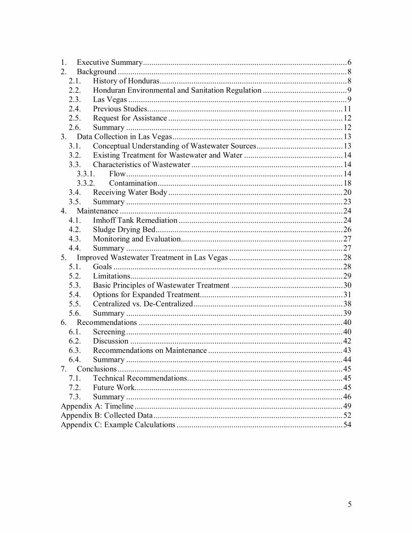
1. Executive Summary.................................................................................................6 2. Background .............................................................................................................8
2.1. History of Honduras.........................................................................................8 2.2. Honduran Environmental and Sanitation Regulation ........................................9 2.3. Las Vegas ........................................................................................................9 2.4. Previous Studies.............................................................................................11 2.5. Request for Assistance ...................................................................................12 2.6. Summary .......................................................................................................12
3. Data Collection in Las Vegas.................................................................................13 3.1. Conceptual Understanding of Wastewater Sources.........................................13 3.2. Existing Treatment for Wastewater and Water ...............................................14 3.3. Characteristics of Wastewater ........................................................................14
3.3.1. Flow.......................................................................................................14 3.3.2. Contamination........................................................................................18
3.4. Receiving Water Body ...................................................................................20 3.5. Summary .......................................................................................................23
4. Maintenance ..........................................................................................................24 4.1. Imhoff Tank Remediation ..............................................................................24 4.2. Sludge Drying Bed.........................................................................................26 4.3. Monitoring and Evaluation.............................................................................27 4.4. Summary .......................................................................................................27
5. Improved Wastewater Treatment in Las Vegas ......................................................28 5.1. Goals .............................................................................................................28 5.2. Limitations.....................................................................................................29 5.3. Basic Principles of Wastewater Treatment .....................................................30 5.4. Options for Expanded Treatment....................................................................31 5.5. Centralized vs. De-Centralized.......................................................................38 5.6. Summary .......................................................................................................39
6. Recommendations .................................................................................................40 6.1. Screening .......................................................................................................40 6.2. Discussion .....................................................................................................42 6.3. Recommendations on Maintenance ................................................................43 6.4. Summary .......................................................................................................44
7. Conclusions ...........................................................................................................45 7.1. Technical Recommendations..........................................................................45 7.2. Future Work...................................................................................................45 7.3. Summary .......................................................................................................46
Appendix A: Timeline ...................................................................................................49 Appendix B: Collected Data..........................................................................................52 Appendix C: Example Calculations ...............................................................................54
6
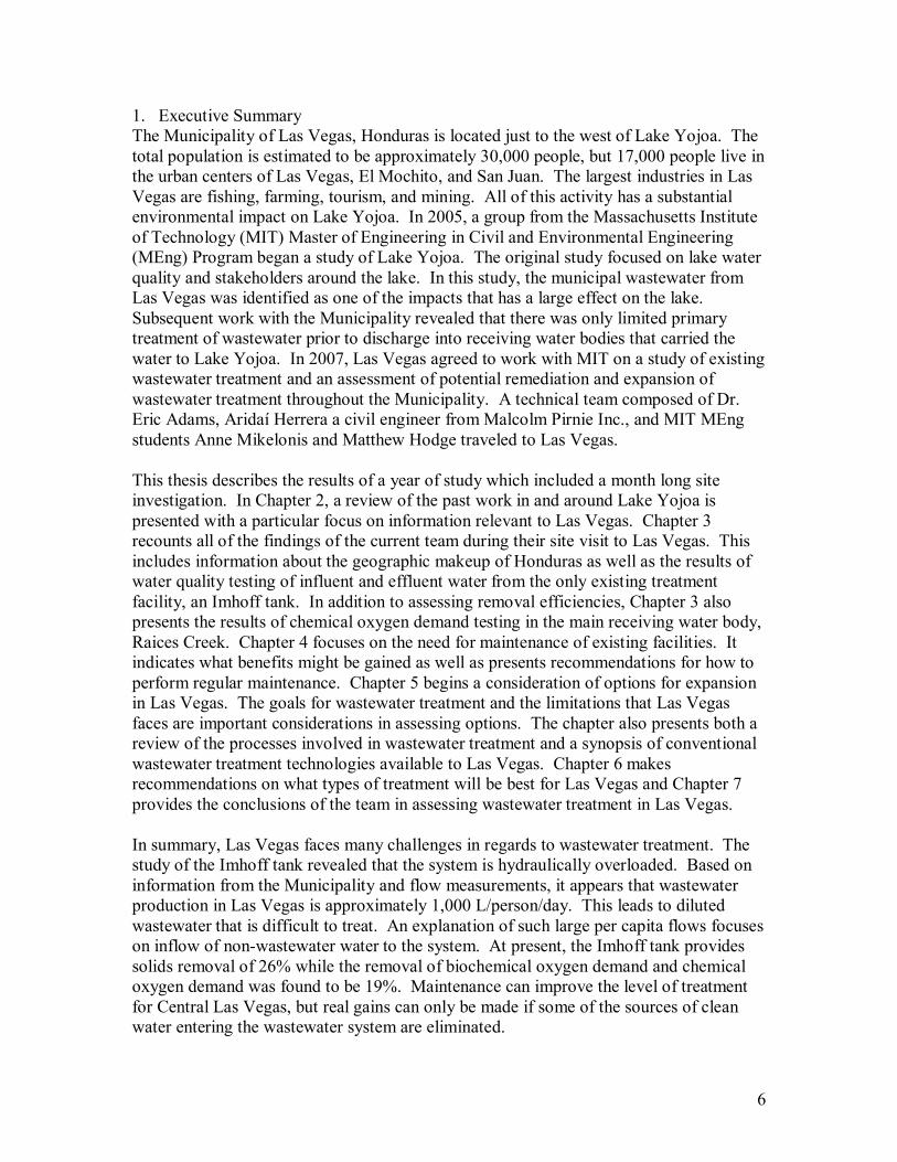
1. Executive Summary The Municipality of Las Vegas, Honduras is located just to the west of Lake Yojoa. The total population is estimated to be approximately 30,000 people, but 17,000 people live in the urban centers of Las Vegas, El Mochito, and San Juan. The largest industries in Las Vegas are fishing, farming, tourism, and mining. All of this activity has a substantial environmental impact on Lake Yojoa. In 2005, a group from the Massachusetts Institute of Technology (MIT) Master of Engineering in Civil and Environmental Engineering (MEng) Program began a study of Lake Yojoa. The original study focused on lake water quality and stakeholders around the lake. In this study, the municipal wastewater from Las Vegas was identified as one of the impacts that has a large effect on the lake. Subsequent work with the Municipality revealed that there was only limited primary treatment of wastewater prior to discharge into receiving water bodies that carried the water to Lake Yojoa. In 2007, Las Vegas agreed to work with MIT on a study of existing wastewater treatment and an assessment of potential remediation and expansion of wastewater treatment throughout the Municipality. A technical team composed of Dr. Eric Adams, Aridaí Herrera a civil engineer from Malcolm Pirnie Inc., and MIT MEng students Anne Mikelonis and Matthew Hodge traveled to Las Vegas. This thesis describes the results of a year of study which included a month long site investigation. In Chapter 2, a review of the past work in and around Lake Yojoa is presented with a particular focus on information relevant to Las Vegas. Chapter 3 recounts all of the findings of the current team during their site visit to Las Vegas. This includes information about the geographic makeup of Honduras as well as the results of water quality testing of influent and effluent water from the only existing treatment facility, an Imhoff tank. In addition to assessing removal efficiencies, Chapter 3 also presents the results of chemical oxygen demand testing in the main receiving water body, Raices Creek. Chapter 4 focuses on the need for maintenance of existing facilities. It indicates what benefits might be gained as well as presents recommendations for how to perform regular maintenance. Chapter 5 begins a consideration of options for expansion in Las Vegas. The goals for wastewater treatment and the limitations that Las Vegas faces are important considerations in assessing options. The chapter also presents both a review of the processes involved in wastewater treatment and a synopsis of conventional wastewater treatment technologies available to Las Vegas. Chapter 6 makes recommendations on what types of treatment will be best for Las Vegas and Chapter 7 provides the conclusions of the team in assessing wastewater treatment in Las Vegas. In summary, Las Vegas faces many challenges in regards to wastewater treatment. The study of the Imhoff tank revealed that the system is hydraulically overloaded. Based on information from the Municipality and flow measurements, it appears that wastewater production in Las Vegas is approximately 1,000 L/person/day. This leads to diluted wastewater that is difficult to treat. An explanation of such large per capita flows focuses on inflow of non-wastewater water to the system. At present, the Imhoff tank provides solids removal of 26% while the removal of biochemical oxygen demand and chemical oxygen demand was found to be 19%. Maintenance can improve the level of treatment for Central Las Vegas, but real gains can only be made if some of the sources of clean water entering the wastewater system are eliminated.
7
Based on the topography of Las Vegas, the available resources, and the difficulty posed by inflow to the sewage system, the best wastewater treatment system for Las Vegas is a decentralized system that takes advantage of the natural creeks to convey water downstream. The smaller treatment facilities that would make up this decentralized system should include some form of primary treatment to remove solids and possible some form of secondary treatment to remove pathogens. One example of an appropriately designed unit would be an Imhoff tank and maturation pond combination. In addition to these unit processes a sludge drying bed is necessary to allow the Municipality to maintain the facilities and remove sludge after it has been digested. In conclusion, Las Vegas can reduce its environmental impact on Lake Yojoa by beginning a culture of regular maintenance within the municipal staff and installing primary treatment throughout the Municipality.
8
2. Background Since 2005 MIT has been studying Lake Yojoa, the largest inland lake in Honduras, and the various stakeholders around the lake who contribute to the anthropogenic environmental impact on the lake. The chronology of the project can be found in Appendix A. The Municipality of Las Vegas is one of these stakeholders and in January 2008, Dr. Eric Adams, Aridaí Herrera, Anne Mikelonis, and Matthew Hodge traveled to Honduras to work with the Municipality on its wastewater treatment system. This thesis is the individual work of the author, Matthew Hodge. While in Las Vegas, Hodge worked closely with Mikelonis to study many aspects of wastewater treatment in Las Vegas. His work focused on characterizing existing conditions in Las Vegas and considering options for expansion of sewerage and treatment to other urban areas in the Municipality. The purpose of this work was two fold. Not only did this work provide information to Las Vegas, it also supported the work of Mikelonis who studied the efficacy of chemically enhanced primary treatment (CEPT) in the existing wastewater treatment facility (Mikelonis 2008). Hodge and Mikelonis quickly learned that there were many non-technical issues that effect wastewater treatment in Las Vegas and Honduras in general. For this reason, the thesis begins with a review recent history in Honduras and of the substantial information that has been collected in the previous work in and around Las Vegas.
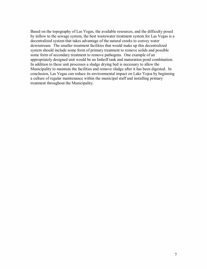
2.1. History of Honduras Located in Central America, Honduras is bordered on the southeast by Nicaragua, on the west by Guatemala, on the southwest by El Salvador, and on the north by the Atlantic Ocean, shown in Figure 1. The country�s capital is Tegucigalpa, but the industrial center is San Pedro Sula. Approximately two thirds of the way between these two cities is the Lago de Yojoa, or Lake Yojoa. The Municipality of Las Vegas is located approximately 5 kilometers to the west of Lake Yojoa.
Figure 1 Map of Honduras and Central America (Honduras 2007)
The country gained independence in 1821. Honduras is currently considered the second poorest country in Central America and one of the poorest countries in the Western Hemisphere (Honduras 2007). During the twentieth century the majority of economic
9
development was driven by foreign companies (Booth and Walker 1993) which built infrastructure and provided services to their employees. As a consequence of this situation, the concept of paying tariffs or taxes to local government in return for basic services (i.e. water and sanitation) is not a part of Honduran culture or society (Chavez 2008). Now efforts to improve water and sanitation services through local municipalities is a focus of a World Bank program known as the Strategic Plan for Modernization of the Water and Sanitation Sector (PEMAPS). The goal of this program is to develop a strategic plan for the modernization of water and sewerage services at the municipal level (Status of Projects in Execution-FY07 2007). The need for increased treatment in Honduras is substantial.
2.2. Honduran Environmental and Sanitation Regulation In 2004 it was estimated that approximately 68% of Honduran�s had access to adequate sanitation. Approximately 25% of the population had domestic connections (i.e. flush toilets) and the remaining 43% had latrines. Within urban areas it is estimated that 88% of the population had access to sanitary services (SERNA 2005). In an effort to change this situation, the government of Honduras established the Consejo Nacional de Agua Potable y Sanamiento (CONASA) in 2003. This advisory board is composed of existing government officials including: the Secretary of Health, the Secretary of Governance and Justice, the Secretary of Natural Resources and the Environment and other representatives (Sanamiento 2005a). Through CONASA national effluent quality standards were carried over from previous developments in 1997 (Sanamiento 2005b). Under the supervision of CONASA is the agency: Servicio Autonomo Nacional de Acueductos y Alcantarillados (SANAA) which is responsible for supporting both municipalities and local water boards in developing infrastructure to meet effluent water quality standards across the country (Sanamiento 2005c). While this regulatory structure is well designed a potential shortcoming arises in that the effluent water quality standards appear to be designed specifically for advanced secondary treatment. This level of treatment is not within the financial capabilities of many municipalities in Honduras. Most existing treatment is not capable of meeting these effluent standards, making enforcement quite difficult.
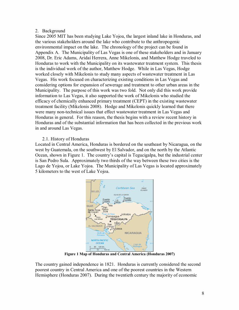
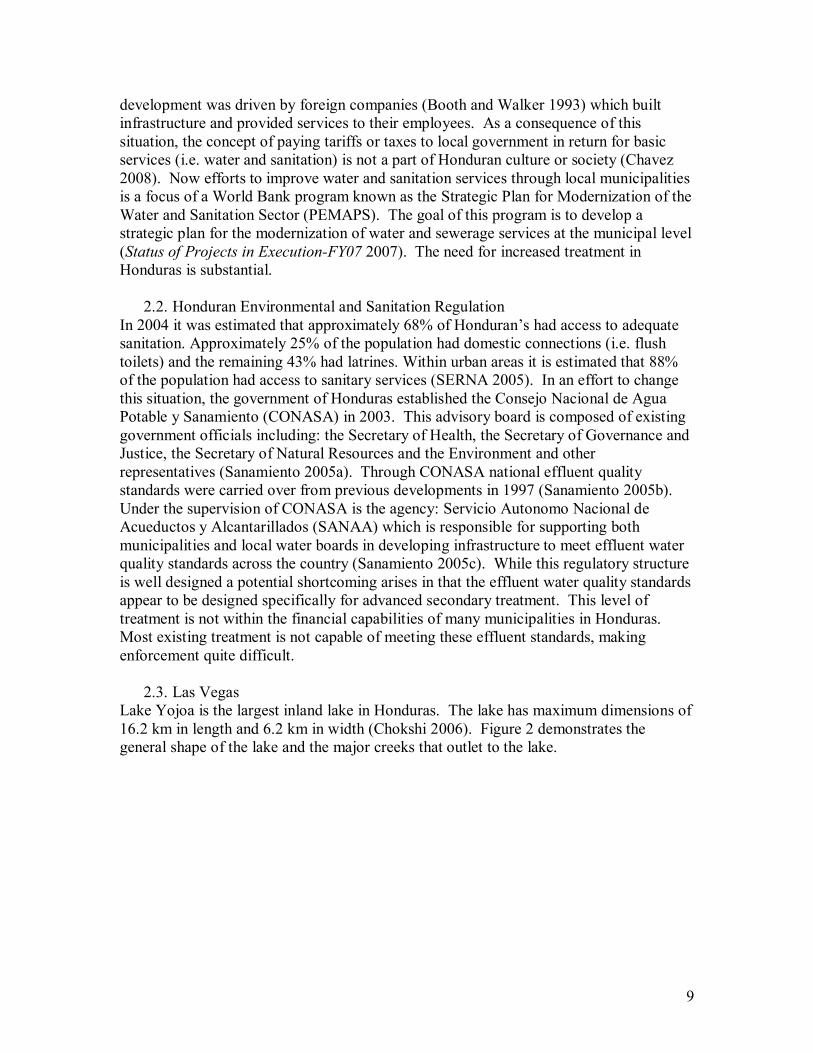
2.3. Las Vegas Lake Yojoa is the largest inland lake in Honduras. The lake has maximum dimensions of 16.2 km in length and 6.2 km in width (Chokshi 2006). Figure 2 demonstrates the general shape of the lake and the major creeks that outlet to the lake.
10
Figure 2 Map of Lake Yojoa (Trate 2006)
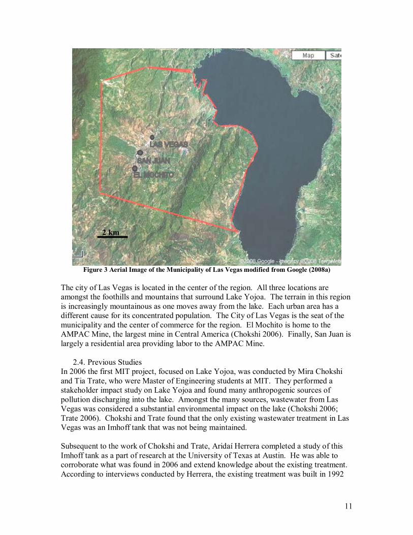
The Municipality of Las Vegas is located to the west of Lake Yojoa in the general area along the creek named �Quebrada de Raices� in Figure 2. The Municipality has a total population of 30,000 with approximately 17,000 people in towns or neighborhoods and the remainder living in rural areas throughout the Municipality. The major urban areas are: Las Vegas, El Mochito Mocho Arriba (El Mochito), and San Juan. Figure 3 outlines the approximate extents of the Municipality and the location of the urban areas.
Las Vegas
11
Figure 3 Aerial Image of the Municipality of Las Vegas modified from Google (2008a)
The city of Las Vegas is located in the center of the region. All three locations are amongst the foothills and mountains that surround Lake Yojoa. The terrain in this region is increasingly mountainous as one moves away from the lake. Each urban area has a different cause for its concentrated population. The City of Las Vegas is the seat of the municipality and the center of commerce for the region. El Mochito is home to the AMPAC Mine, the largest mine in Central America (Chokshi 2006). Finally, San Juan is largely a residential area providing labor to the AMPAC Mine.
2.4. Previous Studies In 2006 the first MIT project, focused on Lake Yojoa, was conducted by Mira Chokshi and Tia Trate, who were Master of Engineering students at MIT. They performed a stakeholder impact study on Lake Yojoa and found many anthropogenic sources of pollution discharging into the lake. Amongst the many sources, wastewater from Las Vegas was considered a substantial environmental impact on the lake (Chokshi 2006; Trate 2006). Chokshi and Trate found that the only existing wastewater treatment in Las Vegas was an Imhoff tank that was not being maintained. Subsequent to the work of Chokshi and Trate, Aridaí Herrera completed a study of this Imhoff tank as a part of research at the University of Texas at Austin. He was able to corroborate what was found in 2006 and extend knowledge about the existing treatment. According to interviews conducted by Herrera, the existing treatment was built in 1992
2 km

12
and had not been maintained since its construction (Herrera 2006). Because of this, the Imhoff tank (a single tank with two parallel chambers) of Las Vegas was not functioning properly. While as of 2003 the tank still provided ample suspended solids removal, it was no longer providing expected biochemical oxygen demand removal. Further evidence of ineffective primary treatment was an increase in fecal coliform concentrations in the effluent when compared to the influent (Experco 2003). Herrera described in detail many of the complications that may have arisen in the Las Vegas treatment system from the lack of maintenance and developed a set of recommendations regarding the remediation of the existing Imhoff tank in Las Vegas.
2.5. Request for Assistance As a part of Herrera�s work he developed strong working relationships with the Municipality of Las Vegas. In 2007, he recommended to Dr. Eric Adams that Las Vegas was ready to remediate the tank and that the Municipality was in need of additional technical assistance. Based on this recommendation, Dr. Adams began development of the current project with Herrera, Anne Mikelonis and Matthew Hodge. Six focus areas of study were identified prior to the site visit.
1) Removal efficiency of the existing tank 2) Downstream water quality analysis 3) Options for sludge handling 4) Identification of local sources of coagulants 5) Bench and/or pilot scale testing of chemically enhanced primary treatment (CEPT) 6) Conceptual design of a full scale system for CEPT application
Once on site, an additional request for assistance was specified by the Municipality: a conceptual design of a complete wastewater treatment system for all of the urban areas in the Municipality of Las Vegas.
2.6. Summary Las Vegas, Santa Barbara, Honduras is a growing municipality that discharges wastewater to a system of creeks that eventually outlet into Lake Yojoa. The Municipality has limited wastewater treatment. The Municipality wants to both improve the performance of existing facilities and expand sewerage and treatment to other areas of the Municipality. This thesis describes the analysis carried out by Matthew Hodge which focuses on: existing conditions at the existing treatment facility, downstream water quality analysis, options for sludge handling, and a conceptual design of wastewater treatment for the urban area of Las Vegas.
13
3. Data Collection in Las Vegas One of the major focuses of the site visit in January 2008 was the collection of information about wastewater treatment in Las Vegas. For the existing facility the questions that needed to be answered were: where does the wastewater come from, how much flow is there, and what are the concentrations of contaminants in the influent and effluent water? There are also questions that are relevant to system expansion: how many people require access to sewerage, is there any existing treatment in other areas, and if not what is currently done with human waste in these areas? The answers to these questions were found through discussions with the municipal staff, water quality testing and personal observation.
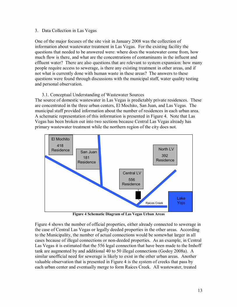
3.1. Conceptual Understanding of Wastewater Sources The source of domestic wastewater in Las Vegas is predictably private residences. These are concentrated in the three urban centers, El Mochito, San Juan, and Las Vegas. The municipal staff provided information about the number of residences in each urban area. A schematic representation of this information is presented in Figure 4. Note that Las Vegas has been broken out into two sections because Central Las Vegas already has primary wastewater treatment while the northern region of the city does not.
Figure 4 Schematic Diagram of Las Vegas Urban Areas
Figure 4 shows the number of official properties, either already connected to sewerage in the case of Central Las Vegas or legally deeded properties in the other areas. According to the Municipality, the number of actual connections would be somewhat larger in all cases because of illegal connections or non-deeded properties. As an example, in Central Las Vegas it is estimated that the 556 legal connection that have been made to the Imhoff tank are augmented by and additional 40 to 50 illegal connections (Godoy 2008a). A similar unofficial need for sewerage is likely to exist in the other urban areas. Another valuable observation that is presented in Figure 4 is the system of creeks that pass by each urban center and eventually merge to form Raices Creek. All wastewater, treated
El Mochito
418 Residence San Juan
181 Residence
North LV
392 Residence
Central LV
556 Residence
Lake YojoRaices Creek
14
and untreated, from the urban areas is currently discharged into these creeks and conveyed to Lake Yojoa.
3.2. Existing Treatment for Wastewater and Water Prior to entering the creeks, there are three levels of treatment that were found in the urban centers of the Municipality. Central Las Vegas has primary treatment with a single Imhoff tank. The design capacity of this facility is the wastewater production for 4,000 people, who produce on average 200 L/person/day (Ortiz 1991). The next level of treatment is partial primary treatment. El Mochito does not have a central treatment facility, but has had a system of septic tanks for quite some time. Few details were available about this system, but according to engineers with the AMPAC Mine, one of the companies that had previously owned the mine built a sewage system for its employees in El Mochito (Bautista 2008). A single septic tank receives wastewater from anywhere from 4 to 30 residences (Godoy 2008a). From visual inspection it was clear that most if not all of these tanks were in total disrepair and discharging wastewater directly into the nearest creek. Much like the Imhoff tank, these septic tanks are in need of regular maintenance. The third level of treatment in Las Vegas is non-treatment. Many residences discharge wastewater directly into the nearest creek without any form of treatment.
3.3. Characteristics of Wastewater The sources of wastewater are clear. The next question that needs to be addressed is how much is generated and what is the makeup of this wastewater. It was not possible to directly measure either of these things in all three urban areas, but a study of wastewater quantity and quality was conducted for the Imhoff tank that treats the wastewater of Central Las Vegas. The results of this study were assumed to apply to the other urban areas in Las Vegas.
3.3.1. Flow In his 2006 thesis, Herrera found and reported a study by Experco International, a Canadian engineering consulting firm. Experco conducted both water quality testing and continuous flow monitoring for a 24 hour cycle in April 2003. The results of that flow study are re-presented in Figure 5.

15
Figure 5 Diurnal Flow for Las Vegas Imhoff Tank (Herrera 2006)
16
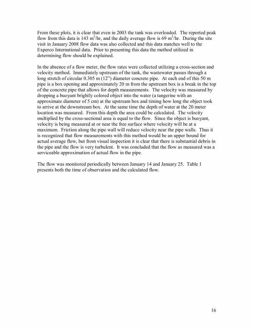
From these plots, it is clear that even in 2003 the tank was overloaded. The reported peak flow from this data is 143 m3/hr, and the daily average flow is 69 m3/hr. During the site visit in January 2008 flow data was also collected and this data matches well to the Experco International data. Prior to presenting this data the method utilized in determining flow should be explained. In the absence of a flow meter, the flow rates were collected utilizing a cross-section and velocity method. Immediately upstream of the tank, the wastewater passes through a long stretch of circular 0.305 m (12�) diameter concrete pipe. At each end of this 50 m pipe is a box opening and approximately 20 m from the upstream box is a break in the top of the concrete pipe that allows for depth measurements. The velocity was measured by dropping a buoyant brightly colored object into the water (a tangerine with an approximate diameter of 5 cm) at the upstream box and timing how long the object took to arrive at the downstream box. At the same time the depth of water at the 20 meter location was measured. From this depth the area could be calculated. The velocity multiplied by the cross-sectional area is equal to the flow. Since the object is buoyant, velocity is being measured at or near the free surface where velocity will be at a maximum. Friction along the pipe wall will reduce velocity near the pipe walls. Thus it is recognized that flow measurements with this method would be an upper bound for actual average flow, but from visual inspection it is clear that there is substantial debris in the pipe and the flow is very turbulent. It was concluded that the flow as measured was a serviceable approximation of actual flow in the pipe. The flow was monitored periodically between January 14 and January 25. Table 1 presents both the time of observation and the calculated flow.
17
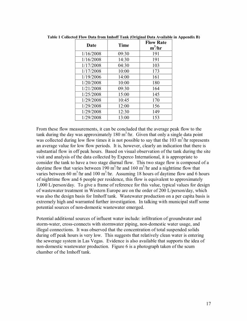
Table 1 Collected Flow Data from Imhoff Tank (Original Data Available in Appendix B)
Date Time Flow Rate m3/hr
1/16/2008 09:30 191 1/16/2008 14:30 191 1/17/2008 04:30 103 1/17/2008 10:00 173 1/19/2006 14:00 161 1/20/2008 10:00 180 1/21/2008 09:30 164 1/25/2008 15:00 145 1/29/2008 10:45 170 1/29/2008 12:00 156 1/29/2008 12:30 149 1/29/2008 13:00 153
From these flow measurements, it can be concluded that the average peak flow to the tank during the day was approximately 180 m3/hr. Given that only a single data point was collected during low flow times it is not possible to say that the 103 m3/hr represents an average value for low flow periods. It is, however, clearly an indication that there is substantial flow in off peak hours. Based on visual observation of the tank during the site visit and analysis of the data collected by Experco International, it is appropriate to consider the tank to have a two stage diurnal flow. This two stage flow is composed of a daytime flow that varies between 190 m3/hr and 160 m3/hr and a nighttime flow that varies between 60 m3/hr and 100 m3/hr. Assuming 18 hours of daytime flow and 6 hours of nighttime flow and 6 people per residence, this flow is equivalent to approximately 1,000 L/person/day. To give a frame of reference for this value, typical values for design of wastewater treatment in Western Europe are on the order of 200 L/person/day, which was also the design basis for Imhoff tank. Wastewater production on a per capita basis is extremely high and warranted further investigation. In talking with municipal staff some potential sources of non-domestic wastewater emerged. Potential additional sources of influent water include: infiltration of groundwater and storm-water, cross-connects with stormwater piping, non-domestic water usage, and illegal connections. It was observed that the concentration of total suspended solids during off peak hours is very low. This suggests that relatively clean water is entering the sewerage system in Las Vegas. Evidence is also available that supports the idea of non-domestic wastewater production. Figure 6 is a photograph taken of the scum chamber of the Imhoff tank.
18
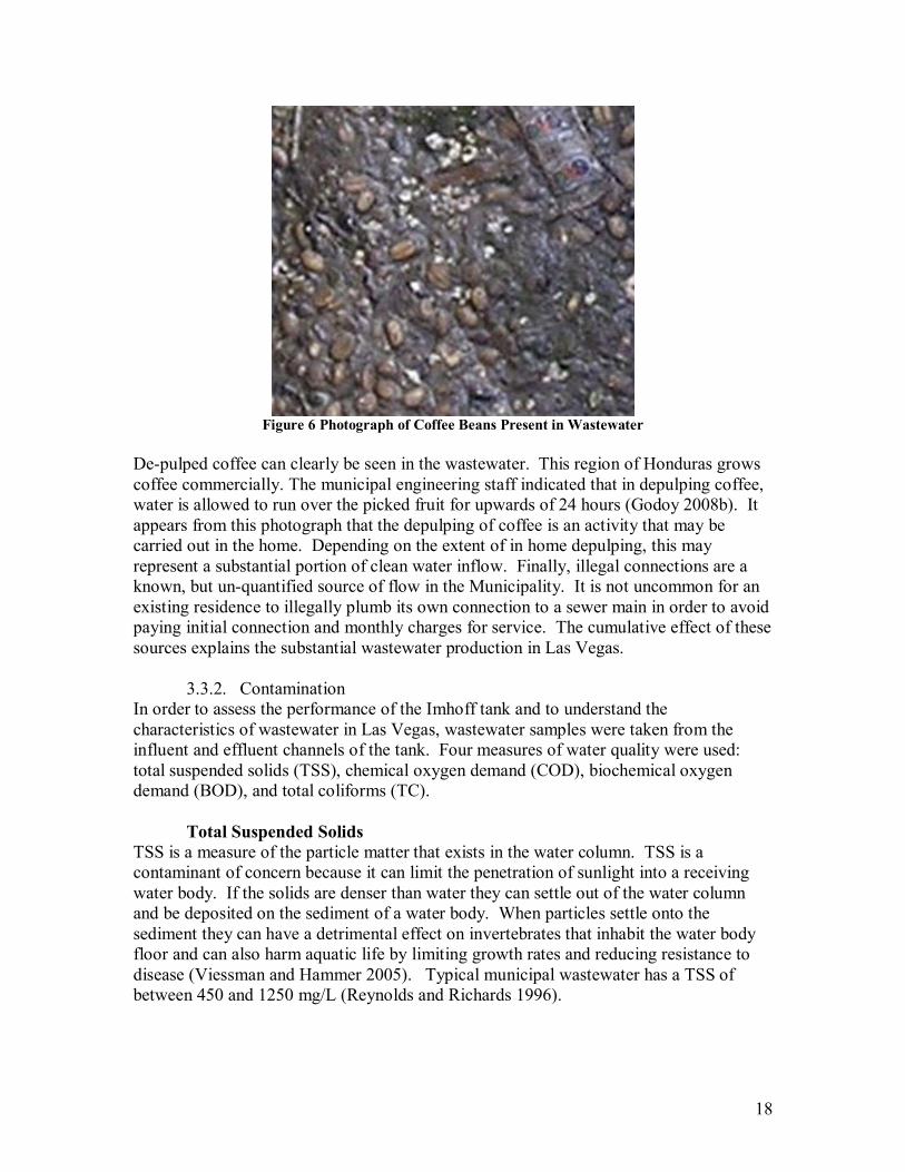
Figure 6 Photograph of Coffee Beans Present in Wastewater
De-pulped coffee can clearly be seen in the wastewater. This region of Honduras grows coffee commercially. The municipal engineering staff indicated that in depulping coffee, water is allowed to run over the picked fruit for upwards of 24 hours (Godoy 2008b). It appears from this photograph that the depulping of coffee is an activity that may be carried out in the home. Depending on the extent of in home depulping, this may represent a substantial portion of clean water inflow. Finally, illegal connections are a known, but un-quantified source of flow in the Municipality. It is not uncommon for an existing residence to illegally plumb its own connection to a sewer main in order to avoid paying initial connection and monthly charges for service. The cumulative effect of these sources explains the substantial wastewater production in Las Vegas.
3.3.2. Contamination In order to assess the performance of the Imhoff tank and to understand the characteristics of wastewater in Las Vegas, wastewater samples were taken from the influent and effluent channels of the tank. Four measures of water quality were used: total suspended solids (TSS), chemical oxygen demand (COD), biochemical oxygen demand (BOD), and total coliforms (TC).
Total Suspended Solids TSS is a measure of the particle matter that exists in the water column. TSS is a contaminant of concern because it can limit the penetration of sunlight into a receiving water body. If the solids are denser than water they can settle out of the water column and be deposited on the sediment of a water body. When particles settle onto the sediment they can have a detrimental effect on invertebrates that inhabit the water body floor and can also harm aquatic life by limiting growth rates and reducing resistance to disease (Viessman and Hammer 2005). Typical municipal wastewater has a TSS of between 450 and 1250 mg/L (Reynolds and Richards 1996).

19
TSS is measured by filtering a water sample under a partial vacuum. The filter is weighed prior to and after the filtering of the water sample. The difference in weight is the measure of total solids in the sample. This mass divided by the volume of the water sample yields the concentration of TSS. The methodology used in testing TSS is the �Total Suspended Solids Gravimetric Method Standard Method 2540.�
Chemical and Biochemical Oxygen Demand COD and BOD are in and of themselves not directly a pollutant of concern. However, the presence of dissolved oxygen (DO) is one of, if not the, most important water quality indicators. Typically, a DO concentration of 5 mg/L is necessary to maintain healthy aquatic life in water bodies (Viessman and Hammer 2005). As potential sinks of dissolved oxygen, BOD and COD become important water quality indicators as well. BOD is a measure of the oxygen used by microorganisms in order to biodegrade contaminants in receiving water bodies. COD on the other hand is �the oxygen equivalent of the organic matter susceptible to oxidation by a strong chemical oxidant� (Viessman and Hammer 2005). Typically, BOD is of greater interest for domestic wastewater, but BOD testing is timing consuming typically consisting of either a 5 day or 28 day measurement of water samples. COD can be correlated to BOD so a common practice is to take limited BOD readings and many COD readings and then estimate BOD from COD. That procedure was followed in this project. The method used to measure COD was the �HACH Chemical Oxygen Demand Colorimetric Method 8000� and for BOD the �Biochemical Oxygen Demand Method 5210� method was used.
Total Coliforms TC is not a wastewater contaminant in and of itself either. It is used as a surrogate for measuring the presence of microbes, viruses, and bacteria that can cause sickness in humans. Testing for individual pathogens requires many complicated testing procedures. In lieu of such intensive testing, TC has been adopted as a good indicator of the potential presence of pathogens. They originate in the intestinal tract of warm-blooded animals including humans. Therefore, if coliforms are present, it is reasonable that other fecal matter may be present. Non-human coliforms are indistinguishable from human coliforms so utilizing coliform counts to assess the risk of pathogens requires knowledge about contributing waters, sources and destinations. TC counts are typically performed by incubating a sample of water in a nutrient rich environment and then applying a dye to the background media that reacts with the coliforms to produce a different color. From there, the coliforms can be counted and this number divided by the volume of the water sample to determine the concentration of coliforms. The approved method for measuring coliforms is the �Membrane Filter Technique for Members of the Coliform Group Standard Method 9222.� Due to limitations of onsite laboratory equipment, a simplified testing method was utilized in place of the standard method. 3M E.Coli/Coliform Count Plates were used to measure TC in Las Vegas. This test is similar in principle to Standard Method 9222.

20
While for the most part, on site investigations went very smoothly, there were some complications that had a direct effect on the availability and accuracy of water quality data. The first complication was the lack of an analytical balance. While on site, the investigators were able to use an analytical balance at the laboratory of the Aqua Finca fish farm. However, this balance only had accuracy to 0.001 grams. Since the difference of pre and post weights of TSS samples were often less than 0.01 grams only two significant digits were recorded for these readings. A second complication arose when the 3M E. Coli/Coliform Plates were stolen from the Las Vegas laboratory facility. For this reason, TC counts are only available from early sampling. Table 2 presents the removal rates for the water quality characteristics that were monitored during the site visit. For all test data refer to Appendix B.
Table 2 Treatment Performance of Imhoff Tank Without Remediation Characteristic Influent Effluent Percent Change
TSS 190 mg/L 140 mg/L - 26% BOD 150 mg/L 120 mg/L - 19% COD 320 mg/L 260 mg/L - 19% TC 500 x 106 1800 x 106 + 260%
The results of the assessment of the performance of water quality for the influent and effluent flow to the Imhoff tank are comparable to the values that would be theoretically expected for an Imhoff tank that has such large flows to an undersized sedimentation tank (Reynolds and Richards 1996). The only abnormal result that was found was the substantial increase in TC passing out of the Imhoff tank. While sedimentation is not considered an effective method for coliform removal, it is an effective method for solids removal. It is expected that a large portion of bacteria, especially fecal coliforms would be attached to the fecal matter (solids). Therefore it is logical to expect at least some reduction in TC concentrations. A potential reason for this situation was found through visual inspection. It was observed that methane gas is released from the digestion chamber through the central sedimentation tank as well as the scum chambers. At times, this gas carries up to the surface large masses of partially digested solids. These solids, which would likely be very high in bacteria, do not immediately descend to the bottom of the chamber when the methane bubble breaks. Instead they float on the surface. When this occurs close to the outlet of the Imhoff tank they become part of the effluent water. This bubbling and solids re-suspension is a regular occurrence and may explain the increase in TC concentrations. Imhoff tanks are actually designed to prevent just this situation, so it is possible that the Imhoff tank in Las Vegas was not correctly built and remediation may be necessary.
3.4. Receiving Water Body Immediately downstream of the Imhoff tank is the Raices Creek. This receiving water body may be an important factor in assessing wastewater treatment options in Las Vegas because it is the way that most people in Las Vegas come in contact with the effluent

21
wastewater flow. It is also the way that all wastewater is conveyed to Lake Yojoa. Some study of the creek was possible, specifically measuring the COD in the creek. Figure 7 highlights the flow path of the Raices Creek to Lake Yojoa.
Figure 7 Flow Path of Raices Creek Modified from Google (2008b)
The creek takes on flows from creeks that pass by El Mochito, San Juan, and North Las Vegas. Currently this creek is not only accepting semi-treated effluent from the Imhoff tank, but also receiving untreated wastewater from each of these other areas. Locals who live near the creek have another name for Raices Creek that loosely translated means Feces Creek. The local community is aware of the poor water quality in the creek. All of the creeks that eventually join to form Raices Creek are steep and have relatively turbulent flow. Figure 8 is typical of the creeks.
1 km
22
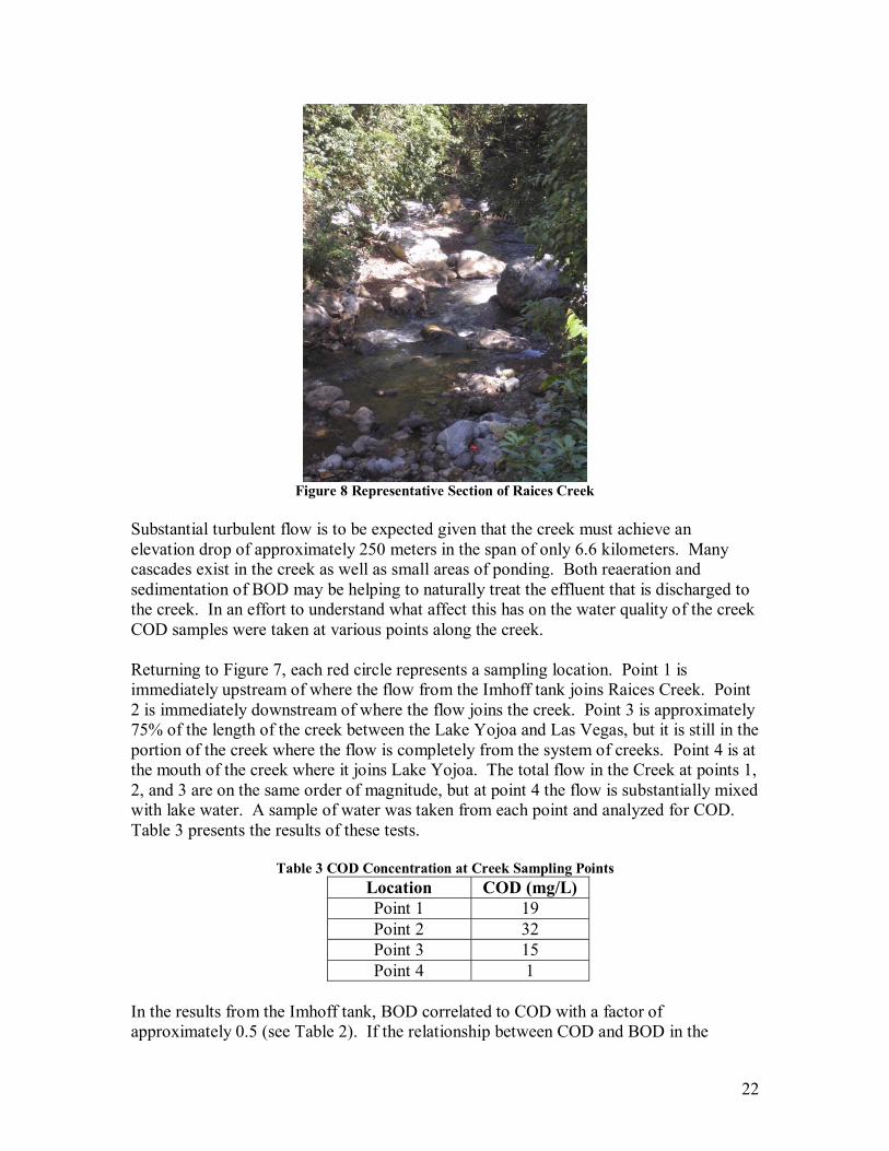
Figure 8 Representative Section of Raices Creek
Substantial turbulent flow is to be expected given that the creek must achieve an elevation drop of approximately 250 meters in the span of only 6.6 kilometers. Many cascades exist in the creek as well as small areas of ponding. Both reaeration and sedimentation of BOD may be helping to naturally treat the effluent that is discharged to the creek. In an effort to understand what affect this has on the water quality of the creek COD samples were taken at various points along the creek.
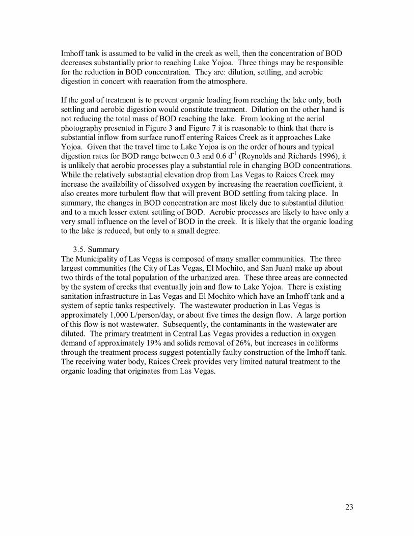
Returning to Figure 7, each red circle represents a sampling location. Point 1 is immediately upstream of where the flow from the Imhoff tank joins Raices Creek. Point 2 is immediately downstream of where the flow joins the creek. Point 3 is approximately 75% of the length of the creek between the Lake Yojoa and Las Vegas, but it is still in the portion of the creek where the flow is completely from the system of creeks. Point 4 is at the mouth of the creek where it joins Lake Yojoa. The total flow in the Creek at points 1, 2, and 3 are on the same order of magnitude, but at point 4 the flow is substantially mixed with lake water. A sample of water was taken from each point and analyzed for COD. Table 3 presents the results of these tests.
Table 3 COD Concentration at Creek Sampling Points Location COD (mg/L) Point 1 19 Point 2 32 Point 3 15 Point 4 1
In the results from the Imhoff tank, BOD correlated to COD with a factor of approximately 0.5 (see Table 2). If the relationship between COD and BOD in the
23
Imhoff tank is assumed to be valid in the creek as well, then the concentration of BOD decreases substantially prior to reaching Lake Yojoa. Three things may be responsible for the reduction in BOD concentration. They are: dilution, settling, and aerobic digestion in concert with reaeration from the atmosphere. If the goal of treatment is to prevent organic loading from reaching the lake only, both settling and aerobic digestion would constitute treatment. Dilution on the other hand is not reducing the total mass of BOD reaching the lake. From looking at the aerial photography presented in Figure 3 and Figure 7 it is reasonable to think that there is substantial inflow from surface runoff entering Raices Creek as it approaches Lake Yojoa. Given that the travel time to Lake Yojoa is on the order of hours and typical digestion rates for BOD range between 0.3 and 0.6 d-1 (Reynolds and Richards 1996), it is unlikely that aerobic processes play a substantial role in changing BOD concentrations. While the relatively substantial elevation drop from Las Vegas to Raices Creek may increase the availability of dissolved oxygen by increasing the reaeration coefficient, it also creates more turbulent flow that will prevent BOD settling from taking place. In summary, the changes in BOD concentration are most likely due to substantial dilution and to a much lesser extent settling of BOD. Aerobic processes are likely to have only a very small influence on the level of BOD in the creek. It is likely that the organic loading to the lake is reduced, but only to a small degree.
3.5. Summary The Municipality of Las Vegas is composed of many smaller communities. The three largest communities (the City of Las Vegas, El Mochito, and San Juan) make up about two thirds of the total population of the urbanized area. These three areas are connected by the system of creeks that eventually join and flow to Lake Yojoa. There is existing sanitation infrastructure in Las Vegas and El Mochito which have an Imhoff tank and a system of septic tanks respectively. The wastewater production in Las Vegas is approximately 1,000 L/person/day, or about five times the design flow. A large portion of this flow is not wastewater. Subsequently, the contaminants in the wastewater are diluted. The primary treatment in Central Las Vegas provides a reduction in oxygen demand of approximately 19% and solids removal of 26%, but increases in coliforms through the treatment process suggest potentially faulty construction of the Imhoff tank. The receiving water body, Raices Creek provides very limited natural treatment to the organic loading that originates from Las Vegas.
24
4. Maintenance Before Las Vegas builds new wastewater treatment facilities, there is an opportunity to improve the performance of existing facilities through maintenance. As has already been mentioned, prior to Herrera�s study, the Imhoff tank had not been properly maintained in over 15 years. In December 2007, the tank was emptied of sludge, but no other maintenance was performed. In addition to regular maintenance, a sludge drying bed is a necessary extension of the facility in Central Las Vegas so that digested sludge can be eliminated in an environmentally appropriate manner.
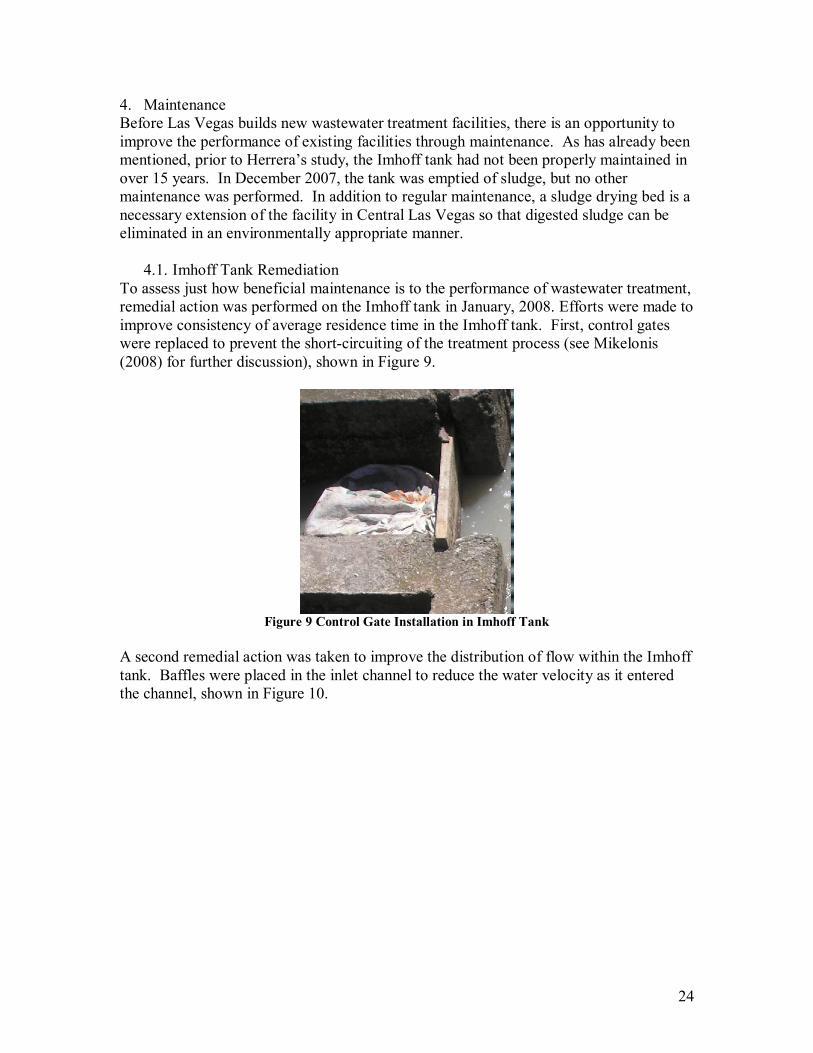
4.1. Imhoff Tank Remediation To assess just how beneficial maintenance is to the performance of wastewater treatment, remedial action was performed on the Imhoff tank in January, 2008. Efforts were made to improve consistency of average residence time in the Imhoff tank. First, control gates were replaced to prevent the short-circuiting of the treatment process (see Mikelonis (2008) for further discussion), shown in Figure 9.
Figure 9 Control Gate Installation in Imhoff Tank
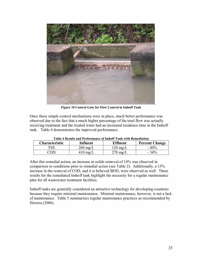
A second remedial action was taken to improve the distribution of flow within the Imhoff tank. Baffles were placed in the inlet channel to reduce the water velocity as it entered the channel, shown in Figure 10.
25
. Figure 10 Control Gate for Flow Control in Imhoff Tank
Once these simple control mechanisms were in place, much better performance was observed due to the fact that a much higher percentage of the total flow was actually receiving treatment and the treated water had an increased residence time in the Imhoff tank. Table 4 demonstrates the improved performance.
Table 4 Results and Performance of Imhoff Tank with Remediation Characteristic Influent Effluent Percent Change
TSS 200 mg/L 120 mg/L - 40% COD 410 mg/L 270 mg/L - 34%
After this remedial action, an increase in solids removal of 14% was observed in comparison to conditions prior to remedial action (see Table 2). Additionally, a 15% increase in the removal of COD, and it is believed BOD, were observed as well. These results for the remediated Imhoff tank highlight the necessity for a regular maintenance plan for all wastewater treatment facilities. Imhoff tanks are generally considered an attractive technology for developing countries because they require minimal maintenance. Minimal maintenance, however, is not a lack of maintenance. Table 5 summarizes regular maintenance practices as recommended by Herrera (2006).
26
Table 5 Recommended Maintenance Schedule for Imhoff Tank Period Actions Daily Remove refuse from the influent channel, examine gates and
baffles to ensure proper flow distribution, examine effluent piping and remove any obstructions
Semiweekly Remove scum from scum chamber and place in sludge drying bedMonthly Reverse flow direction to distribute sludge evenly in digestion
chamber Semiannually Remove approximately 40 m3 of sludge from digestion chamber
and place in sludge drying bed This table is not the sum total of necessary knowledge to maintain an Imhoff tank, but it is a set of rules that will lead to better tank performance. Should these guidelines be followed, a new problem will arise regarding maintenance. Digested sludge must be disposed of in some manner. During maintenance in January 2008, the sludge was discharged directly into the creek. This is not an acceptable practice. The simplest forms of sludge disposal are incineration, land application, or burial. Prior to any of these processes, the liquid sludge must be dried to a solid material. Therefore the construction of a sludge drying bed is perhaps the most important step towards regular maintenance that the Municipality can take.
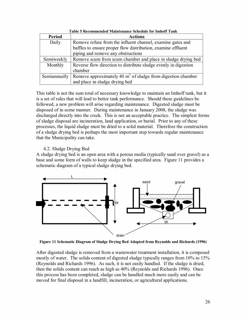
4.2. Sludge Drying Bed A sludge drying bed is an open area with a porous media (typically sand over gravel) as a base and some form of walls to keep sludge in the specified area. Figure 11 provides a schematic diagram of a typical sludge drying bed.
Figure 11 Schematic Diagram of Sludge Drying Bed Adapted from Reynolds and Richards (1996)
After digested sludge is removed from a wastewater treatment installation, it is composed mostly of water. The solids content of digested sludge typically ranges from 10% to 15% (Reynolds and Richards 1996). As such, it is not easily handled. If the sludge is dried, then the solids content can reach as high as 40% (Reynolds and Richards 1996). Once this process has been completed, sludge can be handled much more easily and can be moved for final disposal in a landfill, incineration, or agricultural applications.
L
W
W
sand gravel
drain

27
A sludge drying bed achieves the removal of water by both drainage of water through the porous media and by evaporation of water to the atmosphere. The required maintenance is minimal and typical sizing is usually in the range of 6 m � 9 m by 8 m � 38 m, for an individual bed. In the case where more drying area is needed, multiple beds can be built side by side. In dryer environments appropriate drying typically occurs in 2 to 4 weeks (Reynolds and Richards 1996). In the case of Las Vegas it will be important to include a roof or other cover structure to prevent rain from diluting and rewetting the sludge in the drying bed. Sludge removal and processing is a critical step in any wastewater treatment system that generates sludge. It is necessary in both a centralized system design and a decentralized system design. For detailed calculations of appropriately sized sludge drying beds for Las Vegas, see Appendix C.
4.3. Monitoring and Evaluation If the municipal staff begins to perform regular maintenance and potentially expands the wastewater treatment system in Las Vegas, regular monitoring will also become important. Ideally this would include solids loading and organic loading to each treatment facility. This type of testing can be expensive and complicated, but at the very least the Municipality can easily begin to monitor the total flow to each of their facilities. A simple way to improve monitoring would be to place a V-Notch weir in the influent channel for each treatment facility. By monitoring the depth of flow over the weir, the total flow can be accurately calculated with accepted equations. The relationship between flow and water depth will depend on the angle of the notch, but once in place and calibrated, measurements of flow will be substantially easier than the tangerine method utilized in the current investigation. The placing of a V-notch weir in the existing Imhoff tank may prove to be impossible since the influent channel did not have much freeboard during January, the dry season. During the rainy season, an obstruction in the channel like a weir may cause wastewater to overflow the channel before it reaches the Imhoff tank. A detailed investigation of a weir will be required before a recommendation can be as to the viability of a weir for the existing treatment facility.
4.4. Summary Las Vegas is interested in expanding wastewater treatment in the Municipality. Prior to expanding treatment, the Municipality must focus on establishing regular maintenance for existing wastewater treatment. The recommendations made by Herrera are appropriate for maintaining the existing Imhoff tank. Additionally, the Municipality has a need for a sludge disposal system. Central to this is a sludge drying bed so that the sludge can be dried sufficiently to be disposed of with conventional means.
28
5. Improved Wastewater Treatment in Las Vegas The Municipality of Las Vegas is committed to reducing the impact that it has on Lake Yojoa. It was clear in meeting with the Mayor, Carlos Fuentes, and other stakeholders around the lake that there is a perception that Las Vegas is one of the major polluters of Lake Yojoa. In addition to having a perception as a polluter, the Municipality is also engaged in an extensive program of development which includes expansion of electricity services, expansion of paved roads, and expansion of sewerage. As of December 2007 the Municipality had already secured funding from the government of Taiwan to expand and improve wastewater collection in the Municipality. Whether motivated by public perception or by development goals, the Municipality has committed to expanding sewerage and wastewater treatment. The question becomes, what will be the best system for Las Vegas? This depends on the level of treatment that the Municipality wants to achieve and what limitations it faces for new projects. After determining the goals and limitations for the situation in Las Vegas, it is possible to consider the technology options available to Las Vegas, but prior to that, it is instructive to review the basic principles that are relevant to wastewater treatment.
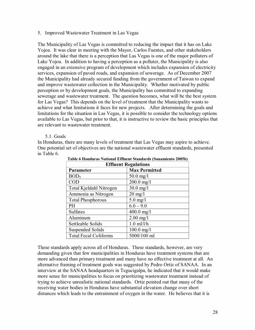
5.1. Goals In Honduras, there are many levels of treatment that Las Vegas may aspire to achieve. One potential set of objectives are the national wastewater effluent standards, presented in Table 6.
Table 6 Honduras National Effluent Standards (Sanamiento 2005b) Effluent Regulations
Parameter Max Permitted BOD5 50.0 mg/l COD 200.0 mg/l Total Kjeldahl Nitrogen 30.0 mg/l Ammonia as Nitrogen 20 mg/l Total Phosphorous 5.0 mg/l PH 6.0 � 9.0 Sulfates 400.0 mg/l Aluminum 2.00 mg/l Settleable Solids 1.0 ml/l/h Suspended Solids 100.0 mg/l Total Fecal Coliforms 5000/100 ml
These standards apply across all of Honduras. These standards, however, are very demanding given that few municipalities in Honduras have treatment systems that are more advanced than primary treatment and many have no effective treatment at all. An alternative framing of treatment goals was suggested by Pedro Ortiz of SANAA. In an interview at the SANAA headquarters in Tegucigalpa, he indicated that it would make more sense for municipalities to focus on prioritizing wastewater treatment instead of trying to achieve unrealistic national standards. Ortiz pointed out that many of the receiving water bodies in Honduras have substantial elevation change over short distances which leads to the entrainment of oxygen in the water. He believes that it is
29
better to focus on solids removal in primary treatment and particularly focus on methods to remove pathogens from effluent water in secondary treatment (Ortiz 2008). While the recommendation to focus on solids removal and pathogen removal are well reasoned and apply generally to wastewater treatment across Honduras, a third approach that Las Vegas can pursue is to prioritize its own wastewater treatment needs. In Las Vegas, at present, there is only limited exposure to wastewater. Once wastewater enters the system of creeks that conveys the water to Lake Yojoa, there is only one community that comes into regular contact with the contaminated water. Immediately downhill of the Imhoff tank that treats wastewater from Central Las Vegas, there is a community of approximately 25 families that cross through Raices Creek every day as they walk the road between their residences and Central Las Vegas. Other than that, no measurable portion of the population comes into contact with the stream until it reaches Lake Yojoa. The lake can act like an enormous detention pond where natural die off rates of microorganisms will eliminate nearly all pathogens. It may in fact make sense for Las Vegas to focus exclusively on the removal of solids from wastewater.
5.2. Limitations In addition to the goals for treatment, the available resources of Las Vegas will play a role in determining the best wastewater treatment options for Las Vegas. Las Vegas has substantial financial resources from multiple sources, including: the AMPAC Mine, the government of Taiwan, and the United States Agency for International Development. This is an advantage not typical of all municipalities in Honduras, but Las Vegas does face limitations regarding land, technical expertise, and political processes. Las Vegas is a large area, but it is also in the center of Honduras which is a mountainous region. There is very little flat land available for large infrastructure projects. Similarly, there is very little clear land. Any undeveloped land is covered by thick vegetation and trees. Any large scale infrastructure project would require an enormous amount of earthwork. The one exception to this is the area that was cleared during the construction of the Imhoff tank. This area is largely a flat open area, but, as has already been mentioned, immediately downhill approximately 25 families have begun living in the area. Any development in the area will see substantial public opposition. In addition to limited availability of land, Las Vegas is constrained by available technical expertise. The Municipality has one civil engineer on staff and he is responsible for everything from wastewater treatment, to road construction, to maintenance of government buildings. The technical capability of the Municipality does not include the kind of expertise necessary to operate modern wastewater treatment facilities like what is found commonly in the United States. An added problem with any modern system is the availability of materials. There are hardware stores in Las Vegas, but anything that must be imported can take months to arrive in Las Vegas. Politics play a role in everything in Honduras, including public services like wastewater collection and treatment. The entire staff of a municipality is changed when a new mayor is elected. This is especially true when the new mayor is from a different political party

30
than the previous mayor. The complete changeover of staff calls into question whether any of the improvements that are made during the current mayor�s term of office will be maintained. Las Vegas is limited by project horizons. Long term planning is nearly impossible in this political situation. Any wastewater treatment design should take into account all of these factors.
5.3. Basic Principles of Wastewater Treatment The treatment of wastewater has two stages. The first stage is the removal of contaminants from water and the second stage is the final elimination of these contaminants. There are three types of processes that can be used to achieve both removal and elimination of contaminants. These processes are: physical, chemical, and biological. Physical processes are used principally in the removal stage of wastewater treatment while biological and chemical processes are used in both the removal and the elimination stage of the treatment. Most treatment systems will incorporate more than one process to effectively reduce the environmental impact of wastewater. A description of each process is supplied here to enhance understanding of the actual technology options available in designing a wastewater treatment system. The dominant physical process used in wastewater treatment is sedimentation. Sedimentation takes advantage of the fact that much of contamination in wastewater is in a solid form. If these solid particles are denser than water they will tend to sink and settle out of the water column. According to Stoke�s Law (Tchobanoglous et al. 2003), the velocity at which a particle will settle out of the water column can be calculated with Equation 1.
µρρ )(
92 2
Fps
grv
−= (1)
where: vs = settling velocity
r = radius of the particle g = constant of gravity ρP,F = density of the particle or fluid µ = dynamic fluid viscosity This process of settling can be utilized to remove �settleable� contaminants by forcing wastewater into a tank whose dimensions are such that particles will fall to the bottom of the tank before they exit the tank. By calculating the vertical settling velocity and the horizontal flow velocity of the water, it is possible to size a tank to remove a large portion of contaminant particles from wastewater. The key parameter in the sedimentation of solids from wastewater is hydraulic residence time (equation 2)
31
.
QV=τ (2)
where: Q = flow to sedimentation tank V = volume of sedimentation tank τ = residence time
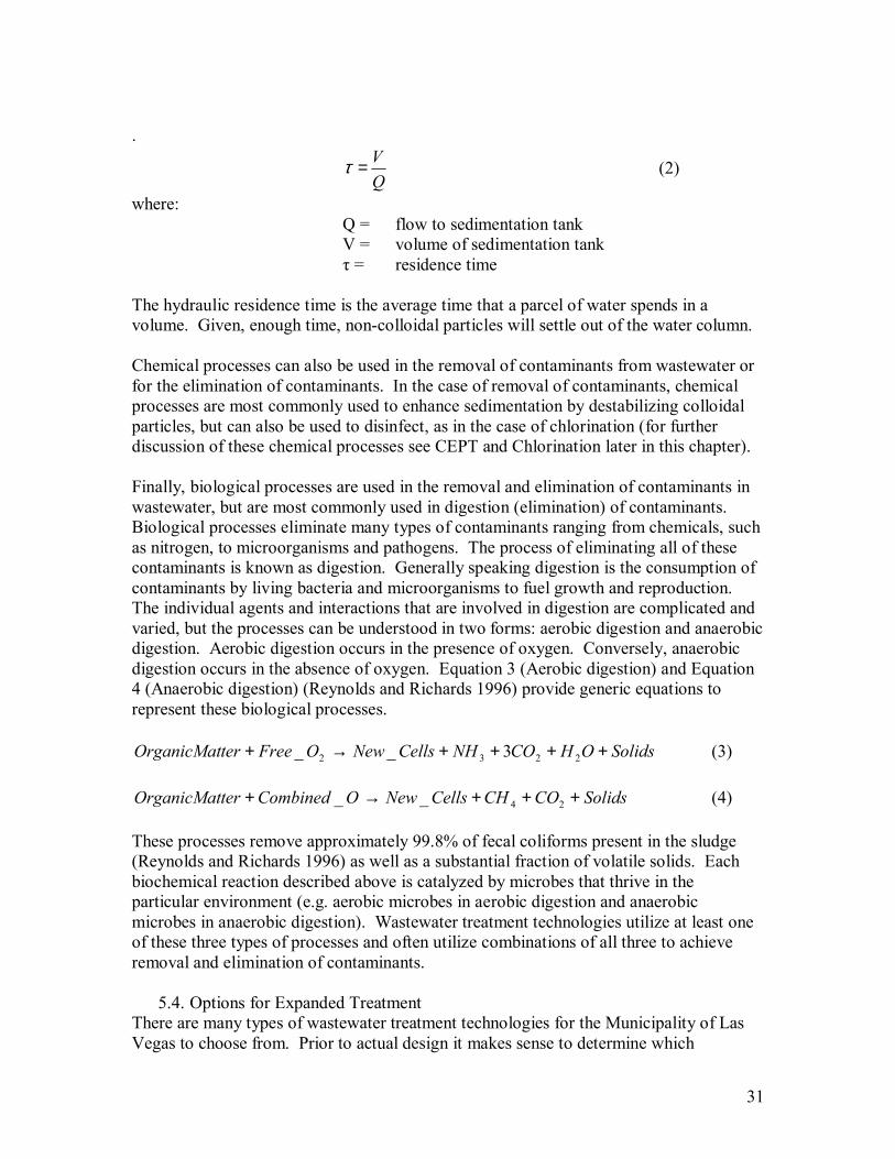
The hydraulic residence time is the average time that a parcel of water spends in a volume. Given, enough time, non-colloidal particles will settle out of the water column. Chemical processes can also be used in the removal of contaminants from wastewater or for the elimination of contaminants. In the case of removal of contaminants, chemical processes are most commonly used to enhance sedimentation by destabilizing colloidal particles, but can also be used to disinfect, as in the case of chlorination (for further discussion of these chemical processes see CEPT and Chlorination later in this chapter). Finally, biological processes are used in the removal and elimination of contaminants in wastewater, but are most commonly used in digestion (elimination) of contaminants. Biological processes eliminate many types of contaminants ranging from chemicals, such as nitrogen, to microorganisms and pathogens. The process of eliminating all of these contaminants is known as digestion. Generally speaking digestion is the consumption of contaminants by living bacteria and microorganisms to fuel growth and reproduction. The individual agents and interactions that are involved in digestion are complicated and varied, but the processes can be understood in two forms: aerobic digestion and anaerobic digestion. Aerobic digestion occurs in the presence of oxygen. Conversely, anaerobic digestion occurs in the absence of oxygen. Equation 3 (Aerobic digestion) and Equation 4 (Anaerobic digestion) (Reynolds and Richards 1996) provide generic equations to represent these biological processes.
SolidsOHCONHCellsNewOFreeterOrganicMat ++++→+ 2232 3__ (3)
SolidsCOCHCellsNewOCombinedterOrganicMat +++→+ 24__ (4) These processes remove approximately 99.8% of fecal coliforms present in the sludge (Reynolds and Richards 1996) as well as a substantial fraction of volatile solids. Each biochemical reaction described above is catalyzed by microbes that thrive in the particular environment (e.g. aerobic microbes in aerobic digestion and anaerobic microbes in anaerobic digestion). Wastewater treatment technologies utilize at least one of these three types of processes and often utilize combinations of all three to achieve removal and elimination of contaminants.
5.4. Options for Expanded Treatment There are many types of wastewater treatment technologies for the Municipality of Las Vegas to choose from. Prior to actual design it makes sense to determine which
32
technologies can be screened out by the goals and limitations of Las Vegas. A brief description of many types of conventional wastewater treatment is presented here to provide a basic understanding of the range of options available to Las Vegas.
Sedimentation Tank
A sedimentation tank is a simple form of wastewater treatment that is always paired with a form of treatment to eliminate contaminants. Sedimentation tanks can take on many forms, but the basic function of a sedimentation tank is to provide a laminar flow environment to allow gravity to cause solids in the water to settle out of the water column and be deposited on the bottom of the tank. Hydraulic residence time is the key parameter in sizing sedimentation tanks. It is necessary for a parcel of water to spend enough time in the tank to allow settleable solids to be removed from the water column.
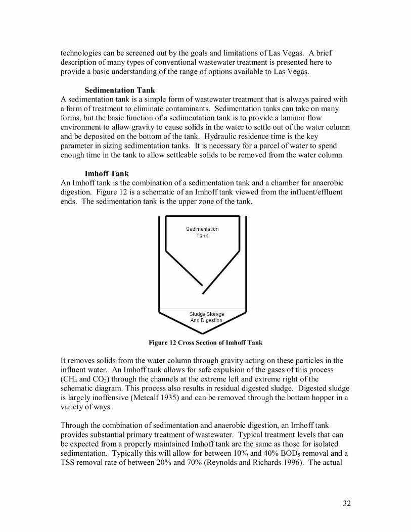
Imhoff Tank An Imhoff tank is the combination of a sedimentation tank and a chamber for anaerobic digestion. Figure 12 is a schematic of an Imhoff tank viewed from the influent/effluent ends. The sedimentation tank is the upper zone of the tank.
Figure 12 Cross Section of Imhoff Tank
It removes solids from the water column through gravity acting on these particles in the influent water. An Imhoff tank allows for safe expulsion of the gases of this process (CH4 and CO2) through the channels at the extreme left and extreme right of the schematic diagram. This process also results in residual digested sludge. Digested sludge is largely inoffensive (Metcalf 1935) and can be removed through the bottom hopper in a variety of ways. Through the combination of sedimentation and anaerobic digestion, an Imhoff tank provides substantial primary treatment of wastewater. Typical treatment levels that can be expected from a properly maintained Imhoff tank are the same as those for isolated sedimentation. Typically this will allow for between 10% and 40% BOD5 removal and a TSS removal rate of between 20% and 70% (Reynolds and Richards 1996). The actual
33
removal rate for a specific tank will be a function of influent water quality and tank residence time.
Septic Tank A septic tank is a low maintenance, high reliability, treatment method. A septic tank is identical in removal method to the upper chamber of an Imhoff tank. A watertight container is used to retain wastewater for approximately 24 hours. For a single household this typically requires a volume of 1.9 m3 to 5.7 m3 (Reynolds and Richards 1996). Once an appropriate residence time is achieved, gravity allows the settling of solids out of the water column and the buoyancy of fats and oils brings them to the surface in the tank. Depending on the relationship between flow rate and volume, a septic tank should also achieve TSS removals on the order of 20%-70% and BOD removals of 10%-40% (Reynolds and Richards 1996). Once the solids have settled to the bottom of the tank they begin to undergo anaerobic digestion (again as in an Imhoff tank). The retained water serves to prevent odor from being a nuisance in the area surrounding the tank. However, without a second compartment for this process there is a greater likelihood of scouring from the digesting sludge as compared to an Imoff tank. In addition to the risk of reintroducing sludge into the effluent, as the tank fills with sludge, the volume available for water decreases. Therefore, the residence time is reduced and the level of treatment drops.
Waste Stabilization Pond Waste stabilization ponds (WSPs) or oxidation ponds are a series of shallow open surface ponds that are fed by influent flows of wastewater. This technology is an increasingly popular form of wastewater treatment in Honduras (Chavez 2008). A 2000 publication by Oakley catalogued and explained many successful implementations of WSPs in Central America (Oakley et al. 2000). The results of this article were expanded and translated into a manual for the design, construction and maintenance of WSPs by USAID and FHIS. A typical installation of a WSP will consist of an anaerobic pond and/or a facultative pond followed by a maturation pond. The system is built in series, but each unit is usually built with a parallel unit to allow for maintenance while still treating influent wastewater. An anaerobic pond removes BOD through sedimentation of organic solids in the wastewater. Anaerobic conditions are maintained by preventing aerobic bacteria such as algae from growing in the pond. According to Mara (2004), a properly designed anaerobic pond can achieve BOD removal of up to 60%. The sludge that is generated is digested anaerobically, just as was described for an Imhoff tank. Typical design parameters for an anaerobic pond are depths of 2-5 meters and an organic loading rate of greater than 100 g BOD/m3-d (Mara 2004), high enough to prevent the presence of dissolved oxygen in the water column, yet still maintain a residence time of approximately 1 day.
34
While an anaerobic pond is often optional for a WSP system, facultative ponds are rarely omitted. A facultative pond also treats BOD, but this time it treats organic loading with aerobic processes. If a facultative pond is used as primary treatment, it will remove some BOD through sedimentation of solids; however, the main treatment mechanism is oxidation. Oxygen is provided to the water column through the prodigious growth of algae on the pond surface. Because the process is aerobic, loading to a facultative pond must be substantially less than an anaerobic pond. Typical design for a facultative pond includes a depth of 1.5 meters and a loading rate of 10-40 g BOD/m2 (Mara 2004) With this reduced flow an appropriate residence time is approximately 4 days. Regardless of primary treatment, any WSP system will have a maturation pond for the removal of pathogens. The removal of viral pathogens through physical processes is not completely understood, but it is generally believed that sedimentation is again responsible for die-off rates for pathogens (Mara 2004). Similarly, for bacterial removal, not all processes are completely understood, but sedimentation and consumption by other bacteria and micro invertebrates contribute as well as increased bacterial die-off rates from elevated temperatures. In consideration of these various mechanisms, the key parameter for design remains residence time. A typical maturation pond has a maximum depth of 1 m to maintain both high levels of light intensity and reduce variations in dissolved oxygen through the depth of the pond. Given that a maturation pond is typically relatively well mixed, a residence time of 4.9 days will achieve a one log, or 90%, removal of pathogens (for details of this calculation see Appendix C).
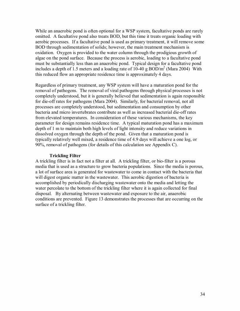
Trickling Filter A trickling filter is in fact not a filter at all. A trickling filter, or bio-filter is a porous media that is used as a structure to grow bacteria populations. Since the media is porous, a lot of surface area is generated for wastewater to come in contact with the bacteria that will digest organic matter in the wastewater. This aerobic digestion of bacteria is accomplished by periodically discharging wastewater onto the media and letting the water percolate to the bottom of the trickling filter where it is again collected for final disposal. By alternating between wastewater and exposure to the air, anaerobic conditions are prevented. Figure 13 demonstrates the processes that are occurring on the surface of a trickling filter.
35
Figure 13 Organic Digestion in Trickling Filters (Reynolds and Richards 1996)
Trickling filters cannot provide primary treatment, but when they are properly maintained they do provide adequate secondary treatment. Low rate filters are typically loaded with a hydraulic rate of 1.8 L/min-m2 and an organic loading rate of 0.2 kg BOD/m3-d (Reynolds and Richards 1996). In operation a trickling filter it is important to prevent the development of anaerobic conditions and to periodically flush the system so that as bacterial growth sloughs off of the media it does not clog pore space in the trickling filter. Another important consideration is the inclusion of methods to deal with the presence of flies which have been found to be nuisance in most low rate trickling filters (Reynolds and Richards 1996).
Upflow Anaerobic Sludge Blanket
Upflow anaerobic sludge blanket (UASB) systems provide primary treatment for the removal of solids through settling processes as well as digestion of solids through anaerobic processes. UASBs are concrete structures that allow influent wastewater to enter through the bottom of a tank. Either through hydraulic head or by pumping, water is forced upwards through a sludge layer (the blanket) allowing for contact between wastewater and anaerobic bacteria. As water passes upwards out of the blanket, the flow rate is maintained at a low rate so any solids that have passed through the blanket or organic material that may have come free from the blanket will again settle towards the bottom of the tank. Effluent channels are sloped upwards to promote this settling process. The recommended residence time for wastewater in a UASB is between 6 hours and 12 hours. Typical maximum capacities of UASBs are 4,000 m3 per day, and for a properly
medium
microbial growth
fixed water layer
moving water layer
oxygen and organic sorption
carbon dioxide release
36
maintained system BOD removal rates are on the order of 70% (Mara 2004). Dimensions of an UASB are limited by a typical maximum volume of 1,000 m3 and are usually rectangular with a length to width ratio of less than 4:1. In designing an UASB, some of the important considerations are the ability to regulate flow and access to the digestion zone. Because flow is in the opposite direction of settling particles, a delicate balance between the upward advective force of the water and the settling force of gravity must be controlled. If flow is inconsistent or too high, the settling of particles will be stopped and an UASB will stop providing treatment. Just as flow must be actively controlled, sludge removal must be frequently managed as well. According to Mara (2004), sludge removal must occur as frequently as every 2 weeks. The byproducts of digestion are released to the atmosphere through a venting system that prevents gas bubbles from passing up through the sludge blanket and disrupting the bacterial growth.
Aeration Aeration is the use of mechanical means to increase the presence of oxygen when organic matter in wastewater comes in contact with bacteria that will digest the material. This process is typically achieved by pumping oxygen in gas form into the bottom of a tank and letting that air rise through the water column. Oxygen will diffuse from the gas phase to the dissolved phase while the bubbles are in contact with water that is depleted of oxygen. Aeration can also be achieved by providing substantial mixing in the water column. In this form of aeration, the atmosphere acts as the source of oxygen and mixing helps to increase the rate at which this oxygen will diffuse into the water by constantly circulating the water and allowing water particles at all depths to come in contact with the surface. This process can be used in open air lagoons or ditches, but is most commonly used in activated sludge treatment processes.
Activated Sludge Activated sludge is the most common form of treatment for urban areas in the developed world. The process requires a fluidized bed of microorganisms that are capable of digesting the organic material in wastewater in an aerobic environment. In this advanced process, influent wastewater is mixed with activated sludge prior to entering a reactor. Activated sludge is sludge that has been recycled from the effluent of the reactor. Prior to being joined with influent wastewater it passes through some form of aeration to reintroduce high levels of oxygen into the sludge. This is what makes it activated. Once in the reactor, solids from the influent wastewater quickly sorb to the activated sludge. Digestion occurs rapidly as well as rapid cell production. This means that the net gain in growth must be removed from the reactor and from the recycling stream to maintain a stable reactor environment. The operation of an activated sludge system is complicated and involves expertise in microbiology, chemistry, and physics. Without writing a full text book it is difficult to give a comprehensive understanding of an activated sludge treatment facility. While such facilities do tend to be complicated, they also provide high levels of treatment, achieving BOD removal rates of as high as 95% (Reynolds and Richards 1996).
37
Latrine
A latrine or pit latrine is the most basic form of wastewater treatment. It is simply an open hole or pit in the ground that collects domestic waste. The waste is then left to decompose. Ventilated improved pit latrines provide ventilation to the storage chamber to increase oxygen and provide a sink of gases that may cause odor problems (Ujang and Henze 2006). This form of aerobic digestion of waste is slow and is typically only used for a single residence. A latrine can be built for a single use and then filled with soil, or parallel containment tanks can be built and used in an alternating pattern to allow for full digestion and removal of waste from one while the other is in use. Latrines are a basic, but effective way to reduce the amount of contact between human waste, a health hazard, and humans.
Chemically Enhanced Primary Treatment Chemically enhanced primary treatment (CEPT) is the use of coagulants such as aluminum sulfate (alum) and polymers to improve the removal of colloidal particles through sedimentation. In water, alum reacts with the natural alkalinity of the water to form aluminum hydroxide flocs. The electrolytic charge of the flocs overcomes the repulsive nature of colloidal particles forcing them to come into contact and form larger particles which will then settle through sedimentation. Polymers are added to provide a structure for the destabilized particles to attach to. The larger particles have higher settling velocities and will settle out of the water column. Obviously, CEPT can only be used in conjunction with regular settling and the necessary amount of chemicals will depend heavily on the characteristics of wastewater being treated. The use of CEPT leads to an increase in the generation of sludge in sedimentation. If the right conditions exist, it can increase settling rates substantially. Increases in the removal of both TSS and BOD have been observed in past testing (Mikelonis 2008).
Constructed Wetlands Constructed wetlands depend on sedimentation and ecological metabolism to treat domestic wastewater. These are the same processes that are active in WSPs. A constructed wetland is typically a partially controlled natural environment of either free water surface or submerged media that creates an environment where treatment mechanisms can function. The EPA identifies constructed wetlands as a treatment method that can receive primary effluent and will treat water to secondary standards (EPA 2000). Given this limitation, any installation of a constructed wetland must be in coordination with a form of primary treatment. The EPA (2000) reports average values for constructed wetlands in the United States to be: 80% removal for BOD5, 99% removal for total coliforms, and 82% removal for TSS. Hydraulic residence time is once again the critical design parameter and just like a WSP, constructed wetlands can be designed for a specific water quality characteristic based on necessary residence times. Some other typical design guidelines are an average wetland
38
depth of 1 m and a maximum organic loading rate of between 4.5 and 6.0 g BOD/m2*day (EPA 2000). In addition to general design characteristics for wastewater treatment, there are a number of other complicated design decisions that are a part of designing and implementing a constructed wetland. Part of efficient operation is maintaining the overall health of both plant and animal life in the constructed wetlands. Considerations range from pond bottom sloping to species variation and compatibility. In addition, an understanding of invasive species in the area is necessary. Even with these requirements, the main treatment process in a wetland is residence time. Therefore, it can be sized with methods similar to those used for WSPs and will require comparable size. In addition to the requirements of ample land, it will also require more maintenance.
Chlorination Chlorination is one of the most common forms of disinfection. It is a practice in many water and wastewater applications in the United States. When chlorine is added to water hydrogen and chlorine ions disassociate, shown in Equation 5 (Viessman and Hammer 2005).
−+ ++⇔+ ClHHOClOHCl 22 (5) These ions will attach and corrode any material they come in contact with including cell walls of microorganisms. In this way they will kill microorganisms in wastewater. Determining the appropriate dose of chlorine to disinfect wastewater, but not harm aquatic life in the receiving water body, is a difficult process and requires a full understanding of water quality characteristics especially pH. Depending on the constituents of wastewater, it is possible to generate both chlorophenols and trihalomethanes. Some technical expertise is required to accurately determine appropriate levels of chlorination. In addition to technical needs, dosing chlorine in wastewater can be a substantial cost. The bulk cost of chlorine can be the limiting factor in the potential use of chlorine for wastewater disinfection. As should now be clear, there are many types of technology available to Las Vegas for wastewater treatment. The calculus of selection is not limited to technical considerations. In the next chapter a screening process is used to select preferred technologies given the limitations and goals of Las Vegas.
5.5. Centralized vs. De-Centralized As well as selecting specific technologies, Las Vegas has a more general decision to make. The Municipality can either have a centralized system for treating all of the wastewater in a single location and piping to transport wastewater to this location or it can have a decentralized system with smaller treatment facilities near each urban area. A centralized system for Las Vegas would have to be located at an elevation that is lower than all of the urban areas so that it can be a gravity driven system. This leaves only the area immediately downhill of the existing Imhoff tank. A decentralized system of wastewater treatment would provide a local treatment facility for each urban area. This
39
system can then take advantage of the existing system of creeks to convey the effluent wastewater. The disadvantage of a decentralized system is that it requires the use of space in each urban area. It would also mean more locations within the Municipality that would be exposed to the harms and risks of wastewater treatment.
5.6. Summary There are many options in wastewater treatment technologies. The right system for a specific installation depends on the goals for treatment and the limiting local conditions. For the Municipality of Las Vegas, the ideal wastewater treatment system is low maintenance, resilient, and requires very little land for installation. The next chapter will determine which combination of technologies meets this requirement.
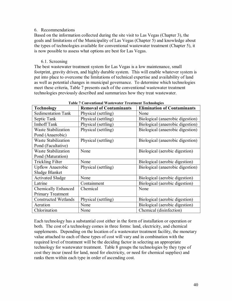
40
6. Recommendations Based on the information collected during the site visit to Las Vegas (Chapter 3), the goals and limitations of the Municipality of Las Vegas (Chapter 5) and knowledge about the types of technologies available for conventional wastewater treatment (Chapter 5), it is now possible to assess what options are best for Las Vegas.
6.1. Screening The best wastewater treatment system for Las Vegas is a low maintenance, small footprint, gravity driven, and highly durable system. This will enable whatever system is put into place to overcome the limitations of technical expertise and availability of land as well as potential changes in municipal governance. To determine which technologies meet these criteria, Table 7 presents each of the conventional wastewater treatment technologies previously described and summarizes how they treat wastewater.
Table 7 Conventional Wastewater Treatment Technologies Technology Removal of Contaminants Elimination of Contaminants Sedimentation Tank Physical (settling) None Septic Tank Physical (settling) Biological (anaerobic digestion) Imhoff Tank Physical (settling) Biological (anaerobic digestion) Waste Stabilization Pond (Anaerobic)
Physical (settling) Biological (anaerobic digestion)
Waste Stabilization Pond (Facultative)
Physical (settling) Biological (anaerobic digestion)
Waste Stabilization Pond (Maturation)
None Biological (aerobic digestion)
Trickling Filter None Biological (aerobic digestion) Upflow Anaerobic Sludge Blanket
Physical (settling) Biological (anaerobic digestion)
Activated Sludge None Biological (aerobic digestion) Latrine Containment Biological (aerobic digestion) Chemically Enhanced Primary Treatment
Chemical None
Constructed Wetlands Physical (settling) Biological (aerobic digestion) Aeration None Biological (aerobic digestion) Chlorination None Chemical (disinfection) Each technology has a substantial cost either in the form of installation or operation or both. The cost of a technology comes in three forms: land, electricity, and chemical supplements. Depending on the location of a wastewater treatment facility, the monetary value attached to each of these types of cost will vary and in combination with the required level of treatment will be the deciding factor in selecting an appropriate technology for wastewater treatment. Table 8 groups the technologies by they type of cost they incur (need for land, need for electricity, or need for chemical supplies) and ranks them within each type in order of ascending cost.
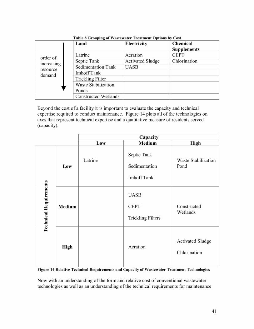
41
Table 8 Grouping of Wastewater Treatment Options by Cost Land Electricity Chemical
Supplements Latrine Aeration CEPT Septic Tank Activated Sludge Chlorination Sedimentation Tank UASB Imhoff Tank Trickling Filter Waste Stabilization Ponds
Constructed Wetlands Beyond the cost of a facility it is important to evaluate the capacity and technical expertise required to conduct maintenance. Figure 14 plots all of the technologies on axes that represent technical expertise and a qualitative measure of residents served (capacity). Capacity Low Medium High
Low
Latrine
Septic Tank Sedimentation Imhoff Tank
Waste Stabilization Pond
Medium
UASB CEPT Trickling Filters
Constructed Wetlands
Tec
hnic
al R
equi
rem
ents
High
Aeration
Activated Sludge Chlorination
Figure 14 Relative Technical Requirements and Capacity of Wastewater Treatment Technologies Now with an understanding of the form and relative cost of conventional wastewater technologies as well as an understanding of the technical requirements for maintenance
order of increasing resource demand
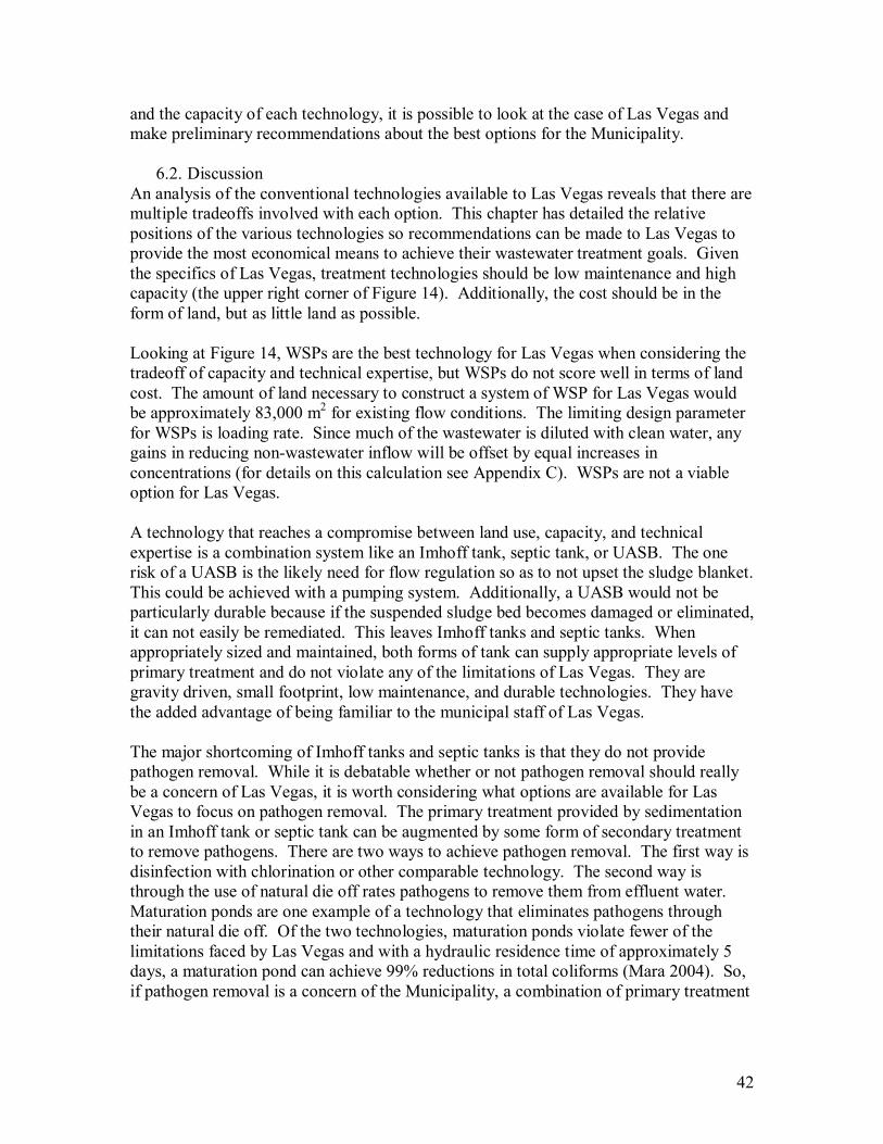
42
and the capacity of each technology, it is possible to look at the case of Las Vegas and make preliminary recommendations about the best options for the Municipality.
6.2. Discussion An analysis of the conventional technologies available to Las Vegas reveals that there are multiple tradeoffs involved with each option. This chapter has detailed the relative positions of the various technologies so recommendations can be made to Las Vegas to provide the most economical means to achieve their wastewater treatment goals. Given the specifics of Las Vegas, treatment technologies should be low maintenance and high capacity (the upper right corner of Figure 14). Additionally, the cost should be in the form of land, but as little land as possible. Looking at Figure 14, WSPs are the best technology for Las Vegas when considering the tradeoff of capacity and technical expertise, but WSPs do not score well in terms of land cost. The amount of land necessary to construct a system of WSP for Las Vegas would be approximately 83,000 m2 for existing flow conditions. The limiting design parameter for WSPs is loading rate. Since much of the wastewater is diluted with clean water, any gains in reducing non-wastewater inflow will be offset by equal increases in concentrations (for details on this calculation see Appendix C). WSPs are not a viable option for Las Vegas. A technology that reaches a compromise between land use, capacity, and technical expertise is a combination system like an Imhoff tank, septic tank, or UASB. The one risk of a UASB is the likely need for flow regulation so as to not upset the sludge blanket. This could be achieved with a pumping system. Additionally, a UASB would not be particularly durable because if the suspended sludge bed becomes damaged or eliminated, it can not easily be remediated. This leaves Imhoff tanks and septic tanks. When appropriately sized and maintained, both forms of tank can supply appropriate levels of primary treatment and do not violate any of the limitations of Las Vegas. They are gravity driven, small footprint, low maintenance, and durable technologies. They have the added advantage of being familiar to the municipal staff of Las Vegas. The major shortcoming of Imhoff tanks and septic tanks is that they do not provide pathogen removal. While it is debatable whether or not pathogen removal should really be a concern of Las Vegas, it is worth considering what options are available for Las Vegas to focus on pathogen removal. The primary treatment provided by sedimentation in an Imhoff tank or septic tank can be augmented by some form of secondary treatment to remove pathogens. There are two ways to achieve pathogen removal. The first way is disinfection with chlorination or other comparable technology. The second way is through the use of natural die off rates pathogens to remove them from effluent water. Maturation ponds are one example of a technology that eliminates pathogens through their natural die off. Of the two technologies, maturation ponds violate fewer of the limitations faced by Las Vegas and with a hydraulic residence time of approximately 5 days, a maturation pond can achieve 99% reductions in total coliforms (Mara 2004). So, if pathogen removal is a concern of the Municipality, a combination of primary treatment
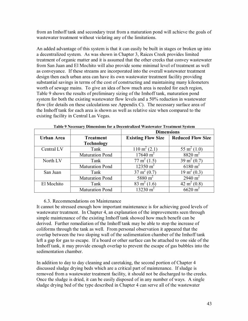
43
from an Imhoff tank and secondary treat from a maturation pond will achieve the goals of wastewater treatment without violating any of the limitations. An added advantage of this system is that it can easily be built in stages or broken up into a decentralized system. As was shown in Chapter 3, Raices Creek provides limited treatment of organic matter and it is assumed that the other creeks that convey wastewater from San Juan and El Mochito will also provide some minimal level of treatment as well as conveyance. If these streams are incorporated into the overall wastewater treatment design then each urban area can have its own wastewater treatment facility providing substantial savings in terms of the cost of constructing and maintaining many kilometers worth of sewage mains. To give an idea of how much area is needed for each region, Table 9 shows the results of preliminary sizing of the Imhoff tank, maturation pond system for both the existing wastewater flow levels and a 50% reduction in wastewater flow (for details on these calculations see Appendix C). The necessary surface area of the Imhoff tank for each area is shown as well as relative size when compared to the existing facility in Central Las Vegas.
Table 9 Necessary Dimensions for a Decentralized Wastewater Treatment System Dimensions
Urban Area Treatment Technology
Existing Flow Size Reduced Flow Size
Tank 110 m2 (2.1) 55 m2 (1.0) Central LV Maturation Pond 17640 m2 8820 m2
Tank 77 m2 (1.5) 39 m2 (0.7) North LV Maturation Pond 12350 m2 6180 m2
Tank 37 m2 (0.7) 19 m2 (0.3) San Juan Maturation Pond 5880 m2 2940 m2
Tank 83 m2 (1.6) 42 m2 (0.8) El Mochito Maturation Pond 13230 m2 6620 m2
6.3. Recommendations on Maintenance
It cannot be stressed enough how important maintenance is for achieving good levels of wastewater treatment. In Chapter 4, an explanation of the improvements seen through simple maintenance of the existing Imhoff tank showed how much benefit can be derived. Further remediation of the Imhoff tank may be able to stop the increase of coliforms through the tank as well. From personal observation it appeared that the overlap between the two sloping wall of the sedimentation chamber of the Imhoff tank left a gap for gas to escape. If a board or other surface can be attached to one side of the Imhoff tank, it may provide enough overlap to prevent the escape of gas bubbles into the sedimentation chamber. In addition to day to day cleaning and caretaking, the second portion of Chapter 4 discussed sludge drying beds which are a critical part of maintenance. If sludge is removed from a wastewater treatment facility, it should not be discharged to the creeks. Once the sludge is dried, it can be easily disposed of in any number of ways. A single sludge drying bed of the type described in Chapter 4 can serve all of the wastewater
44
treatment facilities that may be built throughout Las Vegas. If the Municipality can acquire a small tank to transport the wet sludge then the drying periods can be rotated for a single sludge drying bed.
6.4. Summary The Municipality of Las Vegas has multiple options to treat wastewater. These options range from latrines to waste stabilization ponds to activated sludge systems. Given the specific situation of Las Vegas, treatment technologies that have a small footprint are preferable. This leads to the conclusion that septic tanks and Imhoff tanks will provide more economical treatment for the Municipality. To improve pathogen removal, these primary systems can be coupled with secondary treatment in the form of maturation ponds. Finally, central to any expansion should be the inclusion of sludge drying bed for dewatering of sludge produced in wastewater treatment.
45
7. Conclusions The Municipality of Las Vegas, in Santa Barbara, Honduras has substantial political will to reduce the environmental impact that the Municipality has on Lake Yojoa. One of the major environmental impacts that Las Vegas has on the lake is domestic wastewater. Three urban areas represent approximately 60% of the 30,000 people who live in the Municipality. The wastewater from El Mochito, San Juan and North Las Vegas is discharged directly into a system of creeks that eventually outlet into Lake Yojoa. The only existing wastewater treatment in Las Vegas is an Imhoff tank in Central Las Vegas. The Imhoff tank is overloaded which results in theoretical hydraulic residence times of approximately 30 minutes. Direct observation indicates that the actual residence time is substantially less. Treatment levels are accordingly reduced. Total suspended solids, chemical oxygen demand, and biochemical oxygen demand is currently being removed at approximately 20%. At the same time total coliforms are increasing by 260%. This is most likely because of scouring from the digestion chamber of the Imhoff tank. Maintenance improved total suspended solids and chemical oxygen demand to almost 40%. It is speculated that a similar reduction in biochemical oxygen demand results from maintenance as well. The limiting factor in improving existing wastewater treatment is the amount of wastewater flow. Based on flow measurements and municipal records, typical wastewater production for Central Las Vegas is approximately 1,000 L/person/day. It is speculated that there are sources of wastewater that are not accounted for by the Municipality. Infiltration, illegal connections, open faucets, and non-domestic water use in the home all contribute to the excessive flow to the Imhoff tank. This extra flow dilutes wastewater. Wastewater is further diluted when it enters Raices Creek.
7.1. Technical Recommendations Las Vegas should determine what level of treatment it wants to provide to its wastewater prior to discharge of effluent to receiving water bodies. Based on the goals of protecting the environment and human health, a reasonable goal is to focus on primary treatment of all effluent with a secondary goal of focusing on the removal of pathogens from wastewater. Given the limitations of Las Vegas an appropriate technology for achieving this goal would be one that is gravity driven, low maintenance, small, and durable. After reviewing the breadth of conventional wastewater treatment technologies, the best option for Las Vegas is a set of Imhoff tanks or septic tanks. If additional pathogen removal is desired the sedimentation and digestion tanks can be followed by maturation ponds. There are multiple benefits to such a system of wastewater treatment. First, the municipal staff is already familiar with the technology. Second, this system can be implemented in stages and increased incrementally as needed. Finally, the technologies can be built in a single centralized location or in a decentralized way with each urban area having its own local treatment facility.
7.2. Future Work
46
Future work in Las Vegas has many potential avenues. Assuming that wastewater treatment is expanded in the Municipality there will be many opportunities for future engineering groups to monitor the performance of these systems. Perhaps the most interesting area of future work would be to investigate methods, technical and economic, that can help to reduce water consumption in the area. One first step would be to determine a method to monitor flows in the existing Imhoff tank. The effectiveness of wastewater treatment and implementation of water treatment will be completely controlled by the flow rates. To make any form of treatment economically attractive, water must be treated as a resource and not wasted. In areas like Las Vegas, water is readily available and scarcity is not a motivation to conservation. Therefore, other methods must be utilized to reduce consumption and make economies of scale in wastewater and water treatment realistic. In addition to treatment work, AMPAC Mine mentioned an interest in working with future groups to explore environmental concerns related to the mine. The work of Chokshi and Trate made it clear that there was a need and in some places an interest in environmental engineering services for all of the stakeholders around Lake Yojoa.
7.3. Summary The Municipality of Las Vegas, Santa Barbara, in Honduras can expand sewerage and wastewater treatment. Based on the results of an analysis of the existing wastewater treatment, a number of changes are necessary to produce effective treatment. The Municipality must make regular maintenance of treatment facilities a priority. In addition to maintaining treatment facilities, the Municipality must explore ways to reduce the amount of wastewater generated in the residences of the Municipality. Finally, system wide expansion will be most effective if it takes advantage of the natural conveyance and treatment available through a system of creeks that connect all of the urban areas. This means that a decentralized wastewater treatment system will be the most effective treatment in both economic and technical terms.

47
Bibliography
Bautista, M. 2008. Personal Communication with Bautista, M., AMPAC Engineer:
During Presentation and Discussion to AMPAC Mine. El Mochito, February 1 2008.
Booth, J. A. and T. W. Walker. 1993. Understanding Central America. 2nd ed. Boulder: Westview Press.
Chavez, H. 2008. Personal Communication with Chavez, H., FHIS Engineer: Wastewater Treatment in Honduras. Tegucigalpa, January 12, 2008.
Chokshi, M. 2006. Temperature analysis for lake Yojoa, Honduras. Thesis M. Eng. --Massachusetts Institute of Technology Dept. of Civil and Environmental Engineering 2006. Massachusetts Institute of Technology. Dept. of Civil and Environmental Engineering.
EPA, U. 2000. Manual: Constructed Wetlands Treatment of Muncipal Wastewaters, edited by N. R. M. R. L. Environmental Protection Agency, Office of Research and Development: US Environmental Protection Agency.
Experco, I. L. a. D. B. 2003. �Estudio de Factibilidad Para la Gestión Integrada de Las Aguas Residuales y Desechos Sólidos en La Cuenca del Lago de Yojoa - AMUPROLAGO�. Honduras, C.A.
Godoy, M. 2008a. Personal Communication with Godoy, M., Municipal Engineering Staff: El Mochito Site Visit. Las Vegas, January 12 2008.
Godoy, M. 2008b. Personal Communication with Godoy, M., Municipal Engineering Staff: Coffee Depulping, Domestic Connections. Las Vegas, January 21 2008.
Google. 2008a. Google Maps. http://maps.google.com/. Accessed February 29 2008. Google. 2008b. Google Maps. http://maps.google.com/. Accessed March 14 2008. Herrera, A. 2006. Rehabilitation of the Imhoff Tank Treatment Plant in Las Vegas, Santa
Bárbara Honduras, Central Américathesis, University of Texas, Austin. Honduras. 2007. https://www.cia.gov/library/publications/the-world-
factbook/geos/ho.html. Accessed February 15 2008. Mara, D. D. 2004. Domestic wastewater treatment in developing countries. London ;
Sterling, VA: Earthscan Publications. Metcalf, L. 1935. American sewerage practice. 3rd ed. New York,: McGraw-Hill. Mikelonis, A. 2008. Chemically Enhanced Primary Treatment of Wastewater in
Honduran Imhoff Tanks: Thesis, Department of Civil and Environmental Engineering, Massachusetts Institute of Technology, Cambridge.
Oakley, S. M., A. Pocasangre, C. Flores, J. Monge, and M. Estrada. 2000. Waste stabilization pond use in Central America: The experiences of El Salvador, Guatemala, Honduras and Nicaragua. Water Science and Technology 42(10-11): 51-58.
Ortiz, P. 1991. Construction Drawings Imhoff Tank: Las Vegas, Santa Barbara, Honduras. Construction Drawings.
Ortiz, P. 2008. Personal Communication with Ortiz, P., SANAA Engineer: Wastewater Treatment in Honduras. Tegucigalpa, January 17 2008.

48
Reynolds, T. D. and P. A. Richards. 1996. Unit operations and processes in environmental engineering. 2nd ed, PWS series in engineering. Boston: PWS Pub. Co.
Sanamiento, E. R. d. l. S. d. A. P. y. 2005a. Ente Regulador de los Servicios de Aguas Potables y Sanamiento: Normativas. http://www.ersaps.gob.hn/portal/normativa/. Accessed February 29 2008.
Sanamiento, E. R. d. l. S. d. A. P. y. 2005b. NORMAS TÉCNICAS DE LAS DESCARGAS DE AGUAS RESIDUALES A CUERPOS RECEPTORES Y ALCANTARILLADO SANITARIO. http://www.ersaps.gob.hn/NR/rdonlyres/9D578951-ECC7-4FFD-B4C6-F58A232750C9/817/NormasTecnicasDescargasAguasResiduales.pdf. Accessed February 29 2008.
Sanamiento, E. R. d. l. S. d. A. P. y. 2005c. Reglamento General de la Ley Marco del Sector de Agua Potable y Saneamiento. http://www.ersaps.gob.hn/NR/rdonlyres/9D578951-ECC7-4FFD-B4C6-F58A232750C9/813/ReglamentoLeyMarcoSectorAguaPotableySaneamiento.pdf. Accessed February 29 2008.
SERNA. 2005. Informe del Estado y Perspectivas del Ambiente. Tegucigalpa: Secretaría de Recursos Naturales y Ambiente.
Status of Projects in Execution-FY07. 2007. Washington DC: The World Bank. Tchobanoglous, G., F. L. Burton, H. D. Stensel, and M. Eddy. 2003. Wastewater
engineering : treatment and reuse. 4th ed, McGraw-Hill series in civil and environmental engineering. Boston: McGraw-Hill.
Trate, T. M. 2006. Nutrient load analysis of Lago de Yojoa, Honduras. Thesis M. Eng. --Massachusetts Institute of Technology Dept. of Civil and Environmental Engineering 2006. thesis.
Ujang, Z. and M. Henze. 2006. Municipal wastewater management in developing countries : principles and engineering. London: IWA.
Viessman, W. and M. J. Hammer. 2005. Water supply and pollution control. 7th ed. Upper Saddle River, NJ: Pearson Prentice Hall.
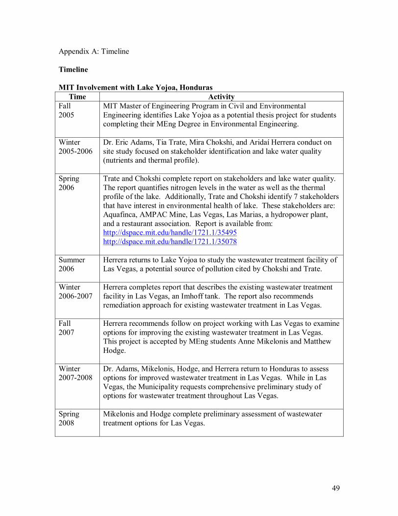
49
Appendix A: Timeline Timeline MIT Involvement with Lake Yojoa, Honduras
Time Activity Fall 2005
MIT Master of Engineering Program in Civil and Environmental Engineering identifies Lake Yojoa as a potential thesis project for students completing their MEng Degree in Environmental Engineering.
Winter 2005-2006
Dr. Eric Adams, Tia Trate, Mira Chokshi, and Aridaí Herrera conduct on site study focused on stakeholder identification and lake water quality (nutrients and thermal profile).
Spring 2006
Trate and Chokshi complete report on stakeholders and lake water quality. The report quantifies nitrogen levels in the water as well as the thermal profile of the lake. Additionally, Trate and Chokshi identify 7 stakeholders that have interest in environmental health of lake. These stakeholders are: Aquafinca, AMPAC Mine, Las Vegas, Las Marias, a hydropower plant, and a restaurant association. Report is available from: http://dspace.mit.edu/handle/1721.1/35495 http://dspace.mit.edu/handle/1721.1/35078
Summer 2006
Herrera returns to Lake Yojoa to study the wastewater treatment facility of Las Vegas, a potential source of pollution cited by Chokshi and Trate.
Winter 2006-2007
Herrera completes report that describes the existing wastewater treatment facility in Las Vegas, an Imhoff tank. The report also recommends remediation approach for existing wastewater treatment in Las Vegas.
Fall 2007
Herrera recommends follow on project working with Las Vegas to examine options for improving the existing wastewater treatment in Las Vegas. This project is accepted by MEng students Anne Mikelonis and Matthew Hodge.
Winter 2007-2008
Dr. Adams, Mikelonis, Hodge, and Herrera return to Honduras to assess options for improved wastewater treatment in Las Vegas. While in Las Vegas, the Municipality requests comprehensive preliminary study of options for wastewater treatment throughout Las Vegas.
Spring 2008
Mikelonis and Hodge complete preliminary assessment of wastewater treatment options for Las Vegas.

50
On Site Activities of Team in Winter 2007-2008 Date Activity January 7
Team of Aridaí Herrera, Anne Mikelonis, Matthew Hodge, and Dr. Eric Adams arrive in Honduras. Team meets with representative from NGO Water for People.
January 8
Team meets with Municipality of Las Vegas leadership including Mayor Carlos Fuentes and Chief Engineer Alexis Rodriguez. During the meeting, project goals are explained and refined.
January 9
Team meets with Aqua Finca Manager Israel Snir to update him on project and request assistance in finding lab equipment. Aqua Finca agrees to supply the use of an analytical balance during the team�s time in Honduras.
January 10
Team meets with Ramon Cordona, Infrastructure Director for the Honduran Social Investment Fund (FHIS) and Hugo Chavez, an engineer for FHIS, to discuss wastewater treatment in Honduras and the goals of the Las Vegas project.
January 11
Team examines another Imhoff tank in Marcala, Honduras. Team returns to Las Vegas to have second meeting with the Mayor and indicate the questions they will answer while on site. The questions they specify are: 1. Removal efficiency of the existing tank 2) Downstream water quality analysis 3) Options for sludge handling 4) Identification of local sources of coagulants 5) CEPT (chemically enhanced primary treatment) testing (bench and/or pilot scale) 6) Conceptual design of a full scale system for CEPT application
January 12
Team visits El Progreso and La Lima at the recommendation of FHIS to see good examples of popular treatment technology, waste stabilization ponds. Herrera and Dr. Adams return to the United States.
January 15� 22
Team collects influent and effluent water samples, measures flow and conduct jar tests to determine appropriate dosing of chemicals for CEPT pilot test on Imhoff tank. Hodge begins to collect necessary information for preliminary design of wastewater treatment system for Las Vegas. Mikelonis designs pilot test for CEPT.

51
January 23
Team meets with original contractor that built Imhoff tank in Las Vegas, Agua Para el Pueblo (APP) and acquires original design drawings of tank. Team also meets with Pedro Ortiz, a senior manager for the National Agency of Water Supply and Sewerage (SANAA) to discuss wastewater treatment in Honduras.
January 24-28
Hodge conducts preliminary screening of appropriate wastewater treatment technologies for Honduras and Mikelonis prepares to conduct pilot test of CEPT in Imhoff tank.
January 29
Team conducts pilot test of CEPT in Imhoff tank.
January 31
Team makes final presentation to Mayor and municipal staff of Las Vegas.
February 1
Team meets with AMPAC Mine and presents findings to engineering staff of mine at the request of the Mayor of Las Vegas.
February 2
Mikelonis and Hodge return to the United States.

52
Appendix B: Collected Data Flow
Date Time Depth (m)
Time (s)
Distance (m)
Flow (m3/hr)
16-Jan 9:30AM 0.184 56 50 184 16-Jan 9:30AM 0.184 51 50 169 16-Jan 2:30PM 0.191 55 50 189 16-Jan 2:30PM 0.191 56 50 192 17-Jan 4:30AM 0.121 53 50 103 17-Jan 10:00AM 0.184 52 50 172 19-Jan 2:00PM 0.165 56 50 161 20-Jan 10:00AM 0.178 57 50 180 21-Jan 9:30AM 0.165 57 50 164 25-Jan 3:00PM 0.153 55 50 145 29-Jan 10:45AM 0.203 46 50 169 29-Jan 12:00PM 0.178 49 50 156 29-Jan 12:30PM 0.178 47 50 150
Notes: Total Suspended Solids
Date Time TSSinf (mg/L)
TSSeff (mg/L)
15-Jan 9:30AM 700 200 15-Jan 9:30AM -- 400 17-Jan 10:00AM 200 160 17-Jan 10:00AM 200 140 29-Jan 10:45AM 200 130 29-Jan 10:45AM 220 110
Notes: - The only available analytical balance had three significant figures of accuracy (0.000g). This limited the accuracy of testing to 10 mg/L. - For each set of two tests, the influent and effluent should be averaged and then compared to determine removal rates.
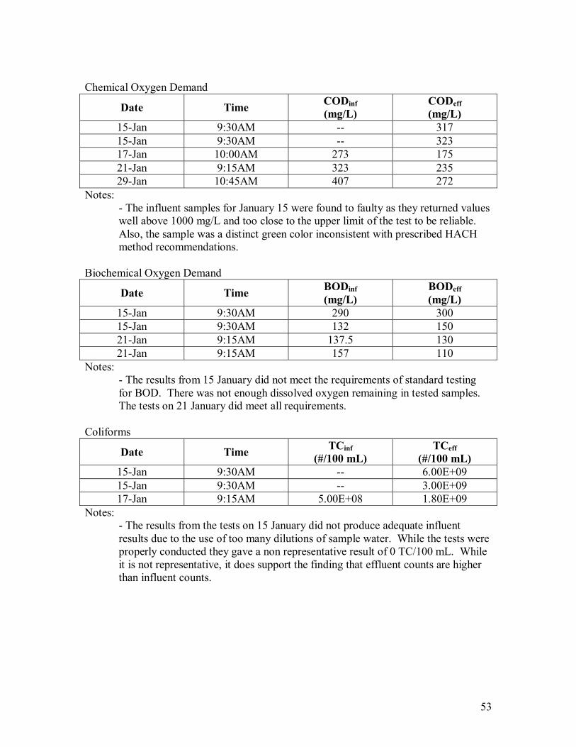
53
Chemical Oxygen Demand
Date Time CODinf (mg/L)
CODeff (mg/L)
15-Jan 9:30AM -- 317 15-Jan 9:30AM -- 323 17-Jan 10:00AM 273 175 21-Jan 9:15AM 323 235 29-Jan 10:45AM 407 272
Notes: - The influent samples for January 15 were found to faulty as they returned values well above 1000 mg/L and too close to the upper limit of the test to be reliable. Also, the sample was a distinct green color inconsistent with prescribed HACH method recommendations.
Biochemical Oxygen Demand
Date Time BODinf (mg/L)
BODeff (mg/L)
15-Jan 9:30AM 290 300 15-Jan 9:30AM 132 150 21-Jan 9:15AM 137.5 130 21-Jan 9:15AM 157 110
Notes: - The results from 15 January did not meet the requirements of standard testing for BOD. There was not enough dissolved oxygen remaining in tested samples. The tests on 21 January did meet all requirements.
Coliforms
Date Time TCinf (#/100 mL)
TCeff (#/100 mL)
15-Jan 9:30AM -- 6.00E+09 15-Jan 9:30AM -- 3.00E+09 17-Jan 9:15AM 5.00E+08 1.80E+09
Notes: - The results from the tests on 15 January did not produce adequate influent results due to the use of too many dilutions of sample water. While the tests were properly conducted they gave a non representative result of 0 TC/100 mL. While it is not representative, it does support the finding that effluent counts are higher than influent counts.
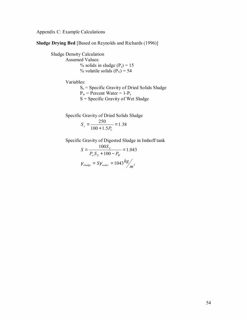
54
Appendix C: Example Calculations Sludge Drying Bed [Based on Reynolds and Richards (1996)] Sludge Density Calculation Assumed Values: % solids in sludge (Ps) = 15 % volatile solids (PV) = 54 Variables: Ss = Specific Gravity of Dried Solids Sludge Pw = Percent Water = 1-Ps
S = Specific Gravity of Wet Sludge Specific Gravity of Dried Solids Sludge
38.15.1100
250 =+
=V
s PS
Specific Gravity of Digested Sludge in Imhoff tank
31043
043.1100
100
mkgS
PSPS
S
watersludge
WSw
S
==
=−+
=
γγ
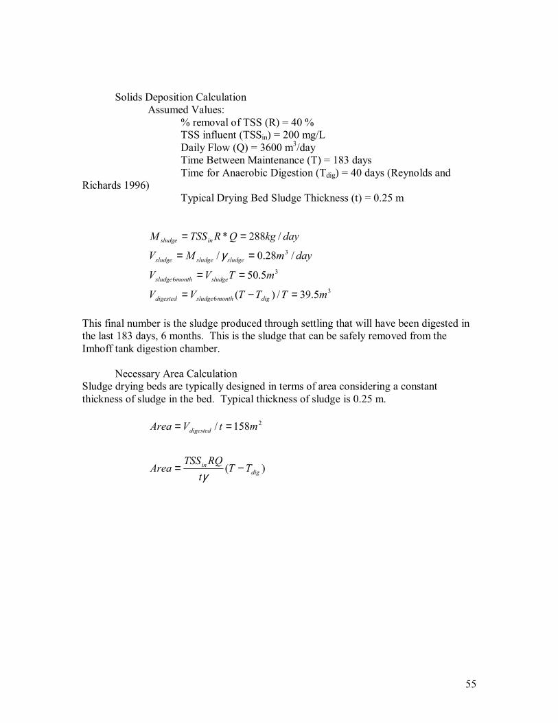
55
Solids Deposition Calculation Assumed Values: % removal of TSS (R) = 40 % TSS influent (TSSin) = 200 mg/L Daily Flow (Q) = 3600 m3/day Time Between Maintenance (T) = 183 days Time for Anaerobic Digestion (Tdig) = 40 days (Reynolds and Richards 1996) Typical Drying Bed Sludge Thickness (t) = 0.25 m
36
36
3
5.39/)(
5.50
/28.0/
/288*
mTTTVV
mTVV
daymMV
daykgQRTSSM
digmonthsludgedigested
sludgemonthsludge
sludgesludgesludge
insludge
=−=
==
==
==
γ
This final number is the sludge produced through settling that will have been digested in the last 183 days, 6 months. This is the sludge that can be safely removed from the Imhoff tank digestion chamber. Necessary Area Calculation Sludge drying beds are typically designed in terms of area considering a constant thickness of sludge in the bed. Typical thickness of sludge is 0.25 m.
)(
158/ 2
digin
digested
TTt
RQTSSArea
mtVArea
−=
==
γ
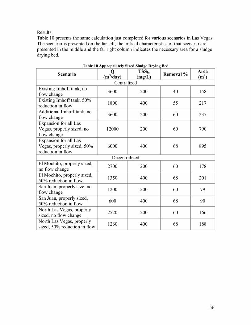
56
Results: Table 10 presents the same calculation just completed for various scenarios in Las Vegas. The scenario is presented on the far left, the critical characteristics of that scenario are presented in the middle and the far right column indicates the necessary area for a sludge drying bed.
Table 10 Appropriately Sized Sludge Drying Bed
Scenario Q (m3/day)
TSSin (mg/L) Removal % Area
(m2) Centralized
Existing Imhoff tank, no flow change 3600 200 40 158
Existing Imhoff tank, 50% reduction in flow 1800 400 55 217
Additional Imhoff tank, no flow change 3600 200 60 237
Expansion for all Las Vegas, properly sized, no flow change
12000 200 60 790
Expansion for all Las Vegas, properly sized, 50% reduction in flow
6000 400 68 895
Decentralized El Mochito, properly sized, no flow change 2700 200 60 178
El Mochito, properly sized, 50% reduction in flow 1350 400 68 201
San Juan, properly size, no flow change 1200 200 60 79
San Juan, properly sized, 50% reduction in flow 600 400 68 90
North Las Vegas, properly sized, no flow change 2520 200 60 166
North Las Vegas, properly sized, 50% reduction in flow 1260 400 68 188
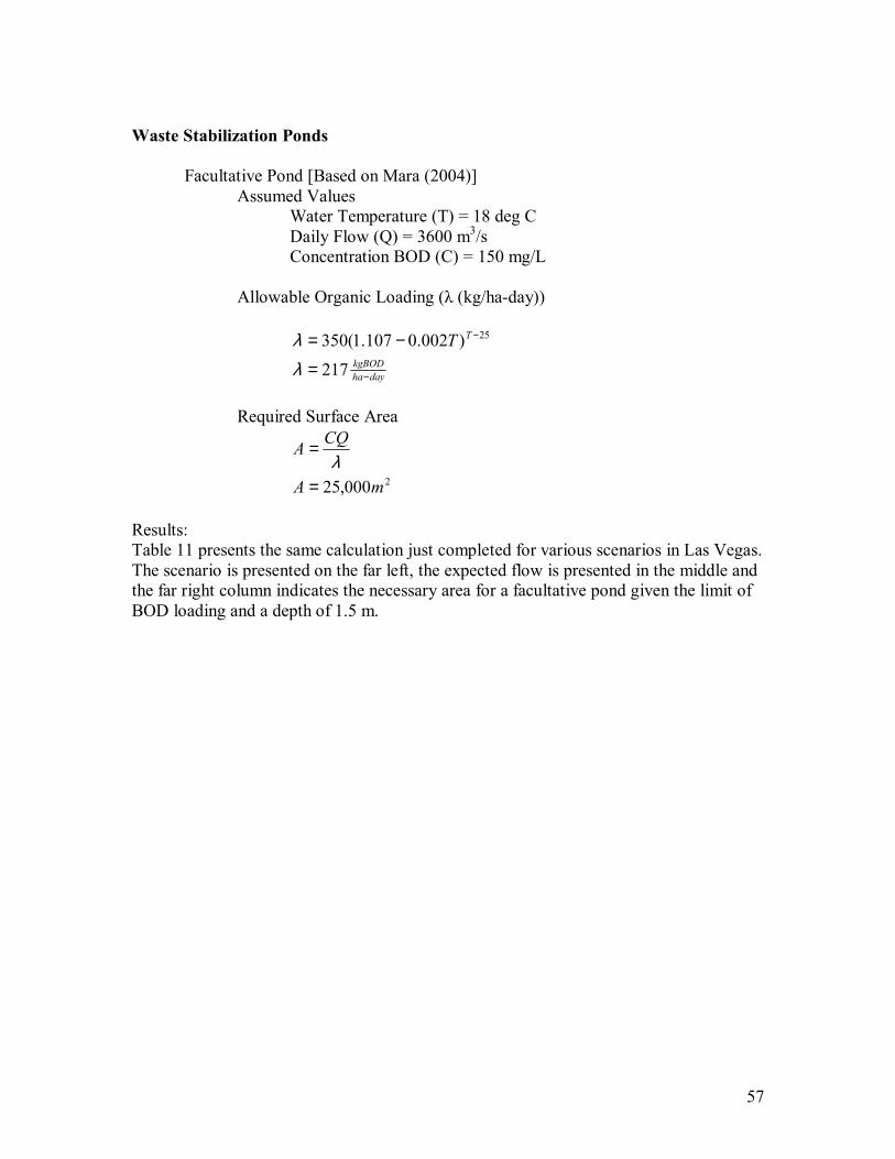
57
Waste Stabilization Ponds Facultative Pond [Based on Mara (2004)] Assumed Values Water Temperature (T) = 18 deg C Daily Flow (Q) = 3600 m3/s Concentration BOD (C) = 150 mg/L Allowable Organic Loading (λ (kg/ha-day))
dayha
kgBOD
TT
−
−
=
−=
217
)002.0107.1(350 25
λλ
Required Surface Area
2000,25 mA
CQA
=
=λ
Results: Table 11 presents the same calculation just completed for various scenarios in Las Vegas. The scenario is presented on the far left, the expected flow is presented in the middle and the far right column indicates the necessary area for a facultative pond given the limit of BOD loading and a depth of 1.5 m.

58
Table 11 Appropriately Sized Facultative Pond
Scenario Q (m3/day)
BOD (mg/L)
Area (m2)
Centralized Central Las Vegas, no flow change 3600 150 25000
Central Las Vegas, 50% reduction in flow 1800 300 25000
Expansion for all Las Vegas, properly sized, no flow change 12000 150 83340
Expansion for all Las Vegas, properly sized, 50% reduction in flow
6000 300 83340
Decentralized El Mochito, properly sized, no flow change 2700 150 18750
El Mochito, properly sized, 50% reduction in flow 1350 300 18750
San Juan, properly sized, no flow change 1200 150 8340
San Juan, properly sized, 50% reduction in flow 600 300 8340
North Las Vegas, properly sized, no flow change 2520 150 17500
North Las Vegas, properly sized, 50% reduction in flow 1260 300 17500
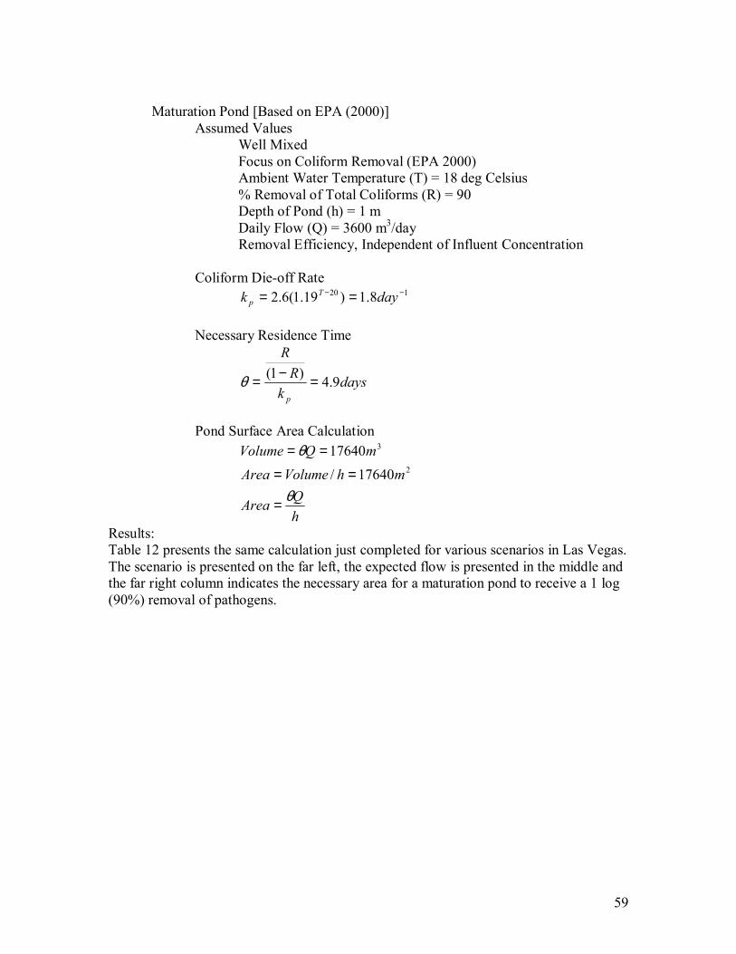
59
Maturation Pond [Based on EPA (2000)] Assumed Values Well Mixed Focus on Coliform Removal (EPA 2000) Ambient Water Temperature (T) = 18 deg Celsius % Removal of Total Coliforms (R) = 90 Depth of Pond (h) = 1 m Daily Flow (Q) = 3600 m3/day Removal Efficiency, Independent of Influent Concentration Coliform Die-off Rate 120 8.1)19.1(6.2 −− == dayk T
p
Necessary Residence Time
daysk
RR
p
9.4)1( =−=θ
Pond Surface Area Calculation
hQArea
mhVolumeAreamQVolume
θ
θ
=
==
==2
3
17640/17640
Results: Table 12 presents the same calculation just completed for various scenarios in Las Vegas. The scenario is presented on the far left, the expected flow is presented in the middle and the far right column indicates the necessary area for a maturation pond to receive a 1 log (90%) removal of pathogens.
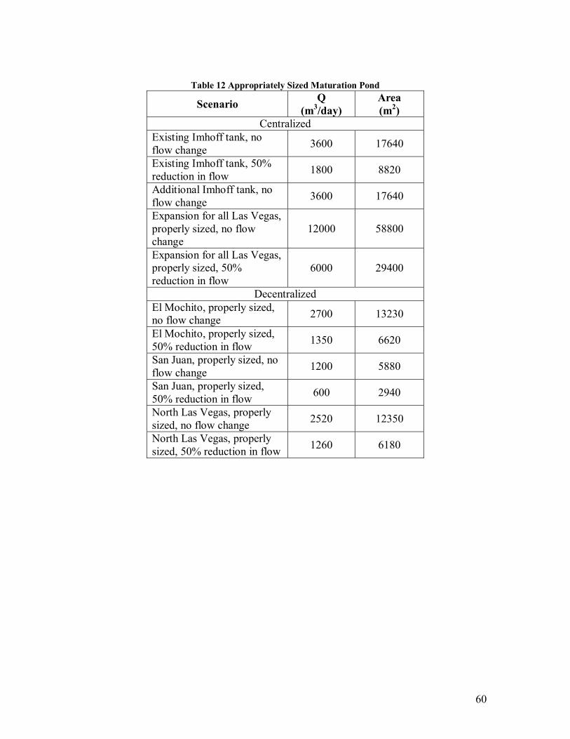
60
Table 12 Appropriately Sized Maturation Pond
Scenario Q (m3/day)
Area (m2)
Centralized Existing Imhoff tank, no flow change 3600 17640
Existing Imhoff tank, 50% reduction in flow 1800 8820
Additional Imhoff tank, no flow change 3600 17640
Expansion for all Las Vegas, properly sized, no flow change
12000 58800
Expansion for all Las Vegas, properly sized, 50% reduction in flow
6000 29400
Decentralized El Mochito, properly sized, no flow change 2700 13230
El Mochito, properly sized, 50% reduction in flow 1350 6620
San Juan, properly sized, no flow change 1200 5880
San Juan, properly sized, 50% reduction in flow 600 2940
North Las Vegas, properly sized, no flow change 2520 12350
North Las Vegas, properly sized, 50% reduction in flow 1260 6180
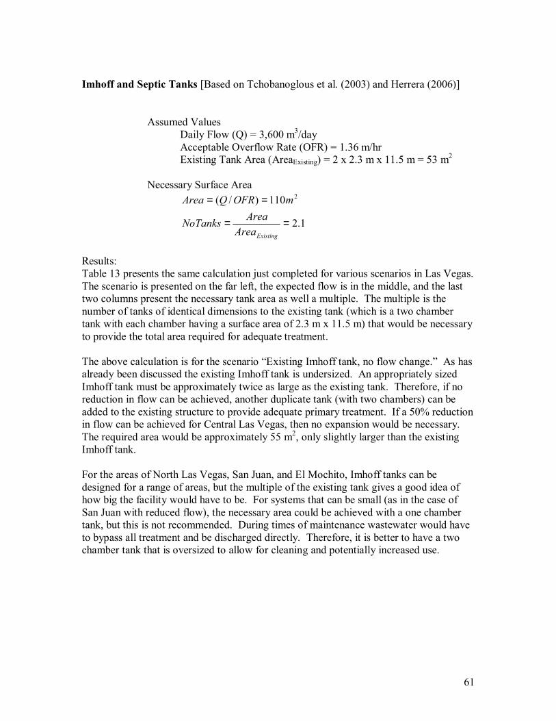
61
Imhoff and Septic Tanks [Based on Tchobanoglous et al. (2003) and Herrera (2006)] Assumed Values
Daily Flow (Q) = 3,600 m3/day Acceptable Overflow Rate (OFR) = 1.36 m/hr Existing Tank Area (AreaExisting) = 2 x 2.3 m x 11.5 m = 53 m2
Necessary Surface Area
1.2
110)/( 2
==
==
ExistingAreaAreaNoTanks
mOFRQArea
Results: Table 13 presents the same calculation just completed for various scenarios in Las Vegas. The scenario is presented on the far left, the expected flow is in the middle, and the last two columns present the necessary tank area as well a multiple. The multiple is the number of tanks of identical dimensions to the existing tank (which is a two chamber tank with each chamber having a surface area of 2.3 m x 11.5 m) that would be necessary to provide the total area required for adequate treatment. The above calculation is for the scenario �Existing Imhoff tank, no flow change.� As has already been discussed the existing Imhoff tank is undersized. An appropriately sized Imhoff tank must be approximately twice as large as the existing tank. Therefore, if no reduction in flow can be achieved, another duplicate tank (with two chambers) can be added to the existing structure to provide adequate primary treatment. If a 50% reduction in flow can be achieved for Central Las Vegas, then no expansion would be necessary. The required area would be approximately 55 m2, only slightly larger than the existing Imhoff tank. For the areas of North Las Vegas, San Juan, and El Mochito, Imhoff tanks can be designed for a range of areas, but the multiple of the existing tank gives a good idea of how big the facility would have to be. For systems that can be small (as in the case of San Juan with reduced flow), the necessary area could be achieved with a one chamber tank, but this is not recommended. During times of maintenance wastewater would have to bypass all treatment and be discharged directly. Therefore, it is better to have a two chamber tank that is oversized to allow for cleaning and potentially increased use.
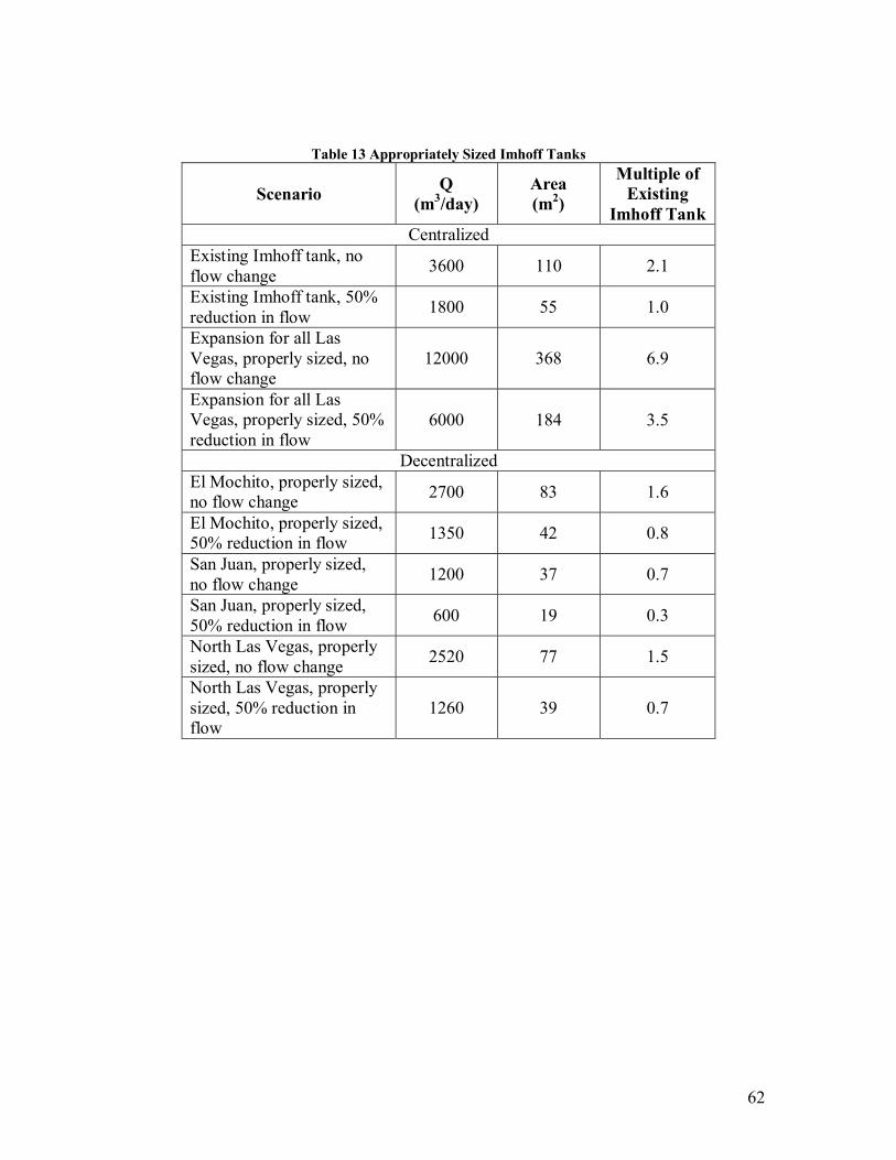
62
Table 13 Appropriately Sized Imhoff Tanks
Scenario Q (m3/day)
Area (m2)
Multiple of Existing
Imhoff Tank Centralized
Existing Imhoff tank, no flow change 3600 110 2.1
Existing Imhoff tank, 50% reduction in flow 1800 55 1.0
Expansion for all Las Vegas, properly sized, no flow change
12000 368 6.9
Expansion for all Las Vegas, properly sized, 50% reduction in flow
6000 184 3.5
Decentralized El Mochito, properly sized, no flow change 2700 83 1.6
El Mochito, properly sized, 50% reduction in flow 1350 42 0.8
San Juan, properly sized, no flow change 1200 37 0.7
San Juan, properly sized, 50% reduction in flow 600 19 0.3
North Las Vegas, properly sized, no flow change 2520 77 1.5
North Las Vegas, properly sized, 50% reduction in flow
1260 39 0.7