wastewater reuse ro plant: road from troubled …membranes.com/docs/papers/new folder/wastewater...
TRANSCRIPT
The International Desalination Association World Congress on Desalination and Water Reuse 2013 / Tianjin, China REF: IDAWC/TIAN13-093
WASTEWATER REUSE RO PLANT: ROAD FROM TROUBLED TO STABLE OPERATION Authors: Craig Bartels, PhD, Roman Boda, Ahmed Abrar Presenter: Dr.Craig Bartels Vice President of Technology – Hydranautics - U.S.A [email protected] Abstract Operation of wastewater treatment plants can be very challenging due to the high fouling tendency of wastewater. Much knowledge has been gained over the past few years to guide design engineers on the optimum design for wastewater RO plants. The implementation of this knowledge is helping to improve the operation and performance of many wastewater plants. One example of this is the SAFI (BESIX Group Company) plant in Ajman, UAE. Here a recent plant has been installed to treat sewage effluent in order to supply high quality water for reuse. The 1.8 million US gallons per day (6,800 m3/d) plant treats conventionally treated municipal effluent with microfiltration (MF) and reverse osmosis (RO). There are two RO trains designed to operate at 10.9 gfd (18.6 lmh) and 75% recovery, while treating a feedwater with approximately 4000 mg/l of total dissolved solids (TDS). When operation started in 2010, the rate of fouling was extremely high, up to 66% flow decline in 3 months of operation. This was eventually attributed to higher than design operation temperatures, lack of regular biocide disinfection, and no flux balance between the RO stages. A detailed analysis was made of the fouled elements, and it was found that the primary issue was biofouling. This paper will review the actions that were taken to correct the fouling issue and stabilize RO operation. One of the key factors which ultimately resolved the problem was the membrane change made to better balance the flux between RO stages. This and other changes have resulted in the plant now achieving stable operation and production goals.
The International Desalination Association (IDA) World Congress on Desalination and Water Reuse
REF: IDAWC/TIAN13- 093 -- 2 --
I. INTRODUCTION Whilst large quantities of Treated Sewage Effluent (TSE) are being produced all over the Middle East, the reuse of TSE seems to be limited so far to certain restricted irrigation projects with limited cost recovery. This project is a public private partnership between the Municipality of Ajman and the Belgian company BESIX. It is SAFI’s aim to be a pioneer in its field by operating a reuse scheme on a full cost recovery basis. Its customers comprise READYMIX, district cooling and cleaning companies. Going forward, SAFI aims to diversify its product water to include also potable use. In order to address cultural concerns and seasonality in demand, a scheme comprising underground aquifer storage is also being considered. SAFI, located in the Emirate of Ajman (UAE), is the first plant in the region that brings the concept of commercialized “water reuse” fully into practice. It is a sustainable alternative to the use of well or desalinated sea water. The plant reclaims tertiary treated wastewater from the Ajman Sewage Treatment Plant, by further polishing it with microfiltration (MF) and reverse osmosis (RO) processes. The plant currently has a design production capacity of 1.8 million USG (6,800 m3) per day. The RO plant was designed and initially equipped with high rejection, low fouling brackish water RO membranes1, which were designed for use on difficult feed water with high organic content that is typical for surface or municipal wastewater sources. This type of membrane is also used on other wastewater re-use plants in other parts of the world like Singapore and Spain. The plant was commissioned in 2010, but the initial operation of RO plant was not trouble-free. A large combined effort by the plant operator, as well as the membrane and cleaning chemicals suppliers had to be used to bring plant operation into today’s status. The plant was initially suffering from heavy fouling of the RO membranes and very soon after star-up the RO trains lost a large portion of their production flow. This paper will present a review of the road from initial troubled operation to present successful operation of SAFI plant with focus on RO part and more detailed description of steps taken to improve operation of RO membranes. II. RO PLANT DESIGN PARAMETERS Design parameters of SAFI RO plant are summarized in Table 1 below:
Table 1 – RO Plant Design Parameters Feed water source Tertiary treated municipal effluent from Ajman WWTP Pre-treatment before RO Microfiltration Design feed water TDS 3,987 mg/l Design RO capacity 694 GMP (3,785 m3/day) per RO train Number of RO trains 2 Design RO array configuration Stage 1 - 24 pressure vessels x 6 elements Stage 2 - 12 pressure vessels x 6 elements Design RO average flux 10.9 GFD (18.6 l/m2h) Design water temperature 25oC Design RO recovery 75% RO element type on both stages High Rejection, Low Fouling BWRO1
1 Hydranautics LFC3-LD
The International Desalination Association (IDA) World Congress on Desalination and Water Reuse
REF: IDAWC/TIAN13- 093 -- 3 --
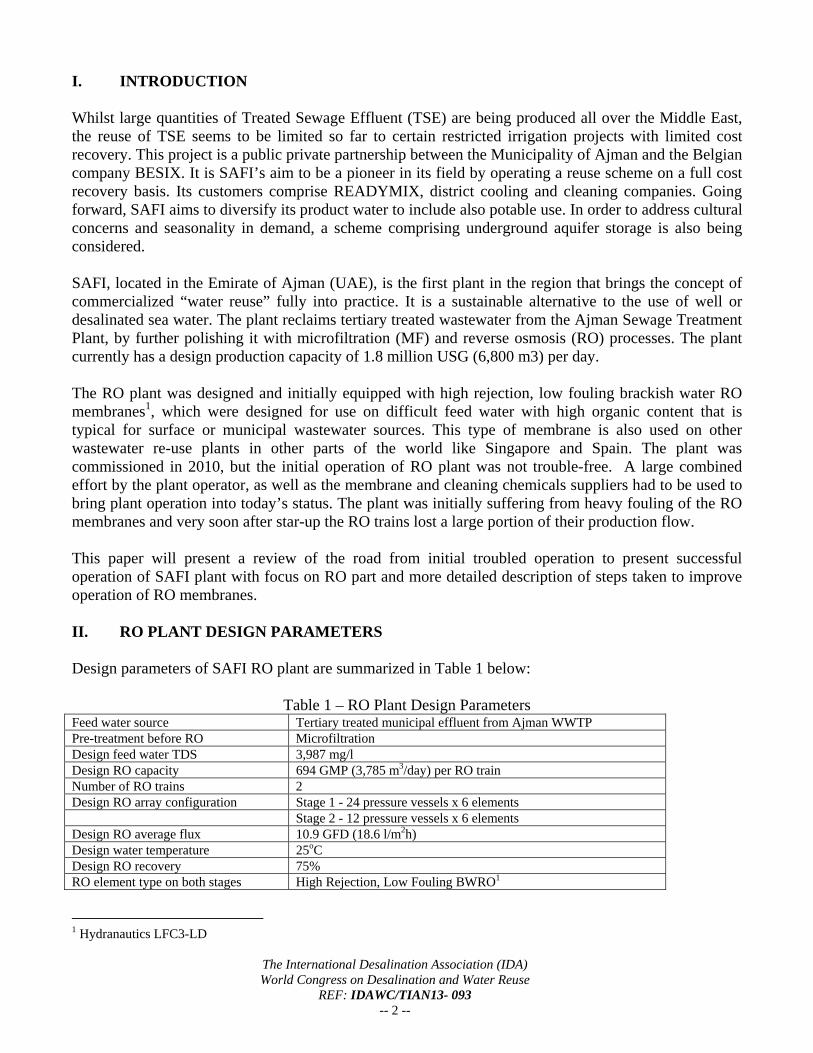
III. RO PLANT INITIAL OPERATION The SAFI RO plant was commissioned in March 2010 and operation of RO train No.1 started on March 26, 2010. Operating recovery at startup was kept low at 50% and it was slowly increased to 65% until June 2010. Permeate flow was not at design values, but only at 400 – 500 gpm (91 – 114 m3/h), which corresponds to flux of 6 – 8 GFD (10.2 – 13.6 l/m2h). Despite this conservative operation, the performance of RO was rapidly deteriorating and the unit lost 30% of normalized permeate flow until middle of September (Figures 1 - 3).
Figure 1 – RO1 Normalized Permeate Flow Before Replacement
0.00
100.00
200.00
300.00
400.00
500.00
600.00
700.00
800.00
900.00
gp
m
Date
Perm Flow Norm. vs Actual Qp Norm. Qp Actual
AIMS RO 1
LFC3‐LD
Design Permeate Flow = 694 gpm (157.7 m3/h)
- 30%
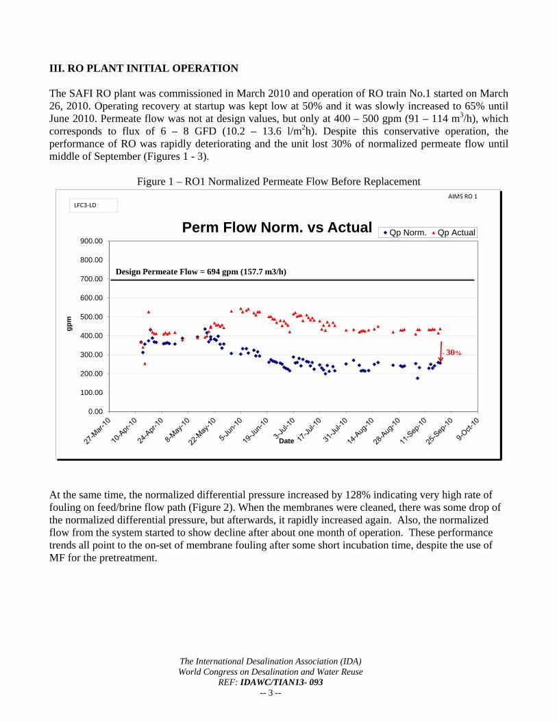
At the same time, the normalized differential pressure increased by 128% indicating very high rate of fouling on feed/brine flow path (Figure 2). When the membranes were cleaned, there was some drop of the normalized differential pressure, but afterwards, it rapidly increased again. Also, the normalized flow from the system started to show decline after about one month of operation. These performance trends all point to the on-set of membrane fouling after some short incubation time, despite the use of MF for the pretreatment.
The International Desalination Association (IDA) World Congress on Desalination and Water Reuse
REF: IDAWC/TIAN13- 093 -- 4 --
Figure 2 – RO1 Normalized Differential Pressure Before Replacement
0.00
20.00
40.00
60.00
80.00
100.00
120.00
140.00
160.00
ps
i
Date
Differential Pres. Norm. dP Norm.
AIMS RO 1LFC3‐LD
+ 128%
Figure 3 – RO2 Normalized Permeate Flow Before Replacement
0.00
100.00
200.00
300.00
400.00
500.00
600.00
700.00
800.00
900.00
gp
m
Date
Perm Flow Norm. vs Actual Qp Norm. Qp Actual
AIMS RO 2LFC3‐LD
Design Permeate Flow - 694 gpm (157.7 m3/h)
- 66%
The International Desalination Association (IDA) World Congress on Desalination and Water Reuse
REF: IDAWC/TIAN13- 093 -- 5 --
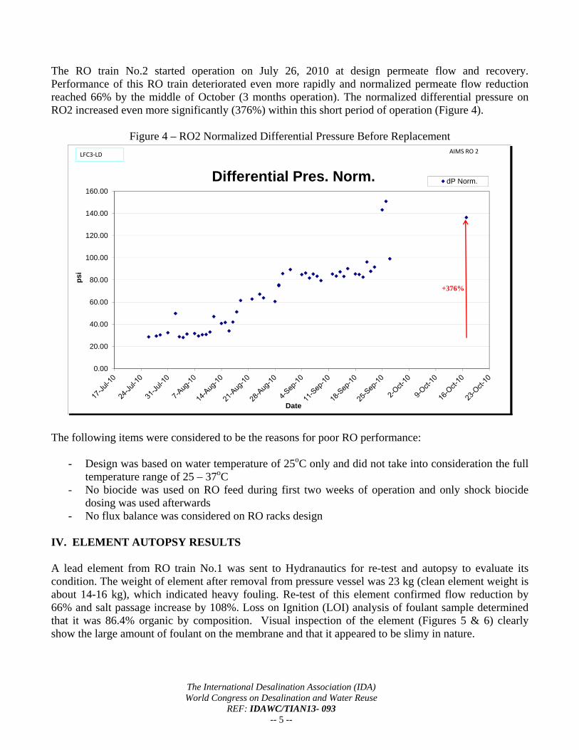
The RO train No.2 started operation on July 26, 2010 at design permeate flow and recovery. Performance of this RO train deteriorated even more rapidly and normalized permeate flow reduction reached 66% by the middle of October (3 months operation). The normalized differential pressure on RO2 increased even more significantly (376%) within this short period of operation (Figure 4).
Figure 4 – RO2 Normalized Differential Pressure Before Replacement
0.00
20.00
40.00
60.00
80.00
100.00
120.00
140.00
160.00
psi
Date
Differential Pres. Norm. dP Norm.
AIMS RO 2LFC3‐LD
+376%
The following items were considered to be the reasons for poor RO performance:
- Design was based on water temperature of 25oC only and did not take into consideration the full temperature range of 25 – 37oC
- No biocide was used on RO feed during first two weeks of operation and only shock biocide dosing was used afterwards
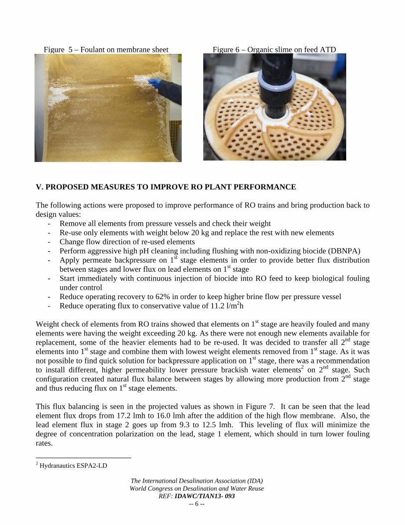
- No flux balance was considered on RO racks design IV. ELEMENT AUTOPSY RESULTS A lead element from RO train No.1 was sent to Hydranautics for re-test and autopsy to evaluate its condition. The weight of element after removal from pressure vessel was 23 kg (clean element weight is about 14-16 kg), which indicated heavy fouling. Re-test of this element confirmed flow reduction by 66% and salt passage increase by 108%. Loss on Ignition (LOI) analysis of foulant sample determined that it was 86.4% organic by composition. Visual inspection of the element (Figures 5 & 6) clearly show the large amount of foulant on the membrane and that it appeared to be slimy in nature.
The International Desalination Association (IDA) World Congress on Desalination and Water Reuse
REF: IDAWC/TIAN13- 093 -- 6 --
Figure 5 – Foulant on membrane sheet Figure 6 – Organic slime on feed ATD V. PROPOSED MEASURES TO IMPROVE RO PLANT PERFORMANCE The following actions were proposed to improve performance of RO trains and bring production back to design values:
- Remove all elements from pressure vessels and check their weight - Re-use only elements with weight below 20 kg and replace the rest with new elements - Change flow direction of re-used elements - Perform aggressive high pH cleaning including flushing with non-oxidizing biocide (DBNPA) - Apply permeate backpressure on 1st stage elements in order to provide better flux distribution
between stages and lower flux on lead elements on 1st stage - Start immediately with continuous injection of biocide into RO feed to keep biological fouling
under control - Reduce operating recovery to 62% in order to keep higher brine flow per pressure vessel - Reduce operating flux to conservative value of 11.2 l/m2h
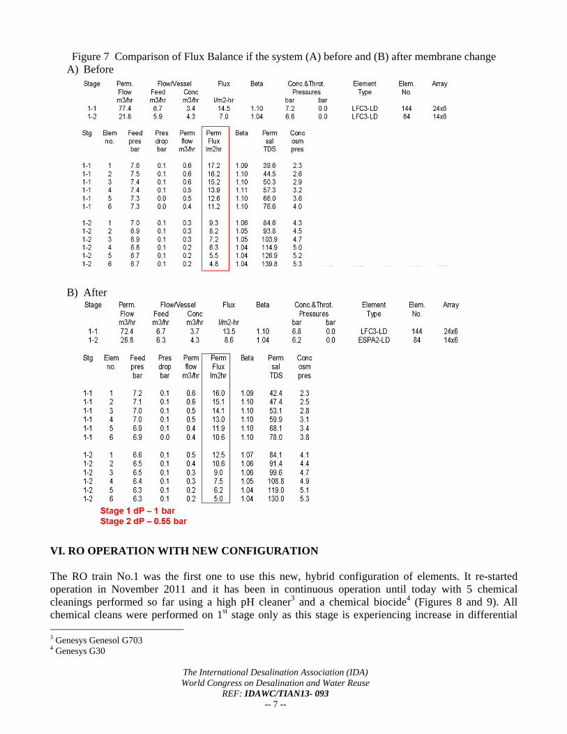
Weight check of elements from RO trains showed that elements on 1st stage are heavily fouled and many elements were having the weight exceeding 20 kg. As there were not enough new elements available for replacement, some of the heavier elements had to be re-used. It was decided to transfer all 2nd stage elements into 1st stage and combine them with lowest weight elements removed from 1st stage. As it was not possible to find quick solution for backpressure application on 1st stage, there was a recommendation to install different, higher permeability lower pressure brackish water elements2 on 2nd stage. Such configuration created natural flux balance between stages by allowing more production from 2nd stage and thus reducing flux on 1st stage elements. This flux balancing is seen in the projected values as shown in Figure 7. It can be seen that the lead element flux drops from 17.2 lmh to 16.0 lmh after the addition of the high flow membrane. Also, the lead element flux in stage 2 goes up from 9.3 to 12.5 lmh. This leveling of flux will minimize the degree of concentration polarization on the lead, stage 1 element, which should in turn lower fouling rates.
2 Hydranautics ESPA2-LD
The International Desalination Association (IDA) World Congress on Desalination and Water Reuse
REF: IDAWC/TIAN13- 093 -- 7 --
Figure 7 Comparison of Flux Balance if the system (A) before and (B) after membrane change A) Before
B) After
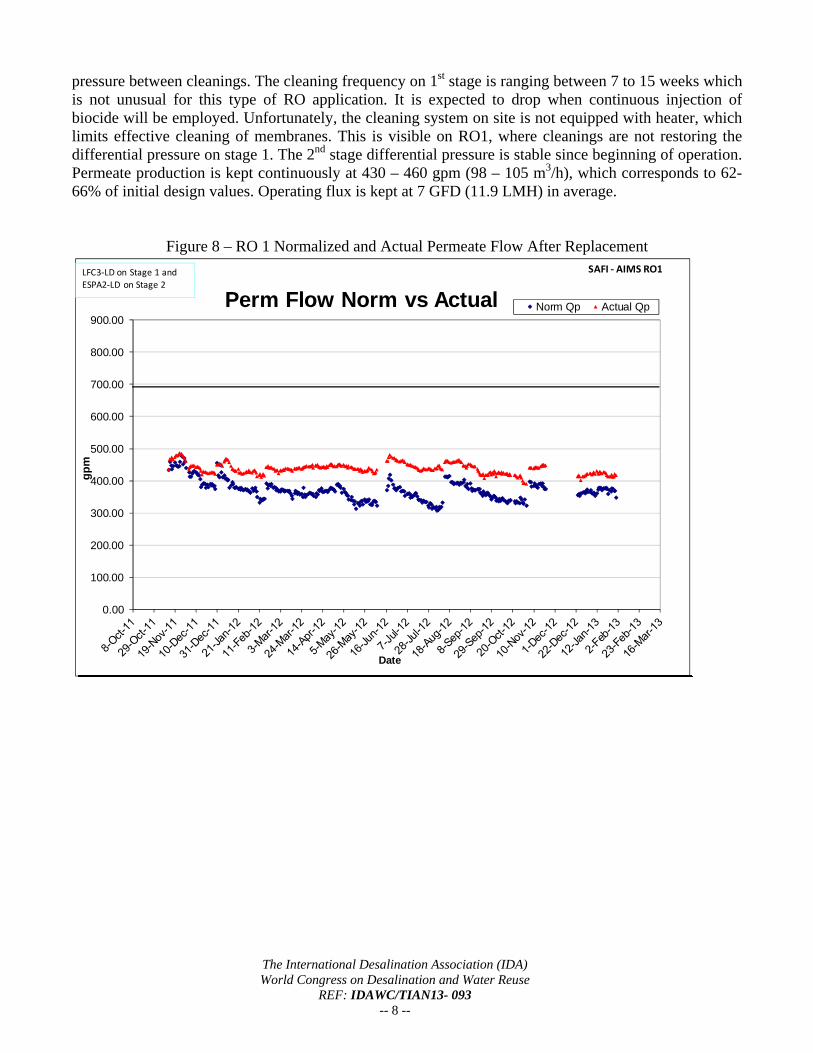
VI. RO OPERATION WITH NEW CONFIGURATION The RO train No.1 was the first one to use this new, hybrid configuration of elements. It re-started operation in November 2011 and it has been in continuous operation until today with 5 chemical cleanings performed so far using a high pH cleaner3 and a chemical biocide4 (Figures 8 and 9). All chemical cleans were performed on 1st stage only as this stage is experiencing increase in differential 3 Genesys Genesol G703 4 Genesys G30
The International Desalination Association (IDA) World Congress on Desalination and Water Reuse
REF: IDAWC/TIAN13- 093 -- 8 --
pressure between cleanings. The cleaning frequency on 1st stage is ranging between 7 to 15 weeks which is not unusual for this type of RO application. It is expected to drop when continuous injection of biocide will be employed. Unfortunately, the cleaning system on site is not equipped with heater, which limits effective cleaning of membranes. This is visible on RO1, where cleanings are not restoring the differential pressure on stage 1. The 2nd stage differential pressure is stable since beginning of operation. Permeate production is kept continuously at 430 – 460 gpm (98 – 105 m3/h), which corresponds to 62-66% of initial design values. Operating flux is kept at 7 GFD (11.9 LMH) in average.
Figure 8 – RO 1 Normalized and Actual Permeate Flow After Replacement
0.00
100.00
200.00
300.00
400.00
500.00
600.00
700.00
800.00
900.00
gp
m
Date
Perm Flow Norm vs Actual Norm Qp Actual Qp
SAFI ‐ AIMS RO1LFC3‐LD on Stage 1 and
ESPA2‐LD on Stage 2
The International Desalination Association (IDA) World Congress on Desalination and Water Reuse
REF: IDAWC/TIAN13- 093 -- 9 --
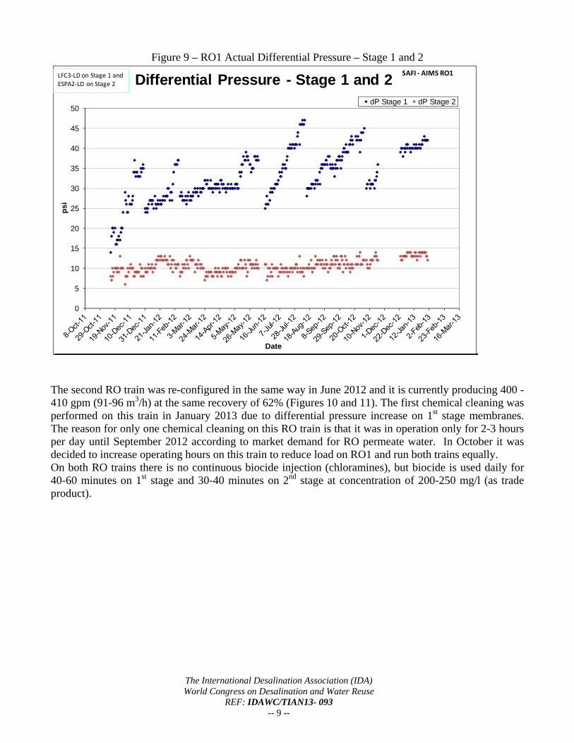
Figure 9 – RO1 Actual Differential Pressure – Stage 1 and 2
0
5
10
15
20
25
30
35
40
45
50
ps
i
Date
Differential Pressure - Stage 1 and 2dP Stage 1 dP Stage 2
SAFI ‐ AIMS RO1LFC3‐LD on Stage 1 and
ESPA2‐LD on Stage 2
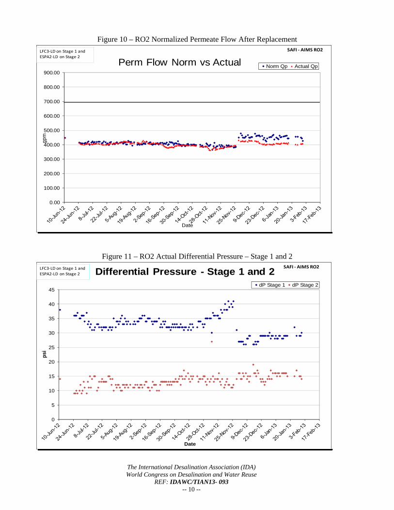
The second RO train was re-configured in the same way in June 2012 and it is currently producing 400 - 410 gpm (91-96 m3/h) at the same recovery of 62% (Figures 10 and 11). The first chemical cleaning was performed on this train in January 2013 due to differential pressure increase on 1st stage membranes. The reason for only one chemical cleaning on this RO train is that it was in operation only for 2-3 hours per day until September 2012 according to market demand for RO permeate water. In October it was decided to increase operating hours on this train to reduce load on RO1 and run both trains equally. On both RO trains there is no continuous biocide injection (chloramines), but biocide is used daily for 40-60 minutes on 1st stage and 30-40 minutes on 2nd stage at concentration of 200-250 mg/l (as trade product).
The International Desalination Association (IDA) World Congress on Desalination and Water Reuse
REF: IDAWC/TIAN13- 093 -- 10 --
Figure 10 – RO2 Normalized Permeate Flow After Replacement
0.00
100.00
200.00
300.00
400.00
500.00
600.00
700.00
800.00
900.00
gpm
Date
Perm Flow Norm vs Actual Norm Qp Actual Qp
SAFI ‐ AIMS RO2LFC3‐LD on Stage 1 and ESPA2‐LD on Stage 2
Figure 11 – RO2 Actual Differential Pressure – Stage 1 and 2
0
5
10
15
20
25
30
35
40
45
psi
Date
Differential Pressure - Stage 1 and 2dP Stage 1 dP Stage 2
SAFI ‐ AIMS RO2LFC3‐LD on Stage 1 and
ESPA2‐LD on Stage 2
The International Desalination Association (IDA) World Congress on Desalination and Water Reuse
REF: IDAWC/TIAN13- 093 -- 11 --
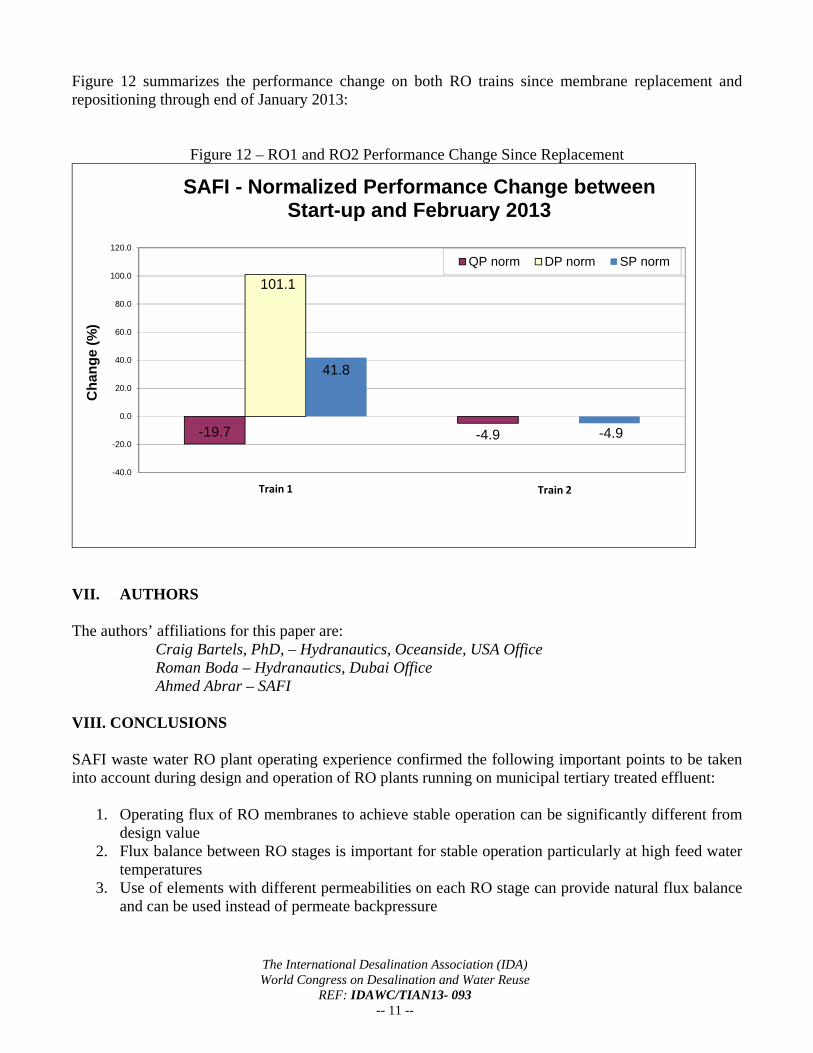
Figure 12 summarizes the performance change on both RO trains since membrane replacement and repositioning through end of January 2013:
Figure 12 – RO1 and RO2 Performance Change Since Replacement
-19.7 -4.9
101.1
41.8
-4.9
-40.0
-20.0
0.0
20.0
40.0
60.0
80.0
100.0
120.0
Ch
an
ge
(%
)
SAFI - Normalized Performance Change between Start-up and February 2013
QP norm DP norm SP norm
Train 1 Train 2
VII. AUTHORS The authors’ affiliations for this paper are: Craig Bartels, PhD, – Hydranautics, Oceanside, USA Office Roman Boda – Hydranautics, Dubai Office Ahmed Abrar – SAFI VIII. CONCLUSIONS SAFI waste water RO plant operating experience confirmed the following important points to be taken into account during design and operation of RO plants running on municipal tertiary treated effluent:
1. Operating flux of RO membranes to achieve stable operation can be significantly different from design value
2. Flux balance between RO stages is important for stable operation particularly at high feed water temperatures
3. Use of elements with different permeabilities on each RO stage can provide natural flux balance and can be used instead of permeate backpressure

The International Desalination Association (IDA) World Congress on Desalination and Water Reuse
REF: IDAWC/TIAN13- 093 -- 12 --
4. Continuous use of biocide on RO feed is essential for control of biological fouling and stable RO operation on this type of applications if when ultrafiltration is used as RO pre-treatment.
5. Heater on cleaning system is inevitable to obtain good cleaning efficiency particularly on feed water with high fouling potential.