waste isolation pilot plant compliance certification
TRANSCRIPT
Waste Isolation Pilot Plant
Compliance Certification Application
Reference 47
Beauheim, R.L., B. W. Hassinger, and J.A. Klaiber, 1983. Basic Data Report for Borehole Cabin Baby-1 Deepening and Hydrologic Testing, WTSD-TME-020, Albuquerque, NM, U. S. DOE.
Submitted in accordance with 40 CFR 4194.13, Submission of Reference Materials.


B A S I C DATA R E P O R T F O R B O R E H O L E C A B I N B A B Y - 1 D E E P E N I N G AND H Y D R O L O G I C T E S T I N G
W A S T E I S O L A T I O N P I L O T P L A N T ( W I P P ) P R O J E C T S O U T H E A S T E R N NEW M E X I C O
DECEMBER, 1983
DISCLAIMER
This report was prepwed as an account of work sponsored by an agency of the United States Government. Neither the United States Government nor any agency thenof, nor any of their cmployeca, makes any warranty, upreas or implied, or assumes any legal liability or nspollsi- bility for the accuracy, completcaas, or usefulness of any idormation, apparatus, product, or process diec1d, or rqmsmts that its use would not id* privatdy o d rights Refer- ence herein to any -C wmmcdd product, praxsa, or service by trade nomc, trademark, manufacturer, or oth& docs not aecessariy .constitute or imply its endorsement, raxrm- mendation, or favoring by the United States Government or any agency thereof. The views and opinions of authors expressed hmin do not nccmady state or reflect those of the United States Government or any agency thcreof.
U.S. D e p a r t m e n t of E n e r g y Waste I so la t ion P i l o t P l a n t
A l b u q u e r q u e , New M e x i c o
BASIC DATA REPORT FOR BOREHOLE CABIN BABY-1 DEEPENING AND HYDROLOGIC TESTING
WASTE ISOLATION PILOT PLANT (WIPP) PROJECT SOUTHEASTERN NEW MEXICO
Richard L. Beauheim Date
D'Appolonia Consulting Engineers, Inc.
D'Appolonia Consulting Engineers, Inc.
/
, J;/ /.$,da eya. Klaiber
r
D'Appolonia Consulting Engineers, Inc.
' 5/ Lo / 8-3
Date
D'Appolonia Consulting Engineers, Inc.
COG IZANT
Westinghouse Electric Corporation
Date

TABLE OF CONTENTS
BASIC DATA REPORT FOR BOREHOLE CABIN BABY-1 DEEPENING AND HYDROLOGIC TESTING
TABLE OF CONTENTS
LIST OF TABLES
LIST OF FIGURES
1.0 ABSTRACT
2.0 INTRODUCTION
2.1 THE PURPOSE OF THE WIPP
2.2 THE PURPOSE OF DEEPENING CABIN BABY-1
3.0 GEOLOGIC DATA
3.1 ABSTRACT
3.2 INTRODUCTION
3.3 DESCRIPTION OF CABIN BABY-1 DEEPENING
3.4 STRATIGRAPHY
4.0 HYDROLOGIC TESTING
4.1 PURPOSES OF TESTING
4.2 TEST INTERVAL SELECTION
4.3 TEST METHODS
4.4 INSTRUMENTATION
4.5 TEST DATA ANALYSIS METHODS
4.5.1 Flow P e r i o d Da ta A n a l y s i s
4.5.2 B u i l d u p P e r i o d Da ta A n a l y s i s
4.6 TEST RESULTS
4.6.1 DST-4178: Hays Sands tone
4.6.2 DST-4138: O lds S a n d s t o n e
4.6.3 DST-4100: Ramsey Sands tone
4.6.4 DST-4044: Lamar L imes tone
4.6.5 DST-765: S a l a d o Forma t ion
Page
i
iii
i v
1-1
2-1
2-1
2-2
3-1
3-1
3-1
3-2
3-4
4-1
4-1
4-2
4-3
4-5
4-6
4-6
4-8
4-9
4-9
4-10

TABLE OF CONTENTS ( c o n t i n u e d ) .
4 . 7 HYDROGEOCHEMICAL SAMPLING
4 . 7 . 1 Hays S a n d s t o n e F l u i d S a m p l i n g
4 . 7 . 2 O l d s S a n d s t o n e F l u i d S a m p l i n g
4 . 7 . 3 Ramsey S a n d s t o n e F l u i d S a m p l i n g
4 . 7 . 4 B e l l Canyon F l u i d S a m p l i n g
4 . 8 PRESENT WELL CONDITION
REFERENCES
TABLES
FIGURES
APPENDIX A - JUSTIFICATION
APPENDIX B - FIELD OPERATIONS PLAN
APPENDIX C - BOREHOLE HISTORY
P a g e
4 -13
4-1 5
4-15
4-1 6
4-17
4-1 8

LIST OF TABLES
TABLE NO. TITLE - 1 Abridged History of Borehole Cabin Baby-1
2 Stratigraphic Summary of Borehole Cabin Baby-1
3 Lithologic Log of Deepened Portion of Cabin Baby-1
4 Cabin Baby-1 Sperry-Sun Directional Survey
5 Hydrologic Testing Activity Summary
6 Summary of LIST Results
7 Chemical Composition of Fluids, Bell Canyon Formation, Cabin Baby-1

LIST OF FIGURES
FIGURE NO. TITLE
1 Location of the WIPP Site and Borehole Cabin Baby-1
2 Plan of the WIPP Site and Location of Borehole Cabin Baby-1
3 As-Built Conditions After Deepening Borehole Cabin Baby-1
4 Geophysical and Lithologic Logs for Cabin Baby-1
5 Cabin Baby-1 Borehole Orientation
6 Straddle Packer Assembly Configuration
Schematic Diagram of Data Acquisition System
Real-Time Plot of DST-4 178 : Hays Sandstone
Horner Plot of DST-4178lFBU
Horner Plot of DST-4 178lSBU
Early-Time Slug Test Plot for DST-4178lSFL
Slug Test Plot for DST-4178lSLUG
Real-Time Plot of DST-4 138 : Olds Sandstone
Horner Plot of- DST-4138lFBU
' Horner Plot of DST-4138lSBU
Early-Time Slug Test Plot for DST-4138lSFL
Early-Time Slug Test Plot for DST-4138lSLUG
Real-Time Plot of DST-4100: Ramsey Sandstone
Horner Plot of DST-4 1001FBU
Horner Plot of DST-4 1001SBU
Early-Time Slug Test Plot for DST-4 1001 SFL
Early-Time Slug Test Plot for DST-4100/SLUG
Real-Time Plot of DST-4044: Lamar Limestone
Horner Plot of DST-4044lFBU
Expanded-Scale Horner Plot of DST-4044lFBU
Real-Time Plot of DST-765: Salado Formation
Horner Plot of DST-765lSBU
Expanded-Scale Horner Plot of DST-765/SBU
Early-Time Slug Test Plot for DST-765lSLUG
Thiocyanate Concentration vs. Volume Swabbed, DST-4178,. Cabin Baby-1

1 . 0 ABSTRACT
Borehole Cabin Baby-1 was o r i g i n a l l y d r i l l e d t o a depth of 4159.0 f e e t
below k e l l y bushing (8.0 f e e t above ground su r face ) i n 1974 and 1975 a s
a "wildcat" hydrocarbon exploratory well. Control of the borehole was
given t o the U.S. Department of Energy (DOE) a f t e r it was found t o be a
"dry hole". Cabin Baby-1 was reentered , deepened, and hydrological ly
t e s t e d i n August and September, 1983. The w e l l is located i n Section 5 ,
T23S, R31E, j u s t outs ide the l i m i t of WIPP Zone 111, approximately 2.5
miles south of t he WIPP explora tory sha f t .
The deepening and t e s t i n g of Cabin Baby-1 was undertaken f o r s eve ra l
reasons :
To provide da ta on the hydrologic proper t ies , inc luding hydros t a t i c head p o t e n t i a l of se lec ted permeable zones i n the Bel l Canyon Formation.
To provide r ep resen ta t ive f l u i d samples from s e l e c t e d permeable zones i n the Bell Canyon Formation f o r determination of f l u i d composition and densi ty.
To def ine f u r t h e r t he s t r a t ig raphy of the upper Bel l Canyon Formation a t the Cabin Baby-1 loca t ion .
The borehole was deepened from the previous t o t a l depth t o a new depth
of 4298.6 f e e t below k e l l y bushing by continuous coring. Field o p e r
a t i o n s r e l a t e d t o deepening and logging of the borehole began August 12,
1983 and were completed August 30, 1983. Hydrologic t e s t i n g a c t i v i t i e s
began August 30, 1983 and were completed September 29, 1983. Drill-stem
t e s t s were conducted i n four zones i n the Bell Canyon Formation, and one
test of the Salado Formation w a s performed. Fluid samples were col-
l e c t e d from the Hays and Olds sandstones of the Bel l Canyon Formation.

2.0 INTRODUCTION
This document presents da ta co l l ec t ed during the reenter ing , deepening
( co r ing ) , and hydrologic t e s t i n g of Cabin Baby-1. Cabin Baby-1 was
i n i t i a l l y d r i l l e d between May 31, 1974 and February 8 , 1975 t o a depth
of 4159.0 f e e t ( ' ) as a wildcat hydrocarbon well. The ex i s t ing docu-
mentation on the i n i t i a l d r i l l i n g cons i s t s of a U.S. Geological Survey
(USGS) Well Completion Report and a production and d r i l l i n g a c t i v i t y
summary (Grace, 1974a,b,c, 1975). No l i t h o l o g i c descr ip t ions were
included i n t h i s documentation. Cabin Baby-1 was deepened by coring
from 4159.0 f e e t t o a depth of 4298.6 f e e t between August 17, 1983 and
August 19, 1983. D r i l l - s t e m t e s t s were performed i n the Bell Canyon and
Salado formations i n Cabin Baby-1 between August 30, 1983 and September
29, 1983. The loca t ions of Cabin Baby-1 and the WIPP s i t e a re shown i n
F igures 1 and 2.
The o r i g i n a l scope of work f o r the Cabin Baby-1 reent ry was developed by
Sandia National Laboratories (SNL; Appendix A). A l l work performed i n
t h e development of t h i s r epor t , including f i e l d work and report
prepara t ion , was performed i n accordance with standard D ' Appolonia
q u a l i t y con t ro l (QC) and q u a l i t y assurance (QA) procedures. A l l work
w a s sub jec t t o QA aud i t review. Copies of aud i t memos and responses a r e
on f i l e i n the QA f i l e of D'Appolonia Consulting Engineers, Inc.,
Albuquerque, New Mexico.
2.1 THE PURPOSE OF THE WIPP
The WIPP is being developed by t h e U.S. Department of Energy (WE) t o
demonstrate s a f e , permanent d isposa l of t ransuranic (TRU) radioac t ive
waste from t h e U.S. defense programs. In add i t ion , the WIPP includes
underground research f a c i l i t i e s t o i n v e s t i g a t e i n t e r a c t i o n s between
bedded s a l t and high-level rad ioac t ive wastes.
( l ) ~ 1 1 repor ted depths a r e depths below k e l l y bushing (8.0 f e e t above t h e ground sur face) . Ground su r face e l eva t ion a t t he time of i n i t i a l d r i l l i n g was approximately 3320 f e e t .

Additional information on the WIPP and characterization of the WIPP site
may be found in Powers et al. (1978) and U.S. W E (1983).
2.2 THE PURPOSE OF DEEPENING CABIN BABY-1
Cabin Baby-1 was deepened in August, 1983 to expand the hydrology data
base of the Bell Canyon Formation in the vicinity of the proposed
WIPP. The Bell Canyon Formation is the nearest fluid-bearing formation
underlying the WIPP facility considered capable of transporting fluid
regionally. Hydrologic information was obtained to define the hydraulic
properties and head potential of Bell Canyon Formation. A more detailed
discussion of the objectives and justification of deepening Cabin Baby-1
is included in Appendix A, "Justification", and in Appendix B, "Field
Operations Plan".

3 .0 GEOLOGIC DATA
3.1 ABSTRACT
Cabin Baby-1 i s loca ted approximately 2.5 miles south of the exploratory
s h a f t a t t h e WIPP si te i n ' ~ d d ~ County, New Mexico (Figure 1). Deepening
of Cabin Baby-1 was performed pr imar i ly t o permit hydrologic t e s t i n g i n
zones wi th in t h e B e l l Canyon Formation below the w e l l ' s previous t o t a l
depth (TD). Coring w a s performed from August 17, 1983 t o August 19,
1983 from a depth of 4159.0 f e e t t o a new TD of 4298.6 f e e t below t h e
r i g k e l l y bushing (KB) .
The e n t i r e cored s e c t i o n (4159.0 f e e t t o 4298.6 f e e t below KB) was i n
the B e l l Canyon Formation, and c o n s i s t s of s i l t s t o n e , sha le , and sand-
s tone . Four-inch core was recovered, and is s to red i n t he DOE core
l i b r a r y i n Carlsbad, New Mexico. No unusual l i t ho log ic ' o r s t r u c t u r a l
f e a t u r e s were observed i n Cabin Baby-1, and no gas was encountered. The
rock u n i t th icknesses were cons i s t en t with those a t o ther DOE d r i l l h o l e s
p e n e t r a t i n g the Be l l Canyon Formation (SNL and D'Appolonia, 1982, 1983;
SNL and USGS, 1983).
3.2 INTRODUCTION
Cabin Baby-1, i n i t i a l l y d r i l l e d as a wildcat hydrocarbon exploratory
w e l l , was deepened t o perform hydrologic cha rac t e r i za t ion of the Be l l
Canyon Formation. SNL prepared t h e i n i t i a l scope of work f o r t he
hole. D r i l l i n g , borehole geophysics, and hydrologic instrumentat ion
were cont rac ted by the Technical Support Contractor (TSC) on behalf of
t h e DOE. Tes t ing a c t i v i t i e s and superv is ion of f i e l d operat ions were
performed by r ep resen ta t ives of DIAppolonia Consulting Engineers, Inc . and Westinghouse Electric Corporation. Table 1 presents an abridged
h i s t o r y of Cabin Baby-1.
A l l measurements r e l a t e d t o t h e borehole a r e reported i n t h e inch-pound
(Engl i sh) system. These u n i t s a r e used t o f a c i l i t a t e d i r e c t comparison
o f measurements made by d r i l l e r s i n r epo r t ing w e l l depths f o r cores , and

by geophysical loggers i n recording in-hole va r ia t ions i n rock proper-
ties with depth. A l l depths a r e measured from t h e k e l l y bushing, e igh t
f e e t above ground level . I f metr ic u n i t s a r e des i red , the following
conversion f a c t o r s should be used:
MULTIPLY ENGLISH UNIT
Foot ( f t )
Inch ( i n )
Inch ( i n )
Pounds per Square Inch
( l b / i n 2 )
BY - TO OBTAIN METRIC UNIT
0.3048 Meter (m)
25.4 Mill imeter (mm)
2.54 Centimeter (cm)
0.006895 Megapascal (MPa)
3.3 DESCRIPTION OF CABIN BABY-1 DEEPENING
Cabin Baby-1 is located i n the northeast quar te r , 1980 f e e t from the
nor th l i n e (FNL) and 1980 f e e t from the eas t l i n e (FEL) of Section 5,
T23S, R31E i n Eddy County, New Mexico (Grace, 1975). Deepening, geo-
physica l logging, and hydrologic t e s t i n g of Cabin Baby-1 were performed
between August 12, 1983 and September 29, 1983. During t h i s period,
twenty-nine days were devoted t o hydrologic t e s t i n g of the Bel l Canyon
and Salado formations. The t o t a l depth penetrated was 4298.6 f e e t below
k e l l y bushing. Table 2 presents a s t r a t i g r a p h i c summary of Cabin Baby-
1. The as-bui l t configurat ion of Cabin Baby-1 a f t e r deepening is
depicted i n Figure 3. A de ta i l ed desc r ip t ion of the hydrologic t e s t i n g
a c t i v i t i e s is presented i n Chapter 4.
F ie ld a c t i v i t i e s began by iden t i fy ing the cause of borehole blockage
previously encountered by SNL a t about 3400 f e e t when the hole was
reentered i n Ju ly , 1983. Several "bridges" were encountered a s d r i l l
pipe was inse r t ed i n t o t h e borehole on August 15, 1983, but were passed
by c i r c u l a t i n g mud and r o t a t i n g through t h e obstructions. A formation
o r undisturbed zone was encountered a t 4159.0 f e e t . Magnetic f i s h i n g
equipment was used t o remove fe r rous mater ia l possibly remaining i n t h e
hole a f t e r the 1974-1975 d r i l l i n g . The f i sh ing equipment showed no
evidence of metal a t 4159.0 f e e t . To determine the s t r a t i g r a p h i c depth

of the borehole and the amount of deepening necessary f o r hydrologic
t e s t i n g , a s w e l l a s t o determine the condit ion of t he hole, the follow-
ing geophysical logs were run by Dresser Atlas p r io r t o deepening:
Limestone-compensated neutron poros i ty Gamma ray 4-am c a l i p e r
The logs d id not provide a conclusive ind ica t ion of s t r a t i g r a p h i c depth,
so t h e dec is ion was made t o deepen the hole.
The cor ing t o t h e f i n a l TD (4298.6 f e e t ) was rapid and trouble-free.
The l i t h o l o g i c desc r ip t ion presented i n Table 3 is based on examination
of core recovered during d r i l l i n g . Four-inch (diameter) core (7-27132
inch OD b i t ) w a s recovered from 4159.0 f e e t t o 4298.6 f e e t . The e n t i r e
i n t e r v a l was cored t o a i d i n def in ing the permeable zones of t he Bel l
Canyon Formation. To determine i f s u f f i c i e n t depth (i.e., Hays sand-
s tone penet ra ted) f o r t he hydrologic t e s t i n g had been obtained, Dresser
At las ran t h e following geophysical logs:
Limestone-compensated neutron poros i ty Gamma ray Single-arm c a l i p e r
These logs ind ica t ed t h a t the hole terminated within the Hays sandstone
member of the Be l l Canyon Formation, and hence no fu r the r deepening was
deemed necessary.
I n p repa ra t ion f o r t he hydrologic t e s t i n g program, the borehole was
reamed from about 3400 f e e t t o TD (4298.6 f e e t ) with a 9-718 inch b i t
and s t a b i l i z e r s (reamers). A t t he completion of reaming, t h e USGS ran
t h e fol lowing geophysical logs:
3-arm c a l i p e r Gamma r ay Neutron poros i ty Neutron dens i ty Acoustic te leviewer
These logs were used t o i d e n t i f y the s t r a t ig raphy of the hole above t h e
B e l l Canyon Formation.
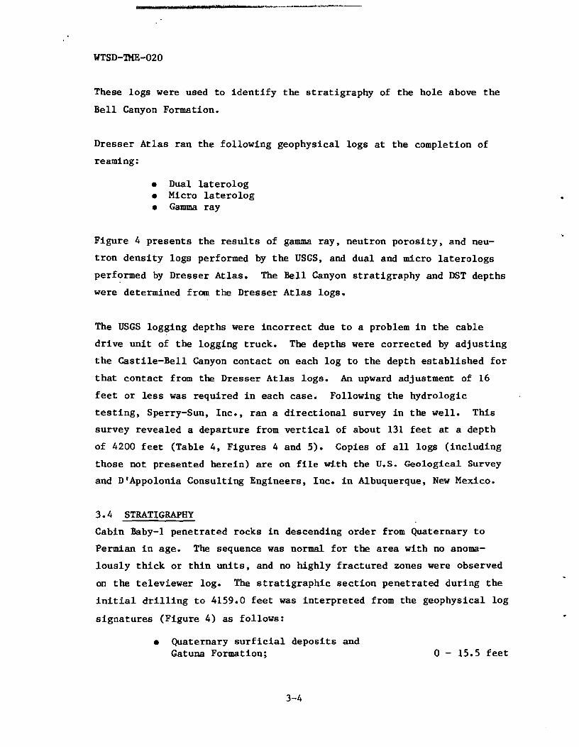
Dresser At las ran the following geophysical logs a t the completion of
reaming:
Dual l a t e ro log Micro l a t e r o l o g Gamma ray
Figure 4 presents the r e s u l t s of gamma ray, neutron poros i ty , and neu-
t ron densi ty logs performed by the USGS, and dual and micro l a t e ro logs
performed by Dresser Atlas. The B e l l Canyon s t ra t ig raphy and DST depths
were determined from the Dresser Atlas logs.
The USGS logging depths were incor rec t due t o a problem i n the cable
d r ive un i t of the logging truck. The depths were corrected by ad jus t ing
t h e Casti le-Bell Canyon contact on each log t o the depth es tab l i shed f o r
t h a t contact from the Dresser Atlas logs. An upward adjustment of 16
f e e t o r less was required i n each case. Following the hydrologic
t e s t i n g , Sperry-Sun, Inc., ran a d i r e c t i o n a l survey i n the w e l l . This
survey revealed a departure from v e r t i c a l of about 131 f e e t a t a depth
of 4200 f e e t (Table 4, Figures 4 and 5). Copies of a l l logs ( inc luding
those not presented here in) a r e on f i l e with the U.S. Geological Survey
and D'Appolonia Consulting Engineers, Inc. i n Albuquerque, New Mexico.
3.4 STRATIGRAPHY
Cabin Baby-1 penetrated rocks i n descending order from Quaternary t o
Permian i n age. The sequence was normal f o r the area with no anoma-
lous ly t h i c k o r t h i n u n i t s , and no highly f rac tu red zones were observed
on the televiewer log. The s t r a t i g r a p h i c sec t ion penetrated during the
i n i t i a l d r i l l i n g t o 4159.0 f e e t was in te rp re ted from the geophysical log
s igna tu res (Figure 4) a s follows:
Quaternary s u r f i c i a l deposi ts and Gatuna Formation; 0 - 15.5 f e e t

Tr iass ic Santa Rosa Formatiop; . 15.5 - 142.8 f e e t
Permian Dewey Lake Redbeds; 142.8 - 362.9 f e e t
Permian Rustler Formation; 362.9 - 653.0 f e e t
Permian Salado Formation; 653.0 7 2703.5 f e e t
Permian Cas t i l e Formation; 2703.5 - 4045.0 f e e t
Permian Bell Canyon Formation; 4045.0 - TD
St ra t ig raph ic information, including key marker beds fo r these forma-
t i o n s , i s summarized i n Table 2 and presented graphical ly i n Figure 4.
Because the hole is cased above 660 f e e t , the locations of geologic
contacts and marker beds above t h i s depth a re uncertain.
When Cabin Baby-1 was o r i g i n a l l y d r i l l e d i n 1974 and 1975, 114.0 f e e t of
t h e Bel l Canyon Formation was penetrated. The i n i t i a l d r i l l i n g was ter-
minated i n the Olds sandstone member of the B e l l Canyon Formation. The
deepening (4159.0 t o 4298.6 f e e t ) extended the borehole through the Olds
sandstone i n t o the Hays sandstone member. The s t ra t ig raph ic sect ion of
t h e Permian Bell Canyon Formation penetrated i n the i n i t i a l d r i l l i n g and
deepening, in terpre ted from the geophysical log signatures, includes the
following informal members:
Lamar limestone Ramsey sandstone Ford shale
. Olds sandstone Hays sandstone
4045.0 - 4086.0 f e e t 4086.0 - 4132.0 f e e t 4132.0 - 4140.0 f e e t 4140.0 - 4171.0 f e e t
4171.0 - TD
The Permian Bell Canyon Formation contains shales , calcareous and a rg i l -
laceous s i l t s t o n e s , s i l t y fine-grained sandstones, and limestones.
These c l a s t i c sediments were l a i d down as basin sediments a t about the
same time a s the Capitan reef (Capitan Limestone) was forming, when
basin subsidence was lessening (Powers e t a l . , 1978).

The Lamar limestone, Ramsey sandstone, and Ford shale were cored a t
ERDA-10 (SNL and USGS, 1983). Only the Ramsey sandstone, a very fine-
grained s i l t y sandstone and s i l t s t o n e , was c l ea r l y d is t inguishable i n
core. The Lamar limestone member, i den t i f i ed by the geophysical logs ,
consisted of interbedded limestone, calcareous s i l t s t o n e , and calcareous
shale. The Ford shale occurred within a very f i n e grained sandstone
uni t containing chips of grayish-black shale.
Dr i l lho le AEC-7 (SNL and DIAppolonia, 1982) penetrated with rock coring
the Lamar limestone, Ramsey sandstone, Ford shale , and Olds sandstone.
A t AEC-7 the Lamar limestone and Ramsey sand were described s imi la r ly a s
a t ERDA-10 (SNL and USGS, 1983). The Ford shale consisted of a l i g h t
olive-gray, calcareous, sandy s i l t s t one . The Olds sandstone at AEC-7
was described a s a l i gh t t o medium-gray, very f i ne grained, calcareous
sandstone with calcareous s i l t s t o n e and a t r ace of s i l t y limestone.
A t Cabin Baby-1, the top of the Olds sandstone is a t a depth of 4140.0
f e e t (below ke l l y bushing). When Cabin Baby-1 was i n i t i a l l y d r i l l e d ,
19.0 f e e t of the Olds sandstone were penetrated. Thus, no core descrip-
t i o n of t h i s por t ion of the Olds sandstone is available.
That por t ion of the Olds sandstone penetrated during deepening of Cabin
Baby-1 (4159.0 t o 4171.0 f e e t ) cons i s t s of medium-gray t o medium-dark-
gray, calcareous, carbonaceous s i l t s t o n e with very f i ne sand and black,
shaley par t ings and laminae. The Hays sandstone is l i t h o l o g i c a l l y very
s im i l a r , but is generally medium gray and contains more prominent black,
shaley or carbonaceous bands (0.01 t o 0.03 f ee t th ick) and zones of
black, shaley o r carbonaceous laminae (0.01 t o 0.03 f ee t th ick) . Also,
i t i s l e s s calcareous then t he Olds, based on a slower react ion t o a 10%
HC1 solut ion. Table 3 presents a de ta i l ed l i t h o l o g i c descr ip t ion of the
cored por t ion of Cabin Baby-1.

4.0 H Y D R O L O G I C TESTING
The hydrologic t e s t i n g program f o r the Cabin Baby-1 well was developed
through consultat ion between the DOE, USGS, DtAppolonia, Westinghouse,
and SNL. Upon completion of the deepening and logging of the hole, the
ava i l ab le s t r a t i g r a p h i c data were presented t o the New Mexico Environ-
mental Evaluation Group (EEG; S ta te review group f o r the WIPP pro jec t ) ,
and the proposed B e l l Canyon t e s t i n g program (methods t o be used, u n i t s
t o be t e s ted , e tc . ) was outl ined f o r the EEGts information and t o
s o l i c i t t h e i r comments. Testing the Salado Formation was added t o the
program a t a l a t e r date.
4.1 PURPOSES OF TESTING
Various breach consequence scenarios have been hypothesized f o r the WIPP
which involve interconnection of the WIPP with overlying and/or under-
l y i n g aquifers through one o r more boreholes. As the nearest water-
bearing un i t /aquif e r underlying the WIPP disposal horizon, the Bel l
Canyon Formation is of concern ( i n the case of a f a c i l i t y breach) as
e i t h e r a source of water which could flow through the WIPP and i n t o
o the r flow systems such a s the Rustler Formation, o r a s a s ink and means
of t ranspor t f o r f l u i d s which have become contaminated by passage
through the WIPP. To evaluate these concerns, three primary questions
must be addressed:
a What is the head po ten t i a l within the Bell Canyon Formation; i.e., w i l l the Bell Canyon serve as a source o r a s ink?
a What a re the hydraulic proper t ies of the B e l l Canyon; i.e., what is the capacity of the formation t o produce o r accept f l u i d ?
What a r e the physical/chemical propert ies of the Bell Canyon f l u i d s ; most importantly, what is the f l u i d densi ty?
Data relevant t o these questions had been collected a t boreholes AEC-7
(SNL and DtAppolonia, 1982), AEC-8 (SNL and D'Appolonia, 1983), and

ERDA-10 (SNL and USGS, 1983). Because of the d i f f i c u l t i e s inherent i n
t e s t i n g deep aqu i fe r s with low t r a n s m i s s i v i t i e s , ambiguit ies remain,
p a r t i c u l a r l y with regard t o t h e f l u i d densi ty and head p o t e n t i a l i n t h e
B e l l Canyon. The object ives of t h e Cabin Baby t e s t i n g program,
the re fo re , were t o provide b e t t e r da ta on the B e l l Canyon f l u i d dens i ty
and head p o t e n t i a l , and t o provide add i t iona l da ta on the permeabi l i t ies
of the water-bearing u n i t s wi th in the B e l l Canyon.
4.2 TEST INTERVAL SELECTION
Upon completion of t h e deepening and logging of the hole, the geologic
and geophysical da ta were evaluated t o s e l e c t the i n t e r v a l s i n the B e l l
Canyon Formation t o be tes ted . Five s t r a t i g r a p h i c members i n the B e l l
Canyon were i d e n t i f i e d :
Lamar limestone 4045.0 - 4086.0 f e e t Ramsey sandstone 4086.0 - 4132.0 f e e t Ford shale 4132.0 - 4140.0 f e e t Olds sandstone 4140.0 - 4171.0 f e e t Hays sandstone 4171.0 - TD
Through consul ta t ion between the DOE, SNL, USGS, D'Appolonia, and
Westinghouse, the decision was made t o test a l l of t h e Bel l Canyon
members except f o r the Ford shale. The Ramsey, Olds, and Hays sand-
s tones were se lec ted f o r t e s t i n g 'because they a r e the most porous
members of the upper B e l l Canyon. The Lamar limestone was se lec ted
because it had been t e s t e d previously at AEC-7 (SNL and D'Appolonia,
1982), AEC-8 (SNL and D'Appolonia, 1983), and ERDA-10 (SNL and USGS,
1983). Geophysical log s ignatures indicated t h e presence of r e l a t i v e l y
f i n e r grained mate r i a l s a t the member boundaries, thus these zones were
s e l e c t e d as packer "seats", with the balance of the u n i t s t o be
t e s ted . This plan m e t with t h e agreement of the EEG.
Following t h e completion of the Bel l Canyon tests, t h e decis ion was made
t o s t r a d d l e the e n t i r e Salado Formation plus the Salado-Castile contact
t o see how much, i f any, f l u i d would be produced. A production-
i n j e c t i o n packer (PIP) was set a t 2725.4 f e e t below KB 22, f e e t below

the top of the Cas t i l e Formation i n Anhydrite 111, t o i s o l a t e the Salado
from the formations below. The upper packer seat was selected a t the
highest e levat ion possible i n the Salado where the hole diameter was
small enough f o r the packer t o be able t o seat . This location proved t o
be from 760.8 t o 765.0 f e e t below KB, above Marker Bed 101.
4.3 TEST METHODS
D r i l l - s t e m t e s t s (DST) and rising-head "slug" t e s t s were selected as the
most appropriate means of quantifying the hydraulic propert ies of the
B e l l Canyon Formation. These t e s t s require a packer assembly mounted a t
the bottom of a tubing s t r i n g i n the hole which i s o l a t e s the in terval t o
be tes ted . For a test of the lower port ion of a hole, a s ingle packer
is used. To test a d i sc re te zone i n a hole, a s t raddle packer arrange-
ment is required. Other necessary equipment includes a shut-in too l
operated by a J-slot too l , which i n f l a t e s and de f la tes the packer(s) and
opens and closes the t e s t i n t e r v a l from the tubing, transducers reading
pressures above, below, and between the packers, and a data acquis i t ion
system (see Figures 6 and 7). Instrumentation speci f ica t ions w i l l be
discussed below.
The f i r s t s t e p i n a DST is t o s e l e c t the i n t e r v a l to be tested. The
packer separat ion is then adjusted t o correspond t o the in te rva l thick-
ness. Next, the packer assembly is run i n t o the hole t o the desired
depth, and the packers a re i n f l a t e d with the test i n t e r v a l shut-in
(closed o f f ) from the tubing above. The f l u i d i n the tubing is swabbed
out while the pressure i n the test i n t e r v a l s t ab i l i zes .
The ac tua l DST begins with opening the shut-in too l , which allows the
water i n the s t raddled i n t e r v a l t o en te r the tubing. Due to the large
pressure d i f f e r e n t i a l between the tubing and the straddled in te rva l ,
water under the i n i t i a l s t a t i c formation pressure flows rapidly towards
t h e borehole and up the tubing s t r ing . This is the f i r s t flow period
(FF'L). This period begins with a drop i n pressure from s t a t i c (shut-in
t o o l closed) t o a pressure corresponding t o the weight of the water

remaining i n the tubing ( a f t e r swabbing) above the transducer. As water
rises up the tubing s t r i n g , the pressure exer ted downward on the s t rad-
dled i n t e r v a l increases , reducing the pressure d i f f e r e n t i a l and thus ,
t h e flow ra te .
When t h e flow r a t e has decreased by about t e n t o twenty percent , t he
shut-in t o o l is c losed, s topping the flow of water up the tubing. This
i s the beginning of the f i r s t pressure buildup period (FBU). The for-
mation is allowed t o recover i n the f i r s t pressure buildup period f o r
about t h r e e t i m e s a s long as the f i r s t flow period, o r longer i f neces-
sa ry t o achieve a s t a b l e pressure. The shut-in t o o l is then reopened t o
i n i t i a t e t h e second flow period (SFL). The water l e v e l i n the tubing
w i l l not have changed s ince the end of the f i r s t flow period. The
second flow period t y p i c a l l y l a s t s seve ra l times as long a s the f i r s t
flow period, again u n t i l t he flow r a t e decreases by t e n t o twenty per-
cent . Again, the shut-in t o o l is closed and the second buildup period
(SBU) begins. This buildup period continues f o r a period not l e s s than
t h r e e t i m e s the second flow period, and longer i f necessary t o achieve a
s t a b l e pressure. These four per iods , FFL, FBU, SFL, and SBU, genera l ly
c o n s t i t u t e a s i n g l e complete DST.
During the second buildup period of the DST, t h e f l u i d is swabbed out of
the tubing so that a long-term s l u g t e s t can be performed. When t h e
pressure has s t a b i l i z e d during the SBU, the shut-in t o o l is opened. A s
with the f i r s t flow period ( F a ) of the DST, the pressure on t h e t rans-
ducer i n i t i a l l y drops from s t a t i c r e se rvo i r pressure t o a pressure cor-
responding t o the weight of the remaining f l u i d i n the tubing above t h e
transducer. As water rises up the tubing s t r i n g , the pressure on the
transducer rises. The s lug test c o n s i s t s of monitoring the pressure
rise. I d e a l l y , t h e pressure r i s e should be monitored u n t i l e ighty t o
n ine ty percent of the pressure l o s t is recovered, but f o r t y percent
recovery is genera l ly adequate t o def ine t h e shape of the recovery
curve, p a r t i c u l a r l y i f log-log p l o t t i n g techniques a r e used (Ramey e t
a l . , 1975).

Pressures above and below the t e s t ed i n t e r v a l a r e monitored during a l l
t e s t s so t h a t any leakage around the packers or other types of flow i n t o
the test i n t e r v a l from above o r below can be detected. Slow, uniform
pressure decreases of a few p s i above and below the test in te rva l a re
not uncommon, a s borehole f l u i d s may seep i n t o the adjacent for-
mations. Abrupt, higher magnitude pressure changes may indica te faul ty
packer s e a t s or o ther malfunctions.
4.4 INSTRUMENTATION
A l l instrumentat ion f o r the dri l l -s tem t e s t i n g was supplied by Lynes,
Inc.., of Houston, Texas. The down-hole equipment consisted of a Lynes
i n f l a t a b l e dri l l -s tem t e s t t o o l , a t r i p l e transducer which measured
pressure and temperature above, below, and between the packers, and a
t r i p l e conductor wire l ine (TCWL) from the transducers t o the data acqui-
s i t i o n system a t the surface (Figure 6). The data acquis i t ion system
consisted of a Lynes SC-2 i n t e r f a c e un i t between the transducer and a
HP-5316A frequency counter, a HP-59306A re lay ac tuator , a HP-85A com-
pu te r with tape dr ive f o r data recording, an Epson MX-80 p r i n t e r fo r a
real-time l i s t i n g of the da ta , and a HP-9872B p l o t t e r fo r a real-time
p l o t of the data (Figure 7). The same computer, p r i n t e r , and p l o t t e r
system w a s a l s o used f o r da ta reduction and analysis .
For the test on the Salado Formation, a Lynes re se t t ab le production-
i n j e c t i o n packer (PIP) was used t o i s o l a t e the Salado from lower forma-
t ions . The Lynes dri l l -s tem test too l with a s ing le packer was s e t a t
the top of the Salado. A Lynes Dig i t a l Memory Recorder (DMR) 312 was
suspended below the PIP t o provide a record of the pressure and tempera-
t u r e i n the bottom of the hole during the Salado t e s t . Following the
completion of the test and r e t r i e v a l of the PIP and DEIR, the bottom-hole
da ta were read out of the DMR using a Dig i t a l Surface Recorder (DSR)
300

4.5 TEST DATA ANALYSIS METHODS
The analyses of the DST data were t o produce answers t o the following
quest ions:
What a r e the hydraulic p roper t i e s of the t e s t e d un i t s?
What a r e the s t a t i c formation pressures i n t h e t e s t e d un i t s?
The a n a l y t i c a l methods used t o answer these quest ions a r e discussed
below.
4.5.1 Flow Period Data Analysis
The flow period data and s lug tests were analyzed by a method f i r s t
presented by Cooper et a l . (1967), and adapted t o DST's by Ramey et a l .
(1975). The method is used f o r ca lcu la t ing t h e t r ansmiss iv i ty of a
homogeneous, i s o t r o p i c confined rese rvo i r of uniform thickness which i s
f u l l y penetrated by a well. To i n i t i a t e a flow period, a hydraulic
gradient is es tab l i shed around the w e l l by swabbing the f l u i d from t h e
tubing with the test i n t e r v a l shut-in, and then opening t h e test
i n t e r v a l t o the tubing. The problem is described mathematically by:
where :
h = hydraulic head a t radius r, and t i m e t.
r = radius from wel l cen te r
t = t i m e
S = formation s t o r a t i v i t y
T = formation t r ansmiss iv i ty
This equation describes nonsteady, r a d i a l flow of groundwater.
The s o l u t i o n t o t h i s equation u t i l i z e d f o r ana lys i s of flow-period da ta
i s presented i n the form of curves of [H/Ho] and [(H,-H)/H~] versus the

dimensionless time parameter 8 = ~ t l r , ~ f o r each of s eve ra l values of a
= rs2s/rC2 where:
Ho = i n i t i a l (maximum) pressure d i f f e r e n t i a l (drawdown)
H = pressure d i f f e r e n t i a l a t time t
t = time elapsed s ince t e s t began
rs = rad ius of borehole
rc = i n s i d e rad ius of tubing s t r i n g
The use of these type curves is similar t o the Theis graphica l method of
pumping test analys is . P l o t s of t he q u a n t i t i e s [H/Ho] and [(Ho-H)/Ho]
versus t a re made on semi-log and log-log paper, respec t ive ly , of the
same s c a l e as the type curves. Semi-log p l o t t i n g and type curves a r e
bes t used when a minimum of about seventy percent recovery has
occurred. For l e s s e r degrees of recovery, log-log p l o t t i n g techniques
provide a more d e f i n i t i v e type-curve f i t (Ramey e t al., 1975). The type
curves a r e then placed over the test da ta and t r ans l a t ed hor izonta l ly
(wi th the hor izonta l axes co inc ident ) u n t i l a best f i t is achieved. I n
t h i s pos i t i on a match point is chosen, and the corresponding values of a
and 8 a r e read from the type curve, and t is read from the da ta p lo t .
The t r ansmiss iv i ty (T) is then ca lcula ted from the following rearrange-
ment of the equat ion presented above using the coordinates of the match
po in t :
The hydraul ic conduct iv i ty , K, can be ca lcula ted by d iv id ing the trans-
mis s iv i ty by the th ickness of the t e s t e d i n t e r v a l , b, or K = T/b. The
permeabi l i ty , k, may then be ca lcula ted from the following r e l a t ion :
IJ k = K - (Freeze and Cherry, 1979) P
where :
M = v i s c o s i t y
p = d e n s i t y

4.5.2 7 The buildup period data were analyzed using a method developed by Horner
(1951). Horner's method i s appl icable t o the buildup (recovery) of a
w e l l which f u l l y penet ra tes a homogeneous, i s o t r o p i c , hor izon ta l , i n f i -
n i t e , confined rese rvo i r following a constant-rate flow period.
Horner ' s so lu t ion is :
where :
p ( t ) = pressure a t t i m e t , p s i
ps = s t a t i c formation pressure, p s i
k = permeability, md
q = production r a t e of previous flow period, BPD
B = formation volume f a c t o r (=1.0 f o r single-phase
water r ese rvo i r )
p = f l u i d v i scos i ty , cp
h = thickness of formation t e s ted , f t
t(f1ow) = t i m e of previous flow period
d t = time elapsed s ince end of flow period
This equation is solved graphical ly by p l o t t i n g p ( t ) versus log t(f1ow) + d t
d t , drawing the appropr ia te s t r a i g h t l i n e through the da ta ,
and measuring the change i n p ( t ) on t h i s l i n e over one log cycle (m).
The above equation then reduces t o :
The semi-log p lo t used i n t h e Horner ana lys i s can a l s o be used t o esti- - -
t(f1ow) + d t mate the s t a t i c formation pressure. The a x i s where log
d t represents i n f i n i t e recovery t i m e , and the ext rapola t ion of the pressure
d a t a t o t h a t a x i s should equal the s t a t i c formation pressure.

4.6 TEST RESULTS
Tes t ing began on September 4, 1983 and ended on September 23, 1983. A
summary of the t e s t s performed is provided i n Table 5. The r e s u l t s of
t h e t e s t s a r e summarized i n Table 6, and discussed below. The FFL ana-
ly ses a r e not presented because f i r s t flows a r e t y p i c a l l y dominated by
d r i l l i n g f l u i d unloading, and serve primari ly t o help clean the hole f o r
t he more important SF'L. Flow t e s t s and s lug t e s t s a r e s imi l a r , repe t i -
t i v e t e s t s . The q u a l i t y of the da ta should increase with each succes-
s i v e t e s t , a s t he e f f e c t s of loading the formation with d r i l l i n g f l u i d
a r e progress ive ly lessened. For t h i s reason, and because s lug t e s t s a re
performed u n t i l a g r e a t e r degree of recovery is achieved than during
f low t e s t s , t he s lug t e s t s provide the r e s u l t s most representa t ive of
a c t u a l r e se rvo i r p rope r t i e s of a l l the flow t e s t s . Of the buildup
per iod analyses , the SBU r e s u l t s a r e regarded a s the more r e l i a b l e
because the S n ' s b e t t e r meet t he t h e o r e t i c a l assumptions of the analy-
sis technique than t h e FFLts, and because t h e SBU's were continued u n t i l
a g r e a t e r degree of recovery was obtained than during the FBUts.
4.6.1 DST-4178: Hays Sandstone
The Hays sandstone was t e s t e d between the depths 4178.0 and 4298.6 f e e t
below KB. Two flow t e s t s (DST-41781FF~ and SF'L), two buildup t e s t s (FBU
and SBU), and one s lug t e s t (SLUG) were performed (Figure 8). As shown
i n Table 6 and Figures 9 and 10, the analyses of the f i r s t and second
bui ldups provided permeabil i ty es t imates of 0.57 d and 0.71 md, respec-
t i v e l y . These correspond t o hydraul ic conduct ivi ty values of 1.3 x loa3 f t l d a y and 1.7 x f t l d a y , respec t ive ly . The flow-period pernea-
b i l i t y estimates are s l i g h t l y higher , wi th the second-flow data y i e ld ing
a value of 1.7 md (Figure 11) and the s lug- tes t da ta y ie ld ing a value of
0.94 md (Figure 12). These values correspond t o hydraul ic conduct ivi ty
estimates of 3.9 x f t l d a y and 2.2 x f t l d a y , respect ively.
The Horner p l o t of DST-4178lFBU (Figure 9) shows an early-time dev ia t ion
below t h e Horner s t r a i g h t l i n e , represent ing a s l i g h t pos i t i ve sk in ,
perhaps a mudcake, on the borehole wall . A similar e f f e c t was apparent

i n early-time data from DST-4178/SBU not shown i n Figure 10. When t h e
FBU d a t a a r e ex t rapo la t ed t o i n f i n i t e recovery time, they y i e l d a s t a t i c
formation pressure (pext) of 1883 ps ig (Figure 9). The very late- t ime
SBU da ta show a s l i g h t dev ia t ion above the Horner s t r a i g h t l i n e , proba-
bly r e f l e c t i n g the f a c t t h a t t he SFL was i n i t i a t e d before complete
recovery from the FFL was achieved. This upward-deviation phenomenon
r e f l e c t s a superpos i t ion of bui ldups from sepa ra te f l w events , and is
t y p i c a l l y d i s t ingu i shab le only when the buildup from the most recent
flow becomes of very small magnitude. When t h e l a t e s t SBU data a r e
ex t rapo la t ed t o i n f i n i t e time, they provide a s t a t i c formation pressure
e s t ima te of 1880 ps ig (Figure 10). With the t ransducer a t a depth of
4165.4 f e e t below KB, and a f l u i d pressure gradient of 0.485 p s i / f t (SG
= 1.12; Table 7) , t hese s t a t i c formation pressure es t imates correspond
t o a s t a t i c f l u i d l e v e l ( i n an open borehole) 283 t o 289 f e e t below KB,
which is about the l e v e l of t h e Dewey Lake Redbeds.
4.6.2 DST-4138: Olds Sandstone
The Olds sandstone was t e s t e d between t h e depths 4138.5 and 4170.9 f e e t
below KB. Two flow t e s t s (DST-4138/FFL and SFL), two buildup t e s t s (FBU
and SBU), and one s lug t e s t (SLUG) were performed (Figure 13). The
permeabi l i ty values derived from the f i r s t and second buildups a r e 2.2 x
md (Figure 14) and 3.5 x 10'~ md (Figure 15) , respect ive ly . These
correspond t o hydraul ic conduct iv i ty e s t ima tes of 4.5 x 10 '~ f t / d a y and
7.2 x f t / day , respect ive ly . The flow-period permeabil i ty e s t ima tes
a r e s l i g h t l y h igher , being 6.7 x nd f o r the second flow (Figure 16)
and 8.2 x md f o r the s l u g t e s t (Figure 17). These values corre-
spond t o hydraul ic conduct iv i ty estimates of 1.4 x f t / d a y and 1.7 x
f t / d a y , respect ive ly .
The Horner p l o t s of DST-4138/FBU (Figure 14) and SBU (Figure 15) both
show the very l a t e time da ta dev ia t ing below t h e Horner s t r a i g h t l i n e .
Such dev ia t ions a r e t y p i c a l l y the r e s u l t of some type of negat ive reser -
v o i r boundary, such a s a decrease i n permeabi l i ty a t some d i s t a n c e from
t h e well . The devia t ions could a l s o represent dep le t ion of a f i n i t e
r e s e r v o i r . Ext rapola t ing t h e FBU and SBU very l a t e time da ta t o

i n f i n i t e time. provides s t a t i c formation pressure est imates of 1934 ps ig
(F igure 14) and 1910 ps ig (Figure 15) , respect ively. With ' the trans-
ducer a t a depth of 4125.9 f e e t below KB, and a f l u i d pressure gradient
of 0.503 p s i / f t (SG = 1.16; Table 7 ) , these pressures correspond t o
s t a t i c f l u i d l e v e l s ( i n an open borehole) 281 f e e t and 329 f e e t below
KBy r e spec t ive ly , which a r e i n the middle of the Dewey Lake Redbeds.
4.6.3 DST-4100: Ramsey Sandstone
The Ramsey sandstone was t e s t e d between the depths 4100.5 and 4132.9
f e e t below KB. Two flow tests (DsT-~~OO/FFL and SFL), two buildup t e s t s
(FBU and SBU) and one s lug t e s t (SLUG) were performed (Figure 18). The
f i r s t and second buildups provided permeabil i ty est imates of 2.3 x 10'~
md (Figure 19) and 2.9 x md (Figure 20) , respect ively. These
values correspond t o hydraul ic conduct ivi ty est imates of 4.7 x
f t / d a y and 6.0 x f t / d a y , respec t ive ly . Again, the flow-period
permeabil i ty es t imates a r e s l i g h t l y higher , being 8.2 x md f o r t h e
second flow (Figure 21), and 8.7 x md f o r the s lug t e s t (Figure
22). These values correspond t o hydraul ic conduct ivi ty est imates of 1.7
x f t / d a y and 1.8 x f t / d a y , respectively..
The Horner p l o t s of DST-4100/FBU (Figure 19) and SBU (Figure 20) both
show a very l a t e time devia t ion of the da ta below the Horner s t r a i g h t
l i n e similar t o that observed i n DST-4138lFBU and SBU (Figures 14 and
15). Again, t h e devia t ions probably represent some type of negative
r e se rvo i r boundary. Ext rapola t ing the FBU and SBU very l a t e time da ta
t o i n f i n i t e t i m e provides s t a t i c formation pressure es t imates of 1916
p s i g (Figure 19) and 1892 ps ig (Figure 20), respect ively. With t h e
t ransducer a t a depth of 4087.9 f e e t below KB, and assuming a f l u i d
pressure gradient s i m i l a r t o that of the Olds sandstone f l u i d (0.503
p s i / f t ) , these pressures correspond t o s t a t i c f l u i d l e v e l s ( i n an open
borehole) 279 f e e t and 326 f e e t below KB, respect ively. These l e v e l s
a r e v i r t u a l l y i d e n t i c a l t o those ca lcula ted f o r the Olds sandstone
f l u i d .

4.6.4 DST-4044: Lamar Limestone
The Lamar limestone was t e s ted between the depths 4044.2 and 4097.4 f e e t
below KB. Because of the extremely l o w magnitude response of the u n i t ,
only a s ing le flow (FFL) and buildup (FBU) cycle was performed (Figure
23). As shown on Figure 24, the buildup response i n the Lamar was slow
and prolonged. The permeability estimated from the buildup data is 6 x
md (0.6 pd) (Figure 25). This corresponds t o a hydraulic conduc-
t i v i t y of 1 x f t /day . Permeabi l i t ies of t h i s order cannot be
determined precise ly with DST techniques, and thus, these values should
be regarded as order-of -magnitude estimates.
The expanded-scale Horner p lo t of DST-4044/FBU (Figure 25) shows t h e
d a t a devia t ing below the Horner s t r a i g h t l i n e a t extremely l a t e time,
probably i n response t o some type of negative rese rvo i r boundary. The
ex t rapo la t ion of these data t o i n f i n i t e time provides a s t a t i c formation
pressure es t imate fo r the Lamar of 1886 psig. With the transducer a t a
depth of 4031.6 f e e t below KB, and assuming a f l u i d pressure gradient
s imi la r t o that of the Olds sandstone f l u i d (0.503 p s i l f t ) , t h i s pres-
s u r e corresponds t o a s t a t i c f l u i d l e v e l ( i n an open borehole) 282 f e e t
below KB, v i r t u a l l y i d e n t i c a l t o that of the underlying sandstones.
4.6.5 DST-765 : Salado Formation
The Salado Formation was t e s ted between the depths 765.0 and 2725.4 f e e t
below KB. Two flow tests (DST-765/FFL and SFL), two buildup tests ( F ~ U
and SBU) , and one s lug test (SLUG) were performed (Figure 26). The
Salado did not respond s u f f i c i e n t l y during the FFL, FBU, and SFL t o pro-
v ide analyzable data. The SBU and s lug test were run f o r longer dura-
t i o n s t o provide b e t t e r data. The SBU was marked by a sudden 14 p s i
jump a f t e r about 280 minutes of recovery (Figure 27). The pressure jump
did not a l t e r the pressure t rend, but merely off set the trend by 14
ps i . The pressures recorded above and below the t e s ted i n t e r v a l showed
no f l u c t u a t i o n s a t the time of the pressure jump. The phenomenon was
not repeated, and its cause is unknown.

The expanded-scale Horner p lo t of DST-765lSBU (Figure 28) shows a
s t e a d i l y steepening curve. Using the slope of the l a t e s t data, the
permeability was calculated t o be about 9 x md, corresponding t o a
hydraulic conductivity of about 2 x f t lday. The slug test data do
not f i t a type curve very w e l l , probably due i n part t o the f a c t tha t
t h e pressure was s t i l l recovering from the previous flow t e s t s when the
s lug test was i n i t i a t e d . The best f i t obtained (Figure 29) provided a
value of permeability of 8 x md (80 nd). This value corresponds t o
a hydraulic conductivity of about 2 x f t lday. Neither of the above
test r e s u l t s should be considered anything other than order-of-magnitude
approximations. A t the conclusion of the slug test a f t e r about 25 hours
of flow, the Salado was producing about 0.005 gpm under a pressure
d i f f e r e n t i a l estimated t o be greater than 200 psi.
A s s t a t ed above, the Horner p lo t of DST-765lSBU (Figure 28) shows a
s t e a d i l y steepening curve. If the l a t e s t data a r e extrapolated t o i n f i -
n i t e t i m e , they provide a s t a t i c formation pressure estimate of about
390 psig. With the transducer a t a depth of 752.4 fee t below KB, and
assuming a f l u i d pressure gradient s imi la r t o tha t of NaC1-saturated
br ine (0.52 p s i l f t ; SG = 1.2), t h i s pressure corresponds t o a s t a t i c
f l u i d l e v e l ( i n an open borehole) about 2 f e e t below KB (or 6 f e e t above
the ground surface). The va l id i ty of the pressure extrapolat ion i s
quest ionable, and thus the s t a t i c f l u i d l eve l estimate is unreliable.
4.7 HYDROGEOCHEMICAL SAMPLING
One of the major object ives of the Cabin Baby t e s t i n g program was t o
obta in r e l i a b l e samples of the nat ive Bell Canyon Formation f lu ids .
These samples were t o provide information on the f l u i d propert ies
a f f e c t i n g flow, such as s p e c i f i c gravi ty ldensi ty and viscos i ty , a s w e l l
a s da ta on the major and minor element chemistries of the f lu ids .
Coring and conditioning boreholes, however, introduces foreign f l u i d s
i n t o the formations. To provide a means of d i f f e r e n t i a t i n g between
recent ly introduced f l u i d s and the nat ive formation f lu ids , an i n e r t
t r a c e r was added t o the d r i l l i n g f l u i d p r io r t o reaming and conditioning
the hole. The t r a c e r used was sodium thiocyanate (NaSCN), se lec ted
WTSD-TME-020
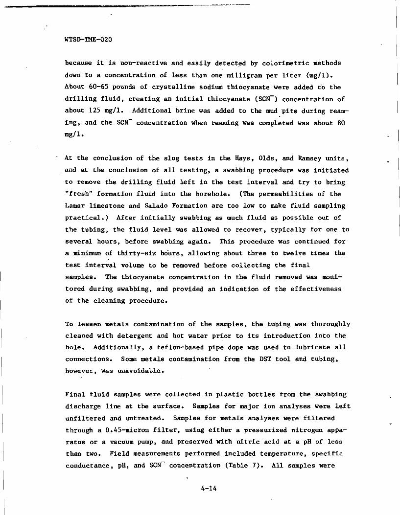
because it is non-reactive and e a s i l y detected by color imetr ic methods
down t o a concentrat ion of less than one milligram per l i t e r (mg/l).
About 60-65 pounds of c r y s t a l l i n e sodium thiocyanate were added t b the
d r i l l i n g f l u i d , crea t ing an i n i t i a l thiocyanate (SCN-) concentrat ion of
about 125 mg/l. Additional br ine was added t o the mud . p i t s during ream-
ing , and the SCN- concentrat ion when reaming was completed was about 80
mg/ 1.
- A t the conclusion of t h e s lug tests i n the Hays, Olds, and Ramsey u n i t s ,
and a t the conclusion of a l l t e s t i n g , a swabbing procedure was i n i t i a t e d
t o remove the d r i l l i n g f l u i d l e f t i n t h e test i n t e r v a l and t r y t o bring
"fresh" formation f l u i d i n t o the borehole. (The permeabi l i t ies of the
Lamar limestone and Salado Formation a r e too low t o make f l u i d sampling
p rac t i ca l . ) Af ter i n i t i a l l y swabbing as much f l u i d as poss ib le out of
t h e tubing, t h e f l u i d l e v e l was allowed t o recover, t y p i c a l l y f o r one t o
severa l hours, before swabbing again. This procedure was continued f o r
a minimum of th i r ty - s ix hdurs, allowing about three t o twelve times the
test i n t e r v a l volume t o be removed before c o l l e c t i n g the f i n a l
samples. The thiocyanate concentrat ion i n the f l u i d removed was moni-
tored during swabbing, and provided an ind ica t ion of the e f fec t iveness
of t h e cleaning procedure.
To l e s sen metals contamination of the samples, the tubing was thoroughly
cleaned with detergent and hot water p r i o r t o i ts in t roduct ion i n t o the
hole. Addit ionally, a teflon-based pipe dope was used t o l u b r i c a t e a l l
connections. Some metals contamination from the DST too l and tubing,
however, w a s unavoidable.
F i n a l f l u i d samples were co l l ec ted i n p l a s t i c b o t t l e s from the swabbing
discharge l i n e a t the surface. Samples f o r major ion analyses were l e f t
u n f i l t e r e d and untreated. Samples f o r metals analyses were f i l t e r e d
through a 0.45-micron f i l t e r , using e i t h e r a pressurized ni t rogen appa-
r a t u s o r a vacuum pump, and preserved with n i t r i c ac id a t a pH of l e s s
than two. Fie ld measurements performed included temperature, s p e c i f i c
conductance, pH, and SCN- concentrat ion (Table 7). A l l samples were

s to red i n a r e f r i g e r a t o r a t the s i t e p r i o r t o shipment t o D'Appolonia
Labora tor ies , Export, Pennsylvania, i n sealed i c e ches ts maintained a t
about 4OC. Preservat ion and shipment procedures were i n accordance with
recommendations of the U.S. EPA (1979) and APHA (1980).
4.7.1 Hays Sandstone Fluid Sampling
At the conclusion of DST-4178/SLUG, swabbing w a s begun t o t r y t o remove
a l l t r a c e s of d r i l l i n g f l u i d from the Hays sandstone t e s t i n t e rva l . A
t o t a l of 34 swabs were pul led over a period of about 35 hours. About
6400 ga l lons of f l u i d were removed, represent ing 12 times the volume of
t h e test i n t e r v a l . The thiocyanate (scN-) concentrat ion i n the f l u i d
was measured co lo r ime t r i ca l ly about every o the r swab. The SCN- concen-
t r a t i o n dropped from about 46 mg/l, measured a f t e r about 1.7 t e s t -
i n t e r v a l volumes were removed, t o about two mg/l i n the f i n a l sample
s e n t t o the labora tory , which was co l l ec t ed a f t e r about 12 t e s t - in t e rva l
volumes were removed (Table 7; Figure 30). The SCN- concentrat ion
appeared t o s t a b i l i z e between about one and two mg/l a f t e r about 9.5
t e s t - i n t e r v a l volumes had been removed. After 12 t e s t - in t e rva l volumes
had been removed and t h e SCN- concentrat ion had remained r e l a t i v e l y
s t a b l e , f l u i d samples were co l l ec t ed f o r labora tory ana lys is and
swabbing was discontinued.
The analyses of t h e Hays sandstone f l u i d samples a r e summarized i n Table
7. Based on t h e SCN- concentrat ion, the f l u i d samples appear t o be con-
taminated with about two percent d r i l l i n g f lu id . The Hays f l u i d i s a
sodium-calcium chlor ide brine, with a t o t a l dissolved s o l i d s (TDS)
concent ra t ion of about 191,000 mg/l. The f l u i d is neu t ra l , having a pH
of 7.0, and has a s p e c i f i c conductance of about 320,000 vmhos/cm. The
two p rope r t i e s most important from a hydraul ics s tandpoint a re s p e c i f i c
g r a v i t y and v i scos i ty . These parameters have values of 1.12 and 1.30
cp , respec t ive ly .
4.7.2 Olds Sandstone Fluid Sampling
Following DST-4138/SLUG, t h e Olds sandstone t e s t i n t e r v a l was cleaned by
swabbing. Due t o the low permeabil i ty and production r a t e of the Olds

sandstone, swabbing u n t i l the SCN- concentrat ion dropped t o one t o two
mg/l was not p rac t i ca l . Four swabs were pulled over a period of about
36 hours. The t o t a l f l u i d volume removed was about 550 gal lons , repre-
sen t ing about 3.7 t i m e s t he volume of the t e s t in te rva l . The f l u i d
sample co l l ec ted a t the end of the four th swab had a SCN- concentrat ion
of about 16 mg/l (Table 7 ) , ind ica t ing d r i l l i n g f l u i d contamination of
about twenty percent.
The Olds sandstone f l u i d is a sodium chlor ide br ine , with a pH of about
7.3, a TDS of about 263,000 mg/l, and a s p e c i f i c conductance of about
430,000 pmhos/cm (Table 7). Its s p e c i f i c gravi ty is about 1.16 and its
v i s c o s i t y is about 1.54 cp. Greater d r i l l i n g f l u i d contamination is
l i k e l y the cause, a t l e a s t i n p a r t , of the Olds samples' ion ic concen-
t r a t i o n s , s p e c i f i c g rav i ty , and v i s c o s i t y being g rea te r than those of
t h e Hays sandstone f l u i d .
4.7.3
Following DST-4100/SLUG, an attempt was made t o swab the Ramsey sand-
stone t e s t i n t e r v a l and c o l l e c t a f l u i d sample. A t the end of the t h i r d
swab, the swabbing cable parted and the swabbing assembly dropped
through the dry tubing, damaging the sea t nipple and b a l l bar s leeve on
t h e DST tool . When the b a l l bar s leeve was damaged, d r i l l i n g f l u i d i n
the borehole annulus above the test i n t e r v a l entered the tubing. A t
t h a t po in t , the e n t i r e DST assembly had t o be t r ipped out of the hole
and repaired.
The th ree swabs successful ly pulled produced a t o t a l of about 285
ga l lons , or about 1.8 t e s t - in te rva l volumes, over a period of about t e n
hours. The SCN- concentrat ion a t the end of the t h i r d swab was about 29
mg/l.
The hydraul ic p roper t i e s of t h e Ramsey sandstone are very s i m i l a r t o
those of the Olds sandstone (Table 6). Because of the d i f f i c u l t i e s
encountered i n t ry ing t o obta in a clean sample of the Olds sandstone
f l u i d , and because of the t i m e and expense required t o go back i n t o the

hole, r e s t radd le the Ramsey, and s t a r t swabbing a l l over again, the
decis ion was made t o abandon the Ramsey sampling attempt, and proceed
with the next DST.
4.7.4 Bell Canyon Fluid Sampling
After the f i n a l DST, a bridge plug (PIP) was s e t a t 4038.9 fee t below KB
a t the base of the Cas t i l e Formation i n Anhydrite I. The d r i l l tubing
was l e f t attached t o the PIP and open t o the in te rva l below, forming an
observation w e l l completed through tha t portion of the Bell Canyon
Formation penetrated by Cabin Baby-1 (Figure 3). Swabbing was i n i t i a t e d
t o remove the d r i l l i n g f l u i d from the hole, so tha t the f l u i d l eve l i n
t h e tubing would be an accurate representat ion of the hydraulic head of
the upper Bell Canyon. A sample was collected on the f i f t h swab f o r
s p e c i f i c gravi ty and viscos i ty determinations fo r the d r i l l i n g f l u i d
(Table 7). The SCN- concentration on the eleventh swab was about 26
mg/l. On the twelf th swab, the swabbing cable parted and the swabbing
assembly passed through thk PIP and went t o the bottom of the hole,
where i t remains. To tha t point , about 1800 gallons, representing about
1.5 times the v o l u n ~ of the t e s t i n t e r v a l , had been swabbed over a
period of about 16 hours.
The PIP and tubing were removed from the hole, repaired, and rese t a t
4040.8 f e e t below KB. Swabbing recommenced, and continued fo r about 38
hours. Ibenty-six swabs were pulled, producing a t o t a l of about 4450
gal lons , o r about 3.8 times the volume of the i so la ted portion of the
hole. The SCN- concentration was monitored c losely during swabbing, and
appeared t o s t a b i l i z e around two mg/l a f t e r the twenty-second swab. A
sample was col lec ted on the twenty-fourth swab fo r spec i f i c gravi ty and
v i scos i ty determinations, and a f u l l set of samples was collected on the
f i n a l swab fo r m j o r and minor element chemistry and f l u i d propert ies
determinations (Table 7).
The m j o r and minor element chemistries of the f i n a l sample are very
s imi la r t o those of the Hays sandstone f lu id sample (Table 7). This i s
t o be expected as the Hays sandstone i s the most permeable Bell Canyon
4-17

u n i t i n Cabin Baby-1, and must have been the source of the majori ty of
t h e f l u i d produced during swabbing. Based on the f i n a l SCN- concen-
t r a t i o n of about two t o four mg/l, the well is contaminated with l e s s
than f i v e percent d r i l l i n g f l u i d .
4.8 PRESENT WELL CONDITION
Af te r the Bell Canyon por t ion of Cabin Baby-1 was cleaned by swabbing, a
wellhead assembly was at tached t o t h e tubing a t the ground surface and
t h e hole was l e f t as an upper B e l l Canyon observation wel l (Figure 3).
The annulus around the tubing was f i l l e d with d r i l l i n g f l u i d t o the
surface. The f l u i d l e v e l i n the tubing w i l l be monitored by SNL and/or
USGS. As the lower por t ion of the wel l is s t i l l contaminated s l i g h t l y
by d r i l l i n g f l u i d , which has a higher s p e c i f i c g rav i ty than t h e
formation f l u i d s , the f l u i d l e v e l i n the tubing w i l l be s l i g h t l y lower
than i t would be with no contamination. On December 13, 1983, the f l u i d
l e v e l i n the tubing was about 310 f e e t below the ground surface .

REFERENCES
American Public Health Association, 1980, Standard Methods f o r the Examination of Water, 15th ed i t ion , APHA, Washington, D.C.
Cooper, H. H., J. D. Bredehoeft, and I. S. Papadopulos, 1967, "Response of a Finite-Diameter Well ' t o an Instaneous Charge of Water", Water Resources Research, V. 3, No. 1, pp. 263-269.
Freeze, R. A. and J. A. Cherry, 1979, Groundwater, Prentice-Hall, Inc., Englewood C l i f f s , N J , 604 pp.
Goddard, E. N., chm., e t a l . , 1948, Rock Color Chart, Washington, National Research Council ( repr in ted by Geological Society of America,
Grace, M. P., 1974a, "Application f o r Permit t o D r i l l , Deepen, or Plug Back," Form 9-331C, U.S. Department of the I n t e r i o r , Geological Survey.
Grace, M. P., 1974b, "Well Location and Acreage Dedication P la t , " Form C-102, New Mexico O i l Conservation Commission.
Grace, M. P., 1974c, "Sundry Notices and Reports on Wells," Form 9-331, U .S. Department of the I n t e r i o r , Geological Survey.
Grace, M. P., 1975, ' W e l l Completion o r Recompletion Report and Log," Form 9-330, U.S. Department of the I n t e r i o r , Geological Survey.
Horner , D. R., 1951, "Pressure Buildup i n Wells, " Proc. Third world Pet. Cong., The Hague, Sec. 11, pp. 503-523. Also Reprint Ser ies , No. 9- Pressure Analysis Methods, Soc. Pet. Engr., A m , Dallas, TX, 1967 PP*
Powers, D. W., S. J. Lambert, S. E. Shaffer , L. R. H i l l , and W e D. Weart, eds., 1978, Geological Characterizat ion Report, Waste I s o l a t i o n P i l o t Plant (WIPP) S i t e , Southeastern New Mexico, SAND78-1596, Vol. I
- -- and 11.
Ramey, H. J., R. G. Agarwal, and I. Martin, 1975, "Analysis of 'Slug Test ' o r DST Flow Period Data", Jour. Can. Pet. Tech., Vol. 14, No. 3 , pp. 37-47.
Sandia National Laboratories and D'Appolonia Consulting Engineers, 1982, Basic Data Report fo r Dr i l lhole AEC-7 (Waste I s o l a t i o n P i lo t Plant- WIPP), SAND79-0268, Sandia National Laboratories, Albuquerque, NM.
Sandia National Laboratories and D'Appolonia Consulting Engineers, 1983, Basic Data Report for Dr i l lho le AEC-8 (Waste b o l a t i o n - p i l o t Plant- WIPP), SAND79-0269, Sandia National Laboratories, Albuquerque, NM.

Sandia National Laboratories and U.S. Geological Survey, 1983, Basic Data Report for Drillhole ERDA 10 (Waste .Isolation Pilot Plant-WIPP), SAND79-0271, Sandia National Laboratories, Albuquerque, 1W.
U.S. Department of Energy, 1983, Summary of the Results of the Evalu- ation of the WIPP Site and Preliminary Design Validation Program, WIPP- DOE-161, USDOE, Albuquerque, NM.
U.S. Environmental Protection Agency, 1979, Methods for Chemical Analysis of Water and Wastes, EPA-6004-79-020, Office of Research and Development, USEPA, Cincinnati, Ohio.

TABLES

TABLE 1 ABRIDGED H I S T O R Y OF BOREHOLE CABIN BABY-1
Locat ion: Sec. 5 T23S R31E
1980.0 f e e t from the north l i n e
1980.0 f e e t from the e a s t l i n e '
Eddy County, New Mexico
Elevation: GL (ground l eve l ) 3320 (approximate e l eva t ion)
KB (ke l ly bushing) 3328 (1983)
Cabin Baby-1 was i n i t i a l l y d r i l l e d i n 1974 and 1975 as a wildcat hydro-
carbon well. Cabin Baby-1 was reentered i n 1983 t o deepen and perform
hydrologic t e s t i n g i n support of the s i t e charac ter iza t ion a c t i v i t i e s
f o r the WIPP. Datum f o r depth measurements given i n Tables 2, 3, and 4,
and Figures 4 and 5 i s the k e l l y bushing (8.0 f e e t from ground level ) .
F ie ld l i t h o l o g i c log prepared by: Dann Meyer (D'Appolonia Consulting Engineers, Inc.)
Geophysical logs recorded by: Dresser Atlas (1975, 1983)
United S ta tes Geological Survey (1983)
Hydrologic t e s t i n g equipment by: Lynes, Inc. (1983)
Mud ana lys i s : Marquez Trucking (1983)
Direc t ional survey by:
D r i l l i n g contractor:
Coring contractor:
Sperry-Sun, Inc. (1983)
Michael P. Grace (1974-1975)
Salazar Bros., Inc. (1983)
Christensen Diamond Products Co.

WTSD-TME-020
D r i l l i n g record:
Casing:
Mud :
TABLE 1 (continued)
commenced i n i t i a l d r i l l i n g May 31, 1974 and completed i n i t i a l d r i l l i n g February 7, 1975 at a depth of 4159.0 f e e t below KB. The 1983 r een t ry of Cabin Baby-1 commenced cor ing on August 17, 1983 and completed co r ing (deepening) on August 19, 1983 a t a t o t a l depth of 4298.6 f e e t below KB.
13-3/8" OD cas ing s e t and cemented from 650 f e e t t o su r face (1974).
Unknown (1974, 1975) 4159.0-4298.6 f e e t - br ine , salt g e l , chromate, c a u s t i c soda, s t a r c h , sodium th iocyanate t r a c e r (1983)
CORE BIT RECORD
CORE DEPTH FEET ROTATING MAKE - - SIZE - SIZE - OUT DRILLED HOURS
Chr is tensen Diamond 7-27/32" OD 4.0" 4298.6' 139.6 9.25
Products
REAMING RECORD
BIT BIT DEPTH FEET ROTATING MAKE SIZE OUT REAMED TIME - TYPE -
GH Texas Reamer 9-7/8" Tri-cone 4298.6 898.6 2 days not cont inuous
CORING SUMMARY
Drillers Depth Weight on Circ. Core I n t e r v a l B i t I n t e r v a l Pressure Feet Feet Percent
Core No. ( f e e t ) RPM (x 1000 lbs . ) (PSI) Cored Recovered Recovered

ROCK UNIT
TABLE 2 STRATIGRAPHIC SUMMARY OF BOREHOLE C A B I N BABY-1
Quaternary
T r i a s s i c
Santa Rosa Sandstone
Permian
Dewey Lake Redbeds
Rus t l e r Formation
Magenta Dolomite member
Culebra Dolomite member
Salado Formation
Upper member
MB 1 0 1 ( ~ )
MB 102
MB 103
MB 105
MB 106
MB 107
MB 108
MB 109
MB 111
MB 112
MB 113
MB 114
MB 115
MB 116
McNutt member
DEPTH INTERVAL IN FEET( ) (BELOW KELLY BUSHING)

TABLE 2 (Continued)
ROCK UNIT
MB 121
MB 122
Union Anhydrite
MB 123
MB 124
MB 126
Lower member
MB 127
MB 128
MB 129
MB 130
MB 131
MB 132
MB 133
MB 134
MB 135
MB 136
MB 137
MB 138
MB 139
MB 140
MB 141
MB 142
MB 143
MB 144
Cowden Anhydrite
Castile Formation
Anhydrite I11
Halite 11
Anhydrite I1
DEPTH INTERVAL IN FEET(~~~) (BELOW KELLY BUSHING)

TABLE 1 (continued)
ABRIDGED HISTORY OF BOREHOLE CABIN BABY-1
Dresser Atlas logs( ' )
Acoustilog Gamma Ray Micro Laterolog Laterolog
Dresser Atlas
4-Arm Caliper Gamma Ray Compensated Neutron
Single-Arm Caliper Compensated Neutron Gamm Ray
Dual Laterolog Micro La t erolog Gamma Ray
USGS L O ~ S ( ~ )
3-Arm Caliper Gamma Ray Neutron Density Neutron Porosity Acoustic Televiewer
Sperry-Sun, Inc. (2)
Direct ional Survey
Run Feet Logged Date No. From To
( ) ~ e ~ t h s measured from ground surf ace.
( 2 ) ~ e p t h s measured from ke l ly bushing.

TABLE 2 (Continued)
ROCK UNIT DEPTH INTERVAL IN FEET( ) (BELOW KELLY BUSHING)
Halite I
Anhydrite I
Bell Canyon Formation
Lamar limestone
Ramsey sandstone
Ford shale
Olds sandstone
Hays sandstone
4045.0 - 4086.0 4086.0 - 4132.0 4132.0 - 4140:o 4140.0 - 4171.0
4171.0 - 4298.6 (TD)
NOTE: Because the hole is cased above 660 feet, the location of geologic contacts and marker beds above this depth are uncertain.
FOOTNOTES:
(llDepth is base of unit when single number is given.
(2)~epths to unit picks were based on geophysical log signatures.
( 3 ) ~ ~ = Marker Bed

TABLE 3 LITHOLOGIC LOG OF DEEPENED PORTION OF C A B I N BABY-1
[Depths reported a r e measured from k e l l y bushing and a r e corrected t o
Dresser At las geophysical l og depths. Color designat ions a r e from the
Geological Society of America Rock Color Chart (Goddard et a l . , 1948).]
LITHOLOGIC DESCRIPTION DEPTH INTERVAL
( I N FEET)
S i l t s t o n e , medium-gray (N5) t o medium-dark-gray (N4); very f i n e grained sand, calcareous, carbonaceous; contains black ( N l ) , s ha l ey , discont inuous and continuous pa r t i ngs and laminae; mostly unbedded; laminae usua l ly a l igned horizon- t a l l y (i.e . , perpendicular t o core a x i s ) ; concentrat ion of black laminae and blebs from 4159.5 t o 4161.6 f e e t ; l a rge b leb , poss ib l e f o s s i l impr in t , carbonaceous at 4162.6 f e e t (similar form occurs s e v e r a l t i m e s i n core) ; f o s s i l i f e r o u s zone, s h e l l fragments, carbonaceous impr in ts from 4165.3 t o 4165.7 f e e t ; f o s s i l imprint ( s imi l a r t o 4162.6 f e e t ) a t ' 4166.3 f e e t ; concent ra t ion of carbonaceous part ings/ laminae and b lebs , mostly a l igned ho r i zon ta l ly with l a r g e f o s s i l impr in t ( s i m i l a r t o 4162.6 f e e t ) from 4166.9 t o 4171.1 f e e t ; p y r i t i z e d blebs at 4172.6 and 4173.6 f e e t ; f i n e , t h i n (<0.1 inch ) , discont inuous , carbonaceous laminae (probably depo- s i t i o n a l f e a t u r e , poss ib ly b io turba ted) from 4177.3 t o 4178.9 f e e t ; l a r g e laminated c l a s t i nc lus ion , gray s i l t s t o n e w i t h black laminae from 4179.8 t o 4179.9 f e e t ; black carbon- aceous laminae and f o s s i l s (decreasing downward) from 4179.9 . . . . . . . . . . . . . . . . . . . . . . . . . t o 4182.0 f e e t 4159.0 - 4182.0
S i l t s t o n e , medium-gray (N5) t o medium-dark-gray (N4); very f i n e grained sand, ca lcareous , l i t t l e t o no carbonaceous ma te r i a l ; s m a l l (-0.25 inch) c a l c i t e - f i l l e d vug a t 4190.2 f e e t ; discont inuous, black (Nl) shaley o r carbonaceous laminae (<0.1 inch) at 4197.6 f e e t ; concent ra t ions of carbonaceous blebs o r laminae from 4198.5 t o 4198.9 f e e t ; s h o r t , discont inuous, black, carbonaceous laminae, a l igned h o r i z o n t a l l y (i.e., perpendicular t o core a x i s ) a t 4199.4 f e e t ; concent ra t ion of black, s h o r t , discont inuous laminae w i t h smal l c l a s t (0.25 inch) of underlying s i l t s t o n e a t 4203.2 f e e t . . . . . . . . . . . . . . . . . . . . . . . . . . 4182.0 - 4203.2
S i l t s t o n e , medium-gray (N5) t o medium-light-gray (N6), cal- careous , unbedded, massive; without any carbonaceous o r sha l ey laminae; uniformly f i n e grained . . . . . . . . . . . . . 4203.2 - 4208.8

TABLE 3 (Continued)
LITHOLOGIC DESCRIPTION DEPTH INTERVAL
( I N FEET)
S i l t s t o n e , medium-gray (N5) t o medium-light-gray (N6), cal- careous , unbedded, massive; wi th continuous, b lack , sha ley o r carbonaceous laminae, and evenly disseminated, discon- t i nuous , s h o r t laminae from 4208.8 t o 4209.0 f e e t ; t h i c k , (up t o 0.75 inch) , b lack , non-horizontal, anastomosizing, continuous laminae o r band from 4208.8 t o 4213.9 f e e t ; b lack , discontinuous carbonaceous laminae (<0.1 inch ) , a t 4211.5 f e e t ; prominent zone of carbonaceous laminae from 4213.5 t o 4213.9 f e e t , discontinuous a t 4213.5 f e e t , and continuous, h o r i z o n t a l at 4213.6 f e e t ; decreasing concentra- t i o n of laminae from 4213.6 t o 4213.9 f e e t ; conta ins lami- na ted clast inc lus ion (>1.0 inch ) , poss ib ly from underlying u n i t . . . . . . . . . . . . . . . . . . . . . . . . . . . . . . 4 2 0 8 . 8 - 4 2 1 3 . 8
S i l t s t o n e , medium-gray (N5), f i n e gra ined , unbedded, massive, calcareous (slow r e a c t i o n wi th 10% HC1 s o l u t i o n ) , carbonaceous laminae; t i n y p y r i t e c r y s t a l s from 4215.6 t o 4215.7 f e e t ; zone of concent ra ted , black, carbonaceous laminae, w i th rounded inc lus ion of non-laminated s i l t s t o n e (from underlying u n i t ) from 4217.7 t o 4217.9 f e e t ; cont in- uous, b lack , sha ley or carbonaceous l a y e r (-0.02 f e e t t h i c k ) a t 4220.6 f e e t ; core f r ac tu red along lower contact of t h i s l a y e r a t 4220.6 f e e t ; l o s t core between 4217.9 and 4219.0 f e e t . . . . . . . . . . . . . . . . . . . . . . . . . . . . . , 4 2 1 3 . 8 - 4 2 2 0 . 6
S i l t s t o n e , medium-gray (N5), f i n e gra ined , unbedded, mas- s i v e , ca lcareous (slow reac t ion wi th 10% HC1 s o l u t i o n ) , w i th evenly disseminated, s h o r t , discontinuous sha ley o r car- bonaceous laminae, black, u sua l ly a l igned hor i zon ta l ly ; p o s s i b l e f o s s i l i f e r o u s zone ( s h e l l fragment) a t 4222.2 feet; zone of continuous b lack , shaley o r carbonaceous bands (up t o 0.5 i n c h t h i c k ) wi th many th inne r laminae from 4222.8 t o 4223.0 f e e t ; core breaks evenly along upper and lower con- t a c t s of banded zone; zone wi th sha ley o r carbonaceous b lebs from 4223.0 t o 4224.0 f e e t ; continuous sha ley or ' carbona- ceous bands, dark-gray (N3) t o black (Nl) , mostly t h i c k (0.02 f e e t ) bands wi th a few <0.1 inch laminae from 4224.8 t o 4224.9 f e e t ; core breaks evenly along upper contac t of . . . . . . . . . . . . . . . . . . . . . . . . t h i s banded zone 4220.6 - 4224.9
S i l t s t o n e , medium-gray (N4), f i n e gra ined , unbedded, mas- s i v e , ca lcareous (slow reac t ion wi th 10% HC1 s o l u t i o n ) ; black band (0.02 f e e t t h i c k ) , under la in by s i l t s t o n e , f i n e gra ined (without sand component) laminated wi th black sha ley o r carbonaceous m a t e r i a l , from 4227.77 t o 4227.84 f e e t ; i n t e n s e l y broken core from 4237.7 t o 4238.0 f e e t . . . . . . . . 4224.9 - 4238.0

TABLE 3 (Continued)
LITHOLOGIC DESCRIPTION DEPTH INTERVAL
( I N FEET)
S i l t s t o n e , medium-gray (N4), f i n e grained, unbedded, massive, calcareous (slow reac t ion with 10% HC1 so lu t ion ) , with shaley/carbonaceous laminae; zone of t h i n ((0.1 inch) black shaley/carbonaceous laminae from 4238.0 t o 4238.1 f e e t ; core breaks evenly along upper contact of t h i s l aye r ; zone of discontinuous, shaley/carbonaceous laminae and blebs (up t o 0.75 inch) , usua l ly or ien ted subhorizontal ly ( i .e., nea r ly perpendicular t o core a x i s ) from 4238.1 t o 4242.9 f e e t ; black, continuous band (0.01 f e e t ) , shaley o r carbon- aceous, containing many small (<lnnn) rounded inc lus ions of . . . . . . . gray s i l t s t o n e from underlying u n i t a t 4242.9 f e e t 4238.0 - 4242.9
S i l t s t o n e , medium-gray (N4), f i n e grained, unbedded, mas- s i v e , calcareous (slow reac t ion with 10% HC1 so lu t ion ) ; black band (0.1 f e e t t h i ck ) contains concentrat ion of black sha ley carboniferous laminae at 4243.8 f e e t ; core breaks evenly along upper contact of band at 4243.8 f e e t ; zone of . . . . . d i f f u s e black laminae from 4243.9 f e e t t o 4244.2 f e e t 4242.9 - 4250.9
S i l t s t o n e , medium-gray (N4), f i n e grained, unbedded, mas- s i v e , calcareous (slow reac t ion with 10% HC1 so lu t ion ) , with d ispersed shaley/carbonaceous mater ia l ; concentrat ion of d ispersed mater ia l is lower than i n comparable overlying u n i t s ; zone of concentrat ion of t h i n (0.2 t o (0.1 inch) continuous laminae of shaley/carbonaceous mater ia l from . . . . . . . . . . . . . . . . . . . . . 4254.2 t o 4254.3 f e e t 4250.8 - 4254.3
S i l t s t o n e , medium-gray (N4), f i n e grained, unbedded, mas- s i v e , calcareous (slow reac t ion with 10% HC1 so lu t ion ) . . . . . 4254.3 - 4266.0
S i l t s t o n e , medium-gray (N4), f i n e grained, unbedded, mas- s i v e , calcareous (slow reac t ion with 10% HC1 so lu t ion ) , with disseminated blebs and discontinuous laminae of black (N1 ) , shaley/carbonaceous mater ia l ; black, continuous bands (0.01 f e e t ) , wi th undulatory contac ts and va r i ab le thickness a t 4267.0 f e e t ; black, continuous band, shaley/carbonaceous ma te r i a l at 4268.3 f e e t . . . . . . . . . . . . . . . . . . . . 4266.0 - 4268.3
S i l t s tone , medium-gray (N5), sandy, may be s l i g h t l y clayey, ca lcareous , unbedded, massive; dark-gray (N3), continuous band (0.02 f e e t t h i c k ) , shaley/carbonaceous, with i r r e g u l a r upper contac t and even lower contact at 4270.0 f e e t ; zone of b lack , shaley/carbonaceous laminae from 4272.2 t o 4272.4 f e e t ; laminae s l i g h t l y undulatory i n upper h a l f , sandy at lower con tac t , core breaks evenly along upper contact a t

TABLE 3 (Continued)
LITHOLOGIC DESCRIPTION DEPTH INTERVAL (IN FEET)
4272.2 feet; medium-gray (N5) band, shaley/carbonaceous material, with sand, continuous, regular, from 4274.0 to 4274.1 feet; zone of medium-dark-gray (N4) to dark-gray (N3) bands (0.05 to 0.1 feet), interfingering with host siltstone at 4277.0 feet; zone of concentration of black laminae, shaleyl carbonaceous, continuous, irregularly undulatory from 4278.6 to 4278.7 feet . . . . . . . . . . . . . . . . . . . 4268.3 - 4279.8 Silt stone, medium-gray (N5), sandy, may be slightly clayey, calcareous, unbedded, massive; with black, shaley and/or carbonaceous laminae, blebs, and discontinuous, thin stringers; medium-dark-gray (N4) band, containing continuous laminae, and concentration of shaley/carbonaceous blebs and stringers from 4279.8 to 4279.9 feet; black, continuous laminae from 4280.9 to 4281.3 feet; black band, shaleyl carbonaceous, continuous, anastomosing, containing bands and rounded inclusions of host siltstone from 4281.7 to 4281.8 feet......................... . . . . 4279.8-4283.3 Silt stone, medium-gray (N5), sandy, may be slightly clayey, calcareous, unbedded, massive; black, shaley/carbonaceous laminae are diffuse and occur in undulatory, en echelon, mostly subhorizontal bands; each lamina is composed of individual black particles; undulatory, diffuse banding decreases downward in unit; black band (0.02 to 0.03 feet thick), shaley/carbonaceous material at 4283.3 feet; zone of concentration of large (up to 0.75 inch), black, shaleyl carbonaceous clasts, aligned subhorizontally, from 4285.8 to 4286.0; clasts appear to have been broken up from a few larger clasts; zone of concentration of black laminae from 4286.0 to 4286.2 feet . . . . . . . . . . . . . . . . . . . . . 4283.3 - 4286.2 Siltstone, medium-gray (N5), sandy, may be slightly clayey, calcareous, unbedded, massive . . . . . . . . . . . . . . . . . 4286.2 - 4287.0 Siltstone, dark-gray (N3) to medium-dark-gray (N4) , fine sand, shale, calcareous, with many black shaley/carbonaceous laminae and bands, increasing frequency downward; zone of high shaley/carbonaceous material, cross-laminated, evidence of redeposition of clasts, discontinuous and broken bands, microfaults and folding (deformation in semi-solid state) from 4289.3 to 4290.6 feet . . . . . . . . . . . . . . . . . . . 4287.0 - 4290.6 Siltstone, medium-gray (N5), slightly sandy and clayey, cal- careous, laminated with black shaley/carbonaceous material, discontinuous laminations and blebs; laminae are slightly irregular or deformed, undulatory, variable thickness . . . . . 4290.6 - 4291.8

TABLE 3 (Continued)
LITHOLOGIC DESCRIPTION DEPTH INTERVAL
(IN FEET)
Shale and s i l t s t o n e , banded; s h a l e , grayish-black (N2) t o b lack (Nl); s i l t s t o n e , medium-gray (N5) t o medium-dark-gray (N4); laminated s h a l e wi th s i l t s t o n e wi th laminae/ layers s t r o n g l y deformed, and a t t i t u d e s from 30" t o p a r a l l e l t o core a x i s from 4292.3 t o 4295.3 f e e t ; s h a l e very calcareous; s i l t s t o n e wi th s e v e r a l black, shaley/carbonaceous bands com- posed of s e v e r a l d i f f u s e laminae from 4295.3 t o 4297.5 f e e t ; bands a r e deformed, discont inuous, and some with a t t i t u d e s 30-40" from ho r i zon ta l ; dark-gray (N3) t o black (Nl) band, w i t h concent ra t ion of shaley/carbonaceous laminae, calca- reous l e n s e s (<1 inch) of s h a l e and s i l t s t o n e rimmed by t h i n b lack laminae, from 4297.5 t o 4298.0 f e e t ; s i l t s t o n e , with disseminated black shaley/carbonaceous ma te r i a l from 4298.0 t o 4298.6 f e e t . . . . . . . . . . . . . . . . . . . . . . . . . 4291.8 - 4298.6
END OF CORE RUN AND DEEPENING

T A B L E 4 C A B I N BABY-1 S P E R R Y - S U N D I R E C T I O N A L SURVEY
ACTUAL BOREHOLE VERTICAL
DEPTH DIRECTION ANGLE DEPTH LATITUDE DEPARTURE (FEET) ( F E E T ) ( ~ ) DEG MIN DEG MIN (FEET) NORTH-SOUTH EAST-WEST VECTOR SUM
( l l~epths relative to k e l l y bushing.

C3 (3 C3 il,,,, ,a,,, il,il,a ,, , , , , q , a a a m i l a m a a i l a a a m i l a a c n c n c n a a m c n m a a c n m c n a a a a c n m c n P

cr)ooo I I I I 0000 4 4 4 4
m u m u I I I I 0000 4 4 4 4
X X X X
?11?2 u4\D4
X X X X
h l h l W h l I I I I 2 2 2 s
Nhlhlhl I I I I 2 2 2 2 X x X X
?Y?? h l Q O N a 3
X X X X
& & E a s y O r 1 0 4 xcnxcn
& L L & a a a a a a w w w w w

TABLE 7
CEEUICAL COUPOSITION OF FLUIDS BELL CANYON FORUATION - CABIN BABY-1
SWLE: BAYS SAND DST-4178
FIELD DETEBnINATIONS: UNITS
1T?" - SWAB #34(')
Temperature *C 32(10)
om SAND DST-4138 137"
SVAB #4(4) 24(11)
6.5
320.000
16
Ell. CANYON DPWf5! PIP-4041 (5) PIP-404 1
SWAB t ~ 4 ( ~ ) SUM t ~ 6 ( ~ )
- 22
- 6-7
- 370.000
1.4 1.9
PIP-403 SWAB t599)
PH
Spec i f ic Conductance
~ ~ o c y a n a t e ( l 2 )
LABORATORY DETEBPIINATIONS:
pH
Specif ic Conductance
Spec i f ic Gravity
Total Dissolved
Tota l Suspended ~ o l i d s ( ' ~ )
Standard Units
uuhoslcm @25"C
.glt
Standard Units
umhoslan @2S°C -
.glt
.g/t
CP Viscosity
Cat ions :
Barium
Calcium
Cesium
L i t hium
Magnesium
Potassium
sod&
Strontium
Anions : - Bicarbonate
Bromide
Chloride
Fluoride
Iodide
Sul fa te
Thiocyanate(l2)
Nutrients:
Ammonia (as Nitrogen) .ef t
Ni t ra te (a6 Nitrogen) .gft
Phosphate (u Phosphorus) .el* Other Elements: ( 15)
Aluminum .g/t
Boron .g/t
Copper wit Iron
bngane.ee
S i l icon (a6 Si02)
Zinc
NOTES :
( l ) ~ e s t i n t e r v a l 4178.0-4298.6 f e e t below KB.
(2 )~ample collected on 34th swab a f t e r 4 4 0 0 gallons (12 test- interval v o l u n s ) removed.
( 3 ) ~ e s t i n t e r v a l 4138.5-4170.9 f e e t below KB.
(4)~ample collected on 4th mab a f t e r -550 gallons (3.7 test- interval volumes) removed.
( ' ) ~ e s t i n t e r v a l 4040.8-4298.6 fee t below KB.
( 6 ) ~ a m p l e collected on 24th swab a f t e r -4220 gallons (3.6 test- interval volumes) removed.
( 7 ) ~ a r p l e collected on 26th swab a f t e r -4450 gallons (3.8 test- interval volumw) removed.
( 'hes t i n t e r v a l 4038.9-4298.6 f e e t below KB.
(9)Sample represents d r i l l i n g f l u i d i n borehole.
(l0)Lhwnhole temperature averaged 31°C during DST-4178.
(ll)Downhole temperature averaged 31% during DST-4138.
( 1 2 ) ~ ~ o c y a n a t e added a6 t r a c e r t o d r i l l i n g f luid. Presence of thiocyanate i n samples indicates contamination.
( 1 3 ) ~ o l i d s , residue on evaporation a t 180°C. dissolved, gravimetric.
( 1 4 ) ~ o l i d s . residue a t 105°C. suspended, gravimetric.
( 1 5 ) ~ l a , through d r i l l tubing may have contamineted samples with metals.
"-" - Parameter not analyzed.

FIGURES

I I
* 0 a 0 w W -J
EDDY COUNTY -- CULBERSON COUNTY LOVING COUNTY
MEXICO GJ KEY MAP
FIGURE 1
WTSD-TME-020
r; ? w
D t
Y' O D , r-
-- & Z
W n
-
00
~9 Eg = a o a
_(
w ~ t h Q N
I
0 - z ** a m n n -
SCALE c 5 0 5 10 MILES
LOCATION OF THE WlPP SITE AND BOREHOLE CABIN BABY-I
PREPARED FOR
WESTINGHOUSE ELECTRIC CORPORATION ALBUQUERQUE, NEW MEXICO
D 19 1ZS3 HERCULENE. Ah8 SMITH CO PGH PA LTlS30.1079

SCALE - 2 MILES
FIGURE 2 I 0 I
PLAN OF THE WlPP SITE AND LOCATION OF BOREHOLE
CABIN BABY- I
PREPARED FOR I WEST1 NGHOUSE ELECTRIC CORPORATION
ALBUQUERQUE, NEW MEXICO
1
19 1233 HERCULENE. ABB SMITH CO.. P G H . . PA LT1S30.1079

,
W T S D - T M E - 0 2 0
3
2
- t- m 4 : 'f w f- I
I Z
EL s=' a5 a3 0 Z -
RELIEF VALVE
E EL. 3320' (MSL)
13-3/8" 0.D. SURFACE CASING TO 6 5 0 '
--
-
z & 00 :z Eg 6 % --
I(]
w a o S$ -
17- 1/2" HOLE T O 6 5 0 '
Z *> a m LL 0 -
14" HOLE TO 2710'
2 - 3 / 8 " 0 . ~ . STEEL TUBING
10-1/2" HOLE TO 4290.6' CASTILE FORMATION
4 0 3 3 ' BOTTOM OF PACKER
BELL CANYON FORMATION
FIGLIRE 3
AS-BUILT CONDITIONS AFTER DEEPENING BOREHOLE
NOT TO SCALE CABIN BABY - I NOTES PREPARED FOR
I. DEPTHS MEASURED FROM GROUND LEVEL 2. HOLE DIAMETER BASED ON AVERAGES
WESTINGHOUSE ELECTRIC CORPORATION FROM CALIPER LOG. ALBUQUERQUE, NEW MEXICO
ID I S I253 HERCULENE A O E SMITH CO PGH PA LT1530-1079


A
-
3 FIGURE 4


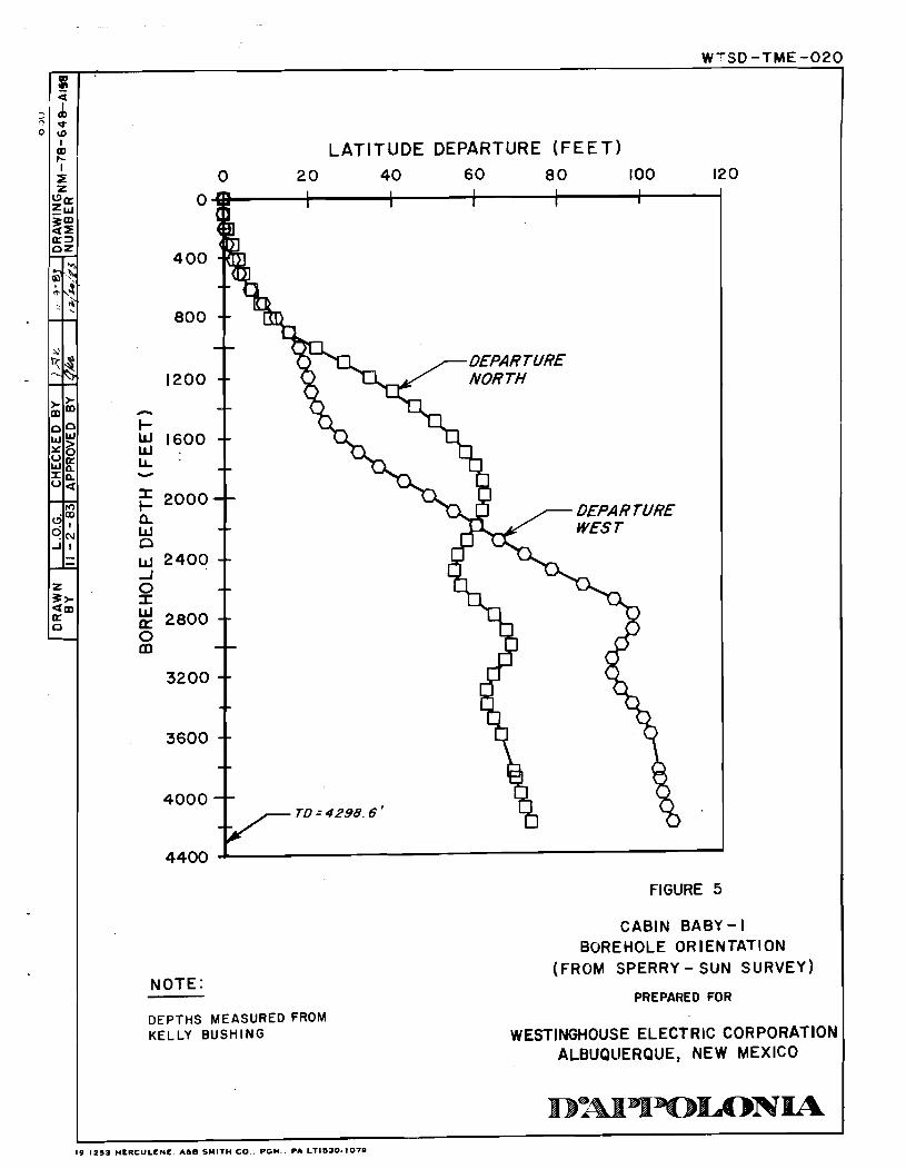

WTSD- TME- 020
m- TUBING
CROSS OVER SUB
CIRCULATING VALVE (BALL BAR SLEEVE) CROSS OVER SUB
SHUT-IN TOOL 2.88 FEET CLOSED 2.23 FEET OPEN
CROSS OVER SUB 1 - 1 7 SENSOR CARRIER
"J" SLOT TOOL AND MANDRIL 1.4 FEET THROW
ELEMENT CONNECTOR
4.61 FT. I 11 L PACKER ELEMENT
-ELEMENT CONNECTOR m- MANDRIL
& CROSS OVER SUB
SPACERS
ELEMENT CONNECTOR
4.61FT. PACKER ELEMENT
ELEMENT CONNECTOR
TAIL PIPE
BIT SUB
NOT TO SCALE
NOTE: FIGURE 6
PI IS PRESSURE BELOW THE TESTED INTERVAL; P2 IS PRESSURE IN THE 'TESTED INTERVAL ;
STRADDLE PACKER
P3 IS PRESSURE IN THE WELL ANNULUS ABOVE THE ASSEMBLY CONFIGURATION TESTED INTERVAL.
PREPARED FOR
WESTIN GHOUSE ELECTRIC CORPORATION ALBUQUERQUE, NEW MEXICO

, TSD - T M E - 0 2 0
3 9 0
LO ? w 6 c
I Q) P- I 5 z
OK Z w 9"' a5 a3 nz
Q , .
DOWNHOLE - 'ITA EPSON M X - 8 0
TERMINAL PRINTER
- PRINTOUT
r, C
- DATA -
H P 9 8 7 2 B DATA PLOTTING FROM
P R l NTOUT
-DOWNHOLE DATA PLOT-
TAPE DATA- - ACQUISITIOFI PROGRAM -
PLOTTER TAPE FOR ANALYSIS TAPE DATA, 34
-DATA STORAGE - P L O T T I N G PROGRAM - PLOT -- I CONTROL DISPLAY
z z :g * O
Eg 5: --
to
PC o= A\ - - Z 9> am a 0 -
SOFT WARE
H P 5 9 3 0 6 A R E L A Y
ACTUATOR
H P 8 5 A C A L C U L A T O R
M A I N D R I V E
L
i
S I X CHANNEL FREOUENCY DATA
a 5 (MULTIPLEX)
TO
TRANSDUCFRS
FIGURE 7
SCHEMATIC DIAGRAM OF DATA ACQUISITION SYSTEM
PREPARED FOR
WESTINGHOUSE ELECTRIC CORPORA'rION ALBUQUERQUE, NEW MEXICO
ID I S I 2 5 3 HERCULENE A h 0 SMITH CO PGH PA LT1530.107*
COUNTER
LYNES SC-2
I N T E R F A C E
CONTINUOUS
DATA COLLECT I O N - HP 5316 A FREQUENCY


- - t(flow) =5.5 rnin. dt =23.15rnin.
m = 518 psl/cycle q = 169 BPD B=I.O
- p=I.30cp - - rn =518 psi - - - h=120.6 ft. - - - - - - - - - - - - - - - - - - - - - - - - - - - - - - - I I I I I I I I
a (f loW)+dn/dT
FIGURE 9
HORNER PLOT OF DST-4178/FBU
- - - - t(flow)=25.75 min. - - dt = 147.4 rnin. q = I24 BPD B =l.O p=l.30cp rn = 305 psi h ~120.6 ft. - - - - - k= 162-6qBp = 0.7 1 md - rnh - - K=I.~XIO-~ ft./day
- - - - - - - - - - - - - - - - - - - - - - I I I I I I I I
I 16
(T ( f l o w ) +dT) /dT
FIGURE 10
HORNER PLOT OF DST-4178 / SBU

FIGURE 12
SLUG TEST PLOT FOR DST-4178/SLUG

Elapsed Time in Minutea Start Dater 09/07/1983
Start Timer 131 42: 05 FIGURE 13
L inear-Linear Plot CB- l.S/DST-4 138
REAL- TIME PLOT OF DST-4138: OLDS SANDSTONE

t(flow)=12.2 min.
p=1.54cp m =I932 psi/cycle m= 1932psi
h t 3 2 . 4 ft. k=162'6qBp =2.2r,0'2md
mS, ~ g 4 . 5 x 1 0 - ~ f t . / d a ~
- - - - - - - - - - - - - - - - - - - - - - I I I
(1 (f lor) +dl) /dl FIGLIRE 14
HORNER PLOT OF DST-41381FBU
(T (flow) +dT) /dT
FIGURE 15
HORNER PLOT OF DST-41381 SBU

--A -
WTSD-TME- 020
10 10 1 10 Elapsed lime in Minutes
FIGURE 16
EARLY -TIME SLUG TEST PLOT FOR DST-4138lSFL

PRESSURE ABOVE TEST INTERVAL
PRE-TEST STATIC PRESSURE PRESSURE BELOW TEST INTERVAL .............. ..... ....................................... .......................................... ""."".........I..." .".........- ..-.. -. "........_" -..- ...................... .-..-.I
..___.......-..I
-. .."' -......- -LL-
aL.)LC.----
-4.-
&&*-
---SLUG
....
0 Elapsed Time in Minutme I
Start Dater 09/12/1983 Linear-Linear Plot -I K Start Timer 04: 38: 16 FIGURE 18 CB-1.1 l/DST-4100 m
I 0
REAL-TIME PLOT OF DST-4100: RAMSEY SANDSTONE N 0

(T ( f l o w ) +dT) /dT
FIGURE 19
t (flow) = 15.2 min. dt ,in,, = 93.08 min.
q = 6.5 BPD B = 1.0 p = 1.54 cp m = 2230 psi - - h = 32.4 ft. - - - - 162.6 qBp - - k = = 2.3 x md
- mh - - - K=4.7 x ft./day - - - - - - - - - - - - - - - - - - - - - - - - I I I .
HORNER PLOT OF DST - 41001 FEU
- - - - t(fiow) = 55.85min. dt final = 261.65 min.
q = 4.8 BPD B = 1.0 p = 1.54 cp
- - m = 1276 psi
- - h ' 32.4 ft. - - - - - - - - K=6.0x 10 '~ ft./day - - - - m = 1276 psi/cycle - 7 - - - - - - - - - - - - - - -
I I I I I I I I
CT (f 1 ow) +dT) /dT FIGURE 2 0
HORNER PLOT OF DST-4100/SBU

WTSO -TME-020
-2 10 -
I 1 1 1 1 1 1 1 I 1 1 1 1 1 1 1 I 1 1 1 1 1 1 1 2 3 4
10 1 18 10 10 18 Elqmed Tine in Minute.
FIGURE 22 EARLY - TIME SLUG TEST PLOT FOR DST -4100/SLUG


(T (f lor) +dTl /dT
- FIGURE 24
HORNER PLOT OF DST-4044/FEU
I (flow) = 15.05 mln. dt = 3730.1 min.
q = 5.5 BPD m = 46,000 psl/cycle B = 1.0
r = 1.54 cp m = 46,000 psl h = 53.2 11. - - -
- - 162.6 q Bp k = =6 x md - - mh - - K = 1 x 1 6 ~ fl./day - - - - - - - - - - - - - - -
- - - - ...... ......... ....
&
(T (f lor) +dT) /dT
FIGURE 25
EXPANDED -SCALE HORNER PLOT OF DST - 4044 / FEU

WTSD- TME-020

WTSD- TME-020
(T (flow) + d ~ ) /m
FIGURE 2 7
HORNER PLOT OF DST-765/SBU
- - t(flow) = 32.3 min. - - dt ,,,,, = 2974.95 min. -
q = 1.1 BPD B = 1.0 r = 1.7 cp m = 16,400 pel h = 1960.4 ft.
162.6 q Br k= = 9 xlCf6 md
mh m - 16,400 psi/cycle
K = 2 x 16' ft./day
- - - .. - - - - - - - -a*... - .-...... - -...
a*... - ... - -.. ... - .-. . . -... ..... - . . . . . . . . . - .-. . . . .
(T (f lo.) +dn /dT
FIGURE 2 8
EXPANDED -SCALE HORNER PLOT OF DST- 765/SBU

FIGURE 29
EARLY-TIME SLUG TEST PLOT FOR DST-765/SLUG

0 Field analyses
0 Laboratory analysis

A P P E N D I X A
J U S T I F I C A T - I O N

SANDIh NATIONAL LABORATORIES hlbuquerque, hew Piexico 87185
To: Arlen Hunt - DOE/IIPO , Dev Shukla - iSC/D'Appolonii From: Rl Lappin - 6331flg-
Subject - DRAFT SCOPE OF ADRK FOR DRILLING RND TESTING OF "CABIN BABY", SEC. 5, T23S. R31E - PHASE I (DHG)
INTRODUCTION
This memo provides a draftlscope of work for drilling and hydrologic testing to be carrled out at Cabin Ba b y or. if need be, in a companion hole to be drilled on an extension oi the existing Cabin Baby pad: this posslbie new hole is here termed "Cabin Baby-2". It is intended that the bulk of the work described here be fielded by D'Hppolonia/TSC, under the technical supervision of Sandia National Laboratories.
Obviously, some of the specifications given here may be either in error or incomplete: ~f so feel free to contact either me or Don Gonzalez . OBJECTIVES
The overall effort planned for the Cabin Baby pad has three main objectrves:
1 . Determination of the head ~otentlals, in situ hydrologic properties, fluid compositions, and brlne densities within the Hustler Formation.
2. Determination of the head potentials, in sltu hydrologic properties, fluid compositions. and fluid densities wlthin permeable zones in the Ramsey Member of the Bell Canyon formation.
Acconplishment of objectives 1 and 2 will allow reliable a priori calculation of directions of fluid movement to be expected at Cabin Baby in the event of interconnection of the Bell Canyon and Rustler aquifers.
3 . Intentional interconnection of the Rustler and Bell Canyon "aquifers", followed by monitoring of the actual direction(s) of resultant fluid movement.
The work described here, part of the overall effort to be carried out the Cabin Baby pad. has one major objective:
I. Collection of the data required for the best possible estimation of both "fresh-water" and "brine" heads withln selected "permeable" sands contained in the Ramsey Member of the Bell Canyon Formation. This objective, in turn, requires:
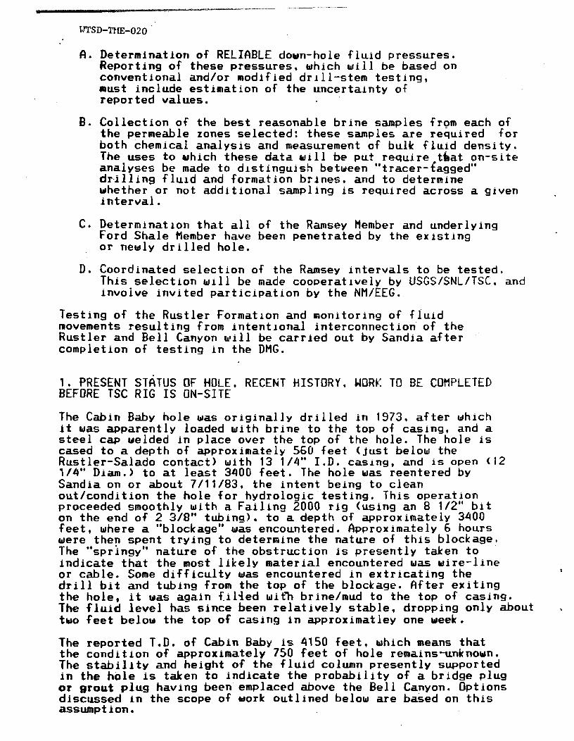
A. Determination of RELIQBLE down-hole fluid pressures. Reporting of these pressures, which will be based on conventional and/or modified drill-stem testing* must include estimation of the uncertainty of reported values.
B. Collection of the best reasonable brine samples from each of the permeable zones selected: these samples are required for both chemical analysis and measurement of bulk f Luid density . The uses to which these data will be put require =teat on-site analyses be made to drstinguish betideen "tracer-tagged" drilling fluid and formation brines, and to determine whether or not additional sampling is required across a given interval.
C. Determination that all of the Ramsey Member and underlying Ford Shale Member have been penetrated by the exlsting or newly drilled hole.
D e Coordinated selection of the Ramsey intervals to be tested. This select ion wlll be made cooperat lvely by USGS/SNL/TSC, and invoive invited participation by the NM/EEG.
Testing of the Rustler Formation and monitoring of fluid movements resulting from intentional interconnection of the Rustler and Bell Canyon will be carried out by Sandia after completion of testing in the DHG.
I . PRESENT STATUS OF HOLE, R E C E ~ T HISTORY, WORK TO BE COHPLETED BEFORE TSC RIG IS ON-SITE
The Cabin Baby hole was originally drilled in 1973, after which it was apparently loaded with brine to the top of casing, and a steel cap welded in place over the top of the hole. The hole is cased to a depth of approximately 560 feet (just below the Rustler-Salado contact) with 13 1/4" I.D. casing, and is open (12 114" Diam.) to at least 3400 feet. The hole was reentered by Sandia on or about 7/11/83, the intent being to clean out/condition the hole for hydrologic'testing. This operation proceeded smoothly with a Failing 2000 rig (using an 8 1/2" bit on the end of 2 3/8" tubing). to a depth of approximately 3400 feet, where a "blockage" was encountered. Approximately 6 hours were then spent trying todetermine the nature of this blockage. The "springy'* nature of the obstruction is presently taken to indicate that the most likely material encountered was uire-line or cable. Some difficulty was encountered in extricating the I
drill bit and tubing from the top of the blockage. flfter exiting the hole, it was again f.il4ed with brine/mud to the top of casing. The fluid level has since been relatively stable, dropping only about . tuo feet below the top of casing in approximatley one week.
The reported T.D. of Cabin Baby is 4150 feet, which means that the condition of approximately 750 feet of hole remains-unknown, The stability and height of the fluid column presently supported in the hole is taken to indicate the probability of a bridge plug or grout plug havlng been emplaced above the Bell Canyon. Options discussed in the scope of work outlined below are based on this assumption.

WTSD-TME-02 0 The USGS will run standard geophysical logs In Cabln Baby to a depth of approximately 3400 feet, probably during the week of
SCOPE OF WORK
fl. HDLE COflPLETION
This section describes options likely to be encountered during attempts to complete Cabin Baby (or Cabln Baby-2) to adequate depth for testing. Steps are described, as much as possible, in sequence.
I. Initial hole reentry, We request that Cabin Baby initially be reentered with a sllm tool/spear, the intent being to penetrate through the blockage at 3400 feet and to tag either T.D. or the top of any plug that may be present below 3400 feet. If successful, this operation will greatly decrease remaining uncertainties concerning hole completion. If unsuccessful, the contractor should proceed to step 11. It is intended that no more than 2 days be spent in attem~ting to penetrate the blockage; :lodever, the option must be retained to extend this time period.
11. fishing. After the attempt to penetrate the 3400-foot blockage with a slim tool/spear, a perlod of no more than two days should be expended in attempting to fish the hole to T.D. or the first plug below 3400 feet. However, the option must be. retained so that, if sufficient progress is being made, this time span can be increased; in addition, if a plug is encountered, a second fishing operatlon may be needed.
f3. If the fishing operation is successful in opening the hole to T.D., the hole may then need to be logged, in order to determine whether or not the base of the Ramsey has been reached. The attempt is presently being made to obtain "existing" geophysical logs for Cabin Baby. If existing logs prove to be adequate, and indicate both that the Ramsey is completely penetrated and the Ford Shale at least entered, and that the hole T.D. recorded after fishing shows that the entire Ramsey is accessible for testing, no drilllng will be necessary as part of this contract. If existing logs are inadequate, the hole will need to be logged before proceeding further.
If either existing or newly run logs indicate that the Ramsey has not been completely penetrated in the existing Cabin Baby, the hole will need to be drilled through the bottom of the Ramsey and at least into the Ford Shale. During this drilling, 100% core should be taken. This core should be a minimum of 2" in diameter, resulting in a minimum hole diameter of 5". Maximum hole diameter should be 12 1/4".
B. If the fishing operatlon is successful, but only -opens the hole to a plug above T.D., this plug should be drilled out. A second fishing operation may then be needed to reach T.D.; once T.D. IS reached, the drilling and logging options remain as In IIIR above. If a plug is encountered, a blow-out preventer should be used during drilling to T.D.. because of the slight possibility of encountering pressurized brine.

C. If either the initlal or a subsequent fishing operation is unsuccessful, Cabin Baby will be filled with brine and abandoned. H companion hole. Cabin Baby-2, will then be drilled to the bottom of the Ford Shale. This hole will be sited on an ' extension of the existing Cabin Baby pad. The decision to drill a new hole rather than attempting to deviate the exlsting.Cabin Baby is based on concern about the capability to emplace and retreive, through a deviated hole, the 15-to-20-foot packer s-trings that will be used in hydrologlc testing. In adchtion, there is concern about the hydrologic reliability of a ?plug newly emplaced abovelwithin "trash", ie, whether or not the presence of this hole would affect the results of hydrologlc testing. Since Sandia has an ongoing contract with an earth mover, responsibility for both hole siting and pad preparation will be taken by Sandia.
Several speclfic points and options must be kept in mind in the possible drilling of Cabin Baby-2:
1 . The intent would be to mlnimlze corlng in the upper part of Cabin Baby-2. Sandla is presently drilling hole H-11 (hydrology) approximately one mile from the Cabin Baby pad. Drilling there should be completed before the Cahin Baby slte is occupied. The option must be retained, depending upon results in H-11, to take core at the following depths/stratigraphic locations: a) across the Dewey Lake-Rustler contact; b) within the Magenta dolomite: c) -within the Culebra dolomite: and d) across the Hustler-Salado. contact.
2. Regardless of whether or not the Rustler is cored, the intent rlould be to take approximately 25 feet of core atlacross each of the major stratigraphic contacts (anhydritelhalite) within the Castile Formation. We do not expect to encounter pressurized brine in either Cabin Baby or Cabin Baby-2; nonethless, prudence dictates that a blow-out preventer be used during drilling of the Castile in Cabin Baby-2.
3. We would want 100% core from the top of the Be1 1 Canyon to the Bottom of the Ford Shale flember. Analysis of this core would aid greatly in understanding of the material and hydrologic properties of the upper portion of the Bell Canyon Formation near the WIPP, both above and immediately below the "Bell Canyon aquifer".
4. The initial assumption is t-hat Cabin Baby-2, if needed, should be drilled such that 5 1/2" T.D. casing can be set to the Rustler-Salado contact. TSC will provide this casing, or will purchase equivalent casing to replace same if i t must be taken from the Sandia "porta-camp" during drilling. TSC will also perform an informal survey to determine the likelihood of successful drillingltesting in a "slim" hole at Bell-Canyon depths.
5. As soon as possible after completion of drilling, C&i.n Baby-2 would be geophysically logged by the USGS. It is anticipated that a "normal" suite of logs, including density, resistivity, gamma, ~amna-gamma, neutron, sonic, and caliper logs would be run. In addition, ue would log at least part of the hole using the accoustic televiewer. Ue anticipate that this logging operation uould take two or three days.

6. 'Drilling should be done using a brinelmua that is tagged with a suitable tracer. ie, one that can be detected using "on-site" analysis. This is required in order to allow later distinction betueen formation uaters 'and drilling fluids*
7 . Immediately after completion of logging, a meeting would be convened, at which USGS, with assistance from SNL and TSC, uould select the intervals to be hydrologically tested within. the Bell Canyon. Because of their past criticism of intervals ofiitted from testing within the Bell Canyon, a representative-of the NM/EEG uould be invited to attend this meeting.
0. HYDROLOGIC TESTING AND WATER SAHPLING
A detailed test plan for hydrologic testing in Cabin Baby or Cabin Baby-2 wlll be provided to TSC durlng the week of 8/1/83. A summary of the testing requirements 1s given here, hopefully in sufficient detail to allow cost estimation,
I. Drill-Stem Testing
He anticipate doing drill-stem tests or modlfied drill-stem tests in from 2 to 5 zones within the Bell Canyon that are expected to be "permeable", This testlng must be carried out with consideration of posslbly extending "fiow" tlmes in relatively tight zones. We expect testing to require approximately three days for each sand tested; with the resultant total time ranging- from 6 to 15 .days. however, the opt ion must be retained, based on initial test results, oflengthenlng the flow tlme for each drill-stem test. We recommend that drill-stem testing be carried out using 2 3/8" tubing (to be purchased by TSC), and that TSC contract Lynes, Inc. for a "triple" tool, which allows pressure monitoring both below and above the packed-off interval, as well as within it.
The drill-stem testing will allow estimation of both static downhole fluid pressures and hydrologic properties in the permeable zones tested.
11. Fluid Sampling During Drill-Stem Testing
A fluid sample will be collected as carefully as possible at the end of each drill-stem test. The possibility of improving the quality of fluid analyses by allowing each packed-off zone to flow before the initiation of drill-stem tests should be considered.
The fluid samples collected will allow prel lmlnary calculation of estimated fluid pressures as a function of height above the points of pressure measurement. This Information is required for calculation of directions of fluld movement in the event of a breach connecting the Bell Canyon and Hustler "aquifers".
I 11. Slug-Ui thdrawal or Pressure-Pulse Testing
We will require that at least. one slug-withdrawal or pressure-pulse test be carried out in each selected zone. This test will provide a second estimate of in situ hydrologic properties. Sandia has the equipment necessary for these tests,

and will make this equipment available. He estimate that the time required for this testing will be 1 day per zone tested. The total time required for this testing should, therefore, range from 2 to 5 days.
IV. Fluid Sampling - Sampling Chamber We do not, in advance, place great confidence in the quality of fluld analyses made during drill-stem testing. Therefere, we will want to reserve up to three days for attempts to sample formation fluids from the selected "permeable" zones using a downhole sampler that Sandia will provide. This apparatus consists of a vacuum cylinder with portals that can be opened and closed with a solenoid. The strategy will be to place the cylinder opposite each of the "permeable" zones and collect a sample, after reducing the fluid column.in the hole sufficiently to assure that fluids wil l enter the hole from the Bell Canyon. The capability for analysis of the tracer used in the drilling fluid at the surface is required, in order to determine the level of contamination, if any. of each sampie.
V. Fluid Samplinq - Straddle Packers
We anticipate that neither samples collected during drlll-stem tests nor those collected using the sample chamber will be of sufficiently high quality to provide adequate confidence in fluid densities and compositions., and, hence, in calculated directions of fiuid movement durlng the intentional interconnection of Bell Canyon and Rustler. We therefore anticipate that i t will be necessary to. sample formation fluids from the Bell Canyon using straddle-packer assemblies. Ue recommend that TSC obtain lothese assemblies from Lynes, Inc. In order to allow sufficient flow time for collection of each sample, we recommend that approximately 1.5 days be allowed per zone for collection of samples. The option must be retained to extend this time if necessary. If, of course, analysis indicates that samples taken during either the drill-stem tests or using the sample chamber are not appreciably contaminated with drilling fluids, this step of sampling can be deleted.
C. Temporary Abandonment of Hole.
At the completion of hydrologic testing in the Bell Canyon, the hole will be abandoned until testing of the Rustler hydrology by Sandia can begin. Accordingly, TSC should purchase a bridge packer from Lynes, for emplacement at a depth to be determined after logging and testing of the hole.
Distribution:
6330 - W . D. Weart 6331 - G. E. Barr 6331 - D. J. Rorns 6331 - D. D. Gonzalez 6331 - S. J. Lanibert

APPENDIX B
FIELD OPERATIONS PLAN
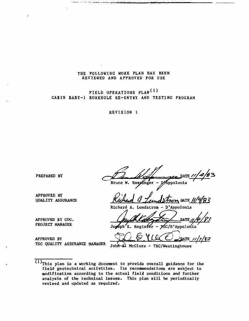
THE FOLLOWING WORK PLAN HAS BEEN REVIEWED AND APPROVED FOR USE
FIELD OPERATIONS PLAN( l) CABIN BABY-1 BOREHOLE RE-ENTRY AND TESTING PROGRAM
REVISION 1
PREPARED BY
APPROVED BY QUALITY ASSURANB
APPROVED BY COG. PROJECT MANAGER
Richard A. Lundstrom - D'Appolonia
APPROVED BY TSC QUyIn MANAGER ~ o h u McClure - TSC/Westinghouse
(l)This plan is a working document to provide overall guidance for the field geotechnical activities. Its recommendations are subject to modification according to the actual field conditions and further analysis of the technical issues. This plan will be periodically revised and updated as required.

BELL CANYON HYDROLOGIC TESTING PROGRAM PLAN CABIN BABY-1 HOLE
1.0 INTRODUCTION
This work plan outlines the objectives and scope of work for fishing,
drilling, and hydrologic testing at the Cabin Baby-1 hole in Section 5,
T23S, R31E, in Eddy County, New Mexico. The hole is located within the
WIPP (Waste Isolation Pilot Plant) site near the south edge of the
site. The hole was drilled as a hydrocarbon exploration hole and was
turned over to the U.S. Department of Energy (DOE) after it was found to
be a "dry hole." Testing in this borehole is being conducted for the
DOE as part of the ongoing site characterization activities for the
WIPP.
This plan provides overall guidance for the field activities. Modifi-
cation can be expected with adjustment to actual field conditions and
further analysis of technical issues. This plan will be periodically
revised and updated as required.
2.0 OBJECTIVES
The objectives of this testing program are to:
a Provide data on the hydrologic properties, in- cluding hydrostatic head potential of selected permeable sand zones in the Bell Canyon Forma- tion.
a Provide representative fluid samples from selected permeable zones in the Bell Canyon Formation which will be used to determine fluid composition and density.
These data will be used to refine calculations of the direction of fluid
movement should the Bell Canyon and Rustler formations ever be intercon-
nected. If the fluid flow direction is found to be downward, the data
may be used to estimate Bell Canyon flow velocities and travel times.
If the flow direction is found to be upward, the data may be used to
calculate potential flow rates into the Rustler Formation.

3.0 ORGANIZATION
Direction of field operations and technical matters will originate with
the WIPP Technical Support Contractor (TSC) under the supervision of
J. K. Register of DIAppolonia and C. C. Little of Westinghouse Electric
Corporation. Service contracts, including drilling, coring, and geo-
physical logging, as well as additional support services, will be let
and administered by Westinghouse Electric Corporation. Contracts for
mud and other drilling support services will be administered by Salazar
Brothers Drilling, Inc. DIAppolonia is not anticipated to let or admin-
ister any additional service contracts.
The hydrologic testing program is under the direction of R. L. Beauheim,
Hydrogeologist with DIAppolonia. Identification of stratigraphic
features, core and cuttings logging, and other geologic interpretations
will be provided by DIAppolonia geologists under the direction and
supervision of Mr. Beauheim.
Assistance in the supervision of fishing, drilling, and testing oper-
ations will be provided by R. S. Popielak, Project Supervisor and R. L.
Olsen, Senior Project Geochemist, both with DIAppolonia, and R. L.
Oinonen, full-time drilling supervisor and consultant to DIAppolonia, on
an as-needed basis.
Quality control on day-to-day operations will be administered by Mr.
Beauheim. The overall Quality Assurance program for the TSC is the
responsibility of J. E. McClure of Westinghouse. Field audits and
technical and procedural reviews, however, will be provided by R.
Lundstrom and other members of DIAppolonia's Quality Assurance staff.
Appendix A presents the Quality Assurance Plan for this program.
4.0 PRESENT HOLE CONDITIONS
The existing data on the Cabin Baby-1 hole are sparse. The hole was
drilled in 1974-1975 to a reported depth of about 4150 feet. The hole
is cased to a depth of about 650 feet (just below the Rustler-Salado
contact) with 13-3/8-inch casing, and is 12-1/4-inch open hole to at

l e a s t a dep th of 3400 f e e t . A c a l i p e r l o g by Dresser A t l a s i n d i c a t e s a
h o l e d iamete r of about 9 i nches below about 3950 f e e t . When Sandia
Nat iona l Labo ra to r i e s (Sandia) reen te red t h e ho l e i n Ju ly 1983, they
were unab le t o g e t below about 3400 f e e t due t o a blockage. Sandia
s p e c u l a t e s t h a t t h e blockage may be w i r e l i n e o r c a b l e , perhaps on t op of
a b r i dge p lug , g r o u t plug, o r s h e l f c r ea t ed by t h e ho l e diameter
r educ t i on . Sandia l e f t t h e h o l e f i l l e d w i th brinelmud t o t h e t o p of
c a s i n g which should have c r ea t ed a h y d r o s t a t i c head a t t h e bottom of t h e
w e l l cons ide r ab ly i n excess of t h a t a n t i c i p a t e d t o e x i s t i n t h e Be l l
Canyon Formation. The f a c t t h a t t h e f l u i d l e v e l i n t h e w e l l i s
d e c l i n i n g on ly very s lowly may i n d i c a t e t h a t t h e Be l l Canyon is hydrau-
l i c a l l y i s o l a t e d from t h e upper p a r t of t h e ho l e , hence Sandia ' s
s p e c u l a t i o n about t h e presence of a plug. The slow d e c l i n e , however,
cou ld be t h e r e s u l t of a mud cake on t h e h o l e w a l l a t B e l l Canyon
dep ths .
Data on permeable zones i n t h e B e l l Canyon have been der ived from d r i l l -
s t em tests (DST's) performed i n AEC-7, AEC-8, and ERDA-10. Tested zones
have inc luded t h e Lamar Member, t h e Ramsey Member and some pre-Ramsey
sands. A s d e sc r i bed i n Mercer (1983), t h e hyd rau l i c c o n d u c t i v i t i e s of
v a r i o u s zones i n t h e B e l l Canyon range from 2 x t o 5 x lo-' f t l d a y
(7 x 10-lo t o 2 x cmlsec). The f low pe r iods of t h e DST's ranged
from 10 t o 480 minutes , and t h e bu i ldup pe r i ods ranged from 60 t o 748
minutes . Measured f l u i d d e n s i t i e s ranged from 1.060 t o 1.165 g/cc .
S t a t i c f l u i d l e v e l s i n B e l l Canyon w e l l s t y p i c a l l y reach t h e e l e v a t i o n
of t h e upper R u s t l e r Formation.
5.0 HOLE REENTRY
P r i o r t o f i s h i n g , t h e d r i l l i n g c o n t r a c t o r p l ans t o r e e n t e r t h e ho le
u s i n g a 7-718 t o 9-inch r o t a r y b i t t o c l e a n t h e h o l e above t h e lodged
o b s t r u c t i o n and t o t a g t h e t o p of t h e obs t ruc t i on . A t t h i s po in t t h e
c o n t r a c t o r p l a n s t o u se a f i s h i n g consu l t an t t o determine t h e na tu r e of
t h e o b s t r u c t i o n and t o d i r e c t t h e f i s h i n g opera t ion . These ope ra t i ons

will also be observed by a DtAppolonia/TSC drilling supervisor and clear
the hole.
Based on Sandia's observations of the nature of the lodged obstruction,
the larger rig designated for this operation should be able to pull the
obstruction. Fishing tools will probably consist of coil-type overshots
that will hook the fish should it be wireline or cable as speculated.
If a plug is encountered, a reasonable effort will be made to determine
the nature of the plug. The occurrence of a plug in the hole will
seriously affect the feasibility of testing in the well due to the
indeterminable amount of cement invasion into the aquifer. If a plug is
present or if removal of the obstruction in the hole seems impossible,
consideration should be given to drilling a new hole.
If a plug is not encountered, the fishing operation is successful, and
the total depth (T.D.) is tagged, the hole will be cleaned and geo-
physical logs will be run in the lower part of the hole (about 3400 feet
to T.D.) by a geophysical logging subcontractor to determine if the pre-
Olds sandstones (Hays sandstone) of the Bell Canyon Formation has been
penetrated and to determine hole diameter and wall condition. The
following geophysical logs will be run at this time:
a Natural Gamma Compensated Neutron Porosity Neutron Density Caliper
If the Hays sandstone is penetrated and the hole walls are suitable for
setting packers, no drilling will be required and the testing will
proceed as outlined below.
If the geophysical logs indicate that the Hays sandstone was not pene-
trated, the hole will be extended about 120-180 feet using conventional
rock coring techniques. The core diameter will be 4 inches and the hole
diameter about 7-718 inches. The hole will then be reamed to the

diameter of the existing hole. A blow-out preventer will be used during
hole deepening and H2S gas monitors will be installed near the drilling
rig platform and at the mud pit.
The total depth of the hole will then be geophysically logged by USGS or
a commercial firm as outlined below.
6.0 TESTING PROGRAM
The following testing plan is based on the assumption that no insur-
mountable difficulties are encountered during restoration of the Cabin
Baby-1 hole to its original total depth and that the condition of the
hole does not interfere with the testing. If a new hole is drilled,
testing will also follow the plan outlined below.
The testing program presented in this plan is, in general, responsive to
the "Draft Scope of Work for Drilling and Testing of 'Cabin Baby,' Sec.
5, T23S, R31E - Phase I (DMG)" developed by Sandia National Laboratories
and presented to the TSC on July 27, 1983. The testing program will
consist of the following efforts:
Observations during fishing. This will include monitoring down-pressure, fishing tools used, and pulling effort . Observations durine drilling. This will include
L, L,
at a minimum monitoring of the mud balances, rate of drilling progress, gas presence.
Geophysical logging. This will facilitate the determination of the contacts between porous, hence potentially water-bearing, strata and impermeable confinements. This information will be instrumental in detailed elaboration of the drill-stem testing program.
Drill-stem testing (DST). Testing will be performed in zones of the Bell Canyon Formation indicated from geophysical logs as potentially permeable strata.
Water quality sampling. Water samples will be extracted from tested horizons by means of swabb- ing the fluid from the 2-318" tubing after

completion of a DST sequence. I n add i t ion t o swabbing, t he samples may be co l l ec t ed with a downhole f l u i d sampler.
A d e t a i l e d d i scuss ion of t e s t i n g procedures planned f o r the Cabin Baby-1
w e l l program is presented below.
7.0 DRILLING
During deepening of t he Cabin Baby-1 we l l , t h e fol lowing information
w i l l c o n t r i b u t e t o a b e t t e r understanding of the hydrologica l systems of
i n t e r e s t .
Monitoring of the d r i l l i n g r a t e . General ly, p r o l i f i c a q u i f e r s a r e d r i l l e d f a s t e r than " t i g h t " strata. This r e s u l t s from r e l a t i v e l y loose mat r ix , higher po ros i ty , and o f t e n higher pore pressure .
Monitoring- Cabin Baby-1 is not expected t o i n t e r c e p t a flowing a r t e s i a n aqu i fe r . However, such an a q u i f e r could be e a s i l y de tec ted by an inc rease i n mud volume.
G a s monitoring. The Be l l Canyon is known t o produce gases , p r imar i ly hydrocarbons, i n some p a r t s of t he basin. The presence of gas i n out- flowing mud may be an i n d i c a t i o n of a penet ra ted aqu i fe r .
The Cabin Baby-1 hole deepening w i l l be done i n t h e presence of hydrol-
o g i s t s and geo log i s t s experienced i n deep wel l d r i l l i n g and knowledge-
a b l e about hydrologic systems which may be present at the s i t e .
GEOPHYSICAL LOGGING
A s soon a s the t o t a l depth is reached and the hole is cleaned and con-
d i t i o n e d , a s u i t e of geophysical logs must be run. This s u i t e should
inc lude t h e fol lowing ( i n t e r v a l t o be logged and a n t i c i p a t e d logger a r e
noted) :
Dual Latero log - Measures deep and shal low r e s i s t i v i t y ; provides information on l i t h o l o g y and mud invas ion (from about 200' above top of B e l l Canyon t o T.D., comnercial logging f i rm).

Natural Gamma - Measures natural gamma radiation emitted by rock. Used to identify clays and shales (entire open hole, USGS).
Compensated Neutron - Measures density of hydrogen atoms (concentrations) in the formation; used to estimate porosities (entire open hole, USGS).
Neutron Density - Measures density of electrons in the formation; used to estimate bulk densities and porosities (entire open hole, USGS).
Borehole Compensated Sonic - Measures sonic travel times; used to detect fractures and estimate porosities (entire open hole, USGS).
Three-Arm Caliper - Measures hole diameter; used to calibrate other logs and to select packer seating depths (from about 200' above top of Bell Canyon to T.D., USGS).
Borehole Deviation - Measures deviation of hole from true vertical; used to calculate true ele- vations of contacts (will be run after all test- ing is completed, entire hole, commerical logging firm).
Acoustic Televiewer (will be run after all test- ing is completed) - Converts attenuation of sonic signal to "picture" of borehole wall; used to identify fractures and their orientation (may be used if presence of fractures is suspected, entire open hole, USGS).
All logging will be supervised by DIAppolonia geologists or hydrologists
to ensure that log quality is adequate. Once complete logs of the hole
are obtained, the intervals to be tested will be selected jointly by the
DOE, TSC, Sandia, USGS, and the NM Environmental Evaluation Group
(EEG). We estimate that a maximum of five zones will be selected for
DST1s.
9.0 DRILL-STEM TESTS
Drill-stem testing equipment, consisting of a straddle packer assembly,
J-slot tool, transducers above, below, and between the packers, and a

conduct ing w i r e l i n e , w i l l be provided by Lynes, Inc. A computerized
d a t a a c q u i s i t i o n and process ing system w i l l a l s o be employed. Two sets
of computer equipment w i l l be used. One set w i l l be used cont inuous ly
f o r d a t a a c q u i s i t i o n , and the o t h e r set w i l l be used f o r on-si te d a t a
process ing and a n a l y s i s and w i l l a l s o se rve a s backup equipment i n ca se
one o r more components i n t he f i r s t set malfunctions.
Following s e l e c t i o n of t he i n t e r v a l s t o be t e s t e d , d r i l l s t e m tests w i l l
be performed working from the lowest i n t e r v a l up. The packer s e p a r a t i o n
w i l l be ad jus t ed a s necessary t o achieve the d e s i r e d s t r a d d l i n g . Af t e r
reaching t h e d e s i r e d depth , t he packers w i l l be i n f l a t e d and t e s t e d by
pushing or p u l l i n g t h e 2-3/8 inch tub ing t o ensure t h a t they have sea t ed
proper ly . The water p re sen t i n t h e tub ing w i l l then be swabbed out.
P r i o r t o t h e a c t u a l DST, t h e formation h y d r o s t a t i c p re s su re w i l l be
monitored u n t i l s t a b l e . The t i m e of monitoring w i l l depend on formation
pe rmeab i l i t y and amount of overpressure due t o packer i n f l a t i o n .
The a c t u a l DST begins with opening a shut- in t o o l which a l lows the water
i n t h e s t r a d d l e d i n t e r v a l t o e n t e r t he tubing. Due t o t he l a r g e pres-
s u r e d i f f e r e n t i a l (between t h e tub ing and t h e s t r a d d l e d i n t e r v a l ) , water
under t he i n i t i a l s t a t i c formation p re s su re flows r a p i d l y towards t h e
borehole and up t h e tubing s t r i n g . This is the f i r s t flow per iod
(FFL). This per iod begins wi th a drop i n p re s su re from static (shut - in
t o o l c losed) t o a p re s su re corresponding t o t h e weight of t he water
remaining i n t he tub ing ( a f t e r swabbing) above the t ransducer . As water
rises up t h e tub ing s t r i n g , t h e p re s su re w i th in the s t r a d d l e d i n t e r v a l
i n c r e a s e s , reducing t h e p re s su re d i f f e r e n t i a l and t h u s , t h e f low
v e l o c i t y .
A f t e r a minimum recovery of t h i r t y percent of a v a i l a b l e d i f f e r e n t i a l
p r e s s u r e dur ing t h e f i r s t flow (FFL), t h e shut- in t o o l w i l l be c losed ,
s topp ing t h e flow of water up the tubing. This i s the beginning of t he
f i r s t p r e s s u r e buildup period (FBU). The formation w i l l be allowed t o
recover i n the f i r s t p ressure bui ldup period f o r about t h r e e t i m e s a s
long a s t h e f i r s t flow per iod , o r longer i f necessary t o achieve a

s t a b l e pressure. The shut-in t o o l w i l l then be reopened t o i n i t i a t e t h e
second flow period (SFL). The water l e v e l i n the tubing w i l l not have
changed s ince the end of the f i r s t flow period. The second flow period
w i l l l a s t u n t i l about s i x t y percent of t he ava i l ab le pressure
d i f f e r e n t i a l is reached. Again, the shut-in t o o l w i l l be closed and the
second buildup period (SBU) w i l l begin. This buildup period w i l l
continue fo r a period not l e s s than than th ree times the second flow
period. A t h i r d flow period and buildup period w i l l be conducted, i f
f e a s i b l e , t o v e r i f y the accuracy of t he previous tests. The f e a s i b i l i t y
of such a t e s t w i l l depend on the l ike l ihood of over-stressing the
aqu i fe r (which should be avoided) and the p o t e n t i a l of obtaining use fu l
, information f o r v e r i f i c a t i o n purposes.
These four per iods , FFL, FBU, SFL, and SBU, genera l ly cons t i t u t e a
s i n g l e complete DST. Data obtained from a t h i r d flow period and buildup
period, i f performed, w i l l be used t o ve r i fy the r e s u l t s of the previous
tests. Depending on the observed responses, t e s t durat ions may be
e i t h e r lengthened o r shortened i n the f i e l d .
Following the conclusion of each DST, the f l u i d w i l l be swabbed out of
t h e tubing and a long-term s lug t e s t w i l l be performed. Pr ior t o
conducting the s lug test, a simple ca l cu la t ion of the expected durat ion
of t he s lug test should be performed based on the DST resu l t s . I f t he
c a l c u l a t i o n i n d i c a t e s t h a t t he expected durat ion of the t e s t ( t o reach
80-902 of the pressure l o s t ) is g rea te r than 48 hours, consul ta t ion with
t h e USGS and SNL w i l l be necessary. When the pressure has s t a b i l i z e d
during the SBU, the shut-in t o o l w i l l be opened. As with the f i r s t flow
per iod (FFL) of a DST, t h e pressure on the t ransducer w i l l i n i t i a l l y
drop from s t a t i c r e se rvo i r pressure t o a pressure corresponding t o the
weight of the remaining f l u i d i n the tubing above the transducer. A s
water rises up the tubing s t r i n g , the pressure on the transducer w i l l
rise. The s l u g t e s t w i l l cons i s t of monitoring the pressure r i s e .
I d e a l l y , t h e pressure rise should be monitored u n t i l 80-90% of the
p res su re l o s t is recovered. Applicat ion of the "modified" s lug t e s t
(Rredehoeft and Papadopulus, 1980; Neuzil, 1982) is not considered f o r

t h i s program. These methods require in jec t ion of f l u i d under an imposed
high head. This procedure would complicate water qua l i ty sampling.
Water Qua l i ty Sampling
Water q u a l i t y samples w i l l be col lec ted by swabbing from each t e s t e d
i n t e r v a l ; t h i s method has been used i n the past with success. Following
i s the proposed procedure f o r sample col lec t ion.
Upon completion of the second buildup period and p r i o r t o the removal
and re - se t t ing of the DST instrumentat ion, the shut-in valve w i l l be
opened and formation f l u i d swabbed out of the d r i l l s t e m . Swabbing w i l l
proceed u n t i l ( a ) parameters such as pH and EC (e lec t roconduct iv i ty)
s t a b i l i z e o r (b ) three volumes of the t e s t i n g pocket (space between
packers) a r e evacuated by swabbing. I f the field-measured parameters
show s t a b l e values, one water sample w i l l be co l l ec ted f o r analys is a t
t h e end of swabbing. I f the parameters continue t o vary, a t l e a s t two
samples w i l l be col lec ted . . One sample w i l l be col lec ted a f t e r th ree
volumes of the t e s t i n g pocket a re evacuated and one a t the end of
swabbing; o ther "intermediate" samples may be col lec ted . Samples w i l l
be f i l t e r e d , labeled , and s tored i n an i ce - f i l l ed box u n t i l analyzed i n
the D'Appolonia labora tory i n Pit tsburgh.
The p o t e n t i a l e x i s t s f o r samples ext rac ted by swabbing t o be contami-
nated by d r i l l i n g f l u i d . To determine the concentrat ion of the d r i l l i n g
f l u i d i n the sample, the t r a c e r method w i l l be employed.
Sodium thiocyanate w i l l be added t o the d r i l l i n g mud for use as a
t r a c e r . Thiocyanate i s detec table by color imetr ic methods t o concentra-
t ions of 1 mg/l (see Appendix B f o r a n a l y t i c a l procedures). Enough
sodium thiocyanate w i l l be added t o the mud t o r e s u l t i n a concentrat ion
of approximately 100 mg/l. This w i l l permit easy detec t ion of t h e
thiocyanate i n the mud and dis t inguishing between d r i l l i n g f l u i d and
formation waters. The color imetr ic method can be performed r e l a t i v e l y
e a s i l y and rapidly i n the f i e l d . To el iminate the p o t e n t i a l of sample

contamination with metals present i n commonly used rod dope, a non-
m e t a l l i c organic g rease / sea l compound w i l l be used on a l l j o i n t s of 2-
3/8 inch tubing and the DST tool .
DATA ANALYSIS
The analyses of the DST data a r e t o produce answers t o the following
quest ions:
a What is the undisturbed hydros ta t ic pressure i n the t e s t e d aqu i fe r s?
a What a r e the hydraulic proper t ies of the t e s t ed aqu i fe r s?
The answer t o the f i r s t quest ion w i l l be obtained by monitoring of the
s t a t i c pressure p r i o r t o the i n i t i a t i o n of the f i r s t flow period
(FFL). Checking of t h i s information is rout ine ly done by extrapolat ion
of the Horner p lo t (DP-DT method) t o i n f i n i t e time. The a n a l y t i c a l
methods t o define the aqu i fe r s ' hydraulic p rope r t i e s a r e discussed
below.
Flow Period Data Analysis
The flow period da ta and s l u g t e s t s w i l l be analyzed by a method f i r s t
presented by Cooper et al. (1967). The method is used f o r ca l cu la t ing
t h e hydraul ic conduct ivi ty and s torage coe f f i c i en t of a homogeneous,
i s o t r o p i c a r t e s i a n aqu i fe r of uniform thickness which is f u l l y pene-
t r a t e d by a well. To begin the flow period, a hydraul ic gradient is
es t ab l i shed around the well by instantaneously removing from o r
i n j e c t i n g i n t o t h e w e l l a known amount of water. The problem is
described mathematically by:

where :
h = hydraulic head a t radius r , and time t.
r = radius from w e l l center
t = time
S = formation storage coef f i c ien t
T = formation t ransmiss iv i ty
This equation describes nonsteady, r a d i a l flow of ground water.
The so lu t ion t o t h i s equation u t i l i z e d fo r analys is of flow period data P(t)-Ps
i s presented i n the form of curves of p , versus the dimensionless 's 'i 2 time parameter B = ~ t / r , ~ f o r each of severa l values of a = r s 2 ~ / r c .
where :
P ( t ) = head o r pressure data as a function of time
Ps = s t a t i c head o r pressure
Pi = i n i t i a l head o r pressure (when flow begins)
rs = radius of borehole
r = ins ide radius of tubing s t r i n g C
The use of these type curves is s imi la r t o the Theis graphical method of
pumping test analys is . A p lo t of the quant i ty [P(t)-Ps/Ps-Pi] versus t
is made on semilogarithmic paper of the same sca le as the type curves.
The type curves a r e then placed over the t e s t da ta and t r ans la ted
hor izon ta l ly (with the hor izonta l axes coincident) u n t i l a best f i t i s
achieved. I n t h i s pos i t ion a match point is chosen, and the coordinates
of t h i s po in t , a and B , a r e read from the type curve, and t i s read from
t h e data p lo t . The values of t ransmiss iv i ty (T) and s torage c o e f f i c i e n t
(S) a re then calculated from the following rearrangements of the equa-
t i o n s j u s t presented using the coordinates of the match point.

Buildup Period Data Analysis
The buildup period data wi .11 be analyzed using a method developed by
Horner (1951). Horner's so lu t ion is:
where :
H(t) = head ins ide the w e l l bore a t time t
Hs = s t a t i c head
q = production r a t e of previous flow period (assumed t o be
constant
t = time since shut i n (buildup time)
T = t e s t zone t ransmiss iv i ty
A t = length of previous flow period ( a l l consistent un i t s )
t + A t This equation is solved graphical ly by p lo t t ing H(t) versus log 7, drawing a s t r a i g h t l i n e through the data , and measuring the change i n
H( t ) on t h i s l i n e over one log cycle. The above equation then reduces
t o :
where Ah = change i n head on the l i n e over one log cycle. T is then
ca lcula ted .
The semilog p lo t used i n the Horner analys is can a l so be used t o e s t i - t+At mate the s t a t i c formation pressure head. The axis where log = 1
represents i n f i n i t e recovery time, and the value of H(t) a t t h i s time
should equal Hs unless the reservoi r has been permanently depleted.

REFERENCES
Bredehoeft, J. D. and I. S. Papadopulos, 1980, A Method for Determining the Hydraulic Properties of Tight Formations: Water Resources Research, v. 16, no. 1, pp. 233-238.
Cooper, H. H., J. D. Bredehoeft, and I. S. Papadopulos-, 1967, Response of a Finite-Diameter Well to an Instantaneous Charge of Water: Water Resources Research, v. 3, no. 1, pp, 263-269.
Horner, D. K., 1951, Pressure Buildup in Wells: Proc., Third World Pet. Cong., The Hague, Sec. 11, pp. 503-523.
Mercer, J. W., 1983, Geohydrology of the Proposed Waste Isolation Pilot Plant Site, Los Medanos area, Southeastern New Mexico: U.S. Geol. Survey Water-Resources Investigations Report 83-4016, 113 pp.
Neuzil, C. E., 1982, On Conducting the Modified "Slug" Test in Tight Formations: Water Resources Research, v, 18, no. 2, pp. 439-441.

D'APPOLONIA QUALITY ASSURANCE PLAN REVISION, 0
C A B I N BABY-1 WELL DRILLING AND TESTING PROGRAM
1.0 OBJECTIVE
For t h e d r i l l i n g and t e s t i n g a c t i v i t i e s performed by D'Appolonia a t the
Cabin Baby-1 Well, app l i cab l e por t ions of t he D'Appolonia Qual i ty Assur-
ance Program s h a l l be appl ied t o provide an i n t e r n a l means f o r con t ro l
and review so t h a t t he work performed is of the h ighes t p rofess iona l
s tandards . Applicable por t ions of t he Qua l i t y Assurance Program are :
Subsurface i n v e s t i g a t i o n and sampling
Sample i d e n t i f i c a t i o n and con t ro l
F i e l d t e s t i n g and a s soc i a t ed documentation
Equipment c a l i b r a t i o n
Analysis documentation and v e r i f i c a t i o n
Nonconformance documentation
Records admin i s t r a t i on
Qua l i t y assurance a u d i t i n g
I n a d d i t i o n t o the above, requirements s p e c i f i e d by the Technical
Support Contractor (Westinghouse) s h a l l be implemented.

2.0 ORGANIZATION
Technical and f i e l d operat ions f o r t h e p ro jec t w i l l be d i rec ted by J. K.
Regis ter of TSC/D'Appolonia. Supervision of f i e l d d r i l l i n g , geologic
logging, hydrological t e s t i n g , and subsequent i n t e r p r e t a t i o n s w i l l be
provided by R. L. Beauheim of TSC/D'Appolonia.
The D'Appolonia Projec t S ta f f s h a l l be responsible f o r t h e day-to-day
q u a l i t y c o n t r o l a c t i v i t i e s . It is t h e respons ib i l i ty of t h e Projec t
S t a f f t o implement pe r t inen t q u a l i t y requirements a s normal opera t ing
procedure.
Qua l i ty assurance f o r t h e F ie ld Program w i l l be performed under t h e cog-
nizance of t h e TSC Quality Assurance Manager, John McClure, of TSC/
Westinghouse. Geologic and hydrologic q u a l i t y assurance a c t i v i t i e s w i l l
be supervised by F. D. Car ter , Director of Qual i ty Assurance f o r TSC/
D'Appolonia. These a c t i v i t i e s w i l l be administered by R. A. Lundstrom
and, as necessary, o the r members of t h e TSC/D'Appolonia Qual i ty Assur-
ance Group. This group w i l l be responsible t o administer q u a l i t y
assurance f o r a c t i v i t i e s which a r e con t ro l l ed by t h e TSC. Any o t h e r
major p r o j e c t p a r t i c i p a n t s (USGS, Sandia Labs, e t c . ) w i l l be responsible
f o r t h e i r own q u a l i t y assurance.

3.0 PROJECT CONTROL
Control and review of p ro jec t a c t i v i t i e s s h a l l be accomplished through
implementation of the following items :
Inspec t ion by the Pro jec t and/or Quali ty .- Assurance Group of TSC-subcontractor supplied equipment. Documentation of the inspect ion w i l l be added t o the p ro jec t f i l e s . Pro jec t personnel w i l l cont inously review the performance of TSC- subcontractors and document any def ic ienc ies .
Review by the Quali ty Assurance Group of f i e l d work plans. Evidence of review w i l l be indica ted by s igning and da t ing a l l review copies.
Discussions between f i e l d personnel and the Qua- l i t y Assurance Group of qua l i ty requirements t o be implemented a s pa r t of day-to-day s i t e a c t i v i - t i e s . These discussions w i l l be held p r i o r t o the s t a r t of f i e l d work and r e s u l t i n g documen- t a t i o n added t o the p ro jec t f i l e s .
.Use of documented o r referenced standard proce- ' dures and/or work plans f o r qua l i ty r e l a t e d a c t i - v i t i e s (e.g., logging, t e s t i n g , sample i d e n t i f i - ca t ion and con t ro l , da ta reduct ion documentation and v e r i f i c a t i o n , records administrat ion, and q u a l i t y assurance audit ing) .
Use of q u a l i f i e d Pro jec t S taf f personnel (e.g., hydrologis t s and geo log i s t s ) t o perform core logging and i n s i t u t e s t i n g a c t i v i t i e s .
Formal c a l i b r a t i o n and documentation by the Pro- j e c t S t a f f of a l l D'Appolonia measuring and t e s t equipment. Ca l ib ra t ion s h a l l assure t h a t equip- ment is of the proper type, range, accuracy, and p rec i s ion t o provide da ta compatible with desired r e s u l t s . Cal ibra t ion records f o r D'Appolonia and appropr ia te TSC-subcontractor equipment w i l l be added t o the p ro jec t f i l e s .
Complete documentation by the Pro jec t S taf f of f i e l d opera t ions , any t e s t i n g and data reduct ion, and off i c e analyses.
Formal independent v e r i f i c a t i o n by the Pro jec t S t a f f (e .g., hydrologis t s and geo log i s t s ) of a l l da t a reduct ion and analyses.

Documentation by the P ro j ec t S t a f f of va r i ances from p r o j e c t procedures and work plans. Included as p a r t of the documentation w i l l be t he approval of supe rv i so r s , p r o j e c t management, and q u a l i t y assurance.
Appropriate c o n t r o l and r e t e n t i o n by the P r o j e c t S t a f f and Information Serv ices personnel of a l l p r o j e c t r e l a t e d records , both i n the f i e l d and the D 'Appolonia records admin i s t r a t i on sys tem. At the conclusion of t he work, copies of records , as requested, w i l l be provided t o the TSC Master Records Center.
i Performance of f i e l d and p ro j ec t and r epor t a u d i t s by t h e Qual i ty Assurance Group us ing s t anda rd D'Appolonia procedures. F i e l d a u d i t i n g w i l l inc lude rock cor ing and logging, sample i d e n t i f i c a t i o n and c o n t r o l , hydro logic t e s t i n g and monitoring, f i e l d t e s t i n g , and a s s o c i a t e d documentation. P r o j e c t and r epor t a u d i t s w i l l be performed f o r t h e b a s i c d a t a r epo r t on d r i l l i n g and hydro logic t e s t i n g a t t h e Cabin Baby-1 Well. Each p r o j e c t and r epor t aud i t w i l l cover t h e r e p o r t t e x t , t a b l e s , and f i g u r e s ; as we l l as a l l p r o j e c t work providing input t o t he r e p o r t . A l l a u d i t r e s u l t s s h a l l be formally documented and sen t t o D'Appolonia management f o r review. The r e s u l t s w i l l a l s o be provided t o t he TSC Q u a l i t y Assurance Group.

APPENDIX B
THIOCYANATE ANALYTICAL PROCEDURE
SCOPE AND APPLICATION
This method is f o r t he determination of thiocyanate ( a s - ) i n waste
water.
When wastewater containing thiocyanate (CNS-) is chlorinated, highly
t o x i c cyanogen chlor ide (CNC1) i s formed. A t an a c i d i c pH, f e r r i c i o n 3+
(Fe ) forms an in tense red color with CNS-, which is su i t ab le f o r
co lo r ime t r i c determination.
APPARATUS
1. 50 ml volumetric f l a s k s
2. pH paper
3. Spectrophotometer - Lambda 3
4. F i l t e r i n g apparatus with 0.45 )I membrane f i l t e r
REAGENTS
1. F e r r i c n i t r a t e so lu t ion: Dissolve 50 g Fe (NO3I3 i n 5 0 0 d D I H20. Add 25 m l conc. HN03 and d i l u t e t o 1 l i t e r .
2. N i t r i c ac id - HN03 1:l
3. Standard thiocyanate so lu t ion: Dissolve 1.673 g potassium thio- cyanate (KCNS) i n D I H20 and d i l u t e t o 1000 ml; 1 ml = 1 mg CNS-.
4. NaOH - Sodium hydroxide
5. H202 - Hydrogen Peroxide
6. Peso4 - Ferrous s u l f a t e
PROCEDURE
1. I f hexavalent chromium i s known t o be i n sample, it is removed by adding f e r rous s u l f a t e (FeS04) a f t e r ad jus t ing t o pH 1 t o 2, with n i t r i c ac id (HN03). Raising the pH t o 9 with 1N sodium hydroxide

(NaOH) p r e c i p i t a t e s Fe (111) and Cr (111), which a r e then f i l t e r e d out .
2. Add two drops of H202 t o a 25 ml sample i n 50 m l volumetric f l a sk .
3. Adjust pH t o pH 5 t o 7' by adding 1 :1 HN03 dropwise. Check with pH paper.
4. Add 5' ml Fe (No313 solut ion.
5. The pH should be between 1 and 2.
6 . Check with pH paper, ad jus t with 1: l HN03 i f necessary.
7. Di lu te t o volume with D I H20 and shake w e l l .
8. Measure sample absorbance a t 480 mu using a D I H20 blank on t h e Lambda 3 spectrophotometer.
9 . Prepare a standard curve p l o t t i n g absorbance agains t CNS- concen- t r a t i o n i n pg per 50 ml volume.
10. Standard should range from 50 t o 500 vg (3~s-.
11. Run stahdards through same procedure as samples.
CALCULATION
pg as- % as-'' ml sample
REFE ReNCE
Standard Methods f o r the Examination of Water and Wastewater, 15th Edi t ion , 1980, Method 315B. .

APPENDIX A
THE FOLLOWING PROJECl' QUALITY ASSURANCE PWW
HAS BEEN REVIEWED AND APPROVED FOR USE
D'APPOLONIA QUALITY ASSURANCX PLAN CABIN BABY-1 WELL
DRILLING AND TESTING PROGRAM
REVISION 1

APPENDIX C
..BOREHOLE HISTORY

NOTE : -
CABIN BABY-1
HOLE HISTORY
Cabin Baby-1 was previously d r i l l e d using a cable tool o r percussion type d r i l l i n g r i g t o a t o t a l depth of 4150'. This was accomplished between May 31, 1974 and February 8, 1975. A l l depths were recorded from ground l e v e l (GL) during t h i s period. The 1974-75 hole h i s t o r y is repeated i n the form received. No attempt has been made t o e d i t o r c o r r e c t i t .
Spudded a t 10 p.m. t o depth of 6'
Dri l l i ng 6 ' t o 20'
D r i l l i n g 20' t o 35'
Dri l l i ng 35' t o 50'
D r i l l i n g 50' t o 60'
Dri l l i ng 60' t o 70'
D r i l l i n g 70' t o 80'
Reaming from 12 1/40 hole t o 15"
Reaming from 12 hole t o 15"
Reaming from 12 1/{ hole t o 15"
Reaming from 121/in hole t o 15"
D r i l l i n g 80' t o 90'
D r i l l i n g 90' t o 100'
D r i l l i n g 100' t o 110'
D r i l l i n g 110' t o 120'
D r i l l i n g 120' t o 130'
D r i l l i n g 130' t o 145'
D r i l l i n g 145' t o 160' Fishing
Fishing
D r i l l i n g 160' t o 180'
D r i l l i n g 180' t o 190' Picked up small stream of water a t 190'; e s t . @ 1 gal . per min.; f l u i d @ 140'.
Dri l l ed from 190' t o 210'
Dri l l ed from 210' t o 235' (red c l ay ) ; hole caving; mixed 9 sacks of mud g e l
235' Hole f i l l e d i n 45 f t . ; c leaning out from 190 f t t o 235 f t hole caving; mixed 11 sacks of mud g e l

235' t o 240' i n red c l a y ; cleaned out 35' cavings
240' t o 250' Cleaned out cavings
Dr i l l ed 250' t o 255 ' Cleaned out cavings
Dr i l l ed 255' t o 268' Cleaned out cavings - water l e v e l @ approx 140'
Dri l l ed 268' t o 285' Hole caving; mixed 5 sacks g e l
285 ' Shut down
Hole caving i n shu t down wai t ing on p ipe
Reaming hole i n order t o s e t 16" cas ing so t h a t can d r i l l through it; reamed 0-40'
Reaming 40' t o 100'
Reaming 100' t o 145'
Reaming 145' t o 170'
Reaming 170' t o 180'
Reaming 180' t o 195'
Reaming and c leaning 195' t o 210'
Reaming 210' t o 225'
Reaming and c leaning out 225' t o 235'
Reaming and c leaning 230' t o 235'
Ran 235' of 16" casing i n ho le t o d r i l l through
Cleaned hold from 235' t o 285 ' ; d r i l l e d from 285' t o 295' red bed
D r i l l e d 295' t o 305' i n red c lay ; 305' t o 310' i n anhydr i t e
D r i l l e d 310' t o 325' i n anhydr i t e
D r i l l e d 325' t o 340' anhydr i t e
F ish ing
Fishing and d r i l l i n g 425' t o 430'
D r i l l i n g and c leaning out 430' t o 432'
D r i l l i n g and cleaning ou t 432' t o 440'
D r i l l i n g and c leaning out 440' t o 444'
Off
Off
D r i l l i n g and c leaning out 444' t o 447 ' D r i l l i n g and c leaning out 447' t o 450'
D r i l l i n g and c leaning out 450' t o 455 ' . Depth co r rec t ed t o 462' (a f te rnoon)

D r i l l i n g 462' t o 465' i n anhydri te; hole caving bad; 7 sacks g e l
Hole caving; mixed 9 sacks g e l ; cleaning out hole
J a r r i n g on t o o l s ; ja r red too l s loose ; cleaned hole; 4 sacks g e l
Working on R.C. bearings
Off
Off
Dr i l l i ng 465' t o 475' Brown sha le
Lost b i t ; layed down d r i l l i n g t o o l s
Picked up f i sh ing t o o l s
Fishing f o r b i t
Fishing f o r b i t
Fishing f o r b i t ; f i shed b i t out of hole; ready t o d r i l l
D r i l l i n g 475' t o 490'
D r i l l i n g 490' t o 500'
Dr i l l i ng 500' t o 515' anhydr i te
Cleaned out t o bottom, s tuck too l s on bottom
Cut d r i l l i n g l i n e on top of tools ; f i shed out t o o l s , ready t o d r i l l
Dr i l led 515' t o 530'
Dr i l led 530' t o 538'
Drf l led 538' t o 550'
Dr i l led 550' t o 555'
Dr i l led 555' t o 558'
Dr i l led 558' t o 560'
Cleaning out hole and f i s h i n g
Cleaning out hole and f i s h i n g
Dr i l led 560' t o 565'
Dr i l led 565' t o 575'
Dr i l led 575' t o 585' i n red sha le
Dr i l l ed 585' t o 590' i n red sha le Dr i l led 590' t o 595' i n blue sha le
Dr i l led 595' t o 620' i n blue sha le
Dr i l led 620' t o 645' i n gray sha le and anhydri te

9-2-74 Dr i l l ed 645' t o 650' i n gray sha le ; worked on hole and mixed mud; f i n i s h e d , conditioned hole; ready t o run cas ing , wai t ing on pipe and cas ing t o o l s
9-3-74 A t 650' loaded casing out of Grave Yard; r igged up c a s e r s and r an 650' of 13 318" cas ing
9-4-74 Cleaned out t o 650'; pul led 16" cas ing
9-5-74 Ran 20 j ts. of 1 3 318"-71.11 cas ing s e t @ 650'. Cemented wi th 275 sacks of Trin. Lt . W t . and 125 sacks C1. C. & 300j1-Cal. Chl. & 69!1 Ce l lo f l ake
9-6-74 Waiting on cement; c u t casing o f f ; loaded out cas ing t o o l s ; moved 16" cas ing t o corner of pad
9-7-74 Waiting on cement; repa i red r i g
9-8-74 Waiting on cement; r epa i r ed r i g
9-9-74 Repaired r i g
9-10-74 A t 650' put heavier s h a f t i n r i g ; t r i p t o shop
9-1 1-74 D r i l l i n g out plug. D r i l l i n g cement from 545 ' t o 560'
9-12-74 D r i l l i n g cement from 560' t o 580'
9-1 3-74 D r i l l i n g cement from 580' t o 605'
9-14-74 D r i l l i n g cement from 605' t o 625'
9-15-74 Off
D r i l l i n g cement from 625' t o 650'. Dr i l l ed from 650' t o 660' i n red c lay .
D r i l l i n g from 660' t o 710' i n s a l t
D r i l l i n g from 710' t o 745' i n s a l t
D r i l l i n g from 745' t o 795' i n s a l t and s h a l e
D r i l l i n g from 795' t o 845' i n s a l t and s h a l e
D r i l l i n g from 845' t o 900' i n s a l t and s h a l e
Rained out
Rained out
Tried t o g e t i n t o l o c a t i o n but could not
D r i l l i n g from 900' t o 950' i n s a l t and s h a l e
D r i l l i n g from 950' t o 995' i n s a l t and s h a l e
D r i l l i n g from 995' t o 1050' i n s a l t and s h a l e
D r i l l i n g from 1050' t o 1110' i n anhydr i t e and s a l t
D r i l l i n g from 1110' t o 1180' i n anhydr i t e and s a l t
D r i l l i n g from 1180' t o 1250' i n anhydr i t e and s a l t

D r i l l i n g from 1250' t o 1350' i n anhydr i te and s a l t ; s e t rope socket ; jumped p i n on d r i l l stem; wait ing on f i s h i n g t o o l s
Fished out s t e m and b i t and worked on r i g
D r i l l i n g from 1350' t o 1410' i n anhydr i te and s a l t ; made up t 001s
D r i l l i n g from 1410' t o 1440' i n anhydr i te and s a l t ; r e p a i r on gas r e g u l a t o r
D r i l l i n g from 1440' t o t o 1460' i n anhydr i te and s a l t ; ra ined out a f t e r four hours
Off
D r i l l i n g from 1460' t o 1475' i n anhydr i te
D r i l l i n g from 1475' t o 1495' i n anhydr i te
D r i l l i n g from 1495' t o 1520' i n anhydr i te
1520' burned out bearing and spudding c lu t ch of r i g ; repa i red r i g and waited on p a r t s
Worked on r i g ; waited on p a r t s
Worked on r i g ; waited on p a r t s
Off
Couldn't g e t i n t o l o c a t i o n due t o r a i n
Couldn't ge t i n t o l o c a t i o n
Worked on r i g ; waited on p a r t s
Worked on r i g ; waited on p a r t s ; assembled spudding c l u t c h and d r i l l e d from 1520' t o 1525' i n anhydr i te
D r i l l i n g from 1525' t o 1550' i n anhydr i te and s a l t
D r i l l i n g from 1550' t o 1570' i n anhydr i te
D r i l l i n g from 1570' t o 1600'
D r i l l i n g from 1600' t o 1670'
D r i l l i n g from 1670' t o 1750'
D r i l l i n g from 1750' t o 1790'
D r i l l i n g from 1790' t o 1825'
D r i l l i n g from 1825' t o 1865'
D r i l l i n g from 1865' t o 1905'
D r i l l i n g from 1905' t o 1935' sand l i n e
D r i l l i n g from 1935' t o 1985'
i n anhydr i te
i n anhydr i te and s a l t
i n anhydr i te and s a l t
i n anhydr i te and s a l t
i n anhydr i te
i n anhydr i te
i n anhydr i te
i n anhydri te ; sp l iced on new
i n anhydr i te and s a l t
D r i l l i n g from 1985' t o 2035' i n anhydr i te and s a l t
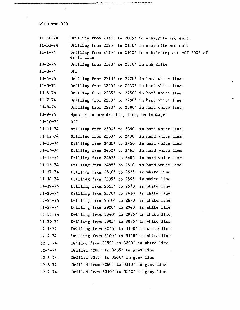
D r i l l i n g from 2035' t o 2085' i n anhydr i t e and s a l t
D r i l l i n g from 2085' t o 2150' i n anhydr i te and s a l t
D r i l l i n g from 2150' t o 2160' i n anhydr i te ; cut of f 200' of d r i l l l i n e
D r i l l i n g from 2160' t o 2210' i n anhydr i te
Off
D r i l l i n g from 2210' t o 2220' i n hard whi te l ime
D r i l l i n g from 2220' t o 2235' i n hard white l ime
D r i l l i n g from 2235' t o 2250' i n hard whi te l ime
D r i l l i n g from 2250' t o 2280' i n hard white l ime
D r i l l i n g from 2280' t o 2300' i n hard whi te l ime
Spooled on new d r i l l i n g l i n e ; no footage
Off
D r i l l i n g from 2300' t o 2350' i n hard whi te l ime
D r i l l i n g from 2350' t o 2400' i n hard white l ime
D r i l l i n g from 2400' t o 2450' i n hard whi te l ime
D r i l l i n g from 2450' t o 2465' i n hard white l ime
D r i l l i n g from 2465' t o 2485' i n hard whi te l ime
D r i l l i n g from 2485' t o 2510' i n hard white l ime
D r i l l i n g from 2510' t o 2535' i n white l ime
D r i l l i n g from 2535' t o 2555' i n white l ime
D r i l l i n g from 2555' t o 2570' i n whi te l ime
D r i l l i n g from 2570' t o 2610' i n white l ime
D r i l l i n g from 2610' t o 2680' i n whi te l ime
D r i l l i n g from 2900' t o 2940' i n white l ime
D r i l l i n g from 2940' t o 2995' i n whi te l ime
D r i l l i n g from 2995' t o 3045' i n white l ime
D r i l l i n g from 3045' t o 3100' i n whi te l ime
D r i l l i n g from 3100' t o 3150' i n white l ime
Dr i l l ed from 3150' t o 3200' i n whi te l ime
Dr i l l ed 3200' t o 3235' i n gray lime
D r i l l e d 3235' t o 3260' i n gray l ime
D r i l l e d from 3260' t o 3310' i n gray lime
D r i l l e d from 3310' t o 3340' i n gray l ime

Dr i l l ed from 3310' t o 3315' i n . g r a y lime; d r i l l i n g s t randed sand l i n e ; t r i p t o yard f o r new sand l i n e
Pul led off o l d sand l i n e , spooled on new sand l i n e
Dr i l l ed from 3310' t o 3325' i n gray lime; c leaning out
Dr i l l ed from 3325' t o 3340' i n gray lime
D r i l l i n g magneto c u t t i n g out on r i g motor
Off , wai t ing f o r magneto f o r r i g
Put magneto on motor; d r i l l i n g salt and lime
S a l t and lime s t r e a k s
Dr i l l ed from 3425' t o 3455' anhydr i te
Dr i l l ed from 3455' t o 3485' anhydr i te
Dr i l l ed from 3485' t o 3510' anhydr i te
Dr i l l ed from 3510' t o 3530' anhydr i te i n l i m e
Dr i l l ed from 3530' t o 3545' anhydr i te i n lime
Dr i l l ed from 3545' t o 3565' anhydr i te i n lime
Dr i l l ed from 3565' t o 3565' anhydr i te i n lime
Shut down - Dr i l l ed from 3565' t o 3565' anhydr i te i n lime
D r i l l e d from 3565' t o 3580' anhydr i te i n lime
Dr i l l ed from 3580' t o 3610' anhydr i te i n lime
Dr i l l ed from 3610' t o 3635' anhydr i te i n lime
Dr i l l ed from 3635' t o 3675' anhydr i te i n s a l t
Dr i l l ed from 3675' t o 3715' anhydr i te i n s a l t
Dr i l l ed from 3715' t o 3750' anhydr i te i n s a l t
D r i l l e d from 3750' t o 3785' anhydr i te i n s a l t
Dr i l l ed from 3785' t o 3800' and 3800' t o 3825' i n anhydr i te and lime
Dr i l l ed from 3825' t o 3875' lime and anhydri te
D r i l l e d from 3875' t o 3910' lime and anhydr i te
Dr i l l ed from 3910' t o 3945' lime and anhydr i te
D r i l l e d from 3945' t o 3985' lime and anhydr i te
Dr i l l ed from 3985' t o 4020' l ime and anhydr i te
D r i l l e d from 4020' t o 4030' lime and anhydr i te
Fishing f o r d r i l l t o o l s
F ish ing f o r d r i l l t o o l s

NOTE :
Fishing f o r d r i l l t o o l s
Fishing f o r d r i l l t o o l s
Fishing f o r d r i l l t o o l s
Fishing f o r d r i l l t o o l s
Run wire l i n e
Fishing f o r w i r e l i n e
F ish ing f o r wire l i n e
Fished out 20' of wire l i n e
F ish ing f o r t o o l s
Fishing f o r t o o l s
F ish ing f o r wire t o o l s
Fishing f o r t o o l s and wire
F ish ing f o r t o o l s and wire
Fishing
Fish ing f o r t o o l s
Fishing f o r t o o l s , and wire
Fished out prong of t o rgs
Fished out t o o l s
Spliced Dorlc, l ime layed down f i s h i n g t o o l s
Cleaned out hole t o bottom; d r i l l i n g
From 4035' t o 4045' l ime gray; 4045' t o 4070' l ime black; s e t socket
From 4070' t o 4090' l ime gray
From 4090' t o 4125' l ime gray; water 4095'
From 4125' t o 4150' gray lime; logged w e l l ( h i t Delaware sand a t 4170')
S t i l l logging; r i g re leased
Cabin Baby-1 was deepened t o 4298.6' (below KB) f o r hydrologic t e s t i n g by D'Appolonia (TSC) from August 12, 1983 through September 29, 1983. A l l depths r epor t ed were from k e l l y bushing e l e v a t i o n 8.0' above ground l e v e l (GL) un les s otherwise noted.
Preparing d r i l l pad, mud p i t s ; i n s t a l l i n g equipment, pumps, tanks and piping
Rig and equipment ready f o r e n t r y

Entered hole using 4-112" OD pipe with 7-718" r o t a r y b i t . Began c i r c u l a t i n g a t 3423'; encountered smal l bridge a t 3785' ; hooked-up t o k e l l y and pumped and r o t a t e d through br idge. S t a r t ed d r i l l i n g ho le f i l l a t about 4120'.
Ci rcu la ted and advanced t o 4159'. Action of d r i l l i n g i n d i c a t e d undis turbed formation. Probably not cement plug a s pH=7.0. Pul led and s t rapped pipe. Reentered and circu- l a t e d and f i shed w i t h magnet. Magnet picked up a few metal shavings. Rigged Dresser At las and en te red hole f o r Neutron-Porosity (CN) and Gamma Ray (GR). Logs run t o 4100'. Ran 4-Arm Cal iper log. Began i n s t a l l i n g BOP. Three loads of b r i n e hauled on site.
Completed BOP i n s t a l l a t i o n . Mixed mud f o r coring. Entered h o l e and c i r c u l a t e d t o c l ean hole. Touched top of forma- t i o n a t 4159' (measured from top of k e l l y bushing). Began cor ing a f t e r c i r c u l a t i n g f o r 2 hours. Coring r a t e was about 4-5 minu te s / f t wi th 16,000 l b s . on b i t . Completed cor ing a t 4219', pul led and began t o remove core.
Core removed and racked on pad (recovery 100%). Prepared c o r e barrel f o r second run. Began coring a t 4219'. Cored 4219' t o 4279' wi th 14,000 t o 16,000 l b s weight on b i t . Removed and racked core run #2. Reentered hole and began co re run /I3 a t 4279'.
A t 4298' cor ing r a t e slowed from 2 m i n l f t t o 8-10 min l f t . D r i l l i n g f l u i d pressure increased from 500 l b s . t o 1000 l b s . Core engineer suggested b i t may be damaged o r s o f t formation may have blocked c i r c u l a t i o n . Pulled core b a r r e l and performed geophysical logs. Dresser At l a s performed compensated neutron (CN), gamma ray (GR) (4097'-21001), and 4-arm c a l i p e r logs. Review of geophysical logs showed s u f f i c i e n t dep th f o r hydrologic t e s t i n g . Rig was put on s tandby u n t i l Lynes DST equipment a r r i ved .
Rig on s tandby await ing a r r i v a l of t e s t i n g equipment. Core photographs taken i n Car l s bad o f f ice core l i b r a r y .
Rig on standby.
Rig on standby. Core was sea led and boxed i n Carlsbad of f i c e co re l i b r a r y .
Rig on s tand by. Core boxing, f i l i n g , and computer log-in forms completed i n Carlsbad o f f i c e core l i b r a r y .
S t a r t ed t o run i n borehole f o r reaming wi th 9-718" b i t . Tagged a s h e l f a t 3378'. Began c i r c u l a t i n g and added 60-65 1 bs . of sodium th iocyana te . Reamed borehole t o 3800' with 9-7/8" b i t before pu l l i ng and changing t o 9-718" b i t wi th s t a b i l i z e r s (reamers). Reentered wi th t h e new reaming assembly and 9 d r i l l c o l l a r s above t h e reaming assembly.

8-26-83 Star ted t o ream with new assembly a t 3329'. Continued reaming t o 3887 ' .
8-27 -83 Continued reaming t o 4039' u n t i l r i g was shut down f o r b r i e f maintenance. Continued reaming t o 4134' (pene t ra t ion r a t e = 2.7 min/ f t ) .
8-28-83 Continued reaming t o TD (4298.6'). Circulated hole f o r 6 hours. Changed t h e flow of t h e r e t u r n f l u i d i n t o a l t e r n a t e p i t t o lengthen the t r a v e l path t o help s e t t l e cu t t ings . Pipe was l a i d f o r t h e TCWL. D r i l l p ipe was removed from hole t o allow geophysical logging by USGS and Dresser Atlas. USGS r a n 3-am c a l i p e r log , gamma r a y log , and neutron dens i ty log.
8-29-83 USGS r a n neutron poros i ty log. BOP was r e i n s t a l l e d on hole. Dresser At las ran dual l a t e r o l o g and micro l a t e ro - log. USGS began running a sonic log. Sonic t o o l malfunc- t ioned. An acous t i c televiewer l o g was then run.
8-30-83 Received neutron poros i ty , c a l i p e r , gamma ray, and acous t i c televiewer logs from USGS. Prepared r i g f o r swabbing and t e s t i n g . Began s e t t i n g up packers. S tar ted running t o o l t o f i r s t t e s t l e v e l (4178').
8-3 1-83 Continued running pipe and s i n g l e packer i n t o hole , bottom of packer located a t 4178'. Packer would not i n f l a t e . Packer was removed and taken t o shop f o r t e s t i n g by Lynes.
9-1-83 Packer with repai red c i r c u l a t i n g valve was run down hole. Malfunction of the readout u n i t associa ted wi th the t rans- ducers mandated t r ipp ing out a t 3900'. Repaired wiring and reentered hole. C i rcu i t checked OK a t 4178', but packer would not i n f l a t e .
S tar ted t o p u l l tubing and packer because packer would not i n f l a t e . Lynes co r rec ted problem and assembly was again run down hole. J -s lo t would not catch f o r numerous at tempts.
Continued attempting t o l a t c h J - s lo t . Twisting and r a i s i n g of rods caused t h e wiring t o be pul led from t h e t rans- ducer. S tar ted t r i p p i n g out. Lynes took t o o l i n t o Hobbs f o r overhaul.
Reentered hole checking pressure sensor a t i n t e r v a l s t o a s su re t h a t i t was functioning. Tool run t o 4178'. Packer was i n f l a t e d t o 1500 p s i . Pressure s t a b i l i z e d between 2076-2077 ps i . Swabbed hole down t o 3800' water l e v e l . Shut-in t o o l opened f o r f i r s t flow period (FFL). Tool shut-in f o r FBU. Opened t o o l f o r SFL t e s t . Shut-in t o o l f o r SBU test. Swabbed tubing during shut-in. Opened t o o l f o r s lug t e s t .
Terminated s l u g t e s t a t P2 = 1788 ps ia . S tar ted swabbing operat ion. Flow measurements and water samples taken during swab l i f t s .

Swabbing was completed and swabbing equipment was removed. Lynes crew began pu l l i ng packers. Preparing f o r t e s t i n g i n zone 4138' t o 4171'.
Lynes completed DST J - too l s traddle-packer assembly. Entered hole with equipment, performing c i r c u i t t e s t s a t 320' i n t e r v a l s . Se t bottom of top packer a t 4138'. Set up swabbing equipment and swabbed t o about 4000'. ' FFL, FBU, SFL, SBU were completed and Slug t e s t was s t a r t e d .
Running s l u g test a t 4138' t e s t l e v e l .
Running s l u g t e s t a t 4138' test l e v e l .
Completed s l u g test. Began swabbing operat ion.
Continuing swabbing opera t ion . Water samples were taken. Moved t h e bottom of t h e top packer t o 4100 f e e t . F i l l e d tubing t o set packer. Began swabbing process.
Completed swabbing and FF'L, FBU, SF'L, and SBU. S t a r t ed s l u g test.
Running s l u g test.
Completed s l u g test . Began swabbing opera t ion. Swabbing assembly par ted from w i r e l i n e when i t h i t top of tube.
Tripped out of hole t o r e p a i r swabbing assembly. Packers i n f l a t e d while t r i p p i n g out of hole. Packers were d e f l a t e d us ing another swabbing t o o l t o reduce t he head on t h e packer. Lower packer was damaged as i t was pul led through the BOP. Lynes took packer t o shop f o r r e p a i r . Ba l l bar s l eeve a l s o damaged.
Repaired packers were run i n t o t h e hole. C i r c u i t checks a t va r ious l e v e l s showed a s h o r t had occurred between t h e instrument and su r f ace computer. Tool w a s pul led t o check t h e systems e l e c t r o n i c s . The c i r c u i t checked a t t he sur- f ace . S t a r t e d t r i p p i n g i n . Bottom of top packer set a t 4044'. Commenced swabbing operat ion. Opened t o o l f o r FFL.
Closed t o o l f o r FBU. Continued FBU.
Continued FBU . Terminated FBU. Tripped out of hole. Tripped i n t o hole t o set packers f o r series of DST tests i n Salado Formation. Bottom packer (b r idge plug, PIP) wi th D i g i t a l Memory Recorder (DMR) 312 suspended below, set a t 2725'.
Tripped out of hole. Tripped i n and i n f l a t e d upper packer a t 735'. Upper packer did no t completely s e a t . Upper packer was moved t o 765' and set. Began swabbing ope ra t i on and DST-765 (765' l e v e l ) Salado t e s t i n g FFL, FBU, SFL, and SBU . Continued SBU (DST-765).
Swabbed tubing. Terminated SBU (DST-765) and s t a r t e d s l u g test.

9-23-83 Slug t e s t terminated. Lower and upper packers and DMR r e t r i e v e d .
9-24- 83 Sperry Sun performed d i r e c t i o n a l survey. Tripped i n and s e t packer (4039') f o r Be l l Canyon Formation H20 q u a l i t y sampling. Began swabbing operat ion. Damaged w i r e l i n e while e n t e r i n g hole f o r swabbing. Repaired w i r e l i n e and continued swabbing.
9-25-83 Continued swabbing opera t ion . Wirel ine parted from swab- bing assembly and dropped t o bottom. Pulled tubing and packer t o r e p a i r . Lynes repa i red assembly. Packer run back i n t o hole. Packer could not be i n f l a t e d a s s i n k e r bar s t i l l i n tubing. Pul led tubing and packer.
9-26-83 Repaired assembly and t r ipped i n t o hole. Se t PIP 4041' below KB. Began swabbing opera t ion (obtained samples).
9-27-83 Obtained samples and terminated swabbing (sodium th iocyanate = 1.9 mg/l).
9-28-83 Welded and completed we l l head assembly and tubing cap. Began demobil izat ion.
9-29-83 Packed and shipped samples t o lab . Completed demobili- za t ion .

DISTRIBUTION

DISTRIBUTION
U.S. Department of Energy, Headquarters Of f i ce of Nuclear Waste Management Washington, D.C. 20545
Lawrence Harmon, Program Manager (WIPP) Wade Bal la rd , Di rec tor , Div. of Waste I s o l a t i o n (2)
U.S. Department of Energy, Headquarters Off i c e of Defense Waste & By-Products Washington, D.C. 20545
D r . Goetz Oer t e l , Di rec tor (NE-320)
U.S. Department of Energy, Albuquerque Operations P.O. Box 5400 Albuquerque, New Mexico 87185
J. M. McGough, Manager, WIPP Pro jec t Off ice (2) D. Jackson, D i r ec to r , Publ ic Af fa i r s Division
U.S. Department of Energy Carlsbad WIPP Pro jec t Off i c e Room 113, Federa l Bui lding Carlsbad, New Mexico 88220
U.S. Department of Energy c /o Battelle Off ice of Nuclear Waste I s o l a t i o n 505 King Avenue Columbus, Ohio 43201
J e f f 0. Neff
B a t t e l l e Memorial I n s t i t u t e Off ice of Nuclear Waste I s o l a t i o n 505 King Avenue Columbus, Ohio 43201
S. Goldsmith, Manager ONWI L ibrary
Battelle Memorial I n s t i t u t e Pro jec t Management Div is ion 505 King Avenue Columbus, Ohio 43201
Neal C a r t e r , General Manager

DISTRIBUTION (Continued)
DIAppolonia Consulting Engineers 2340 Alamo, S.E. Albuquerque, New Mexico 87106
D. K. Shukla (25) J. K. Regis ter , f o r DOE/TIC (25)
Westinghouse E l e c t r i c Corporation P.O. Box 40039 Albuquerque, New Mexico 87196
G. L. Hohmann (15)
Bechtel National , Inc. F i f t y Beale S t r e e t P.O. Box 3965 San Francisco, Ca l i fo rn ia 94119
D. L. Ledbetter Dale Roberts
National Academy of Sciences, WIPP Panel
Frank L. Parker, Chairman Department of Environmental and Water Resources
Engineering Vanderbilt Universi ty Nashvil le , Tennessee 37235
Konrad B. Krauskopf, Vice Chairman Department of Geology Stanford Universi ty Stanford, Ca l i fo rn ia 94305
Karl P. Cohen, Member Consu 1 t a n t 928 North Ca l i fo rn ia Avenue Palo Alto, Ca l i fo rn ia 94303
Nevi l le G. W. Cook, Member Dept. of Mater ia l Sciences and Engineering Universi ty of Ca l i fo rn ia a t Berkeley Hearst Mining Building, 1320 Berkeley, Ca l i fo rn ia 94720
Fred M. Ernsberger, Member 250 Old M i l l Road Pi t t sburgh, Pennsylvania 15238

DISTRIBUTION (Continued)
National Academy of Sciences, WIPP Panel (Continued)
Richard R. . ~ a r i z e k , Member Department of Hydrogeology Pennsylvania S t a t e Universi ty Universi ty Park, Pennsylvania 16802
DIArcy A. Shock, Member 233 Virgin ia Ponca Ci ty , Oklahoma 74601
John W. Winchester, Member Department of Oceanography Flor ida S t a t e Universi ty Tal lahassee , F lor ida 32306
John T. Holloway Senior S taf f Off icer National Academy of Sciences 2101 Const i tu t ion Avenue, NW Washington, D.C. 20418
WIPP Publ ic Reading Room Atomic Museum, Kir t land East AFB Albuquerque, New Mexico 87185
Attent ion: M s . Gwynn Schreiner
WIPP Public Reading Room Carlsbad Municipal Library 101 S. Hallagueno S t r e e t Carlsbad, New Mexico 88220
Attent ion: Lee Hubbard, Head Librar ian
Thomas Brannigan Library 106 West Hadley S t r e e t Las Cruces, New Mexico 88001
Attent ion: Don Dresp, Head Librar ian
Roswell Publ ic Library 301 North Pennsylvania Avenue Roswell, N e w Mexico 88201
Attent ion: Ms. Nancy Langston
Hobbs Publ ic Library 509 North Ship S t r e e t Hobbs, New Mexico 88248
M s . Marcia Lewis. Librar ian

DISTRIBUTION (Continued)
S t a t e of New Mexico Environmental Evaluation Group 320 Marcy street P.O. Box 968 Santa Fe, New Mexico 87503
Robert H. N e i l l , Director (2)
New Mexico Department of ' ~ n e r ~ ~ & Minerals P.O. Box 2770 Santa Fe, New Mexico 87501
P. Biderman, Secretary Kasey LaPlante, Librar ian
New Mexico S t a t e Geologist P.O. Box 2860 Santa Fe, New Mexico 87501
Emery C. Arnold
New Mexico S t a t e Library P.O. Box 1629 Santa Fe, New Mexico 87503
M s . Ingr id Vollenhofer
New Mexico Tech Martin Speer Memorial Library Campus S t r e e t Socorro, New Mexico 87801
Zimmerman Library Universi ty of New Mexico Albuquerque, New Mexico 87131
M s . Vivian Zanier
USGS, Water Resources Division 505 Marquette, NW Western Bank Building Albuquerque, New Mexico 87102
J. W. Mercer (2)
USGS, Conservation Division P.O. Box 1857 Roswell, New Mexico 88201
W. Melton

DISTRIBUTION (Continued)
USGS, Special Projects Branch Denver Federal Center Mail Stop 954, Box 25046 Denver, Colorado 80225
R. P. Snyder (2)
New Mexico Bureau of Mines and Mineral Resources Socorro, New Mexico 87801
F. E. Kottlowski, Director (2)
Klaus Kuhn Gesellschaft fuer Strahlen-und Umweltforschung MBH Muenchen Institut fuer Tieflagerung Berliner Strasse 2 3392 Clausthal-Zellerfeld Federal Republic of Germany
Klaus Echart Maass Hahn-Meitner-Institut fuer Kernforschung Glienicker Strasse 100 1000 Berlin 39 Federal Republic of Germany
Michael Langer Bundesanstalt fuer Geowissenschaften und Rohstoffe Postfach 510 153 3000 Hannover 51 Federal Republic of Germany
Helmut Rot hemeyer Physikalisch-Technische Bundesanstalt Bundesalle 100 3300 Braunschweig Federal Republic of Germany
Rolf-Peter Randl Bundesministerium fuer Forschung und Technologie Postfach 200 706 5300 Bonn 2 Federal Republic of Germany
Gayle Pawloski, L-222 Geologist CSDP Lawrence Livermore Laboratory Livermore, California 94550

DISTRIBUTION (Continued)
U.S. Nuclear Regulatory Commission (3) Division of Waste Management Mail Stop 69755 Washington, D.C. 20555
Attention: J. Martin, M. Bell, H. Miller
Sandia National Laboratories Albuquerque, New Mexico 87185
9730 W. D. Weart (15)