washington state energy code residential 2018 …
TRANSCRIPT

WASHINGTON STATE ENERGY CODE - RESIDENTIAL
2018 EDITION
CHAPTER 51-11C WAC
WASHINGTON STATE BUILDING CODE COUNCIL
EFFECTIVE JULY 1, 2020
ii 2015 Washington State Energy Code
Copies of the State Building Codes and complete copies of the 2018 Model Codes
may be obtained from:
Washington Association of Building Officials Post Office Box 7310
Olympia, Washington 98507-7310 (360) 628-8669 www.wabobookstore.org
First Edition 2018 Washington State Energy Code-Residential
Effective July 1, 2020 Printed February 2020
First Edition based on
WSR 20-01-047
Chapter 51-11R WAC

2018 Washington State Energy Code iii
Chapter 51-11R WAC
2018 WASHINGTON STATE ENERGY CODE, RESIDENTIAL PROVISIONS
TABLE OF CONTENTS
Chapter 1 Scope and Administration ........................... RE-1
R101 Scope and General Requirements ................................. RE-1
R102 Alternate Materials—Method of Construction, Design or Insulating Systems ......................... RE-1
R103 Construction Documents ................... RE-2
R104 Inspections ........................................ RE-3
R105 Validity ............................................... RE-4
R106 Referenced Standards ....................... RE-4
R107 Fees .................................................. RE-4
R108 Stop Work Order ................................ RE-5
R109 Board of Appeals ............................... RE-5
R110 Violations ........................................... RE-5
R111 Liability .............................................. RE-5
Chapter 2 Definitions ............................... RE-7
R201 General .............................................. RE-7
R202 General Definitions ............................ RE-7
Chapter 3 General Requirements .......... RE-13
R301 Climate Zones ................................. RE-13
TABLE R301.1 Climate Zones ............... RE-13
R302 Design Conditions ........................... RE-14
R303 Materials, Systems and Equipment ............................. RE-14
TABLE R303.1.3(1) Default Glazed
Window, Glass Door and Skylight U-factors ...................... RE-15
TABLE R303.1.3(2) Default Opaque
Door U-factors .......................... RE-16
TABLE R303.1.3(3) Default Glazed
Fenestration SHGC & VT ........... RE-16
TABLE R303.1.3(4) Default U-factors for
Skylights ................................... RE-17
TABLE R303.1.3(5) Small Business
Compliance Table ..................... RE-18
Chapter 4 Residential Energy Efficiency ............................... RE-19
R401 General ............................................ RE-19
R402 Building Envelope ............................ RE-19
TABLE R402.1.1 Insulation and Fenestration
Requirements by Component ...... RE-20
TABLE R402.1.3 Equivalent U-factors ..... RE-21
EQUATION 1: Group R Occupancy
Target UA .....................................RE 22
EQUATION 2: Group R Occupancy
Proposed UA ................................ RE-23
TABLE R402.4.1.1 Air Barrier and Insulation
Installation ................................... RE-26
R403 Systems ........................................... RE-29
TABLE R403.6.1 Mechanical Ventilation
System Fan Efficacy ................... RE-33
R404 Electrical Power and Lighting Systems .......................... RE-34
R405 Simulated Performance Alternative .................................... RE-34
TABLE R405. 2 Mandatory Compliance
Measures for Simulated Performance Alternative ............. RE-35
TABLE R405.3 Carbon Emissions
Factors ..................................... RE-35
TABLE R405.5.2(1) Specifications for the
Standard Reference and Proposed Designs ..................... RE-37
TABLE R405.5.2(2) Default Distribution
System Efficiencies for Proposed Design ....................... RE-40
R406 Additional Energy Efficiency Requirements ............................... RE-41
TABLE R406.2 Fuel Normalization
Credits ...................................... RE-41
TABLE R406.3 Energy Credits ............... RE-42
R407 Certified Passive House ................... RE-49
Chapter 5 Existing Buildings ................ RE-51
R501 General ............................................ RE-51
R502 Additions .......................................... RE-52
R503 Alterations ........................................ RE-52
R504 Repairs ............................................ RE-54
R505 Change of Occupancy or Use .......... RE-54
Chapter 6 Referenced Standards ......... RE-55
iv 2018 Washington State Energy Code
2018 WASHINGTON STATE ENERGY CODE, RESIDENTIAL APPENDIX CHAPTERS
TABLE OF CONTENTS
Appendix A Default Heat Loss Coefficients .......................... RE-59
A101 General ...................................... RE-59
A102 Ceilings ...................................... RE-61
A103 Above Grade Walls ................... RE-68
A104 Below Grade Walls and Slabs ............................... RE-84
A105 Floors Over Unconditioned Space ............. RE-86
A106 On-Grade Slab Floors ............... RE-87
A107 Default U-Factors for Doors ...... RE-88
A108 Air Infiltration ............................. RE-92
Appendix RA/RB Optional Energy Efficiency Measures ... RE-93
App RA One Step ....................... RE-93
App RB Two Step ....................... RE-93
Appendix C Exterior Design Conditions.......................... RE-95

2018 Washington State Energy Code v
Margin Markings
►
>
.
.
*
**
Indicates where a section has been deleted from the requirements of the 2015 IECC Indicates 2018 IECC language deleted by Washington state amendment
Indicates a change from the requirements of the 2015 IECC in the model code
Indicates a Washington state amendment to the 2018 IECC (but remains unchanged fro the 2015 WSEC language) Indicates a change from the 2015 Washington state amendment
Indicates that text or table has been relocated within the code Indicates the text or table immediately following has been
relocated there from elsewhere
in the code.

2018 Washington State Energy Code RE-1
CHAPTER 1 [RE]
SCOPE AND ADMINISTRATION
SECTION R101
SCOPE AND GENERAL REQUIREMENTS
R101.1 Title. This code shall be known as the Washington State Energy Code-Residential, and shall be
cited as such. It is referred to herein as "this code."
R101.2 Scope. This code applies to residential buildings and the buildings sites and associated systems
and equipment. This code shall be the maximum and minimum energy code for residential construction in
each town, city and county. Residential sleeping units, Group I-1, Condition 2 assisted living facilities
licensed by Washington state under chapter 388-78A WAC and Group I-1, Condition 2 residential
treatment facilities licensed by Washington state under chapter 246-337 WAC shall utilize the commercial
building sections of the energy code regardless of the number of stories of height above grade plane.
R101.3 Intent. This code shall regulate the design and construction of buildings for the effective use and
conservation of energy over the useful life of each building. This code is intended to provide flexibility to
permit the use of innovative approaches and techniques to achieve this objective. This code is not
intended to abridge safety, health or environmental requirements contained in other applicable codes or
ordinances.
R101.4 Applicability. Where, in any specific case, different sections of this code specify different
materials, methods of construction or other requirements, the most restrictive shall govern. Where there is
a conflict between a general requirement and a specific requirement, the specific requirement shall
govern.
R101.4.1 Mixed residential and commercial buildings. Where a building includes both residential
building and commercial building portions, each portion shall be separately considered and meet the
applicable provisions of the WSEC - Commercial Provisions or WSEC - Residential Provisions.
R101.5 Compliance. Residential buildings shall meet the provisions of WSEC - Residential Provisions.
Commercial buildings shall meet the provisions of WSEC - Commercial Provisions.
R101.5.1 Compliance materials. The code official shall be permitted to approve specific computer
software, worksheets, compliance manuals and other similar materials that meet the intent of this code.
SECTION R102 ALTERNATIVE MATERIALS, DESIGN AND METHODS
OF CONSTRUCTION AND EQUIPMENT
R102.1 General. The provisions of this code are not intended to prevent the installation of any material or
to prohibit any design or method of construction not specifically prescribed by this code. The code official
shall have the authority to approve an alternate material, design or method of construction upon
application of the owner or the owner’s authorized agent. The code official shall first find that the
proposed design is satisfactory and complies with the intent of the provisions of this code, and that the
material, method or work offered is, for the purpose intended, not less than the equivalent of that
prescribed in this code for strength, effectiveness, fire resistance, durability and safety. Where the
alternative material, design or method of construction is not approved, the code official shall respond in
writing, stating the reasons why the alternative was not approved.
RE-2 2018 Washington State Energy Code
SECTION R103 CONSTRUCTION DOCUMENTS
R103.1 General. Construction documents, technical reports, and other supporting data shall be submitted
in one or more sets with each application for a permit. The construction documents and technical reports
shall be prepared by a registered design professional where required by the statutes of the jurisdiction in
which the project is to be constructed. Where special conditions exist, the code official is authorized to
require necessary construction documents to be prepared by a registered design professional.
Exception: The code official is authorized to waive the requirements for construction documents or
other supporting data if the code official determines they are not necessary to confirm compliance with
this code.
R103.2 Information on construction documents. Construction documents shall be drawn to scale upon
suitable material. Electronic media documents are permitted to be submitted when approved by the code
official. Construction documents shall be of sufficient clarity to indicate the location, nature and extent of
the work proposed, and show in sufficient detail pertinent data and features of the building, systems and
equipment as herein governed. Details shall include, but are not limited to, the following as applicable:
1. Insulation materials and their R-values.
2. Fenestration U-factors and SHGCs.
3. Area-weighted U-factor and SHGC calculations.
4. Mechanical system design criteria.
5. Mechanical and service water heating system and equipment types, sizes and efficiencies.
6. Equipment and systems controls
7. Duct sealing, duct and pipe insulation and location.
8. Air sealing details.
R103.2.1 Building thermal envelope depiction. The building’s thermal envelope shall be represented
on the construction documents.
R103.3 Examination of documents. The code official shall examine or cause to be examined the
accompanying construction documents and shall ascertain whether the construction indicated and
described is in accordance with the requirements of this code and other pertinent laws or ordinances. The
code official is authorized to utilize a registered design professional or other approved entity not affiliated
with the building design or construction in conducting the review of the plans and specifications for
compliance with the code.
R103.3.1 Approval of construction documents. When the code official issues a permit where
construction documents are required, the construction documents shall be endorsed in writing and
stamped "Reviewed for Code Compliance." Such approved construction documents shall not be
changed, modified or altered without authorization from the code official. Work shall be done in
accordance with the approved construction documents.
One set of construction documents so reviewed shall be retained by the code official. The other set
shall be returned to the applicant, kept at the site of work and shall be open to inspection by the code
official or a duly authorized representative.
R103.3.2 Previous approvals. This code shall not require changes in the construction documents,
construction or designated occupancy of a structure for which a lawful permit has been heretofore
issued or otherwise lawfully authorized, and the construction of which has been pursued in good faith
within 180 days after the effective date of this code and has not been abandoned.
R103.3.3 Phased approval. The code official shall have the authority to issue a permit for the
construction of part of an energy conservation system before the construction documents for the entire
system have been submitted or approved, provided adequate information and detailed statements have
been filed complying with all pertinent requirements of this code. The holders of such permit shall
proceed at their own risk without assurance that the permit for the entire energy conservation system
will be granted.

2018 Washington State Energy Code RE-3
R103.4 Amended construction documents. Work shall be installed in accordance with the approved
construction documents, and any changes made during construction that are not in compliance with the
approved construction documents shall be resubmitted for approval as an amended set of construction
documents.
R103.5 Retention of construction documents. One set of approved construction documents shall be
retained by the code official for a period of not less than 180 days from date of completion of the
permitted work, or as required by state or local laws.
SECTION R104 INSPECTIONS
R104.1 General. Construction or work for which a permit is required shall be subject to inspection by the
code official or his or her designated agent, and such construction or work shall remain visible and able to
be accessed for inspection purposes until approved. It shall be the duty of the permit applicant to cause
the work to remain visible and able to be accessed for inspection purposes. Neither the code official nor
the jurisdiction shall be liable for expense entailed in the removal or replacement of any material, product,
system or building component required to allow inspection to validate compliance with this code.
R104.2 Required inspections. The code official or his or her designated agent, upon notification, shall
make the inspections set forth in Sections R104.2.1 through R104.2.5.
R104.2.1 Footing and foundation inspection. Inspections associated with footings and foundations
shall verify compliance with the code as to R-value, location, thickness, depth of burial and protection of
insulation as required by the code and approved plans and specifications.
R104.2.2 Framing and rough-in inspection. Inspections at framing and rough-in shall be made before
application of interior finish and shall verify compliance with the code as to types of insulation and
corresponding R-values and their correct location and proper installation; fenestration properties (U-
factor and SHCG) and proper installation; and air leakage controls as required by the code and
approved plans and specifications.
R104.2.2.1 Wall insulation inspection. The building official, upon notification, shall make a wall
insulation inspection in addition to those inspections required in Section R109 of the International
Residential Code. This inspection shall be made after all wall and cavity insulation is in place and
prior to cover.
C104.2.3 Plumbing rough-in inspection. Inspections at plumbing rough-in shall verify compliance as
required by the code and approved plans and specifications as to types of insulation and corresponding
R-values and protection, and required controls.
C104.2.4 Mechanical rough-in inspection. Inspections at mechanical rough-in shall verity compliance
as required by the code and approved plans and specifications as to installed HVAC equipment type
and size, required controls, system insulation and corresponding R-value, system air leakage control,
programmable thermostats, dampers, whole-house ventilation and minimum fan efficiency.
Exception: Systems serving multiple dwelling units shall be inspected in accordance with Section
C104.2.4.
R104.2.5 Final inspection. The building shall have a final inspection and not be occupied until
approved.
R104.3 Reinspection. A building shall be reinspected when determined necessary by the code official.
R104.4 Approved inspection agencies. The code official is authorized to accept reports of third-party
inspection agencies not affiliated with the building design or construction, provided such agencies are
approved as to qualifications and reliability relevant to the building components and systems they are
inspecting.
R104.5 Inspection requests. It shall be the duty of the holder of the permit or their duly authorized agent
to notify the code official when work is ready for inspection. It shall be the duty of the permit holder to
provide access to and means for inspections of such work that are required by this code.

RE-4 2018 Washington State Energy Code
R104.6 Reinspection and testing. Where any work or installation does not pass an initial test or
inspection, the necessary corrections shall be made so as to achieve compliance with this code. The
work or installation shall then be resubmitted to the code official for inspection and testing.
R104.7 Approval. After the prescribed tests and inspections indicate that the work complies in all
respects with this code, a notice of approval shall be issued by the code official.
R104.7.1 Revocation. The code official is authorized to, in writing, suspend or revoke a notice of
approval issued under the provisions of this code wherever the certificate is issued in error, or on the
basis of incorrect information supplied, or where it is determined that the building or structure, premise,
or portion thereof is in violation of any ordinance or regulation or any of the provisions of this code.
SECTION R105 VALIDITY
R105.1 General. If a portion of this code is held to be illegal or void, such a decision shall not affect the
validity of the remainder of this code.
SECTION R106 REFERENCED STANDARDS
R106.1 Referenced codes and standards. The codes and standards referenced in this code shall be
those listed in Chapter 5, and such codes and standards shall be considered as part of the requirements
of this code to the prescribed extent of each such reference and as further regulated in Sections R106.1.1
and R106.1.2.
R106.1.1 Conflicts. Where differences occur between provisions of this code and referenced codes and
standards, the provisions of this code shall apply.
R106.1.2 Provisions in referenced codes and standards. Where the extent of the reference to a
referenced code or standard includes subject matter that is within the scope of this code, the provisions of
this code, as applicable, shall take precedence over the provisions in the referenced code or standard.
R106.2 Application of references. References to chapter or section numbers, or to provisions not
specifically identified by number, shall be construed to refer to such chapter, section or provision of this
code.
R106.3 Other laws. The provisions of this code shall not be deemed to nullify any provisions of local,
state or federal law. In addition to the requirements of this code, all occupancies shall conform to the
provisions included in the state building code (chapter 19.27 RCW). In case of conflicts among codes
enumerated in RCW 19.27.031 (1) through (4) and this code, an earlier named code shall govern over
those following. In the case of conflict between the duct sealing and insulation requirements of this code
and the duct insulation requirements of Sections 603 and 604 of the International Mechanical Code, the
duct insulation requirements of this code shall govern.
SECTION R107 FEES
R107.1 Fees. A permit shall not be issued until the fees prescribed in Section R107.2 have been paid,
nor shall an amendment to a permit be released until the additional fee, if any, has been paid.
R107.2 Schedule of permit fees. A fee for each permit shall be paid as required, in accordance with the
schedule as established by the applicable governing authority.
R107.3 Work commencing before permit issuance. Any person who commences any work before
obtaining the necessary permits shall be subject to an additional fee established by the code official,
which shall be in addition to the required permit fees.
R107.4 Related fees. The payment of the fee for the construction, alteration, removal or demolition of
work done in connection to or concurrently with the work or activity authorized by a permit shall not
relieve the applicant or holder of the permit from the payment of other fees that are prescribed by law.
R107.5 Refunds. The code official is authorized to establish a refund policy.

2018 Washington State Energy Code RE-5
SECTION R108 STOP WORK ORDER
R108.1 Authority. Whenever the code official finds any work regulated by this code being performed in a
manner either contrary to the provisions of this code or dangerous or unsafe, the code official is
authorized to issue a stop work order.
R108.2 Issuance. The stop work order shall be in writing and shall be given to the owner of the property
involved, or to the owner's authorized agent, or to the person doing the work. Upon issuance of a stop
work order, the cited work shall immediately cease. The stop work order shall state the reason for the
order, and the conditions under which the cited work will be permitted to resume.
R108.3 Emergencies. Where an emergency exists, the code official shall not be required to give a
written notice prior to stopping the work.
R108.4 Failure to comply. Any person who shall continue any work after having been served with a stop
work order, except such work as that person is directed to perform to remove a violation or unsafe
condition, shall be subject to a fine as set by the applicable governing authority.
SECTION R109 BOARD OF APPEALS
R109.1 General. In order to hear and decide appeals of orders, decisions or determinations made by the
code official relative to the application and interpretation of this code, there shall be and is hereby created
a board of appeals. The code official shall be an ex officio member of said board but shall have no vote
on any matter before the board. The board of appeals shall be appointed by the governing body and shall
hold office at its pleasure. The board shall adopt rules of procedure for conducting its business, and shall
render all decisions and findings in writing to the appellant with a duplicate copy to the code official.
R109.2 Limitations on authority. An application for appeal shall be based on a claim that the true intent
of this code or the rules legally adopted thereunder have been incorrectly interpreted, the provisions of
this code do not fully apply or an equally good or better form of construction is proposed. The board shall
have no authority to waive requirements of this code.
R109.3 Qualifications. The board of appeals shall consist of members who are qualified by experience
and training and are not employees of the jurisdiction.
SECTION R110 VIOLATIONS
It shall be unlawful for any person, firm, or corporation to erect or construct any building, or remodel or
rehabilitate any existing building or structure in the state, or allow the same to be done, contrary to or in
violation of any of the provisions of this code.
SECTION R111 LIABILITY
Nothing contained in this code is intended to be nor shall be construed to create or form the basis for any
liability on the part of any city or county or its officers, employees or agents for any injury or damage
resulting from the failure of a building to conform to the provisions of this code.

RE-6 2018 Washington State Energy Code
2018 Washington State Energy Code RE-7
◄
CHAPTER 2 [RE]
DEFINITIONS
SECTION R201 GENERAL
R201.1 Scope. Unless stated otherwise, the following words and terms in this code shall have the
meanings indicated in this chapter.
R201.2 Interchangeability. Words used in the present tense include the future; words in the masculine
gender include the feminine and neuter; the singular number includes the plural and the plural includes
the singular.
R201.3 Terms defined in other codes. Terms that are not defined in this code but are defined in the
International Building Code, International Fire Code, International Fuel Gas Code, International
Mechanical Code, Uniform Plumbing Code or the International Residential Code shall have the meanings
ascribed to them in those codes.
R201.4 Terms not defined. Terms not defined by this chapter shall have ordinarily accepted meanings
such as the context implies.
SECTION R202 GENERAL DEFINITIONS
ABOVE-GRADE WALL. A wall enclosing conditioned space that is not a below-grade wall. This includes
between-floor spandrels, peripheral edges of floors, roof and basement knee walls, dormer walls, gable
end walls, walls enclosing a mansard roof and skylight shafts.
ACCESSIBLE. Admitting close approach as a result of not being guarded by locked doors, elevation or other
effective means (see "Readily accessible").
ADDITION. An extension or increase in the conditioned space floor area, number of stories, or height of a
building or structure.
ADVANCED FRAMED WALLS. Studs framed on 24-inch centers with double top plate and single bottom plate.
Corners use two studs or other means of fully insulating corners, and one stud is used to support each
header. Headers consist of double 2x material with R-10 insulation between the header and exterior
sheathing. Interior partition wall/exterior wall intersections are fully insulated in the exterior wall. (See
Standard Framing and Appendix A, of this code.)
AIR BARRIER. One or more materials joined together in a continuous manner to restrict or prevent the
passage of air through the building thermal envelope and its assemblies.
AIR-IMPERMEABLE INSULATION. An insulation that functions as an air barrier material.
ALTERATION. Any construction, retrofit or renovation to an existing structure other than repair or addition.
Also, a change in a building, electrical, gas, mechanical or plumbing system that involves an extension,
addition or change to the arrangement, type or purpose of the original installation.
APPROVED. Acceptable to the code official.
APPROVED AGENCY. An established and recognized agency that is regularly engaged in conducting tests or
furnishing inspection services, or furnishing product certification, where such agency has been approved
by the code official.

RE-8 2018 Washington State Energy Code
<
AUTOMATIC. Self-acting, operating by its own mechanism when actuated by some impersonal influence,
as, for example, a change in current strength, pressure, temperature or mechanical configuration (see
"Manual").
BASEMENT WALL. See above-grade wall and below-grade wall.
BELOW-GRADE WALL. That portion of a wall in the building envelope that is entirely below the finish grade
and in contact with the ground.
BUILDING. Any structure used or intended for supporting or sheltering any use or occupancy, including any
mechanical systems, service water heating systems and electric power and lighting systems located on
the building site and supporting the building.
BUILDING SITE. A contiguous area of land that is under the ownership or control of one entity.
BUILDING THERMAL ENVELOPE. The below-grade walls, above-grade walls, floors, ceiling, roofs, and any
other building element assemblies that enclose conditioned space or provide a boundary between
conditioned space and exempt or unconditioned space.
C-FACTOR (THERMAL CONDUCTANCE). The coefficient of heat transmission (surface to surface) through a
building component or assembly, equal to the time rate of heat flow per unit area and the unit temperature
difference between the warm side and cold side surfaces (Btu/h ft2 × °F) [W/(m2 × K)].
CIRCULATING HOT WATER SYSTEM. A specifically designed water distribution system where one or more
pumps are operated in the service hot water piping to circulate heated water from the water-heating
equipment to the fixture supply and back to the water-heating equipment.
CLIMATE ZONE. A geographical region based on climatic criteria as specified in this code.
CODE OFFICIAL. The officer or other designated authority charged with the administration and enforcement
of this code, or a duly authorized representative.
COMMERCIAL BUILDING. For this code, all buildings that are not included in the definition of "Residential
buildings."
CONDITIONED FLOOR AREA. The horizontal projection of the floors associated with the conditioned space.
CONDITIONED SPACE. An area, room or space that is enclosed within the building thermal envelope and
that is directly or indirectly heated or cooled. Spaces are indirectly heated or cooled where they
communicate through openings with conditioned spaced, where they are separated from conditioned
spaces by uninsulated walls, floors or ceilings, or where they contain uninsulated ducts, piping or other
sources of heating or cooling.
CONNECTED THERMOSTAT. An internet enabled device that automatically adjusts heating and cooling
temperature settings.
CONTINUOUS AIR BARRIER. A combination of materials and assemblies that restrict or prevent the passage
of air through the building thermal envelope.
CONTINUOUS INSULATION (c.i.). Insulating material that is continuous across all structural members without
thermal bridges other than fasteners and service openings. It is installed on the interior or exterior or is
integral to any opaque surface of the building envelope.
CURTAIN WALL. Fenestration products used to create an external nonload-bearing wall that is designed to
separate the exterior and interior environments.
DEMAND RECIRCULATION WATER SYSTEM. A water distribution system having one or more recirculation
pumps that pump water from a heated water supply pipe back to the heated water source through a cold
water supply pipe.
DUCT. A tube or conduit utilized for conveying air. The air passages of self-contained systems are not to
be construed as air ducts.
DUCT SYSTEM. A continuous passageway for the transmission of air that, in addition to ducts, includes duct
fittings, dampers, plenums, fans and accessory air-handling equipment and appliances.

2018 Washington State Energy Code RE-9
DUCTLESS MINI-SPLIT HEAT PUMP SYSTEM. A heating and cooling system that is comprised of one or multiple
indoor evaporator/air-handling units and an outdoor condensing unit that is connected by refrigerant
piping and electrical wiring. A ductless mini-split system is capable of cooling or heating one or more
rooms without the use of a central ductwork system.
DWELLING UNIT. A single unit providing complete independent living facilities for one or more persons,
including permanent provisions for living, sleeping, eating, cooking and sanitation.
ENERGY ANALYSIS. A method for estimating the annual energy use of the proposed design and standard
reference design based on estimates of energy use.
ENERGY COST. The total estimated annual cost for purchased energy for the building functions regulated
by this code, including applicable demand charges.
ENERGY SIMULATION TOOL. An approved software program or calculation-based methodology that projects
the annual energy use of a building.
EXTERIOR WALL. Walls including both above-grade walls and below-grade walls.
FENESTRATION. Products classified as either vertical fenestration or skylights.
VERTICAL FENESTRATION. Windows (fixed or operable), glazed doors, glazed block and combination
opaque/glazed doors composed of glass or other transparent or translucent glazing materials and
installed at a slope of not less than 60 degrees from horizontal. Opaque areas such as spandrel panels
are not considered vertical fenestration.
SKYLIGHT. Glass or other transparent or translucent glazing material installed at a slope of less than 60
degrees from horizontal.
FENESTRATION AREA. Total area of the fenestration measured using the rough opening, and including the
glazing, sash and frame.
FENESTRATION PRODUCT, FIELD-FABRICATED. A fenestration product whose frame is made at the
construction site of standard dimensional lumber or other materials that were not previously cut, or
otherwise formed with the specific intention of being used to fabricate a fenestration product or exterior
door. Field fabricated does not include site-built fenestration.
FENESTRATION PRODUCT, SITE-BUILT. A fenestration designed to be made up of field-glazed or field-
assembled units using specific factory cut or otherwise factory-formed framing and glazing units.
Examples of site-built fenestration include storefront systems, curtain walls, and atrium roof systems.
F-FACTOR. The perimeter heat loss factor for slab-on-grade floors (Btu/h × ft × °F) [W/(m × K)].
HEATED SLAB-ON-GRADE FLOOR. Slab-on-grade floor construction in which the heating elements, hydronic
tubing, or hot air distribution system is in contact with, or placed within or under, the slab.
HIGH-EFFICACY LIGHT SOURCES. Fixtures that use light emitting diodes (LED), T-8 or smaller diameter linear
fluorescent lamps, or other lamps with a minimum efficacy of 65 lumens per watt.
HISTORIC BUILDINGS. Buildings that are listed in or eligible for listing in the National Register of Historic
Places, or designated as historic under an appropriate state or local law.
INFILTRATION. The uncontrolled inward air leakage into a building caused by the pressure effects of wind
or the effect of differences in the indoor and outdoor air density or both.
INSULATING SHEATHING. An insulating board with a core material having a minimum R-value of R-2.
INSULATING SIDING. A type of continuous insulation with manufacturer-installed insulating material as an
integral part of the cladding product having a minimum R-value of R-2.
INTEGRATED ENERGY EFFICIENCY RATIO (IEER). A single-number figure of merit expressing cooling part-load
EER efficiency for unitary air-conditioning and heat pump equipment on the basis of weighted operation
at various load capacities for the equipment.

RE-10 2018 Washington State Energy Code
INTERMEDIATE FRAMED WALLS. Studs framed on 16-inch centers with double top plate and single bottom
plate. Corners use two studs or other means of fully insulating corners, and each opening is framed by
two studs. Headers shall be insulated to R-10.
LABELED. Equipment, materials or products to which have been affixed a label, seal, symbol or other
identifying mark of a nationally recognized testing laboratory, approved agency or other organization
concerned with product evaluation that maintains periodic inspection of the production of the above-
labeled items and whose labeling indicates either that the equipment, material or product meets identified
standards or has been tested and found suitable for a specified purpose.
LISTED. Equipment, materials, products or services included in a list published by an organization
acceptable to the code official and concerned with evaluation of products or services that maintains
periodic inspection of production of listed equipment or materials or periodic evaluation of services and
whose listing states either that the equipment, material, product or service meets identified standards or
has been tested and found suitable for a specified purpose.
LOG STRUCTURE. A type of construction whose primary structural elements are formed by a system of logs.
LOG WALL. An assembly of individual structural logs for use as an exterior or interior load bearing wall,
shear wall or nonload bearing wall.
LOW-VOLTAGE LIGHTING. A lighting system consisting of an isolating power supply, the low voltage
luminaires, and associated equipment that are all identified for the use. The output circuits of the power
supply operate at 30 volts (42.4 volts peak) or less under all load conditions.
MANUAL. Capable of being operated by personal intervention (see "Automatic").
OPAQUE DOOR. A door that is not less than 50 percent opaque in surface area.
PILOT LIGHT, CONTINUOUSLY BURNING. A small gas flame used to ignite gas at a larger burning. Once lit, a
continuously pilot light remains in operation until manually interrupted. Pilot light ignition systems with the
ability to switch between intermittent and continuous mode are considered continuous.
PILOT LIGHT, INTERMITTENT. A pilot which is automatically ignited when an appliance is called on to operate
and which remains continuously ignited during each period of main burner operation. The pilot is
automatically extinguished when each main burner operating cycle is completed.
PILOT LIGHT, INTERRUPTED. A pilot which is automatically ignited prior to the admission of fuel to the main
burner and which is automatically extinguished after the main flame is established.
PILOT LIGHT, ON-DEMAND. A pilot which, once placed into operation, is intended to remain ignited for a
predetermined period of time following an automatic or manual operation of the main burner gas valve
PROPOSED DESIGN. A description of the proposed building used to estimate annual energy use for
determining compliance based on total building performance.
READILY ACCESSIBLE. Capable of being reached quickly for operation, renewal or inspection without
requiring those to whom ready access is requisite to climb over or remove obstacles or to resort to
portable ladders or access equipment (see "Accessible").
REPAIR. The reconstruction or renewal of any part of an existing building for the purpose of its
maintenance or to correct damage.
REROOFING. The process of recovering or replacing an existing roof covering. See “Roof recover” and
“Roof replacement.”
RESIDENTIAL BUILDING. For this code, includes detached one- and two-family dwellings, multiple single-
family dwellings (townhouses) and Group R-2, R-3 and R-4 buildings three stories or less in height above
grade plane, as well as accessory structures thereto.
ROOF ASSEMBLY. A system designed to provide weather protection and resistance to design loads. The
system consists of a roof covering and roof deck or a single component serving as both the roof covering
and the roof deck. A roof assembly includes the roof covering, underlayment and roof deck, and can also
include a thermal barrier, an ignition barrier, insulation or a vapor retarder.

2018 Washington State Energy Code RE-11
<
ROOF RECOVER. The process of installing an additional roof covering over a prepared existing roof
covering without removing the existing roof covering.
ROOF REPAIR. Reconstruction or renewal of any part of an existing roof for the purposes of its
maintenance.
ROOF REPLACEMENT. The process of removing the existing roof covering, repairing any damaged substrate
and installing a new roof covering.
R-VALUE (THERMAL RESISTANCE). The inverse of the time rate of heat flow through a body from one of its
bounding surfaces to the other surface for a unit temperature difference between the two surfaces, under
steady state conditions, per unit area (h • ft2 • °F/Btu) [(m2 • K)/W].
SERVICE WATER HEATING. Supply of hot water for purposes other than comfort heating.
SLAB-ON-GRADE FLOOR. That portion of a slab floor of the building envelope that is in contact with the
ground and that is either above grade or is less than or equal to 24 inches below the final elevation of the
nearest exterior grade.
SMALL BUSINESS. Any business entity (including a sole proprietorship, corporation, partnership or other
legal entity) which is owned and operated independently from all other businesses, which has the
purpose of making a profit, and which has fifty or fewer employees.
SOLAR HEAT GAIN COEFFICIENT (SHGC). The ratio of the solar heat gain entering the space through the
fenestration assembly to the incident solar radiation. Solar heat gain includes directly transmitted solar
heat and absorbed solar radiation which is then reradiated, conducted or convected into the space.
STANDARD FRAMING. All framing practices not defined as "intermediate" or "advanced" shall be considered
standard. (See Advanced Framed Wall, Intermediate Framed Wall).
STANDARD REFERENCE DESIGN. A version of the proposed design that meets the minimum requirements of
this code and is used to determine the maximum annual energy use requirement for compliance based
on total building performance.
THERMAL ISOLATION. Physical and space conditioning separation from conditioned space(s). The
conditioned space(s) shall be controlled as separate zones for heating and cooling or conditioned by
separate equipment.
THERMOSTAT. An automatic control device used to maintain temperature at a fixed or adjustable set point.
U-FACTOR (THERMAL TRANSMITTANCE). The coefficient of heat transmission (air to air) through a building
component or assembly, equal to the time rate of heat flow per unit area and unit temperature difference
between the warm side and cold side air films (Btu/h • ft2 • °F) [W/(m2 • K)].
UNHEATED SLAB-ON-GRADE FLOOR. A slab-on-grade floor that is not a heated slab-on-grade floor.
VENTILATION. The natural or mechanical process of supplying conditioned or unconditioned air to, or
removing such air from, any space.
VENTILATION AIR. That portion of supply air that comes from outside (outdoors) plus any recirculated air
that has been treated to maintain the desired quality of air within a designated space.
VISIBLE TRANSMITTANCE [VT]. The ratio of visible light entering the space through the fenestration product
assembly to the incident visible light, visible transmittance, includes the effects of glazing material and
frame and is expressed as a number between 0
and 1.
WHOLE HOUSE MECHANICAL VENTILATION SYSTEM. An exhaust system, supply system, or combination
thereof that is designed to mechanically exchange indoor air with outdoor air when operating continuously
or through a programmed intermittent schedule to satisfy the whole house ventilation rates.
ZONE. A space or group of spaces within a building with heating or cooling requirements that are
sufficiently similar so that desired conditions can be maintained throughout using a single controlling
device.

RE-12 2018 Washington State Energy Code

2018 Washington State Energy Code RE-13
CHAPTER 3 [RE]
GENERAL REQUIREMENTS
SECTION R301
CLIMATE ZONES
R301.1 General. Climate zones from Table R301.1 shall be used in determining the applicable
requirements from Chapter 4.
TABLE R301.1
CLIMATE ZONES, MOISTURE REGIMES, AND WARM-HUMID DESIGNATIONS
BY STATE AND COUNTY
Key: A - Moist, B - Dry, C - Marine. Absence of moisture designation indicates
moisture regime is irrelevant.
WASHINGTON
5B Adams 4C Lewis
5B Asotin 5B Lincoln
5B Benton 4C Mason
5B Chelan 5B Okanogan
4C Clallam 4C Pacific
4C Clark 5B Pend Oreille
5B Columbia 4C Pierce
4C Cowlitz 4C San Juan
5B Douglas 4C Skagit
5B Ferry 5B Skamania
5B Franklin 4C Snohomish
5B Garfield 5B Spokane
5B Grant 5B Stevens
4C Grays Harbor 4C Thurston
4C Island 4C Wahkiakum
4C Jefferson 5B Walla Walla
4C King 4C Whatcom
4C Kitsap 5B Whitman
5B Kittitas 5B Yakima
5B Klickitat

RE-14 2018 Washington State Energy Code
SECTION R302 DESIGN CONDITIONS
R302.1 Interior design conditions. The interior design temperatures used for heating and cooling load
calculations shall be a maximum of 72°F (22°C) for heating and minimum of 75°F (24°C) for cooling.
R302.2 Exterior design conditions. The heating or cooling outdoor design temperatures shall be
selected from Appendix C.
SECTION R303 MATERIALS, SYSTEMS AND EQUIPMENT
R303.1 Identification. Materials, systems and equipment shall be identified in a manner that will allow a
determination of compliance with the applicable provisions of this code.
R303.1.1 Building thermal envelope insulation. An R-value identification mark shall be applied by
the manufacturer to each piece of building thermal envelope insulation 12 inches (305 mm) or greater in
width. Alternately, the insulation installers shall provide a certification listing the type, manufacturer and
R-value of insulation installed in each element of the building thermal envelope. For blown or sprayed
insulation (fiberglass and cellulose), the initial installed thickness, settled thickness, settled R-value,
installed density, coverage area and number of bags installed shall be listed on the certification. For
sprayed polyurethane foam (SPF) insulation, the installed thickness of the areas covered and R-value
of installed thickness shall be listed on the certification. For insulated siding, the R-value shall be
labeled on the product’s package and shall be listed on the certification. The insulation installer shall
sign, date and post the certification in a conspicuous location on the job site.
Exception: For roof insulation installed above the deck, the R-value shall be labeled as required by
the material standards specified in Table 1508.2 of the International Building Code or Table R906.2 of
the International Residential Code.
R303.1.1.1 Blown or sprayed roof/ceiling insulation. The thickness of blown-in or sprayed
roof/ceiling insulation (fiberglass or cellulose) shall be written in inches (mm) on markers that are
installed at least one for every 300 square feet (28 m2) throughout the attic space. The markers shall
be affixed to the trusses or joists and marked with the minimum initial installed thickness with
numbers a minimum of 1 inch (25 mm) in height.
Each marker shall face the attic access opening. Spray polyurethane foam thickness and installed R-
value shall be listed on certification provided by the insulation installer.
R303.1.2 Insulation mark installation. Insulating materials shall be installed such that the
manufacturer's R-value mark is readily observable upon inspection.
R303.1.3 Fenestration product rating. U-factors of fenestration products (windows, doors and
skylights) shall be determined in accordance with NFRC 100.
Exception: Where required, garage door U-factors shall be determined in accordance with either
NFRC 100 or ANSI/DASMA 105.
U-factors shall be determined by an accredited, independent laboratory, and labeled and certified by
the manufacturer. Products lacking such a labeled U-factor shall be assigned a default U-factor from
Table R303.1.3(1), R303.1.3(2) or R303.1.3(4). The solar heat gain coefficient (SHGC) and visible
transmittance (VT) of glazed fenestration products (windows, glazed doors and skylights) shall be
determined in accordance with NFRC 200 by an accredited, independent laboratory, and labeled and
certified by the manufacturer. Products lacking such a labeled SHGC or VT shall be assigned a default
SHGC or VT from Table R303.1.3(3).
Exceptions:
1. Units without NFRC ratings produced by a small business may be assigned default U-factors
from Table R303.1.3(5) for vertical fenestration.
2. Owner-built, nonoperable wood frame window consisting of a double pane unit with low-e
(E=0.04 or less), ½-inch airspace with argon fill.

2018 Washington State Energy Code RE-15
TABLE R303.1.3(1) DEFAULT GLAZED WINDOW, GLASS DOOR AND SKYLIGHT U-FACTOR
FRAME TYPE
WINDOW AND GLASS DOOR
SKYLIGHT SINGLE PANE
DOUBLE PANE
Metal 1.20 0.80
See Table R303.1.3(4)
Metal with Thermal Breaka
1.10 0.65
Nonmetal or Metal Clad
0.95 0.55
Glazed Block 0.60
a. Metal Thermal Break = A metal thermal break framed window shall incorporate the following minimum design characteristics:
1) The thermal conductivity of the thermal break material shall be not more than 3.6 Btu-in/h/ft2/°F;
2) The thermal break material must produce a gap in the frame material of not less than 0.210 inches; and
3) All metal framing members of the products exposed to interior and exterior air shall incorporate a thermal break meeting the criteria in a) and b) above.
R303.1.4 Insulation product rating. The thermal resistance (R-value) of insulation shall be determined
in accordance with the U.S. Federal Trade Commission R-value rule (C.F.R. Title 16, Part 460) in units
of h × ft2 × °F/Btu at a mean temperature of 75°F (24°C).
R303.1.4.1 Insulated siding. The thermal resistance (R-value) of insulated siding shall be
determined in accordance with ASTM C1363. Installation for testing shall be in accordance with the
manufacturer’s installation instructions.
R303.2 Installation. All materials, systems and equipment shall be installed in accordance with the
manufacturer's installation instructions and the International Building Code or International Residential
Code, as applicable.
R303.2.1 Protection of exposed foundation insulation. Insulation applied to the exterior of basement
walls, crawlspace walls and the perimeter of slab-on-grade floors shall have a rigid, opaque and weather-
resistant protective covering to prevent the degradation of the insulation's thermal performance. The
protective covering shall cover the exposed exterior insulation and extend a minimum of 6 inches (153
mm) below grade.
R303.3 Maintenance information. Maintenance instructions shall be furnished for equipment and
systems that require preventive maintenance. Required regular maintenance actions shall be clearly
stated and incorporated on a readily accessible label. The label shall include the title or publication
number for the operation and maintenance manual for that particular model and type of product.

RE-16 2018 Washington State Energy Code
TABLE R303.1.3(2) DEFAULT OPAQUE DOOR U-FACTORS
Door Type No Glazed Fenestration
Single Glazing
Double Glazing with ¼ in. Airspace
Double Glazing with ½ in. Airspace
Double Glazing with e=0.10, ½ in. Argon
SWINGING DOORS (Rough opening – 38 in. x 82 in.)
Slab Doors
Wood slab in wood framea 0.46
6% glazed fenestration (22 in. x 8 in. lite) – 0.48 0.47 0.46 0.44
25% glazed fenestration (22 in.x36 in. lite) – 0.58 0.48 0.46 0.42
45% glazed fenestration (22 in.x64 in. lite) – 0.69 0.49 0.46 0.39
More than 50% glazed fenestration Use Table R303.1.3(1)
Insulated steel slab with wood edge in wood framea
0.16
6% glazed fenestration (22 in. x 8 in. lite) – 0.21 0.20 0.19 0.18
25% glazed fenestration (22 in.x36 in. lite) – 0.39 0.28 0.26 0.23
45% glazed fenestration (22 in.x64 in. lite) – 0.58 0.38 0.35 0.26
More than 50% g glazed fenestration Use Table R303.1.3(1)
Foam insulated steel slab with metal edge in steel frameb
0.37
6% glazed fenestration (22 in. x 8 in. lite) – 0.44 0.42 0.41 0.39
25% glazed fenestration (22 in.x36 in. lite) – 0.55 0.50 0.48 0.44
45% glazed fenestration (22 in.x64 in. lite) – 0.71 0.59 0.56 0.48
More than 50% glazed fenestration Use Table R303.1.3(1)
Cardboard honeycomb slab with metal edge in steel frameb
0.61
Style and Rail Doors
Sliding glass doors/French doors Use Table R303.1.3(1)
Site-Assembled Style and Rail Doors
Aluminum in aluminum frame – 1.32 0.99 0.93 0.79
Aluminum in aluminum frame with thermal break
– 1.13 0.80 0.74 0.63
Note: Appendix A Tables A107.1(2) through A107.1(4) may also be used if applicable. a Thermally broken sill (add 0.03 for nonthermally broken sill). b Nonthermally broken sill.
TABLE R303.1.3(3) DEFAULT GLAZED FENESTRATION SHGC AND VT
SINGLE GLAZED
DOUBLE GLAZED GLAZED
BLOCK Clear Tinted Clear Tinted
SHGC 0.8 0.7 0.7 0.6 0.6
VT 0.6 0.3 0.6 0.3 0.6

2018 Washington State Energy Code RE-17
TABLE R303.1.3(4) DEFAULT U-FACTORS FOR SKYLIGHTS
Frame Type
Fenestration Type
Aluminum
Without Thermal
Break
Aluminum
With Thermal
Break
Reinforced
Vinyl/ Aluminum-Clad Wood or Vinyl
Wood or Vinyl- Clad Wood/
Vinyl without
Reinforcing
Single Glazing
glass U-1.58 U-1.51 U-1.40 U-1.18
acrylic/polycarb U-1.52 U-1.45 U-1.34 U-1.11
Double Glazing
air U-1.05 U-0.89 U-0.84 U-0.67
argon U-1.02 U-0.86 U-0.80 U-0.64
Double Glazing, e=0.20
air U-0.96 U-0.80 U-0.75 U-0.59
argon U-0.91 U-0.75 U-0.70 U-0.54
Double Glazing, e=0.10
air U-0.94 U-0.79 U-0.74 U-0.58
argon U-0.89 U-0.73 U-0.68 U-0.52
Double Glazing, e=0.05
air U-0.93 U-0.78 U-0.73 U-0.56
argon U-0.87 U-0.71 U-0.66 U-0.50
Triple Glazing
air U-0.90 U-0.70 U-0.67 U-0.51
argon U-0.87 U-0.69 U-0.64 U-0.48
Triple Glazing, e=0.20
air U-0.86 U-0.68 U-0.63 U-0.47
argon U-0.82 U-0.63 U-0.59 U-0.43
Triple Glazing, e=0.20 on 2 surfaces
air U-0.82 U-0.64 U-0.60 U-0.44
argon U-0.79 U-0.60 U-0.56 U-0.40
Triple Glazing, e=0.10 on 2 surfaces
air U-0.81 U-0.62 U-0.58 U-0.42
argon U-0.77 U-0.58 U-0.54 U-0.38
Quadruple Glazing, e=0.10 on 2 surfaces
air U-0.78 U-0.59 U-0.55 U-0.39
argon U-0.74 U-0.56 U-0.52 U-0.36
krypton U-0.70 U-0.52 U-0.48 U-0.32
Notes for Table R303.1.3(4)
1. U-factors are applicable to both glass and plastic, flat and domed units, all spacers and gaps.
2. Emissivities shall be less than or equal to the value specified.
3. Gap fill shall be assumed to be air unless there is a minimum of 90% argon or krypton.
4. Aluminum frame with thermal break is as defined in footnote 1 to Table R303.1.3(1).

RE-18 2018 Washington State Energy Code
TABLE R303.1.3(5) SMALL BUSINESS COMPLIANCE TABLE
DEFAULT U-FACTORS FOR VERTICAL FENESTRATION
Vertical Fenestration Description Frame Type
Any Frame Aluminum Thermal Breakb
Wood/Vinyl/ Fiberglass
Panes Low-ea Spacer Fill
Doublec A Any Argon 0.48 0.41 0.32
B Any Argon 0.46 0.39 0.30
C Any Argon 0.44 0.37 0.28
C High
Performance Argon 0.42 0.35
Deemed to complye
Tripled A Any Air 0.50 0.44 0.26
B Any Air 0.45 0.39 0.22
C Any Air 0.41 0.34 0.20
Any double low-e
Any Air 0.35 0.32 0.18
a. Low-eA (emissivity) shall be 0.24 to 0.16. Low-eB (emissivity) shall be 0.15 to 0.08. Low-eC (emissivity) shall be 0.07 or less.
b. Aluminum Thermal Break = An aluminum thermal break framed window shall incorporate the following minimum design characteristics:
1) The thermal conductivity of the thermal break material shall be not more than 3.6 Btu-in/h/ft2/°F;
2) The thermal break material must produce a gap in the frame material of not less than 0.210 inches; and
3) All metal framing members of the products exposed to interior and exterior air shall incorporate a thermal break meeting the criteria in a) and b) above.
c. A minimum air space of 0.375 inches between panes of glass is required for double glazing.
d. A minimum air space of 0.25 inches between panes of glass is required for triple glazing.
e. Deemed to comply glazing shall not be used for performance compliance.

2018 Washington State Energy Code RE-19
<
CHAPTER 4 [RE]
RESIDENTIAL ENERGY EFFICIENCY
SECTION R401
GENERAL
R401.1 Scope. This chapter applies to residential buildings.
R401.2 Compliance. Projects shall comply with one of the following:
1. Sections R401 through R404. In addition, dwelling units and sleeping units in a residential building
shall comply with Section R406.
2. Section R405. In addition, dwelling units and sleeping units in a residential building shall comply
with Section R406.
3. Section R407.
R401.3 Certificate. A permanent certificate shall be completed by the builder or other approved party and
posted on a wall in the space where the furnace is located, a utility room, or an approved location inside
the building. When located on an electrical panel, the certificate shall not cover or obstruct the visibility of
the circuit directory label, service disconnect label, or other required labels. The certificate shall list the
predominant R-values of insulation installed in or on ceiling/roof, walls, foundation (slab, below-grade
wall, and/or floor) and ducts outside conditioned spaces; U-factors for fenestration and the solar heat gain
coefficient (SHGC) of fenestration; the results from any required duct system and building envelope air
leakage testing done on the building; and the results from the whole-house mechanical ventilation system
flow rate test. Where there is more than one value for each component, the certificate shall list the value
covering the largest area. The certificate shall list the types and efficiencies of heating, cooling, whole-
house mechanical ventilation, and service water heating appliances. Where a gas-fired unvented room
heater, electric furnace, or baseboard electric heater is installed in the residence, the certificate shall list
"gas-fired unvented room heater," "electric furnace" or "baseboard electric heater," as appropriate. An
efficiency shall not be listed for gas-fired unvented room heaters, electric furnaces or electric baseboard
heaters.
The code official may require that documentation for any required test results include an electronic
record of the time, date and location of the test. A date-stamped smart phone photo or air leakage testing
software may be used to satisfy this requirement.
SECTION R402 BUILDING THERMAL ENVELOPE
R402.1 General (Prescriptive). The building thermal envelope shall meet the requirements of Sections
R402.1.1 through R402.1.6.
Exception: The following buildings, or portions thereof, separated from the remainder of the building by
building thermal envelope assemblies complying with this code shall be exempt from the building
thermal envelope provisions of this code:
1. Those with a peak design rate of energy usage less than 3.4 Btu/h • ft2 (10.7 W/m2) or 1.0 watt/ft2 of
floor area for space conditioning purposes.
2. Those that do not contain conditioned space.
3. Greenhouses isolated from any conditioned space and not intended for occupancy.
R402.1.1 Insulation and fenestration criteria. The building thermal envelope shall meet the
requirements of Table R402.1.1 based on the climate zone specified in Chapter 3.

RE-20 2018 Washington State Energy Code
TABLE R402.1.1 INSULATION AND FENESTRATION REQUIREMENTS BY COMPONENTa
CLIMATE ZONE 5 AND MARINE 4
Fenestration U-Factorb 0.30
Skylightb U-Factor 0.50
Ceiling R-Valuee 49
Wood Frame Wallg,h R-Value 21 int
Floor R-Value 30
Below-Gradec,h Wall R-value 10/15/21 int + 5TB
Slabd,f R-Value & Depth 10, 2 ft
For SI: 1 foot = 304.8 mm, ci = continuous insulation, int = intermediate framing.
a. R-values are minimums. U-factors and SHGC are maximums. When insulation is installed in a cavity which
is less than the label or design thickness of the insulation, the compressed R-value of the insulation from
Appendix Table A101.4 shall not be less than the R-value specified in the table.
b. The fenestration U-factor column excludes skylights.
c. "10/15/21 +5TB" means R-10 continuous insulation on the exterior of the wall, or R-15 continuous insulation
on the interior of the wall, or R-21 cavity insulation plus a thermal break between the slab and the basement
wall at the interior of the basement wall. "10/15/21 +5TB" shall be permitted to be met with R-13 cavity
insulation on the interior of the basement wall plus R-5 continuous insulation on the interior or exterior of the
wall. "5TB" means R-5 thermal break between floor slab and basement wall.
d. R-10 continuous insulation is required under heated slab on grade floors. See Section R402.2.9.1.
e. For single rafter- or joist-vaulted ceilings, the insulation may be reduced to R-38 if the full insulation depth
extends over the top plate of the exterior wall.
f. R-7.5 continuous insulation installed over an existing slab is deemed to be equivalent to the required
perimeter slab insulation when applied to existing slabs complying with Section R503.1.1. If foam plastic is
used, it shall meet the requirements for thermal barriers protecting foam plastics.
g. For log structures developed in compliance with Standard ICC 400, log walls shall meet the requirements for
climate zone 5 of ICC 400.
h. Int. (intermediate framing) denotes framing and insulation as described in Section A103.2.2 including
standard framing 16 inches on center, 78 percent of the wall cavity insulated and headers insulated with a
minimum of R-10 insulation.
R402.1.2 R-value computation. Insulation R-value shall be determined as specified in Section
R303.1.4. Insulation material used in layers, such as framing cavity insulation or continuous insulation,
shall be summed to compute the corresponding component R-value. The manufacturer's settled R-
value shall be used for blown insulation. Computed R-values shall not include an R-value for other
building materials or air films. Where insulated siding is used for the purpose of complying with the
continuous insulation requirements of Table R402.1.1, the manufacturer’s labeled R-value for insulated
siding shall be reduced by R-0.6.
R402.1.3 U-factor alternative. An assembly with a U-factor equal to or less than that specified in Table
R402.1.3 shall be permitted as an alternative to the R-value in Table R402.1.1. U-factors shall be
determined as specified in Section R402.1.5.

2018 Washington State Energy Code RE-21
TABLE R402.1.3 EQUIVALENT U-FACTORSa
CLIMATE ZONE 5 AND MARINE 4
Fenestration U-Factor 0.30
Skylight U-Factor 0.50
Ceiling U-Factor 0.026
Above-Grade Wall U-Factor 0.056
Floor U-Factor 0.029
Slab on Grade F-Factor 0.54
Below Grade 2' Depth
Wall U-Factor 0.042
Slab F-Factor 0.59
Below Grade 3.5' Depth
Wall U-Factor 0.040
Slab F-Factor 0.56
Below Grade 7' Depth
Wall U-Factor 0.035
Slab F-Factor 0.50
a. U-factors or F-factors shall be obtained from measurement, calculation or an
approved source, or as specified in Section R402.1.5.
R402.1.4 Total UA alternative. If the proposed building thermal envelope UA is less than or equal to
the target UA, the building shall be considered in compliance with Table R402.1.1. The proposed UA
shall be calculated in accordance with Equation 2. The target UA shall be calculated in accordance with
Equation 1. U-factors shall be determined as specified in Section R402.1.5.
R402.1.5 U-factor reference and calculations. The U-factors for typical construction assemblies are
included in Appendix A in chapter 51-11C WAC. These values shall be used for all calculations. Where
proposed construction assemblies are not represented in Appendix A, values shall be calculated in
accordance with the ASHRAE Handbook of Fundamentals using the framing factors listed in Appendix
A where applicable and shall include the thermal bridging effects of framing materials. The SHGC
requirements shall be met in addition to UA compliance. Fenestration U-factors shall comply with
Section R303.1.3, Fenestration product rating.
R402.1.6 Vapor retarder. Wall assemblies in the building thermal envelope shall comply with the vapor
retarder requirements of Section R702.7 of the International Residential Code or Section 1405.3 of the
International Building Code, as applicable.

RE-22 2018 Washington State Energy Code
EQUATION 1 — GROUP R OCCUPANCY
TARGET UA
UAT = UWAW + UBGWABGW + UVGAVG + UOGAOG + UFAF + URCARC +UDAD + FSPS+ FBGSPBGS
Where:
UAT = the target combined thermal transmittance of the gross exterior wall, floor and roof/ceiling area.
UW = the thermal transmittance value of the opaque above grade wall found in Table R 402.1.3.
AW = opaque above grade wall area.
UBGW = the thermal transmittance value of the below grade opaque wall found in Table R 402.1.3.
ABGW = opaque below grade wall area.
UVG = the thermal transmittance value of the fenestration found in Table R 402.1.3.
AVG = (a) The proposed glazing area; where proposed fenestration glazing area is less than 15% of
the conditioned floor area, minus AOG.
(b) 15% of the conditioned floor area; where the proposed fenestration glazing area is 15% ormore of the conditioned floor area, minus AOG.
UOG = the thermal transmittance value of the skylight glazing found in Table R 402.1.3.
AOG = skylight glazing area (if the proposed AOG exceeds 15 percent, the target AOG shall be 15
percent of the total floor area of the conditioned space).
UF = the thermal transmittance value of the floor found in Table R 402.1.3.
AF = floor area over unconditioned space.
URC = the thermal transmittance value of the ceiling found in Table R 402.1.3.
ARC = roof/ceiling area.
UD = the thermal transmittance value of the fenestration found in Table R 402.1.3.
AD = opaque door area.
FS = concrete slab on grade component F-factor found in Table R 402.1.3.
PS = lineal ft. of concrete slab on grade perimeter.
FBGS = concrete below grade slab component F-factor found in Table R 402.1.3.
PBGS = lineal ft. of concrete below grade slab perimeter.

2018 Washington State Energy Code RE-23
EQUATION 2 — GROUP R OCCUPANCY
PROPOSED UA
UA = UWAW + UBGWABGW + UVGAVG + UOGAOG + UFAF + URCARC + UDAD + FSPS+ FBGSPBGS
Where:
UA = the combined thermal transmittance of the gross exterior wall, floor and roof/ceiling assembly
area.
UW = the thermal transmittance of the opaque above grade wall area.
AW = opaque above grade wall area.
UBGW = the thermal transmittance value of the below grade opaque wall.
ABGW = opaque below grade wall area.
UVG = the thermal transmittance value of the fenestration glazing.
AVG = fenestration glazing area, including windows in exterior doors.
UOG = the thermal transmittance value of the skylight glazing.
AOG = skylight glazing area.
UF = the thermal transmittance of the floor.
AF = floor area over unconditioned space.
URC = the thermal transmittance of the ceiling.
ARC = ceiling area.
UD = the thermal transmittance value of the opaque door area.
AD = opaque door area.
FS = concrete slab on grade component F-factor.
PS = lineal ft. of concrete slab on grade perimeter.
FBGS = concrete below grade slab component F-factor.
PBGS = lineal ft. of concrete below grade slab perimeter.
NOTE: Where more than one type of wall, window, roof/ceiling, door and skylight is used, the U and A terms for
those items shall be expanded into sub-elements as:
UW1AW1 + UW2AW2 + UW3AW3 + ...etc.
NOTE: Below Grade Walls: The wall is assumed to extend from the slab upward to the top of the mud sill for the
distance specified in Table A104.1, with 6 inches of concrete wall extending above grade. This will be calculated
separately from above grade walls using the wall height that best describes the system.

RE-24 2018 Washington State Energy Code
<
<
R402.2 Specific insulation requirements. In addition to the requirements of Section R402.1, insulation
shall meet the specific requirements of Sections R402.2.1 through R402.2.11.
R402.2.1 Ceilings with attic spaces. Where Section R402.1.1 would require R-49 in the ceiling,
installing R-38 over 100 percent of the ceiling area requiring insulation shall be deemed to satisfy the
requirement for R-49 wherever the full height of uncompressed R-38 insulation extends over the wall
top plate at the eaves. This reduction shall not apply to the U-factor alternative approach in Section
R402.1.3 and the total UA alternative in Section R402.1.4.
R402.2.1.1 Loose insulation in attic spaces. Open-blown or poured loose fill insulation may be
used in attic spaces where the slope of the ceiling is not more than 3 feet in 12 and there is at least
30 inches of clear distance from the top of the bottom chord of the truss or ceiling joist to the
underside of the sheathing at the roof ridge.
R402.2.2 Reserved.
R402.2.3 Eave baffle. For air permeable insulations in vented attics, a baffle shall be installed adjacent
to soffit and eave vents. Baffles shall maintain an opening equal to or greater than the size of the vent.
The baffle shall extend over the top of the attic insulation. The baffle shall be permitted to be any solid
material.
R402.2.4 Access hatches and doors. Access doors from conditioned spaces to unconditioned spaces
(e.g., attics and crawl spaces) shall be weatherstripped and insulated to a level equivalent to the
insulation on the surrounding surfaces. Access shall be provided to all equipment that prevents
damaging or compressing the insulation. A wood framed or equivalent baffle or retainer is required to
be provided when loose fill insulation is installed, the purpose of which is to prevent the loose fill
insulation from spilling into the living space when the attic access is opened, and to provide a
permanent means of maintaining the installed R-value of the loose fill insulation.
Exception: Vertical doors that provide access from conditioned to unconditioned spaces shall be
permitted to meet the fenestration requirements of Table R402.1.1.
R402.2.5 Mass walls. Mass walls, where used as a component of the thermal envelope of a building
shall be one of the following:
1. Constructed of above-grade walls of concrete block, concrete, insulated concrete form, masonry
cavity, brick but not brick veneer adobe, compressed earth block, rammed earth, mass timber,
solid timber, or solid logs.
2. Any wall having a heat capacity greater than or equal to 6 Btu/ft2 x °F (123 kJ/m3 x K).
R402.2.6 Steel-frame ceilings, walls, and floors. Steel-frame ceilings, walls, and floors shall comply
with the U-factor requirements of Table R402.1.3.
R402.2.7 Floors. Floor framing cavity insulation shall be installed to maintain permanent contact with
the underside of the subfloor decking. Insulation supports shall be installed so spacing is no more than
24-inches on center. Foundation vents shall be placed so that the top of the vent is below the lower
surface of the floor insulation.
Exceptions:
1. The floor framing cavity insulation shall be permitted to be in contact with the topside of
sheathing or continuous insulation installed on the bottom side of floor framing where combined
with insulation that meets or exceeds the minimum Wood Frame R-value in Table R402.1.1 and
extends from the bottom to the top of all perimeter floor framing members.
2. When foundation vents are not placed so that the top of the vent is below the lower surface of
the floor insulation, a permanently attached baffle shall be installed at an angle of 30° from
horizontal, to divert air flow below the lower surface of the floor insulation.
3. Substantial contact with the surface being insulated is not required in enclosed floor/ceiling
assemblies containing ducts where full R-value insulation is installed between the duct and the
exterior surface.

2018 Washington State Energy Code RE-25
<
<
R402.2.8 Below-grade walls. Below-grade exterior wall insulation used on the exterior (cold) side of
the wall shall extend from the top of the below-grade wall to the top of the footing and shall be approved
for below-grade use. Above-grade insulation shall be protected. Insulation used on the interior (warm)
side of the wall shall extend from the top of the below-grade wall to the below-grade floor level and shall
include R-5 rigid board providing a thermal break between the concrete wall and the slab.
R402.2.9 Slab-on-grade floors. The minimum thermal resistance (R-value) of the insulation around
the perimeter of unheated or heated slab-on-grade floors shall be as specified in Table R402.1.1. The
insulation shall be placed on the outside of the foundation or on the inside of the foundation wall. The
insulation shall extend downward from the top of the slab for a minimum distance as shown in the table
or to the top of the footing, whichever is less, or downward to at least the bottom of the slab and then
horizontally to the interior or exterior for the total distance shown in the table. A two-inch by two-inch
(maximum) pressure treated nailer may be placed at the finished floor elevation for attachment of
interior finish materials. Insulation extending away from the building shall be protected by pavement or
by a minimum of 10 inches (254 mm) of soil.
R402.2.9.1 Heated slab-on-grade floors. The entire area of a heated slab-on-grade floor shall be
thermally isolated from the soil with a minimum of R-10 insulation. The insulation shall be an
approved product for its intended use. If a soil gas control system is present below the heated slab-
on-grade floor, which results in increased convective flow below the heated slab-on-grade floor, the
heated slab-on-grade floor shall be thermally isolated from the sub-slab gravel layer. R-10 heated
slab-on-grade floor insulation is required for all compliance paths.
R402.2.10 Masonry veneer. Insulation shall not be required on the horizontal portion of the foundation
that supports a masonry veneer.
R402.3 Fenestration. In addition to the requirements of Section R402, fenestration shall comply with
Sections R402.3.1 through R402.3.5.
R402.3.1 U-factor. An area-weighted average of fenestration products shall be permitted to satisfy the
U-factor requirements.
R402.3.2 Glazed fenestration SHGC. An area-weighted average of fenestration products more than
50 percent glazed shall be permitted to satisfy the SHGC requirements.
R402.3.3 Glazed fenestration exemption. Up to 15 square feet (1.4 m2) of glazed fenestration per
dwelling unit shall be permitted to be exempt from U-factor and SHGC requirements in Section
R402.1.1. This exemption shall not apply to the U-factor alternative approach in Section R402.1.3 and
the total UA alternative in Section R402.1.4.
R402.3.4 Opaque door exemption. One side-hinged opaque door assembly up to 24 square feet (2.22
m2) in area is exempted from the U-factor requirement in Section R402.1.1. This exemption shall not
apply to the U-factor alternative approach in Section R402.1.3 and the total UA alternative in Section
R402.1.4.
R402.3.5 Reserved.
R402.4 Air leakage. The building thermal envelope shall be constructed to limit air leakage in
accordance with the requirements of Sections R402.4.1 through R402.4.4.
R402.4.1 Building thermal envelope. The building thermal envelope shall comply with Sections
R402.4.1.1 and R402.4.1.2. The sealing methods between dissimilar materials shall allow for
differential expansion and contraction.
R402.4.1.1 Installation. The components of the building thermal envelope as listed in Table
R402.4.1.1 shall be installed in accordance with the manufacturer's instructions and the criteria listed
in Table R402.4.1.1, as applicable to the method of construction. Where required by the code official,
an approved third party shall inspect all components and verify compliance.

RE-26 2018 Washington State Energy Code
TABLE R402.4.1.1 AIR BARRIER AND INSULATION INSTALLATION
COMPONENT AIR BARRIER CRITERIAa INSULATION CRITERIAa
General Requirements A continuous air barrier shall be installed in the building envelope.
Exterior thermal envelope contains a continuous air barrier.
Breaks or joints in the air barrier shall be sealed.
Air-permeable insulation shall not be used as a sealing material.
Cavity insulation installation All cavities in the thermal envelope shall be filled with insulation. The density of the insulation shall be at the manufacturers' product recommendation and said density shall be maintained for all volume of each cavity. Batt type insulation will show no voids or gaps and maintain an even density for the entire cavity. Batt insulation shall be installed in the recommended cavity depth. Where an obstruction in the cavity due to services, blocking, bracing or other obstruction exists, the batt product will be cut to fit the remaining depth of the cavity. Where the batt is cut around obstructions, loose fill insulation shall be placed to fill any surface or concealed voids, and at the manufacturers’ specified density. Where faced batt is used, the installation tabs must be stapled to the face of the stud. There shall be no compression to the batt at the edges of the cavity due to inset stapling installation tabs.
Insulation that upon installation readily conforms to available space shall be installed filling the entire cavity and within the manufacturers' density recommendation.
Ceiling/attic The air barrier in any dropped ceiling/soffit shall be aligned with the insulation and any gaps in the air barrier sealed.
Access openings, drop down stair or knee wall doors to unconditioned attic spaces shall be sealed.
The insulation in any dropped ceiling/soffit shall be aligned with the air barrier
Batt insulation installed in attic roof assemblies may be compressed at exterior wall lines to allow for required attic ventilation.
Walls The junction of the foundation and sill plate shall be sealed. The junction of the top plate and top of exterior walls shall be sealed. Knee walls shall be sealed.
Cavities within corners and headers of frame walls shall be insulated by completely filling the cavity with a material having a thermal resistance of R-3 per inch minimum.
Exterior thermal envelope insulation for framed walls shall be installed in substantial contact and continuous alignment with the air barrier.
Windows, skylights and doors
The space between window/door jambs and framing and skylights and framing shall be sealed.

2018 Washington State Energy Code RE-27
TABLE R402.4.1.1 (continued) AIR BARRIER AND INSULATION INSTALLATION
COMPONENT AIR BARRIER CRITERIAa INSULATION CRITERIAa
Rim Joists Rim joists shall include the air barrier. Rim joists shall be insulated.
Floors (including above garage and cantilevered floors)
The air barrier shall be installed at any exposed edge of insulation.
Floor framing cavity insulation shall be installed to maintain permanent contact with the underside of subfloor decking or floor framing cavity insulation shall be permitted to be in contact with the topside of sheathing or continuous insulation installed on the underside of floor framing and extend from the bottom to the top of all perimeter floor framing members.
Crawl space walls Exposed earth in unvented crawl spaces shall be covered with a Class I, black vapor retarder with overlapping joints taped.
Where provided instead of floor insulation, insulation shall be permanently attached to the crawlspace walls.
Shafts, penetrations Duct shafts, utility penetrations, and flue shafts opening to exterior or unconditioned space shall be sealed.
Narrow cavities Batts in narrow cavities shall be cut to fit and installed to the correct density without any voids or gaps or compression, or narrow cavities shall be filled by insulation that on installation readily conforms to the available cavity space.
Garage separation Air sealing shall be provided between the garage and conditioned spaces.
Recessed lighting Recessed light fixtures installed in the building thermal envelope shall be sealed to the finished surface.
Recessed light fixtures installed in the building thermal envelope shall be air tight and IC rated.
Plumbing and wiring Batt insulation shall be cut neatly to fit around wiring and plumbing in exterior walls. There shall be no voids or gaps or compression where cut to fit. Insulation that on installation readily conforms to available space shall extend behind piping and wiring.
Shower/tub on exterior wall The air barrier installed at exterior walls adjacent to showers and tubs shall separate the wall from the showers and tubs.
Exterior walls adjacent to showers and tubs shall be insulated.
Electrical/phone box on exterior wall
The air barrier shall be installed behind electrical or communication boxes or air sealed boxes shall be installed.
HVAC register boots HVAC supply and return register boots shall be sealed to the subfloor, wall covering or ceiling penetrated by the boot.
Concealed sprinklers When required to be sealed, concealed fire sprinklers shall only be sealed in a manner that is recommended by the manufacturer. Caulking or other adhesive sealants shall not be used to fill voids between fire sprinkler cover plates and walls or ceilings.
IC = insulation contact
a. In addition, inspection of log walls shall be in accordance with the provisions of ICC-400.

RE-28 2018 Washington State Energy Code
R402.4.1.2 Testing. The building or dwelling unit shall be tested and verified as having an air leakage
rate of not exceeding 5 air changes per hour. Testing shall be conducted with a blower door at a
pressure of 0.2 inches w.g. (50 Pascals). For this test only, the volume of the home shall be the
conditioned floor area in ft2 (m2) multiplied by 8.5 feet (2.6 m). Where required by the code official,
testing shall be conducted by an approved third party. A written report of the results of the test shall
be signed by the party conducting the test and provided to the code official. Testing shall be
performed at any time after creation of all penetrations of the building thermal envelope. Once visual
inspection has confirmed sealing (see Table R402.4.1.1), operable windows and doors manufactured
by small business shall be permitted to be sealed off at the frame prior to the test.
Exception: For dwelling units that are accessed directly from the outdoors, other than detached
one family dwellings and townhouses, an air leakage rate not exceeding 0.4 cfm per square foot of
the dwelling unit enclosure area shall be an allowable alternative. Testing shall be conducted with a
blower door at a pressure of 0.2 inches w.g. (50 Pascals) in accordance with RESNET/ICC 380,
ASTM E779 or ASTM E1827. For the purpose of this test only, enclosure area to be calculated as
the perimeter of the dwelling unit, measured to the outside face of the exterior walls, and the
centerline of party walls, times 8.5 feet, plus the ceiling and floor area. Doors and windows of
adjacent dwelling units (including top and bottom units) shall be open to the outside during the test.
This exception is not permitted for dwelling units that are accessed from corridors or other enclosed
common areas.
During testing:
1. Exterior windows and doors, fireplace and stove doors shall be closed, but not sealed, beyond
the intended weatherstripping or other infiltration control measures.
2. Dampers including exhaust, intake, makeup air, backdraft and flue dampers shall be closed,
but not sealed beyond intended infiltration control measures.
3. Interior doors, if installed at the time of the test, shall be open, access hatches to conditioned
crawl spaces and conditioned attics shall be open.
4. Exterior or interior terminations for continuous ventilation systems and heat recovery ventilators
shall be sealed.
5. Heating and cooling systems, if installed at the time of the test, shall be turned off.
6. Supply and return registers, if installed at the time of the test, shall be fully open.
Exceptions:
1. Additions less than 500 square feet of conditioned floor area.
2. Additions tested with the existing home having a combined maximum air leakage rate of 7
air changes per hour. To qualify for this exception, the date of construction of the existing
house must be prior to the 2009 Washington State Energy Code.
R402.4.2 Fireplaces. New wood-burning fireplaces shall have tight-fitting flue dampers or doors and
outdoor combustion air. When using tight-fitting doors on factory-built fireplaces listed and labeled in
accordance with UL 127, the doors shall be tested and listed for the fireplace. When using tight-fitting
doors on masonry fireplaces, the doors shall be listed and labeled in accordance with UL 907.
R402.4.2.1 Gas fireplace efficiency. All gas fireplace heaters rated to ANSI Z21.88 shall be listed
and labeled with a fireplace efficiency (FE) rating of 50 percent or greater in accordance with CSA
P.4.1. Vented gas fireplaces (decorative appliances) certified to ANSI Z21.50 shall be listed and
labeled, including their FE ratings, in accordance with CSA P.4.1.
R402.4.3 Air leakage of fenestration. Windows, skylights and sliding glass doors shall have an air
infiltration rate of no more than 0.3 cfm per square foot (1.5 L/s/m2), and swinging doors no more than
0.5 cfm per square foot (2.6 L/s/m2), when tested according to NFRC 400 or AAMA/WDMA/CSA
101/I.S.2/A440 by an accredited, independent laboratory and listed and labeled by the manufacturer.
Exceptions:
1. Field-fabricated fenestration products (windows, skylights and doors).

2018 Washington State Energy Code RE-29
2. Custom exterior fenestration products manufactured by a small business provided they meet
the applicable provisions of Chapter 24 of the International Building Code. Once visual
inspection has confirmed the presence of a gasket, operable windows and doors manufactured
by small business shall be permitted to be sealed off at the frame prior to the test.
R402.4.4 Combustion air openings. Where open combustion air ducts provide combustion air to open
combustion, space conditioning fuel burning appliances, the appliances and combustion air openings
shall be located outside of the building thermal envelope, or enclosed in a room isolated from inside the
thermal envelope. Such rooms shall be sealed and insulated in accordance with the envelope
requirements of Table R402.1.1, where the walls, floors and ceilings shall meet the minimum of the
below-grade wall R-value requirement. The door into the room shall be fully gasketed and any water
lines and ducts in the room insulated in accordance with Section R403. The combustion air duct shall
be insulated where it passes through conditioned space to a minimum of R-8.
Exceptions:
1. Direct vent appliances with both intake and exhaust pipes installed continuous to the outside.
2. Fireplaces and stoves complying with Section R402.4.2 and Section R1006 of the International
Residential Code.
R402.4.5 Recessed lighting. Recessed luminaires installed in the building thermal envelope shall be
Type IC-rated and certified under ASTM E283 as having an air leakage rate not more than 2.0 cfm
(0.944 L/s) when tested at a 1.57 psf (75 Pa) pressure differential and shall have a label attached
showing compliance with this test method. All recessed luminaires shall be sealed with a gasket or
caulk between the housing and the interior wall or ceiling covering.
R402.5 Maximum fenestration U-factor. The area-weighted average maximum fenestration U-factor
permitted using tradeoffs from Section R402.1.4 or R405 shall be 0.48 for vertical fenestration, and 0.75
for skylights.
SECTION R403 SYSTEMS
R403.1 Controls. At least one thermostat shall be provided for each separate heating and cooling
system.
R403.1.1 Programmable or connected thermostat. Where the primary heating system is a forced-air
furnace, at least one thermostat per dwelling unit shall be Energy Star certified and capable of
controlling the heating and cooling system on a daily schedule to maintain different temperature set
points at different times of the day. The thermostat shall allow for, at a minimum, a 5-2 programmable
schedule (weekdays/weekends) and be capable of providing at least two programmable setback/setup
periods per day. This thermostat shall include the capability to set back, set up or temporarily operate
the system to maintain zone temperatures down to 55°F (13°C) or up to 85°F (29°C). The thermostat
shall initially be programmed by the manufacturer with a heating temperature set point no higher than
70°F (21°C) and a cooling temperature set point no lower than 78°F (26°C). The thermostat and/or
control system shall have an adjustable deadband of not less than 10°F.
Exceptions:
1. Systems controlled by an occupant sensor that is capable of shutting the system off when no
occupant is sensed for a period of up to 30 minutes.
2. Systems controlled solely by a manually operated timer capable of operating the system for no
more than two hours.
3. Ductless mini-split heat pump systems that have an integral proprietary thermostat.
R403.1.2 Heat pump supplementary heat. Unitary air cooled heat pumps shall include controls that
minimize supplemental heat usage during start-up, set-up, and defrost conditions. These controls shall
anticipate need for heat and use compression heating as the first stage of heat. Controls shall indicate
when supplemental heating is being used through visual means (e.g., LED indicators). Heat pumps
equipped with supplementary heaters shall be installed with controls that prevent supplemental heater
operation above 40°F. At final inspection the auxiliary heat lock out control shall be set to 35°F or less.

RE-30 2018 Washington State Energy Code
R403.1.3 Continuously burning pilot lights. The natural gas systems and equipment listed below
are not permitted to be equipped with continuously burning pilot lights.
1. Fan-type central furnaces.
2. Household cooking appliances.
Exception: Household cooking appliances without electrical supply voltage connections
and in which each pilot light consumes less than 150 Btu/hr.
3. Pool heaters.
4. Spa heaters.
5. Fireplaces
Exception: Any fireplace with on-demand, intermittent or interrupted ignition (as defined in
ANSI Z21.20) is not considered continuous.
R403.2 Hot water boiler outdoor temperature setback. Hot water boilers that supply heat to the
building through one- or two-pipe heating systems shall have an outdoor temperature setback control that
lowers the boiler water temperature based on the outdoor temperature.
R403.3 Ducts. Ducts and air handlers shall be installed in accordance with Sections R403.3.1 through
R403.3.7.
R403.3.1 Insulation. Ducts outside the building thermal envelope shall be insulated to a minimum of
R-8. Ducts within a concrete slab or in the ground shall be insulated to R-10 with insulation designed to
be used below grade.
Exception: Ducts or portions thereof located completely inside the building thermal envelope. Ducts
located in crawl spaces do not qualify for this exception.
R403.3.2 Sealing. Ducts, air handlers, and filter boxes shall be sealed. Joints and seams shall comply
with either the International Mechanical Code or International Residential Code, as applicable.
Exceptions:
1. Air-impermeable spray foam products shall be permitted to be applied without additional joint
seals.
2. For ducts having a static pressure classification of less than 2 inched of water column (500 Pa),
additional closure systems shall not be required for continuously welded joints and seams, and
locking-type joints and seams of other than the snap-lock and button-lock types.
R403.3.2.1 Sealed air handler. Air handlers shall have a manufacturer's designation for an air
leakage of no more than 2 percent of the design air flow rate when tested in accordance with
ASHRAE 193.
R403.3.3 Duct testing. Ducts shall be leak tested in accordance with WSU RS-33, using the maximum
duct leakage rates specified.
Exceptions:
1. The total leakage test or leakage to the outdoors is not required for ducts and air handlers
located entirely within the building thermal envelope. For forced air ducts, a maximum of 10
linear feet of return ducts and 5 linear feet of supply ducts may be located outside the
conditioned space. All metallic ducts located outside the conditioned space must have both
transverse and longitudinal joints sealed with mastic. If flex ducts are used, they cannot contain
splices. Flex duct connections must be made with nylon straps and installed using a plastic
strapping tensioning tool. Ducts located in crawl spaces do not qualify for this exception.
2. A duct air leakage test shall not be required for ducts serving heat or energy recovery
ventilators that are not integrated with ducts serving heating or cooling systems.
A written report of the results shall be signed by the party conducting the test and provided to the
code official.
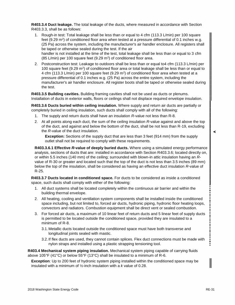
2018 Washington State Energy Code RE-31
<
R403.3.4 Duct leakage. The total leakage of the ducts, where measured in accordance with Section
R403.3.3, shall be as follows:
1. Rough-in test: Total leakage shall be less than or equal to 4 cfm (113.3 L/min) per 100 square
feet (9.29 m2) of conditioned floor area when tested at a pressure differential of 0.1 inches w.g.
(25 Pa) across the system, including the manufacturer's air handler enclosure. All registers shall
be taped or otherwise sealed during the test. If the air
handler is not installed at the time of the test, total leakage shall be less than or equal to 3 cfm
(85 L/min) per 100 square feet (9.29 m2) of conditioned floor area.
2. Postconstruction test: Leakage to outdoors shall be less than or equal to4 cfm (113.3 L/min) per
100 square feet (9.29 m2) of conditioned floor area or total leakage shall be less than or equal to
4 cfm (113.3 L/min) per 100 square feet (9.29 m2) of conditioned floor area when tested at a
pressure differential of 0.1 inches w.g. (25 Pa) across the entire system, including the
manufacturer's air handler enclosure. All register boots shall be taped or otherwise sealed during
the test.
R403.3.5 Building cavities. Building framing cavities shall not be used as ducts or plenums.
Installation of ducts in exterior walls, floors or ceilings shall not displace required envelope insulation.
R403.3.6 Ducts buried within ceiling insulation. Where supply and return air ducts are partially or
completely buried in ceiling insulation, such ducts shall comply with all of the following:
1. The supply and return ducts shall have an insulation R-value not less than R-8.
2. At all points along each duct, the sum of the ceiling insulation R-value against and above the top
of the duct, and against and below the bottom of the duct, shall be not less than R-19, excluding
the R-value of the duct insulation.
Exception: Sections of the supply duct that are less than 3 feet (914 mm) from the supply
outlet shall not be required to comply with these requirements.
R403.3.6.1 Effective R-value of deeply buried ducts. Where using a simulated energy performance
analysis, sections of ducts that are: installed in accordance with Section R403.3.6; located directly on,
or within 5.5 inches (140 mm) of the ceiling; surrounded with blown-in attic insulation having an R-
value of R-30 or greater and located such that the top of the duct is not less than 3.5 inches (89 mm)
below the top of the insulation, shall be considered as having an effective duct insulation R-value of
R-25.
R403.3.7 Ducts located in conditioned space. For ducts to be considered as inside a conditioned
space, such ducts shall comply with either of the following:
1. All duct systems shall be located completely within the continuous air barrier and within the
building thermal envelope.
2. All heating, cooling and ventilation system components shall be installed inside the conditioned
space including, but not limited to, forced air ducts, hydronic piping, hydronic floor heating loops,
convectors and radiators. Combustion equipment shall be direct vent or sealed combustion.
3. For forced air ducts, a maximum of 10 linear feet of return ducts and 5 linear feet of supply ducts
is permitted to be located outside the conditioned space, provided they are insulated to a
minimum of R-8.
3.1. Metallic ducts located outside the conditioned space must have both transverse and
longitudinal joints sealed with mastic.
3.2. If flex ducts are used, they cannot contain splices. Flex duct connections must be made with
nylon straps and installed using a plastic strapping tensioning tool.
R403.4 Mechanical system piping insulation. Mechanical system piping capable of carrying fluids
above 105°F (41°C) or below 55°F (13°C) shall be insulated to a minimum of R-6.
Exception: Up to 200 feet of hydronic system piping installed within the conditioned space may be
insulated with a minimum of ½-inch insulation with a k value of 0.28.

RE-32 2018 Washington State Energy Code
R403.4.1 Protection of piping insulation. Piping insulation exposed to weather shall be protected
from damage, including that caused by sunlight, moisture, equipment maintenance, and wind, and shall
provide shielding from solar radiation that can cause degradation of the material. Adhesive tape shall
not be permitted.
R403.5 Service hot water systems. Energy conservation measures for service hot water systems shall
be in accordance with Sections R403.5.1 through R403.5.5. Service water-heating equipment shall meet
the requirements of DOE 10 CFR Part 430 Uniform Energy Factor or the equipment shall meet the
requirements of Section C404.2.
R403.5.1 Heated water circulation and temperature maintenance system. Heated water circulation
systems shall be in accordance with Section R403.5.1.1. Heat trace temperature maintenance systems
shall be in accordance with Section R403.5.1.2. Automatic controls, temperature sensors and pumps
shall be accessible. Manual controls shall be readily accessible.
R403.5.1.1 Circulation systems. Heated water circulation systems shall be provided with a
circulation pump. The system return pipe shall be a dedicated return pipe or a cold water supply pipe.
Gravity and thermo-syphon circulation systems shall be prohibited. Controls for circulating hot water
system pumps shall start the pump based on the identification of a demand for hot water within the
occupancy. The controls shall automatically turn off the pump when the water in the circulation loop is
at the desired temperature and when there is no demand for hot water.
R403.5.1.2 Heat trace systems. Electric heat trace systems shall comply with IEEE 515.1 or UL 515.
Controls for such systems shall automatically adjust the energy input to the heat tracing to maintain
the desired water temperature in the piping in accordance with the times when heated water is used
in the occupancy.
R403.5.2 Demand recirculation water systems. Demand recirculation water systems shall have
controls that comply with both of the following:
1. The controls shall start the pump upon receiving a signal from the action of a user of a fixture or
appliance, sensing the presence of a user of a fixture or sensing the flow of hot or tempered
water to a fixture fitting or appliance.
2. The controls shall limit the temperature of the water entering the cold water piping to not greater
than 104ºF (40 ºC).
R403.5.3 Hot water pipe insulation. Insulation for hot water pipe, both within and outside the
conditioned space, shall have a minimum thermal resistance (R-value) of R-3.
Exception: Pipe insulation is permitted to be discontinuous where it passes through studs, joists or
other structural members and where the insulated pipes pass other piping, conduit or vents, provided
the insulation is installed tight to each obstruction.
R403.5.4 Drain water heat recovery units. Drain water heat recovery units shall comply with CSA
55.2 or IAPMO PS 92. Drain water heat recovery units shall be in accordance with CSA 55.1 or IAPMO
IGC 346-2017.
R403.5.5 Electric water heater insulation. All electric water heaters in unconditioned spaces, or on
concrete floors in conditioned spaces, shall be placed on an insulated surface with a minimum thermal
resistance of R-10, and a minimum compressive strength of 40 psi or engineered to support the
appliance.
R403.6 Mechanical ventilation. The building shall be provided with ventilation that meets the
requirements of the International Residential Code or International Mechanical Code, as applicable, or
with other approved means of ventilation. Outdoor air intakes and exhausts shall have automatic or
gravity dampers that close when the ventilation system is not operating.
R403.6.1 Whole-house mechanical ventilation system fan efficacy. Mechanical ventilation system
fans shall meet the efficacy requirements of Table R403.6.1.
Exception: Where an air handler that is integral to the tested and listed HVAC equipment is used to
provide whole-house ventilation, the air handler shall be powered by an electronically commutated
motor.

2018 Washington State Energy Code RE-33
<
TABLE R403.6.1 MECHANICAL VENTILATION SYSTEM FAN EFFICACY
FAN LOCATION AIR FLOW RATE MINIMUM (CFM)
MINIMUM EFFICACY (CFM/WATT)
AIR FLOW RATE MAXIMUM (CFM)
HRV or ERV Any 1.2 cfm/watt Any
Range hoods Any 2.8 cfm/watt Any
In-line fan Any 2.8 cfm/watt Any
Bathroom, utility room 10 1.4 cfm/watt < 90
Bathroom, utility room 90 2.8 cfm/watt Any
R403.7 Equipment sizing and efficiency rating. Heating and cooling equipment shall be sized in
accordance with ACCA Manual S based on building loads calculated in accordance with ACCA Manual J
or other approved heating and cooling calculation methodologies. The output capacity of heating and
cooling equipment shall not be greater than that of the smallest available equipment size that exceeds the
loads calculated, including allowable oversizing limits. Equipment shall meet the minimum federal
efficiency standards as referenced in Tables C403.3.2(1), C403.3.2(2), C403.3.2(3), C403.3.2(4),
C403.3.2(5), C403.3.2(6), C403.3.2(7), C403.3.2(8) and C403.3.2(9) and tested and rated in accordance
with the applicable test procedure.
R403.7.1 Electric resistance zone heated units. All detached one- and two-family dwellings and
multiple single-family dwellings (townhouses) up to three stories in height above grade plan using
electric zonal heating as the primary heat source shall install an inverter-driven ductless mini-split heat
pump in the largest zone in the dwelling. Building permit drawings shall specify the heating equipment
type and location of the heating system.
Exception: Total installed heating capacity of 2 kW per dwelling or less.
R403.8 Systems serving multiple dwelling units. Systems serving multiple dwelling units shall comply
with Sections C403 and C404 of the WSEC--Commercial Provisions in lieu of Section R403.
R403.9 Snow melt system controls. Snow and ice-melting systems, supplied through energy service to
the building, shall include automatic controls capable of shutting off the system when the pavement
temperature is above 50°F, and no precipitation is falling and an automatic or manual control that will
allow shutoff when the outdoor temperature is above 40°F.
R403.10 Pool and permanent spa energy consumption. Pools and permanent spas shall comply with
Sections R403.10.1 through R403.10.4.2.
R403.10.1 Heaters. The electric power to heaters shall be controlled by a readily accessible on-off
switch that is an integral part of the heater mounted on the exterior of the heater, or external to and
within 3 feet (914 mm) of the heater. Operation of such switch shall not change the settings of the
heater thermostat. Such switches shall be in addition to a circuit breaker for the power to the heater.
R403.10.2 Time switches. Time switches or other control method that can automatically turn off and
on according to a preset schedule shall be installed for heaters and pump motors. Heaters and pump
motors that have built in time switches shall be deemed in compliance with this requirement.
Exceptions:
1. Where public health standards require 24-hour pump operation.
2. Pumps that operate solar- and waste-heat-recovery pool heating systems.
R403.10.3 Covers. Outdoor heated pools and outdoor permanent spas shall be provided with a vapor-
retardant cover, or other approved vapor retardant means.
Exception: Where more than 75 percent of the energy for heating, computed over an operating
season of not less than three calendar months, is from a heat pump or on-site renewable energy
system, covers or other vapor-retardant means shall not be required.

RE-34 2018 Washington State Energy Code
R403.10.4 Residential pool pumps. Pool pump motors may not be split-phase or capacitor start-
induction run type.
R403.10.4.1 Two-speed capability.
1. Pump motors: Pool pump motors with a capacity of 1 hp or more shall have the capability of
operating at two or more speeds with low speed having a rotation rate that is no more than one-
half of the motor's maximum rotation rate.
2. Pump controls: Pool pump motor controls shall have the capability of operating the pool pump
with at least two speeds. The default circulation speed shall be the lowest speed, with a high
speed override capability being for a temporary period not to exceed one normal cycle.
R403.10.4.2 Pump operation. Circulating water systems shall be controlled so that the circulation
pump(s) can be conveniently turned off, automatically or manually, when the water system is not in
operation.
R403.11 Portable spas. The energy consumption of electric-powered portable spas shall be controlled
by the requirements of APSP-14.
R403.12 Residential pools and permanent residential spas. Residential swimming pools and
permanent residential spas that are accessory to detached one- and two-family dwellings and
townhouses three stories or less in height above grade plane and that are available only to the household
and its guests shall be in accordance with APSP-15.
SECTION R404 ELECTRICAL POWER AND LIGHTING SYSTEMS
R404.1 Lighting equipment. Not less than 90 percent of lamps in permanently installed lighting fixtures
shall be high-efficacy lamps.
R404.1.1 Lighting equipment. Fuel gas lighting systems shall not have continuously burning pilot
lights.
SECTION R405 SIMULATED PERFORMANCE ALTERNATIVE (PERFORMANCE)
R405.1 Scope. This section establishes criteria for compliance using simulated energy performance
analysis. Such analysis shall include heating, cooling, mechanical ventilation and service water heating
energy only.
R405.2 Mandatory requirements. Compliance with this section requires compliance with those sections
shown in Table R405.2. All supply and return ducts not completely inside the building thermal envelope
shall be insulated to a minimum of R-8.
R405.3 Performance-based compliance. Compliance based on simulated energy performance requires
that a proposed residence (proposed design) be shown to have an annual energy consumption based on
carbon emissions of the fuels and energy use in the proposed building. Carbon emissions for both the
standard reference design and the proposed design shall be calculated using Table R405.3. Energy use
derived from simulation analysis shall be expressed in pounds of carbon per square foot of conditioned
floor area as follows:
1. For structures less than 1,500 square feet of conditioned floor area, the annual carbon emissions
shall be less than or equal to 73 percent of the annual carbon emissions of the standard reference
design.
2. For structures 1,500 to 5,000 square feet of conditioned floor area, the annual carbon emissions
shall be no more than 56 percent of the standard reference design.
3. For structures over 5,000 square feet of conditioned floor area, the annual carbon emissions shall
be no more than 50 percent of the standard reference design.
4. For structures serving Group R-2 occupancies, the annual carbon emissions shall be less than or
equal to 70 percent of the annual carbon emissions of the standard reference design.

2018 Washington State Energy Code RE-35
TABLE R405.2 MANDATORY COMPLIANCE MEASURES FOR SIMULATED PERFORMANCE ALTERNATIVE
Section Title Comments
General
R401.3 Certificate
Envelope
R402.4 Air leakage
R402.5 Maximum fenestration U-factor
Systems
R403.1 Controls
R403.1.2 Heat pump supplemental heat
R403.3.2 Sealing
R403.3.1 Equipment and system sizing
R403.3.3 Duct testing
R403.3.4 Duct leakage
R403.3.5 Building cavities
R403.4 Mechanical system piping insulation
R403.5.1 Heated water circulation and temperature maintenance system
R403.6 Mechanical ventilation
R403.7 Equipment sizing and efficiency rating
R403.8 Systems serving multiple dwelling units
R403.9 Snow melt system controls
R403.10 Pool and permanent spa energy consumption
R403.11 Portable spas
Electrical Power and Lighting
R404.1 Lighting equipment
R404.1.1 Lighting equipment
Other Requirements
R406 Additional energy efficiency requirements
TABLE R405.3 CARBON EMISSIONS FACTORS
TYPE CO2e
(lb/unit) UNIT
Electricity 0.80 kWh
Natural gas 11.7 Therm
Oil 19.2 Gallon
Propane 10.5 Gallon
Othera 195.00 mmBtu
On-site renewable energy 0.00
a. District energy systems may use alternative emission factors supported by calculations approved by the code official.

RE-36 2018 Washington State Energy Code
R405.4 Documentation. Documentation of the software used for the performance design and the
parameters for the building shall be in accordance with Sections R405.4.1 through R405.4.3.
R405.4.1 Compliance software tools. Documentation verifying that the methods and accuracy of the
compliance software tools conform to the provisions of this section shall be provided to the code official.
R405.4.2 Compliance report. Compliance software tools shall generate a report that documents that
the proposed design complies with Section R405.3. A compliance report on the proposed design shall
be submitted with the application for the building permit. Upon completion of the building, a compliance
report based on the as-built condition of the building shall be submitted to the code official before a
certificate of occupancy is issued. Batch sampling of buildings to determine energy code compliance for
all buildings in the batch shall be prohibited.
Compliance reports shall include information in accordance with Sections R405.4.2.1 and R405.4.2.2.
Where the proposed design of a building could be built on different sites where the cardinal orientation
of the building on each site is different, compliance of the proposed design for the purposes of the
application for the building permit shall be based upon the worst-case orientation, worst-case
configuration, worst-case building air leakage and worst-case duct leakage. Such worst-case
parameters shall be used as inputs to the compliance software for energy analysis.
R405.4.2.1 Compliance report for permit application. A compliance report submitted with the
application for building permit shall include all of the following:
1. Building street address, or other building site identification.
2. A statement indicating that the proposed design complies with Section R405.3.
3. An inspection checklist documenting the building component characteristics of the proposed
design as indicated in Table R405.5.2(1). The inspection checklist shall show results for both
the standard reference design and the proposed design with all user inputs to the compliance
software to generate the results.
4. A site-specific energy analysis report that is in compliance with Section R405.3
5. Name of the individual performing the analysis and generating the report.
6. Name and version of the compliance software tool.
R405.4.2.2 Compliance report for certificate of occupancy. A compliance report submitted for
obtaining the certificate of occupancy shall include all of the following:
1. Building street address, or other building site identification
2. A statement indicating that the as-built building complies with Section R405.3.
3. A certificate indicating that the building passes the performance matrix for code compliance and
the energy saving features of the buildings.
4. A site-specific energy analysis report that is in compliance with Section R405.3.
5. Name of the individual performing the analysis and generating the report.
6. Name and version of the compliance software tool.
R405.4.3 Additional documentation. The code official shall be permitted to require the following
documents:
1. Documentation of the building component characteristics of the standard reference design.
2. A certification signed by the builder providing the building component characteristics of the
proposed design as given in Table R405.5.2(1).
3. Documentation of the actual values used in the software calculations for the proposed design.
R405.5 Calculation procedure. Calculations of the performance design shall be in accordance with
Sections R405.5.1 and R405.5.2.
R405.5.1 General. Except as specified by this section, the standard reference design and proposed
design shall be configured and analyzed using identical methods and techniques.
R405.5.2 Residence specifications. The standard reference design and proposed design shall be
configured and analyzed as specified by Table R405.5.2(1). Table R405.5.2(1) shall include by
reference all notes contained in Table R402.1.1.

2018 Washington State Energy Code RE-37
<
TABLE R405.5.2(1) SPECIFICATIONS FOR THE STANDARD REFERENCE AND PROPOSED DESIGNS
BUILDING COMPONENT
STANDARD REFERENCE DESIGN PROPOSED DESIGN
Above-grade walls
Type: Mass wall if proposed wall is mass; otherwise wood frame.
As proposed
Gross area: Same as proposed As proposed
U-factor: From Table R402.1.3 As proposed
Solar absorptance = 0.75 As proposed
Remittance = 0.90 As proposed
Below-grade walls
Type: Same as proposed As proposed
Gross area: Same as proposed As proposed
U-factor: From Table R402.1.3, with insulation layer on interior side of walls.
As proposed
Above-grade floors
Type: Wood frame As proposed
Gross area: Same as proposed As proposed
U-factor: From Table R402.1.3 As proposed
Ceilings
Type: Wood frame As proposed
Gross area: Same as proposed As proposed
U-factor: From Table R402.1.3 As proposed
Roofs
Type: Composition shingle on wood sheathing As proposed
Gross area: Same as proposed As proposed
Solar absorptance = 0.75 As proposed
Emittance = 0.90 As proposed
Attics Type: Vented with aperture = 1 ft2 per 300 ft2 ceiling area As proposed
Foundations
Type: Same as proposed foundation wall area above and below-grade
As proposed
Soil characteristics: Same as proposed. As proposed
Opaque Doors
Area: 40 ft2 As proposed
Orientation: North As proposed
U-factor: Same as fenestration from Table R402.1.3. As proposed
Vertical fenestration other than opaque doorsa
Total areah = (a) The proposed glazing area; where proposed glazing area is less than 15% of the conditioned floor area. (b) 15% of the conditioned floor area; where the proposed glazing area is 15% or more of the conditioned floor area.
As proposed
Orientation: Equally distributed to four cardinal compass orientations (N, E, S & W).
As proposed
U-factor: From Table R402.1.3 As proposed
SHGC: From Table R402.1.1 except that for climates with no requirement (NR) SHGC = 0.40 shall be used.
As proposed
Interior shade fraction: 0.92 - (0.21 × SHGC for the standard reference design) External shading: None
0.92 - (0.21 × SHGC as proposed) As proposed
Skylights None As proposed

RE-38 2018 Washington State Energy Code
TABLE R405.5.2(1) (continued) SPECIFICATIONS FOR THE STANDARD REFERENCE AND PROPOSED DESIGNS
BUILDING COMPONENT
STANDARD REFERENCE DESIGN PROPOSED DESIGN
Air exchange rate
Air leakage rate of 5 air changes per hour at a pressure of 0.2 inches w.g. (50 Pa).
As proposeda.
The mechanical ventilation rate shall be in addition to the air leakage rate and the same as in the proposed design, but no greater than 0.01 × CFA +7.5 × (Nbr + 1) where:
CFA = conditioned floor area Nbr = number of bedrooms
Energy recovery shall not be assumed for mechanical ventilation.
The mechanical ventilation rateb shall be in addition to the air leakage rate and shall be as proposed.
Mechanical ventilation
None, except where mechanical ventilation is specified by the proposed design, in which case:
Annual vent fan energy use: kWh/yr = (1ef) × (0.0876 x CFA + 65.7 × (Nbr + 1)
where: ef = the minimum exhaust fan efficacy from Table
R403.6.1 corresponding to a flow rate of 0.01 × CFA + 7.5 × (Nbr+1)
CFA = conditioned floor area Nbr = number of bedrooms
As proposed
Internal gains IGain = 17,900 + 23.8 × CFA + 4104 × Nbr (Btu/day per dwelling unit)
Same as standard reference design
Internal mass
An internal mass for furniture and contents of 8 pounds per square foot of floor area.
Same as standard reference design, plus any additional mass specifically designed as a thermal storage elementc but not integral to the building envelope or structure.
Structural mass
For masonry floor slabs, 80% of floor area covered by R-2 carpet and pad, and 20% of floor directly exposed to room air.
As proposed
For masonry basement walls, as proposed, but with insulation required by Table R402.1.3 located on the interior side of the walls.
As proposed
For other walls, for ceilings, floors, and interior walls, wood frame construction.
As proposed
Heating systemsd, e
Where the proposed design utilizes electric heating without a heat pump the standard reference design shall be an air source heat pump meeting the requirements of Section C403 of the WSEC—Commercial Provisions. For all other systems, the same system type as proposed, and the same system efficiency required by prevailing minimum federal standard.
Capacity: Sized in accordance with Section R403.6
As proposed
Cooling systemsd, f Same system type as proposed. Same system efficiency as required by prevailing minimum federal standard. Capacity: Sized in accordance with Section R403.6.
As proposed
Service water heatingd,e,f, g
Same system type as proposed. Same system efficiency as required by prevailing minimum federal standard. Use: Same as proposed design
As proposed gal/day = 30 + (10 × Nbr)

2018 Washington State Energy Code RE-39
TABLE R405.5.2(1) (continued) SPECIFICATIONS FOR THE STANDARD REFERENCE AND PROPOSED DESIGNS
BUILDING COMPONENT
STANDARD REFERENCE DESIGN PROPOSED DESIGN
Thermal distribution systems
Duct insulation: From Section R403.3.3 As specified in Table R405.5.2(2) A thermal distribution system efficiency (DSE) of 0.93
shall be applied to both the heating and cooling system efficiencies for all systems.
Exception: For non-ducted heating and cooling
systems that do not have a fan, the standard reference design distribution system efficiency (DSE) shall be 1.
Thermostat Type: Manual, cooling temperature setpoint = 75°F; Heating temperature setpoint = 72°F
Same as standard reference
For SI: 1 square foot = 0.93 m2, 1 British thermal unit = 1055 J, 1 pound per square foot = 4.88 kg/m2, 1 gallon (U.S.) = 3.785 L, °C = (°F-3)/1.8, 1 degree = 0.79 rad
a. Where required by the code official, testing shall be conducted by an approved party. Hourly calculations as specified in the ASHRAE Handbook of Fundamentals, or the equivalent, shall be used to determine the
energy loads resulting from infiltration.
b. The combined air exchange rate for infiltration and mechanical ventilation shall be determined in accordance with Equation 43 of 2001 ASHRAE Handbook of Fundamentals, page 26.24 and the "Whole-house Ventilation" provisions of 2001 ASHRAE Handbook of Fundamentals, page 26.19 for intermittent mechanical
ventilation.
c. Thermal storage element shall mean a component not part of the floors, walls or ceilings that is part of a passive solar system, and that provides thermal storage such as enclosed water columns, rock beds, or phase-change containers. A thermal storage element must be in the same room as fenestration that faces within 15 degrees (0.26 rad) of true south, or must be connected to such a room with pipes or ducts that allow the element to be actively charged.
d. For a proposed design with multiple heating, cooling or water heating systems using different fuel types, the applicable standard reference design system capacities and fuel types shall be weighted in accordance with their respective loads as calculated by accepted engineering practice for each equipment and fuel type present.
e. For a proposed design without a proposed heating system, a heating system with the prevailing federal minimum efficiency shall be assumed for both the standard reference design and proposed design.
f. For a proposed design home without a proposed cooling system, an electric air conditioner with the prevailing federal minimum efficiency shall be assumed for both the standard reference design and the proposed design.
g. For a proposed design with a nonstorage-type water heater, a 40-gallon storage-type water heater with the prevailing federal minimum energy factor for the same fuel as the predominant heating fuel type shall be assumed. For the case of a proposed design without a proposed water heater, a 40-gallon storage-type water heater with the prevailing federal minimum efficiency for the same fuel as the predominant heating fuel type shall be assumed for both the proposed design and standard reference design.
h For residences with conditioned basements, R-2 and R-4 residences and townhouses, the following formula shall be used to determine fenestration area:
AF = As x FA x F Where:
AF = Total fenestration area. As = Standard reference design total fenestration area.
FA = (Above-grade thermal boundary gross wall area)/(above-grade boundary wall area + 0.5 x below-grade boundary wall area).
F = (Above-grade thermal boundary wall area)/(above-grade thermal boundary wall area + common wall area) or 0.56, whichever is greater.
and where: Thermal boundary wall is any wall that separates conditioned space from unconditioned space or
ambient conditions. Above-grade thermal boundary wall is any thermal boundary wall component not in contact with soil. Below-grade boundary wall is any thermal boundary wall in soil contact. Common wall area is the area of walls shared with an adjoining dwelling unit. L and CFA are in the same units.

RE-40 2018 Washington State Energy Code
TABLE R405.5.2(2) DEFAULT DISTRIBUTION SYSTEM EFFICIENCIES FOR PROPOSED DESIGNSa
DISTRIBUTION SYSTEM CONFIGURATION AND
CONDITION
DISTRIBUTION SYSTEM
EFFICIENCY
Distribution system components located in unconditioned space
0.88
Distribution systems entirely located in conditioned spaceb
0.93
Zonal systemsc 1.00
For SI: 1 cubic foot per minute = 0.47 L/s, 1 square foot = 0.093m2, 1 pound per square inch = 6895 Pa, 1 inch water gauge = 1250 Pa.
a. Values given by this table are for distribution systems, which must still meet all prescriptive requirements for duct and pipe system insulation and leakage.
b. Entire system in conditioned space shall mean that no component of the distribution system, including the air-handler unit, is located outside of the conditioned space. All components must be located on the interior side of the thermal envelope (inside the insulation) and also inside of the air barrier. Refrigerant compressors and piping are allowed to be located outside.
c. Zonal systems are systems where the heat source is located within each room. Systems shall be allowed to have forced airflow across a coil but shall not have any ducted airflow external to the manufacturer’s air-handler enclosure. Hydronic systems do not qualify.
R405.6 Calculation software tools. Calculation software, where used, shall be in accordance with Sections R405.6.1 through R405.6.3.
R405.6.1 Minimum capabilities. Calculation procedures used to comply with this section shall be software tools capable of calculating the annual energy consumption of all building elements that differ between the standard reference design and the proposed design and shall include the following capabilities:
1. Calculation of whole-building (as a single zone) sizing for the heating and cooling equipment in the standard reference design residence in accordance with Section R403.6.
2. Calculations that account for the effects of indoor and outdoor temperatures and part-load ratios on the performance of heating, ventilating and air-conditioning equipment based on climate and equipment sizing.
3. Printed code official inspection checklist listing each of the proposed design component characteristics from Table R405.5.2(1) determined by the analysis to provide compliance, along with their respective performance ratings (e.g., R-value, U-factor, SHGC, HSPF, AFUE, SEER, EF, etc.).
R405.6.2 Specific approval. Performance analysis tools meeting the applicable sections of Section R405 shall be permitted to be approved. Tools are permitted to be approved based on meeting a specified threshold for a jurisdiction. The code official shall be permitted to approve tools for a specified application or limited scope.
R405.6.3 Input values. When calculations require input values not specified by Sections R402, R403, R404 and R405, those input values shall be taken from an approved source.

2018 Washington State Energy Code RE-41
SECTION R406 ADDITIONAL ENERGY EFFICIENCY REQUIREMENTS
R406.1 Scope. This section establishes additional energy efficiency requirements for all new construction covered by this code, including additions subject to Section R502 and change of occupancy or use subject to Section R505 unless specifically exempted in Section R406. Credit from both Sections R406.2 and R406.3 are required.
R406.2 Carbon emission equalization. This section establishes a base equalization between fuels used
to define the equivalent carbon emissions of the options specified. The permit shall define the base fuel
selection to be used and the points specified in Table R406.2 shall be used to modify the requirements in
Section R406.3. The sum of credits from Tables R406.2 and R406.3 shall meet the requirements of
Section R406.3.
R406.3 Additional energy efficiency requirements. Each dwelling unit in a residential building shall comply with sufficient options from Table R406.2 so as to achieve the following minimum number of credits:
1. Small Dwelling Unit: ........................................................................................... 3.0 credits Dwelling units less than 1500 square feet in conditioned floor area with less than 300 square feet of fenestration area. Additions to existing building greater than 500 square feet of heated floor area but less than 1500 square feet.
2. Medium Dwelling Unit: ...................................................................................... 6.0 credits All dwelling units that are not included in #1, #3 or #4.
3. Large Dwelling Unit: .......................................................................................... 7.0 credits Dwelling units exceeding 5000 square feet of conditioned floor area.
4. Dwelling units serving R-2 occupancies: ........................................................... 4.5 credits
5. Additions less than or equal to 500 square feet:................................................ 1.5 credits
The drawings included with the building permit application shall identify which options have been selected and the point value of each option, regardless of whether separate mechanical, plumbing, electrical, or other permits are utilized for the project.
TABLE R406.2
FUEL NORMALIZATION CREDITS
System Type
Description of Primary Heating Source Credits
All Other Group R-2
1 Combustion heating equipment meeting minimum federal efficiency standards for the equipment listed in Table C403.3.2(4) or C403.3.2(5)
0 0
2 For an initial heating system using a heat pump that meets federal standards for the equipment listed in Table C403.3.2(1)C or C403.3.2(2)
or
Air to water heat pump units that are configured to provide both heating and cooling and are rated in accordance with AHRI 550/590
1.0 1.0
3 For heating system based on electric resistance only (either forced air or Zonal)
-1.0 -1.0
4 For heating system based on electric resistance with a ductless mini-split heat pump system in accordance with Section R403.7.1 including the exception
0.5 N/A
5 All other heating systems -1 -0.5

RE-42 2018 Washington State Energy Code
TABLE 406.3 ENERGY CREDITS
OPTION DESCRIPTION CREDIT(S)
All Other Group R-2
1. EFFICIENT BUILDING ENVELOPE OPTIONS
Only one option from Items 1.1 through 1.7 may be selected in this category.
Compliance with the conductive UA targets is demonstrated using Section R402.1.4, Total UA alternative, where [1-(Proposed UA/Target UA)] > the required %UA reduction
1.1 Prescriptive compliance is based on Table R402.1.1 with the following modifications:
Vertical fenestration U = 0.24.
0.5 0.5
1.2 Prescriptive compliance is based on Table R402.1.1 with the following modifications:
Vertical fenestration U = 0.20.
1.0 1.0
1.3 Prescriptive compliance is based on Table R402.1.1 with the following modifications:
Vertical fenestration U = 0.28
Floor R-38
Slab on grade R-10 perimeter and under entire slab
Below grade slab R-10 perimeter and under entire slab
or
Compliance based on Section R402.1.4: Reduce the Total conductive UA by 5%.
0.5 N/A
1.4 Prescriptive compliance is based on Table R402.1.1 with the following modifications:
Vertical fenestration U = 0.25
Wall R-21 plus R-4 ci
Floor R-38
Basement wall R-21 int plus R-5 ci
Slab on grade R-10 perimeter and under entire slab
Below grade slab R-10 perimeter and under entire slab
or
Compliance based on Section R402.1.4: Reduce the Total conductive UA by 15%.
1.0 1.0
1.5 Prescriptive compliance is based on Table R402.1.1 with the following modifications:
Vertical fenestration U = 0.22
Ceiling and single-rafter or joist-vaulted R-49 advanced
Wood frame wall R-21 int plus R-12 ci
Floor R-38
Basement wall R-21 int plus R-12 ci
Slab on grade R-10 perimeter and under entire slab
Below grade slab R-10 perimeter and under entire slab
or
Compliance based on Section R402.1.4: Reduce the Total conductive UA by 30%.
2.0 1.5

2018 Washington State Energy Code RE-43
TABLE 406.3 (continued) ENERGY CREDITS
OPTION DESCRIPTION CREDIT(S)
All Other Group R-2
1.6 Prescriptive compliance is based on Table R402.1.1 with the following modifications:
Vertical fenestration U = 0.18
Ceiling and single-rafter or joist-vaulted R-60 advanced
Wood frame wall R-21 int plus R-16 ci
Floor R-48
Basement wall R-21 int plus R-16 ci
Slab on grade R-20 perimeter and under entire slab
Below grade slab R-20 perimeter and under entire slab
or
Compliance based on Section R402.1.4: Reduce the Total conductive UA by 40%.
3.0 2.0
1.7 Advanced framing and raised heel trusses or rafters
Vertical Glazing U-0.28
R-49 Advanced (U-0.020) as listed in Section A102.2.1, Ceilings below a vented attic
and
R-49 vaulted ceilings with full height of uncompressed insulation extending over the wall top plate at the eaves.
0.5 0.5
2. AIR LEAKAGE CONTROL AND EFFICIENT VENTILATION OPTIONS
Only one option from Items 2.1 through 2.4 may be selected in this category.
2.1 Compliance based on R402.4.1.2:
Reduce the tested air leakage to 3.0 air changes per hour maximum at 50 Pascals
or
For R-2 Occupancies, optional compliance based on Section R402.4.1.2: Reduce the tested air leakage to 0.3 cfm/ft2 maximum at 50 Pascals
and
All whole house ventilation requirements as determined by Section M1507.3 of the International Residential Code or Section 403.8 of the International Mechanical Code shall be met with a high efficiency fan(s) (maximum 0.35 watts/cfm), not interlocked with the furnace fan (if present). Ventilation systems using a furnace including an ECM motor are allowed, provided that they are controlled to operate at low speed in ventilation only mode.
To qualify to claim this credit, the building permit drawings shall specify the option being selected, the maximum tested building air leakage, and shall show the qualifying ventilation system and its control sequence of operation.
0.5 1.0

RE-44 2018 Washington State Energy Code
TABLE 406.3 (continued) ENERGY CREDITS
OPTION DESCRIPTION CREDIT(S)
All Other Group R-2
2.2 Compliance based on Section R402.4.1.2:
Reduce the tested air leakage to 2.0 air changes per hour maximum at 50 Pascals
or
For R-2 Occupancies, optional compliance based on Section R402.4.1.2: Reduce the tested air leakage to 0.25 cfm/ft2 maximum at 50 Pascals
and
All whole house ventilation requirements as determined by Section M1507.3 of the International Residential Code or Section 403.8 of the International Mechanical Code shall be met with a heat recovery ventilation
system with minimum sensible heat recovery efficiency of 0.65.
To qualify to claim this credit, the building permit drawings shall specify the option being selected and shall specify the maximum tested building air leakage and shall show the heat recovery ventilation system.
1.0 1.5
2.3 Compliance based on Section R402.4.1.2:
Reduce the tested air leakage to 1.5 air changes per hour maximum at 50 Pascals
or
For R-2 Occupancies, optional compliance based on Section R402.4.1.2: Reduce the tested air leakage to 0.25 cfm/ft2 maximum at 50 Pascals
and
All whole house ventilation requirements as determined by Section M1507.3 of the International Residential Code or Section 403.8 of the International Mechanical Code shall be met with a heat recovery ventilation system with minimum sensible heat recovery efficiency of 0.75.
To qualify to claim this credit, the building permit drawings shall specify the option being selected and shall specify the maximum tested building air leakage and shall show the heat recovery ventilation system.
1.5 2.0
2.4 Compliance based on Section R402.4.1.2:
Reduce the tested air leakage to 0.6 air changes per hour maximum at 50 Pascals
or
For R-2 Occupancies, optional compliance based on Section R402.4.1.2: Reduce the tested air leakage to 0.15 cfm/ft2 maximum at 50 Pascals
and
All whole house ventilation requirements as determined by Section M1507.3 of the International Residential Code or Section 403.8 of the International Mechanical Code shall be met with a heat recovery ventilation system with minimum sensible heat recovery efficiency of 0.80. Duct installation shall comply with Section R403.3.7.
To qualify to claim this credit, the building permit drawings shall specify the option being selected and shall specify the maximum tested building air leakage and shall show the heat recovery ventilation system.
2.0 2.5

2018 Washington State Energy Code RE-45
TABLE 406.3 (continued) ENERGY CREDITS
OPTION DESCRIPTION CREDIT(S)
All Other Group R-2
3. HIGH EFFICIENCY HVAC EQUIPMENT OPTIONS
Only one option from Items 3.1 through 3.6 may be selected in this category.
3.1a Energy Star rated (U.S. North) Gas or propane furnace with minimum AFUE of 95%
or
Energy Star rated (U.S. North) Gas or propane boiler with minimum AFUE of 90%.
To qualify to claim this credit, the building permit drawings shall specify the option being selected and shall specify the heating equipment type and the minimum equipment efficiency.
1.0 1.0
3.2a Air-source centrally ducted heat pump with minimum HSPF of 9.5.
To qualify to claim this credit, the building permit drawings shall specify the option being selected and shall specify the heating equipment type and the minimum equipment efficiency.
1.0 N/A
3.3a Closed-loop ground source heat pump; with a minimum COP of 3.3
or
Open loop water source heat pump with a maximum pumping hydraulic head of 150 feet and minimum COP of 3.6.
To qualify to claim this credit, the building permit drawings shall specify the option being selected and shall specify the heating equipment type and the minimum equipment efficiency.
1.5 1.0
3.4 Ductless mini-split heat pump system, zonal control: In homes where the primary space heating system is zonal electric heating, a ductless mini-split heat pump system with a minimum HSPF of 10.0 shall be installed and provide heating to the largest zone of the housing unit.
To qualify to claim this credit, the building permit drawings shall specify the option being selected and shall specify the heating equipment type and the minimum equipment efficiency.
1.5 2.0
3.5a Air-source, centrally ducted heat pump with minimum HSPF of 11.0.
To qualify to claim this credit, the building permit drawings shall specify the option being selected and shall specify the heating equipment type and the minimum equipment efficiency.
1.5 N/A
3.6a Ductless split system heat pumps with no electric resistance heating in the primary living areas. A ductless heat pump system with a minimum HSPF of 10 shall be sized and installed to provide heat to entire dwelling unit at the design outdoor air temperature.
To qualify to claim this credit, the building permit drawings shall specify the option being selected, the heated floor area calculation, the heating equipment type(s), the minimum equipment efficiency, and total installed heat capacity (by equipment type).
2.0 3.0

RE-46 2018 Washington State Energy Code
TABLE 406.3 (continued) ENERGY CREDITS
OPTION DESCRIPTION CREDIT(S)
All Other Group R-2
4. HIGH EFFICIENCY HVAC DISTRIBUTION SYSTEM OPTIONS
4.1 All supply and return ducts located in an unconditioned attic shall be deeply buried in ceiling insulation in accordance with Section R403.3.7.
For mechanical equipment located outside the conditioned space, a maximum of 10 linear feet of return duct and 5 linear feet of supply duct connections to the equipment may be outside the deeply buried insulation. All metallic ducts located outside the conditioned space must have both transverse and longitudinal joints sealed with mastic. If flex ducts are used, they cannot contain splices.
Duct leakage shall be limited to 3 cfm per 100 square feet of conditioned floor area.
Air handler(s) shall be located within the conditioned space.
0.5 0.5
4.2 HVAC equipment and associated duct system(s) installation shall comply with the requirements of Section R403.3.7.
Locating system components in conditioned crawl spaces is not permitted under this option.
Electric resistance heat and ductless heat pumps are not permitted under this option.
Direct combustion heating equipment with AFUE less than 80% is not permitted under this option.
To qualify to claim this credit, the building permit drawings shall specify the option being selected and shall specify the heating equipment type and shall show the location of the heating and cooling equipment and all the ductwork.
1.0 N/A
5. EFFICIENT WATER HEATING OPTIONS
Only one option from Items 5.2 through 5.6 may be selected in this category. Item 5.1 may be combined with any option.
5.1 A drain water heat recovery unit(s) shall be installed, which captures waste water heat from all and only the showers, and has a minimum efficiency of 40% if installed for equal flow or a minimum efficiency of 54% if installed for unequal flow. Such units shall be rated in accordance with CSA B55.1 or IAPMO IGC 346-2017 and be so labeled.
To qualify to claim this credit, the building permit drawings shall include a plumbing diagram that specifies the drain water heat recovery units and the plumbing layout needed to install it. Labels or other documentation shall be provided that demonstrates that the unit complies with the standard.
0.5 0.5
5.2 Water heating system shall include one of the following:
Energy Star rated gas or propane water heater with a minimum UEF of 0.80.
To qualify to claim this credit, the building permit drawings shall specify the option being selected and shall specify the water heater equipment type and the minimum equipment efficiency.
0.5 0.5

2018 Washington State Energy Code RE-47
TABLE 406.3 (continued) ENERGY CREDITS
OPTION DESCRIPTION CREDIT(S)
All Other Group R-2
5.3 Water heating system shall include one of the following:
Energy Star rated gas or propane water heater with a minimum UEF of 0.91
or
Solar water heating supplementing a minimum standard water heater. Solar water heating will provide a rated minimum savings of 85 therms or 2000 kWh based on the Solar Rating and Certification Corporation (SRCC) Annual Performance of OG-300 Certified Solar Water Heating Systems
or
Water heater heated by ground source heat pump meeting the requirements of Option 3.3.
To qualify to claim this credit, the building permit drawings shall specify the option being selected and shall specify the water heater equipment type and the minimum equipment efficiency and, for solar water heating systems, the calculation of the minimum energy savings.
1.0 1.0
5.4 Water heating system shall include one of the following:
Electric heat pump water heater meeting the standards for Tier I of NEEA's advanced water heating specification
or
For R-2 Occupancy, electric heat pump water heater(s), meeting the standards for Tier I of NEEA's advanced water heating specification, shall supply domestic hot water to all units. If one water heater is serving more than one dwelling unit, all hot water supply and recirculation piping shall be insulated with R-8 minimum pipe insulation.
To qualify to claim this credit, the building permit drawings shall specify the option being selected and shall specify the water heater equipment type and the minimum equipment efficiency.
1.5 2.0
5.5 Water heating system shall include one of the following:
Electric heat pump water heater meeting the standards for Tier III of NEEA's advanced water heating specification
or
For R-2 Occupancy, electric heat pump water heater(s), meeting the standards for Tier III of NEEA's advanced water heating specification, shall supply domestic hot water to all units. If one water heater is serving more than one dwelling unit, all hot water supply and recirculation piping shall be insulated with R-8 minimum pipe insulation.
To qualify to claim this credit, the building permit drawings shall specify the option being selected and shall specify the water heater equipment type and the minimum equipment efficiency.
2.0 2.5

RE-48 2018 Washington State Energy Code
TABLE 406.3 (continued) ENERGY CREDITS
OPTION DESCRIPTION CREDIT(S)
All Other Group R-2
5.6 Water heating system shall include one of the following:
Electric heat pump water heater with a minimum UEF of 2.9 and utilizing a split system configuration with the air-to-refrigerant heat exchanger located outdoors. Equipment shall meet Section 4, requirements for all units, of the NEEA standard Advanced Water Heating Specification with the UEF noted above
or
For R-2 Occupancy, electric heat pump water heater(s), meeting the standards for Tier III of NEEA's advanced water heating specification and utilizing a split system configuration with the air-to-refrigerant heat exchanger located outdoors, shall supply domestic hot water to all units. If one water heater is serving more than one dwelling unit, all hot water supply and recirculation piping shall be insulated with R-8 minimum pipe insulation.
To qualify to claim this credit, the building permit drawings shall specify the option being selected and shall specify the water heater equipment type and the minimum equipment efficiency.
2.5 3.0
6. RENEWABLE ELECTRIC ENERGY OPTION
6.1 For each 1200 kWh of electrical generation per housing unit provided annually by on-site wind or solar equipment a 1.0 credit shall be allowed, up to 3 credits. Generation shall be calculated as follows:
For solar electric systems, the design shall be demonstrated to meet this requirement using the National Renewable Energy Laboratory calculator PVWATTs or approved alternate by the code official.
Documentation noting solar access shall be included on the plans.
For wind generation projects designs shall document annual power generation based on the following factors:
The wind turbine power curve; average annual wind speed at the site; frequency distribution of the wind speed at the site and height of the tower.
To qualify to claim this credit, the building permit drawings shall specify the option being selected and shall show the photovoltaic or wind turbine equipment type, provide documentation of solar and wind access, and include a calculation of the minimum annual energy power production.
1.0 1.0
7. APPLIANCE PACKAGE OPTION
7.1 All of the following appliances shall be new and installed in the dwelling unit and shall meet the following standards:
Dishwasher – Energy Star rated
Refrigerator (if provided) – Energy Star rated
Washing machine – Energy Star rated
Dryer – Energy Star rated, ventless dryer with a minimum CEF rating of 5.2.
To qualify to claim this credit, the building permit drawings shall specify the option being selected and shall show the appliance type and provide documentation of Energy Star compliance. At the time of inspection, all appliances shall be installed and connected to utilities. Dryer ducts and exterior dryer vent caps are not permitted to be installed in the dwelling unit.
0.5 1.5
a. An alternative heating source sized at a maximum of 0.5 Watts/ft2 (equivalent) of heated floor area or 500 Watts, whichever is bigger, may be installed in the dwelling unit.

2018 Washington State Energy Code RE-49
SECTION R407 CERTIFIED PASSIVE HOUSE
R407.1 General. Projects shall comply with Section R407.2 or R407.3.
R407.2 Passive House Institute U.S. (PHIUS). Projects shall comply with PHIUS+ 2018 Passive
Building Standard, including its USDOE Energy Star and Zero Energy Ready Home co-requisites, and
performance calculations by PHIUS-approved software. Projects shall also comply with the provisions of
Table R405.2.
R407.2.1 PHIUS documentation. Prior to the issuance of a building permit, the following items must be
provided to the code official:
1. A list of compliance features.
2. A PHIUS precertification letter.
Prior to the issuance of a certificate of occupancy, the following item must be provided to the code
official:
1. A PHIUS+ 2018 (or later) project certificate.
R407.3 Passive House Institute (PHI). Projects shall comply with Low Energy Building Standard,
version 9f or later, including performance calculations by PHI-approved software. Projects shall also
comply with the provisions of Section R401 through R404.
R407.3.1 PHI documentation. Prior to the issuance of a building permit, the following items must be
provided to the code official:
1. A list of compliance features.
2. A statement from a passive house certifier that the modeled energy performance is congruent
with the plans and specifications, and that the modeled performance meets said standard.
Prior to the issuance of a certificate of occupancy, the following item must be provided to the code
official:
1. A PHI Low Energy Building project certificate.
RE-50 2018 Washington State Energy Code

2018 Washington State Energy Code RE-51
CHAPTER 5
EXISTING BUILDINGS
SECTION R501
GENERAL
R501.1 Scope. The provisions of this chapter shall control the alteration, repair, addition and change of occupancy of existing buildings and structures.
R501.1.1 Additions, alterations, or repairs. Additions, alterations, or repairs to an existing building, building system or portion thereof shall comply with Sections R502, R503 or R504. Unaltered portions of the existing building or building supply system shall not be required to comply with this code.
R501.1.2 Thermostats for accessory dwelling units. Where a separate dwelling unit, that provides independent facilities for living, sleeping, cooking, bathing and sanitation, is established within or attached to an existing dwelling unit, the heating and cooling for the newly-created dwelling unit shall be controllable with a separate programmable thermostat in accordance with Section R403.1.1.
R501.2 Existing buildings. Except as specified in this chapter, this code shall not be used to require the removal, alteration or abandonment of, nor prevent the continued use and maintenance of, an existing building or building system lawfully in existence at the time of adoption of this code.
R501.3 Maintenance. Buildings and structures, and parts thereof, shall be maintained in a safe and sanitary condition. Devices and systems that are required by this code shall be maintained in conformance with the code edition under which installed. The owner or the owner’s authorized agent shall be responsible for the maintenance of buildings and structures. The requirements of this chapter shall not provide the basis for removal or abrogation of energy conservation, fire protection and safety systems and devices in existing structures.
R501.4 Compliance. Alterations, repairs, additions and changes of occupancy to, or relocation of, existing buildings and structures shall comply with the provisions for alterations, repairs, additions and changes of occupancy or relocation, respectively, in this code and the International Residential Code, International Building Code, International Existing Building Code, International Fire Code, International Fuel Gas Code, International Mechanical Code, Uniform Plumbing Code, International Property Maintenance Code, and NFPA 70.
R501.5 New and replacement materials. Except as otherwise required or permitted by this code, materials permitted by the applicable code for new construction shall be used. Like materials shall be permitted for repairs, provided hazards to life, health or property are not created. Hazardous materials shall not be used where the code for new construction would not permit their use in buildings of similar occupancy, purpose and location.
R501.6 Historic buildings. The building official may modify the specific requirements of this code for historic buildings and require alternate provisions which will result in a reasonable degree of energy efficiency. This modification may be allowed for those buildings or structures that are listed in the state or national register of historic places; designated as a historic property under local or state designation law or survey; certified as a contributing resource with a national register listed or locally designated historic district; or with an opinion or certification that the property is eligible to be listed on the national or state registers of historic places either individually or as a contributing building to a historic district by the state historic preservation officer or the keeper of the national register of historic places.

RE-52 2018 Washington State Energy Code
SECTION R502 ADDITIONS
R502.1 General. Additions to an existing building, building system or portion thereof shall conform to the provisions of this code as those provisions relate to new construction without requiring the unaltered portion of the existing building or building system to comply with this code. Additions shall not create an unsafe or hazardous condition or overload existing building systems. An addition shall be deemed to comply with this code where the addition alone complies, where the existing building and addition comply with this code as a single building, or where the building with the addition uses no more energy than the existing building. Additions shall be in accordance with Section R502.1.1 or R502.1.2.
R502.1.1 Prescriptive compliance. Additions shall comply with Sections R502.1.1.1 through R502.1.1.4.
R502.1.1.1 Building envelope. New building envelope assemblies that are part of the addition shall comply with Sections R402.1, R402.2, R402.3.1 through R402.3.5, and R402.4.
Exception: Where nonconditioned space is changed to conditioned space, the building envelope of the addition shall comply where the UA, as determined in Section R402.1.4, of the existing building and the addition, and any alterations that are part of the project, is less than or equal to the UA generated for the existing building.
R502.1.1.2 Heating and cooling systems. New heating, cooling and duct systems that are part of the addition shall comply with Section R403.
Exception: The following need not comply with the testing requirements of Section R403.3.3:
1. Additions of less than 750 square feet.
2. Duct systems that are documented to have been previously sealed as confirmed through field verification and diagnostic testing in accordance with procedures in WSU RS-33.
3. Ducts with less than 40 linear feet in unconditioned spaces.
4. Existing duct systems constructed, insulated or sealed with asbestos.
R502.1.1.3 Service hot water systems. New service hot water systems that are part of the addition shall comply with Section R403.5.
R502.1.1.4 Lighting. New lighting systems that are part of the addition shall comply with Section 404.1.
R502.1.2 Existing plus addition compliance (Simulated Performance Alternative). Where nonconditioned space is changed to conditioned space the addition shall comply where the annual energy use of the addition and the existing building, and any alterations that are part of the project, is less than or equal to the annual energy use of the existing building when modeled in accordance with Section R405. The addition and any alterations that are part of the project shall comply with Section R405 in its entirety.
SECTION R503 ALTERATIONS
R503.1 General. Alterations to any building or structure shall comply with the requirements of the code for new construction. Alterations shall be such that the existing building or structure is no less conforming to the provisions of this code than the existing building or structure was prior to the alteration.
Alterations to an existing building, building system or portion thereof shall conform to the provisions of this code as they relate to new construction without requiring the unaltered portions of the existing building or building system to comply with this code. Alterations shall not create an unsafe or hazardous condition or overload existing building systems.
Alterations shall be such that the existing building or structure uses no more energy than the existing building or structure prior to the alteration. Alterations to existing buildings shall comply with Section R503.1.1 through R503.2.

2018 Washington State Energy Code RE-53
The code official may approve designs of alterations which do not fully conform to all of the requirements of this code where in the opinion of the building official full compliance is physically impossible and/or economically impractical and:
1. The alteration improves the energy efficiency of the building; or 2. The alteration is energy efficient and is necessary for the health, safety, and welfare of the
general public.
R503.1.1 Building envelope. Building envelope assemblies that are part of the alteration shall comply with Section R402.1.1 or R402.1.4, Sections R402.2.1 through R402.2.11, R402.3.1, R402.3.2, R402.4.3 and R402.4.4.
Exception: The following alterations need not comply with the requirements for new construction provided the energy use of the building is not increased:
1. Storm windows installed over existing fenestration.
2. Existing ceiling, wall or floor cavities exposed during construction provided that these cavities are filled with insulation. 2x4 framed walls shall be insulated to a minimum of R-15 and 2x6 framed walls shall be insulated to a minimum of R-21.
3. Construction where the existing roof, wall or floor cavity is not exposed.
4. Roof recover.
5. Roofs without insulation in the cavity and where the sheathing or insulation is exposed during reroofing shall be insulated either above or below the sheathing.
6. Surface-applied window film installed on existing single pane fenestration assemblies to reduce solar heat gain provided the code does not require the glazing fenestration to be replaced.
R503.1.1.1 Replacement fenestration. Where some or all of an existing fenestration unit is replaced with a new fenestration product, including sash and glazing, the replacement fenestration unit shall meet the applicable requirements for U-factor and SHGC in Table R402.1.1. Where more than one replacement fenestration unit is being installed, an area-weighted average of the U-factor and SHGC of all replacement fenestration shall be permitted to be used to demonstrate compliance.
R503.1.2 Heating and cooling systems. New heating, cooling and duct systems that are part of the alteration shall comply with Section R403.
Exceptions:
1. Where ducts from an existing heating and cooling system are extended, duct systems with less than 40 linear feet in unconditioned spaces shall not be required to be tested in accordance with Section R403.2.2.
2. Existing duct systems constructed, insulated or sealed with asbestos.
R503.1.3 Service hot water systems. New service hot water systems that are part of the alteration shall comply with Section R403.5.
R503.1.4 Lighting. New lighting systems that are part of the alteration shall comply with Section R404.1.
Exception: Alterations that replace less than 50 percent of the luminaires in a space, provided that such alterations do not increase the installed interior lighting power.
R503.2 Change in space conditioning. Any nonconditioned or low-energy space that is altered to become conditioned space shall be required to be brought into full compliance with this code.
Exception: Where the simulated performance option in Section R405 is used to comply with this section, the annual energy use of the proposed design is permitted to be 110 percent of the annual energy use otherwise allowed by Section R405.3.

RE-54 2018 Washington State Energy Code
SECTION R504 REPAIRS
R504.1 General. Buildings, structures and parts thereof shall be repaired in compliance with Section R501.3 and this section. Work on nondamaged components that is necessary for the required repair of damaged components shall be considered part of the repair and shall not be subject to the requirements for alterations in this chapter. Routine maintenance required by Section R501.3, ordinary repairs exempt from permit, and abatement of wear due to normal service conditions shall not be subject to the requirements for repairs in this section.
The code official may approve designs of repairs which do not fully conform with all of the requirements of this code where in the opinion of the building official full compliance is physically impossible and/or economically impractical and:
1. The repair improves the energy efficiency of the building; or2. The repair is energy efficient and is necessary for the health, safety, and welfare of the general
public.
R504.2 Application. For the purposes of this code, the following shall be considered repairs.
1. Glass only replacements in an existing sash and frame.
2. Roof repairs.
3. Repairs where only the bulb and/or ballast within the existing luminaires in a space are replacedprovided that the replacement does not increase the installed interior lighting power.
SECTION R505 CHANGE OF OCCUPANCY OR USE
R505.1 Change in occupancy or use. Any space not within the scope of Section R101.2 which is converted to space that is within the scope of Section R101.2 shall be brought into full compliance with this code.
Spaces undergoing a change in occupancy that would result in an increase in demand for either fossil fuel or electrical energy shall comply with this code.
Any space that is converted to a dwelling unit or portion thereof from another use or occupancy shall comply with this code.
Exception: Where the simulated performance option in Section R405 is used to comply with this section, the annual energy use of the proposed design is permitted to be 110 percent of the annual energy use otherwise allowed by Section R405.3.

2018 Washington State Energy Code RE-55
CHAPTER 6
REFERENCED STANDARDS
This chapter lists the standards that are referenced in various sections of this document. The standards are listed herein by the promulgating agency of the standard, the standard identification, the effective date and title, and the section or sections of this document that reference the standard. The application of the referenced standards shall be as specified in Section R106.
AAMA American Architectural Manufacturers Association 1827 Walden Office Square Suite 550 Schaumburg, IL 60173-4268
Standard Referenced reference in code number Title section number
AAMA/WDMA/CSA 101/I.S.2/A C440—17 North American Fenestration Standard/ Specifications for Windows, Doors and Unit Skylights ...................................... R402.4.3
ACCA Air Conditioning Contractors of America 2800 Shirlington Road, Suite 300 Arlington, VA 22206
Standard Referenced reference in code number Title section number
Manual J—16 Residential Load Calculation Eighth Edition ........................................................... R403.6 Manual S—14 Residential Equipment ............................................................................................ R403.6
ANSI America National Standards Institute 25 West 43rd Street, 4th Floor New York, NY 10036
Standard Referenced reference in code number Title section number
Z21-50-2016/CSA 2.22-16
Vented Decorative Gas Appliances ...................................................R402.4.2.1, R403.1.3
Z21.88-2017/CSA 2.23-17
Vented Gas Fireplace Heaters .......................................................................... R402.4.2.1
APSP The Association of Pool and Spa Professionals 2111 Eisenhower Avenue Alexandria, VA 22314
Standard Referenced reference in code number Title section number
APSP 14-14 American National Standard for Portable Electric Spa Energy Efficiency ............. R403.11 APSP 15a-2013 American National Standard for Residential Swimming Pool
and Spa energy efficiency ................................................................................. R403.12

RE-56 2018 Washington State Energy Code
ASHRAE American Society of Heating, Refrigerating and Air-Conditioning Engineers, Inc. 1791 Tullie Circle, NE Atlanta, GA 30329-2305
Standard Referenced reference in code number Title section number
ASHRAE—2017 ASHRAE Handbook of Fundamentals .................................. R402.1.4, Table R405.5.2(1) ASHRAE 193—2010 (RA 2014)
Method of Test for Determining the Airtightness of HVAC Equipment ............. R403.2.2.1
ASTM ASTM International 100 Barr Harbor Drive West Conshohocken, PA 19428-2859
Standard Referenced reference in code number Title section number
C 1363-11 Standard Test Method for Thermal Performance of Building Materials and Envelope Assemblies by Means of a Hot Box Apparatus ................................................................. R303.1.4.1
E 283—04 (2012) Test Method for Determining the Rate of Air Leakage Through Exterior Windows, Curtain Walls and Doors Under Specified Pressure Differences Across the Specimen ..................................... R402.4.4
E 779-10 Standard Test Method for Determining Air Leakage Rate by Fan Pressurization R402.4.1.2 E1827-11 Standard Test Method for Determining Airtightness of
Building Using an Orifice Blower Door ........................................................... R402.4.1.2
CSA Canadian Standards Association 5060 Spectrum Way Mississauga, Ontario, Canada L4W 5N6
Standard Referenced reference in code number Title section number
AAMA/WDMA/CSA 101/I.S.2/A440—17 North American Fenestration Standard/Specification for
Windows, Doors and Unit Skylights ................................................................. R402.4.3 CSA 55.1-2015 Test Method for Measuring Efficiency and Pressure Loss
of Drain Water Heat Recovery Systems ................................... R403.5.4, Table R406.2 CSA 55.2-2015 Drain Water Heat Recovery Units ....................................................................... R403.5.4 CSA P.4.1-15 Testing Method for Measuring Annual Fireplace Efficiency ................................ R403.5.4
DASMA Door and Access System Manufacturers Association 1300 Sumner Avenue Cleveland, OH 44115-2851
Standard Referenced reference in code number Title section number
105-2016 Test Method for Thermal Transmittance and Air Infiltration of Garage Doors ......................................................................... R303.1.3

2018 Washington State Energy Code RE-57
HVI Home Ventilating Institute 1000 North Rand Road, Suite 214 Wauconda, IL 60084
Standard Referenced reference in code number Title section number
916-09 Airflow Test Procedure ....................................................................................... R303.1.3
ICC International Code Council, Inc. 500 New Jersey Avenue, NW 6th Floor Washington, DC 20001
Standard Referenced reference in code number Title section number
IBC—18 International Building Code ..................................................... R201.3, R303.2, R402.2.10 ICC 400—17 Standard on the Design and Construction of Log Structures .................. Table R402.4.1.1 IFC—18 International Fire Code .......................................................................................... R201.3 IFGC—18 International Fuel Gas Code .................................................................................. .R201.3 IMC—18 International Mechanical Code .................................................. R201.3, R403.2.2, R403.5 IRC—18 International Residential Code ................. R201.3, R303.2, R402.2.10, R403.2.2, R403.5
NEEA Northwest Energy Efficiency Alliance 421 SW 6th Ave, Suite 600 Portland, OR 97204
Standard Referenced reference in code number Title section number
NEEA-2011 Northern Climate Specification for Heat Pump Water Heaters, Vers. 4.0 Table R406.2
NFRC National Fenestration Rating Council, Inc. 6305 Ivy Lane, Suite 140 Greenbelt, MD 20770
Standard Referenced reference in code number Title section number
100—2010 Procedure for Determining Fenestration Products U-factors—Second Edition ... R303.1.3 200—2010 Procedure for Determining Fenestration Product Solar Heat Gain Coefficients and Visible Transmittance at Normal Incidence—Second Edition .................... R303.1.3 400—2010 Procedure for Determining Fenestration Product Air Leakage—Second Edition R402.4.3
US-FTC United States-Federal Trade Commission 600 Pennsylvania Avenue NW Washington, DC 20580
Standard Referenced reference in code number Title section number
CFR Title 16 R-value Rule ....................................................................................................... R303.1.4 (May 31, 2005)
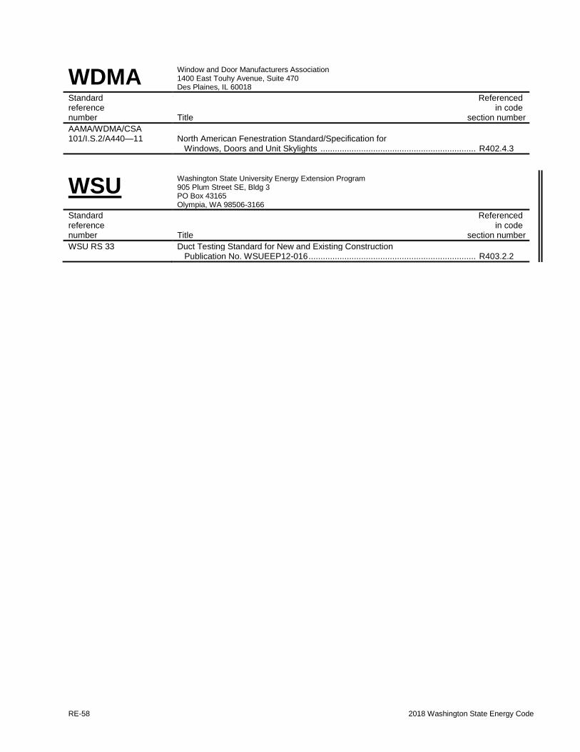
RE-58 2018 Washington State Energy Code
WDMA Window and Door Manufacturers Association 1400 East Touhy Avenue, Suite 470 Des Plaines, IL 60018
Standard Referenced reference in code number Title section number
AAMA/WDMA/CSA 101/I.S.2/A440—11 North American Fenestration Standard/Specification for Windows, Doors and Unit Skylights ................................................................. R402.4.3
WSU Washington State University Energy Extension Program 905 Plum Street SE, Bldg 3 PO Box 43165 Olympia, WA 98506-3166
Standard Referenced reference in code number Title section number
WSU RS 33 Duct Testing Standard for New and Existing Construction Publication No. WSUEEP12-016 ...................................................................... R403.2.2

2018 Washington State Energy Code RE-59
Appendix A
DEFAULT HEAT LOSS COEFFICIENTS
SECTION A101 GENERAL REQUIREMENTS
A101.1 Scope. The following defaults shall apply to
Chapter 4 of both the (RE) and (CE) sections of the
WSEC. This chapter includes tables of seasonal
average heat loss coefficients for specified nominal
insulation.
A101.2 Description. These coefficients were
developed primarily from data and procedures from
the ASHRAE Fundamentals Handbook.
Coefficients not contained in this chapter may be
computed using the procedures listed in this reference
if the assumptions in the following sections are used,
along with data from the sources referenced above.
A101.3 Air films. Default R-values used for air
films shall be as follows:
R-Value Condition
0.17 All exterior surfaces
0.61 Interior horizontal surfaces,
heat flow up
0.92 Interior horizontal surfaces,
heat flow down
0.68 Interior vertical surfaces
A101.4 Compression of Insulation: Insulation
which is compressed shall be rated in accordance
with Table A101.4 or reduction in value may be
calculated in accordance with the procedures in the
ASHRAE Fundamentals Handbook.
A101.5 Building materials. Default R-values used
for building materials shall be as shown in Table
A101.5.
TABLE A101.4 R-VALUE OF FIBERGLASS BATTS COMPRESSED WITHIN VARIOUS DEPTH CAVITIES
Insulation R-Values at Standard Thickness
Rated R-Value 82 71 60 49 38 30 22 21 19 15 13 11
Standard
Thickness, Inches 26.0 22.5 19.0 15.5 12” 9.5 6.5 5.5 6 3.5 3.5 3.5
Nominal
Lumber
Sizes,
Inches
Actual
Depth of
Cavity,
Inches
Insulation R-Values When Installed in a Confined Cavity
Truss 26.0 82 — — — — — — — — — — —
Truss 22.5 — 71 — — — — — — — — — —
Truss 19.0 — — 60 — — — — — — — — —
Truss 15.5 — — — 49 — — — — — — — —
Truss 12.0 — — — — 38 — — — — — — —
2x12 11.25 — — — — 37 — — — — — — —
2x10 9.25 — — — — 32 30 — — — — — —
2x8 7.25 — — — — 27 26 22 21 19 — — —
2x6 5.5 — — — — — 21 20 21 18 — — —
2x4 3.5 — — — — — — 14 — 13 15 13 11
2.5 — — — — — — — — — — 9.8 —
1.5 — — — — — — — — — — 6.3 6.0

RE-60 2018 Washington State Energy Code
TABLE A101.5 DEFAULT R-VALUES FOR BUILDING MATERIALS
Material Nominal
Size (in.)
Actual
Size (in.)
R-Value
(Heat Capacity3)
Air cavity (unventilated), between metal studs at 16 inches on centera - - 0.79
Air cavity (unventilated), all other depths and framing materials1 - - 0.91
Airfilm, exterior surfaces2 - - 0.17
Airfilm, interior horizontal surfaces, heat flow up2 - - 0.61
Airfilm, interior horizontal surfaces, heat flow down2 - - 0.92
Airfilm, interior vertical surfaces2 - - 0.68
Brick at R-0.12/in. (face brick, 75% solid/25% core area, 130 lbs/ft3) 4 3.5 0.32 (5.9)
Carpet and rubber pad - - 1.23
Concrete at R-0.0625/in., heavyweight (144 lbs/ft3) - 2 0.13 (HC-4.8)
- 4 0.25 (HC-9.6)
- 6 0.38 (HC-14.4)
- 8 0.50 (HC-19.2)
- 10 0.63 (HC-24.0)
- 12 0.75 (HC-28.8)
Concrete masonry units, solid grouted, lightweight (95 lbs/ft3) 6 - 0.80 (HC-11.4)
Concrete masonry units, solid grouted, normal weight (135 lbs/ft3) 6 - 0.51 (HC-13.2)
Concrete masonry units, partly grouted, lightweight (95 lbs/ft3) 6 - 1.33 (HC-6.7)
Concrete masonry units, partly grouted, normal weight (135 lbs/ft3) 6 - 0.82 (HC-9.0)
Concrete masonry units, solid grouted, lightweight (95 lbs/ft3) 8 - 1.05 (HC-15.5)
Concrete masonry units, solid grouted, normal weight (135 lbs/ft3) 8 - 0.69 (HC-17.9)
Concrete masonry units, partly grouted, lightweight (95 lbs/ft3) 8 - 1.44 (HC-9.6)
Concrete masonry units, partly grouted, normal weight (135 lbs/ft3) 8 - 0.98 (HC-12.0)
Concrete masonry units, solid grouted, lightweight (95 lbs/ft3) 10 - 1.30 (HC-19.7)
Concrete masonry units, solid grouted, normal weight (135 lbs/ft3) 10 - 0.87 (HC-22.6)
Concrete masonry units, partly grouted, lightweight (95 lbs/ft3) 10 - 1.61 (HC-11.9)
Concrete masonry units, partly grouted, normal weight (135 lbs/ft3) 10 - 1.11 (HC-14.8)
Concrete masonry units, solid grouted, lightweight (95 lbs/ft3) 12 - 1.53 (HC-23.9)
Concrete masonry units, solid grouted, normal weight (135 lbs/ft3) 12 - 1.06 (HC-27.2)
Concrete masonry units, partly grouted, lightweight (95 lbs/ft3) 12 - 1.75 (HC-14.2)
Concrete masonry units, partly grouted, normal weight (135 lbs/ft3) 12 - 1.23 (HC-17.5)
Flooring, wood subfloor - 0.75 0.94
Gypsum board - 0.5 0.45
- 0.625 0.56
Metal deck - - 0
Roofing, built-up - 0.375 0.33
Sheathing, vegetable fiber board, 0.78 in. - 0.78 2.06
Soil at R-0.104/in. - 12 1.25
Steel, mild 1 0.0031807
Stucco - 0.75 0.08
a. There is no credit for cavities that are open to outside air.
b. Air films do not apply to air cavities within an assembly.
c. For heat capacity for concrete and concrete masonry materials with densities other than the values listed in Table
A101.5, see Tables A3.1B and A3.1C in ASHRAE/IESNA Standard 90.1.

2018 Washington State Energy Code RE-61
SECTION A102 CEILINGS
A102.1 General. Table A102.1 lists heat loss
coefficients for the opaque portion of exterior
ceilings below vented attics, vaulted ceilings and roof
decks in units of Btu/h × ft2 × °F of ceiling.
They are derived from procedures listed in the
ASHRAE Fundamentals Handbook. Ceiling U-
factors are modified for the buffering effect of the
attic, assuming an indoor temperature of 65°F and an
outdoor temperature of 45°F.
A102.1.1 Metal framed ceilings. The nominal R-
values in Table A103.3.6.2: Effective R-Values
for Metal Framing and Cavity Only may be used
for purposes of calculating metal framed ceiling
section U-factors in lieu of the ASHRAE zone
calculation method as provided in Chapter 27 of
the ASHRAE Fundamentals Handbook.
Metal building roofs have a different construction
and are addressed in Table A102.2.5.
A102.2 Component description. The four types of
ceilings are characterized as follows:
A102.2.1 Ceilings below a vented attic. Attic
insulation is assumed to be blown-in, loose-fill
fiberglass with a K-value of 2.6 h × ft2 •× °F/Btu
per inch. Full bag count for specified R-value is
assumed in all cases. Ceiling dimensions for flat
ceiling calculations are 45 by 30 feet, with a gabled
roof having a 4/12 pitch. The attic is assumed to
vent naturally at the rate of 3 air changes per hour
through soffit and ridge vents. A void fraction of
0.002 is assumed for all attics with insulation
baffles. Standard-framed, unbaffled attics assume
a void fraction of 0.008.
Attic framing is either standard or advanced.
Standard framing assumes tapering of insulation
depth around the perimeter with resultant decrease
in thermal resistance. An increased R-value is
assumed in the center of the ceiling due to the
effect of piling leftover insulation. Advanced
framing assumes full and even depth of insulation
extending to the outside edge of exterior walls.
Advanced framing does not change from the
default value. U-factors for flat ceilings below
vented attics with standard framing may be
modified with the following table:
Roof Pitch U-factor for
Standard Framing
R-30 R-38
4/12 0.036 0.031
5/12 0.035 0.030
6/12 0.034 0.029
7/12 0.034 0.029
8/12 0.034 0.028
9/12 0.034 0.028
10/12 0.033 0.028
11/12 0.033 0.027
12/12 0.033 0.027
Vented scissors truss attics assume a ceiling pitch
of 2/12 with a roof pitch of either 4/12 or 5/12.
Unbaffled standard framed scissors truss attics are
assumed to have a void fraction of 0.016.
A102.2.2 Vaulted ceilings. Insulation is assumed
to be fiberglass batts installed in roof joist cavities.
In the vented case, at least 1.5 inches between the
top of the batts and the underside of the roof
sheathing is left open for ventilation in each cavity.
A ventilation rate of 3.0 air changes per hour is
assumed. In the unvented or dense pack case, the
ceiling cavity is assumed to be fully packed with
insulation, leaving no space for ventilation.
A102.2.3 Roof decks. Rigid insulation is applied
to the top of roof decking with no space left for
ventilation. Roofing materials are attached directly
on top of the insulation. Framing members are
often left exposed on the interior side.
A102.2.4 Metal truss framing. Overall system
tested values for the roof/ceiling Uo for metal
framed truss assemblies from approved laboratories
shall be used, when such data is acceptable to the
building official.
Alternatively, the Uo for roof/ceiling assemblies
using metal truss framing may be obtained from
Tables A102.2.4(1) through A102.2.4(5).
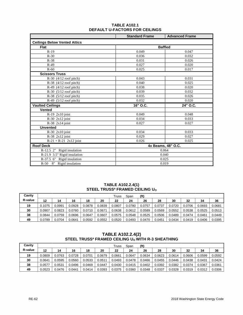
RE-62 2018 Washington State Energy Code
TABLE A102.1 DEFAULT U-FACTORS FOR CEILINGS
Standard Frame Advanced Frame
Ceilings Below Vented Attics
Flat Baffled
R-19 0.049 0.047
R-30 0.036 0.032
R-38 0.031 0.026
R-49 0.027 0.020
R-60 0.025 0.017
Scissors Truss
R-30 (4/12 roof pitch) 0.043 0.031
R-38 (4/12 roof pitch) 0.040 0.025
R-49 (4/12 roof pitch) 0.038 0.020
R-30 (5/12 roof pitch) 0.039 0.032
R-38 (5/12 roof pitch) 0.035 0.026
R-49 (5/12 roof pitch) 0.032 0.020
Vaulted Ceilings 16" O.C. 24" O.C.
Vented
R-19 2x10 joist 0.049 0.048
R-30 2x12 joist 0.034 0.033
R-38 2x14 joist 0.027 0.027
Unvented
R-30 2x10 joist 0.034 0.033
R-38 2x12 joist 0.029 0.027
R-21 + R-21 2x12 joist 0.026 0.025
Roof Deck 4x Beams, 48" O.C.
R-12.5 2" Rigid insulation 0.064
R-21.9 3.5" Rigid insulation 0.040
R-37.5 6" Rigid insulation 0.025
R-50 8" Rigid insulation 0.019
TABLE A102.2.4(1) STEEL TRUSSa FRAMED CEILING UO
Cavity Truss Span (ft)
R-value 12 14 16 18 20 22 24 26 28 30 32 34 36
19 0.1075 0.0991 0.0928 0.0878 0.0839 0.0807 0.0780 0.0757 0.0737 0.0720 0.0706 0.0693 0.0681
30 0.0907 0.0823 0.0760 0.0710 0.0671 0.0638 0.0612 0.0589 0.0569 0.0552 0.0538 0.0525 0.0513
38 0.0844 0.0759 0.0696 0.0647 0.0607 0.0575 0.0548 0.0525 0.0506 0.0489 0.0474 0.0461 0.0449
49 0.0789 0.0704 0.0641 0.0592 0.0552 0.0520 0.0493 0.0470 0.0451 0.0434 0.0419 0.0406 0.0395
TABLE A102.2.4(2) STEEL TRUSSa FRAMED CEILING UO WITH R-3 SHEATHING
Cavity Truss Span (ft)
R-value 12 14 16 18 20 22 24 26 28 30 32 34 36
19 0.0809 0.0763 0.0728 0.0701 0.0679 0.0661 0.0647 0.0634 0.0623 0.0614 0.0606 0.0599 0.0592
30 0.0641 0.0595 0.0560 0.0533 0.0511 0.0493 0.0478 0.0466 0.0455 0.0446 0.0438 0.0431 0.0424
38 0.0577 0.0531 0.0496 0.0469 0.0447 0.0430 0.0415 0.0402 0.0392 0.0382 0.0374 0.0367 0.0361
49 0.0523 0.0476 0.0441 0.0414 0.0393 0.0375 0.0360 0.0348 0.0337 0.0328 0.0319 0.0312 0.0306

2018 Washington State Energy Code RE-63
TABLE A102.2.4(3) STEEL TRUSSa FRAMED CEILING UO WITH R-5 SHEATHING
Cavity Truss Span (ft)
R-value 12 14 16 18 20 22 24 26 28 30 32 34 36
19 0.0732 0.0697 0.0670 0.0649 0.0633 0.0619 0.0608 0.0598 0.0590 0.0583 0.0577 0.0571 0.0567
30 0.0564 0.0529 0.0502 0.0481 0.0465 0.0451 0.0440 0.0430 0.0422 0.0415 0.0409 0.0403 0.0399
38 0.0501 0.0465 0.0438 0.0418 0.0401 0.0388 0.0376 0.0367 0.0359 0.0351 0.0345 0.0340 0.0335
49 0.0446 0.0410 0.0384 0.0363 0.0346 0.0333 0.0322 0.0312 0.0304 0.0297 0.0291 0.0285 0.0280
TABLE A102.2.4(4) STEEL TRUSSa FRAMED CEILING UO WITH R-10 SHEATHING
Cavity Truss Span (ft)
R-value 12 14 16 18 20 22 24 26 28 30 32 34 36
19 0.0626 0.0606 0.0590 0.0578 0.0569 0.0561 0.0555 0.0549 0.0545 0.0541 0.0537 0.0534 0.0531
30 0.0458 0.0437 0.0422 0.0410 0.0401 0.0393 0.0387 0.0381 0.0377 0.0373 0.0369 0.0366 0.0363
38 0.0394 0.0374 0.0359 0.0347 0.0337 0.0330 0.0323 0.0318 0.0313 0.0309 0.0305 0.0302 0.0299
49 0.0339 0.0319 0.0304 0.0292 0.0283 0.0275 0.0268 0.0263 0.0258 0.0254 0.0251 0.0247 0.0245
TABLE A102.2.4(5) STEEL TRUSSa FRAMED CEILING UO WITH R-15 SHEATHING
Cavity Truss Span (ft)
R-value 12 14 16 18 20 22 24 26 28 30 32 34 36
19 0.0561 0.0550 0.0541 0.0535 0.0530 0.0526 0.0522 0.0519 0.0517 0.0515 0.0513 0.0511 0.0509
30 0.0393 0.0382 0.0373 0.0367 0.0362 0.0358 0.0354 0.0351 0.0349 0.0347 0.0345 0.0343 0.0341
38 0.0329 0.0318 0.0310 0.0303 0.0298 0.0294 0.0291 0.0288 0.0285 0.0283 0.0281 0.0279 0.0278
49 0.0274 0.0263 0.0255 0.0249 0.0244 0.0239 0.0236 0.0233 0.0230 0.0228 0.0226 0.0225 0.0223
Footnotes for Tables A102.2.4(1) through A102.2.4(5)
a. Assembly values based on 24 inch on center truss spacing; 11 Truss member connections penetrating insulation (4 at
the eaves, 7 in the interior space); ½ inch drywall ceiling; all truss members are 2x4 "C" channels with a solid web.
b. Ceiling sheathing installed between bottom chord and drywall.
A102.2.5 Metal building roof. Table A102.2.5:
The base assembly is a roof where the insulation is
compressed when installed beneath metal roof
panels attached to the steel structure (purlins).
Additional assemblies include continuous
insulation, uncompressed and uninterrupted by
framing.
U-factors for metal building roofs shall be taken
from Table A102.2.5, provided the average purlin
spacing is at least 52 inches and the R-value of the
thermal spacer block is greater than or equal to the
thermal spacer block R-value indicated in Table
A107.2.5 for the assembly. It is not acceptable to
use the U-factors in Tables A102.2.6(1),
A102.2.6(2) or A102.2.6(3) if additional insulated
sheathing is not continuous.
A102.2.5.1 Single layer. The rated R-value of
insulation is for insulation installed
perpendicular to and draped over purlins and
then compressed when the metal roof panels are
attached. A minimum R-3 (R-0.5) thermal
spacer block between the purlins and the metal
roof panels is required, unless compliance is
shown by the overall assembly U-factor.
A102.2.5.2 Double layer. The first rated R-
value of insulation is for insulation installed
perpendicular to and draped over purlins. The
second rated R-value of insulation is for unfaced
insulation installed above the first layer and
parallel to the purlins and then compressed when
the metal roof panels are attached. A minimum
R-3 (R-0.5) thermal spacer block between the
purlins and the metal roof panels is required,
unless compliance is shown by the overall
assembly U-factor.
A102.2.5.3 Continuous insulation. For

RE-64 2018 Washington State Energy Code
continuous insulation (e.g., insulation boards or
blankets), it is assumed that the insulation is
installed below the purlins and is uninterrupted
by framing members. Insulation exposed to the
conditioned space or semi-heated space shall
have a facing, and all insulation seams shall be
continuously sealed to provide a continuous air
barrier.
A102.2.5.4 Liner system (Ls). A continuous
membrane is installed below the purlins and
uninterrupted by framing members.
Uncompressed, unfaced insulation rests on top of
the membrane between the purlins. For
multilayer installations, the last rated R-value of
insulation is for unfaced insulation draped over
purlins and then compressed when the metal roof
panels are attached. A minimum R-3 (R-0.5)
thermal spacer block between the purlins and the
metal roof panels is required, unless compliance
is shown by the overall assembly U-factor.
A102.2.5.5 Filled cavity. The first rated R-
value of insulation is for faced insulation
installed parallel to the purlins. The second rated
R-value of insulation is for unfaced insulation
installed above the first layer, parallel to and
between the purlins and compressed when the
metal roof panels are attached. The facer of the
first layer of insulation is of sufficient width to
be continuously sealed to the top flange of the
purlins and to accommodate the full thickness of
the second layer of insulation. A supporting
structure retains the bottom of the first layer at
the prescribed depth required for the full
thickness of the second layer of insulation being
installed above it. A minimum R-5 (R-0.9)
thermal spacer block between the purlins and the
metal roof panels is required, unless compliance
is shown by the overall assembly U-factor.
A102.2.6 Roofs with insulation entirely above
deck (uninterrupted by framing). Table
A102.2.6(1) through A102.2.6(3): The base
assembly is continuous insulation over a
structural deck. These tables indicate effective
U-factors for tapered roof insulation, sloped from
a maximum R-value (Rmax) at the peak of the
slope to a minimum R-value (Rmin) at the low
point of the slope. The rows of the tables
represent the rated R-value of the insulation at
the minimum conditions (except at roof drains)
and the columns of the table represent the rated
R-value of the insulation at the maximum
conditions. The slope of the tapered insulation
shall be no greater than 1/4 inch per foot.

2018 Washington State Energy Code RE-65
TABLE A102.2.5 DEFAULT U-FACTORS FOR METAL BUILDING ROOFS
Insulation
System
Rated R-Value
of Insulation
Overall U-Factor
for Entire Base
Roof Assembly
Overall U-Factor for Assembly of Base Roof Plus
Continuous Insulation (uninterrupted by framing)
Rated R-Value of Continuous Insulation
R-6.5 R-13 R-19.5 R-26 R-32.5 R-39
Standing Seam Roofs with Thermal Spacer Blocksa,b
Single
Layer
None 1.280 0.137 0.073 0.049 0.037 0.030 0.025
R-10 0.115 0.066 0.046 0.035 0.029 0.024 0.021
R-11 0.107 0.063 0.045 0.035 0.028 0.024 0.021
R-13 0.101 0.061 0.044 0.034 0.028 0.024 0.020
R-16 0.096 0.059 0.043 0.033 0.027 0.023 0.020
R-19 0.082 0.053 0.040 0.031 0.026 0.022 0.020
Double
Layer
R-10 .+ R-10 0.088 0.056 0.041 0.032 0.027 0.023 0.020
R-10 .+ R-11 0.086 0.055 0.041 0.032 0.027 0.023 0.020
R-11 .+ R-11 0.085 0.055 0.040 0.032 0.026 0.023 0.020
R-10 .+ R-13 0.084 0.054 0.040 0.032 0.026 0.023 0.020
R-11 .+ R-13 0.082 0.053 0.040 0.032 0.026 0.022 0.020
R-13 .+ R-13 0.075 0.050 0.038 0.030 0.025 0.022 0.019
R10 .+ R-19 0.074 0.050 0.038 0.030 0.025 0.022 0.019
R-11 .+ R-19 0.072 0.049 0.037 0.030 0.025 0.022 0.019
R-13 .+ R-19 0.068 0.047 0.036 0.029 0.025 0.021 0.019
R-16 .+ R-19 0.065 0.046 0.035 0.029 0.024 0.021 0.018
R-19 .+ R-19 0.060 0.043 0.034 0.028 0.023 0.020 0.018
Liner
System
R-19 .+ R-11 0.035
R-25 .+ R-11 0.031
R-30 .+ R-11 0.029
R-25 .+
R-11 .+ R-11
0.026
Filled Cavity with Thermal Spacer Blocksc
R-10 .+ R-19 0.057 0.042 0.033 0.027 0.023 0.020 0.018
Standing Seam Roofs without Thermal Spacer Blocks
Liner
System
R-19 .+ R-11 0.040
Thru-Fastened Roofs without Thermal Spacer Blocks
Single
Layer
R-10 0.184
R-11 0.182
R-13 0.174
R-16 0.157
R-19 0.151
Liner
System
R-19 .+ R-11 0.044
(Multiple R-values are listed in order from inside to outside)
a. A standing seam roof clip that provides a minimum 1.5 in. distance between the top of the purlins and the underside of the
metal roof panels is required.
b. A minimum R-3 thermal spacer block is required.
c. A minimum R-5 thermal spacer block is required.

RE-66 2018 Washington State Energy Code
TABLE A102.2.6(1) ASSEMBLY U-FACTORS FOR ROOFS WITH TAPERED INSULATION ENTIRELY ABOVE DECK
SINGLE SLOPE RECTANGULAR TO ONE-SIDE,d,f,g,h,i
(UNINTERRUPTED BY FRAMING)
TABLE A102.2.6(2) ASSEMBLY U-FACTORS FOR ROOFS WITH TAPERED INSULATION ENTIRELY ABOVE DECK
SLOPED TRIANGLE (ROOF WITH CENTER DRAIN)e,f,g,h,i
(UNINTERRUPTED BY FRAMING)

2018 Washington State Energy Code RE-67
TABLE A102.2.6(3) ASSEMBLY U-FACTORS FOR ROOFS WITH TAPERED INSULATION ENTIRELY ABOVE DECK
SLOPED TRIANGLE (ROOF WITH PERIMETER DRAINS)e,f,g,h,i
(UNINTERRUPTED BY FRAMING)
Footnotes to Tables A102.2.6.1, A102.2.6.2, and A102.2.6.3:
a. Rmax and Rmin are determined along the linearly tapered cross section for the respective minimum and maximum
thickness values for the roof section being analyzed. For triangular roof sections
b. Rmax refers to the insulation value along the long edge of the triangle and Rmin to the insulation at the point of the
triangle which assumes that the insulation slopes to the center.
c. Rmax refers to the insulation value at the point of the triangle and Rmin to the insulation along the long edge of the
triangle which assumes that the insulation slopes to the perimeter.
d. Effective U-factor for rectangular tapered insulation is calculated as follows:
min
max
minmax
lnR
R
RRReff
e. Effective U-factor for triangular tapered insulation is calculated as follows: 1
max
min
minmax
min
minmax
ln12
R
R
RR
R
RRReff
f. Assembly U-factors include an exterior air film (R=0.17) and an interior air film, horizontal with heat flow up
(R=0.61).
g. For effective U-factors of roof assemblies with different Rmax or Rmin values not listed in the tables interpolation is
allowed.
h. This table shall only be applied to tapered insulation that is tapered along only one axis.
i. In areas of differing insulation slopes/configurations, individual U-values shall be calculated and an area weighted U-
value calculation shall be used to determine the effective value of the roof.

RE-68 2018 Washington State Energy Code
SECTION A103 ABOVE GRADE WALLS
A103.1 General. The tables in this section list heat
loss coefficients for the opaque portion of above-
grade wood stud frame walls, metal stud frame walls
and concrete masonry walls (Btu/h × ft2 × °F). They
are derived from procedures listed in the ASHRAE
Fundamentals Handbook. For intermediate floor
slabs which penetrate the insulated wall, use the
concrete wall U-factors in Table A103.3.7.1(1).
Insulation is assumed to uniformly fill the entire
cavity and to be installed as per manufacturer's
directions. All walls are assumed to be finished on
the inside with 1/2 inch gypsum wallboard, and on
the outside with either beveled wood siding over 1/2
inch plywood sheathing or with 5/8 inch T1-11
siding. Insulated sheathing (either interior or
exterior) is assumed to cover the entire opaque wall
surface, except where modified in accordance with
footnote g to Table C402.1.3.
Metal building walls have a different construction
and are addressed in Table A103.3.6.3.
A103.2 Framing description. For wood stud frame
walls, three framing types are considered and defined
as follows:
A103.2.1 Standard. Studs framed on 16 inch
centers with double top plate and single bottom
plate. Corners use three studs and each opening is
framed using two studs. Headers consist of double
2x or single 4x material with an air space left
between the header and the exterior sheathing.
Interior partition wall/exterior wall intersections
use two studs in the exterior wall.
Standard framing weighting factors:
Studs and plates 0.19
Insulated cavity 0.77
Headers 0.04
A103.2.2 Intermediate. Studs framed on 16 inch
centers with double top plate and single bottom
plate. Corners use two studs or other means of
fully insulating corners, and each opening is
framed by two studs. Headers consist of double 2x
material with R-10 insulation. Interior partition
wall/exterior wall intersections are fully insulated
in the exterior wall.
Intermediate framing weighting factors:
Studs and plates 0.18
Insulated cavity 0.78
Headers 0.04
A103.2.3 Advanced. Studs framed on 24 inch
centers with double top plate and single bottom
plate. Corners use two studs or other means of
fully insulating corners, and one stud is used to
support each header. Headers consist of double 2x
material with R-10 insulation. Interior partition
wall/exterior wall intersections are fully insulated
in the exterior wall.
Advanced framing weighting factors:
Studs and plates 0.13
Insulated cavity 0.83
Headers 0.04
A103.3 Component description. Default
coefficients for the following types of walls are
listed: Single-stud walls, strap walls, double-stud
walls, log walls, stress-skin panels, metal stud walls,
and metal building walls.
A103.3.1 Single-stud wall. Tables A103.3.1(1)
through A103.3.1(8): Assumes either 2 x 4 or 2 x 6
studs framed on 16 or 24 inch centers. Headers are
solid for 2 x 4 walls and double 2x for 2 x 6 walls,
with either dead-air or rigid-board insulation in the
remaining space.

2018 Washington State Energy Code RE-69
TABLE A103.3.1(1) 2 x 4 Single Wood Stud: R-11 Batt Siding Material/Framing Type
R-value of Foam Board
Lapped Wood T1-11
NOTE: STD ADV STD ADV
Nominal Batt R-value: 0 0.088 0.084 0.094 0.090
R-11 at 3.5 inch thickness 1 0.080 0.077 0.085 0.082
2 0.074 0.071 0.078 0.075
Installed Batt R-value: 3 0.069 0.066 0.072 0.070
R-11 in 3.5 inch cavity 4 0.064 0.062 0.067 0.065
5 0.060 0.058 0.063 0.061
6 0.056 0.055 0.059 0.057
7 0.053 0.052 0.055 0.054
8 0.051 0.049 0.052 0.051
9 0.048 0.047 0.050 0.049
10 0.046 0.045 0.047 0.046
11 0.044 0.043 0.045 0.044
12 0.042 0.041 0.043 0.042
TABLE A103.3.1(2) 2 x 4 Single Wood Stud: R-13 Batt
Siding Material/Framing Type
R-value of Foam Board
Lapped Wood T1-11
NOTE: STD ADV STD ADV
Nominal Batt R-value: 0 0.082 0.078 0.088 0.083
R-13 at 3.63 inch thickness 1 0.075 0.072 0.080 0.076
2 0.069 0.066 0.073 0.070
Installed Batt R-value: 3 0.065 0.062 0.068 0.065
R-12.7 in 3.5 inch cavity 4 0.060 0.058 0.063 0.061
5 0.057 0.055 0.059 0.057
6 0.053 0.052 0.056 0.054
7 0.051 0.049 0.052 0.051
8 0.048 0.047 0.050 0.048
9 0.046 0.045 0.047 0.046
10 0.044 0.043 0.045 0.044
11 0.042 0.041 0.043 0.042
12 0.040 0.039 0.041 0.040

RE-70 2018 Washington State Energy Code
TABLE A103.3.1(3) 2 x 4 Single Wood Stud: R-15 Batt Siding Material/Framing Type
R-value of Foam Board
Lapped Wood T1-11
NOTE:
STD ADV STD ADV
Nominal Batt R-value: 0 0.076 0.071 0.081 0.075
R-15 at 3.5 inch thickness 1 0.069 0.065 0.073 0.069
2 0.064 0.061 0.068 0.069
Installed Batt R-value: 3 0.060 0.057 0.063 0.059
R-15 in 3.5 inch cavity 4 0.056 0.053 0.059 0.056
5 0.053 0.051 0.055 0.052
6 0.050 0.048 0.052 0.050
7 0.047 0.046 0.049 0.047
8 0.045 0.044 0.047 0.045
9 0.043 0.042 0.044 0.043
10 0.041 0.040 0.042 0.041
11 0.039 0.038 0.041 0.039
12 0.038 0.037 0.039 0.038
TABLE A103.3.1(4) 2 x 6 Single Wood Stud: R-19 Batt Siding Material/Framing Type
R-value of Foam Board
Lapped Wood T1-11
NOTE: STD INT ADV STD INT ADV
Nominal Batt R-value: 0 0.062 0.058 0.055 0.065 0.061 0.058
R-19 at 6 inch thickness 1 0.058 0.055 0.052 0.060 0.057 0.055
2 0.054 0.052 0.050 0.056 0.054 0.051
Installed Batt R-value: 3 0.051 0.049 0.047 0.053 0.051 0.049
R-18 in 5.5 inch cavity 4 0.048 0.046 0.045 0.050 0.048 0.046
5 0.046 0.044 0.043 0.048 0.046 0.044
6 0.044 0.042 0.041 0.045 0.044 0.042
7 0.042 0.040 0.039 0.043 0.042 0.040
8 0.040 0.039 0.038 0.041 0.040 0.039
9 0.038 0.037 0.035 0.039 0.038 0.037
10 0.037 0.036 0.035 0.038 0.037 0.036
11 0.036 0.035 0.034 0.036 0.035 0.035
12 0.034 0.033 0.033 0.035 0.034 0.033

2018 Washington State Energy Code RE-71
TABLE A103.3.1(5) 2 x 6 Single Wood Stud: R-21 Batt
Siding Material/Framing Type
R-value of
Foam Board
Lapped Wood T1-11
NOTE: STD INT ADV STD INT ADV
Nominal Batt R-value: 0 0.057 0.054 0.051 0.060 0.056 0.053
R-21 at 5.5 inch thickness 1 0.054 0.051 0.048 0.056 0.053 0.050
2 0.050 0.048 0.045 0.052 0.050 0.047
Installed Batt R-value: 3 0.048 0.045 0.043 0.049 0.047 0.045
R-21 in 5.5 inch cavity 4 0.045 0.043 0.041 0.047 0.045 0.043
5 0.043 0.041 0.040 0.044 0.042 0.041
6 0.041 0.039 0.038 0.042 0.041 0.039
7 0.039 0.038 0.036 0.040 0.039 0.037
8 0.038 0.036 0.035 0.039 0.037 0.036
9 0.036 0.035 0.034 0.037 0.036 0.035
10 0.035 0.034 0.033 0.036 0.035 0.033
11 0.033 0.033 0.032 0.034 0.033 0.032
12 0.032 0.031 0.031 0.033 0.032 0.031
TABLE A103.3.1(6) 2 x 6 Single Wood Stud: R-22 Batt
Siding Material/Framing Type
R-value of
Foam Board
Lapped Wood T1-11
NOTE: STD INT ADV STD INT ADV
Nominal Batt R-value: 0 0.059 0.055 0.052 0.062 0.058 0.054
R-22 at 6.75 inch thickness 1 0.055 0.052 0.049 0.057 0.054 0.051
2 0.052 0.049 0.047 0.054 0.051 0.048
Installed Batt R-value: 3 0.049 0.046 0.044 0.050 0.048 0.046
R-20 in 5.5 inch cavity 4 0.046 0.044 0.042 0.048 0.046 0.044
5 0.044 0.042 0.041 0.045 0.043 0.042
6 0.042 0.040 0.039 0.043 0.042 0.040
7 0.040 0.039 0.037 0.041 0.040 0.038
8 0.038 0.037 0.036 0.039 0.038 0.037
9 0.037 0.036 0.035 0.038 0.037 0.035
10 0.035 0.034 0.033 0.036 0.035 0.034
11 0.034 0.033 0.032 0.035 0.034 0.033
12 0.033 0.032 0.031 0.034 0.033 0.032

RE-72 2018 Washington State Energy Code
TABLE A103.3.1(7) 2 x 6 Single Wood Stud: Two R-11 Batts
Siding Material/Framing Type
R-value of
Foam Board
Lapped Wood T1-11
NOTE: STD INT ADV STD INT ADV
Nominal Batt R-value: 0 0.060 0.057 0.054 0.063 0.059 0.056
R-22 at 7 inch thickness 1 0.056 0.053 0.051 0.059 0.056 0.053
2 0.053 0.050 0.048 0.055 0.052 0.050
Installed Batt R-value: 3 0.050 0.048 0.046 0.052 0.049 0.047
R-18.9 in 5.5 inch cavity 4 0.047 0.045 0.044 0.049 0.047 0.045
5 0.045 0.043 0.042 0.046 0.045 0.043
6 0.043 0.041 0.040 0.044 0.043 0.041
7 0.041 0.040 0.038 0.042 0.041 0.039
8 0.039 0.038 0.037 0.040 0.039 0.038
9 0.038 0.037 0.036 0.039 0.038 0.036
10 0.036 0.035 0.034 0.037 0.036 0.035
11 0.035 0.034 0.033 0.036 0.035 0.034
12 0.034 0.033 0.032 0.034 0.034 0.033
TABLE A103.3.1(8) 2 x 8 Single Stud: R-25 Batt
Siding Material/Framing Type
R-value of
Foam Board
Lapped Wood T1-11
NOTE: STD INT ADV STD INT ADV
Nominal Batt R-value: 0 0.051 0.047 0.045 0.053 0.049 0.046
R-25 at 8 inch thickness 1 0.048 0.045 0.043 0.049 0.046 0.044
2 0.045 0.043 0.041 0.047 0.044 0.042
Installed Batt R-value: 3 0.043 0.041 0.039 0.044 0.042 0.040
R-23.6 in 7.25 inch cavity 4 0.041 0.039 0.037 0.042 0.040 0.038
5 0.039 0.037 0.036 0.040 0.038 0.037
6 0.037 0.036 0.035 0.038 0.037 0.036
7 0.036 0.035 0.033 0.037 0.035 0.034
8 0.035 0.033 0.032 0.035 0.034 0.033
9 0.033 0.032 0.031 0.034 0.033 0.032
10 0.032 0.031 0.030 0.033 0.032 0.031
11 0.031 0.030 0.029 0.032 0.031 0.030
12 0.030 0.029 0.028 0.031 0.030 0.029

2018 Washington State Energy Code RE-73
A103.3.2 Strap wall. Table A103.3.2: Assumes
2 x 6 studs framed on 16 or 24 inch centers. 2 x 3
or 2 x 4 strapping is run horizontally along the
interior surface of the wall to provide additional
space for insulation.
A103.3.3 Double stud wall. Tables A103.3.3(1)
and A103.3.3(2): Assumes an exterior structural
wall and a separate interior, nonstructural wall.
Insulation is placed in both wall cavities and in the
space between the two walls. Stud spacing is
assumed to be on 24 inch centers for both walls.
A103.3.4 Log wall. U-factors for log walls shall
be determined using ICC 400 Table 305.3.1.1, U-
Factor of Log Wall (UW) by Log Thickness (WL)
and Specific Gravity.
A103.3.5 Stress-skin panel. See Table A103.3.5.
TABLE A103.3.2 2 X 6: STRAP WALL
Siding Material/Frame Type
Lapped Wood T1-11
STD ADV STD ADV
R-19 + R-11 Batts 0.036 0.035 0.038 0.036
R-19 + R-8 Batts 0.041 0.039 0.042 0.040
TABLE A103.3.3(1) 2 X 6 + 2 X 4: DOUBLE WOOD STUD
Siding Material/Frame Type
Batt Configuration Lapped Wood T1-11
Exterior Middle Interior STD ADV STD ADV
R-19 -- R-11 0.040 0.037 0.041 0.038
R-19 -- R-19 0.034 0.031 0.035 0.032
R-19 R-8 R-11 0.029 0.028 0.031 0.029
R-19 R-11 R-11 0.027 0.026 0.028 0.027
R-19 R-11 R-19 0.024 0.023 0.025 0.023
R-19 R-19 R-19 0.021 0.020 0.021 0.020
TABLE A103.3.3(2) 2 X 4 + 2 X 4: DOUBLE WOOD STUD
Siding Material/Frame Type
Batt Configuration Lapped Wood T1-11
Exterior Middle Interior STD ADV STD ADV
R-11 -- R-11 0.050 0.046 0.052 0.048
R-19 -- R-11 0.039 0.037 0.043 0.039
R-11 R-8 R-11 0.037 0.035 0.036 0.036
R-11 R-11 R-11 0.032 0.031 0.033 0.032
R-13 R-13 R-13 0.029 0.028 0.029 0.028
R-11 R-19 R-11 0.026 0.026 0.027 0.026

AE-74 2018 Washington State Energy Code
TABLE A103.3.5 STRESS SKIN PANEL
NOTE: R-value of expanded
polystyrene: R-3.85
per inch
Framing: 6%
Spline: 8%
Panel Thickness,
Inches
U-factor
3 1/2 0.071
5 1/2 0.048
7 1/4 0.037
9 1/4 0.030
11 1/4 0.025
No thermal bridging between interior and exterior splines
A103.3.6 Metal stud walls. The nominal R-values
in Tables A103.3.6.1 through A103.3.6.3 may be
used for purposes of calculating metal stud wall
section U-factors in lieu of the ASHRAE zone
calculation method as provided in Chapter 27 of
the ASHRAE Fundamentals Handbook.
A103.3.6.1 Metal stud wall, overall assembly
U-factors. Tables A103.3.6.1(1) and
A103.6.1(2): Assumes metal studs spaced on 16
or 24 inch centers with insulation installed to fill
wall cavities. Continuous rigid board insulation
is applied without creating uninsulated voids in
the wall assembly.
A103.3.6.2 Metal stud wall, effective R-values
for metal framing and cavity only. Table
A103.3.6.2: These values may be used for the
metal-framing/cavity layers in walls with metal
studs spaced on 16- or 24-inch centers with
insulation installed to fill wall cavities in lieu of
using the zone method provided in Chapter 25 of
the ASHRAE Fundamentals Handbook.
A103.3.6.3 Metal building wall. Table
A103.3.6.3: A wall whose structure consists of
metal spanning panels supported by steel
structural members (does not include spandrel
glass or metal panels in curtain wall systems).
The first nominal R-value is for insulation
compressed between metal wall panels and the
steel structure. For double-layer installations,
the second rated R-value of insulation is for
insulation installed from the inside, covering the
girts. For continuous insulation (e.g., insulation
boards) it is assumed that the insulation boards
are installed on the inside of the girts and
uninterrupted by the framing members.
Insulation exposed to the conditioned space or
semi-heated space shall have a facing, and all
insulation seams shall be continuously sealed to
provide a continuous air barrier.
A103.3.7 Concrete and masonry walls.
A103.3.7.1 Concrete masonry walls. The
nominal R-values in Tables A103.3.7.1(1) and
A103.3.7.1(2) may be used for purposes of
calculating concrete masonry wall section U-
factors in lieu of the ASHRAE isothermal planes
calculation method as provided in Chapter 27 of
the ASHRAE Fundamentals Handbook
A103.3.7.2 Peripheral edges of intermediate
concrete floors. See Table A103.3.7.2.
.

2018 Washington State Energy Code RE-75
TABLE A103.3.6.1(1) OVERALL ASSEMBLY U-FACTORS
FOR METAL STUD WALLS WITH CONTINUOUS INSULATION
R-Value of Cavity Insulation
Metal Framing
Continuous Foam Board
Insulation R-0 R-11 R-13 R-15 R-19 R-21
16” o.c.
R-0 (none)
0.352
0.132
0.124
0.118
0.109
0.106
R-1 0.260 0.117 0.111 0.106 0.099 0.096
R-2 0.207 0.105 0.100 0.096 0.090 0.087
R-3 0.171 0.095 0.091 0.087 0.082 0.080
R-4 0.146 0.087 0.083 0.080 0.076 0.074
R-5 0.128 0.080 0.077 0.074 0.071 0.069
R-6 0.113 0.074 0.071 0.069 0.066 0.065
R-7 0.102 0.069 0.066 0.065 0.062 0.061
R-8 0.092 0.064 0.062 0.061 0.058 0.057
R-9 0.084 0.060 0.059 0.057 0.055 0.054
R-10 0.078 0.057 0.055 0.054 0.052 0.051
R-11 0.072 0.054 0.052 0.051 0.050 0.049
R-12 0.067 0.051 0.050 0.049 0.047 0.047
R-13 0.063 0.049 0.048 0.047 0.045 0.045
R-14 0.059 0.046 0.045 0.045 0.043 0.043
R-15 0.056 0.044 0.043 0.043 0.041 0.041
R-20 0.044 0.036 0.036 0.035 0.034 0.034
24” o.c
R-0 (none)
0.338
0.116
0.108
0.102
0.094
0.090
R-1 0.253 0.104 0.098 0.092 0.086 0.083
R-2 0.202 0.094 0.089 0.084 0.079 0.077
R-3 0.168 0.086 0.082 0.078 0.073 0.071
R-4 0.144 0.079 0.075 0.072 0.068 0.066
R-5 0.126 0.073 0.070 0.067 0.064 0.062
R-6 0.112 0.068 0.066 0.063 0.060 0.059
R-7 0.100 0.064 0.062 0.059 0.057 0.055
R-8 0.091 0.060 0.058 0.056 0.054 0.052
R-9 0.084 0.057 0.055 0.053 0.051 0.050
R-10 0.077 0.054 0.052 0.050 0.048 0.048
R-11 0.072 0.051 0.049 0.048 0.046 0.045
R-12 0.067 0.048 0.047 0.046 0.044 0.043
R-13 0.063 0.046 0.045 0.044 0.042 0.042
R-14 0.059 0.044 0.043 0.042 0.041 0.040
R-15 0.056 0.042 0.041 0.040 0.039 0.038
R-20 0.044 0.035 0.034 0.034 0.033 0.032
Continuous foam board insulation: Continuous insulation assumes no thermal bridging of insulation by framing or z-furring
through applied foam board. Zone calculation method as provided in the ASHRAE Fundamentals Handbook must be used for
thermally bridged foam board insulation. Values for attachment of insulation with z-furring are given in Table A103.3.6.1(2).

AE-76 2018 Washington State Energy Code
TABLE A105.3.6.1(2) OVERALL ASSEMBLY U-FACTORS FOR METAL STUD WALLS
WITH INSULATION SUPPORTED BY Z-FURRING
Metal Framing
R-value of Foam Board
Insulation
Z-furring Attachment
Cavity Insulation
R-0 R-11 R-13 R-15 R-19 R-21
16” o.c. R-0 (none) Horizontal 0.352 0.132 0.124 0.118 0.109 0.106
R-5 Horizontal 0.155 0.089 0.086 0.083 0.078 0.077
R-7.5 Horizontal 0.128 0.080 0.077 0.074 0.071 0.069
R-10 Horizontal 0.110 0.072 0.070 0.068 0.065 0.064
R-12.5 Horizontal 0.099 0.068 0.065 0.064 0.061 0.060
R-15 Horizontal 0.091 0.064 0.062 0.060 0.058 0.057
R-17.5 Horizontal 0.084 0.060 0.058 0.057 0.055 0.054
R-20 Horizontal 0.078 0.057 0.056 0.054 0.052 0.052
R-22.5 Horizontal 0.074 0.055 0.054 0.052 0.051 0.050
R-25 Horizontal 0.071 0.053 0.052 0.051 0.049 0.048
R-0 (none) Vertical 0.352 0.132 0.124 0.118 0.109 0.106
R-5 Vertical 0.165 0.093 0.089 0.086 0.081 0.079
R-7.5 Vertical 0.142 0.085 0.081 0.079 0.075 0.073
R-10 Vertical 0.126 0.079 0.076 0.074 0.070 0.069
R-12.5 Vertical 0.115 0.074 0.072 0.070 0.066 0.065
R-15 Vertical 0.107 0.071 0.069 0.067 0.064 0.063
R-17.5 Vertical 0.100 0.068 0.065 0.064 0.061 0.060
R-20 Vertical 0.094 0.065 0.063 0.061 0.059 0.058
R-22.5 Vertical 0.090 0.063 0.061 0.060 0.057 0.056
R-25 Vertical 0.086 0.061 0.059 0.058 0.056 0.055
24” o.c. R-0 (none) Horizontal 0.338 0.116 0.108 0.102 0.094 0.09
R-5 Horizontal 0.152 0.082 0.078 0.074 0.070 0.068
R-7.5 Horizontal 0.126 0.074 0.070 0.068 0.064 0.062
R-10 Horizontal 0.109 0.067 0.065 0.062 0.059 0.058
R-12.5 Horizontal 0.098 0.063 0.061 0.059 0.056 0.055
R-15 Horizontal 0.090 0.060 0.058 0.056 0.053 0.052
R-17.5 Horizontal 0.083 0.057 0.055 0.053 0.051 0.050
R-20 Horizontal 0.078 0.054 0.052 0.051 0.049 0.048
R-22.5 Horizontal 0.074 0.052 0.050 0.049 0.047 0.046
R-25 Horizontal 0.070 0.050 0.049 0.047 0.046 0.045
R-0 (none) Vertical 0.338 0.116 0.108 0.102 0.094 0.09
R-5 Vertical 0.162 0.084 0.080 0.077 0.072 0.070
R-7.5 Vertical 0.140 0.078 0.074 0.071 0.067 0.065
R-10 Vertical 0.124 0.073 0.070 0.067 0.063 0.062
R-12.5 Vertical 0.113 0.069 0.066 0.064 0.061 0.059
R-15 Vertical 0.106 0.066 0.063 0.061 0.058 0.057
R-17.5 Vertical 0.098 0.063 0.061 0.059 0.056 0.055
R-20 Vertical 0.093 0.061 0.059 0.057 0.054 0.053
R-22.5 Vertical 0.089 0.059 0.057 0.055 0.053 0.051
R-25 Vertical 0.085 0.057 0.055 0.054 0.051 0.050
Values may in Table A105.3.6.1(2) may not interpolated between. The value of the foam board insulation must meet exceed the
value listed in the table in order to use the value shown.

2018 Washington State Energy Code RE-77
TABLE A103.3.6.2 EFFECTIVE R-VALUES FOR METAL FRAMING AND CAVITY ONLY
Cavity Insulation
Nominal Depth, Inches
Actual Depth, Inches
Nominal R-Value
Effective R-Value
16” O.C. 24” O.C.
Air Cavity Any Any R-0.91 (air) 0.79 0.91
Wall
4 3-1/2 R-11 5.5 6.6
4 3-1/2 R-13 6.0 7.2
4 3-1/2 R-15 6.4 7.8
6 5-1/2 R-19 7.1 8.6
6 5-1/2 R-21 7.4 9.0
8 7-1/4 R-25 7.8 9.6
Roof
Insulation is
uncompressed
R-11 5.5 6.1
R-19 7.0 9.1
R-30 9.3 11.4
TABLE A103.3.6.3 DEFAULT METAL BUILDING WALL U-FACTORS
Insulation System
Rated R-Value of
Insulation
Overall U-fFactor for
Entire Base Wall Assembly
Overall U-Factor for Assembly of Base Wall Plus Continuous Insulation (Uninterrupted by Framing)
R-6.5 R-13 R-19.5 R-26 R-32.5 R-39
Single Layer of Mineral Fiber
None 1.180 0.136 0.072 0.049 0.037 0.030 0.025
R-10 0.186 0.084 0.054 0.040 0.032 0.026 0.023
R-11 0.185 0.084 0.054 0.040 0.032 0.026 0.023
R-13 0.162 0.079 0.052 0.039 0.031 0.026 0.022
R-16 0.155 0.077 0.051 0.039 0.031 0.026 0.022
R-19 0.147 0.075 0.050 0.038 0.030 0.025 0.022

AE-78 2018 Washington State Energy Code
TABLE A103.3.7.1(1) DEFAULT U-FACTORS FOR CONCRETE AND MASONRY WALLS
8" Concrete Masonry
WALL DESCRIPTION CORE TREATMENT
Partial Grout with Ungrouted Cores
Solid Grout Empty
Loose-fill insulated
Perlite Vermiculite
Exposed Block, Both Sides 0.40 0.23 0.24 0.43
R-5 Interior Insulation, Wood Furring 0.14 0.11 0.12 0.15
R-6 Interior Insulation, Wood Furring 0.14 0.11 0.11 0.14
R-10.5 Interior Insulation, Wood Furring 0.11 0.09 0.09 0.11
R-8 Interior Insulation, Metal Clips 0.11 0.09 0.09 0.11
R-6 Exterior Insulation 0.12 0.10 0.10 0.12
R-10 Exterior Insulation 0.08 0.07 0.07 0.08
R-9.5 Rigid Polystyrene Integral Insulation, Two
Webbed Block
0.11
0.09
0.09
0.12
12" Concrete Masonry
WALL DESCRIPTION CORE TREATMENT
Partial Grout with Ungrouted Cores
Solid Grout Empty
Loose-fill insulated
Perlite Vermiculite
Exposed Block, Both Sides 0.35 0.17 0.18 0.33
R-5 Interior Insulation, Wood Furring 0.14 0.10 0.10 0.13
R-6 Interior Insulation, Wood Furring 0.13 0.09 0.10 0.13
R-10.5 Interior Insulation, Wood Furring 0.11 0.08 0.08 0.10
R-8 Interior Insulation, Metal Clips 0.10 0.08 0.08 0.09
R-6 Exterior Insulation 0.11 0.09 0.09 0.11
R-10 Exterior Insulation 0.08 0.06 0.06 0.08
R-9.5 Rigid Polystyrene Integral Insulation,
Two Webbed Block 0.11 0.08 0.09 0.12
8" Clay Brick
WALL DESCRIPTION CORE TREATMENT
Partial Grout with Ungrouted Cores
Solid Grout Empty
Loose-fill insulated
Perlite Vermiculite
Exposed Block, Both Sides 0.50 0.31 0.32 0.56
R-5 Interior Insulation, Wood Furring 0.15 0.13 0.13 0.16
R-6 Interior Insulation, Wood Furring 0.15 0.12 0.12 0.15
R-10.5 Interior Insulation, Wood Furring 0.12 0.10 0.10 0.12
R-8 Interior Insulation, Metal Clips 0.11 0.10 0.10 0.11
R-6 Exterior Insulation 0.12 0.11 0.11 0.13
R-10 Exterior Insulation 0.08 0.08 0.08 0.09

2018 Washington State Energy Code RE-79
TABLE A103.3.7.1(1) – continued DEFAULT U-FACTORS FOR CONCRETE AND MASONRY WALLS
6" Concrete Poured or Precast
WALL DESCRIPTION CORE TREATMENT
Partial Grout with Ungrouted Cores
Solid Grout Empty
Loose-fill insulated
Perlite Vermiculite
Exposed Concrete, Both Sides NA NA NA 0.61
R-5 Interior Insulation, Wood Furring NA NA NA 0.16
R-6 Interior Insulation, Wood Furring NA NA NA 0.15
R-10.5 Interior Insulation, Wood Furring NA NA NA 0.12
R-8 Interior Insulation, Metal Clips NA NA NA 0.12
R-6 Exterior Insulation NA NA NA 0.13
R-10 Exterior Insulation NA NA NA 0.09
1. Grouted cores at 40" x 48" on center vertically and horizontally in partial grouted walls.
2. Interior insulation values include 1/2" gypsum board on the inner surface.
3. Furring and stud spacing is 16" on center. Insulation is assumed to fill furring space and is not compressed.
4. Intermediate values may be interpolated using this table. Values not contained in this table may be computed using the
procedures listed in the ASHRAE Fundamentals Handbook.
5. Concrete Masonry Unit (CMU) assembly U-values are based on local test data for Washington state CMU block material
using the ASTM C-236-87 steady state thermal conductance test. Tests included an 8"x8"x16" CMU with all cells filled
with vermiculite (1995) and 8"x8"x16" CMU with all cells filled with polymaster foam in place insulation (1996).
Refer to ASHRAE Standard 90.1 for additional nationally recognized data on the thermal performance of
CMU block walls.
TABLE A103.3.7.1(2) DEFAULT U-FACTORS FOR CONCRETE AND MASONRY WALLSa,b,c,d
Framing Type and Depth
Rated R-Value of Insulation Alone
Assembly U-Factors for Solid Concrete
Walls
Assembly U-Factors for Concrete Block
Walls: Solid Grouted
Assembly U-Factors for Concrete Block Walls:
Partially Grouted (cores uninsulated
except where specified)
Base Wall only
No Framing R-0 U-0.740 U-0.580 U-0.480
Ungrouted Cores Filled
with Loose-Fill
Insulation
N.A. N.A. U-0.350
Continuous Wood Framing
0.75 in. R-3.0 U-0.247 U-0.226 U-0.210
1.5 in. R-6.0 U-0.160 U-0.151 U-0.143
2.0 in. R-10.0 U-0.116 U-0.111 U-0.107
3.5 in. R-11.0 U-0.094 U-0.091 U-0.088
3.5 in. R-13.0 U-0.085 U-0.083 U-0.080
3.5 in. R-15.0 U-0.079 U-0.077 U-0.075
5.5 in. R-19.0 U-0.060 U-0.059 U-0.058
5.5 in. R-21.0 U-0.057 U-0.055 U-0.054
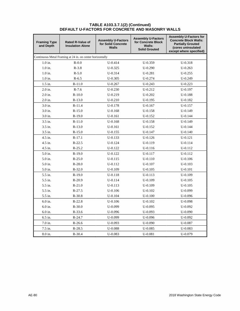
AE-80 2018 Washington State Energy Code
TABLE A103.3.7.1(2) (Continued) DEFAULT U-FACTORS FOR CONCRETE AND MASONRY WALLS
Framing Type and Depth
Rated R-Value of Insulation Alone
Assembly U-Factors for Solid Concrete
Walls
Assembly U-Factors for Concrete Block
Walls: Solid Grouted
Assembly U-Factors for Concrete Block Walls:
Partially Grouted (cores uninsulated
except where specified)
Continuous Metal Framing at 24 in. on center horizontally
1.0 in. R-0.0 U-0.414 U-0.359 U-0.318
1.0 in. R-3.8 U-0.325 U-0.290 U-0.263
1.0 in. R-5.0 U-0.314 U-0.281 U-0.255
1.0 in. R-6.5 U-0.305 U-0.274 U-0.249
1.5 in. R-11.0 U-0.267 U-0.243 U-0.223
2.0 in. R-7.6 U-0.230 U-0.212 U-0.197
2.0 in. R-10.0 U-0.219 U-0.202 U-0.188
2.0 in. R-13.0 U-0.210 U-0.195 U-0.182
3.0 in. R-11.4 U-0.178 U-0.167 U-0.157
3.0 in. R-15.0 U-0.168 U-0.158 U-0.149
3.0 in. R-19.0 U-0.161 U-0.152 U-0.144
3.5 in. R-11.0 U-0.168 U-0.158 U-0.149
3.5 in. R-13.0 U-0.161 U-0.152 U-0.144
3.5 in. R-15.0 U-0.155 U-0.147 U-0.140
4.5 in. R-17.1 U-0.133 U-0.126 U-0.121
4.5 in. R-22.5 U-0.124 U-0.119 U-0.114
4.5 in. R-25.2 U-0.122 U-0.116 U-0.112
5.0 in. R-19.0 U-0.122 U-0.117 U-0.112
5.0 in. R-25.0 U-0.115 U-0.110 U-0.106
5.0 in. R-28.0 U-0.112 U-0.107 U-0.103
5.0 in. R-32.0 U-0.109 U-0.105 U-0.101
5.5 in. R-19.0 U-0.118 U-0.113 U-0.109
5.5 in. R-20.9 U-0.114 U-0.109 U-0.105
5.5 in. R-21.0 U-0.113 U-0.109 U-0.105
5.5 in. R-27.5 U-0.106 U-0.102 U-0.099
5.5 in. R-30.8 U-0.104 U-0.100 U-0.096
6.0 in. R-22.8 U-0.106 U-0.102 U-0.098
6.0 in. R-30.0 U-0.099 U-0.095 U-0.092
6.0 in. R-33.6 U-0.096 U-0.093 U-0.090
6.5 in. R-24.7 U-0.099 U-0.096 U-0.092
7.0 in. R-26.6 U-0.093 U-0.090 U-0.087
7.5 in. R-28.5 U-0.088 U-0.085 U-0.083
8.0 in. R-30.4 U-0.083 U-0.081 U-0.079

2018 Washington State Energy Code RE-81
TABLE A103.3.7.1(4) – continued DEFAULT U-FACTORS FOR CONCRETE AND MASONRY WALLS
Framing Type and Depth
Rated R-Value of Insulation Alone
Assembly U-Factors for Solid Concrete
Walls
Assembly U-Factors for Concrete Block
Walls: Solid Grouted
Assembly U-Factors for Concrete Block Walls:
Partially Grouted (cores uninsulated
except where specified)
1 in Metal Clips at 24 in. on center horizontally and 16 in. vertically (also, where allowed by Section C402.1.3, for assemblies with a ratio of metal penetration area/ mass wall area of <0.0004 or <0.04% of
the mass wall area)5
1.0 in. R-3.8 U-0.210 U-0.195 U-0.182
1.0 in. R-5.0 U-0.184 U-0.172 U-0.162
1.0 in. R-5.6 U-0.174 U-0.163 U-0.154
1.5 in. R-5.7 U-0.160 U-0.151 U-0.143
1.5 in. R-7.5 U-0.138 U-0.131 U-0.125
1.5 in. R-8.4 U-0.129 U-0.123 U-0.118
2.0 in. R-7.6 U-0.129 U-0.123 U-0.118
2.0 in. R-10.0 U-0.110 U-0.106 U-0.102
2.0 in. R-11.2 U-0.103 U-0.099 U-0.096
2.5 in. R-9.5 U-0.109 U-0.104 U-0.101
2.5 in. R-12.5 U-0.092 U-0.089 U-0.086
2.5 in. R-14.0 U-0.086 U-0.083 U-0.080
3.0 in. R-11.4 U-0.094 U-0.090 U-0.088
3.0 in. R-15.0 U-0.078 U-0.076 U-0.074
3.0 in. R-16.8 U-0.073 U-0.071 U-0.069
3.5 in. R-13.3 U-0.082 U-0.080 U-0.077
3.5 in. R-17.5 U-0.069 U-0.067 U-0.065
3.5 in. R-19.6 U-0.064 U-0.062 U-0.061
4.0 in. R-15.2 U-0.073 U-0.071 U-0.070
4.0 in. R-20.0 U-0.061 U-0.060 U-0.058
4.0 in. R-22.4 U-0.057 U-0.056 U-0.054
5.0 in. R-28.0 U-0.046 U-0.046 U-0.045
6.0 in. R-33.6 U-0.039 U-0.039 U-0.038
7.0 in. R-39.2 U-0.034 U-0.034 U-0.033
8.0 in. R-44.8 U-0.030 U-0.030 U-0.029
9.0 in. R-50.4 U-0.027 U-0.027 U-0.026
10.0 in. R-56.0 U-0.024 U-0.024 U-0.024
11.0 in. R-61.6 U-0.022 U-0.022 U-0.022
Continuous Insulation Uninterrupted by Framing
No Framing R-1.0 U-0.425 U-0.367 U-0.324
R-2.0 U-0.298 U-0.269 U-0.245
R-3.0 U-0.230 U-0.212 U-0.197
R-4.0 U-0.187 U-0.175 U-0.164
R-5.0 U-0.157 U-0.149 U-0.141

AE-82 2018 Washington State Energy Code
TABLE A103.3.7.1(2) – continued DEFAULT U-FACTORS FOR CONCRETE AND MASONRY WALLS
Framing Type and Depth
Rated R-Value of Insulation Alone
Assembly U-Factors for Solid Concrete
Walls
Assembly U-Factors for Concrete Block
Walls: Solid Grouted
Assembly U-Factors for Concrete Block Walls:
Partially Grouted (cores uninsulated
except where specified)
No Framing R-6.0 U-0.136 U-0.129 U-0.124
R-7.0 U-0.120 U-0.115 U-0.110
R-8.0 U-0.107 U-0.103 U-0.099
R-9.0 U-0.097 U-0.093 U-0.090
R-10.0 U-0.088 U-0.085 U-0.083
No Framing R-11.0 U-0.081 U-0.079 U-0.076
R-12.0 U-0.075 U-0.073 U-0.071
R-13.0 U-0.070 U-0.068 U-0.066
R-14.0 U-0.065 U-0.064 U-0.062
R-15.0 U-0.061 U-0.060 U-0.059
No Framing R-16.0 U-0.058 U-0.056 U-0.055
R-17.0 U-0.054 U-0.053 U-0.052
R-18.0 U-0.052 U-0.051 U-0.050
R-19.0 U-0.049 U-0.048 U-0.047
R-20.0 U-0.047 U-0.046 U-0.045
No Framing R-21.0 U-0.045 U-0.044 U-0.043
R-22.0 U-0.043 U-0.042 U-0.042
R-3.0 U-0.041 U-0.040 U-0.040
R-24.0 U-0.039 U-0.039 U-0.038
R-25.0 U-0.038 U-0.037 U-0.037
No Framing R-30.0 U-0.032 U-0.032 U-0.031
R-35.0 U-0.028 U-0.027 U-0.027
R-40.0 U-0.024 U-0.024 U-0.024
R-45.0 U-0.022 U-0.021 U-0.021
R-50.0 U-0.019 U-0.019 U-0.019
R-55.0 U-0.018 U-0.018 U-0.018
R-60.0 U-0.016 U-0.016 U-0.016
Brick cavity wall with continuous insulation
No Framing R-0.0 U-0.337 U-0.299 U-0.270
No Framing R-3.8 U-0.148 U-0.140 U-0.133
No Framing R-5.0 U-0.125 U-0.120 U-0.115
No Framing R-6.5 U-0.106 U-0.102 U-0.098
No Framing R-7.6 U-0.095 U-0.091 U-0.088
No Framing R-10.0 U-0.077 U-0.075 U-0.073
No Framing R-10.5 U-0.079 U-0.077 U-0.075
No Framing R-11.4 U-0.070 U-0.068 U-0.066
No Framing R-15.0 U-0.056 U-0.055 U-0.053
No Framing R-16.5 U-0.054 U-0.053 U-0.052
No Framing R-19.0 U-0.046 U-0.045 U-0.044
No Framing R-22.5 U-0.041 U-0.040 U-0.039
No Framing R-28.5 U-0.033 U-0.032 U-0.032

2018 Washington State Energy Code RE-83
TABLE A103.3.7.1(2) – continued DEFAULT U-FACTORS FOR CONCRETE AND MASONRY WALLS
Framing Type and Depth
Rated R-Value of Insulation Alone
Assembly U-Factors for Solid Concrete
Walls
Assembly U-Factors for Concrete Block
Walls: Solid Grouted
Assembly U-Factors for Concrete Block Walls:
Partially Grouted (cores uninsulated
except where specified)
Continuous Insulation Uninterrupted by Framing with Stucco and Continuous Metal Framing at 24 in. on center horizontally
1.0 in. R-0.0 + R-19 c.i. U-0.047 U-0.046 U-0.045
1.0 in. R-3.8 + R-19 c.i. U-0.045 U-0.044 U-0.044
1.0 in. R-5.0 + R-19 c.i. U-0.045 U-0.044 U-0.043
1.0 in. R-6.5 + R-19 c.i. U-0.045 U-0.044 U-0.043
1.5 in. R-11.0 + R-19 c.i. U-0.044 U-0.043 U-0.043
2.0 in. R-7.6 + R-19 c.i. U-0.043 U-0.042 U-0.041
2.0 in. R-10.0 + R-19 c.i. U-0.042 U-0.041 U-0.041
2.0 in. R-13.0 + R-19 c.i. U-0.042 U-0.041 U-0.041
3.0 in. R-11.4 + R-19 c.i. U-0.041 U-0.040 U-0.039
3.0 in. R-15.0 + R-19 c.i. U-0.040 U-0.039 U-0.039
3.0 in. R-19.0 + R-19 c.i. U-0.040 U-0.039 U-0.038
3.5 in. R-11.0 + R-19 c.i. U-0.040 U-0.039 U-0.039
3.5 in. R-13.0 + R-19 c.i. U-0.040 U-0.039 U-0.038
5.0 in. R-19.0 + R-19 c.i. U-0.037 U-0.036 U-0.036
5.0 in. R-25.0 + R-19 c.i. U-0.036 U-0.035 U-0.035
5.0 in. R-32.5 + R-19 c.i. U-0.035 U-0.035 U-0.034
5.5 in. R-19.0 + R-19 c.i. U-0.036 U-0.036 U-0.035
5.5 in. R-21.0 + R-19 c.i. U-0.035 U-0.035 U-0.035
Notes for Default Table A103.3.7.1(1):
a. It is acceptable to use the U-factors in Table A103.3.7.1(2) for all concrete and masonry walls, provided that the grouting is equal to or
less than that specified.
-For ungrouted walls, use the partially grouted column.
-For metal studs and z-furring, use the continuous-metal-framing category.
-For discontinuous metal clips 1 inch square or smaller, use the metal-clip category.
-For insulation that is attached without any framing members (e.g. glued), use the continuous-insulation uninterrupted-by-framing
category. Continuous insulation may be installed on the interior or exterior of masonry walls, or between stand-alone walls in
multilayer masonry walls, or on the interior or exterior of the concrete.
b. For Table A103.3.7.1(2), the U-factor includes R-0.17 for exterior air film and R-0.68 for interior air film-vertical surfaces. For insulated
walls, the U-factor also includes R-0.45 for 0.5 in. gypsum board. U-factors are provided for the following configurations:
1. Concrete wall: 8-in. normal weight concrete wall with a density of 145 lb/ft3.
2. Solid grouted concrete block wall: 8-in. medium weight ASTM C90 concrete block with a density of 115 lb/ft3 and solid grouted
cores.
3. Partially grouted concrete block wall: 8-in. medium weight ASTM C90 concrete block with a density of 115 lb/ft3 having
reinforcing steel every 32 in. vertically and every 48 in. horizontally, with cores grouted in those areas only. Other cores are filled with insulating material only if there is no other insulation.
c. For walls with insulation contained in a framing layer, the U-factors in Table A103.3.7.1(4) assume contact (and thermal bridging)
between the mass wall and other framing. For wall assemblies with multiple layers where the wood or metal framing layer does not
contact the concrete or masonry layer (i.e., walls with an airspace between the stud wall layer and the mass wall layer), it is acceptable to
use the appropriate wood or metal frame wall default U-factors in Tables A103.3.1 or A103.3.6.1. Note: It is acceptable to use this
approach where the insulation extends beyond the framing and is in contact with the mass wall layer (e.g. a nominal four-inch metal stud
containing insulation that is nominally six inches thick and therefore extends two inches beyond the back of the metal stud).
d. Except for wall assemblies qualifying for note 3, if not taken from Table A103.3.7.1(2), mass wall U-factors shall be determined in
accordance with ASHRAE 90.1, Appendix A, Section A3.1 and Tables A3.1A to A3.1D, or Section A9.4.

AE-84 2018 Washington State Energy Code
TABLE A103.3.7.2 DEFAULT U-FACTORS FOR PERIPHERAL EDGES OF INTERMEDIATE CONCRETE FLOORS
Slab Edge Treatment Average Thickness of Wall Above and Below
6 inches 8 inches 10 inches 12 inches
Exposed Concrete 0.816 0.741 0.678 0.625
R-5 Exterior Insulation 0.161 0.157 0.154 0.152
R-6 Exterior Insulation 0.138 0.136 0.134 0.132
R-7 Exterior Insulation 0.122 0.120 0.118 0.116
R-8 Exterior Insulation 0.108 0.107 0.106 0.104
R-9 Exterior Insulation 0.098 0.097 0.095 0.094
R-10 Exterior Insulation 0.089 0.088 0.087 0.086
R-11 Exterior Insulation 0.082 0.081 0.080 0.079
R-12 Exterior Insulation 0.076 0.075 0.074 0.074
R-13 Exterior Insulation 0.070 0.070 0.069 0.068
R-14 Exterior Insulation 0.066 0.065 0.065 0.064
R-15 Exterior Insulation 0.062 0.061 0.061 0.060
Notes for Table A103.3.7.2: a. Exterior insulation values listed above are continuous R-values on the exterior side of the concrete floor.
b. For conditions with an exterior wall above the peripheral edge of intermediate concrete floor but with no wall below the
intermediate concrete floor this table may be used as long as the code minimum insulation is applied to the floor slab below the
concrete floor.
c. Typical conditions where conditioned space building envelope wall thermal insulation values are broken concrete floors include, but
are not limited to, the following examples: 1. Elevator hoistway shafts that serve the conditioned building and pass through unconditioned floors such as parking garage
levels;
2. Stairwell enclosures that serve the conditioned building and pass through unconditioned floors such as parking garage levels;
3. Walls between interior and exterior building envelope that separate the interior conditioned space from an exterior
courtyard or roofdeck; 4. Walls between interior and exterior building envelope that separate the interior conditioned space from an exterior
unconditioned space on parking garage levels.
SECTION A104
BELOW-GRADE WALLS AND SLABS
A104.1 General. Table A104.1 lists heat loss
coefficients for below-grade walls and floors.
Coefficients for below-grade walls are given as U-
factors (Btu/h ft2 °F of wall area). Coefficients
for below-grade slabs are listed as F-factors
(Btu/h ft °F per lineal foot of slab perimeter).
Below-grade wall U-factors are only valid when
used with the accompanying below-grade slab
F-factor, and vice versa.
A104.2 Component description. All below-grade
walls are assumed to be 8 inch concrete. The wall is
assumed to extend from the slab upward to the top of
the mud sill for the distance specified in Table
A104.1, with 6 inches of concrete wall extending
above grade.
Interior insulation is assumed to be fiberglass batts
placed in the cavity formed by 2 x 4 framing on 24
inch centers with 1/2 inch gypsum board as the
interior finish material. Exterior insulation is
assumed to be applied directly to the exterior of the
below-grade wall from the top of the wall to the
footing. The exterior case does not assume any
interior framing or sheetrock.
In all cases, the entire wall surface is assumed to be
insulated to the indicated nominal level with the
appropriate framing and insulation application.
Coefficients are listed for wall depths of 2, 3-1/2 and
7 feet below grade. Basements shallower than two
feet should use on-grade slab coefficients.
Heat-loss calculations for wall areas above-grade
should use above-grade wall U-factors, beginning at
the mudsill.

2018 Washington State Energy Code RE-85
TABLE A104.1
DEFAULT WALL U-FACTORS AND SLAB F-FACTORS FOR BASEMENTS
Below Grade Wall
U-factor
Below Grade Slab
F-factor
2 Foot Depth Below Grade
Uninsulated 0.331 0.58
R-11 Interior 0.063 0.67
R-11 Interior w/TB 0.065 0.59
R-19 Interior 0.042 0.68
R-19 Interior w/TB 0.045 0.59
R-21 Interior 0.040 0.68
R-21 Interior w/TB 0.042 0.59
R-21+R-5 Interior 0.031 0.68
R-21+R-5 Interior w/TB 0.032 0.59
R-21+R-7 Interior 0.029 0.68
R-21+R-7 Interior w/TB 0.030 0.59
R-10 Exterior 0.089 0.56
R-12 Exterior 0.061 0.60
3.5 Foot Depth Below Grade
Uninsulated 0.271 0.51
R-11 Interior 0.058 0.61
R-11 Interior w/TB 0.061 0.55
R-19 Interior 0.041 0.62
R-19 Interior w/TB 0.042 0.55
R-21 Interior 0.038 0.63
R-21 Interior w/TB 0.040 0.56
R-21+R-5 Interior 0.030 0.632
R-21+R-5 Interior w/TB 0.031 0.56
R-21+R-7 Interior 0.027 0.63
R-21+R-7 Interior w/TB 0.029 0.56
R-10 Exterior 0.075 0.52
R-12 Exterior 0.057 0.57
7 Foot Depth Below Grade
Uninsulated 0.185 0.43
R-11 Interior 0.051 0.541
R-11 Interior w/TB 0.053 0.49
R-19 Interior 0.036 0.54
R-19 Interior w/TB 0.037 0.50
R-21 Interior 0.035 0.56
R-21 Interior w/TB 0.035 0.50
R-21+R-5 Interior 0.027 0.56
R-21+R-5 Interior w/TB 0.028 0.51
R-21+R-7 Interior 0.025 0.57
R-21+R-7 Interior w/TB 0.026 0.51
R-10 Exterior 0.058 0.47
R-12 Exterior 0.050 0.42
TB = Thermal Break

AE-86 2018 Washington State Energy Code
A104.3 Insulation description. Coefficients are
listed for the following four configurations:
1. Uninsulated: No insulation or interior finish.
2. Interior insulation: Interior 2 x 4 insulated
wall without a thermal break between concrete
wall and slab.
3. Interior insulation with thermal break: Interior 2 x 4 insulated wall with R-5 rigid
board providing a thermal break between the
concrete wall and the slab.
4. Exterior insulation: Insulation applied
directly to the exterior surface of the concrete
wall.
SECTION A105 FLOORS OVER UNCONDITIONED SPACE
A105.1 General. Tables A105.1(1), A105.1(2) and
A105.1(3) list heat loss coefficients for floors over
unconditioned spaces in units of Btu/h ft2 °F.
They are derived from procedures listed in the
ASHRAE Fundamentals Handbook, assuming an
average outdoor temperature of 45°F, an average
indoor temperature of 65°F and a crawlspace area of
1350 ft2 and 100 feet of perimeter. The crawlspace is
assumed to be 2.5 feet high, with 24 inches below
grade and 6 inches above grade.
TABLE A105.1(1) DEFAULT U-FACTORS FOR WOOD-FRAMED FLOORS OVER
VENTED CRAWLSPACE OR UNHEATED BASEMENT
Nominal R-Value U-Factor
Floor Perimeter Post & Beam
Joists
0 0 0.112 0.134
11 0.100 0.116
19 0.098 0.114
30 0.093 0.107
11 0 0.052 0.056
11 0.048 0.052
19 0 0.038 0.041
11 0.036 0.038
22 0 0.034 0.037
11 0.033 0.035
25 0 0.032 0.034
11 0.031 0.033
30 0 0.028 0.029
11 0.027 0.028
38 0 0.024 0.025
11 0.024 0.024
TABLE A105.1(2)
DEFAULT U-FACTORS FOR WOOD-FRAMED FLOORS OVER HEATED PLENUM CRAWLSPACES
Nominal R-Value
Perimeter
U-Factor
11 0.085
19 0.075
30 0.069
Note: Crawlspaces used as heated plenums have approximately 30% higher heat loss rate than unvented
crawlspaces with the same assumed ACH. Default U-factors in Table A105.1(2) reflect this higher rate of
heat loss.

2018 Washington State Energy Code RE-87
TABLE A105.1(3) DEFAULT U-FACTORS FOR EXPOSED FLOORS
U-Factor
Nominal
R-Value Concrete Wood Joist Metal Joist
R-11 0.077 0.088 0.14
R-15 0.059 0.076 0.12
R-19 0.048 0.062 0.11
R-21 0.043 0.057 0.11
R-25 0.037 0.051 0.10
R-30 0.031 0.040 0.09
R-38 0.025 0.034 0.08
A105.2 Crawlspace description. Four
configurations are considered: Naturally ventilated
crawlspace, mechanically vented crawlspace, heated
plenum crawlspace and exposed floor.
A105.2.1 Naturally ventilated crawlspaces. Assumed to have 3.0 air changes per hour, with at
least 1.0 ft2 of net-free ventilation in the foundation
for every 300 ft2 of crawlspace floor area. The
crawlspace is not actively heated. Floors over
unheated areas, such as garages, may only use those
values which have R-0 perimeter insulation.
A105.2.2 Mechanically ventilated crawlspaces. Assume to have 1.5 air changes per hour, with less
than 1.0 ft2 of net-free ventilation in the foundation
for every 300 ft2 of crawlspace floor area. The
crawlspace is not actively heated. Floors over
unheated basements may only use those values which
have R-0 perimeter insulation.
A105.2.3 Heated plenum crawlspaces. Assumed to
have 0.25 air changes per hour, with no foundation
vents. Heated supply air from central furnace is
blown into a crawlspace and allowed to enter the
living space unducted via holes cut into the floor.
A105.2.4 Exposed floors. Assumes no buffer space,
and a covering of 1/2 inch T1-11 on the exterior of
the cavity exposed to the outside air or rigid
insulation below a concrete floor, such as over
parking garages.
A105.3 Construction description. Floors are
assumed to be either joisted floors framed on 16 inch
centers, or post and beam on 4 foot by 8 foot squares.
Insulation is assumed to be installed under the
subflooring between the joists or beams with no
space between the insulation and the subfloor.
Insulation is assumed to be uncompressed. Exposed
floors also include concrete with continuous rigid
insulation assumed.
Perimeter insulation is assumed to extend from the
top of the rim joist to the crawlspace floor and then
inward along the ground (on top of the ground cover)
for at least 24 inches.
Floor coverings are assumed to be light carpet with
rubber pad.
SECTION A106 ON-GRADE SLAB FLOORS
A106.1 General. Table A106.1 lists heat loss
coefficients for heated on-grade slab floors, in units
of Btu/h °F per lineal foot of perimeter.

AE-88 2018 Washington State Energy Code
TABLE A106.1 DEFAULT F-FACTORS FOR ON-GRADE SLABS
Insulation type R-0 R-5 R-10 R-15
Unheated Slab
Uninsulated slab 0.73 -- -- --
2 ft Horizontal (No thermal break) -- 0.70 0.70 0.69
4 ft Horizontal (No thermal break) -- 0.67 0.64 0.63
2 ft Vertical -- 0.58 0.54 0.52
4 ft Vertical -- 0.54 0.48 0.45
Fully insulated slab -- -- 0.36 --
Heated Slab
Uninsulated slab 0.84 -- -- --
Fully insulated slab -- 0.74 0.55 0.44
R-5 Center (With perimeter insulation) -- -- 0.66 0.62
R-10 Center (With perimeter insulation) -- -- -- 0.51
3 ft Vertical -- -- 0.78 --
A106.2 Component description. All on-grade slab
floors are assumed to be 6 inch concrete poured
directly onto the earth. The bottom of the slab is
assumed to be at grade line. Monolithic and floating
slabs are not differentiated.
Soil is assumed to have a conductivity of 0.75
Btu/h ft2 °F. Slabs 2 feet or more below grade
should use basement coefficients.
A106.3 Insulation description. Coefficients are
provided for the following three configurations:
1. Two foot (or four foot) vertical: Insulation is
applied directly to the slab exterior, extending
downward from the top of the slab to a depth
of 2 feet (or 4 feet) below grade.
2. Two foot (or four foot) horizontal: Insulation is applied directly to the underside
of the slab, and run horizontally from the
perimeter inward for 2 feet (or 4 feet). The
slab edge is exposed in this configuration.
Note: A horizontal installation with a
thermal break of at least R-5 at the slab
edge should use the vertical-case F-
factors.
3. Fully insulated slab: Insulation extends from
the top of the slab, along the entire perimeter,
and completely covers the area under the slab.
Thicker perimeter insulation covers the slab
edge and extends 2 feet under the slab.
SECTION A107
DEFAULT U-FACTORS FOR DOORS
A107.1 Doors without NFRC certification. Doors
that do not have NFRC certification shall be assigned
the appropriate U-factor from Tables A107.1(1)
through A107.1(4).

2018 Washington State Energy Code RE-89
TABLE A107.1(1) DEFAULT U-FACTORS FOR DOORS
Door Type No Glazed Fenestration
Single Glazing
Double Glazing with ¼ in. Airspace
Double Glazing with ½ in. Airspace
Double Glazing with e=0.10, ½ in. Argon
SWINGING DOORS (Rough opening – 38 in. x 82 in.)
Slab Doors
Wood slab in wood framea 0.46
6% glazed fenestration (22 in. x 8 in. lite) – 0.48 0.47 0.46 0.44
25% glazed fenestration (22 in.x36 in. lite) – 0.58 0.48 0.46 0.42
45% glazed fenestration (22 in.x64 in. lite) – 0.69 0.49 0.46 0.39
More than 50% glazed fenestration Use Table C303.1.3(1)/R303.1.3(1) as appropriate
Insulated steel slab with wood edge in wood
framea
0.16
6% glazed fenestration (22 in. x 8 in. lite) – 0.21 0.20 0.19 0.18
25% glazed fenestration (22 in.x36 in. lite) – 0.39 0.28 0.26 0.23
45% glazed fenestration (22 in.x64 in. lite) – 0.58 0.38 0.35 0.26
More than 50% g glazed fenestration Use Table C303.1.3(1)/R303.1.3(1) as appropriate
Foam insulated steel slab with metal edge in
steel frameb
0.37
6% glazed fenestration (22 in. x 8 in. lite) – 0.44 0.42 0.41 0.39
25% glazed fenestration (22 in.x36 in. lite) – 0.55 0.50 0.48 0.44
45% glazed fenestration (22 in.x64 in. lite) – 0.71 0.59 0.56 0.48
More than 50% glazed fenestration Use Table C303.1.3(1)/R303.1.3(1) as appropriate
Cardboard honeycomb slab with metal edge in
steel frameb
0.61
Style and Rail Doors
Sliding glass doors/French doors Use Table C303.1.3(1)/R303.1.3(1) as appropriate
Site-Assembled Style and Rail Doors
Aluminum in aluminum frame – 1.32 0.99 0.93 0.79
Aluminum in aluminum frame with
thermal break
– 1.13 0.80 0.74 0.63
a. Thermally broken sill (add 0.03 for non-thermally broken sill)
b. Non-thermally broken sill
c. Nominal U-factors are through the center of the insulated panel before consideration of thermal bridges
around the edges of the door section and due to the frame.

AE-90 2018 Washington State Energy Code
TABLE A107.1(2) DEFAULT U-FACTORS FOR REVOLVING DOORS
Revolving Doors
Size (W x H) U-Factor
3-wing
8 ft x 7 ft 0.79
10 ft x 8 ft 0.80
4-wing
7 ft x 6.5 ft 0.63
7 ft x 7.5 ft 0.64
Open
82 in x 84 in 1.32
TABLE A107.1(3) DEFAULT U-FACTORS FOR STEEL EMERGENCY DOORS
Double-Skin Steel Emergency Exit Doors
Core Insulation 3 ft x 6 ft 8 in 6 ft x 6 ft 8 in
1-3/8 in. thickness
Honeycomb kraft paper
Mineral wool, steel ribs
Polyurethane foam
0.57
0.44
0.34
0.52
0.36
0.28
1-3/4 in. thickness
Honeycomb kraft paper
Mineral wool, steel ribs
Polyurethane foam
0.57
0.41
0.31
0.54
0.33
0.26
1-3/8 in. thickness
Honeycomb kraft paper
Mineral wool, steel ribs
Polyurethane foam
0.60
0.47
0.37
0.55
0.39
0.31
1-3/4 in. thickness
Honeycomb kraft paper
Mineral wool, steel ribs
Polyurethane foam
0.60
0.44
0.34
0.57
0.37
0.30

2018 Washington State Energy Code RE-91
TABLE A107.1(4) DEFAULT U-FACTORS FOR STEEL GARAGE AND HANGAR DOORS
Double-Skin Steel Garage and Aircraft Hangar Doors
Insulatione One-piece tilt-upa
Sectional tilt-
upb Aircraft hangar
8 ft. x 7 ft. 16 ft. x 7 ft. 9 ft. x 7 ft. 72 ft. x 12 ft.c 240 ft. x 50 ft.d
1-3/8 in. thickness
EPS, steel ribs
XPS, steel ribs
0.36
0.33
0.33
0.31
0.34-0.39
0.31-0.36
2 in. thickness
EPS, steel ribs
XPS, steel ribs
0.31
0.29
0.28
0.26
0.29-0.33
0.27-0.31
3 in. thickness
EPS, steel ribs
XPS, steel ribs
0.26
0.24
0.23
0.21
0.25-0.28
0.24-0.27
4 in. thickness
EPS, steel ribs
XPS, steel ribs
0.23
0.21
0.20
0.19
0.23-0.25
0.21-0.24
6 in. thickness
EPS, steel ribs
XPS, steel ribs
0.20
0.19
0.16
0.15
0.20-0.21
0.19-0.21
4 in. thickness
Non-insulated
Expanded polystyrene
Mineral wool, steel ribs
Extruded polystyrene
1.10
0.25
0.25
0.23
1.23
0.16
0.16
0.15
6 in. thickness
Non-insulated
Expanded polystyrene
Mineral wool, steel ribs
Extruded polystyrene
1.10
0.21
0.23
0.20
1.23
0.13
0.13
0.12
Uninsulated
All products
1.15
a. Values are for thermally broken or thermally unbroken doors.
b. Lower values are for thermally broken doors; upper values are for doors with no thermal break.
c. Typical size for a small private airplane (single-engine or twin).
d. Typical hangar door for a midsize commercial jet airliner.
e. EPS is extruded polystyrene, XPS is expanded polystyrene.

AE-92 2018 Washington State Energy Code
SECTION A108 AIR INFILTRATION
A108.1 General. Tables A108.1(1) and A108.1(2)
list effective air change rates and heat capacities for
heat loss due to infiltration for Single-Family
Residential.
The estimated seasonal average infiltration rate in
air changes per hour (ACH) is given for standard air-
leakage control (see Section R402.4 for air leakage
requirements for Single-Family Residential). The
effective air change rate shall be used in calculations
for compliance under either the Component
Performance or Systems Analysis approaches.
Heat loss due to infiltration shall be computed
using the following equation:
Qinfil = ACHeff * HCP
Where:
Qinfil = Heat loss due to air infiltration.
ACHeff = The effective air infiltration rate in
Table A108.1(1)
HCP = The Heat Capacity Density
Product for the appropriate
elevation or climate zone as given
below.
TABLE A108.1(1) ASSUMED EFFECTIVE AIR CHANGES
PER HOUR
Air-Leakage Control Package
Air Changes per Hour
Natural Effective
Standard 0.35 0.35
TABLE A108.1(2) DEFAULT HEAT CAPACITY/DENSITY
PRODUCT FOR AIR
Zone Average
Elevation
Heat Capacity/
Density
1 Mean Sea Level 0.0180 Btu/h°F
2 2000 0.0168 Btu/h°F
3 3000 0.0162 Btu/h°F

2018 Washington State Energy Code RE-93
APPENDIX RA / RB
OPTIONAL ENERGY EFFICIENCY MEASURES
Appendix RA—Optional energy efficiency measures—One step. Building owners may choose to use
this appendix to achieve an additional 6 percent savings in building energy use. The number of additional
energy efficiency credits required by Section R406.3 would be increased by the following amounts:
1.0 credit for each new single-family, two-family and townhouse dwelling unit.
0.5 credit for each new dwelling unit within an R-2 occupancy building.
0.5 credit for each addition smaller than 500 square feet to a single-family, two-family or townhouse
dwelling unit.
1.0 credit for each addition of 500 square feet or larger to a single-family, two-family or townhouse
dwelling unit.
Where Section R405, Simulated performance alternative, is used, the maximum allowable energy
consumption shall be 92 percent of the value calculated according to Section R405.3.
Appendix RB—Optional energy efficiency measures—Two step. Building owners may choose to use
this appendix to achieve an additional 12 percent savings in building energy use. The number of
additional energy efficiency credits required by Section R406.3 would be increased by the following
amounts:
2.0 credit for each new single-family, two-family and townhouse dwelling unit.
1.0 credit for each new dwelling unit within an R-2 occupancy building.
1.0 credit for each addition smaller than 500 square feet to a single-family, two-family or townhouse
dwelling unit.
1.5 credit for each addition of 500 square feet or larger to a single-family, two-family or townhouse
dwelling unit.
Where Section R405, Simulated performance alternative, is used, the maximum allowable energy
consumption shall be 84 percent of the value calculated according to Section R405.3.

AE-94 2018 Washington State Energy Code

2018 Washington State Energy Code RE-95
APPENDIX C
EXTERIOR DESIGN CONDITIONS
As required by Sections C302.2 and R302.2, the heating or cooling outdoor design temperatures shall be selected from Table C-1.
TABLE C-1
OUTDOOR DESIGN TEMPERATURES
Location Outdoor
Design Temp Heating (°F)
Outdoor Design Temp Cooling (°F)
Aberdeen 20NNE 25 83
Anacortes 24 72
Anatone -4 89
Auburn 25 84
Battleground 19 91
Bellevue 24 83
Bellingham 2N 19 78
Blain 17 73
Bremerton 29 83
Burlington 19 77
Chehalis 21 87
Chelan 10 89
Cheney 4 94
Chesaw -11 81
Clarkston 10 94
Cle Elum 1 91
Colfax 1NW 2 94
Colville AP -2 92
Concrete 19 83
Connell 4NNW 6 100
Cougar 5E 25 93
Dallesport AP 14 99
Darrington RS 13 85
Davenport 5 92
Edmonds 24 82
Ellensburg AP 2 90
Elma 24 88
Ephrata AP 7 97
Everett Paine AFB 21 79
Forks 1E 23 81
Glacier RS 13 82
Glenoma (Kosmos) 18 89
Goldendale 7 94
Grays River Hatchery
24 86
Location Outdoor
Design Temp Heating (°F)
Outdoor Design Temp Cooling (°F)
Greenwater 1.4 84
Grotto 21 84
Hoquiam AP 26 79
Inchelium 2NW 0 92
John Day Dam 19 100
Long Beach 3NNE 25 77
Longview 24 87
Lower Granite Dam 14 98
Lower Monument Dam
18 103
Marysville 23 79
Metaline Falls -1 89
Methow 2W 1 89
Nespelem 2S -4 93
Newhalem 19 89
Newport -5 92
Northport 2 92
Oak Harbor 16 74
Odessa 7 100
Olga 2SE 24 71
Olympia AP 17 85
Omak 2NW 3 90
Oroville 5 93
Othello 9 98
Packwood 16 90
Plain -3 89
Pleasant View 16 98
Pomeroy 3 95
Port Angeles 28 75
Port Townsend 25 76
Prosser 12 97
Puyallup 19 86
Quilcene 2SW 23 83
Quinault RS 25 84

AE-96 2018 Washington State Energy Code
Location Outdoor
Design Temp Heating (°F)
Outdoor Design Temp Cooling (°F)
Rainier, Longmire 15 85
Paradise RS 8 71
Raymond 28 81
Redmond 17 83
Republic -9 87
Richland 11 101
Ritzville 6 99
Satus Pass 10 90
Seattle: SeaTac AP 24 83
Sedro Woolley 1E 19 78
Sequim 23 78
Shelton 23 85
Smyrna 8 102
Snohomish 21 81
Snoqualmie Pass 6 80
Spokane AP 4 92
Spokane CO 10 96
Stampede Pass 7 76
Stehekin 3 NW 12 85
Stevens Pass 6 77
Tacoma CO 29 82
Tatoosh Island 31 63
Toledo AP 17 84
Vancouver 22 88
Vashon Island 28 78
Walla Walla AP 6 96
Waterville 1 88
Wellpinit 1 93
Wenatchee CO 10 92
Whidbey Island 11 71
Willapa Harbor 26 81
Wilson Creek 3 96
Winthrop 1WSW -12 91
Yakima AP 11 94
ABBREVIATIONS: AFB Air Force Base AP Airport CO City Office RS Ranger Station
Typical: "4(miles)NE"