warzyn inc - sediment & shore sample collection … · sediment and shore sample collection...
TRANSCRIPT

- 37
RECEIVED
DEC 05 1985'EPA.DLPC
SEDIMENT AND SHORE SAMPLE COLLECTIONWAUKEGAM HARBOR SLIP #3
WAUKEGAN, ILLINOISC 9729

WARZYN
ENGINEERING INC
Consulting Engineers • Civil • Structural • Geotechnical « Materials Testing • Soil Borings • Surveying
14O9 EMIL STREET. P.O. BOX 9538. MADISON. WIS. 53715 • TEL. (6O8) 257-4848
May 26, 1981C 9729
Mason & Hangar - S i las Mason Co. Inc.1500 West Main StreetLexington, KY 40505
Attention: Marion Lail
Re: Waukegan Harbor Slip No. 3 InvestigationWaukegan, Illinois
Gentlemen:
We have completed the soil sampling and testing at Waukegan Har-bor Slip No. 3 and hereby submit six (6) copies of the subject report foryour use. The investigation was performed in accordance with our subcon-tract agreement for the above referenced project.
We hope that the report is suitable for your needs. If you haveany questions with regard to the report or additional work to be performed,please do not hesitate to contact us.
Very truly yours,
WARZYN ENGINEERING INC.
Daniel R. Vis te, CPGSProject Manager
DRV/dkp[HEI-33-12]
Encl: As Stated

TABLE OF CONTENTS
Page No,
INTRODUCTION 1
CHAIN OF CUSTODY PROCEDURES 1
SAMPLE COLLECTION AND FIELD PROCEDURES 4
ENGINEERING TEST RESULTS AND _ 7GENERAL SEDIMENT STRATIGRAPHY
CLOSING REMARKS 8
APPENDICES
Appendix A - Subsurface InvestigationGeneral Remarks
Appendix B - Field Methods for Exploration and Sampling Soils
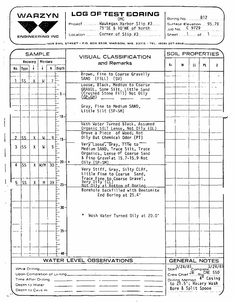
Appendix C - Logs of Test Boring - General NotesUnified Soil Classification System InformationLogs of Test Boring Nos. B7 - B12
Appendix D - Soil Test ResultsDrawing Nos C 9729-A1, A2 and Bl

SEDIMENT AND SHORE SAMPLE COLLECTIONWAUKEGAN HARBOR SLIP #3
WAUKEGAN, ILLINOIS
INTRODUCTION
This report describes soil sampling and testing performed during
March 16 through March 25, 1981 at the Waukegan Harbor Slip #3. Waukegan
Harbor is located in Section 22, T45N, R12E, Lake County, Illinois. Slip
#3 is located at the north end of the Harbor (see Drawing C 9729-B1). The
purpose of the sampling program was to obtain soil samples at specified
depths for polychlorinated biphenyl (PCB) analysis and to test particular
engineering properties of the organic clayey silt (muck). Chain of custody
methods were employed and care was taken to attempt collection of chemically
undisturbed samples as requested by Mason and Hanger - Silas Mason Company,
Inc., (MHSM). The methods used are described later in the text.
CHAIN OF CUSTODY PROCEDURES
Chain of custody procedures were employed with regard to handling
of sediment core samples obtained in the investigation. The following dis-
cussion describes chain of custody procedures employed.
During March 17 through March 20, 1981, seventeen sediment core
samples (ASTM D1586) from Borings B7, B8 and B9 were obtained; and during
March 23 and March 24, 1981, seventeen additional sediment core samples
from Borings BIO, Bll, and B12 were obtained. These samples required
chain of custody procedures. Each sample was placed in a 32 oz. jar, and
each jar boxed. At the end of each work shift and during the lunch break,
the samples were stored under observation or were locked securely. When a
box was filled, it was affixed with a U.S. Environmental Protection Agency
WARZYN
May 26, 1981 -2- C 9729
• \
(U.S.E.P.A.) approved chain of custody seal and stored under secure lock.
At the end of the work week on March 20, 1981, and again on March 25,'
1981, each partially filled box was affixed with a U.S.E.P.A. approved
chain of custody seal. Boxes #1 and #2 were transferred by the field
sampler, Geoffrey F. Prior, of-Warzyn Engineering Inc., and delivered to
Vincent Deneen of Raltech Scientific Services of Madison on March 20,
1981. Boxes #3 and #4 were likewise delivered to Raltech on March 25,
1981. On April 1, 1981, two additional sediment core samples (D10S3A and
B12S4A) were likewise delivered to Raltech. Warzyn Engineering retained
custody of three sediment core samples. These are: B9S2, B11S3, and
B12S3. Each of these was affixed with a U.S.E.P.A. approved chain of
custody seal and stored under secure lock at Warzyn Engineering Inc.f| A summary of sediment core samples obtained and parties accept-
ing final responsibility is as follows:
WARZYN

Hay 26, 1981 -3- C 9729
BORING LOCATION
B7
B8
B9
BIO
Bll
B12
SAMPLES OBTAINED
B7S1B7S2AB7S2BB7S3
.. B7S4B7S5B8S1B8S2AB8S2BB8S3B8S4B9S2B9S3B9S4AB9S4BB9SBB9S6B10S1B10S2B10S3A10S3BB10S4B11S1B11S2B11S3Bll 54B11S5Bll 56B12S1B12S2B12S3B12S4AB12S4BB12S5
PERSON/COMPANYASSUMING CUSTODY
Vincent Deneen/Raltech
Geoffrey F. Prior/WarzynVincent Deneen/ Raltech
Geoffrey F. Prior/WarzynVincent Deneen/Raltech
Geoffrey F.Vincent Deneen/Raltech
WARZYN
May 26, 1981 -4- C 9729
SAMPLE COLLECTION AMD FIELD PROCEDURES
Prior to loading onto the barge, the drill rig (CME 550) and
related drilling equipment were steam cleaned at Falcon Marine t/aukegan,
Illinois to remove oil, grease, and mud. Harbor drilling operations were
accomplished by positioning the drill rig on two joined section barges
(total dimensions approximately 20 feet by 40 feet) which were initially
powered to Slip #3 by a tugboat and later manually moved to boring loca-
tions. Drilling operations were performed off the end of the barge.
Present during d r i l l i n g operations were Warzyn Engineering drillers
and a field geologist. Jeffery L. Bruestle, of ENCOTEC, observed from the
y near shore.I
The following general procedures were employed at each boring
location. The boring location was determined from the drawing enclosed
with Attachment I of the Scope of Work from MHSM. The appropriate dimen-
' sions were measured using a fiberglass tape. Actual boring locations were
adjusted from the plan locations somewhat to accommodate field conditions.
All boring locations are within 10 feet of the plan locations. The barge
was maneuvered into position manually and secured v.'ith ropes and chains.
^ Water depth was measured using a 30 inch diameter piece of sheet metal
which was lowered to the top of the muck. A weighted fiberglass tape was
then lowered to the sheet metal and the water depth read. The water depth
was referenced daily to the Falcon Marine Red Marker (Elevation 583.37
feet). For the land borings near Slip #3, the same general procedures
were employed without the barge. Land boring elevations were obtained
using a conventional surveying instrument and were referenced to an assumed
elevation of 100.00 feet on the top nut of a fire hydrant located approxi-
mately 170 feet northwest then 150 feet southwest of the north corner of
Slip #3. Sec Drawing C 9729-B1 for boring locations.! ••**•<• ***C
May 26, 1981 -5- C 9729
' Muck samples were obtained at Borings B7, B8 and B9. A clam-
shell sampler was employed, and an effort was made to obtain representa-
tive samples of the top, middle, and bottom of the muck unit. The muck
samples were placed in separate five-gallon plastic buckets with water
tight lids and delivered to Warzyn Engineering for physical tests. The
muck was sampled at the location of Borings B7 and B8, and in the vicinity
of Boring B9. At boring location B9, the muck unit was overlain by recently
deposited sand and gravel, thereby precluding muck sampling at this loca-
tion. Apparently, the propeller action of the tug and other boats disturbs
the sediments. Drilling at Boring B9 revealed 9.1 feet of sand and gravel
stratified with muck.
Drilling tools and related apparatus were cleaned with acetone
and placed on clean polyethylene plastic sheeting. A 4-inch diameter cas-
ing was then lowered into the water and allowed to settle under its own
weight into the muck. Based on past practices, a measurement of the amount
of settlement of the casing equals the thickness of the muck.
The sediment inside the casing was then flushed out with harbor
water using conventional rotary drilling procedures. At boring locations
B8 and B9, the wash water and drill cuttings were allowed to pass back into
the harbor at the boring location while the water intake for the pump was
kept at the opposite side of the barge in order to minimize contamination
with recirculated water. At boring locations B7, BIO, Bll and B12, the
wash water and drill cuttings were retained in the wash tub. Recirculated
water was not used. When the wash tub became full of water, it was decanted
into the harbor and the drill cuttings retained for later hazardous waste
disposal.
WAPZYrM

May 26, 1981 -6- C 9729
A sediment sample was then obtained by driving a 2-inch diameter,
acetone rinsed, split-barrel sampler for 18 or 24 inches using a 140 pound
weight falling freely through a distance of 30 inches (ASTM D1586). The
split-barrel samples were opened onto clean polyethylene plastic sheeting
and visually examined. The sediment sample was scrutinized for length of
recovery, zones of oily sediment, and field identification. The recovered
sample was then: 1} Cut into a six-inch section, 2) Placed in an acetone
rinsed 32 oz. jar, 3) Capped with aluminum foil and a screw-on lid, 4)
Assigned a boring and sample number (when more than one sample was obtained
from one split-barrel, letter designations were assigned. An 'A1 designa-
tion indicates a sample from the lower portion of the split-barrel. A 'B1
designation indicates a samples from above the 'A1 portion), depth of
sample, blow counts, date, and time; and 5) Placed into a box which v/as
affixed with a USEPA approved chain of custody label.
The borings were advanced by either drilling the casing downward,
or by driving the casing with a 350 pound weight to the desired sample
depth, and then flushing out the casing as previously mentioned. Sampling
intervals were designated by Mason and Hanger - Silas Mason Co. Inc., and
were adhered to as closely as possible. In a few cases, field conditions
would not permit a sample at the designated depth, in which case the sample
was obtained as close to the designated depth as practically possible.
At the end of each borehole sampling, approximately twenty pounds
of bentonite pellets were used to plug the hole. The casing was then
pulled. Any drill cuttings remaining in the wash tub were then shoveled
into 55 gallon drums for disposal as hazardous waste. The tools, washtub,
deck of the barge and rear of the drill rig were hosed down with harbor
WARZYN

May 26, 1981 -7- C 9729
water between boreholes to remove sediment and to flush the pump and
hoses. The tools, casing, and drill rods were rinsed with acetone
and placed on clean polyethylene sheeting in preparation for the next
boring.
Logs of borings were kept throughout the sampling operation.
Sediment descriptions are based on previous laboratory testing and the
experience of the field geologist. Warzyn Engineering performed no
laboratory testing on the underlying sand and clay sediments. Refer to
Appendix C for boring logs.
ENGINEERING TEST RESULTS AND GENERAL SEDIMENT STRATIGRAPHY
The scope of work did not include testing of sand and clay sedi-
ments by Warzyn Engineering. Three muck samples were tested by Warzyn
Engineering for density, gradation (ASTM D 117-80), hydrometer (ASTM D
422-80), and percent moisture (ASTM D 2216-80). These test results are
summarized in Appendix D." The muck thickness varies from 1.8 feet at B7
to 2.9 feet at B8, with a thickness of stratified, recently deposited
sand, gravel and muck measuring 9.1 feet at B9.
For the land borings, thicknesses of fill varied from 0.5 feet
to approximately 7.5 feet. The fill is typically a gravel roadbed under-
l a i n by a crushed stone fill. An old buried wood seawall was encountered
at plan boring location BIO necessitating relocation of this boring. The
wood seawall trends approximately parallel to and approximately 10 feet
northwest of the present sheet piling seawall.
Beneath the muck or fill unit is predominately a gray, fine to
medium sand (SP-SM), little to trace silt, little to trace fine to coarse
gravel. The upper portion of the sand unit contained thin lenses of black,
WARZYN

May 26, 1981 -o- C 9729
organic silt (OL) and wood (Pt) at Boring B12. The lower portion of the
sand unit contained thin lenses (1" to 2") of coarse sand and fine gravel.
At the bottom of the sand unit, a layer approximately 1" to 2" thick of
very oily, coarse, sandy, fine to medium gravel was typically encountered.
The thickness of the sand unit_varied from 3.1 feet at Boring B9 to 13.7
feet at Boring Bll.
Underlying the sand unit is a gray silty clay, little fine to
coarse sand, little to trace fine to coarse gravel (CL). Each boring
penetrated five feet into this unit. A lense of very dense, gray silt (ML)
was encountered within this unit at Boring B7. An oily appearence was
typically not encountered in the clay unit except for the top one foot at
Boring B7.
CLOSING REMARKS
We trust this report, and the information contained herein, meets
your present needs. If you have any questions or desire further information,
please contact us.
Respectfully submitted,
WARZYN ENGINEERING INC.
Geoffrey F. PriorGeologist
GFP/DRV/cgj/dkp[WEI-7-2]
Daniel R. Viste, CPGSProject Manager
WARZYN

APPENDIX "A"
Subsurface Investigation
GENERAL REMARKS
We have endeavored to evaluate subsurface conditions and physicalproperties of the subsoil as revealed by the borings and laboratory testing.A problem inherent in this evaluation is the variability in engineeringproperties within soil strata involved, and specifically in any locationvariation in the soil which is located between borings. Due to natural orman-made causes, subsurface conditions may change with time.
Conclusions drawn and recommendations given in this report arefor a specific proposed use of this site. They are our opinions and arebased upon conditions that existed at the boring locations and such para-meters as proposed site usage, soil loading, elevations, etc.
Since subsurface conditions depend on seasonal moisture varia-tions, frost action, construction methods, and the inherent natural varia-tions, careful observations must be made during construction. These shouldbe brought to our attention as it may be necessary to modify the conclusionsand recommendations presented herein.

APPENDIX "B"
FIELD METHODSfor
EXPLORATION AND SAMPLING SOILS
A. Boring Procedures Between Samples
The bore hole is extended downward, between samples, by a contin-uous flight auger, driven and washed-out casing, or rotary boring withdrilling mud or water.
B. Standard Penetration Test and Split-Barrel Sampling of Soils(ASTM* Designation: D 1586)
This method consists of driving a 2" outside diameter split barrelsampler using a 140 pound weight falling freely through a distance of 30inches. The sampler is first seated 6" into the material to be sampled andthen driven 12". The number of blows required to drive the sampler thefinal 12" is recorded on the log of borings and known as the StandardPenetration Resistance. Recovered samples are first classified as to tex-ture by the driller. Later, in the laboratory the driller's classificationis reviewed by a soils engineer who examines each sample.
C. Thin-walled Tube Sampling of Soils (ASTM* Designation: D 1587)
This method consists of forcing a 2" or 3" outside diameter thinwall tube by hydraulic or other means into soils, usually cohesive types.Relatively undisturbed samples are recovered.
D. Soil Investigation and Sampling by Auger Borings(ASTM* Designation: D 1452)
This method consists of augering a hole and removing representa-tive soil samples from the auger flight or bucket at 5'0" intervals orwith each change in the substrata. Relatively disturbed samples areobtained and its use is therefore limited to situations where it is satis-factory to determine approximate subsurface profile.
E. Diamond Core Drilling for Site Investigation(ASTM* Designation: D 2113)
This method consists of advancing a hole in hard strata by rotatingdownward a single tube or double tube core barrel equipped with a cuttingbit. Diamond, tungsten carbide, or other cutting agents may be used forthe bit. Wash water is used to remove the cuttings. Normally a 2" O.D. by1 3/8" I.D. coring bit is used unless otherwise noted. The rock or hardmaterial recovered within the core barrel is examined in the field andlaboratory. Cores are stored in partitioned boxes and the length of re-covered material is expressed as a percentage of the actual distance pene-trated.
*American Society for Testing and Materials, Philadelphia, Pennsylvania

APPENDIX C
LOG OF TEST BORING - GENERAL NOTES
UNIFIED SOIL CLASSIFICATION SYSTEM INFORMATION
LOGS OF TEST BORING NOS. B7 - B12
WAPZYN

LOG OF TEST BORING
General Notes
Descriptive Soil Classification
GRAIN SIZE TERMINOLOGYSoil Friction Pirticle Sin U.S. Standard Sieve Size
Boulders . . . . . . . . . . . . . . . . . larger than 12" . . . . . . . . . . . . . . . . . larger than 12"Cobbles . . . . . . . . . . . . . . . . . . 3' to 12" ...... . . . . . . . . . . . . . . . 3 " to 12"Gravel: Coarse . . . . . . . . . . . . . }»" to 3" . . . . . . . . . . . . . . . . . . . . . 3< to 3"
Fine . . . . . . . . . . . . . . 4 76 mm to ^'4 ' . . . . . . . . . . . . . . . *4 to 3«"Sand: Coarse .............. 2.00 mm to 4.76 mm . . . . . . ... '10 to -4
Medium . . . . . . . . . . . . . 0 42 mm to 2 00 m m . . . . . . . . . . . -40 to -10Fine . . . . . . . . . . . . . . . . 0 074 mm to 0 42 mm . . . . . . . . . -200 to «40
Silt . . . . . . . . . . . . . . . . . . . . 0 005 mm to 0 074 mm .. . . . . . Smaller than -200Clay . . . . . . . . . . . . . . . . . . . . . Smaller lhan 0 005 mm . . ... Smaller than «200
Plasticity characteristics differentiate between silt and clay
GENERAL TERMINOLOGYPhysical Characteristics
Color, moisture, grain shape, fineness, etcMa/ar Constituinis
Clay. sill, sand, gravelStructure
laminated, varved. f ibrous, strat i f ied.cemented, fissured, etc
Geologic OriginGlacial, alluvial.eolian. residual, etc
RELATIVE PROPORTIONSOF COHESIONLESS SOILS
Proportional Defining Range ByTerm Percentage of WeightTraci . . . . . . . . . . . . . . . . . . . . . . . 0%. 5%Little . . . . . . . . . . . . . . . . . . . . . . . 5%-12%Some . . . . . . . . . . . . . . . . . . . . . . . 12v3S9bAnd . . . . . . . . . . . . . . . . . . . . . . . . 35%-50X
ORGANIC CONTENT BYCOMBUSTION METHOD
Soil Description Loss on Ignition
Non Organic . . . . . . . . . . . . . . . less than 4%Organic Silt/Clay . . . . . . . . . . . . . . . . 4-12XSedimentary Peat . . . . . . . . . . . . . . . 12-50XFibrous and Woody Peat .... More than 50%
RELATIVE DENSITYTermVery LooselooseMedium DenseDense .Very Dense .
"N" Value
. . 04. . . . . 4-10
. 10 30. . . . 30 50
Over 50
CONSISTENCYTermVery SoftSoftMedium .Stiff ....Very StiffHard ...
q.-tons/sq. ft.
... 00 to 0.25.. 0 25 to 0.50
... O.SOto 1.0. . . 1 . 0 t o 2 0. .20 to 40. . . . . . Over 4 .0
PLASTICITYTerm Plastic IndeiNone to Slight . . . . . . . . . . . 0-4Slight ................. 5-7Medium ................ 8-22High to Very High ..... Over 22
The penetration resistance, N. is the summation of the number of blows required to effect twosuccessive 6" pentrationi of Ihe 2" split-barrel sampler. The simpler is driven with a 140 Ib weightfalling 30" ind is seated to a depth of 6" before commtncing the standard penitration tut
Symbols
DRILLING AND SAMPLINGCS—Continuous SamplingRC-Rock Coring: Size AW, BW, NW, 2' W
RQD-flock Quality DesignatorRB-fiock BitFT-Fish TailDC-Drove Casing
C-Casing: S:it 2W, NW, 4', HWCW-Clear WaterOM-Drilling Mud
HSA-Hollow Stem AugerFA- Flight AugerHA-Hand Auger
COA-Clean-Out AugerSS-2 Diameter Split-Barrel Samplt
2ST-2 Diameter Thin-Wal led Tube Sample3ST-3 Diameter Thin Walled Tube SamplePT-3 Diameter Piston Tube SampleAS-Auger Sample
WS-Wash SamplePTS- Peal Sample
PS-PiUher SampleNR-No Recovery
S — SoundingPMT Borehole Pressuremeter Test
VS-Vane Shear TestWPT-Water Pressure Test
LABORATORY TESTSg.—Penetrometer Reading, tons/sq ft .q.—Unconlmed Strength, tons/sq ft.W-Moisture Content, S*U-LiQuid limit. %PL-Plastic Limit. SSL-Shrinlage Limit. \II—Loss on Ignition, %D-Dry Unit Weight. Ibs /cu. ft.
pH- Measure of Soil Alkalinity or AcidityFS-Free Swell. %
WATER LEVELMEASUREMENT
" — Water Level at time shownNW-No Water EncounteredWD-While DrillingBCR—Before Casing RemovalACR-After Casing RemovalCW-Caved and WetCM—Caved and hioist
Note. Watir level meaturements shown onthe boring logs represent conditions at thetime indicated and may not reflect staticlevels, especially in cohesive soils.
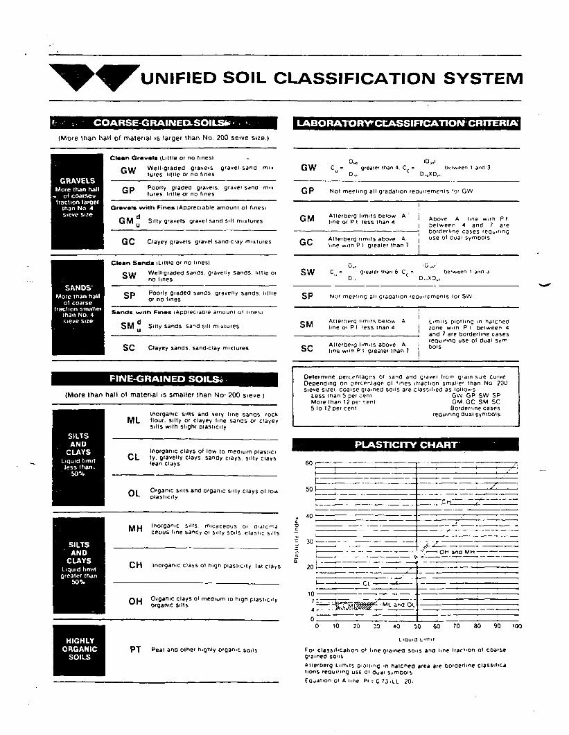
UNIFIED SOIL CLASSIFICATION SYSTEM
COARSE-GRAINEDuSOILSfc(More than half of material is larger than No 200 seive size I
Clean Gravels (Little O'no linesiGW Well graded gravels gravel sand mi«
lures, little or no linesGRAVELS
More lhan hall- ol coarse*
fraction largerthan No 4sieve size
Gravele with Fines (Appreciable amount ol lines)
GM Silly gravels gravel sand silt mm lures
GC Clayey gravels gravel sand clay mixtures
Clean Sands (Little or no ImeslWell graded sands, gravelly sands, hitie orno lines
CD Poorly graded sands gravelly sands l i t t le^ or no lines
Sands with Fines (Appreciao'e amount ot Imes}
SM Silly sands, sand sill mixtures
SC Clayey sands sand-clay mixtures
FINE-GRAINED SOILS*
(More than half of material is smaller than No-200 sieve)
Inorganic sills and very line sands rockML Hour, silly or clayey line sands or clayey
sills with slight plasticity
SANDSMore than hall
ol coarsefraction smailei
than No. 4
SILTSAND
CLAYSLiquid limitless than.
50%
SILTSAND
CLAYSLiquid limitgreater than
50%
Inorganic clays of low to medium plasnciCL ly. gravelly clays, sandy clays, silly clays
lean clays
Organic silts and organic silly clays ol lowplasticity
• •11 Inorganic si l ts, micaceous O' rjiaicmamn ceous line sandy o'si l ly sons elastic si l ts
CH Inorganic clays ol high p last ic i ty lat clays
LABORATORVCCASSIFICATION CRITERIA
C = greater than 4 C = between t and'3u D.,, D.0XD..
GP No, meeting ,„ gradation requirements 'or GW
Between 4 and 7 areborderline cases requiring
Alterberg limits above A | use ol dual Symbolsline with PI greater than 7
C i gieaier man 6 C - tie'ween 1 inn J" D.. D.»XO.r
SP Not meeting all gradation requirements lor SW
SM At terDerq limits be'ow Aline or P I 'ess than 4
Alterberg limns above Aline with P I greater than 7
Limits plotting m hatcheszone with P I between 4and 7 are borderline casesrequiring use ol dual syrrtbois
Determine percentages 01 sand and gravel Irom gram size curveDepending on percentage ol 'mes i t ract ion sma»e' lhan No ?00sieve sizei. coaise grained soils are classif ied as lonov.s
Less lhan 5 pef cent GW GP SW SPMore lhan 12 pe- cent GM GC SM SCbio 12 pet cent Borderline cases
requiring dual symbols
PLASTICITY CHART
60 r
501
40 •
• OH and MM-
Cl
OH Organic clays ol medium 10 high plasticity 7- ——— 'OH organic silts ~~
0
M{- ang °L
10 20 30 <0 60 70 80 90 '00
HIGHLYORGANIC
SOILSPT peal and other highly organic soils
LiQuid frriT
fo< classification ot Imegramea soils and lme traction ol coarsegramed sonsAtte'berg Limits pioitmg m natcnea area are bo'derlme classil>calions requiring use ol duai s?moo'SEquation ol A line Pi = C '3 iLL ?0.

WARZYN LOG OF TEST BORINGOMC
Project ..^M^egan Harbor Slip f3..." '... ' .. 8 0 ' S E . . & ^ 7 " , 5 . \ S w ' p f ' " ' "
Location .... ... Corner, o.f.. Slip. j¥3.
Boring No. ....... B7
Surface Elevation ...Job NO. .... C.. 9729
'
SheetENGINEERING INC
.________________14O9 EMIL STREET • P.O. BOX 9538. MADISON. WIS. 53715 • TEL. (6O8) 257-48-18.
f SAMPLERecovery
No.
1
?
345
-
Type
SS
SSSSSSSS
\
— •
-._.
X
XXXX
Moisture
\
W
MMMM
N
43
372183
110
Depth
5
— 10-
—
r15~
^-20-
—tt-
'-3Q-
'-25-
^-40-
VISUAL CLASSIFICATIONand Remarks
WATER to 10.4'
Black MUCK (OL)
Dense, Gray, Fine to MediumSAND, Some Silt Trace Fineto Coarse Gravel (SP-SM)Very Oily at 18-18.5'
Very Stiff, Gray, SiltyCLAY", Little Fine to CoarseSand, Trace Fine to CoarseGravel (CL) Oily to 19.5'Very Dense, Gray SILT, LittleFine Sand (ML) Not OilvBorehole Backfi l led with Bentonite
End Boring at 24.5 '
-
WATER LEVEL OBSERVATIONSWhile Dnllinc
Upon Comp
Time Af ter C
Depth to WaL Depth to Ca^^
)etionDnllin
ter
ve In
of Drilling
a
SOIL PROPERTIES^
Qu w LL PL
1
D
———
GENERAL NOTESStar3/16/81completeV16/81
Crew Chief ..OR Fj^ig CME .550Dnlling Method .n^....20. 5?; Rotary Wash Bore& Sptit Spoon
s
T

WARZYPJ LOG OF TEST BORINGore
Project .........Waukegan..Harbor..Slip..#3............ ... 122VSE..& .5'SW..of..North............
Location .... Corner..of..Slip..#3......................
Boring No. ..... ...
Surface Elevation .578.92Job NO. .......C..972.9...Sheet 1
ENGINEERING INC
_________________14O9 EMIL STREET • P.O. BOX 9538, MADISON, WIS. 53715 • TEL. (6O8) 257-4848.
. . . . Of1
/^ SAMPLERecovery
No.
—— --
1
2
3
4
Type
SS
SS
SS
SS
It
— -\
— --
XX
X
X
11
MoisturelT
__w_W/M
M
M
N Depth
fr
19
39
29
85
— j —
10
-15-
-20-
?"iL*l
——
•»nou
^35-
^-40
VISUAL CLASSIFICATIONand Remarks
UATFR tn ID Q1nrt 1 ui\ I.O 1 U . j
Very Loose, Black MUCK (OL)
Medium Dense, Gray Fine toCoarse SAND, Little Silt,Little Fine to Coarse GravelSlightly Oily (SW-SM)
Very Stiff, Gray Silty CLAY,Little Fine to Coarse Sand,Trace Fine to Coarse GravelNot Oily (CL)
Not Oily at Bottom of BoringBorehole Backfi l led with Bentonite
End Boring at 27.5 '
WATER LEVEL OBSERVATIONS
While Drilhnc
Upon Comp
Time Af ter 1
Depth to W;L Depth to Ca
•V ' X^
3etior
Drill.n
ster
ve In
) of Drilhnc
g . _ .. .
SOIL PROPERTIES^
qu
——
w
- - - - -
LL
---
PL
-
D
-----
•«•
-
GENERAL NOTES
StarS/ 1 9/81Complete3/l 9/81Crew Chief ..JR Rig CME 550Drilling Method ^" Casingto 21.5' ; Rotary WashBore i Split Spoon """........... . . . . . . . . . . ....... J

WARZYN LOB OF TEST BORINGCMC
Project .............Waukegan..Harbor..SIi.P...f.3.. ...... ........ . . .105'SE..&. 59.'.SW of North.......
Location .... ... .Corner.. .9.f..S).1 .P.M.................ENGINEERING INC
._________________14O9 EMIL STREET • P.O. BOX 953B, MADISON, WIS. S3715 • TEL. (6O8) 257-4848
B9Boring No. . . . . . . . . . . . . . . . . .. .. .
Surface Elevation 578.92Job No. .......C...9729............
Sheet ...V.... of . . . . . ' . . . . . .
f SAMPLERecovery
No.
1
2
3
4
56
"
Type
SS
SS
SS
SS
SS.
SS
.!
0
x
Ji.X
X
X
Mois
1
w
wM
MM
i
ure
N
0
1
7
79
80
63
——
Depth
c.«J
" 10
^-15-
-20-
—75
^-30-
I
-35-
At\
VISUAL CLASSIFICATIONand Remarks
WATER to 5.7'
*Very Loose, Gray & BlackFine to Medium SAND, SomeSilt, Some Organics (StratifiedMuck & Sand) Not Oily (SP-SM/OL)Split Spoon Settled from 6.1-9.1'
Under Weight of Hammer-No Blows
Loose, Gray Fine to MediumSAND, SomeSilt, Not Oily(SM)
Very Stiff, Gray Silty CLAY,LittTe Fine to Coarse Sand,Little Fine to Coarse GravelNot Oily (CL)4" Lense of Fine to Coarse Sandat. 19.8-70.1 'Not Oily At Bottom of BoringBorehole Backfi l led with Bentonite
End Boring at 24.5'
* Black, Fine to Coarse SAND,Little Fine to Coarse Gravel,Little Silt (SW-SM)
WATER LEVEL OBSERVATIONS
While Drilling
Upon Co<"npl
Time Af ter C
Depth to Wa. Deoth to C*
etion
JriMin
ter
JO lO
of Drilling
a
SOIL PROPERTIES^
qu W LL PL
1
D
_......_
GENERAL NOTESstar£/18/81Complet(3/18/81Crew Chief JR.. RiJCME.550_
Drilling Method 4" Casingto 20.5' ; Rotary WashBore & Split Spoon "

WARZYN LOG OP TEST BORINGOMC
Project Waukegan Harbor Slip f335'SE & 7.5 'NE of 'North
Location .... . ..c.P.rner of Si i p #3ENGINEERING INC
-___________14O9 EMIL STREET • P.O. BOX 9538. MADISON, WIS. 53715 • TEL. (6OB) 257-4848
Boring No. . ... .BIO
Surface Elevation ....95.68Job No. ..C..97.29 ..............Sheet .1... of
f SAMPLERecovery
No.
1
2
3
4
Type
SS
- • -
SS
SS
SS
1X
_x_
X
X
Mois1
w
w
d/M
M
lure
N
16
2
37
63
Depth
— 5-
~ 10
r15-
" 20
—
^25-
—
^30-
-35-
^40-
VISUAL CLASSIFICATIONand Remarks
*Medium Dense, Black, Medium toCoarse GRAVEL, Some Sand, LittleSilt (FILL-Crushed Stone) NotOily (GP-GM)
Very Loose, Gray, Fine to MediumSAND, Little Silt, Little Fineto Coarse Gravel, Not Oily,Lense of Coarse Sand & FineGravel at 12.8' to 13.0' (SP-SM)
Wash Water Turned Oily at 19.5'
Very Stiff, Gray, Silty CLAY,Little Fine to Coarse Sand,Little Fine to Coarse Gravel,Not Oily (CL)Not Oily at Bottom of BoringBorehole Backfi l led with Bentonite
End Boring at 25.9'
* Brown Fine to Coarse SandyGRAVEL, Some Silt (Roadbed)(SW-SM)
WATER LEVEL OBSERVATIONSWhile Drilling
Upon Completion
Time After Drillin
Depth to Water, Depth to Cave in"\^
of Drilling
a
SOIL PROPERTIES^
qu W IL PL D
>.
-
GENERAL NOTES
Start3/24/8borr
Crew Chief .J.R . . IF
Drilling Methodto 21.5 ' ; RotBore & Split
piete/24/81,igCME 550^Casing"ary Wash..Spoon

WARZYN
ENGINEERING INC
LOG OF TEST BORINGOMC
Project Waukegan Harbor Slip #3....'"".'.'".'".'.'65.VSE . & ^ 3 V N E " o ' ' ' '
Location . . . . . . .Corner:..of .Slip:
Boring No. .....^l V
Surface Elevation 95.87Job NO. ...P. 9729Sheet . . . . Of .
1<JO9 EMIL STREET • P.O. BOX 9538, MADISON. WlS. 53715 • TEL. (6O8) 257-48.48.
f SAMPLERecovery
Ho.
1
2
3
4
5
6
r
—
Type
SS
SS
SS
SS
SS
SS
J
— X
X
X
X
X
X
- -
Mois
1
_W-
w
w
w
M
M
1
ure
N
-J-
25
13
11
61
59
Depth
r5~
~ 10
r15~
" 20-
—
1C
I-30-
r35~
1-40-
VISUAL CLASSIFICATIONand Remarks
*
Loose, B lack, Fine to CoarseSAND, Little Silt, Trace Fineto Coarse Gravel, Not Oily (SP)
Medium Dense, Gray, Fine toCoarse SAND, Little Silt,Trace Fine to Medium Gravel,Trace Organics, Not Oily, Lenseof Black Organic Silt at14. 9-15. T (SP)Wash Water Turned Oily @ 16.0-18.0'Lenses of Coarse Sand & Fine Gravel0 16. 5-16. 6', 19.4-19.6' &20.1-20.3', Not Oily
Very btitf, Gray, bitty LLAY,Little Fine to Coarse Sand,Little Fine to Coarse GravelNot Oily (CUNot Oily at Bottom of BoringBorehole Backfilled with Bentonite
End Boring at 26.4'
* Brown, Fine to Coarse SandyGRAVEL, Some Silt (FILL)(GW-GM)
WATER LEVEL OBSERVATIONSWhile Drilling
Upon Completion
Time After Drrllin
Depth to Wateri Depth to Cave in
"X^
Of Drilling
a
SOIL PROPERTIES^
q« W LL PL
- - - •
- — -
I
1ti
D
GENERAL NOTESStaiV23/81.comp.ete3/23/8-
Crew Chief ...JR RigCME 550.
Drilling Method 4" Casin9to 22.5 ' ; Rotary WashBore & Split Spoon
./
WARZYN LOG OF TEST BORINGOMC
Project ............Waukegan..Harbor.Slip..#.3....... . . . . . . . . . . . . 75 'SE &JP.'.NE. of..North........
Location ...........C.orner..o.f.Slip.J.3..................ENGINEERING INC
..________________14O9 EMIL STREET • P.O. BOX 9538. MADISON, WIS. 53715 • TEL. (6O8) 257-4848
Boring No. . . . . . . . . . . . .
Surface Elevation . .95. 79 .Job No. ...fr..?.:.?.9..'...............Sheet . ..1...... of . .1.
( SAMPLERecovery
No.
1
2
3
4
5--'
Type
SS
ssSS
SS
SS
\
X
X
X
X
X
Mois
\
W
W
w
W/M
M
lure
N Depth
-T-7
9
5
30
39
-
5
10
r15"
" ?n
—
1C— 25-
—
•»n
r35~
-40-
VISUAL CLASSIFICATIONand Remarks
Brown, Fine to Coarse GravellySAND (FILL) (SW)Loose, Black, Medium to CoarseGRAVEL, Some Silt, Little Sand(Crushed Stone Fill) Not Oily(GP-GM)
Gray, Fine to Medium SAND,Little Silt (SP-SM)
Wash Water Turned Black, AssumedOrganic SILT Lense, Not Oi ly (OL)Drove a Piece of Wood; NotOily But Chemical Odor (PT)Very Loose, Gray, Fine toMedium SAND, Trace Silt, TraceOrganics, Lense of Coarse Sand& Fine Gravel at 15.7-15.9 Not
* Oily- (SP-SM)Very Stiff, Gray, Silty CLAY,Little Fine to Coarse Sand,Trace Fine.tovCoarse Gravel,Very Oily (CL)Not Oily at Bottom nf RnringBorehole Backf i l led with Bentonite
End Boring at 25.4'
* Wash Water Turned Oily at 20.0'
WATER LEVEL OBSERVATIONS
While Drillinc
UDOn Comp
Time After CDepth to Wa
. Depth to Ca,,\̂
3 . . . .
etior
Dnllin
ter
ve In
of Drilling
a
SOIL PROPERTIES^
qu
— —
w LL PL
1
0
-
——— >
GENERAL NOTES3/24/8
Start
Crew ChiefDrilling Metto 21.5'Bore & S
CorrJR F
hod; Roi.slit
3iplete,. CME''94" C«ary 1Spoo
/24/81550'
jsingtashn..................... ......... j

ENGINEERING TEST RESULTS OF MUCK SAMPLESWAUKEGAN HARBOR SLIP #3
MARCH, 1981
Muck Sample
Wet Density(PCF)
Dry Density(PCF)
% Moisture Wry^at 105°C
% Moisture(<4/tvfc.
B7
68.79
29.13
^ 136.11
•i,) 134.25
B8
66.84
26.88
148.64
146.64
pa itstJM
68.91 lh tt*rty 'ft* ' ''*&
48.69 ^££ ^'S^A^-f1 • : /CO
41 53 tffci*^ > ,,.-HI. jo >y • , , \ f.{/*<f* £ei:K
40.89 4f_fc*<6-. y r
L
GFP/cgj/dkp[WEI-7-2]

APPENDIX D
SOIL TEST RESULTS
DRAWING NOS. C 9729-A1, A2 and Bl
WARZYM• »*Ol»*f •••**<) i*«C

c
•o
"D
Z
o0
.0E 0z3 S. i
? s•o
J swi O
or*
0
0
OD
«r
«%
~C
O
' \VI
Percent Coarser by Weight
o o o o o ° ° o o §
-
• ^ c
—
b•-
] M1
16
0
i
x-(;
Jfy
> °
v*
/^
• /
*~*
.r* -̂
— **^
.
<Q
4-Xj , /
—— 1 /* — '
^
<
/
iTv'r
Y
ks
o o o o o o
Percent Finer by Weight
^
/
cr
/y
jQ
>«
\A/ARZYN
OWN Jg>pJ'T7/l<5? J CHK'D (jfcf JAPP'D*
//
(i
fnc?n33
"7\
_
0
000
i6
0o
0o
o «A
i!tiE
Ica>N
o.E
6
0
oIA
(J
i
II
1 aN
rs|
WO
IQ3W
P
13AV
KO
3NIJ
13AY
»O3S
IYO
D
Uni
fied
Cla
ssifi
catio
n Sy
stem
(A
STM
024
87)
c0
"5
0
U
.i/t
"OC
0
CL
^
z
.£
aQ
'at
3U
v-VJ
\JJ
CT
1-7
^O
cD\T>
&vn
v:o
«
_\
tCcr
V-
!A
1
•z
oD
*
S
-
o3
(O
O
I-\
o
GRAIN SIZE ANALYSIS
SEDIMENT & SHORE SAMPLE COLLECTIONWAUKEGAN HARBOR SLIP #3
WAUKEGAN, ILLINOIS
T) l^ «t^ ^ _ 1 DATE *Z/?i /Ri 1 ̂ <~*-tir* A •

o
o
XI
0
iE 02 S«* s>*
-D 0
•oS o
V)
vi 0
O
O
oto
* -»*Ji **c
c
f -<i"•)»j; -
TJ
i 5• -Aifo3
Percent Coarser by Weighl
o o o o o ^ o o o Q^ C 4 O ^ y ^ - O f s • • ^ ^ -
- 1
-/
^3
-
• -— -
i *1 "̂ 1
r/
^
,̂̂ -
————
.—— *-
-
^>
-
^7)--^
zr ^X
<
J
J
-e4=
i ,
ap
(j
-
o
?p
—
SO
10
5 1
05
01
005
001
OO
OS
0 00
1G
rain
Siz
e in
Mill
imet
ers
u
«
2 Z
ME
DIU
MS
AN
DC:O
ARSE
SA
ND
l\u. atO
(•O UJ
52uO
Uni
fied
Cla
ssifi
catio
n S
yste
m (
AS
TM D
2487
)
cO
1C
U
u#fc
#•oe
#
6
a.
2
X2
Va
*aE
u
^F-
^
t-
*vJ
r\ i
VJ
£a
1V— '
A
V
•
0
P O o O O O O O
Percent Finer by Weight WAPZYM
OWN J&PjfAVi? | CHKD 4fp J APP-D^JL*^
GRAIN SIZE ANALYSIS
SEDIMENT & SHORE SAMPLE COLLECTIONWAUKEGAN HARBOR SLIP #3
WAUKEGAN, ILLINOIS
*V *^— J DATE ^te/Kt \ ̂ 9729 - A2.
