warranty card surechlor 3000 salt water chlorinator ... · water above the temperature of 45°c has...
TRANSCRIPT

Warranty Card
Poolrite Equipment Pty. Ltd. Poolrite Equipment Pty. Ltd.415 Creek Road, 6 Forsyth Close,P.O. Box 520, P.O. Box 7055,Mt. Gravatt. QLD. 4122 Australia Wetherill Park. N.S.W. 2164 AustraliaTelephone: (07) 3323 6555 Telephone: (02) 9729 0166Facsimile: (07) 3323 6500 Facsimile: (02) 9729 2759
Poolrite Equipment Pty. Ltd. Poolrite Equipment Pty. Ltd.15 Yiannis Court, Unit 10/16 Ledgar Road,Springvale. VIC. 3171 Australia Balcatta. W.A. 6021 AustraliaTelephone: (03) 9547 4188 Telephone: (08) 9344 3871Facsimile: (03) 9547 1023 Facsimile: (08) 9345 3923
Poolrite Equipment Pty. Ltd. Poolrite Equipment Pty. Ltd.36 Hugh Ryan Street, Unit 22, 761 Great South Road,Garbutt. QLD. 4814 Australia Penrose. AucklandTelephone (07) 4779 4880 New Zealand.Facsimile (07) 4779 6714 Telephone: (09) 571 0210
Facsimile: 0800 766 574 owne
rsm
anu
al
SURECHLOR 3000Salt Water Chlorinator
Models: NSC160S/TS/TSDLNSC210S/TS/TSDLNSC310S/TS/TSDLNSC620S/TSAKS150S/TS/TSDLAKS250S/TS/TSDLAKS350S/TS/TSDLAKS700S/TS
Item No. 22536
Stella Print
WARRANTY CARD
Surechlor 3000 Salt Water Chlorinator
Poolrite Equipment Pty. Ltd.
Your Poolrite Surechlor 3000 is manufactured to the highest possible standards andmost up-to-date technology.
Accordingly the equipment carries the following Warranty, should a fault occur due tofaulty manufacture or materials.
Important
In the event of a fault covered by Warranty occurring, the Purchaser must, in the firstinstance, contact Poolrite Equipment Pty. Ltd. or the closest authorised PoolriteDistributor. Poolrite Warrant the original purchaser of the Power Pak and ElectrolyticCell for a period of 24 months from the Date of Purchase by the original Owner, shouldexamination disclose to it’s satisfaction that the Cell or Power Pak has failed due tofaulty manufacture or materials. In addition for a further period of 36 months theElectrolytic Cell will be repaired or replaced at Pro Rata cost from Date of purchase bythe original Owner.
The Warranty is void if the following occur:
1. Damage resulting from matters beyond Poolrite’s control.
2. The Cell or Power Pak has been installed incorrectly and not in accordance withthese instructions.
3. The Power Pak has been connected to a power supply other than 240 volt 50 Hz.
4. The Cell or Power Pak has been used for any purpose other than swimming poolor spa sterilisation.
5. Water above the temperature of 45°C has been permitted to flow through the Cell.
6. Water has not been permitted to flow freely through the Cell when turned on.
7. The safety flow detector or connections have been tampered with.
8. The Power Pak has been serviced by a person other than a person authorised todo so by Poolrite or it’s agent.
9. The Cell power terminals have been submersed in acid solution when cleaning.
10. Non-swimming pool grade salt has been used in the pool.
This Warranty is applicable to workmanship and materials. Poolrite will repair or replaceat no charge, all parts returned freight paid, which display faulty workmanship ormaterials.
Poolrite Equipment Pty. Ltd. accepts no responsibility for loss, damage or injury toperson or property arising from Warranty failure of equipment, or installation of thatequipment. Unless with the express prior authority of Poolrite, any repair or replacementshall be provided only by Poolrite or it’s authorised distributors and this Warranty shallnot extend to any expenditure otherwise incurred.
Warranty Card
Name of Purchaser
Address
Purchased From
Date
Equipment and Model
IMPORTANT: This card must be filled in andreturned to Poolrite Equipment Pty. Limitedwithin 14 days of purchase to render theWarranty effective.
Queensland Head OfficeSales & Export Brisbane415 Creek Road,P.O. Box 520,Mt. Gravatt. QLD 4122Telephone: (07) 3323 6555Facsimile: (07) 3323 6500
Poolrite Equipment Pty. Ltd.Unit 22, 761 Great South Road,Penrose. AucklandNew Zealand.Telephone: (09) 571 0210Facsimile: 0800 766 574

INDEX
INSTALLATION INSTRUCTIONS 1Surechlor 3000 Cell 1
Surechlor 3000 Power Pak 2Connecting The Pool Pump 3Underwater Pool Light Models 3Off-Peak Installations 4
Adding Salt To The Pool 5Marble Plaster Surface Pools 5Calculating Pool Capacity 5Calculating Salt To Be Added 6Salt Calculation Chart 7Adding Salt and Stabiliser 7Dissolving The Salt 8When The Salt Has Dissolved 8
SETTING AND CONTROLS 9POWER PAK OPERATION 9
Power/Status Indicator — All Models 9Chlorine Control — All Models 9Led Salt Monitor — All Models 10Models Coded NSC/AKS.-S 10Models Coded NSC/AKS.-S 11Automatic Time Switch 11Setting The Time Switch 11Synchronising The Time Switch 11Automatic Operation Switch Setting 12
Underwater Pool Light Models 12HOW YOUR SURECHLOR 3000 WORKS 13MAINTENANCE OF POOL CHEMISTRY 14
Chlorine Level 14pH Control 14Adding Acid 15Total Alkalinity 15Cyanuric Acid Stabiliser 15Calcium Hardness 15
Maintaining Salt Levels 16MAINTENANCE OF YOUR SURECHLOR 16 & 17
Cell Cleaning 17Overload Protection 18How Long Should Your Cell Last 18Common Causes of Cell Failure 19Customer Responsibilities 19Operational Check List 20
ELECTRICAL SPECIFICATIONS 21WARRANTY

INSTALLATION INSTRUCTIONS
OWNERS MANUAL
Please hand this Owner’s Manual to the pool owner after installationis completed as it contains the Warranty Card and vital informationfor correctly maintaining the pool and this product!
SURECHLORCELL
Ideally, the electrolyticcell should be installedin a position with 1.5metres of a vertical wallor fence to allow thePower Pak to be easilymounted without theneed to provide anadditional post.
The cell must beinstalled horizontally(level) within 5°, in thereturn to pool line, withthe two plumbing portsand arrow on labelpointing down.
The water can flow ineither direction throughthe cell.
Heaters and otherequipment in the returnto pool line must bebefore the cell i.e.between the cell andfilter.
1

2
If an air blower is fitted to an air inlet for venturi jets, precautionsmust be taken to prevent gases generated in the Surechlor cell fromaccumulating in the blower and associated pipework.
The recommended way of achieving this is to install an inverted loopin the air line with a 3mm (max.) diameter hole in the top venting toatmosphere.
The diagram below shows the general arrangement for this loop.
Vented Loop
Warning: The Warranty will be void if the cell is not installed exactlyas specified.
SURECHLOR POWER PAKThe Power Pak Enclosure is approved and rated to Degree OfProtection IP24 and therefore can legally be installed in the PoolZone as defined in the AS/NZS 3000 - 2000 Wiring Rules. It mustbe mounted on a vertical wall or fence within 1.5 metres of the celland at least 1 metre above the ground. Also, it must be in a positionto allow its supply lead to be plugged into a 10 amp 240 volt powerpoint.
Remember the filter pump must be plugged into this Power Pak.
Start by selecting a suitable place to attach the Mounting Bracketusing the two screws provided. The Mounting Bracket must be fixedwith the screws horizontal and the vent louvres above the screwsfacing upwards.
If no suitable wall is available, then install a 100mm x 100mmhardwood post with a vertical mounting board 400mm wide x 300mmhigh x 18mm thick attached.

Hook the Power Pak onto the Mounting Bracket by the top edge atthe rear of the box. When secure, plug the power lead into a suitable240 volt power point but do not switch on.
CONNECTING THE POOL PUMP● Raise the clear Control Panel Cover on the front of the Power Pak
and loosen the two retaining screws in the bottom right handcorner and remove the Cable Entry Cover by pulling downwards.
● Plug the pool pump into the pump socket on the front panel(see Note: on page 4 about the use of large or 3 phase pumps).
● SURECHLOR MODELS NSC/AKS....TS-DL are provided with aseparate, dedicated power supply to operate a 12v 100 wattunderwater pool light. This is controlled by a rocker switch andprotected by a 10A type 3AG fuse labelled POOL LIGHT locatedat the bottom of the control panel. If this model Surechlor is beinginstalled and a 12 volt pool light is installed, its cable should nowbe connected into the special B.P. Connectors provided.
● Refit the Cable Entry Cover making sure all cables pass throughthe tunnel behind it to ensure they do not interfere with the properclosing of the Control Panel Cover.
● Tighten retaining screws.
3

Off-Peak Installations
When connection to off-peak tariff is being considered, we suggestthat you contact your Poolrite State Office for advice prior toinstallation.
Warning: The Warranty will be void if the Power Pak is installed oroperated .....
a) on, or less than 1 metre from the ground.
b) in a position where flooding from ground water could occur.
c) where the airflow is obstructed, i.e. within an unvented auxiliaryenclosure.
d) with the weatherproof Control Panel Cover permanently open or removed if installed outdoors.
e) with a load (pump) connected to the 240 volt pump outlet socketgreater than 1.5kw (continuous).
f) from an electrical supply socket which is not rated to supply10 amps at 240 volts 50Hz and is not adequately protected bythe correct size fuse or circuit breakers.
Note: If a pump load greater than 1.5Kw or the use of a 3 phasepump is required, an interface relay must be installed.
If double adaptors or stackable plugs are employed to operate morethan one pump directly from this Pump Outlet Socket the Warrantywill be void.
Please refer to your Poolrite State Office for details.
All Models Coded NSC/AKS.....TS
These models are fitted with an automatic time switch which must beset up properly during installation.
Please refer to heading “Time Switch” in the SETTINGS ANDCONTROLS section on page 11 for details.
4
5
ADDING SALT TO THE POOL
Start up procedure for marble surface pools
For new concrete pools with marble plaster (marblesheen) finisheswe recommend that the salt not be added to the pool until the excesscalcium compounds in the plaster have leached out and the pH of thewater has stabilised.
The recommended stabilising period is:
● For hand mixed/applied plaster 12 weeks.
● For machine mixed/applied plaster 24 weeks.
During this period the pool should be sterilised with liquid chlorine.
Calculating Pool Capacity
Swimming pool grade salt (low mineral content Sodium Chloride)must be added to the pool and allowed to completely dissolve beforeoperating the chlorinator cell.
The amount of salt to be added cannot be calculated until the volumeof water contained in the pool is determined.
This water volume can be obtained by:
(a) Referring to the pool manufacturer’s data (if pre-mouldedfibreglass).
(b) Reading the difference on the water meter before and after filling.
(c) By mathematical calculation.
Formula For Calculating Water Volume
Water Volume (m3) = [Surface Area (m2) x Average Depth (m)]minus [Volume occupied by steps, swim-outs, etc.]
Calculating Salt To Be Added
The amount of salt to be added to the calculated volume of water inthe pool depends on the salt concentration selected.
Salt Quantity (kg) = Water Volume (m3) x Salt Concentration (mg/l)
1000
For example, if the calculated volume of water in your pool is 60.0cubic metres (as per previous example) and the minimum salt levelof 5000 mg/l is required (for cool climates), the amount of saltneeded will be:
Salt Quantity = 60 x 5000
1000
= 300 kg
What Salt Concentration To Use
Although your Surechlor 3000 has been designed to operate with awide range of salt concentrations, the minimum recommended levelis 5000 mg/l (P.P.M.). However with heated and outdoor pools intropical and sub-tropical climates, salt levels between 7000 and 8000mg/l can be maintained in order to gain the benefits of increasedchlorine output, reduced cell maintenance and extended cell life.
The Chlorine Control Knob can be turned fully clockwise if higher saltlevels are used without the risk of damage occurring, due to theincorporation of electronic output limiting on all of these modelchlorinators.
To make the calculation easier, we have provided the chart on thefollowing page.
6
7
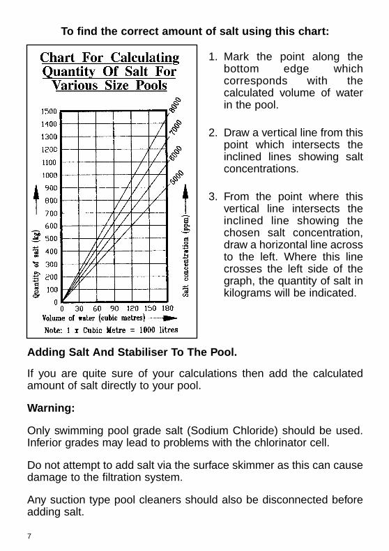
To find the correct amount of salt using this chart:
1. Mark the point along thebottom edge whichcorresponds with thecalculated volume of waterin the pool.
2. Draw a vertical line from thispoint which intersects theinclined lines showing saltconcentrations.
3. From the point where thisvertical line intersects theinclined line showing thechosen salt concentration,draw a horizontal line acrossto the left. Where this linecrosses the left side of thegraph, the quantity of salt inkilograms will be indicated.
Adding Salt And Stabiliser To The Pool.
If you are quite sure of your calculations then add the calculatedamount of salt directly to your pool.
Warning:
Only swimming pool grade salt (Sodium Chloride) should be used.Inferior grades may lead to problems with the chlorinator cell.
Do not attempt to add salt via the surface skimmer as this can causedamage to the filtration system.
Any suction type pool cleaners should also be disconnected beforeadding salt.
At the same time add the recommended quantity of cyanuric acidstabiliser. This is most important as your Surechlor will not operateefficiently during summer months without the correct level ofstabiliser in the pool. Recommended level for maximum efficiency isbetween 30 and 60 mg/l (ppm). pH buffer can also be added now ifrequired.
Dissolving The Salt
Before attempting to operate the Surechlor 3000 cell, the salt mustbe allowed to fully dissolve in the pool water. This is the bestachieved (after allowing sufficient time for the glue on the pipe fittingsto set properly) by running the filter pump without the cell operating(i.e. with CHLORINE CONTROL turned to the “OFF” position) for 24hours to circulate the water.
To assist the dissolving of the salt, regularly brush the floor of thepool with a pool broom until the salt has dissolved.
When The Salt Has Dissolved
With the pump still operating, rotate the Chlorine Control knob fullyin a clockwise direction. The Monitor should read in the NORMALrange i.e. green leds on.
Your Surechlor is now generating chlorine!
Should the Led Salt Monitor read in the yellow region with theChlorine Control knob fully advanced, do not be concerned, justallow the system to run for another 24-48 hours. If the displaycontinues to give a low reading after this period, press the Salt TestButton (with the system running) and note which led operates on thedisplay.
If the water temperature is around 25°C and the cell is relativelyclean, this reading will indicate salt concentration. If it confirms thesalt level is low (i.e. yellow leds) then add more salt gradually over aperiod of days until the display reads high in the Normal band (i.e.green leds). Continue brushing floor of pool until the additional salthas dissolved.
8

9
SETTINGS AND CONTROLS
POWER PAK OPERATION
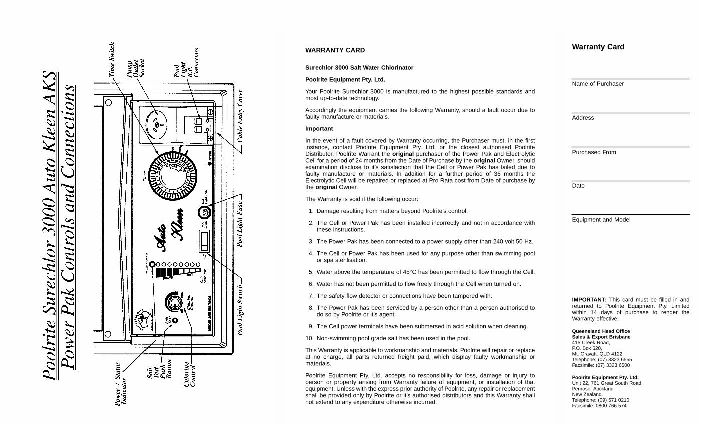
POWER/STATUS INDICATOR — all models
This is illuminated when power is applied to the Power Pak.The power/status led changes colour from red to green depending onthe output polarity. It flashes orange to indicate a water detectionfault.
If there is a time switch fitted and it is in the the OFF or AUTOcondition the lamp will be off.
CHLORINE CONTROL — all models
Because your Surechlor 3000 has been designed to operate over awide range of salt levels, water temperature, running time, etc., aChlorine Control has been provided to compensate for thesevariations.
When first starting the unit and where maximum chlorine productionis needed the control knob should be rotated fully clockwise so theLed Salt Monitor is indicating maximum on the Chlorine Output scaleor as high as prevailing conditions will allow.
The Chlorine Control knob on all Surechlor 3000 models can beturned fully clockwise if higher salt levels are used without the risk ofdamage occurring, due to the incorporation of electronic outputlimiting on all NSC & AKS 3000 model chlorinators.
To operate the filter pump only without the cell, simply turn theChlorine Control Knob fully anti-clockwise to the OFF position.

LED SALT MONITOR
This multi-function Led Salt Monitor has beenprovided to allow monitoring of the currentpassing through the electrolytic cell to allowyou to gauge the operation of the cell andthe chlorine production. This assists indetermining the condition of the electrolyticcell.
It also provides a simple means of indicatingthe salt level of the pool water when the SaltTest Button is pressed.
With the cell operating correctly the led bar graph should be withinthe Normal green band. Should the leds drop below the green bandinto the yellow the salt level may be too low. This should be checkedand adjusted if found necessary.
All Models Coded NSC/AKS...-S
These models are designed to operate by manually switching poweron and off to the Power Pak (and pool pump) via the standard 240volt power point.
If required, an external time switch can be used to control the dailyoperation of the filter systems associated with these models byplugging the Surechlor 3000 supply lead into the output of a suitabletime switch after setting the Led Salt Monitor correctly with theChlorine Control.
10
11
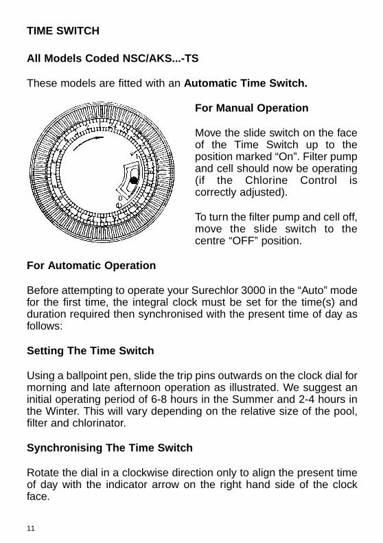
TIME SWITCH
All Models Coded NSC/AKS...-TS
These models are fitted with an Automatic Time Switch.
For Manual Operation
Move the slide switch on the faceof the Time Switch up to theposition marked “On”. Filter pumpand cell should now be operating(if the Chlorine Control iscorrectly adjusted).
To turn the filter pump and cell off,move the slide switch to thecentre “OFF” position.
For Automatic Operation
Before attempting to operate your Surechlor 3000 in the “Auto” modefor the first time, the integral clock must be set for the time(s) andduration required then synchronised with the present time of day asfollows:
Setting The Time Switch
Using a ballpoint pen, slide the trip pins outwards on the clock dial formorning and late afternoon operation as illustrated. We suggest aninitial operating period of 6-8 hours in the Summer and 2-4 hours inthe Winter. This will vary depending on the relative size of the pool,filter and chlorinator.
Synchronising The Time Switch
Rotate the dial in a clockwise direction only to align the present timeof day with the indicator arrow on the right hand side of the clockface.

Automatic Operation Switch Setting
Move the slide switch on the face of the Time Switch down to theposition marked “AUTO”. Filter pump and cell should now operatewhen the next ON cycle is detected (if the Chlorine Control iscorrectly adjusted).
To manually turn the filter pump and cell off, move the slide switch tothe centre “OFF” position.
Underwater Pool Light Models
(all models coded NSC/AKS ...TS-DL)
These models are fitted with an automatic Time Switch and aseparate, dedicated power supply to operate a pool light.
Special B.P. Connectors on the bottom of the recess on the righthand side of the enclosure has been provided for easy connection ofa standard 12 volt underwater pool light rated at 100 watts or less,such as the Poolrite “Trimlite” unit.
Independent operation of the pool light is then controlled by therocker switch labelled “POOL LIGHT” at the bottom of the controlpanel.
12

13
HOW YOUR SURECHLOR 3000 SALT WATERCHLORINATOR WORKS.
Common salt (Sodium Chloride) is made up of two elements, sodiumand chlorine. When your Poolrite Surechlor 3000 is installed ameasured amount of salt is dissolved in the pool water to make itslightly salty (about 15% of the salt found in sea water).When the filter system is operating this pool water also flows throughthe clear Electrolytic Cell where a very low voltage electric current ispassed through the salty water which causes chlorine to beproduced. This chlorine instantly dissolves in the pool water.Some ozone and other gasses are also produced as a by-product ofthe process.
Put very simply, this dissolved chlorine starts to destroy bacteria,viruses and algae almost instantly and in doing so reverts back todissolved salt. This cycle continues with more new chlorine beinggenerated from the salty water in the cell, the pool being sanitisedand the chlorine reverting back to dissolved salt.
As your Surechlor 3000 is operating each day during normaloperation of the filtration system, solid particles are trapped by thefilter while your Surechlor 3000 sanitises the water to make it safe,clear and sparkling.

MAINTENANCE OF POOL WATER CHEMISTRY
CHLORINE LEVEL
Using a 4 in 1 test kit, test the pool water daily at first then at leastonce a week to ensure sufficient chlorine level is being maintained.A free chlorine reading of 1.5 mg/l (ppm) and above is adequatewhen taken near the skimmer.
Should the level fall below 1.5 mg/l (ppm) check salt level and/orincrease the daily running time of filter and Surechlor.
pH CONTROL
Check the pH of your pool at least once a week after your Surechloris first installed.
The pH of your pool is a measure of the balance between acidic andalkaline products in the water. It is measured on a scale of 0 to 14.
A pH level of 0.0 is pure acid.
A pH level of 7.0 is neutral.
A pH level of 14.0 is pure alkali.
The recommended range for swimming pool water is 7.2 to 7.6 forconcrete pools, and you should refer to your builder’srecommendations for other types of pools.
Controlling the pH of your pool is vital to the correct operation of theSurechlor and the effectiveness of the chlorine produced to kill algaeand bacteria and the comfort of bathers. Correct pH also effects thelife of metals, cement products and plaster finishes in the pool.
If a pH test indicates a low pH then add sodium bicarbonate (pHbuffer) to raise the pH. If the pH is high then add acid (hydrochloricor dry acid) to lower the pH.
14

15
Adding Acid
If the addition of acid is indicated, be careful not to add too much atone time as this may destroy total alkalinity or cause harmful effects.We suggest you turn on the filter, add the acid to water in a plasticwatering can to dilute, then distribute evenly around the pool awayfrom walls, steps, etc.
TOTAL ALKALINITY
Check the Total Alkalinity at least once a month and maintain correctlevel for proper pool water balance.
Total Alkalinity is a measure of the acid neutralising capacity of waterwhich indicates its ability to buffer (resist) changes in pH.
The addition of sodium bicarbonate will increase the level and acidwill reduce it. Measurements can be made with a 4 in 1 test kit.
Correct levels depend on other factors such as hardness, pH andtemperature, however the following levels can be used as a guide.
Concrete Pool — 150 to 250 mg/l
Fibreglass Pools — 80 to 100 mg/l max.
Vinyl Lined Pools — Above 100 mg/l
CYANURIC ACID STABILISER
Have a water sample tested at least every 4 months by your poolshop to determine the level of Cyanuric Acid Stabiliser. It is mostimportant that a level between 30 and 60 mg/l (ppm) be maintainedin order for your Surechlor to work efficiently during Summer if yourpool is outdoors.
CALCIUM HARDNESS
Calcium Hardness is a measure of the calcium compounds dissolvedin the water.
Recommended levels should be as low as practical to minimiseproblems with calcium deposits forming in the cell, therefore don’tadd any further calcium chloride (to raise hardness) or calcium

hypochlorite (granular chlorine) to your pool once the decision hasbeen made to install saltwater chlorination.
Warning
Water supplies from bores/rivers/dams etc., can be high in mineralcontaminants resulting in poor chlorine production, therefore watermay require additional chemical treatment.
ALGAECIDES
Adherence to the above water chemistry recommendations shouldalleviate the need to use algaecides in your pool.
MAINTAINING SALT LEVELS
Before attempting to add salt to your pool the Surechlor 3000 Cellshould first be cleaned if necessary as per instructions. Then, withthe filter and cell operating, the Salt Test Push Button should bepressed and the reading on the Led Salt Monitor noted.
If this reading indicates in the yellow region then the level of salt istoo low and must be increased. This will normally be required about4 times a year on average domestic pools but will vary depending onthe type of filtration, climatic conditions, etc.
Note : Higher salt levels are recommended in hot weather conditionswhere maximum chlorine production is needed. We suggest levelsas high as 8000 mg/l (ppm) in these situations.
MAINTENANCE OF YOUR SURECHLOR 3000 AKS MODEL
Your Surechlor 3000 Auto Kleen has been designed to operate forextended periods with a minimum of maintenance. The cell cleaningfunction is performed automatically via the inbuilt electronic controlmodule.
In the unlikely event that your cell needs to be manually cleaned,follow the instructions under maintenance of your Surechlor 3000NSC160, NSC210, NSC310, NSC620.
16

17
MAINTENANCE OF YOUR SURECHLOR 3000NSC160, NSC210, NSC310, NSC620
Your Surechlor 3000 has been designed to operate for extendedperiods with a minimum of maintenance, however periodic cleaningof the cell electrodes is required.
Cell Cleaning
1. Remove Surechlor Power Pak plug from 240 volt power point.2. Remove cell from plumbing line.3. Turn cell upside down (ports facing upwards) and place on a
level non-metallic surface in a well ventilated area.
Warning: Rubber gloves and protective eyeware must be wornbefore proceeding to the next steps!
4. Prepare an 8:1 acid cleaning solution by firstly measuring 2 litresof water into a plastic bucket and then carefully adding 250ml ofHydrochloric Acid. Stir thoroughly with a wooden stick.
5. Carefully pour sufficient cleaning solution into upturned cell soas to fully cover metal electrodes.
6. Allow to stand for 10 minutes then flush out with clean water.Do not put used acid solution into pool.
7. If electrodes still show white deposits, repeat the above steps.
Note: It isrecommended that awarm water detergentsolution be used tosoak the electrodes atthis point if there is anyevidence of body fats,oils or greases.
8. Re-fit cell to plumbing line making sure both rubber “O” ring sealsare in place.
9. Re-connect plug of Power Pak to 240 volt power point and switch on.10. Reset time switch if fitted.
OVERLOAD PROTECTION
In addition to the electronic current limiting and overload protectioncircuit built into the Power Pak, there is an internal Type 205/3.15A/Slow Blow fuse fitted to further protect the power supply for theCell.
Should this fail (as indicated by the Led Salt Monitor failing to showany reading despite the Chlorine Control knob being correctly setand the Top Indicator Led being ON), it is an indication that a faulthas occurred related to the electronic circuitry.
In the unlikely event that this should occur, please call for service.
HOW LONG SHOULD YOUR CHLORINATOR CELL LAST?
When installed on a normal domestic pool, Poolrite cell electrodeshave a nominal life expectancy of approximately five years if they arecorrectly maintained.
With operating conditions varying widely in different pools, theactual life of the cell electrodes can be quite different from thenominal life.
For example, a chlorinator cell operating for only 3 hours daily can beexpected to last twice as long as the same cell operating for 6 hoursdaily. Likewise, the same cell operating 24 hours daily may sufferelectrode failure after just one year!
18

19
To assist you in prolongingthe life of your Surechlor3000 Cell Electrodes, wehave provided this chartof Common Causes OfPremature Cell Failurebased on our extensiveexperience in designing,manufacturing andservicing salt waterchlorinators in Australia.
In order to achieve thelongest possible life fromyour Surechlor 3000 cell,we recommend that theowner bear theseimportant points in mindas it is sometimes difficultto determine which ofthe above points wasresponsible wheninspecting a cell whichhas failed prematurely.
CUSTOMER RESPONSIBILITIESBEFORE YOU CALL FOR SERVICE read the Operating Instructions carefully andcheck the following points which are your responsibility.
A service charge will be made for service as a result of:Power point not turned on or faulty (check with another appliance).Time switch incorrectly set.Unit incorrectly installed.Pump not plugged into Surechlor Pump Outlet Socket.Switches and controls incorrectly set.Poor water chemistry (Salt Level, pH, etc).Cell not being cleaned (acid washed) properly.Poor water flow (check filter is clean / pump operating / skimmer free of obstructions).Unit being tampered with by unauthorised persons.Underwater light connection not wired correctly or globe blown etc (TS-DL models only).
Common Causes OfPremature Cell Failure
a) Operating the cell with too little saltin the water (this can often happenafter heavy rain).
b) Excessive accumulation of calciumdeposits on electrodes.
c) Low water flow through cell (poorfilter maintenance or a faulty pumpare typical causes).
d) Physical damage to electrodecoating caused by scraping with ascrewdriver, etc.
e) Cleaning of electrodes in too strongan acid solution (greater than 1 parthydrochloric acid in 8 parts water).
f) Acid washing for too long (10-15minutes max. In contact with 1:8acid/water should be more thansufficient).

20
Led
Sal
t M
onito
r R
eads
Lo
wLo
w
Chl
orin
e I
n P
ool
Ope
ratio
nal
Che
ck
List
Filt
er
Pum
p W
ill
Not
R
un
Err
atic
R
eadi
ng
On
Mon
itor
Pow
er
Led
Not
Il
lum
inat
edN
o C
hlor
ine
Out
put
Und
erw
ater
Li
ght
Not
Wor
king
Pro
babl
e C
ause
Rem
edy
●●
●●
Cel
l dir
tyV
isua
lly c
heck
cel
l and
aci
d w
ash
cell
if di
rty
●●
●●
Low
sal
tU
se S
alt
Test
But
ton
and
add
salt
if re
quire
d
●Lo
w w
ater
tem
pera
ture
Nor
mal
for
Win
ter
(acc
ept
low
er r
eadi
ngs)
●●
●P
oor
wat
er f
low
Filt
er d
irty
/lea
ves
in b
aske
ts/v
alve
s cl
osed
●In
suffi
cien
t da
ily r
unni
ng t
ime
Incr
ease
run
ning
tim
e of
filt
er a
nd S
urec
hlor
●In
suffi
cien
t ch
lorin
e st
abili
ser
Hav
e po
ol c
heck
ed a
nd a
dd s
tabi
liser
if n
eede
d
●●
●●
Pow
er p
oint
not
sw
itche
d on
Che
ck p
ower
poi
nt
●●
●●
Exc
essi
ve a
ir in
cel
lP
ump
lid/p
ipe
conn
ectio
ns/lo
w p
ool w
ater
●E
xter
nal p
ool l
ight
fus
e bl
own
Che
ck a
nd r
epla
ce f
use
if ne
cess
ary
●G
lobe
in li
ght
faile
dR
epla
ce g
lobe
or
call
serv
icem
an
●P
ool l
ight
sw
itch
not
turn
ed o
nC
heck
and
sw
itch
on if
nec
essa
ry
●●
●“C
hlor
ine
Con
trol
” tu
rned
dow
nC
heck
Chl
orin
e C
ontr
ol K
nob
setti
ng
●●
●In
tern
al f
use
blow
nC
all s
ervi
cem
an
●●
●●
Tim
e sw
itch
not
corr
ectly
set
Che
ck s
ettin
gs a
nd r
ead
inst
ruct
ions
●●
●P
ump
not
runn
ing
Che
ck m
otor
ove
rload
fro
m b
lock
age
in p
ump
●●
●●
●●
Pum
p pr
oble
ms
Che
ck fo
r lo
cked
rot
or o
r ca
ll se
rvic
eman
●●
●P
ump
not
plug
ged
into
uni
tC
heck
pum
p is
plu
gged
into
Pow
er P
ak

ELECTRICAL SPECIFICATIONSPOOLRITE SURECHLOR 3000 SERIES
SALT WATER CHLORINATORS
INPUT = 240V / 50Hz
POWER CONSUMPTION (Max.):NSC160-S/NSC160-TS = 180 VA AKS150 S/TS = 180 VANSC160-TS-DL = 330 VA AKS150 TS-DL = 330 VANSC210-S/NSC210-TS = 250 VA AKS250 S/TS = 250 VANSC210-TS-DL = 400 VA AKS250 TS-DL = 400 VANSC310-S/NSC310-TS = 400 VA AKS350 S/TS = 400 VANSC310-TS-DL = 550 VA AKS350 TS-DL = 550 VANSC620-S/NSC620-TS = 400 VA AKS700 S/TS = 800 VA
OUTPUT (Max.):Pump Socket = 240V 50Hz
= 1.5Kw (2.0HP)= 8.0A
Cell NSC160 Series = 9.0VDC 15A AKS150 Series = 8.0VDC 15ANSC210 Series = 9.0VDC 21A AKS250 Series = 8.0VDC 21ANSC310 Series = 9.0VDC 31A AKS350 Series = 8.0VDC 31ANSC620 Series = 16VDC 31A AKS700 Series = 12VDC 31A
Pool Light = 12VAC 100W
OVERLOAD PROTECTION:● Electronic current limiting on Cell output (all models).● Replaceable fuses as follows:)Cell Fuse (all models) = Type-205 / Slow Blow / 3.15A (Fitted Internally)Pool Light Fuse (if fitted) = Type 3AG / 10A (Fitted Externally)
APPROVALS● All Poolrite Surechlor 3000 Salt Water Chlorinators have been fully tested
and approved by the NSW Office of Energy and have been issued with aCertificate of Approval N/14151.
● The Power Pak Enclosure is rated as complying with IP24 as per AS1939-1990and as such can be legally installed within the designated Pool Zone as definedin section 7 of AS/NZS 3000/2000 Wiring Rules.
Poolrite Equipment Pty. Ltd. reserves the right to change these specificationswithout prior notification.
21