warning caution - korgi.korg.com/uploads/support/exb_moss_e_633662326168590000.pdf · moss...
TRANSCRIPT

2
WarningWhen installing, servicing, or replacing parts for this product, do not perform any action that is not prescribed in theowner's manual.Do not apply excessive force to the electronic components or connectors on the circuit board, and do not disassemble it.Electrical shock, fire, or malfunction may result.Before installing this product, disconnect the power supply cable of the device in which it is being installed, and discon-nect any cables that connect peripheral devices. Failure to do so may cause electrical shock or malfunctions.
CautionDo not allow this product to become wet, and do not place objects on top of it. Doing so will cause malfunctions.Before touching this product, touch a metal part of the device into which it will be installed, so that any static electricityin your body will be discharged. Failure to do so will risk damaging the electronic components by static electricity.When handling this product, be careful not to touch the leads (wires protruding from the electronic components) on therear side of the circuit board. Injury may result.When installing this product, do not touch any unrelated parts or circuit boards. Electric shock or malfunction may result.When installing this product, be careful not to cut yourself on any sharp edges or parts of this product or of the device intowhich this product is being installed.When installing this product, be careful not to drop screws etc. into the device into which this product is being installed.
The manufacturer makes no warrantee regarding possible malfunctions or damage that may result from improper use or
modification. The manufacturer also will take no responsibility for any damages that may result from loss or disappear-
ance of data.
Installing this productFor the procedure of installing this product, refer to the owner's manual of the device into which the product is beinginstalled. If you have any questions, please contact your local Korg distributor.
Cautions when installing an option boardIn order to install the board correctly, please pay attention to the following points.Be careful of static electricity, which may damage components inside the product or on the board. Before beginning theinstallation, touch an unpainted metal part of the chassis or the grounding terminal of a grounded device to discharge anystatic electricity that may be present in your body.Perform the installation according to the steps given in the directions, making sure that the board is installed correctly andin the correct orientation.Verify that the option board has been installed correctly. If installation is incorrect, faulty connections or a shorted powersupply can cause malfunctions.All the screws that are removed will be used, so be careful not to lose any.Using screws of the incorrect shape or length can cause malfunctions or damage to the product. Use only the screws thatwere included with the option board or the screws that were fastened in the instrument.When installing or removing the board, be careful not to drop parts or the option board into the instrument.Make sure that the attaching screws are tightened firmly, and are not loose.Handle the board with care. Subjecting it to physical shock (by dropping or pressing it) may cause damage or malfunctions.Be careful not to touch any exposed metal portions of the circuit board, or any parts that are not essential to the installationprocess.

3
Installing this product ..................................................... 2
Cautions when installing an option board .................... 2
1. Introduction ................................................................. 4Features of the EXB-MOSS .......................................................... 4
2.The structure of bank F programs.............................. 5Program structure .......................................................................... 5
Features of the oscillator ............................................................... 6
3. Bank F operations ....................................................... 7Loading the preset programs......................................................... 7
Selecting a program/combination .................................................. 7
Editing a program .......................................................................... 7
Editing a combination .................................................................... 8
Sequencer and Song Play modes ................................................. 9
Control change transmission/reception for the EXB-MOSS ........ 10
4. Parameters ................................................................. 11Program mode ........................................................................... 11
Program P0: Play ...............................................................................11
Program P1: Edit-Basic ......................................................................12
Program P2: Edit-Pitch .......................................................................36
Program P3: Edit-Filter .......................................................................38
Program P4: Edit-Amp .......................................................................40
Program P5: Edit-Common LFO ........................................................43
Program P6: Edit-Common EG ..........................................................45
Program P7: Edit-Arpeggiator ............................................................46
Program P8: Edit-Insert Effect ...........................................................46
Program P9: Edit-Master Effect ......................................................... 46
Combination mode .................................................................... 47
Combination P4: MOSS Setup ............................................... 47
Appendices .................................................................... 48Cautions when using bank F ....................................................... 48
Affix the Sondius-XG label ........................................................... 48
Modulation Source List ................................................................ 48
Voice Name List ........................................................................... 49

4
1. IntroductionThank you for purchasing the Korg EXB-MOSS DSPsynthesizer board. In order to enjoy long and trouble-free use, please read this manual carefully and use theEXB-MOSS correctly.
Before you use this product, you must read the“Safety Precautions” listed in the beginning ofthe Parameter Guide.
This manual explains the Bank F parametersthat are added when the EXB-MOSS isinstalled. For details on the parameters otherthan Bank F, refer to the TRITON’s ParameterGuide and Basic Guide etc.
Features of the EXB-MOSSThe EXB-MOSS is an option board containing aMOSS (Multi-Oscillator Synthesis System) tonegenerator with six-voice polyphony.The MOSS tone generator is a physical modeling tonegenerator that uses Sondius-XG* technology.When the EXB-MOSS is installed into the TRITON,you will be able to use the 128 MOSS tone generatorprograms in program bank F.Bank F is dedicated to MOSS tone generatorprograms. Bank F programs can be selected for atimbre/track in Combination, Song, and Song Playmodes. You can also create combinations or songsthat combine bank F programs with other programsfrom banks A–E or G.Broadly speaking, a MOSS tone generator programconsists of voice, EG, LFO, effect, and controlsections.The voice section contains an oscillator and a filter.— The oscillator provides two oscillators (1 and 2),which can use thirteen different oscillator algorithms,including Standard, Ring Modulation, VPM, Reso-nance, Organ Model, and Electric Piano Model. Theoscillator also provides a sub oscillator and a noisegenerator.— The filter provides five types of filters (two filtersystems), including a Human Voice Filter that lets yousimultaneously set two center frequencies, and a DualBand Pass Filter that lets you simulate the bodyresonances of a violin or guitar.Five EG units and four LFO units can be used tomodulate this voice section in order to create time-varying movement of pitch, tone, and volume.* This product was developed under license ofphysical modeling tone generator patents (http://www.sondius-xg.com) owned by Stanford UniversityUSA and Yamaha Corporation.

5
2.The structure of bank F programs
Program structureThe programs of bank F have the following structure.
OscillatorThis section produces the waveform that is the basisof the sound.Settings are made by the “Program P1: Edit-Basic”and “Program P2: Edit-Pitch” parameters.— OSC 1, 2Thirteen oscillator types (methods of sound genera-tion) are provided. Of these, you can select twooscillator types for use together, and make basicsettings for the pitch and waveform. However forsome oscillator types, only one type can be used.Settings are made by the parameters of “1–1: ProgBasic,” “1–2: OSC Basic,” “1–3: OSC1,” and “1–4:OSC2.”— Sub oscillatorOne of four basic waveforms can be selected. Its pitchcan be set in the same way as OSC1 and 2.These settings are made by the parameters of “1–2:OSC Basic” and “2–3: SubOSC P.Mod.”— Noise generatorThis produces white noise, which can be passedthrough a multi-mode filter (low pass filter, high passfilter, band pass filter).Settings are made by the “1–5: Noise Generator”parameters.
MixerThis section mixes the signals from oscillators 1 and2, the sub oscillator, the noise generator, and thefeedback from the amp, and outputs the result tomulti-mode filters 1 and 2 (filter section).Settings are made by the “1–6: Mixer” parameters.
Mixer
Oscillator 1
Oscillator 2
Sub Oscillator
Noise Generator
Feedback
Amp1
Amp2
PanLPF/HPF/BPF/BRF/2BPF
LPF/HPF/BPF/BRF/2BPF
Filter 1
Filter 2
Insert Effect
MasterEffect
Master EQ
L/MonoR
OSC Mixer
Filter AMP
FX
EG1 EG2 EG3 EG4 Amp.EG
LFO1 LFO2 LFO3 LFO4
Joy Stick, Ribbon Controller& other controllers
�
INDIVIDUAL 1, 2, 3, 4
FilterThis section processes the waveform by attenuating orboosting specific frequency ranges. Two multi-modefilters are provided. As filter types, you can selectfrom low pass, high pass, band pass, band reject, ordual band pass filters. These filters can be used tomodify the brightness of the sound. You can alsoselect the connection routing between the two filtersand the mixer and amp.Settings are made by the “Program P3: Edit-Filter”parameters.
AmpThis section modifies the volume of the sound that isoutput from the filter. There are two independentamps. The signal that is input to each will depend onthe filter connections. The amp section also provides aspecial envelope generator for controlling the amp(Amp EG).These settings are made by the “Program P4: Edit-Amp” parameters.
EffectThis section applies effects to the signal that is outputfrom the amp. It has the same parameter structure asthe programs of other banks.Settings are made by the “Program P7: Edit-Arpeggiator” and “Program P8: Edit-Insert Effect”parameters.
LFOThis section provides four LFO units. Each LFO canbe used as a modulation source for various param-eters, to apply cyclic change to the sound.Settings are made by the “Program P5: Edit-CommonLFO” parameters.
6
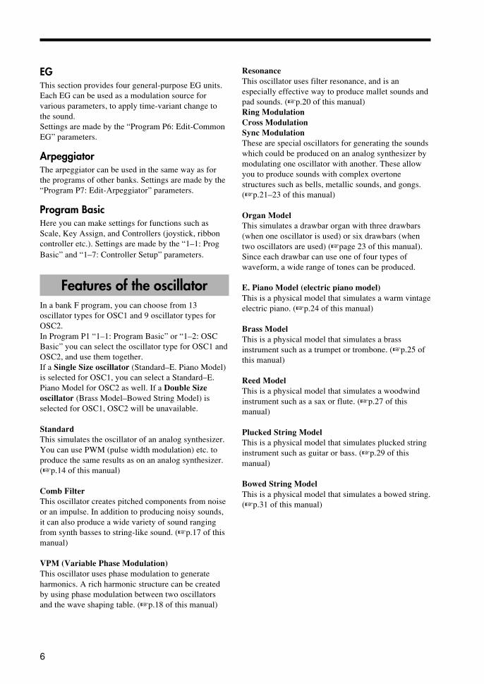
EGThis section provides four general-purpose EG units.Each EG can be used as a modulation source forvarious parameters, to apply time-variant change tothe sound.Settings are made by the “Program P6: Edit-CommonEG” parameters.
ArpeggiatorThe arpeggiator can be used in the same way as forthe programs of other banks. Settings are made by the“Program P7: Edit-Arpeggiator” parameters.
Program BasicHere you can make settings for functions such asScale, Key Assign, and Controllers (joystick, ribboncontroller etc.). Settings are made by the “1–1: ProgBasic” and “1–7: Controller Setup” parameters.
Features of the oscillatorIn a bank F program, you can choose from 13oscillator types for OSC1 and 9 oscillator types forOSC2.In Program P1 “1–1: Program Basic” or “1–2: OSCBasic” you can select the oscillator type for OSC1 andOSC2, and use them together.If a Single Size oscillator (Standard–E. Piano Model)is selected for OSC1, you can select a Standard–E.Piano Model for OSC2 as well. If a Double Sizeoscillator (Brass Model–Bowed String Model) isselected for OSC1, OSC2 will be unavailable.
StandardThis simulates the oscillator of an analog synthesizer.You can use PWM (pulse width modulation) etc. toproduce the same results as on an analog synthesizer.(�p.14 of this manual)
Comb FilterThis oscillator creates pitched components from noiseor an impulse. In addition to producing noisy sounds,it can also produce a wide variety of sound rangingfrom synth basses to string-like sound. (�p.17 of thismanual)
VPM (Variable Phase Modulation)This oscillator uses phase modulation to generateharmonics. A rich harmonic structure can be createdby using phase modulation between two oscillatorsand the wave shaping table. (�p.18 of this manual)
ResonanceThis oscillator uses filter resonance, and is anespecially effective way to produce mallet sounds andpad sounds. (�p.20 of this manual)Ring ModulationCross ModulationSync ModulationThese are special oscillators for generating the soundswhich could be produced on an analog synthesizer bymodulating one oscillator with another. These allowyou to produce sounds with complex overtonestructures such as bells, metallic sounds, and gongs.(�p.21–23 of this manual)
Organ ModelThis simulates a drawbar organ with three drawbars(when one oscillator is used) or six drawbars (whentwo oscillators are used) (�page 23 of this manual).Since each drawbar can use one of four types ofwaveform, a wide range of tones can be produced.
E. Piano Model (electric piano model)This is a physical model that simulates a warm vintageelectric piano. (�p.24 of this manual)
Brass ModelThis is a physical model that simulates a brassinstrument such as a trumpet or trombone. (�p.25 ofthis manual)
Reed ModelThis is a physical model that simulates a woodwindinstrument such as a sax or flute. (�p.27 of thismanual)
Plucked String ModelThis is a physical model that simulates plucked stringinstrument such as guitar or bass. (�p.29 of thismanual)
Bowed String ModelThis is a physical model that simulates a bowed string.(�p.31 of this manual)

7
3. Bank F operations
Loading the preset programsPlease load the “EXBMOSS-00FD” data from thefloppy disk included with the EXB-MOSS. For detailson the procedure, refer to “Disk mode” of the TRI-TON Basic Guide. The floppy disk contains thefollowing data.
MOSS.PCGProgram Bank A*, B*, FCombination Bank A*, BDrum Kits 00–15(A/B)*Arpeggio Pattern 000–199(A/B)*Global setting*MOSS.SNGCue ListDemo Song "Feet Hurt MOSS" by Scott Frankfurt
©1999 Bleach Bros. Music([email protected]) - all rights reserved.
Program bank F contains programs that use the EXB-MOSS.Combination bank B contain combinations that usebank F programs together with the TRITON’spreloaded programs of banks A and B.* Same as the preloaded data of the TRITON.
When you load MOSS.PCGPrograms, combinations, drum kits, arpeggio patterns,and global settings will be written into the TRITON’sinternal memory.
When you load MOSS.PCG, all the currentcontents of internal memory will be erased andoverwritten.
When you load MOSS.SNGDemo songs that use the bank F programs etc. ofMOSS.PCG will be loaded. These songs can beplayed in Sequencer mode.
When you select and load MOSS.SNG, all thecurrent contents of sequencer memory will beerased and overwritten.
Selecting a program/combination
In “Program P0: Play,” you can select a bank Fprogram 000–127 in the same way as for banks A–E.You can also select programs from the “Category/Program Select” menu or the “Bank/Program Select”menu.Combinations can be selected in “Combination P0:Play,” and also from the “Category/CombinationSelect” menu or the “Bank/Combination Select”menu.For a list of the programs/combinations in theincluded floppy disk, refer to “Voice Name List” onp.49 of this manual.
Editing a programIf a bank F MOSS tone generator program is selectedin “Program P0: Play,” you can use P1–P9 to edit theprogram parameters. For details on the programparameters, refer to the “Parameters” section thatbegins on p.11 of this manual.
The performance editor parameter “PitchStretch” of “Program P0: Play” cannot be usedfor bank F programs.

8
Editing a combinationYou can select a bank F program for a timbre in acombination, and use it in the combination togetherwith programs of banks A–E and G. Different MOSStone generator programs from bank F can be selectedfor two or more timbres, and used multi-timbrally. Inthis case, the total polyphony of the MOSS tonegenerator programs will be six voices.
Insertion/master effect settings and the routingto the individual audio outputs cannot be madeindependently for multiple timbres.
If you change programs while a bank Fprogram is sounding, the bank F program willstop sounding.
When playing multi-timbrally and a bank Fprogram is being sounded, selecting a bank Fprogram for the timbre number prior to thattimbre number will cause noise to be heard inthe currently-sounding bank F program.
Editing a combinationHere’s how to select programs and set the parametersthat determine how each program will sound.
(1) Select Combination P0: Play.For details on how to enter each page, refer to p.52“Combination mode” in the TRITON Basic Guide.
(2) Select the combination number thatyou wish to edit.
(3) Select the Combination P4: MOSSSetup tab.Before you select a bank F program, make settingshere to specify how the MOSS tone generator willsound.
(4) Set the Voice Allocation Reserveparameter to specify the polyphony foreach timbre.For each timbre, specify the number of voices thatwill be allocated when a MOSS tone generatorprogram is selected. A total of six voices can beallocated.For example, you might allocate two voices to timbre1 for a bass-type MOSS program, and up to fourvoices to timbre 2 for an electric piano MOSSprogram.
These settings have no effect on the programsof banks A–E and G.When the timbre bank/program is changed toswitch a timbre from a bank F program to abank A–E or G program, the bank A–E or Gprogram will sound as usual.
When the timbre bank/program is changed toswitch a timbre from a bank A–E or Gprogram to a bank F program, it will soundaccording to the setting you make here.Timbres for which a value of 0 is set will notsound if a bank F program is selected.
(5) Set the MOSS BUS Select Reference.The bank F programs will be routed to the insertion/master effects or individual audio output according tothe settings of the timbre you select here.
The timbre 1–8 you select here does not haveto be using a bank F program.
Bank F programs can be used for two or more timbresaccording to the “Voice Allocation Reserve” setting.However, settings for insertion/master effects androuting to individual audio outputs can not be madeindependently for two or more timbres.Timbre settings for insertion/master effects androuting to individual audio outputs are made in theProgram P8: Routing tab. Use the following procedureto make settings.Example)1. Set “MOSS BUS Select Reference” to Timbre 1.2. In the Program P8: Routing tab, set the timbre 1“IFX/Indiv.Out BUS Select” to L/R.All bank F programs that you selected will be sent toL/R (without using the insertion effects).3. Set the timbre 1 parameters “Send 1” and “Send 2”to 064 and 127 respectively.The signal will be sent to MFX1 and MFX2 at thespecified levels.4. If you wish to use an insertion effect, set “IFX/Indiv.Out BUS Select” to IFX1–IFX5. If you wish tooutput to the [AUDIO OUT INDIVIDUAL] 1–4 jacks,select 1–4, 1/2, or 3/4.

9
The actual levels of send 1 and 2 for a timbreusing a bank A–E or G program is determinedby multiplying the timbre setting by the sendlevel of the program, but for timbres that use abank F program, the send level setting of thetimbre will be the actual level.
This setting has no effect for bank A–E or Gprograms.
(6) Select Combination P1: Edit-Program/Mixer.
(7) In “Bank/Program,” select a bank Fprogram.Programs can also be selected from the “Category/ProgramSelect” menu or the “Bank/Program Select” menu.
(8) Use “Pan” to adjust the panpot of thetimbre.When a bank F program is selected, the Randomsetting will not be available. If Random is selected,the sound will be placed in the center, as with C064.
(9) Use “Volume” to adjust the volume ofthe timbre.
(10) Make settings for other parameters.In the same way as for programs of other banks, set theparameters of each timbre, and make arpeggiator settings andinsertion/master effect settings.However when a bank F program is selected for a timbre, thefollowing parameters will function as explained below.— “OSC Select” will have no effect. (Combination P2:OSC tab)— The “Detune” range will be ±100. Even if the absolutevalue of the parameter setting is greater than 100, the actualdetune value will be ±100 cents. (Program P2: OSC tab)— The Key Zone / Vel Zone “Top Slope” and“Bottom Slope” settings will have no effect. (ProgramP4: Key Z, Vel Z tabs)
Sequencer and Song Playmodes
Bank F programs can be selected for playback of asong or Standard MIDI File, or for performance fromthe keyboard. In the same way as in a combination,bank F programs can be selected for two or moretracks and used multi-timbrally. In this case, the totalpolyphony of the bank F programs will be sixvoices.
Insertion/master effect settings and individualaudio output routing cannot be specifiedindependently for each track.
Details of the settings, the operation of each param-eter, and cautions are the same as for combinations.Refer to “Editing a combination” on p.8 of thismanual.� Sequencer P4: MOSS T01–08, MOSS T09–16 tabs� Song Play P1: MOSS T01–08, MOSS T09–16 tabs

10
Control change transmission/reception for the EXB-MOSS
In the same way as bank A–E or G programs, bank Fprograms can receive MIDI control changes CC#70–79, and can be operated by the front panel realtimecontrol knobs 1–4 in A-mode. In B-mode, CC#70–79can be assigned as knob functions, and used to controlthe program sound. These settings can be saved bywriting them in Program mode.� Refer to p.223 of the TRITON Parameter Guide.
CC#70: Sustain Level“Sustain Level” (Program P4: AmpEG tab, Program P6)
This controls the EG that is selected by FilterEG (Program P3: Filter 1/2 tab) and AmpLevel EG (Program P4: Amp 1/2 Level tab).
CC#71: Filter Resonance Level“Filter A Resonance” (Program P3: Filter 1/2 tab)“Filter B Resonance” (Program P3: Filter 1/2 tab)
CC#72: Release Time“Release Time” (Program P4: AmpEG tab, Program P6)
This controls the EG that is selected by FilterEG (Program P3: Filter 1/2 tab) and AmpLevel EG (Program P4: Amp 1/2 Level tab).
CC#73: Attack Time“Attack Time” (Program P4: AmpEG tab, Program P6)“Time Modulation At” (Program P4: AmpEG tab,Program P6)
This controls the EG that is selected by FilterEG (Program P3: Filter 1/2 tab) and AmpLevel EG (Program P4: Amp 1/2 Level tab).
CC#74: Low Pass Filter Cutoff Frequency“Filter A Frequency” (Program P3: Filter 1/2 tab)“Filter B Frequency” (Program P3: Filter 1/2 tab)
CC#75: Decay Time“Decay Time” (Program P4: AmpEG tab, ProgramP6: EG1–4 tabs)“Slope Time” (Program P4: AmpEG tab, Program P6:EG1–4 tabs)
This controls the EG that is selected by FilterEG (Program P3: Filter 1/2 tab) and AmpLevel EG (Program P4: Amp 1/2 Level tab).
CC#76: Pitch LFO Speed“LFO1–4 Frequency” (Program P5: LFO1–4 tabs)
If LFO 1–4 is selected for Pitch ModulationAMS1, AMS2 (Program P2: OSC1/2 PitchMod. tab) or Common Pitch Modulation AMS(Program P2: Common Pitch Mod. tab), thiscontrol change message will control that LFO.
CC#77: Pitch LFO Intensity“Pitch Modulation AMS1 Intensity” (Program P2:OSC1/2 Pitch Mod. tab)“Pitch Modulation AMS2 Intensity” (Program P2:OSC1/2 Pitch Mod. tab)“Common Pitch Modulation AMS Intensity” (Pro-gram P2: Common Pitch Mod. tab)
If LFO 1–4 is selected for the correspondingAMS, this control change message will controlthat LFO.
CC#78: Pitch LFO Delay“LFO1, 2, 3, 4 Fade” (Program P5)
If LFO 1–4 is selected for Pitch ModulationAMS1, AMS2 (Program P2: OSC1/2 PitchMod. tab) or Common Pitch Modulation AMS(Program P2: Common Pitch Mod. tab), thiscontrol change message will control that LFO.
CC#79: Filter EG Intensity“Filter A EG Intensity” (Program P3: Filter 1/2 tab)“Filter B EG Intensity” (Program P3: Filter 1/2 tab)

11
4. Parameters
Depending on the oscillator types or effecttypes used by the programs, a certain intervalof time may be required after a program isselected until it actually changes.
0–2: ArpeggioHere you can perform simple editing of thearpeggiator.For details on the parameters, refer to p.3 “0–2:Arpeggio” of the TRITON’s Parameter Guide.
This document explains the parameters that appear thescreen pages that are added when the EXB-MOSS isinstalled. For details on the other screen pages, refer tothe Parameter Guide and Basic Guide etc. of theTRITON.In Program mode, you can use the Write Programpage menu command to write an edited program intothe specified program number.
When you press the front panel [REC/WRITE]key, the “Update Program” dialog box willappear. Here too, you can write to the cur-rently selected program.
Be sure to write important programs that youedit. If you turn off the power or select anotherprogram before you write, your edits cannot berecovered. Refer to “Saving data” on p.37 ofthe TRITON Basic Guide.
Program mode
Program P0: Play
0–1: Perf.Edit (Performance Edit)Here you can select a program and perform simpleediting.For details on the parameters, refer to p.1 “1. Programmode” of the TRITON Parameter Guide.Parameters that can be controlled from the PerformanceEditorOctave Octave of OSC1, OSC2, and Sub OSCPitch Cannot be used for bank F.OSC Balance OSC 1 and 2 levels of OSC Mixer 1
and 2Amp Level Output levelAttack Time Amp EG, EG1,2,3,4
Attack Time, Time Modulation At(controls the EG selected by Filter 1, 2,Filter EG, Amp 1, 2, and Amp LevelEG)
Decay Time Amp EG, EG 1, 2, 3, 4Decay Time, Slope Filter (controls theEG selected by Filter 1, 2, FilterEG,Amp1, 2, and Amp Level EG)
IFX Balance Wet/dry balance of each effect IFX1–5MFX Balance Master effect return 1, 2

12
Program P1: Edit-BasicHere, you can select programs and perform simpleediting.
1–1: Program Basic
1–1a
1–1b
1–1d
1–1c
1–1a: Multi OSC SetupHere, you can make settings for the oscillator.The parameters that are set in “1–3: OSC 1” and “1–4:OSC 2” will differ depending on the oscillator typethat is selected here. (Link: 1–2a, 1–2b)
OSC 1 (Oscillator 1 Type)[Standard…Bowed String Model]
Selects the oscillator type for oscillator 1.For details on the oscillator types, refer to “Features ofthe oscillator” on p. 4 of this manual.
Single SizeStandardComb FilterVPM (Variable Phase Moulation)ResonanceRing ModulationCross ModulationSync ModulationOrgan ModelE. Piano Model
Double SizeBrass ModelReed ModelPlucked String ModelBowed String Model
When Double Size (Brass Model, ReedModel, Plucked String Model, or BowedString Model) are selected, OSC 2 cannot beused.
OSC 2 (Oscillator 2 Type)[Standard…E. Piano Model]
Selects the oscillator type for oscillator 2. Refer to OSC 1.
1–1b: UnisonHere, you can make settings for unison mode.
Unison [OFF, 2voices, 3voices, 6voices]Specifies the number of notes which will be soundedin unison. With a setting of OFF, unison will not beused.The maximum polyphony will be three notes with asetting of 2voices, two notes for a setting of 3voices,and one note for a setting of 6voices.
Mode [Fixed, Dynamic]Specifies how the number of voices specified by the“Unison” setting will be allocated.With a setting of Fixed, the number of voicesspecified by the “Unison” setting will always sound.With a setting of Dynamic, the number of voices willbe determined by the current note-playing situation.
Detune [0…99]Detunes the notes that are sounded simultaneously bythe Unison function.
1–1c: Voice Assign ModeHere, you can specify how notes will sound whenkeys are pressed.
Poly, Mono (Single, Multi)Selects whether the sound will be played monophoni-cally or polyphonically.Poly: Polyphonic playingMono (Single): Single-triggered monophonic playingMono (Multi): Multi-triggered monophonic playing.
When Poly is selected, the Retrigger Controland Threshold parameters will be unavailable.
Retrigger (Retrigger Contol) [Off…MIDI:CC#83]“Retrigger” refers to the action of resetting the EG andLFO at the time of note-on (the EG will return to itsstart level, and the LFO will return to the beginning ofthe cycle of its waveform). Here you can select thecontroller which will specify whether or not the soundwill be retriggered when a note-on occurs.
Threshold (Retrigger Control Threshold) [1…127]Specifies the value at which EG and LFO will beretriggered by a note-on.The state of the controller selected by RetriggerControl (i.e., whether the controller value is above orbelow the specified Threshold value) will determinewhether or not the sound will be retriggered when anote-on occurs.

13
The operation of this function will differ depending onthe “Voice Assign Mode” setting.With a setting of Mono (Single), retriggering willoccur if the controller is above the threshold value. IfRetrigger Control is OFF, retriggering will not occur.With a setting of Mono (Multi), retriggering willoccur if the controller is below the threshold value. IfRetrigger Control is OFF, retriggering will alwaysoccur.
If a note-on occurs when all notes are off,retriggering will always occur.LFO’s whose Key Sync is turned OFF willnot be reset even if retriggering occurs.
Priority [Low, High, Last]Specifies the priority order that will be used when thenumber of keys pressed exceeds the maximumpolyphony.Low: The lowest note will take priorityHigh: The highest note will take priority
Last: The last-pressed note will take priority
HoldWhen this is checked, the note will continue to soundafter the key is released. However, if the EG selectedby “4–1: Amp1,” “Amp2” (normally the Amp EG isused) has a sustain level of zero, the note will decaynaturally.
1–1d: ScaleSpecifies the scale type
Type (Scale Type)[Equal Temperament…User Octave Scale 15]
Selects the basic scale for the internal tone generator.The user scales can be specified in Global mode “3–1:User Scale” (�page 127 in Parameter Guide).
Equal TemperamentThe most widely used scale, consisting of equally-spaced semitone steps.Pure MajorThe major chords of the selected key will be per-fectly in tune.Pure MinorThe minor chords of the selected key will be per-fectly in tune.ArabicThis reproduces a quarter-tone scale of Arabic mu-sic.PythagoreanA scale based on ancient Greek musical theory, suit-able for playing melodies.Werckmeister (Werkmeister III)An equal-tempered scale used in the later Baroqueperiod.
Kirnberger (Kirnberger III)A scale created in the 18th century, and used mainlyfor tuning harpsichords.SlendroAn Indonesian gamelan scale in which the octaveconsists of 5 notes.If the Key parameter is set to C, use the C, D, F, G,and A keys. (Other keys will produce the samepitches as equal temperament.)PelogAn Indonesian gamelan scale in which the octaveconsists of 7 notes.If the Key parameter is set to C, use only the whitekeys. (The black keys will produce the same pitchesas equal temperament.)StretchThis is a tuning used on acoustic pianos.User All Notes ScaleThis is the full-range scale (C-1=G9) that you cre-ate in Global mode “3–1b: User All Notes scale”(�page 121 in TRITON Parameter Guide).User Octave Scale 00–15This is the one-octave scale that you create in Glo-bal mode “3–1a: User Octave Scale” (�page 121in TRITON Parameter Guide).
Key (Scale Key) [C…B]Specify the tonic note of the selected scale. Thissetting has no effect for Equal Temperament,Stretch, or User All Note Scale .
If a scale other than equal temperament isselected, certain combinations of this param-eter and the “Key” parameter may cause thetuning of the base key (for example A=440Hz) to become incorrect. If this occurs, youcan adjust the “Master Tune” (Global P0:Basic tab).
Random [0…99]As this value is increased, the pitch of the note willbecome increasingly unpredictable. Normally you willleave this set at zero.Adjust this parameter when you wish to simulateinstruments whose pitch is naturally unstable, such astape-mechanism organs or acoustic instruments.

14
1–2: OSC Basic (Osillator Basic)
1–2a
1–2b
1–2c
1–2a: OSC 1 Multi OSC SetupSpecifies the basic pitch of oscillator 1
OSC 1 (Oscillator 1 Type)[Standard…Bowed String Model]
This shows the oscillator type that was selected in “1–1a: Multi OSC Setup.” This is linked with the identi-cally-named parameter in “1–1a: Multi OSC Setup.”
Octave [–2[32']…+1[4']]Specifies the basic pitch of oscillator 1 in steps of anoctave.32' is two octaves below, 16' is one octave below, 8'is standard pitch, and 4' is one octave above.
Transpose [–12…+12]Adjusts the basic pitch specified by “Octave” insemitone steps.
Tune [–50…+50]Makes fine adjustments to the pitch in one-cent steps.
F. Offset (Frequency Offset) [–10.0…+10.0]
Makes fine adjustments to the pitch in 0.1 Hz steps.
1–2b: OSC 2 Multi OSC SetupSelects the oscillator type for oscillator 2.
1–2c: Sub OSCMake basic settings for the sub oscillator.Parameters other than Waveform are the same as foroscillator 1.
Waveform [Saw…Sine]Select the waveform of the sub oscillator.
1–3: OSC1 (Oscillator 1)Make settings for each oscillator type. The oscillatortype is selected in “1–1a: Mult OSC Setup” or “1–2:OSC Basic.”The parameters that are displayed will depend on theselected oscillator type.
Standard
1–3a
1–3b
1–3c
This oscillator produces the waveforms used by ananalog synthesizer (sawtooth wave, pulse wave,triangle wave) and sine wave. Sawtooth wave, pulsewave and triangle wave waveforms can be modifiedusing waveform modulation. You can specify eithersawtooth wave or pulse wave as the main waveform,and mix triangle wave or sine wave with this foroutput. The level of these three waveforms can beadjusted independently.In addition, wave shaping can be applied to the outputof this oscillator.
Waveform modulationPulse width modulation (PWM) on an analog synthe-sizer produces time-varying change in the pulse widthof a pulse wave. The waveform modulation providedby the EXB-MOSS option is an extension of this,which varies not only the pulse width but also thewaveform of a sawtooth wave or triangle wave.Waveform modulation will affect the various wave-forms as follows.
Sawtooth wave
-99 -33 0 33 66 99
Waveform modulation will modify a sawtoothwaveform as shown below, creating time-variantchange in the sound.

15
When modulation is 0, the basic sawtooth waveformwill be produced, and when it is 99, a sawtooth waveof double the frequency will be produced. If themodulation value is a negative number, a differenteffect will result than with positive settings.
Pulse wave
-98 -33 0 33 66 98
Waveform (pulse width) modulation will modify apulse waveform as shown below, creating time-variantchange in the sound. When modulation is 0, a squarewave will be produced, and when it is 99, the pulsewidth will be 0, meaning that there will be no sound.If the modulation value is a negative number, theresults will be inverted.
Triangle wave
-99 -25 0 25 50 75 99
Waveform modulation will modify a ramp wave asshown below, creating time-variant change in thesound. When modulation is 0, a triangle wave willresult, and as the modulation value increases, thewaveform will become a ramp wave (a waveform inwhich the slope is broken in two). At a modulationvalue of 50, a trapezoidal wave will result, and at avalue of 99 the waveform will once again be a trianglewave. If the modulation value is a negative number,the results will be inverted.Compared to sawtooth orpulse waves, this waveform produces a strongfundamental with fewer overtones, making it particu-larly suitable for bass sounds etc.
1–3a: Wave
Main Wave [Saw, Pulse]Selects the main waveform. Select either Saw(sawtooth wave) or Pulse (pulse wave).
Level [0…99]Specifies the output level of the main waveform.
Wave Edge [0…99]Adjusts the amount of high-range overtones for themain waveform. As the pitch rises, this effect willbecome stronger, and in the low range there will belittle effect. Lower settings of this parameter willproduce a more mellow sound, and in the vicinity of 0the volume will also decrease.
Triangle Level [0…99]Specifies the output level of the triangle waveform. Itwill be output mixed with the main waveform.
Sine Level [0…99]Specifies the output level of the sine waveform. It willbe output mixed with the main waveform.
Phase Shift (Triangle & Sine Phase Shift)[–99…+99]
Specifies the phase difference between the mainwaveform and the triangle and sine waveforms. (Thetriangle and sine waveforms will always be in phasewith each other.)
1–3b: Waveform (Waveform Modulation)
Waveform[–99…+99]
Specifies the waveform. For the way in which thisvalue will affect the waveform, refer to the diagramsshown on the previous page for sawtooth wave, pulsewave, and triangle wave.
LFO [LFO1…LFO4]Selects the source LFO for waveform modulation.LFO settings are made in the “Program P5.”
Intensity (Waveform Modulation LFO Intensity)[–99…+99]
Specifies the depth and direction of the waveformmodulation that will be controlled by the LFOspecified in “LFO.”
AMS (Alternate Modulation Source)[Off…MIDI:CC#83]
Selects a modulation source (�p.48 of this manual)that will control “Waveform.”
Intensity (Waveform AMS Intensity) [–99…+99]Specifies the depth and direction of the waveform modula-tion controlled by the “AMS.” For negative settings, thepolarity of the modulation source will be inverted.
1–3c: Wave Shape
Input (Input Level) [0…99]Specifies the level of the signal that is input from thestandard oscillator to the wave shaping table.
Output level
Input level
Input waveform
Output waveform
Example of when Input Level is modified (Table Type : Reso)
Input Level=99
Input Level=75
Input Level=50
Input Level=25
AMS (Alternate Modulation Source)[Off…MIDI:CC#83]
Selects a modulation source (�p.48 of this manual)that will control “Input.”

16
Intensity (Input Level AMS Intensity) [–99…+99]Specifies the depth and direction of the waveformmodulation controlled by the “AMS.”
Type (Wave Shape Table Type) [Clip/Reso]Use the radio buttons to select the wave shapingtable which will modify the input waveform.Clip (clip type) and Reso (resonant type) tables willmodify the waveform as shown by the diagrams inShape, below.
Offset (Wave Shape Offset) [–99…+99]Specifies an offset amount that will be added to thesignal specified by “Input.”
Output level
Input level
Input waveform (Input Level fixed)
Output waveform
Example of when Offset is modified (Table Type: Clip)
Offset=50 Offset=0 Offset=-50
Shape [0…99]Specifies the characteristics of the table which willmodify the input waveform. The characteristics of thetable will change as follows.
Output level
Input level
Shape of the wave shaping table and the Shape parameterCLIP type
Output of the clip type table when a sawtooth waveform is input
Waveform level
Waveform before being input to the table
Shape:0 Shape:99
Output level
Input level
Resonant type
Output of the resonance type table when a sawtooth wave is inputWaveform
level
Waveform before being input to the table
Shape:0 Shape:99
AMS (Alternate Modulation Source)[Off…MIDI:CC#83]
Selects a modulation source (�p.48 of this manual)that will control “Shape.”
Intensity (Shape AMS Intensity) [–99…+99]Specifies the depth and direction of the waveformmodulation controlled by the “AMS.”
Balance [0…99]Specifies the balance between the signal that haspassed through the wave shaping table and the outputsignal from the standard oscillator. With a setting of
99, it will be only the output of the wave shapingtable.
AMS (Alternate Modulation Source)[Off…MIDI:CC#83]
Selects a modulation source (�p.48 of this manual)that will control “Balance.”
Intensity (Balance AMS Intensity) [–99…+99]Specifies the depth and direction of the waveformmodulation controlled by the “AMS.”
17
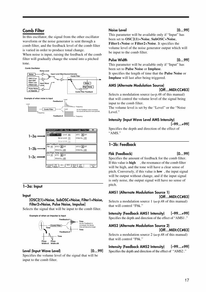
Comb FilterIn this oscillator, the signal from the other oscillatorwaveform or the noise generator is sent through acomb filter, and the feedback level of the comb filteris varied in order to produce tonal change.When noise is input, raising the feedback of the combfilter will gradually change the sound into a pitchedtone.
Frequency
Example of when noise is input
Level
As the Feedback value increases, the sound will become more pitched.
Delay
Comb Filter Feedback
Comb Filter
High Damp
Noise Level
Input Wave Level
Noise
Pulse Noiseor Impulse
Comb Oscillator
Comb Filter
Feedback=0
Feedback>0
Input Level Mod.Source/Intensity
OSC1/2 orSub OSCFilter1 outFilter2 out
Level
Level
Frequency
Frequency
1–3a
1–3b
1–3c
1–3a: Input
Input[OSC2(1)+Noise, SubOSC+Noise, Filter1+Noise,Filter2+Noise, Pulse Noise, Impulse]
Selects the signal that will be input to the comb filter.
Example of when an Impulse is input
As the Feedback is increased, the decay time will become longer.
Time
Time
Comb Filter
PluseWidth=0
PluseWidth=99
Feedback=0
Feedback>0
Time
Time
Level (Input Wave Level) [0…99]Specifies the volume level of the signal that will beinput to the comb filter.
Noise Level [0…99]This parameter will be available only if “Input” hasbeen set to OSC2(1)+Noise, SubOSC+Noise,Filter1+Noise or Filter2+Noise. It specifies thevolume level of the noise generator output which willbe input to the comb filter.
Pulse Width [0…99]This parameter will be available only if “Input” hasbeen set to Pulse Noise or Impluse.It specifies the length of time that the Pulse Noise orImpluse will last after being triggered.
AMS (Alternate Modulation Source)[Off…MIDI:CC#83]
Selects a modulation source (�p.48 of this manual)that will control the volume level of the signal beinginput to the comb filter.The volume level is set by the “Level” or the “NoiseLevel.”
Intensity (Input Wave Level AMS Intensity)[–99…+99]
Specifies the depth and direction of the effect of“AMS.”
1–3b: Feedback
Fbk (Feedback) [0…99]Specifies the amount of feedback for the comb filter.If this value is high , the resonance of the comb filterwill be high, and the tone will have a clear sense ofpitch. Conversely, if this value is low , the input signalwill be output without change, and if the input signalis only noise, the output signal will have no sense ofpitch.
AMS1 (Alternate Modulation Source 1)[Off…MIDI:CC#83]
Selects a modulation source 1 (�p.48 of this manual)that will control “Fbk.”
Intensity (Feedback AMS1 Intensity) [–99…+99]Specifies the depth and direction of the effect of “AMS1 .”
AMS2 (Alternate Modulation Source 2)[Off…MIDI:CC#83]
Selects a modulation source 2 (�p.48 of this manual)that will control “Fbk.”
Intensity (Feedback AMS2 Intensity) [–99…+99]Specifies the depth and direction of the effect of “AMS2 .”

18
VPMThe output of a carrier is phase-modulated by amodulator, and output through wave shape processing.By controlling the wave shaping parameters and thefeedback gain, tonal changes that are different thansimple phase modulation can be produced.
Modulator PitchCarrier Pitch(Basic Pitch)
Carrier Level
Output
Wave Shape Parameter
Feedback Gain
Modulator Level
Modulator Carrier Wave Shape
1–3a
1–3b
1–3a: Carrier
Wave [Saw, Square, Triangle, Sine]Selects the carrier waveform.
Level [0…99]Specifies the output level of the carrier. This willdetermine the output level of the VPM oscillator.
AMS1 (Alternate Modulation 1 Source)[Off…MIDI:CC#83]
Selects a modulation source 1 (�p.48 of this manual)that will control “Level.”
Intensity (Level AMS1 Intensity) [–99…+99]Specifies the depth and direction of the effect of “AMS1.”
AMS2 (Alternate Modulation 2 Source)[Off…MIDI:CC#83]
Selects a modulation source 2 (�p.48 of this manual)that will control “Level.”
Intensity (Level AMS2 Intensity) [–99…+99]Specifies the depth and direction of the effect of “AMS2.”
Wave Shape [0…99]Specifies the number of cycle of wave shaping.As this value is increased, the number of cycles willincrease, causing more overtones to be added to thehigh-frequency range of the sound.
1–3c: High Damp
H. D (High Damp) [0…99]Specifies the amount of attenuation that will beapplied to the high-frequency component of thefeedback signal within the comb filter.As this value is increased, the tone will become moremellow. Conversely, decreasing this value willproduce a brighter tone.
AMS (Alternate Modulation Source)[Off…MIDI:CC#83]
Selects a modulation source (�p.48 of this manual)that will control “H. D.”
Intensity (High Damp AMS Intensity) [–99…+99]Specify the depth and direction in which “AMS” willaffect high damp.

19
Wave Shape:0 Wave Shape:99
Table valiation
Type (Wave Shap Type) [1, 2]1: The signal after wave shaping will be output
without further change. If “Shape” is set to theminimum value, the phase modulated signal will beoutput essentially without change.
2: A rounded waveform will be obtained regardless ofthe “Shape” value.
AMS1 (Alternate Modulation Source 1)[Off…MIDI:CC#83]
Selects a modulation source 1 (�p.48 of this manual)that will control “Wave Shape” value.
Intensity (Shape AMS1 Intensity) [–99…+99]Specifies the depth and direction of the effect of “AMS1.”
AMS2 (Alternate Modulation Source 2)[Off…MIDI:CC#83]
Selects a modulation source 2 (�p.48 of this manual)that will control “Wave Shape” value.
Intensity (Shape AMS2 Intensity) [–99…+99]Specifies the depth and direction of the effect of “AMS2.”
Feedback [0…99]Specifies the amount of the output after wave shapingthat will be fed back to the carrier.
1–3b: Modulator
Wave[Saw, Square, Triangle, Sine, OSC2(1), Sub OSC,Filter1, Filter2]
Select the waveform of the modulator.This selects the other oscillator or sub oscillator etc.If you set this to OSC2(1) , SubOSC , Filter 1 , orFilter 2 , the Frequency Coarse and followingsettings will not be available.
Level [0…99]Specifies the output level of the modulator.This value will determine the amount of modulationthat is applied to the “1–3a: Carrier” setting.
AMS1 (Alternate Modulation Source 1)[Off…MIDI:CC#83]
Selects a modulation source 1 (�p.48 of this manual)that will control “Level.”
Intensity (Level AMS1 Intensity) [–99…+99]Specifies the depth and direction of the effect of“AMS1.”
AMS2 (Alternate Modulation Source 2)[Off…MIDI:CC#83]
Selects a modulation source 2 (�p.48 of this manual)that will control “Level.”
Intensity (Level AMS2 Intensity) [–99…+99]Specifies the depth and direction of the effect of“AMS2.”
Frequency Coarse [0.5, 1…16]Specifies a multiplication factor which will be appliedto the pitch of the modulator, relative to the “1–3a:Carrier” setting.
Fine [–50…+50]Makes fine adjustments to the pitch of the modulator.
AMS1 (Alternate Modulation Source 1)[Off…MIDI:CC#83]
Selects a modulation source 1 (�p.48 of this manual)that will control the pitch of the modulator.
Intensity (Frequncy AMS1 Intensity) [–99…+99]Specifies the depth and direction of the effect of“AMS1.”
AMS2 (Alternate Modulation Source 2)[Off…MIDI:CC#83]
Selects a modulation source 2 (�p.48 of this manual)that will control the pitch of the modulator.
Intensity (Frequncy AMS2 Intensity) [–99…+99]Specifies the depth and direction of the effect of“AMS2.”

20
ResonanceThis oscillator produces a wide range of tonal changeby allowing you to specify the cutoff frequency andresonance of four band pass filters (BPF ).You can select one of the following sources to be theinput for the filters: the output of the other oscillator,the sub-oscillator, the output of the noise generator, orthe output of filter 1 or filter 2.
OSC 1/2
Sub OSC
Noise Generator
BPF2BPF3
BPF4
BPF1
Resonance1 Coarse1
Level1Input Level
Input Select
Filter1 out
Filter2 out
1–3a
1–3b
1–3c
1–3a: Input
Input [OSC 2(1), Sub OSC, Noise, Filter1, Filter2]Selects the signal that will be input to the four bandbass filters.
If you select Resonance for OSC 1 and 2 in“1–2a: Multi Oscillator Synthesis Setup,” andselect the other oscillator as the input for each,the result will be unstable — the sound may benon-reproduceable, or you may hear no soundat all.
Level [0…99]Specifies the level of the signal that is input to thefour band pass filters.
AMS1 (Alternate Modulation Source 1)[Off…MIDI:CC#83]
Selects a modulation source 1 (�p.48 of this manual)that will control “Level.”
Intensity (Level AMS1 Intensity) [–99…+99]Specifies the depth and direction of the effect of“AMS1.”
AMS2 (Alternate Modulation Source 2)[Off…MIDI:CC#83]
Selects a modulation source 2 (�p.48 of this manual)that will control “Level.”
Intensity (Level AMS2 Intensity) [–99…+99]Specifies the depth and direction of the effect of“AMS2.”
1–3b: BPF ParametersHere, you can make settings for each band pass filter 1–4.
Level [0…99]Specifies the output level.
Coarse [1…16]Specifies the harmonic (overtone) of the oscillatorpitch at which the center frequency of the filter will belocated. You can specify from the first to the 16thharmonic.
AMS (Alternate Modulation Source)[Off…MIDI:CC#83]
Selects a modulation source (�p.48 of this manual)that will control “Coarse.”
Int (BPF Frequency AMS Intensity) [–15…+15]Specifies the depth and direction of the effect ofAMS. Positive (+) settings will allow the Coarsevalue to be increased, and negative (–) settings willallow the Coarse value to be decreased. At this time,the center frequency of band pass filter 1 will changein steps of harmonics, creating the impression that thepitch is changing step-wise.
Fine [–99…+99]Makes fine adjustments to the center frequency ofband pass filter 1 specified by the Coarse parameter.
Reso (Resonance) [0…99]Specifies the resonance. Increasing this value willproduce a stronger effect.
1–3c: Resonance Modulation
AMS (Alternate Modulation Source)[Off…MIDI:CC#83]
Selects a modulation source (�p.48 of this manual)that will control the resonance that was specified foreach band pass filter.
Intensity (Resonance AMS Intensity) [–99…+99]Specifies the depth and direction of the effect of“AMS.”

21
Ring ModulationThis multiplies the modulator and carrier and outputsthe signal produced. One of four types of waveformcan be selected as the carrier.Since the result will be a metallic sound with littlesense of pitch, this is suitable for producing soundeffects. The Ring Modulation oscillator contains aninternal carrier oscillator. The output of the otheroscillator etc. can be selected as the modulator.By modifying the pitch of the oscillator, you canproduce characteristic ring modulation effects.
1–3a
1–3b
1–3a: Wave
Input [OSC 2(1), Sub OSC, Noise, Filter1, Filter2]Specifies the modulator.
If Ring Modulation is selected for both OSC 1and 2, and the input of the other is selected foreach, some parameter settings may produce nosound.
Carrier [Saw, Square, Triangle, Sine]Specifies the carrier waveform.
Wave Edge [0…99]Specifies the amount of high frequency harmonics forthe carrier waveform. As this value is decreased, thesound will have less high-frequency harmonics, and asit approaches 0 the volume will also decrease.
Type [1, 2]Selects the modulation type. The two types differ inthe tone of the high range. Type 2 will produce abrighter sound than type 1.
1–3b: Modulation Depth
Depth [0…99]Specifies the depth of modulation. At a setting of 0,the carrier waveform will be output without change.
AMS1 (Alternate Modulation Source 1)[Off…MIDI:CC#83]
Selects a modulation source 1 (�p.48 of this manual)that will control “Depth.”
Intensity (Modulation Depth AMS1 Intensity)[–99…+99]
Specifies the depth and direction of the effect of“AMS1.”
AMS2 (Alternate Modulation Source 2)[Off…MIDI:CC#83]
Selects a modulation source 2 (�p.48 of this manual)that will control “Depth.”
Intensity (Modulation Depth AMS2 Intensity)[–99…+99]
Specifies the depth and direction of the effect of“AMS2.”

22
Cross ModulationThis uses a modulator to frequency-modulate a carrier.You can select one of four waveforms as the carrier.In general, a pitch envelope is applied to the modula-tor. A carrier oscillator is built-in to the CrossModulation OSC. You can select the output of theother oscillator etc. as the modulator.By modifying the pitch of the modulator oscillator,you can produce characteristic cross-modulationeffects.
1–3a
1–3b
1–3a: Wave
Input [OSC2(1), Sub OSC, Noise, Filter1, Filter2]Specifies the modulator.
Carrier [Saw, Square, Triangle, Sine]Specifies the carrier waveform.
Wave Edge [0…99]Specifies the amount of high frequency harmonics forthe carrier waveform. As this value is decreased, thesound will have less high-frequency harmonics, and asit approaches 0 the volume will also decrease.
1–3b: Modulation Depth
Depth [0…99]Specifies the depth of modulation. At a setting of 0,the carrier waveform will be output without change.
AMS1 (Alternate Modulation Source 1)[Off…MIDI:CC#83]
Selects a modulation source 1 (�p.48 of this manual)that will control “ Depth.”
Intensity (Modulation Depth AMS1 Intensity)[–99…+99]
Specifies the depth and direction of the effect of“AMS1.”
AMS2 (Alternate Modulation Source 2)[Off…MIDI:CC#83]
Selects a modulation source 2 (�p.48 of this manual)that will control “Depth.”
Intensity (Modulation Depth AMS2 Intensity)[–99…+99]
Specifies the depth and direction of the effect of“AMS2.”

23
Sync ModulationThis uses the modulator as the master waveform andthe carrier as the slave waveform (which will besynchronized to the master).When the master waveform begins a new cycle (i.e.,the instant that it passes the zero point going fromnegative to positive), the phase of the slave waveformis reset to 0, causing it to begin a new cycle.
Modulator Wave(Master)
Carrier Wave(Slave)
Sync Modulation
1–3a
1–3a: Wave
Input [OSC2(1), Sub OSC, Noise, Filter1, Filter2]Specifies the master waveform (modulator).
Slave [Saw, Square, Triangle, Sine]Specifies the slave waveform.
Wave Edge [0…99]Specifies the amount of high frequency harmonics forthe slave waveform. As this value is decreased, thesound will have less high-frequency harmonics, and asit approaches 0 the volume will also decrease.
Organ ModelThis is an oscillator used to produce organ-typesounds. The oscillator simulates three drawbarssimilar to electric organs of the past.You can specify the footage [Harmo] and waveformsetting for each drawbar, allowing a wide range ofsounds to be created.
Wave
Sine1 or Sine2/Sine3/Triangle
Harmonics(Pitch)
LevelDrawbar1
Drawbar2
Drawbar3
Percussion Level
Precussion
PrecussionDecay/Level Mod.
1–3a
1–3b
1–3a: Tone Generator
Drawbar1:
Wave [Sine 1, Sine 2, Sine 3, Triangle]Specifies the waveform for drawbar 1. Sine 1 containsonly the fundamental (i.e., a pure sine wave). Sine 2and Sine 3 are waveforms which contain the first twoand the first three harmonics respectively.
Coarse (Harmonics Coarse) [1(16’)…16(1’)]Specifies the pitch of drawbar 1, relative to one octavebelow the oscillator pitch.
Fine (Harmonics Coarse Fine) [–99…+99]Makes fine adjustments to the pitch of drawbar 1.
Level [0…99]Specifies the volume level of drawbar 1.
AMS (Alternate Modulation Source)[Off…MIDI:CC#83]
Selects a modulation source (�p.48 of this manual)that will control the “Level” of drawbar 1.

24
Intensity (Level AMS Intensity) [–99…+99]Specifies the depth and direction of the effect of“AMS1.”
Percussion [0…99]Specifies the volume level of the percussion effect fordrawbar 1.
Drawbar 2:Drawbar 3:The parameters are structured identically to those of“1–3a: Drawbar 1.”
Level AMS (Level Alternate Modulation Source)[Off…MIDI:CC#83]
Selects a modulation source (�p.48 of this manual)that will control the percussion level of each drawbar.
Intensity (Level AMS Intensity) [–99…+99]Specifies the depth and direction of the effect of“Level AMS” on the percussion level.
Trigger [Single/Multi]Use the radio buttons to specify how the percussioneffect will be triggered.With a setting of Single, the percussion effect willapply to the first-played note from a condition of nosound.With a setting of Multi, the percussion effect willapply to each note that is played.
Decay [0…99]Specifies the decay length of the percussion. As thisvalue is increased the decay time will become longer.
E. Piano ModelThis oscillator simulates an electric piano.There are four groups of parameters: Hammer (whichspecifies how the shape and motion of the hammerwill affect tonal change and attack noise), ToneGenerator (which vibrates in response to being struckby the hammer), Pickup (which specifies the tonalchange that occurs when the vibration of the tonegenerator is converted into an electrical signal), andLow EQ (which is a shelving-type low EQ to adjustthe low range).
Pickup
Tone Generator
Hammer
Pickup Location
to Low EQ
1–3a
1–3c1–3b
1–3d1–3e
1–3a: Hammer
Force [0…99]Specifies the “Strength” with which the hammerstrikes the tone generator. Higher settings willproduce a brighter sound.
Force Velocity Curve [OFF, 0…99]Specifies how changes in velocity will affect “Force.”As this value is increased, velocity will have agreater effect on “Force,” allowing more dynamictonal change to be produced. With a setting of OFF,the “Force” will be constant.
Width (Hammer Width) [0…99]Simulates the shape of the hammer. As this value isincreased, the width of the hammer will becomenarrower, and the sound of the tone generator andhammer noise will become sharper.
Click Noise Level [0…99]Specifies the volume of the hammer noise that occursat the attack.
25
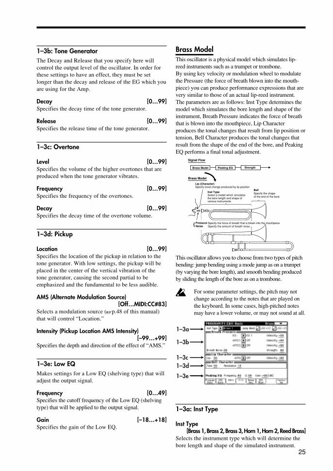
1–3b: Tone GeneratorThe Decay and Release that you specify here willcontrol the output level of the oscillator. In order forthese settings to have an effect, they must be setlonger than the decay and release of the EG which youare using for the Amp.
Decay [0…99]Specifies the decay time of the tone generator.
Release [0…99]Specifies the release time of the tone generator.
1–3c: Overtone
Level [0…99]Specifies the volume of the higher overtones that areproduced when the tone generator vibrates.
Frequency [0…99]Specifies the frequency of the overtones.
Decay [0…99]Specifies the decay time of the overtone volume.
1–3d: Pickup
Location [0…99]Specifies the location of the pickup in relation to thetone generator. With low settings, the pickup will beplaced in the center of the vertical vibration of thetone generator, causing the second partial to beemphasized and the fundamental to be less audible.
AMS (Alternate Modulation Source)[Off…MIDI:CC#83]
Selects a modulation source (�p.48 of this manual)that will control “Location.”
Intensity (Pickup Location AMS Intensity)[–99…+99]
Specifies the depth and direction of the effect of “AMS.”
1–3e: Low EQMakes settings for a Low EQ (shelving type) that willadjust the output signal.
Frequency [0…49]Specifies the cutoff frequency of the Low EQ (shelvingtype) that will be applied to the output signal.
Gain [–18…+18]Specifies the gain of the Low EQ.
Brass ModelThis oscillator is a physical model which simulates lip-reed instruments such as a trumpet or trombone.By using key velocity or modulation wheel to modulatethe Pressure (the force of breath blown into the mouth-piece) you can produce performance expressions that arevery similar to those of an actual lip-reed instrument.The parameters are as follows: Inst Type determines themodel which simulates the bore length and shape of theinstrument, Breath Pressure indicates the force of breaththat is blown into the mouthpiece, Lip Characterproduces the tonal changes that result from lip position ortension, Bell Character produces the tonal changes thatresult from the shape of the end of the bore, and PeakingEQ performs a final tonal adjustment.
Lip (Character)Specify tonal change produced by lip position
Inst TypeSelect a model which simulatesthe bore length and shape of various instruments
BellSpecify the shape of the end of the bore
Specify the force of breath that is blown into the mouthpieceSpecify the amount of breath noise
Pressure Noise {
Brass Model
Signal Flow
Brass Model Peaking EQ Strength
This oscillator allows you to choose from two types of pitchbending: jump bending using a mode jump as on a trumpet(by varying the bore length), and smooth bending producedby sliding the length of the bore as on a trombone.
For some parameter settings, the pitch may notchange according to the notes that are played onthe keyboard. In some cases, high-pitched notesmay have a lower volume, or may not sound at all.
1–3a
1–3b
1–3c1–3d
1–3e
1–3a: Inst Type
Inst Type[Brass 1, Brass 2, Brass 3, Horn 1, Horn 2, Reed Brass]
Selects the instrument type which will determine thebore length and shape of the simulated instrument.

26
Jump Bend:
JS(+X) (Joystick +X)Specifies how the pitch will change when the joystick ismoved in the +X direction (toward the right).If this is checked, the pitch will rise by in steps bychanging the resonance of the bore, as on a trumpet.If this is unchecked, the pitch will rise smoothly, ason most synthesizers.
JS(-X) (Joystick -X)Specifies how the pitch will change when the joystick ismoved in the –X direction (toward the left).
If Jump Bend (+X) and Jump Bend (–X) arechecked, notes may not sound depending on theposition of the joystick and the pitch range setting.For details on setting the pitch range of the joystick,refer to “2–4a: Picth Bend.”
1–3b: Breath Pressure
EG [EG 1…EG 4, Amp EG]Selects the EG which will control pressure.For details on the settings for each EG, refer to “Program P6”for EG 1–4, and “4–3: Amp EG” for Amp EG.
Intensity (Pressure EG Intensity) [–99…+99]Specifies the depth and direction of the effect that the“EG” will have on the pressure.
AMS1 (Alternate Modulation Source 1)[Off…MIDI:CC#83]
Selects a modulation source 1 (�p.48 of this manual)that will control pressure. If you select After Touch,pressing down on the keyboard will produce the effectof the instrument being blown strongly. If you selectJoy Stick(X), rotating the Joy Stick in the + directionwill produce this effect. In this case, setting “Intensity(Pressure EG Intensity)” to 0 will allow you tocompletely control the breath pressure by operatingthe specified controller.
Intensity (Pressure AMS1 Intensity) [–99…+99]Specifies the depth and direction of the change inpressure controlled by “AMS1.”
AMS2 (Alternate Modulation Source 2)[Off…MIDI:CC#83]
Selects a modulation source 2 (�p.48 of this manual)that will control pressure.
Intensity (Pressure AMS2 Intensity) [–99…+99]Specifies the depth and direction of the change inpressure controlled by “AMS2.”
Breath Noise [0…99]Specifies the volume level of the breath noise. Since
this uses the signal from the noise generator, the filterof the noise generator can be used to modify the toneof the noise.
Strength [0…99]Adjusts the tone. Higher settings of this value willproduce a overdriven sound.
1–3c: Lip Character
Lip [0…99]Specifies the tonal change that is produced by lipposition and tension. Higher settings of this value willproduce a harder (more firmly blown) sound. Lowersettings will produce a softer tone.
AMS (Alternate Modulation Source)[Off…MIDI:CC#83]
Selects a modulation source (�p.48 of this manual)that will control “Lip.”
Intensity (Lip Character AMS Intensity) [–99…+99]Specifies the depth and direction of the effect of “AMS.”
1–3d: Bell Character
Tone [0…99]Specifies the tone of the bell. As this value is in-creased, the low frequency portion will disappear,producing a less solid tone.
Resonance [0…99]Specifies the level at which the frequency region inthe area of the “Tone” will be boosted. As this valueis increased, the resonance effect will becomestronger.
1–3e: Peaking EQ
Frequency [0…49]Specifies the center frequency of the frequency rangethat will be boosted or attenuated by the Peaking EQ.Increasing this value will raise the center frequency.
Q [0…29]Specifies the width of the Peaking EQ frequencyband. Increasing this value will narrow the frequencyband that is boosted or attenuated.
Gain [–18…+18]Specifies the amount by which the area specified by“Frequency” and “Q” will be boosted or attenuated.

27
Reed ModelThis oscillator is a physical model which simulateswoodwind reed instruments such as a saxophone or oboe.By using key velocity or the modulation wheel to controlPressure (the strength with which the reed is blown), youcan use performance expressions that are very close tothose of an actual woodwind instrument. Also, bymodulating the characteristics of the reed, you canproduce tonal changes that correspond with the way inwhich a reed is blown.
Inst TypeSelect a model to specify the bore length and shape of the instrument to be simulated
Reed CharacterSpecify the vibrational characteristics of the reed
Presure Specify the force of the breath that is blown into the reedNoise Specify the amount of breath noise
{
Reed Model Bell Character Wave Shape
Reed Model
Signal Flow
Peaking EQ
1–3a
1–3b
1–3c
1–3e1–3f
1–3d
1–3a: Inst Type
Inst Type [Hard Sax 1...Reed Synth]Selects the type of instrument whose bore shape andreed characteristics will be simulated.
Hard Sax 1, Hard Sax 2, Hard Sax 3, Soft Sax1, Soft Sax 2, Double Reed 1, Double Reed 2,Bassoon, Clarinet, Flute 1, Flute 2, Pan Flute,Ocarina, Shakuhachi, Harmonica 1, Harmonica2, Reed Synth
Jump Bend:JS(+X) (Joystick +X)Specifies how the pitch will change when the joystickis moved in the +X direction (toward the right).If this is checked, the pitch will rise in steps bychanging the resonance of the bore, as on a flute.If this is unchecked, the pitch will rise smoothly, ason most synthesizers.
JS(-X) (Joystick -X)Specifies how the pitch will change when the joystick ismoved in the –X direction (toward the left).
If Jump Bend (+X) and Jump Bend (–X) arechecked, notes may not sound depending onthe position of the joystick and the pitch rangesetting.For details on setting the pitch range of thejoystick, refer to “1–2c: Pich Bend.”
1–3b: Breath Pressure
EG [EG 1…EG 4, AmpEG]Selects the EG which will control pressure.For details on the settings for each EG, refer to“Program P6” for EG 1–4, and “4–3: Amp EG” forAmp EG.
Intensity (Pressure EG Intensity) [–99…+99]Specifies the depth and direction of the effect that theEG will have on the pressure.
AMS1 (Alternate Modulation Source 1)[Off…MIDI:CC#83]
Selects a modulation source 1 (�p.48 of this manual)that will control pressure. If you select After Touch,pressing down on the keyboard will produce the effectof the instrument being blown strongly. If you selectJoy Stick (X), moving the joy stick toward the rightwill produce this effect.
Intensity (Pressure AMS1 Intensity) [–99…+99]Specifies the depth and direction of the change inpressure controlled by AMS1.
AMS2 (Alternate Modulation Source 2)[Off…MIDI:CC#83]
Selects a modulation source 2 (�p.48 of this manual)that will control pressure.
Intensity (Pressure AMS2 Intensity) [–99…+99]Specifies the depth and direction of the change inpressure controlled by AMS2.
Breath Noise [0…99]Specifies the volume level of the breath noise.Since this uses the signal from the noise generator, thefilter of the noise generator can be used to modify thetone of the noise.
28
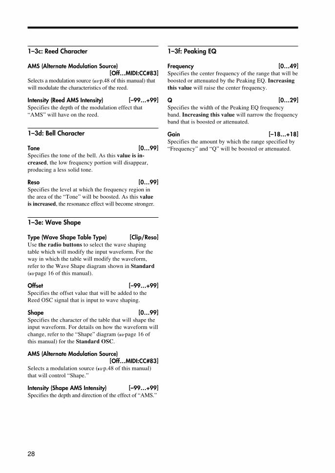
1–3c: Reed Character
AMS (Alternate Modulation Source)[Off…MIDI:CC#83]
Selects a modulation source (�p.48 of this manual) thatwill modulate the characteristics of the reed.
Intensity (Reed AMS Intensity) [–99…+99]Specifies the depth of the modulation effect that“AMS” will have on the reed.
1–3d: Bell Character
Tone [0…99]Specifies the tone of the bell. As this value is in-creased, the low frequency portion will disappear,producing a less solid tone.
Reso [0…99]Specifies the level at which the frequency region inthe area of the “Tone” will be boosted. As this valueis increased, the resonance effect will become stronger.
1–3e: Wave Shape
Type (Wave Shape Table Type) [Clip/Reso]Use the radio buttons to select the wave shapingtable which will modify the input waveform. For theway in which the table will modify the waveform,refer to the Wave Shape diagram shown in Standard(�page 16 of this manual).
Offset [–99…+99]Specifies the offset value that will be added to theReed OSC signal that is input to wave shaping.
Shape [0…99]Specifies the character of the table that will shape theinput waveform. For details on how the waveform willchange, refer to the “Shape” diagram (�page 16 ofthis manual) for the Standard OSC.
AMS (Alternate Modulation Source)[Off…MIDI:CC#83]
Selects a modulation source (�p.48 of this manual)that will control “Shape.”
Intensity (Shape AMS Intensity) [–99…+99]Specifies the depth and direction of the effect of “AMS.”
1–3f: Peaking EQ
Frequency [0…49]Specifies the center frequency of the range that will beboosted or attenuated by the Peaking EQ. Increasingthis value will raise the center frequency.
Q [0…29]Specifies the width of the Peaking EQ frequencyband. Increasing this value will narrow the frequencyband that is boosted or attenuated.
Gain [–18…+18]Specifies the amount by which the range specified by“Frequency” and “Q” will be boosted or attenuated.

29
Plucked String ModelThis oscillator is a physical model which simulatesplucked string instruments such as a guitar or bassguitar. You can specify aspects of the model such asthe attack waveform that is produced when the stringis plucked by a pick or finger, the characteristics ofthe string, the location of the pickup, etc.
Attack Level Specify the strength of playing (the level of the attack waveform).Noise Specify the level and tone of the noise included in the attack waveform.Attack Curve Specify the envelope of the attack waveform.
Parameters relating to the attack waveform
Delay/ReleaseSpecify the ratio of the wave transmitted along the string which is reflected back from the bridge (decay/release time).
Bridge Bridge
String PositionSpecify the location at which the string is struck.
Parameters relating to the characteristics of the stringDamping Specify the high frequency attenuation of the wave transmitted along the string. To simulate muted playing techniques, control this parameter.Dispersion Specify tonal change caused by inharmonicity of the higher partials
Harmonics Position Specify the string location to be pressed to play harmonicsHarmonics Mod.Source / Mod.Int. Specify the controller which will control the harmonics effect, and the depth of control.
String Model
String Model Pickup Low EQ & Low Boost
Signal Flow
1–3a
1–3c
1–3b
1–3d1–3e1–3f
1–3a: Attack
Attack Level [0…99]Specifies the force with which the string is plucked.
Velocity (Attack Level Velocity Control) [–99…+99]Specifies the depth and direction of the effect thatvelocity will have on “Attack Level.” The effect willbe as shown in the following diagram.
Parameter value
Velocity value1 127
+ –
+99 –99
0
Noise Level [0…99]Specifies the level of the noise component that isincluded in the attack waveform. As this value isincreased, a greater portion of noise will be includedin the attack, and the sound will be brighter with moreovertones. The noise signal used here is taken fromthe output of the noise generator.
Velocity (Noise Level Velocity Control)[–99…+99]
Specifies the depth and direction of the effect thatvelocity will have on Noise Level. For the way inwhich the effect occurs, refer to “Velocity (AttackLevel Velosity Control).”
1–3b: Attack Curve
Up (Curre Up) [0…99]Specifies the steepness of the rising edge of the attackwaveform.When the rising or falling edge is steep, thetone will be harder.
Envelope of the attack waveformVolume level
Curve Up Curve Down
Velocity (Curve Up Velocity Control) [–99…+99]Specifies the depth and direction of the effect thatvelocity will have on “Up.” For the way in which theeffect occurs, refer to “Velocity (Attack Level VelosityControl).”
Down (Curre Down) [0…99]Specifies the steepness of the falling edge of the attackwaveform.
Velocity (Curve Down Velocity Control)[–99…+99]
Specifies the depth and direction of the effect thatvelocity will have on “Curve Down.” For the way inwhich the effect occurs, refer to “Velocity (AttackLevel Velosity Control).”
1–3c: String
Picking Point [0…99]Specifies the location at which the string will beplucked. A setting of 0 is the end of the string, 50 isthe middle of the string, and 99 is the other end of thestring.

30
AMS (Alternate Modulation Source)[Off…MIDI:CC#83]
Selects a modulation source (�p.48 of this manual)that will control “Picking Point.”
Intensity (Picking Point AMS Intensity)[–99…+99]
Specifies the depth and direction of the effect of“AMS.”
Damp [0…99]Specifies the amount of high-frequency attenuationthat will be produced by the characteristics of thestring and by how the string is pressed.As this value is increased, the high-frequencycomponents of the vibration in the string will beattenuated (dampened) more strongly, producing adarker sound. In general, this parameter should be setto a higher value to simulate instruments which usesoft strings or which have no frets, and to a lowervalue to simulate instruments which use hard stringsor which have frets.
KTr (Damp Keyboard Track) [–99…+99]Specifies how the Damp amount will be affected bythe keyboard location.With positive (+) settings, the Damp value willincrease as you play notes above C4.With negative (–) settings, the Damp will decrease asyou play notes above C4.
when Damp=50 when Damp=75when Damp=25C-1 C4 C9
99
0
50
C-1 C4 C9
99
0
75
C-1 C4 C9
99
0
25
+99 +50
0
-99 -50
+99 +50
0
-50-99
+99
+50
-50-99
0
Damp DampDamp
AMS (Alternate Modulation Source)[Off…MIDI:CC#83]
Selects a modulation source (�p.48 of this manual)that will control “Damp.”
Intensity (Damp AMS Intensity) [–99…+99]Specifies the depth and direction of the effect that“AMS” will have.
Decay [0…99]Specifies the decay time over which the sound willdecay if you continue pressing a note. Higher settingsof this value will produce a longer decay time.
Depending on the settings of “4–3: Amp EG”,the setting you make here may not haveaudible results. If you raise the EG break leveland sustain level, it will be easier to hear theresult of this setting.
KTr (Decay Keyboard Track) [–99…+99]Specifies how the “Decay” amount will be affected bythe keyboard location.With positive (+) settings, the decay will becomefaster as you play notes above C4. With negative (–)settings, it will become slower.
when Decay=50 when Decay=75when Decay=25C-1 C4 C9
99
0
50
C-1 C4 C9
99
0
75
C-1 C4 C9
99
0
25
+99 +50
0
-99 -50
+99 +50
0
-50-99
+99
+50
-50-99
0
Decay DecayDecay
Release [0…99]Specifies the length of time over which the sound willdecay after you release the note. Higher settings ofthis value will produce a longer release time.
Depending on the settings of “4–3: Amp EG”,the setting you make here may not haveaudible results. You may need to raise the EGrelease level, it will be easier to hear the resultof this setting.
Dispersion [0…99]Specifies the inharmonicity of the higher partialsrelative to the fundamental. With a value of 0, thepartials will be located at integer (whole number)multiples of the fundamental. As this value isincreased, the partials will move further away frominteger multiple locations. In general, thin and flexiblestrings can be simulated by a low “Dispersion” value,and thick and stiff strings can be simulated by a high“Dispersion” value.
If this value is raised excessively, the pitchmay become unstable.
AMS (Alternate Modulation Source)[Off…MIDI:CC#83]
Selects a modulation source (�p.48 of this manual)that will control “Dispersion.”
Intensity (Dispersion AMS Intensity) [–99…+99]Specifies the depth and direction of the effect of“AMS.”
1–3d: Harmonics
Point [0…99]Specifies the location at which the string will bepressed to play harmonics.

31
Ctrl (Control) [Off…MIDI:CC#83]Selects a modulation source (�p.48 of this manual)that will control the harmonics effect.
Intensity (Harmonics Control Intensity) [–99…+99]Specifies the depth and direction of the control that“Ctrl” will have on the harmonics effect.
When making the Position setting, you mustassign Control to a controller other than OFF,and raise the Intensity value. The decay timeof the harmonics effect will differ dependingon the keyboard location that you play.
1–3e: Pickup
PickupIf this is checked, the sound will be passed through asimulated pickup. If this is not checked, the soundwill remain unchanged.
Location, AMS, and Intensity can be set whenPickup has been checked.
Location [0…99]Adjusts the change in tone that results from differ-ences in pickup location.
AMS (Alternate Modulation Source)[Off…MIDI:CC#83]
Selects a modulation source (�p.48 of this manual)that will control “Pickup.”
Intensity (Pickup Location AMS Intensity)[–99…+99]
Specifies the depth and direction of the effect of“AMS.”
1–3f: Low EQ
Frequency [0…49]Specifies the cutoff frequency of the Low EQ.
Gain [–18…+18]Specifies the gain of the Low EQ.
Low Boost [0…99]Specifies how the low frequency range will beemphasized. Raising this value will cause the lowfrequency range to be emphasized more strongly.
Bowed String ModelThis oscillator is a physical model which simulates thesound of a bowed string instrument such as a violin orcello. By controlling the bowing speed and the bowingpressure, you can create performance expressions thatare very close to those of an actual bowed stringinstrument.
Parameters related to the stringString DampDispersion
String vibration
String
Bow
Position
Bow Speed
Pressure
Bridge Reflection
Bridge Reflection
Bowed String Model
Bowed String Model Peaking EQ
1–3b
1–3a
1–3c
1–3d
1–3a: Bow Speed
EG [EG 1…EG 4, AmpEG]Selects the EG which will control bowing speed (thespeed at which the bow moves across the string).
Int (Speed Modulation EG Intensity) [–99…+99]Specifies the depth and direction of the effect of “EG”With negative (–) settings, the direction of the bowspeed will be inverted.
AMS1 (Alternate Modulation Source 1)[Off…MIDI:CC#83]
Selects a modulation source 1 (�p.48 of this manual)that will control bowing speed.Instead of using an EG to modify the bowing speed,you can use the Ribbon Controller or Joy Stick tosimulate bowing without using an EG.
Int (Speed AMS1 Intensity) [–99…+99]Specifies the depth and direction of the effect of“AMS1.”
AMS2 (Alternate Modulation Source 2)[Off…MIDI:CC#83]
Selects a modulation source 2 (�p.48 of this manual)that will control bowing speed.

32
Int (Speed AMS2 Intensity) [–99…+99]Specifies the depth and direction of the effect of“AMS2.”
DifferentialIf this is not checked, the value produced by EG,AMS1 and AMS2 will be used as the bowing speed. Ifyou wish to use EG to control the bowing speed, leavethis item un-checked.If this is checked, the rate of change of EG, AMS1 andAMS2 will be used as the bowing speed.• Using the ribbon controller to control bowing speedAs an example, we will assume that you have setAMS1 to Ribbon (X). In order to control bowingspeed using the ribbon controller alone, raise the Int.(Speed AMS1 Intensity) value, and set Int. (SpeedModulation EG Intensity) to 0. Check Differential.When you are pressing the ribbon controller, thebowing speed will be zero, so there will be no sound.As you slide your finger toward the right over theribbon controller, the speed at which your fingermoves will be the bowing speed, and sound will beproduced. As you slide your finger to left and right,the bowing speed will change from positive �zero�
negative� zero�positive, allowing you to produceperformance expressions that are very similar to thoseof actually moving a bow back and forth.
Rosin [0…99]Specifies the coefficient of static friction between thebow and the string. (This corresponds to the amount ofrosin on the bow.)Higher values will increase the friction between thebow and string. When this value is in the region of 0,it will be difficult for playing strength to be transmit-ted to the string.
1–3b: Bow Pressure
EG [EG 1…EG 4, AmpEG]Selects the EG which will control the pressure of thebow on the string (bow pressure).
Int (Pressure EG Intensity) [–99…+99]Specifies the depth and direction of the effect that the“EG” will have on bow pressure.If this value is low, the bow will rest lightly on thestring.
AMS (Alternate Modulation Source)[Off…MIDI:CC#83]
Selects a modulation source (�p.48 of this manual)that will control bow pressure.
Int (Pressure AMS Intensity) [–99…+99]Specifies the depth of the effect produced by “AMS.”
1–3c: String
Bowing Point [0…99]Specifies the location at which the bow contacts thestring. A setting of 0 is the end of the string, 50 is nearthe middle, and 99 is at the other end.
AMS (Alternate Modulation Source)[Off…MIDI:CC#83]
Selects a modulation source (�p.48 of this manual)that will control “Bowing Point.”Changing the location at which the string is bowedwill also change the overtone structure.
Intensity (Bowing Point AMS Intensity)[–99…+99]
Specifies the depth and direction of the effect of“AMS.”
Damp [0…99]Specifies how the high frequency components will beattenuated by the characteristics of the string and bythe way in which the string is pressed onto thefingerboard of the violin or cello.As this value is increased, the high frequencycomponents of the wave transmitted along the stringwill be attenuated more greatly, producing a darkersound. In general, you should use higher values tosimulate instruments which have flexible strings orunfretted instruments, and lower values to simulateinstruments with stiff strings or fretted instruments.
AMS (Alternate Modulation Source)[Off…MIDI:CC#83]
Selects a modulation source (�p.48 of this manual)that will control “Damp.”
Intensity (Damp AMS Intensity) [–99…+99]Specifies the depth and direction of the effect of“AMS.”
Damp KTr Key (Damp Keyboard Track Key)[C–1…G9]
Specifies the key above and below which keyboardtracking will begin to apply to the “Damp” effect.
You can also input a value by playing a noteon the keyboard while you hold down the[ENTER] key.
Ramp Low [–99…+99]Specifies the depth and direction in which the “Damp”amount will change for notes below the “Damp KTrKey.” Positive (+) settings will cause “Damp” toincrease for notes below the “Damp KTr Key.”Negative (–) settings will cause “Damp” to decreasefor notes below the “Damp KTr Key.”

33
Ramp High [–99…+99]Specifies the depth and direction in which the “Damp”amount will change for notes above the “Damp KTrKey.” Positive (+) settings will cause “Damp” toincrease for notes above the “Damp KTr Key.”Negative (–) settings will cause “Damping” todecrease for notes above the “Damping KTr Key.”
Dispersion [0…99]Specifies the inharmonicity of the higher partialsrelative to the fundamental. With a value of 0, thepartials will be located at integer (whole number)xmultiples of the fundamental. As this value is in-creased, the partials will move further away frominteger multiple locations. In general, thin and flexiblestrings can be simulated by a low “Dispersion” value,and thick and stiff strings can be simulated by a high“Dispersion” value.
If this value is raised excessively, the pitchmay become unstable.
AMS (Alternate Modulation Source)[Off…MIDI:CC#83]
Selects a modulation source (�p.48 of this manual)that will control “Dispersion.”
Intensity (Dispersion AMS Intensity) [–99…+99]Specifies the depth and direction of the effect of “AMS.”
Bridge Reflection [0…99]Specifies the amount of the wave that will be reflectedat the end of the string. Higher values will make thenotes sound more easily. With a setting of 0 there willbe no reflection at all.
AMS (Alternate Modulation Source)[Off…MIDI:CC#83]
Selects a modulation source (�p.48 of this manual)that will control “Bridge Reflection.”
Intensity (Bridge Reflection AMS Intensity)[–99…+99]
Specifies the depth and direction of the effect of “AMS.”
1–3d: Peaking EQ
Frequency [0…49]Specifies the center frequency at which the peakingEQ will boost (attenuate) the sound.
Q [0…29]Specifies the width of the region that will be boosted(attenuated) by the peaking EQ. With a setting of 0, awide region will be affected. With a setting of 29,only a narrow region close to the center frequency willbe boosted (attenuated).
Gain [–18…+18]Specifies the gain by which the peaking EQ will boostor attenuate.
1–4: OSC2 (Oscillator 2)OSC2 parameters have the same structure as OSC1parameters. Refer to “1–3: OSC 1.”
1–5: Noise GeneratorMake settings for the noise generator.The noise generator produces white noise. The noisesignal is passed through a dedicated filter, and is thenmixed with the oscillator 1, 2, and sub oscillator signalsby the mixer section. (Refer to 1–6: OSC Mixer.)
Noise Generator
Cutoff Frequency Resonance
Low Pass
High Pass
Band Pass
Thru
Filter TypeInput Trim
Noise Filter
1–5a
1–5b
1–5a: Noise Generator
Filter Type [Thru, Low Pass, High Pass, Band Pass]Selects the type of filter that will be applied to theoutput of the noise generator.If Thru is selected, the parameter settings describedbelow will not be available.
Input Trim [0…99]Specifies the input level to the dedicated noise filter.
Frequency (Cutoff Frequency) [0…99]Specifies the cutoff frequency of the noise signalfilter. For the characteristics of each filter type, referto “3–1:Filter1” (�page 38 of this manual).
Resonance [0…99]This boosts the frequency region specified by the“Cutoff Frequency” to add character to the sound.
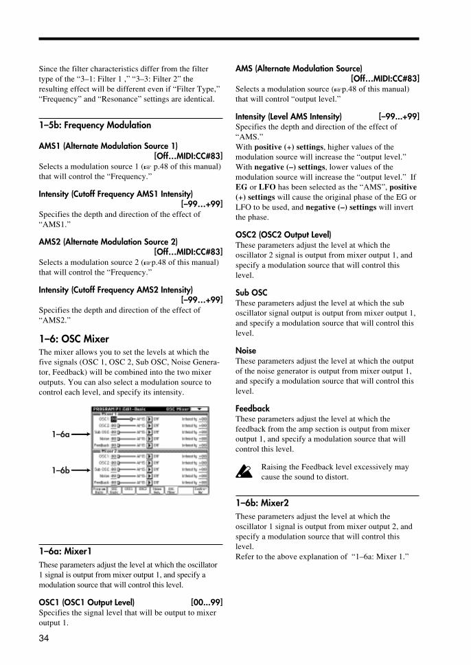
34
Since the filter characteristics differ from the filtertype of the “3–1: Filter 1 ,” “3–3: Filter 2” theresulting effect will be different even if “Filter Type,”“Frequency” and “Resonance” settings are identical.
1–5b: Frequency Modulation
AMS1 (Alternate Modulation Source 1)[Off…MIDI:CC#83]
Selects a modulation source 1 (� p.48 of this manual)that will control the “Frequency.”
Intensity (Cutoff Frequency AMS1 Intensity)[–99…+99]
Specifies the depth and direction of the effect of“AMS1.”
AMS2 (Alternate Modulation Source 2)[Off…MIDI:CC#83]
Selects a modulation source 2 (�p.48 of this manual)that will control the “Frequency.”
Intensity (Cutoff Frequency AMS2 Intensity)[–99…+99]
Specifies the depth and direction of the effect of“AMS2.”
1–6: OSC MixerThe mixer allows you to set the levels at which thefive signals (OSC 1, OSC 2, Sub OSC, Noise Genera-tor, Feedback) will be combined into the two mixeroutputs. You can also select a modulation source tocontrol each level, and specify its intensity.
1–6a
1–6b
1–6a: Mixer1These parameters adjust the level at which the oscillator1 signal is output from mixer output 1, and specify amodulation source that will control this level.
OSC1 (OSC1 Output Level) [00...99]Specifies the signal level that will be output to mixeroutput 1.
AMS (Alternate Modulation Source)[Off…MIDI:CC#83]
Selects a modulation source (�p.48 of this manual)that will control “output level.”
Intensity (Level AMS Intensity) [–99...+99]Specifies the depth and direction of the effect of“AMS.”With positive (+) settings, higher values of themodulation source will increase the “output level.”With negative (–) settings, lower values of themodulation source will increase the “output level.” IfEG or LFO has been selected as the “AMS”, positive(+) settings will cause the original phase of the EG orLFO to be used, and negative (–) settings will invertthe phase.
OSC2 (OSC2 Output Level)These parameters adjust the level at which theoscillator 2 signal is output from mixer output 1, andspecify a modulation source that will control thislevel.
Sub OSCThese parameters adjust the level at which the suboscillator signal output is output from mixer output 1,and specify a modulation source that will control thislevel.
NoiseThese parameters adjust the level at which the outputof the noise generator is output from mixer output 1,and specify a modulation source that will control thislevel.
FeedbackThese parameters adjust the level at which thefeedback from the amp section is output from mixeroutput 1, and specify a modulation source that willcontrol this level.
Raising the Feedback level excessively maycause the sound to distort.
1–6b: Mixer2These parameters adjust the level at which theoscillator 1 signal is output from mixer output 2, andspecify a modulation source that will control thislevel.Refer to the above explanation of “1–6a: Mixer 1.”

35
1–7: Contoller Setup
1–7a
1–7b
1-7a: Panel Switch AssignAssign the function of the front panel [SW1] and[SW2] keys.�Refer to TRITON Parameter Guide p.217 “SW1,SW2 Assign List.”Since the [SW1] and [SW2] settings of the programassigned to each timbre are not used by a combination,they must be set here again.� Refer to TRITON Parameter Guide p.8 “PanelSwitch Assign” (Program P1: 1–4a).
SW1 (SW1 Assign) [Off, ..., After Touch Lock]
SW1 Mode [Toggle, Momentary]
SW2 (SW2 Assign) [Off, ..., After Touch Lock]
SW2 Mode [Toggle, Momentary]
1-7b: Realtime Contol Knobs B-AssignHere you can assign the B-mode functions (mainlyvarious types of control change) for the front panelREALTIME CONTROLS [1]–[4] knobs. Thefunctions you select here will operate when you movethe corresponding knob of the REALTIME CON-TROLS [1]–[4] knobs when B-mode is selected.� Refer to TRITON Parameter Guide p.218“Realtime Control Knobs B-Assign List.”
Knob 1-B [Off, ..., MIDI CC #00...CC #95]
Knob 2-B [Off, ..., MIDI CC #00...CC #95]
Knob 3-B [Off, ..., MIDI CC #00...CC #95]
Knob 4-B [Off, ..., MIDI CC #00...CC #95]

36
Program P2: Edit-Pitch
2-1: OSC1 P. Mod(Oscillator 1 Pitch Modulation)
2–1a
2–1b
2–1a: Pitch SlopeSpecifies how pitch will change in relation to thekeyboard (key.)
Center Key [C–1…G9]Specifies the key at which Lower/Higher keyboardtracking will begin to apply.
You can also input a value by playing a noteon the keyboard while you hold down the[ENTER] key.
Ramp Low [–1.00…+2.00]Specifies the depth and direction of the pitch changethat will occur for notes below the “Center Key.”
Ramp High [–1.00…+2.00]Specifies the depth and direction of the pitch changethat will occur for notes above the Center Key.When Low Slope and High Slope are set to +2.0,playing one octave upward from the Center Key willcause the pitch to rise two octaves.With a setting of –1.0, playing one octave upward willcause the pitch to fall one octave. With a setting of0.0, the notes in the respective areas will produce thesame pitch as the Center Key. To play pitchesnormally, set this parameter to +1.0.
C-1 C4 C9C-1
C9
Pitch
Key
Center Key
1.0+2.0 +1.0
0.0
2–1b: Pitch ModulationSpecifies the pitch Modulation.
AMS1 (Alternate Modulation Source 1)[Off…MIDI:CC#83]
Selects a modulation source 1 (�p.48 of this manual)which will modify the pitch (e.g., apply vibrato).
Intensity (Pitch AMS1 Intensity) [–99…+99]Specifies the depth and direction of the pitch changethat will be controlled by “AMS1.”
AMS(AMS1 Intensity Alternate Modulation Source)[Off…MIDI:CC#83]
Specifies the controller (�p.48 of this manual) thatwill control the “Intensity (Pitch AMS1 Intensity).”
Intensity (AMS1 Int AMS Intensity)[–99…+99]
Specifies the depth of the pitch modulation effectcontrolled by “AMS1.”
AMS2 (Alternate Modulation Source 2)[Off…MIDI:CC#83]
Selects a modulation source 2 (�p.48 of this manual)which will modify the pitch (e.g., apply vibrato).
Intensity (Pitch AMS2 Intensity) [–99…+99]Specifies the depth of the pitch modulation effectcontrolled by “AMS2.”
2–2: OSC2 P.Mod(Oscillator 2 Pitch Modulation)
2–3: SubOSC P.Mod(Sub Oscillator Pitch Modulation)
OSC2 P.Mod and SubOSC P.Mod, have the sameparameter as OSC 1. Refer to “2–1: OSC1 P. Mod”
2–4: Common P.Mod
2–4a
2–4b
2–4c

37
2–4a: Pitch BendSpecifies the width of pitch change that will occurwhen the joystick is moved to left and right.
JS(+X) (Joystick Intensity +X) [–60…+24]Specifies the amount and direction of pitch change (insemitone units) that will occur when the joystick ismoved to the right.With positive (+) settings the pitch will rise, and withnegative (-) settings the pitch will fall. A setting of 12will produce one octave of change.
Step (Joystick Step +X)[Continuous, 1/8, 1/4, 1/2, 1…12]
Specifies how the pitch will change when the joystickis moved to the right.Continuous: Smooth change.
1/8: Change in 1/8 semitone steps.1/4: Change in 1/4 semitone steps.1/2: Change in 1/2 semitone steps.1...12: Change in steps of the specified number ofsemitones (up to 1 octave).
JS(–X) (Joystick Intensity –X) [–60…+24]Specifies the amount and direction of pitch change (insemitone units) that will occur when the joystick ismoved to the left.
Step (Joystick Step –X)[Continuous, 1/8, 1/4, 1/2, 1…12]
Specifies how the pitch will change when the joystickis moved to the left.Refer to Step (Joystick Step +X).
If the Step (Joystick Step +X) or Step (Joy-stick Step –X) settings are greater than thesettings for JS (+X) and JS (–X), the pitch willnot change.
2–4b: Common Pitch ModulationCreates time-varying changes in the pitch of alloscillators (oscillators 1 and 2, and the sub oscillator).
AMS (Alternate Modulation Source)[Off…MIDI:CC#83]
Selects the modulation source (�p.48 of this manual)that will control the pitch of all oscillators (oscillators1 and 2, and the sub oscillator).
Intensity (Common Pitch AMS Intensity)[–99…+99]
Specifies the depth and direction of the effect pro-duced by AMS.
2–4c: PortamentoThese settings specify how portamento will beapplied. (Portamento creates a smooth change in pitchfrom one note to the next.)
EnableCheck this when you wish to use portamento.
FingeredCheck this when you want to apply portamento onlywhen a note is pressed while continuing to hold theprevious note.
Time [0…99]Specifies the portamento time. Higher values willcause the pitch to change more slowly.
AMS (Alternate Modulation Source)[Off…MIDI:CC#83]
Selects a modulation source (�p.48 of this manual)that will control “Time.”
Intensity (Portamento Time AMS Intensity)[–99…+99]
Specifies the dipth and direction in which theportamento time will be controlled by the “AMS .”

38
Program P3: Edit-FilterHere, you can make settings for one of the two multi-mode filters.
3–1: Filter 1Each multi-mode filter can be set to one of five filtertypes.
Multimode Filter
Low PassHigh PassBand PassBand RejectDual BPF
Filter TypeInput TrimCutoff Frequency
Resonance
3–1d
3–1a
3–1c
3–1b
3–1a: Routing (Filter Routing)
Routing [Serial 1/Serial 2/Parallel]Use the radio buttons to select the way in whichfilters 1 and 2 will be combined.
Filter2:Link to Filter 1If this is checked, Filter 2 will be linked to Filter 1,and the following settings will be the same as thesettings of Filter 1.If this is not checked, the following parameters canbe set for Filter 2.
3–1b: Filter Type
Filter Type[Low Pass(A), High Pass(A), Band Pass(A), BandReject(A), Dual BPF(A/B)]
Selects the filter type.When Dual BPF(A/B) is selected, the “3–1d: Filter B”parameters can also be set.
Filter Types and Cutoff FrequencyLow Pass Filter (Low Pass)
Dual Band Pass Filter (Dual BPF)
Cutoff Frequency A
Cutoff Frequency B
A low pass filter is the most commonly-used type of filter, and passes the range of frequencies that lie below the cutoff frequency, and cuts the high range. Cutting the higher partials will cause a bright sound to become darker (more mellow).
A high pass filter passes the range of frequencies that lie above the cutoff frequency, and cuts the low range. This type of filter is used when you wish to make the sound thinner. However, raising the cutoff frequency excessively will drastically reduce the volume.
A band pass filter passes the range of frequencies in the vicinity of the cutoff frequency, and cuts the ranges above and below. This type of filter is used when you wish to emphasize a particular portion of the sound.
The dual band pass filter places two band pass filters in parallel. It allows you to simulate sounds such as human voice and the body resonances of a violin or guitar.
Band Pass Filter (Band Pass)
High Pass Filter (High Pass)
Cutoff Frequency
A band reject filter cuts only the range in the vicinity of the cutoff frequency, and passes the rest of the sound. This type of filter gives a unique character to the sound.
Band Reject Filter (Band Reject)
Cutoff Frequency
Cutoff Frequency
Cutoff Frequency
frequency
frequency
frequency
frequency
frequency
A Trim [0…99]Specifies the level of the input to filter A.
If this value is raised, the sound may becomedistorted if the resonance setting is high, etc.
B Trim [0…99]Specifies the level of the input to filter B.
If this value is raised, the sound may becomedistorted if the resonance setting is high, etc.
3–1c: Filter A
Frequency (Cutoff Frequency) [0…99]Specifies the cutoff frequency of filter 1.As this value is increased, the cutoff frequency will rise.Since the Band Pass(A) and Dual BPF(A/B) filtertypes use filters with differing characteristics, theiractual cutoff frequency may differ even if theirsettings are identical.
EG (Cutoff Frequency Modulation EG)[EG1…EG4, AmpEG]
Selects the EG that will create time-varying change inthe cutoff frequency of filter 1.

39
Intensity (Cutoff Frequency Mod. EG Intensity)[–99…+99]
Specifies the depth and direction of the control that“EG (Cutoff Frequency Modulation EG)” will have onthe cutoff frequency. With positive (+) settings of thisparameter, the tone will become brighter when thevarious EG levels rise into the + area (the setting of the“Frequency” will be reached when the EG levels are at0), and darker when the EG levels fall into the – area.With negative (–) settings of this parameter, the tonalchange will take place in the opposite direction.
Resonance [0…99]This setting emphasizes the overtones in the region ofthe “Frequency” to add character to the sound. Highervalues will produce a stronger effect. With highsettings of resonance, the output signal of the filtermay distort. If this occurs, reduce the “A Trim”setting.With the Dual BPF(A/B) filter type, the overtones inthe vicinity of each cutoff frequency will be affectedin the same way as by a Band Pass(A).
Low resonance value High resonance value
The effect of resonanceLow Pass
High Pass
Band Pass
Band Reject
AMS (Alternate Modulation Source)[Off…MIDI:CC#83]
Selects a modulation source (�p.48 of this manual)that will control the amount of resonance.
Intensity (Resonance AMS Intensity) [–99…+99]Specifies the depth and direction of the effect that“AMS” will have on the amount of resonance.
3-1d: Filter BThese parameters will be available if Dual BPF (A/B)was selected as the Type in “3–1b: Filter Type.”For details on each parameter, refer to “3–1c: FilterA.” The EG and AMS are set in “3–1c: Filter A.
3-2: Filter1 Mod. (Filter 1 Modulation)
3–2a
3–2b
3–2a: FilterA/B Keyboard TrackKeyboard tracking settings specify how the cutofffrequency of filter 1 will be varied according tokeyboard position.
Filter A:
Key Low [C-1…G9]Specifies the key at which Lower keyboard trackingwill begin.
Key High [C-1…G9]Specifies the key at which Higher keyboard trackingwill begin.
You can also input a value by playing a noteon the keyboard while you hold down the[ENTER] key.
Ramp Low [–99…+99]Specifies the depth and direction of cutoff frequencychange that will occur below the “Key Low.”With a setting of –50, the change will match thechange in pitch.
Ramp High [–99…+99]Specifies the depth and direction of cutoff frequencychange that will occur above the “Key High.”With a setting of +50, the change will match thechange in pitch.
C-1 C4 C9
-50
0
Ramp> 0
0
+50
+99
Ramp<0-99
Cutoff frequency

40
Filter B:Here you can adjust the settings for Filter B. Theseparameters have the same structure as the “Filter A”parameters.
3-2b: Filter A/B Modulation
Filter A:
AMS1 (Alternate Modulation Source 1)[Off…MIDI:CC#83]
Selects a modulation source 1 (�p.48 of this manual)that will control “Frequency.”
Intensity (Cutoff Frequency AMS1 Intensity)[–99…+99]
Specifies the depth and direction of the effect that“AMS1” will have on the cutoff frequency.
AMS2 (Alternate Modulation Source 2)[Off…MIDI:CC#83]
Selects a modulation source 2 (�p.48 of this manual)that will control “Frequency.”
Intensity (Cutoff Frequency AMS2 Intensity)[–99…+99]
Specifies the depth and direction of the effect that“AMS2” will have on the cutoff frequency.
Filter B:Adjust the “Intensity” of “AMS1” and “AMS2”specified for “Filter A.”
3–3: Filter2For details on the parameters, refer to “3–1: Filter.”
3–4: Filter2 Mod. (Filter 2 Modulation)For details on the parameters, refer to “3–2: Filter 1Mod.”
Program P4: Edit-AmpHere, you can make volume-related settings.There are two independent amps, and the signalswhich are input to each amp are determined by thesetting of “3–1a: Routing” (�p.47 of this manual).
4–1: Amp1 Level (Amplifier 1 Level)
4–1a
4–1b
4–1a: Amp Level
Amp Level [0…99]Specifies the volume level of amp 1. The input signalto amp 1 is determined by the “3–1a:Routing” setting
EG (Amplitude Modulation EG)[EG1…EG4, AmpEG]
Selects the EG that will create time-variant change inthe volume level of amp 1. For the settings of eachEG, refer to “4–3: Amp EG” , “Program P6.”
AMS (Alternate Modulation Source)[Off…MIDI:CC#83]
Selects a modulation source (�p.48 of this manual)that will control the volume level of amp 1.
Intensity (Amplitude AMS Intensity) [–99…+99]Specifies the depth and direction of the effect of“AMS” on the volume level.
4–1b: Keyboard Track
Key Low [C-1…G9]Specifies the key at which Lower keyboard trackingwill begin.
Key High [C-1…G9]Specifies the key at which Higher keyboard trackingwill begin.

41
You can also input a value by playing a noteon the keyboard while you hold down the[ENTER] key.
Ramp Low [–99…+99]Specifies the way in which keyboard tracking willaffect the volume of notes below the “Key Low.”
Ramp High [–99…+99]Specifies the way in which keyboard tracking willaffect the volume of notes below the “Key High.”
C-1 C4 C9
-50
0
Ramp> 0
0
+50
+99
Ramp<0-99
Volume level
If Ramp Low or Ramp High are set topositive (+) settings, you will need to lowerthe “4–1a: Amp Level” Amplitude value.
4–2: Amp2 Level (Amplifier 2 Level)Here you can adjust the settings for Amp 2. Theseparameters have the same structure as the “4–1a: Amp1” parameters.
4–3: Amp EG(Amplifier Envelope Generator)
4–3a4–3b
4–3c 4–3d
Here, you can make settings for the Amp EG. TheAmp EG lets you specify how the sound will changeover time. Since the Amp EG can also be used as ageneral-purpose controller, it can create time-variantchange in parameters other than volume.
Note-offAttack level Sustain level
Note-on
Attack time
Decay time
Slope time
Release time
TimeBreak level
Volume
Time-variant change in volume created by the amp EG
4–3a: Level (Amp EG Level)
Attack (Attack Level) [0…99]Specifies the volume that will be reached after theAttack Time has elapsed.
Break (Break Level) [0…99]Specifies the volume level that will be reached afterthe Decay Time has elapsed.
Sustain (Sustain Level) [0…99]Specifies the volume level that will be reached afterthe Slope Time has elapsed.
4–3b: Time (Amp EG Time)
Attack (Attack Time) [0…99]Specifies the time from note-on (when a note isplayed) until the volume reaches the attack level.With a value of 0, the volume will change instantly.With a value of 99, the volume will change slowly.
Decay (Decay Time) [0…99]Specifies the time from when the attack time endsuntil the break level is reached.
Slope (Slope Time) [0…99]Specifies the time from when the decay time endsuntil the sustain level is reached.
Release (Release Time) [0…99]Specifies the time from note-off (when a note isreleased) until the volume falls to zero.
4–3c: Level Modulation
AMS (Alternate Modulation Source)[Off…MIDI:CC#83]
Selects a modulation source (�p.48 of this manual)that will control the level of the Amp EG.
Intensity (EG Level AMS Intensity) [–99…+99]Specifies the depth and direction of the effect that“AMS” will have on the level of the Amp EG.

42
Velocity Control [–99…+99]Specifies the depth and direction of the effect thatvelocity will have on the level of the amp EG.
Amp1 EG changes (level) (AMS=Velocity, Intensity=+value)
Note-onNote-off
Note-onNote-off
Note-onNote-off
When keyboard is played strongly with each Level set to “-”
When keyboard is played softly with a Sustain of 0, and Attack and Break set to “+”(the settings of 4-3a: Level)
When keyboard is played strongly with each Level set to “+”
4–3d: Time Modulation
AMS1 (Alternate Modulation Source 1)[Off…MIDI:CC#83]
Selects a modulation source 1 (�p.48 of this manual)that will control the Amp EG times.
Intensity (EG Time AMS1 Intensity) [–99…+99]Specifies the depth and direction of the effect that“AMS1” will have on the Amp EG times.
AMS2 (Alternate Modulation Source 2)[Off…MIDI:CC#83]
Selects a modulation source 2 (�p.48 of this manual)that will control the Amp EG times.
At (Attack Time AMS2 Intensity) [–99…+99]Dc (Decay Time AMS2 Intensity) [–99…+99]Sl (Slope Time AMS2 Intensity) [–99…+99]Rl (Release Time AMS2 Intensity) [–99…+99]Specifies the depth and direction of the effect that“AMS2” will have on each EG time.
Amp EG changes (time) (AMS=Velocity, Intensity=+value)
Note-onNote-off
Note-onNote-off
Note-onNote-off
When keyboard is played softly with At, Dc, Sl, and Rl set to “+”The settings of 4-3d: AMS2
When keyboard is played strongly with At, Dc, Sl, and Rl set to “+”
When keyboard is played strongly with At, Dc, Sl, and Rl set to “-”
4–4: Output Level / Pan
4–4a
4–4b
4–4a: Output Level
Output Level [0…127]Specifies the output level following the amp.
4-4b: Pan
Pan [L000…C064…R127]Set the pan (stereo location) of oscillator 1.L001 is far left, C064 is center, and R127 is far right.
AMS (Alternate Modulation Source)[Off…MIDI:CC#83]
Selects the modulation source (�p.36 of this manual)that will move the panning of amp 1 relative to thePan setting.
Intensity (Panpot AMS Intensity) [–99…+99]Specifies the depth and direction of the effect of“AMS” on the panning.

43
Program P5: Edit-Common LFOThis section provides four LFOs (Low FrequencyOscillators). These LFOs can be used as modulationsources for parameters of other sections, to createcyclic changes in the sound.
5–1: LFO 1
5–1a
5–1b
5–1c
5–1a: LFO1
Waveform [Triangle 0…Exponential Saw Down]Settings for the general-purpose LFOs
Exponential Saw Up
Exponential Saw Down
Exponential Triangle
Step Triangle-4
Step Triangle-6
Step Saw-6
Triangle Random
Sine
Triangle 0
Saw Up 0
Saw Up 180
Saw Down 0
Saw Down 180
Square
1/2 cycle
Random-Vector
Random-S/H
Triangle 90
Step Saw-4
When Key Sync=ON, the starting phase will vary randomly.
Amplitude and the duration at which each level is held will both change randomly (sample & hold).
Random 2 changes in a straight line toward a value which is determined randomly every 1/2 cycle.
Frequency [0…199]Specifies the frequency of the LFO.
Offset [–50…+50]Specifies the center value of the LFO waveform.
The parameter value being modulated
LFO movement determined by Modulation Intensity
The parameter value being modulated
LFO movement determined by Modulation Intensity
The parameter value being modulated
LFO movement determined by Modulation Intensity
Offset = 0
Offset = 50
Offset = -50
Amplitude AMS (Alternate Modulation Source 1)[Off…MIDI:CC#83]
Selects a modulation source (�p.48 of this manual)that will control the amplitude of the LFO waveform.
Intensity (Amplitude AMS Intensity) [–99…+99]Specifies the depth and direction of the effect that“AMS” will have on the amplitude of the LFOwaveform.
Key Sync [Off/by Timbre/by Voice]Use the radio buttons to select the key sync setting(i.e., whether or not the phase of the LFO waveformwill be returned to its initial state when a note-onoccurs).Off: The LFO will operate regardless of note-on.by Timbre: Key sync will occur for the LFOs of allvoices at the time of the first note-on thatoccurs in a state when no keys are on.by Voice: Key sync will occur independently for theindividual LFO of the voice for which note-onoccurred.
Key Sync = Off
Key Sync = byTimbre / byVoice
Note-On Note-On
Note-OnNote-On

44
Fade [0…99]Specifies the time over which the amplitude of theLFO will increase from 0 until it reaches the maxi-mum value.
5–1b: Frequency ModulationYou can use two alternate modulation sources tocontrol the frequency of the LFO.
AMS1 (Alternate Modulation Source 1)[Off…MIDI:CC#83]
Select a modulation source 1 (�p.48 of this manual)that will control the LFO frequency.
Intensity (Frequency AMS1 Intensity) [–99…+99]Specifies the depth and direction of the effect that“AMS1” will have on the “Frequency” value.
AMS2 (Alternate Modulation Source 2)[Off…MIDI:CC#83]
Selects a modulation source 2 (�p.48 of this manual)that will control the LFO frequency.
Intensity (Frequency AMS2 Intensity) [–99…+99]Specifies the depth and direction of the effect that“AMS2” will have on the “Frequency” value.
5–1c: Frequency MIDI/Tempo Sync.
MIDI/Tempo Sync.Checked: The LFO frequency will synchronize to thetempo (MIDI Clock). In this case, the settings of “5–1a: Frequency” and “5–1b: Frequency Modulation”will have no effect.
Base Note [� � � � � � � � � � � � � � � � � � ]Times [01...16]If “MIDI/Tempo Sync.” is checked, these parametersspecify the “Base Note” note value and a multiple“Times” relative to the “� (tempo).” These parameterswill determine the frequency of the OSC1 LFO1. Forexample if “Base Note” is � (quarter note) and“Times” is 04, the LFO will cycle once every fourbeats.Even if you change the “� (Tempo)” of the arpeggiatoror sequencer, the LFO will always cycle once everyfour beats.
If the Global mode parameter “1–1a: MIDIClock” (� Parameter Guide p.118) is set toInternal, the LFO will synchronize to thetempo specified by the program. If it is set toExternal MIDI or External PC I/F, the LFOwill synchronize to the MIDI Clock messagesreceived from an external MIDI device.
5–2: LFO 2 5–3: LFO 3 5–4: LFO 4 LFO 2, LFO 3, and LFO 4 have the same parameter asLFO 1. Refer to “5–1: LFO 1 ”

45
Program P6: Edit-Common EGThis section provides four general purpose EGs(envelope generators). The four EGs can be used asmodulation sources for the parameters of othersections to create time-variant change in the sound.
Note-offAttack level
Startlevel
Sustain levelNote-on
Attack time
Decay time
Slope time
Release time
Time
Break level
0
-99
+99
6–1: EG 1
6–1a
6–1d6–1c
6–1b
6–1a: Level (EG Level)
Start (Start Level) [–99…+99]Specifies the value at the time of note-on.
Attack (Attack Level) [–99…+99]Specifies the value that will be reached after theAttack Time has elapsed.
Break (Break Level) [–99…+99]Specifies the value that will be reached after theDecay Time has elapsed.
Sustain (Sustain Level) [–99…+99]Specifies the value that will be reached after the SlopeTime has elapsed.
Release (Release Level) [–99…+99]Specifies the value that will be reached after theRelease Time has elapsed.
6–1b: Time (EG Time)
Attack (Attack Time) [0…99]Specifies the time from note-on (when a note isplayed) until the value reaches the attack level. With avalue of 0, the value will change instantly. With avalue of 99, the value will change slowly.
Decay (Decay Time) [0…99]Specifies the time from when the attack time endsuntil the Break Level is reached.
Slope (Slope Time) [0…99]Specifies the time from when the decay time endsuntil the Sustain Level is reached.
Release (Slope Time) [0…99]Specifies the time from note-off (when a note isreleased) until the Release Level is reached.
6–1c: Level Modulation
AMS (Alternate Modulation Source)[Off…MIDI:CC#83]
Selects a modulation source (�p.48 of this manual)that will control the level of EG1.
Intensity (EG Level AMS Intensity) [–99…+99]Specifies the depth and direction of the effect that“AMS” will have on the EG levels.
Velocity Control [–99…+99]Specifies the depth and direction of the effect thatvelocity will have on the EG levels.
EG changes (level) (AMS=Velocity, Intensity=+value)
Note-onNote-off
Note-onNote-off
Note-onNote-off
When keyboard is played strongly with St, At and Br set to “-”
When keyboard is played softly with St, At, and Br set to “+”(the settings of 6-1a: Level)
When keyboard is played strongly with St, At and Br set to “+”
6–1d: Time Modulation
AMS1 (Alternate Modulation Source 1)[Off…MIDI:CC#83]
Selects a modulation source 1 (�p.48 of this manual)that will control the EG1 times.
Intensity (EG Time AMS1 Intensity) [–99…+99]Specifies the depth and direction of the effect that“AMS1” will have on the EG times.

46
AMS2 (Alternate Modulation Source 2)[Off…MIDI:CC#83]
Selects a modulation source 2 (�p.48 of this manual)that will control the EG1 times.
At (Attack Time AMS2 Intensity) [–99…+99]Dc (Decay Time AMS2 Intensity) [–99…+99]Sl (Slope Time AMS2 Intensity) [–99…+99]Rl (Release Time AMS2 Intensity) [–99…+99]Specifies the depth and direction of the effect that“AMS2” will have on each EG time.
EG changes (time) (AMS2=Velocity, Intensity=+value)
Note-onNote-off
Note-onNote-off
Note-onNote-off
When keyboard is played strongly with At, Dc, Sl, and Rl set to “-”
When keyboard is played softly with At, Dc, Sl, and Rl set to “+”(The settings of 6-1d: AMS2)
When keyboard is played strongly with At, Dc, Sl, and Rl set to “+”
6–2: EG 2 6–3: EG 3 6–4: EG 4 EG 2, EG 3 and EG 4 have the same parameters as EG1. Refer to “6–1: EG 1.”
Program P7: Edit-ArpeggiatorHere you can make arpeggiator-related settings.For details on the parameters etc., refer to TRITONParameter Guide p.22, “Program P7.”
Program P8: Edit-Insert EffectHere, you can make settings for the insertion effects.For details on the parameters etc., refer to TRITONParameter Guide p.24, “Program P8.”
Program P9: Edit-Master EffectHere, you can make settings for the master effects.For details on the parameters etc., refer to TRITONParameter Guide p.27 “Program Edit P9.”

47
Combination mode
Combination P4: MOSS SetupHere you can specify how bank F programs will be sounded.
These settings have no effect on bank A–E orG programs.
4–3: MOSS SetupSpecify the number of voices that will be used bybank F programs, and how they will be routed througheffects and the individual audio outputs.
Voice Allocation Reserve (Total Max:6voices)[0 ... 6]
For each timbre, specify the number of voices forwhen a bank F program is selected. Make settings sothat the total for all timbres does not exceed sixvoices.If this is set to 0, a bank F program selected for thattimbre will not sound. When using the EXB-MOSSmulti-timbrally, refer to “Multi-timbral settings.”
When you change the bank/program of atimbre to change from a bank A–E or Gprogram to a bank F program, it will soundaccording to these settings. Timbres that areset to 0 will not sound if they are switched to abank F program. Before you select a bank Fprogram, set this parameter appropriately.
MOSS BUS Select Reference[Timbre1 ... Timbre8]
Specify the insertion/master effect routing andindividual audio output routing for all timbres that usebank F programs. The settings of the timbre you selecthere will determine the insertion/master effect andindividual audio output routing of these timbres.(They cannot be set independently.)
Insertion/master effect routing and individual audiooutput routing for a timbre is set in the Program P8:Routing tab. Refer to “Multi-timbral settings” in thismanual.
The Timbre 1–8 you select here does not haveto be using a bank F program.
The actual levels of send 1 and 2 for a timbreusing a bank A–E or G program is determinedby multiplying the timbre setting by the sendlevel of the program, but for timbres that use abank F program, the send level setting of thetimbre will be the actual level.

48
AppendicesCautions when using bank F
Sound production when changingprogramsIf you change bank F programs while sound is beingproduced, the bank F program will stop sounding. Thenewly selected program will sound at the next note-on.
MIDI Program Change receptionDepending on the oscillator type that is used by aprogram, a certain interval of time may be requiredfrom when a program change is received until thebank F program actually changes. When changingprograms, please allow a sufficient time intervalbetween the program change and the note-on.
About noiseThe inter-relation between effect settings etc. and theoscillator parameters of the program may cause noiseto appear in the sound under some conditions. Also,playing the program immediately after selecting it(within one second) may cause noise to be mixed withthe output sound.If you are using bank F programs in multiple timbresWhen playing multi-timbrally and a bank F program isbeing sounded, selecting a bank F program for thetimbre number prior to that timbre number will causenoise to be heard in the currently-sounding bank Fprogram.
Data dump compatibilityBank F programs are not compatible with the pro-grams of the Prophecy, Z1, TRINITY V3, or TRIN-ITY MOSS-TRI.
Affix the Sondius-XG labelAffix the included label to the right side of the frontpanel. �Refer to the following diagram
4mm
Modulation Source ListOffEG 1EG 2EG 3EG 4Amp EGLFO 1LFO 2LFO 3LFO 4PortamentoNote No. LinearNote No. Exp.Note Split HighNote Split LowVelocity SoftVelocity Med.Velocity HardAfter TouchJS XJS +Y: CC#01JS -Y: CC#02JS +Y & AT/2*JS -Y & AT/2*Pedal: CC#04Ribbon: CC#16Ribbon +XRibbon -XSlider: CC#18KnobMod1: #17KnobMod2: #19KnobMod3: #20KnobMod4: #21KnobMod1 [+]KnobMod2 [+]KnobMod3 [+]KnobMod4 [+]Damper: #64SW 1: CC#80SW 2: CC#81Foot SW: #82MIDI: CC#83
* AT/2 is an aftertouch effect that is one half of AfterTouch.

49
Voice Name List
Combination (MOSS.PCG) # Name Arp.SWPattern A Run Mod.SW1 Knob1 Knob3
Category Pattern B Run Mod.SW2 Knob2 Knob4B000 Forest Piano Off P001: DOWN On Octave Down F/A Attack (CC#73) Knob Mod.3 (CC#20)
Keyboard P000: UP On Lock JS(-Y) & Ribbon F/A Decay (CC#75) Knob Mod.4 (CC#21)B001 !! MOSSPOWER !! On U153: Drum'n'Bass 1 On Mod.SW1 (CC#80) F/A Attack (CC#73) Knob Mod.3 (CC#20)
Rhythmic Pattern U043: Trance Bass Riff On Portamento SW (CC#65) F/A Decay (CC#75) Knob Mod.4 (CC#21)B002 Eternal Partners Off U013: BalladPicking GT On Mod.SW1 (CC#80) Volume (CC#07) Knob Mod.3 (CC#20)
Guitar/Plucked P000: UP Off Lock JS(-Y) & Ribbon Expression (CC#11) Knob Mod.4 (CC#21)B003 Dirty Moss Sax Off U165: Smooth Hop On Mod.SW1 (CC#80) Knob Mod.1 (CC#17) Knob Mod.3 (CC#20)
LeadSplits P000: UP Off Lock Ribbon Knob Mod.2 (CC#19) Knob Mod.4 (CC#21)B004 Water Pad Off P000: UP On Mod.SW1 (CC#80) Volume (CC#07) Knob Mod.3 (CC#20)
MotionSynth P000: UP Off Lock JS(-Y) & Ribbon Knob Mod.2 (CC#19) Knob Mod.4 (CC#21)B005 Intimate Orch Off U029: Arco Arpeggio On Mod.SW1 (CC#80) F/A Attack (CC#73) Knob Mod.3 (CC#20)
Orchestral P001: DOWN On Lock JS(-Y) F/A Decay (CC#75) Knob Mod.4 (CC#21)B006 RETRO Rocket Spl On P004: RANDOM On Portamento SW (CC#65) F/A Decay (CC#75) Knob Mod.3 (CC#20)
LeadSplits U095: Retro Pattern On Lock JS(-Y) & Ribbon Knob Mod.2 (CC#19) Knob Mod.4 (CC#21)B007 MossTrumpets Cut Off U068: 7-tone Ostinato On Mod.SW1 (CC#80) F/A Attack (CC#73) Knob Mod.3 (CC#20)
BrassReed P000: UP Off Octave Down F/A Release (CC#72) Knob Mod.4 (CC#21)B008 4'5' Splitmoss Off U145: 8 Beat On Mod.SW1 (CC#80) Knob Mod.1 (CC#17) Knob Mod.3 (CC#20)
BassSplits U151: Latin-drums On Mod.SW2 (CC#81) F/A Attack (CC#73) F/A Decay (CC#75)B009 Telegraph Unison On U147: Shuffle 2 On Mod.SW1 (CC#80) Knob Mod.1 (CC#17) Knob Mod.3 (CC#20)
Rhythmic Pattern U162: House 2 On Octave Down Knob Mod.2 (CC#19) Knob Mod.4 (CC#21)B010 Pure Ac.Guitar Off U102: ONCE! On Mod.SW1 (CC#80) F/A Attack (CC#73) Knob Mod.3 (CC#20)
Guitar/Plucked P000: UP Off Lock JS(-Y) & Ribbon Volume (CC#07) Knob Mod.4 (CC#21)B011 Cyber Sly Heart On U150: Bossa Nova On Mod.SW1 (CC#80) Filter Resonance (CC#71) Knob Mod.3 (CC#20)
Complex & SE U155: Drum'n'Bass 3 On Lock JS(-Y) & Ribbon Knob Mod.2 (CC#19) Knob Mod.4 (CC#21)B012 Winter Bells Off P001: DOWN On Mod.SW1 (CC#80) F/A Attack (CC#73) Knob Mod.3 (CC#20)
Bell/Mallet/Perc P000: UP On Lock JS(-Y) F/A Decay (CC#75) Knob Mod.4 (CC#21)B013 Trance Leader Off U118: Techno Riff 7 On Mod.SW1 (CC#80) F/A Attack (CC#73) Knob Mod.3 (CC#20)
Synth P000: UP Off Portamento SW (CC#65) F/A Sustain (CC#70) Knob Mod.4 (CC#21)B014 Sweep & Cool Off U150: Bossa Nova On Mod.SW1 (CC#80) Knob Mod.1 (CC#17) Knob Mod.3 (CC#20)
Keyboard U164: New Disco 2 On Mod.SW2 (CC#81) Knob Mod.2 (CC#19) Knob Mod.4 (CC#21)B015 Moss Stencil Off U109: Up uP UP Up uP On Mod.SW1 (CC#80) Knob Mod.1 (CC#17) Knob Mod.3 (CC#20)
Pads U107: 8th Chunk On Lock JS(-Y) & Ribbon Knob Mod.2 (CC#19) Knob Mod.4 (CC#21)B016 Gaterhythm On U158: Drum'n'Bass 6 On Mod.SW1 (CC#80) F/A Decay (CC#75) Filter EG Int. (CC#79)
Rhythmic Pattern U043: Trance Bass Riff On Mod.SW2 (CC#81) Knob Mod.2 (CC#19) Knob Mod.4 (CC#21)B017 UnisonMoss SYNC Off U148: Jazz 1 On Mod.SW1 (CC#80) Knob Mod.1 (CC#17) Knob Mod.3 (CC#20)
Synth U060: Crazy Bee On Octave Down Knob Mod.2 (CC#19) Knob Mod.4 (CC#21)B018 Metallic Clavi Off U125: Trance Riff 1 On Mod.SW1 (CC#80) F/A Attack (CC#73) F/A Sustain (CC#70)
Keyboard P000: UP Off Lock JS(-Y) & Ribbon F/A Decay (CC#75) Knob Mod.4 (CC#21)B019 Moss Soprano SP Off U164: New Disco 2 On Mod.SW1 (CC#80) Knob Mod.1 (CC#17) Knob Mod.3 (CC#20)
LeadSplits U107: 8th Chunk On Lock Ribbon Knob Mod.2 (CC#19) Knob Mod.4 (CC#21)B020 Topper Split Off U051: Old Dance Bass 2 On Mod.SW1 (CC#80) F/A Attack (CC#73) Knob Mod.3 (CC#20)
BassSplits P000: UP Off Lock JS(-Y) F/A Decay (CC#75) Knob Mod.4 (CC#21)B021 Talkabout On U145: 8 Beat On Mod.SW1 (CC#80) Knob Mod.1 (CC#17) Knob Mod.3 (CC#20)
Complex & SE U151: Latin-drums On Mod.SW2 (CC#81) Knob Mod.2 (CC#19) Knob Mod.4 (CC#21)B022 Flute Moss Split Off U165: Smooth Hop On Mod.SW1 (CC#80) Knob Mod.1 (CC#17) Knob Mod.3 (CC#20)
LeadSplits U034: TechnoBass Riff2 On Lock JS(-Y) & Ribbon Knob Mod.2 (CC#19) Knob Mod.4 (CC#21)B023 DigiStrat Guitar Off U016: Soul Strum GT On Mod.SW1 (CC#80) Knob Mod.1 (CC#17) Knob Mod.3 (CC#20)
Guitar/Plucked P000: UP Off Lock JS(-Y) & Ribbon F/A Decay (CC#75) Knob Mod.4 (CC#21)B024 120 To Sync On U145: 8 Beat On Mod.SW1 (CC#80) F/A Attack (CC#73) Knob Mod.3 (CC#20)
Rhythmic Pattern P000: UP Off Mod.SW2 (CC#81) Filter Resonance (CC#71) Knob Mod.4 (CC#21)B025 BIG Synth Saws Off U125: Trance Riff 1 On Mod.SW1 (CC#80) F/A Attack (CC#73) F/A Sustain (CC#70)
Synth P000: UP Off Lock JS(-Y) & Ribbon F/A Decay (CC#75) Knob Mod.4 (CC#21)B026 Sleepy Bells Off U143: Penta-Fall On Mod.SW1 (CC#80) F/A Attack (CC#73) Knob Mod.3 (CC#20)
Bell/Mallet/Perc P000: UP Off Lock JS(-Y) & Ribbon F/A Decay (CC#75) Knob Mod.4 (CC#21)B027 Wurlysizer ArpSW On P000: UP On Mod.SW1 (CC#80) Knob Mod.1 (CC#17) Knob Mod.3 (CC#20)
Keyboard P000: UP Off Mod.SW2 (CC#81) Knob Mod.2 (CC#19) Knob Mod.4 (CC#21)B028 Moss Brass Split Off U175: BD/HH/SD 16ths On Mod.SW1 (CC#80) F/A Attack (CC#73) Knob Mod.3 (CC#20)
BrassReed U054: Walkin' Bass On Mod.SW2 (CC#81) F/A Release (CC#72) Knob Mod.4 (CC#21)

50
# Name Arp.SWPattern A Run Mod.SW1 Knob1 Knob3Category Pattern B Run Mod.SW2 Knob2 Knob4
B029 Soul-DrumOnKnob1 Off U144: 1Note Repeat-Lo On Mod.SW1 (CC#80) Knob Mod.1 (CC#17) Knob Mod.3 (CC#20)LeadSplits U166: HipHop 1 On Lock JS(-Y) & Ribbon Knob Mod.2 (CC#19) Knob Mod.4 (CC#21)
B030 Geronimoss On U145: 8 Beat On Lock JS(-Y) & Ribbon Mod.SW1 (CC#80) Knob Mod.3 (CC#20)Rhythmic Pattern P000: UP Off Mod.SW2 (CC#81) Knob Mod.2 (CC#19) Knob Mod.4 (CC#21)
B031 Moss Power Split Off U030: DanceBass Riff 1 On Mod.SW1 (CC#80) F/A Attack (CC#73) Knob Mod.3 (CC#20)BassSplits P000: UP Off Mod.SW2 (CC#81) F/A Release (CC#72) Knob Mod.4 (CC#21)
B032 Bright Moss Off U155: Drum'n'Bass 3 On Mod.SW1 (CC#80) Mod.SW2 (CC#81) Knob Mod.3 (CC#20)Keyboard U035: TechnoBass Riff3 On Lock JS(-Y) & Ribbon Knob Mod.2 (CC#19) Knob Mod.4 (CC#21)
B033 Tell me Thelma On U146: Shuffle 1 On Lock JS(-Y) & Ribbon Knob Mod.1 (CC#17) Mod.SW2 (CC#81)Rhythmic Pattern U165: Smooth Hop On Mod.SW2 (CC#81) Knob Mod.2 (CC#19) Knob Mod.4 (CC#21)
B034 SquareTubeSea Off U109: Up uP UP Up uP On Mod.SW1 (CC#80) F/A Attack (CC#73) Knob Mod.3 (CC#20)Pads P002: ALTERNATE1 On Mod.SW2 (CC#81) Knob Mod.2 (CC#19) Knob Mod.4 (CC#21)
B035 Moss Sax Split On P000: UP On Mod.SW1 (CC#80) Filter Cutoff (CC#74) Knob Mod.3 (CC#20)LeadSplits U144: 1Note Repeat-Lo On Lock JS(-Y) & Ribbon Knob Mod.2 (CC#19) Knob Mod.4 (CC#21)
B036 System Start-Up Off P000: UP Off Mod.SW1 (CC#80) F/A Attack (CC#73) F/A Sustain (CC#70)MotionSynth P000: UP Off Lock JS(-Y) & Ribbon F/A Decay (CC#75) Knob Mod.4 (CC#21)
B037 AwesomeStringPad Off U029: Arco Arpeggio On Mod.SW1 (CC#80) F/A Attack (CC#73) Knob Mod.3 (CC#20)Strings U022: Piano Arpeggio 1 Off Lock JS(-Y) & Ribbon F/A Decay (CC#75) Knob Mod.4 (CC#21)
B038 CyberSynthBass Off U123: Echo Riff On Mod.SW1 (CC#80) Knob Mod.1 (CC#17) Knob Mod.3 (CC#20)Synth P000: UP Off Portamento SW (CC#65) Knob Mod.2 (CC#19) Knob Mod.4 (CC#21)
B039 Moss BRASS Sect Off U149: Jazz 2 On Mod.SW1 (CC#80) Filter Cutoff (CC#74) Knob Mod.3 (CC#20)BrassReed U152: Heavy Rock On Mod.SW2 (CC#81) F/A Release (CC#72) Knob Mod.4 (CC#21)
B040 Z-Lead Moss Off U147: Shuffle 2 On Octave Down Knob Mod.1 (CC#17) Knob Mod.3 (CC#20)Synth U162: House 2 On Mod.SW2 (CC#81) Knob Mod.2 (CC#19) Knob Mod.4 (CC#21)
B041 Moss Srave On U112: Techno Riff 1 On Mod.SW1 (CC#80) Knob Mod.1 (CC#17) Knob Mod.3 (CC#20)Rhythmic Pattern U175: BD/HH/SD 16ths On Lock JS(-Y) & Ribbon Knob Mod.2 (CC#19) Knob Mod.4 (CC#21)
B042 NewTouchGuitar Off U093: Bossa Arpeggio On Mod.SW1 (CC#80) Knob Mod.1 (CC#17) Knob Mod.3 (CC#20)Guitar/Plucked U004: Guitar Strum 5 On Lock JS(-Y) Knob Mod.2 (CC#19) Knob Mod.4 (CC#21)
B043 *Water Exchange* On U109: Up uP UP Up uP On Mod.SW1 (CC#80) Filter Cutoff (CC#74) Filter Resonance(CC#71)MotionSynth U109: Up uP UP Up uP Off Lock JS(-Y) F/A Attack (CC#73) Knob Mod.4 (CC#21)
B044 Crystal Bells Off P000: UP On Mod.SW1 (CC#80) F/A Attack (CC#73) Knob Mod.3 (CC#20)Bell/Mallet/Perc P001: DOWN On Mod.SW2 (CC#81) F/A Decay (CC#75) Knob Mod.4 (CC#21)
B045 1+3 Splitmoss Off U145: 8 Beat On Mod.SW1 (CC#80) Knob Mod.1 (CC#17) Knob Mod.3 (CC#20)BassSplits U151: Latin-drums On Mod.SW2 (CC#81) F/A Attack (CC#73) F/A Decay (CC#75)
B046 Cutt Da Clav Off U046: Euro Bass On Mod.SW1 (CC#80) Knob Mod.1 (CC#17) Knob Mod.3 (CC#20)Keyboard P000: UP Off Lock JS(-Y) & Ribbon Knob Mod.2 (CC#19) Knob Mod.4 (CC#21)
B047 Calm Move On P000: UP On Mod.SW1 (CC#80) Mod.SW2 (CC#81) Knob Mod.3 (CC#20)MotionSynth P002: ALTERNATE1 On Lock JS(-Y) & Ribbon Knob Mod.2 (CC#19) Knob Mod.4 (CC#21)
B048 Moss Stamina Off U175: BD/HH/SD 16ths On Mod.SW1 (CC#80) Knob Mod.1 (CC#17) Knob Mod.3 (CC#20)Rhythmic Pattern P000: UP Off Mod.SW2 (CC#81) Knob Mod.2 (CC#19) Knob Mod.4 (CC#21)
B049 Palawaters On U144: 1Note Repeat-Lo On Mod.SW1 (CC#80) Knob Mod.1 (CC#17) Knob Mod.3 (CC#20)MotionSynth P000: UP Off Mod.SW2 (CC#81) Knob Mod.2 (CC#19) Knob Mod.4 (CC#21)
B050 Nu Gtr Pad ArpSw Off P000: UP On Mod.SW1 (CC#80) Knob Mod.1 (CC#17) Knob Mod.3 (CC#20)Guitar/Plucked P000: UP Off Mod.SW2 (CC#81) Knob Mod.2 (CC#19) Knob Mod.4 (CC#21)
B051 UnisonMoss ST On U071: 5-tone Trance 1 On Mod.SW1 (CC#80) Knob Mod.1 (CC#17) Knob Mod.3 (CC#20)Synth U062: Stepping Note On Octave Down Knob Mod.2 (CC#19) Knob Mod.4 (CC#21)
B052 Session Split Off U146: Shuffle 1 On Mod.SW1 (CC#80) Mod.SW1 (CC#80) Knob Mod.3 (CC#20)BassSplits U150: Bossa Nova On Lock JS(-Y) Knob Mod.2 (CC#19) Knob Mod.4 (CC#21)
B053 MosStrings ArpSW On U144: 1Note Repeat-Lo On Lock Ribbon Filter Cutoff (CC#74) Knob Mod.3 (CC#20)Strings P000: UP Off Lock JS(-Y) Knob Mod.2 (CC#19) Knob Mod.4 (CC#21)
B054 FluteInAmbySauce On U144: 1Note Repeat-Lo On Mod.SW1 (CC#80) Knob Mod.1 (CC#17) Knob Mod.3 (CC#20)LeadSplits P000: UP Off Mod.SW2 (CC#81) Knob Mod.2 (CC#19) Knob Mod.4 (CC#21)
B055 Windy Guitar On P004: RANDOM On Mod.SW1 (CC#80) Knob Mod.1 (CC#17) Knob Mod.3 (CC#20)Guitar/Plucked U102: ONCE! On Lock JS(-Y) & Ribbon Knob Mod.2 (CC#19) Knob Mod.4 (CC#21)
B056 3FingerGateGame On U150: Bossa Nova On Mod.SW1 (CC#80) F/A Attack (CC#73) F/A Decay (CC#75)Rhythmic Pattern U033: TechnoBass Riff1 On Mod.SW2 (CC#81) Knob Mod.2 (CC#19) Knob Mod.4 (CC#21)
B057 NakedClav->ArpOn Off P000: UP On Mod.SW1 (CC#80) Knob Mod.1 (CC#17) Knob Mod.3 (CC#20)Synth P000: UP Off Lock JS(-Y) & Ribbon Knob Mod.2 (CC#19) Knob Mod.4 (CC#21)

51
# Name Arp.SWPattern A Run Mod.SW1 Knob1 Knob3Category Pattern B Run Mod.SW2 Knob2 Knob4
B058 Little Angels Off P004: RANDOM On Mod.SW1 (CC#80) Knob Mod.1 (CC#17) Knob Mod.3 (CC#20)Bell/Mallet/Perc P000: UP Off Lock JS(-Y) & Ribbon F/A Attack (CC#73) Knob Mod.4 (CC#21)
B059 Moss of the Tyne Off U150: Bossa Nova On Octave Down Knob Mod.1 (CC#17) Knob Mod.3 (CC#20)Keyboard P000: UP Off Lock JS(-Y) & Ribbon Knob Mod.2 (CC#19) Knob Mod.4 (CC#21)
B060 Violins & Reeds Off P002: ALTERNATE1 On Mod.SW1 (CC#80) F/A Attack (CC#73) Knob Mod.3 (CC#20)Orchestral U028: String Melody On Lock Ribbon F/A Decay (CC#75) Knob Mod.4 (CC#21)
B061 SynMoss 01 Off U155: Drum'n'Bass 3 On Mod.SW1 (CC#80) Knob Mod.1 (CC#17) Knob Mod.3 (CC#20)LeadSplits U170: Acid Drum On Lock JS(-Y) & Ribbon Knob Mod.2 (CC#19) Knob Mod.4 (CC#21)
B062 Moss Split Synth Off U169: Bigbeats 2 On Mod.SW1 (CC#80) Knob Mod.1 (CC#17) Knob Mod.3 (CC#20)Synth P000: UP Off Lock JS(-Y) & Ribbon F/A Attack (CC#73) Knob Mod.4 (CC#21)
B063 Superunison On U145: 8 Beat On Mod.SW1 (CC#80) Knob Mod.1 (CC#17) Knob Mod.3 (CC#20)Rhythmic Pattern U151: Latin-drums On Mod.SW2 (CC#81) Knob Mod.2 (CC#19) Knob Mod.4 (CC#21)
* Combination Bank A and B064–B127 is same as the preloaded data of the TRITON.

52
# Name Category Arp.SW Arpeggio Pattern OSC1 Type OSC2 Type
F000 War Birds FastSynth Off U048: TEKNO stutter Standard OSC Standard OSCF001 Palawan MotionSynth Off U083: Echo Chords 3 Resonance OSC Organ ModelF002 Whirly E.P. Keyboard Off U035: TechnoBass Riff3 Electric Piano Model Electric Piano ModelF003 Death Lead LeadSynth Off U048: TEKNO stutter Standard OSC Standard OSCF004 Zoop 1 Drums On U045: Funky Tekno Bass Standard OSC VPM OSCF005 Neo Clav Keyboard Off U021: Funk Bass/Guitar Plucked String ModelF006 Rich Strings Strings Off U130: Mallet Roller Comb Filter OSC Standard OSCF007 Speed Comp MotionSynth On U032: DanceBass Riff 3 Standard OSC Standard OSCF008 Phat Bass Bass/Synth Bass Off U042: Dance Bass+Comp Standard OSC Standard OSCF009 Square Hollow SlowSynth Off U039: Open Funk Bass 1 Standard OSC Standard OSCF010 Frequency Lead LeadSynth Off U124: Random Techno Standard OSC Standard OSCF011 Techno Sequence MotionSynth Off U014: BalladPicking2GT Sync OSC Standard OSCF012 Blue Guitar Guitar/Plucked Off U008: Guitar Picking Plucked String ModelF013 Garage Choir Vocal/Airy Off U113: Techno Riff 2 Standard OSC Standard OSCF014 Bold Trumpet Brass Off U060: Crazy bee Brass ModelF015 Forest SE Off U109: Up uP UP Up uP Reed ModelF016 Sweepy Sawz FastSynth Off U134: CrazyComputer 3 Standard OSC Standard OSCF017 Night Lights MotionSynth On U048: TEKNO stutter Organ Model VPM OSCF018 Tine Piano Keyboard Off U081: Echo Chords 1 VPM OSC VPM OSCF019 Sync Comp LeadSynth Off U078: 5-tone Vel Trip Sync OSC Standard OSCF020 Dream Bell Bell/Mallet Off P001: DOWN VPM OSC Organ ModelF021 SinglePerc Organ Organ Off U051: Old Dance Bass 2 Organ Model Organ ModelF022 Blue Sax Woodwind/Reed Off U079: 5-tone Vel Trip Reed ModelF023 Vowel Phase Mod FastSynth Off U031: DanceBass Riff 2 VPM OSC Comb Filter OSCF024 Dyna Slap Bass Bass/Synth Bass Off U055: Funk Bass Plucked String ModelF025 Wave Drum Drums On U177: Percussion Plucked String ModelF026 Sub Lead LeadSynth Off U124: Random Techno Standard OSC Standard OSCF027 Ocean Calm SlowSynth Off U073: 5-tone Trance 3 Organ Model Organ ModelF028 Metallic Bell Bell/Mallet Off U132: CrazyComputer 1 VPM OSC VPM OSCF029 Male Ahhs Vocal/Airy Off U041: Gated Dance Bass Standard OSC Standard OSCF030 Hard Flute Woodwind/Reed Off U081: Echo Chords 1 Reed ModelF031 Dimension SE Off U076: 2-tone Vel Trip VPM OSC Resonance OSCF032 Arena Monster FastSynth Off U071: 5-tone Trance 1 Standard OSC Standard OSCF033 Butterfly Pad MotionSynth On U079: 5-tone Vel Trip Sync OSC Standard OSCF034 Tremolo Synth FastSynth Off U085: Dance Comp 1 Standard OSC Standard OSCF035 Analog Lead LeadSynth Off U126: Trance Riff 2 Standard OSC Standard OSCF036 Zoop 2 Drums Off U033: TechnoBass Riff1 VPM OSC VPM OSCF037 Comb Clav Keyboard Off U071: 5-tone Trance 1 Comb Filter OSC Standard OSCF038 Dream Strings Strings Off U141: Cresc/Decresc Standard OSC Standard OSCF039 Zipperling LeadSynth Off U036: Tribal Bass VPM OSC Standard OSCF040 Dirty Old Man MotionSynth On U065: Gated Pattern 1 Standard OSC Standard OSCF041 BPF Sweep MotionSynth Off P004: RANDOM Standard OSC Standard OSCF042 Digi Morphious MotionSynth On U123: Echo Riff Standard OSC Standard OSCF043 Techno S&H Pad MotionSynth On U112: Techno Riff 1 Standard OSC Standard OSCF044 Psychedelic Gtr. Guitar/Plucked Off U012: CountryPickng2GT Plucked String ModelF045 Stream Pad SlowSynth Off U140: Trickle Standard OSC Organ ModelF046 Zee Solo Violin Strings Off U014: BalladPicking2GT Bowed String ModelF047 Aliens Chitchat SE Off U042: Dance Bass+Comp Bowed String ModelF048 Giant REZ Sweep MotionSynth Off U075: 2-tone Vel Trip Standard OSC Standard OSCF049 ** ACID Rain ** MotionSynth On U035: TechnoBass Riff3 Comb Filter OSC Standard OSCF050 Percussive Ring FastSynth Off U097: Staccato Tech Ring Modulation OSC VPM OSCF051 Light Brass Lead FastSynth Off U077: 4-tone Vel Trip Standard OSC Standard OSCF052 Bali Bells Bell/Mallet Off U130: Mallet Roller Plucked String ModelF053 Digital Dulcimer Guitar/Plucked On P004: RANDOM Plucked String ModelF054 Soprano Sax Woodwind/Reed Off U123: Echo Riff Reed ModelF055 Moving Picture MotionSynth Off U052: Stagger Bass Standard OSC Standard OSC
Programs (MOSS.PCG)Bank F

53
# Name Category Arp.SW Arpeggio Pattern OSC1 Type OSC2 Type
F056 Touch FingerBass Bass/Synth Bass Off U050: Old Dance Bass 1 Plucked String ModelF057 Rhythmic Seq MotionSynth On U042: Dance Bass+Comp Standard OSC Resonance OSCF058 mini Lead LeadSynth Off U062: Stepping Note Standard OSC Standard OSCF059 Osiris FastSynth Off U112: Techno Riff 1 Standard OSC Standard OSCF060 Reso Bell Bell/Mallet On U094: Kalimba groove Comb Filter OSC Resonance OSCF061 Portamento Pad MotionSynth Off U140: Trickle Standard OSC Standard OSCF062 Analog Brass FastSynth Off U096: Stab Rhythm Standard OSC Standard OSCF063 LFO gating MotionSynth Off U058: Syncopation Standard OSC Standard OSCF064 Full Synth FastSynth Off U073: 5-tone Trance 3 Standard OSC Standard OSCF065 Motion Comb MotionSynth Off U131: Comb & Pipe Ring Modulation OSC Comb Filter OSCF066 Direct E.P. Keyboard Off U062: Stepping Note VPM OSC Electric Piano ModelF067 Morph 3003 Dist Bass/Synth Bass On U125: Trance Riff 1 Standard OSC Standard OSCF068 Zoop 3 Drums Off P004: RANDOM VPM OSC Ring Modulation OSCF069 Prophetic Pulse FastSynth Off U072: 5-tone Trance 2 Standard OSC Standard OSCF070 Huge Strings Strings Off P004: RANDOM Comb Filter OSC Standard OSCF071 Rubbery Comp FastSynth Off U066: Gated Pattern 2 Standard OSC Standard OSCF072 Dark Pop Bass Bass/Synth Bass Off U031: DanceBass Riff 2 VPM OSC VPM OSCF073 Soft Pad SlowSynth Off U130: Mallet Roller Standard OSC Standard OSCF074 Emmer's Sun Syn FastSynth Off U037: Acid Bass Riff Standard OSC Standard OSCF075 Victory Pad MotionSynth Off U111: Random Up Standard OSC Cross Modulation OSCF076 Nylon Acoustic Guitar/Plucked Off U008: Guitar Picking Plucked String ModelF077 AEIOU Choir Vocal/Airy Off U078: 5-tone Vel Trip Standard OSC Organ ModelF078 Bold Trombone Brass Off U091: House Organ Brass ModelF079 TREXvsHELICOPTER SE Off U100: Exressive Triad Reed ModelF080 Golden Synth FastSynth Off U030: DanceBass Riff 1 Standard OSC Standard OSCF081 Vision Makers MotionSynth Off U062: Stepping Note Standard OSC Sync OSCF082 Dyna Expressive Keyboard Off U025: Piano Comp 2 Electric Piano Model Electric Piano ModelF083 Deep Sync Lead LeadSynth Off P000: UP Sync OSC Standard OSCF084 U.K. Synth Bell FastSynth Off U128: Quarks Standard OSC Standard OSCF085 Pipe Organ Full Organ Off U137: Step Saw Down Organ Model Organ ModelF086 Dirty Sax Woodwind/Reed Off U042: Dance Bass+Comp Reed ModelF087 Flute Moss SlowSynth Off P004: RANDOM Reed ModelF088 Freaky Rez Bass Bass/Synth Bass Off U037: Acid Bass Riff Plucked String ModelF089 Noise Virus SE On U059: Happy Dog Standard OSC Comb Filter OSCF090 Phunk Rez Lead LeadSynth Off U028: String Melody Standard OSC Standard OSCF091 Comb Flute Pad FastSynth Off U073: 5-tone Trance 3 Comb Filter OSC Standard OSCF092 Water Bell Bell/Mallet Off P004: RANDOM Resonance OSC Resonance OSCF093 'n'Bass Bass/Synth Bass Off U034: TechnoBass Riff2 Standard OSC VPM OSCF094 Cave Flute Woodwind/Reed Off U044: TB Bass Drone Reed ModelF095 Cyber Zone SE Off U102: ONCE! VPM OSC Resonance OSCF096 HiPass Stuff FastSynth Off P003: ALTERNATE2 Standard OSC Standard OSCF097 Sunflower MotionSynth Off P001: DOWN Resonance OSC Comb Filter OSCF098 Brass Ensemble FastSynth Off U101: Vice Squad VPM OSC VPM OSCF099 Unison PWM LeadSynth Off P001: DOWN Standard OSC Standard OSCF100 This is Zee One! MotionSynth On U087: Flashin' Arp Resonance OSC Standard OSCF101 Analog Comb FastSynth Off U063: Trance Comp Comb Filter OSC Comb Filter OSCF102 Antique Strings Strings Off U137: Step Saw Down Standard OSC Standard OSCF103 1000 Knives LeadSynth Off U031: DanceBass Riff 2 Standard OSC Ring Modulation OSCF104 Deep Top Bass Bass/Synth Bass Off U134: CrazyComputer 3 Standard OSC Standard OSCF105 Pad Rize MotionSynth Off U141: Cresc/Decresc Comb Filter OSC Standard OSCF106 Light Res Synth FastSynth On U097: Staccato Tech Standard OSC Standard OSCF107 Resomotor MotionSynth Off P004: RANDOM Resonance OSC Comb Filter OSCF108 Dirty Strato Gtr Guitar/Plucked Off U013: BalladPicking GT Plucked String ModelF109 Female Voice Vocal/Airy Off U059: Happy Dog Standard OSC Organ ModelF110 Saw Horn FastSynth Off P003: ALTERNATE2 Standard OSC Standard OSCF111 Mad Scientist SE Off P000: UP VPM OSC Standard OSC

54
# Name Category Arp.SW Arpeggio Pattern OSC1 Type OSC2 Type
F112 Rezzit Oiid FastSynth Off U112: Techno Riff 1 Standard OSC Standard OSCF113 Harbinger MotionSynth Off U134: CrazyComputer 3 Resonance OSC Comb Filter OSCF114 Misty Synth FastSynth Off U091: House Organ Organ Model Organ ModelF115 Soft Syn Brass FastSynth Off U126: Trance Riff 2 Standard OSC Standard OSCF116 Science Laws MotionSynth On P004: RANDOM Ring Modulation OSC Sync OSCF117 Rockin Bee! Organ Off U031: DanceBass Riff 2 Organ Model Organ ModelF118 Hybrid Hardsyn FastSynth Off U129: Speed Sequence VPM OSC Standard OSCF119 Inner Space MotionSynth On U044: TB Bass Drone Standard OSC Organ ModelF120 E.&Syn Bass Bass/Synth Bass Off U043: Trance Bass Riff Plucked String ModelF121 Noise Burst Drums Off U164: New Disco 2 Standard OSC Standard OSCF122 Rezo Bass Bass/Synth Bass Off U038: Hip Hop Bass1 Standard OSC Standard OSCF123 Ground Synth FastSynth Off P004: RANDOM Standard OSC Standard OSCF124 Grand image Pad FastSynth Off U036: Tribal Bass Standard OSC Standard OSCF125 Big Bass Bass/Synth Bass Off U041: Gated Dance Bass Standard OSC Standard OSCF126 Laughter SE Off U125: Trance Riff 1 Reed ModelF127 ANALOG INIT FastSynth Off U064: Trance Comp-Maj Standard OSC Standard OSC