warnin g the - premier hazard ltd.premierhazard.co.uk/resources/files/824452223647b5f3d...speaker...
TRANSCRIPT

ShockWave
9005 Remote Mount Siren Amplifier
General Installation Instructions
Features Overview:
Personal Announce Radio Rebroadcast channel 1 30 Seconds Play / Record Radio Rebroadcast channel 2 60W/100W/200W outputs Multiple Siren Tones Horn Ring Transfer of tones HRT polarity detection Run Interlock Air-horn Input sidelights Ignition Input Negative inputs Data logger output Relay output for beacon control Relay output for horn by-pass CANBUS communication Digital Audio Amplifier Digital sound reproduction Robust Construction Circuit protection
Full backward compatibility with 8000 Series siren amplifier controllers
Approvals:
EMC: ECE REG 10.4, E11 10R-04 8014 NPIA specification 5 (issue 11)
Acoustic: KBA, W 25055
As part of our policy of continuous improvement we reserve the right to change specifications without notice.
WARNING THE WORLD® Emergency Service and Utility Warning Systems
www.premierhazard.co.uk
WA
RN
ING
TH
E W
OR
LD®
Em
erge
ncy
Ser
vice
an
d U
tilit
y W
arn
ing
Syst
ems
Premier Hazard Ltd., YO16 4SJ, http://www.premierhazard.co.uk, Tel.: +44(0)113 239 1111, E-Mail: [email protected] © 2013 Premier Hazard ltd. A member of the Public Safety Equipment group of companies
D00217-00-A
REL: 39983

2
Contents:
Features Overview 1 Approvals 1 Safety information 2 Electrical Information 3 Fitting Information 3 In the box 3 Product description 4 Controller feature Function table 5 Wiring loom Information 6 Wire size vs distance selection matrix 6 Features 7 Ignition 7 Run 7 Interlock 7 Speaker output 7 Day and night volumes 8 Horn ring transfer (HRT) / Footswitch 8 Data output 8 Relay output (for horn bypass) 9 Relay output (for beacon control) 9 Sidelights input 9 PA 9 PLAY / REC 10 Radio Rebroadcast 1 10 Radio Rebroadcast 2 10 Fault LED 11 Circuit Protection 11 Typical installation diagrams 12 9005 with STC/ MTC 12 9005 with 8006 (RH button Air-horn) 14 9005 with 8006 (RH button beacon) 15 9005 with 8007 16 9005 with CP2 phase II 17 Troubleshooting 19 Safety Information:
Sirens are produced in 12 and 24 Volt versions. Ensure that you have the correct version for your installation.
A suitable fuse and holder is provided with the siren amplifier wiring loom. The recommended fuses are: 25A fuse for the 12V version
15A fuse for the 24V version.
The Siren amplifier should be installed by an electrically competent person in accordance with the fitting instructions.
Any wiring to or from the siren should be sufficient to carry the load, loads are given on page 5, there is also a wire size selection matrix which may aid this.
Sirens may get hot in use and they should be sited where this will not cause any hazards. Consideration should be given to allowing air flow over the amplifier.
This equipment generates high levels of sound which may be detrimental to hearing. Care should be taken during installation and testing so as to avoid endangering yourself or others.
Use of this equipment does not guarantee right of way over other road users and may not always be heard by them. It should be operated only by trained and competent personnel.
D00217-00-A
REL: 39983
3
Electrical Information:
Operating Voltage range 12V model: 11V – 16V (use 25A fuse) Operating Voltage range 24V model: 22V – 32V (use 15A fuse) Speaker requirements: 11 Ohm impedance, 100Wrms loudspeaker.
Or 2 * 11 Ohm impedance, 100Wrms loudspeakers connected in parallel.
Radio rebroadcast 1 & 2 inputs 0.5Vp-p – 10Vp-p input range, 10K Ohm impedance Standby current with power on < 20mA Standby current without power on < 1mA
(Current consumption due to feeds on the input lines, such as the horn) Maximum operating current: 20A Operating temperature range: - 30oC to + 65C Maximum continuous operation: 5 hours due to limitations with speaker(s)
This could be more or less when in an audio mode such as PA, PLAY, RADIO depending on input frequencies and volume levels.
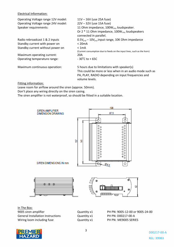
Fitting information: Leave room for airflow around the siren (approx. 50mm). Don’t place any wiring directly on the siren casing. The siren amplifier is not waterproof, so should be fitted in a suitable location.
In The Box: 9005 siren amplifier Quantity x1 PH PN: 9005-12-00 or 9005-24-00 General Installation Instructions Quantity x1 PH PN: D00217-00-A Wiring loom including fuse Quantity x1 PH PN: ME9005 SERIES
D00217-00-A
REL: 39983
4
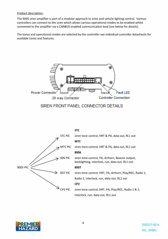
Product description:
The 9005 siren amplifier is part of a modular approach to siren and vehicle lighting control. Various controllers can connect to the siren which allows various operational modes to be enabled whilst connected to the amplifier via a CANBUS enabled communication lead (see below for details). The tones and operational modes are selected by the controller see individual controller datasheets for available tones and features.
STC
STC PIC siren tone control, HRT & PA, data out, RL1 out
MTC
MTC PIC siren tone control, HRT & PA, data out, RL1 out
8006
006 PIC siren tone control, PA, Airhorn, Beacon output, backlighting, interlock, run, data out, RL1 out
9005 PIC 8007
007 PIC siren tone control, HRT, PA, Airhorn, Play/REC, Radio 1,
Radio 2, interlock, run, data out, RL1 out
CP2
CP2 PIC siren tone control, HRT, PA, Play/REC, Radio 1 & 2,
Interlock, run, data out, RL1 out
D00217-00-A
REL: 39983
5
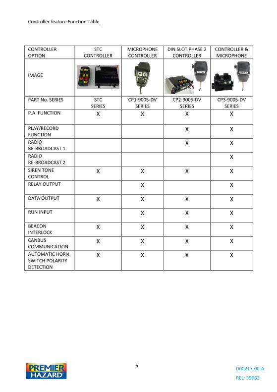
Controller feature Function Table
CONTROLLER OPTION
STC CONTROLLER
MICROPHONE CONTROLLER
DIN SLOT PHASE 2 CONTROLLER
CONTROLLER & MICROPHONE
IMAGE
PART No. SERIES STC SERIES
CP1-9005-DV SERIES
CP2-9005-DV SERIES
CP3-9005-DV SERIES
P.A. FUNCTION X X X X
PLAY/RECORD FUNCTION
X X
RADIO RE-BROADCAST 1
X X
RADIO RE-BROADCAST 2
X
SIREN TONE CONTROL
X X X X
RELAY OUTPUT X X
DATA OUTPUT X X X X
RUN INPUT X X X
BEACON INTERLOCK
X X X X
CANBUS COMMUNICATION
X X X X
AUTOMATIC HORN SWITCH POLARITY DETECTION
X X X X
D00217-00-A
REL: 39983
6
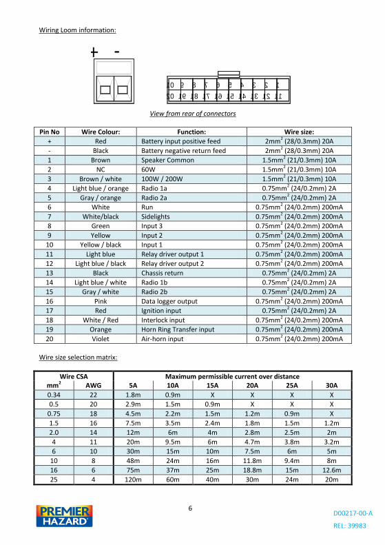
Wiring Loom information:
View from rear of connectors
Pin No Wire Colour: Function: Wire size:
+ Red Battery input positive feed 2mm2 (28/0.3mm) 20A
- Black Battery negative return feed 2mm2 (28/0.3mm) 20A
1 Brown Speaker Common 1.5mm2 (21/0.3mm) 10A
2 NC 60W 1.5mm2 (21/0.3mm) 10A
3 Brown / white 100W / 200W 1.5mm2 (21/0.3mm) 10A
4 Light blue / orange Radio 1a 0.75mm2 (24/0.2mm) 2A
5 Gray / orange Radio 2a 0.75mm2 (24/0.2mm) 2A
6 White Run 0.75mm2 (24/0.2mm) 200mA
7 White/black Sidelights 0.75mm2 (24/0.2mm) 200mA
8 Green Input 3 0.75mm2 (24/0.2mm) 200mA
9 Yellow Input 2 0.75mm2 (24/0.2mm) 200mA
10 Yellow / black Input 1 0.75mm2 (24/0.2mm) 200mA
11 Light blue Relay driver output 1 0.75mm2 (24/0.2mm) 200mA
12 Light blue / black Relay driver output 2 0.75mm2 (24/0.2mm) 200mA
13 Black Chassis return 0.75mm2 (24/0.2mm) 2A
14 Light blue / white Radio 1b 0.75mm2 (24/0.2mm) 2A
15 Gray / white Radio 2b 0.75mm2 (24/0.2mm) 2A
16 Pink Data logger output 0.75mm2 (24/0.2mm) 200mA
17 Red Ignition input 0.75mm2 (24/0.2mm) 2A
18 White / Red Interlock input 0.75mm2 (24/0.2mm) 200mA
19 Orange Horn Ring Transfer input 0.75mm2 (24/0.2mm) 200mA
20 Violet Air-horn input 0.75mm2 (24/0.2mm) 200mA
Wire size selection matrix:
Wire CSA Maximum permissible current over distance mm2 AWG 5A 10A 15A 20A 25A 30A
0.34 22 1.8m 0.9m X X X X
0.5 20 2.9m 1.5m 0.9m X X X
0.75 18 4.5m 2.2m 1.5m 1.2m 0.9m X
1.5 16 7.5m 3.5m 2.4m 1.8m 1.5m 1.2m
2.0 14 12m 6m 4m 2.8m 2.5m 2m
4 11 20m 9.5m 6m 4.7m 3.8m 3.2m
6 10 30m 15m 10m 7.5m 6m 5m
10 8 48m 24m 16m 11.8m 9.4m 8m
16 6 75m 37m 25m 18.8m 15m 12.6m
25 4 120m 60m 40m 30m 24m 20m
4
14
+
10
20
-
1516171819
7 6 589
111213
123
D00217-00-A
REL: 39983
7
Features:
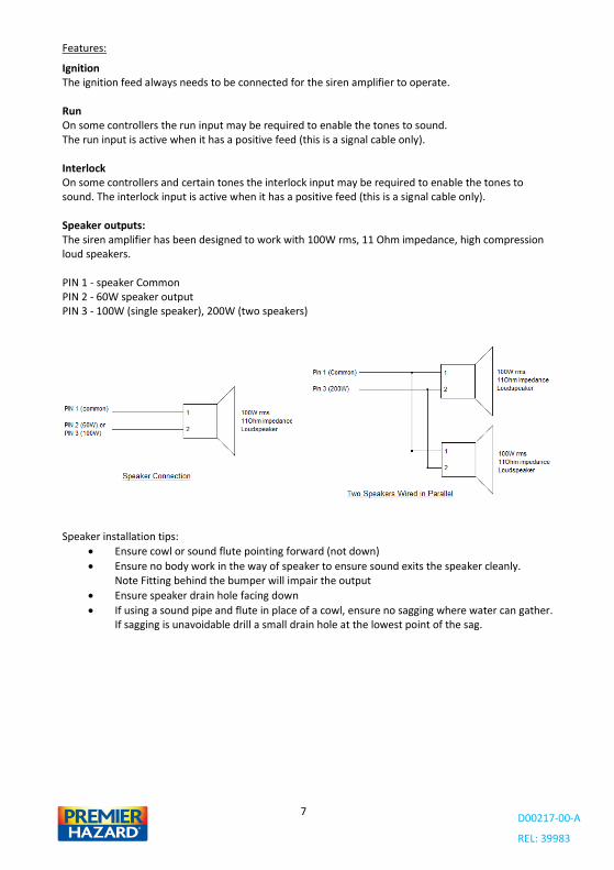
Ignition The ignition feed always needs to be connected for the siren amplifier to operate. Run On some controllers the run input may be required to enable the tones to sound. The run input is active when it has a positive feed (this is a signal cable only). Interlock On some controllers and certain tones the interlock input may be required to enable the tones to sound. The interlock input is active when it has a positive feed (this is a signal cable only). Speaker outputs: The siren amplifier has been designed to work with 100W rms, 11 Ohm impedance, high compression loud speakers. PIN 1 - speaker Common PIN 2 - 60W speaker output PIN 3 - 100W (single speaker), 200W (two speakers)
Speaker installation tips:
Ensure cowl or sound flute pointing forward (not down)
Ensure no body work in the way of speaker to ensure sound exits the speaker cleanly. Note Fitting behind the bumper will impair the output
Ensure speaker drain hole facing down
If using a sound pipe and flute in place of a cowl, ensure no sagging where water can gather. If sagging is unavoidable drill a small drain hole at the lowest point of the sag.
D00217-00-A
REL: 39983
8
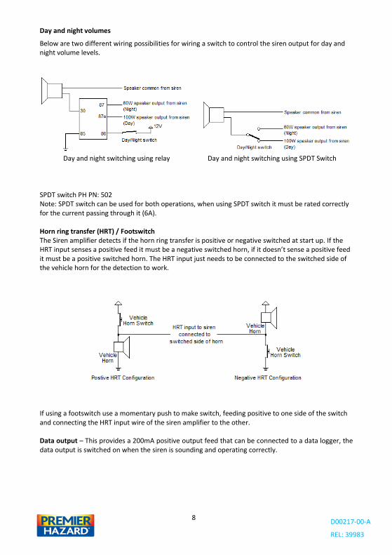
Day and night volumes
Below are two different wiring possibilities for wiring a switch to control the siren output for day and night volume levels.
Day and night switching using relay Day and night switching using SPDT Switch SPDT switch PH PN: 502 Note: SPDT switch can be used for both operations, when using SPDT switch it must be rated correctly for the current passing through it (6A). Horn ring transfer (HRT) / Footswitch The Siren amplifier detects if the horn ring transfer is positive or negative switched at start up. If the HRT input senses a positive feed it must be a negative switched horn, if it doesn’t sense a positive feed it must be a positive switched horn. The HRT input just needs to be connected to the switched side of the vehicle horn for the detection to work.
If using a footswitch use a momentary push to make switch, feeding positive to one side of the switch and connecting the HRT input wire of the siren amplifier to the other. Data output – This provides a 200mA positive output feed that can be connected to a data logger, the data output is switched on when the siren is sounding and operating correctly.
D00217-00-A
REL: 39983
9
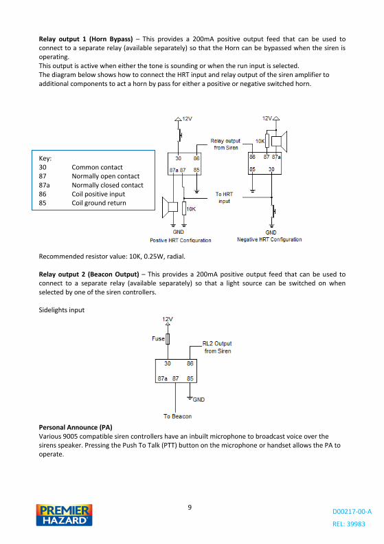
Relay output 1 (Horn Bypass) – This provides a 200mA positive output feed that can be used to connect to a separate relay (available separately) so that the Horn can be bypassed when the siren is operating. This output is active when either the tone is sounding or when the run input is selected. The diagram below shows how to connect the HRT input and relay output of the siren amplifier to additional components to act a horn by pass for either a positive or negative switched horn.
Recommended resistor value: 10K, 0.25W, radial. Relay output 2 (Beacon Output) – This provides a 200mA positive output feed that can be used to connect to a separate relay (available separately) so that a light source can be switched on when selected by one of the siren controllers. Sidelights input
Personal Announce (PA) Various 9005 compatible siren controllers have an inbuilt microphone to broadcast voice over the sirens speaker. Pressing the Push To Talk (PTT) button on the microphone or handset allows the PA to operate.
Key: 30 Common contact 87 Normally open contact 87a Normally closed contact 86 Coil positive input 85 Coil ground return
D00217-00-A
REL: 39983
10
Record and Playback Placing the 9005 compatible siren controller in the play mode allows up to 30 seconds of recorded message to be broadcast over the sirens speaker on a continuous loop.
Pressing and holding the PTT button records from the microphone as long as the PTT is held in.
To wipe the message quickly press and release the PTT button while the play mode is selected.
Volume control The volume for the audio functions (PA, Play, Radio rebroadcast) can be adjusted on some of the 9005 compatible siren controllers. This is either a volume knob on the controller or Volume plus and minus buttons. Note the volume cannot be adjusted on the STC and MTC handsets and is pre-set to the highest setting.
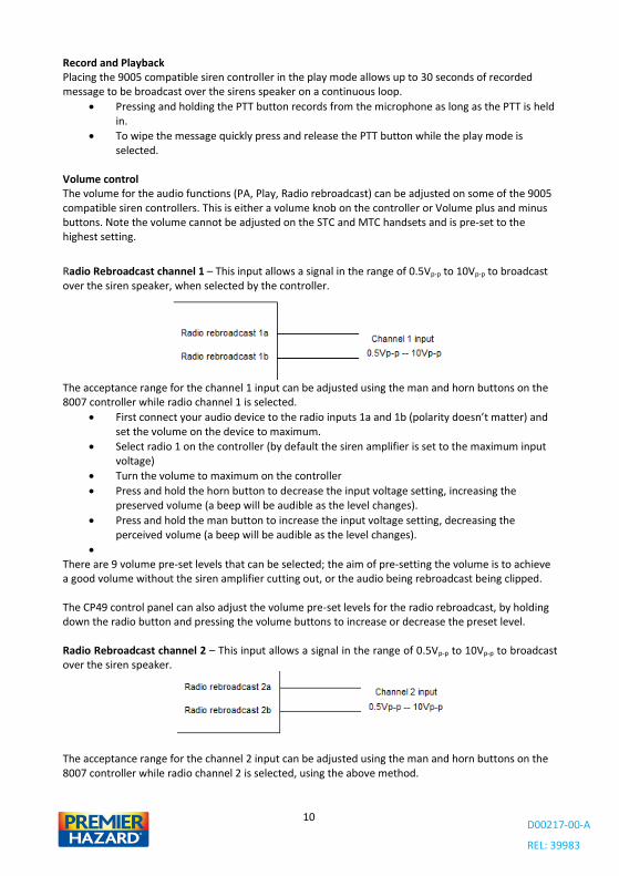
Radio Rebroadcast channel 1 – This input allows a signal in the range of 0.5Vp-p to 10Vp-p to broadcast over the siren speaker, when selected by the controller.
The acceptance range for the channel 1 input can be adjusted using the man and horn buttons on the 8007 controller while radio channel 1 is selected.
First connect your audio device to the radio inputs 1a and 1b (polarity doesn’t matter) and set the volume on the device to maximum.
Select radio 1 on the controller (by default the siren amplifier is set to the maximum input voltage)
Turn the volume to maximum on the controller
Press and hold the horn button to decrease the input voltage setting, increasing the preserved volume (a beep will be audible as the level changes).
Press and hold the man button to increase the input voltage setting, decreasing the perceived volume (a beep will be audible as the level changes).
There are 9 volume pre-set levels that can be selected; the aim of pre-setting the volume is to achieve a good volume without the siren amplifier cutting out, or the audio being rebroadcast being clipped. The CP49 control panel can also adjust the volume pre-set levels for the radio rebroadcast, by holding down the radio button and pressing the volume buttons to increase or decrease the preset level. Radio Rebroadcast channel 2 – This input allows a signal in the range of 0.5Vp-p to 10Vp-p to broadcast over the siren speaker.
The acceptance range for the channel 2 input can be adjusted using the man and horn buttons on the 8007 controller while radio channel 2 is selected, using the above method.
D00217-00-A
REL: 39983
11
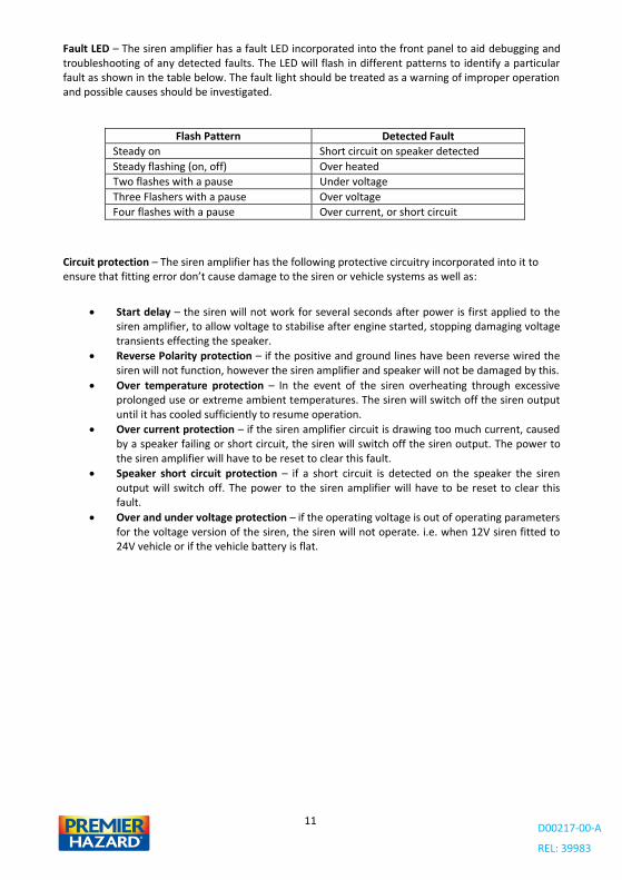
Fault LED – The siren amplifier has a fault LED incorporated into the front panel to aid debugging and troubleshooting of any detected faults. The LED will flash in different patterns to identify a particular fault as shown in the table below. The fault light should be treated as a warning of improper operation and possible causes should be investigated.
Flash Pattern Detected Fault
Steady on Short circuit on speaker detected
Steady flashing (on, off) Over heated
Two flashes with a pause Under voltage
Three Flashers with a pause Over voltage
Four flashes with a pause Over current, or short circuit
Circuit protection – The siren amplifier has the following protective circuitry incorporated into it to ensure that fitting error don’t cause damage to the siren or vehicle systems as well as:
Start delay – the siren will not work for several seconds after power is first applied to the siren amplifier, to allow voltage to stabilise after engine started, stopping damaging voltage transients effecting the speaker.
Reverse Polarity protection – if the positive and ground lines have been reverse wired the siren will not function, however the siren amplifier and speaker will not be damaged by this.
Over temperature protection – In the event of the siren overheating through excessive prolonged use or extreme ambient temperatures. The siren will switch off the siren output until it has cooled sufficiently to resume operation.
Over current protection – if the siren amplifier circuit is drawing too much current, caused by a speaker failing or short circuit, the siren will switch off the siren output. The power to the siren amplifier will have to be reset to clear this fault.
Speaker short circuit protection – if a short circuit is detected on the speaker the siren output will switch off. The power to the siren amplifier will have to be reset to clear this fault.
Over and under voltage protection – if the operating voltage is out of operating parameters for the voltage version of the siren, the siren will not operate. i.e. when 12V siren fitted to 24V vehicle or if the vehicle battery is flat.
D00217-00-A
REL: 39983
12
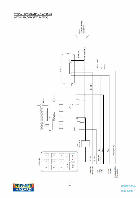
TYPICAL INSTALLATION DIAGRAMS 9005 & STC/MTC (STC SHOWN)
D00217-00-A
REL: 39983
13
Brief Operational description:
Pressing any of the keys 1 to 9, will switch the output 1 to 9 on or off.
Pressing the siren key or 999 key will put the siren into standby mode allowing the siren to be started by either pressing the vehicle horn or the siren key again. Successive presses will cycle though the available tones selected by the handset.
To stop the siren sounding either; press and hold the siren button, or press the horn twice in quick succession, this leaves the siren in standby so it can be quickly restarted.
Pressing reset stops the siren sounding and switches the outputs off
999 and arrival buttons can be programmed to switch multiple outputs on or off, when pressed.
D00217-00-A
REL: 39983
14
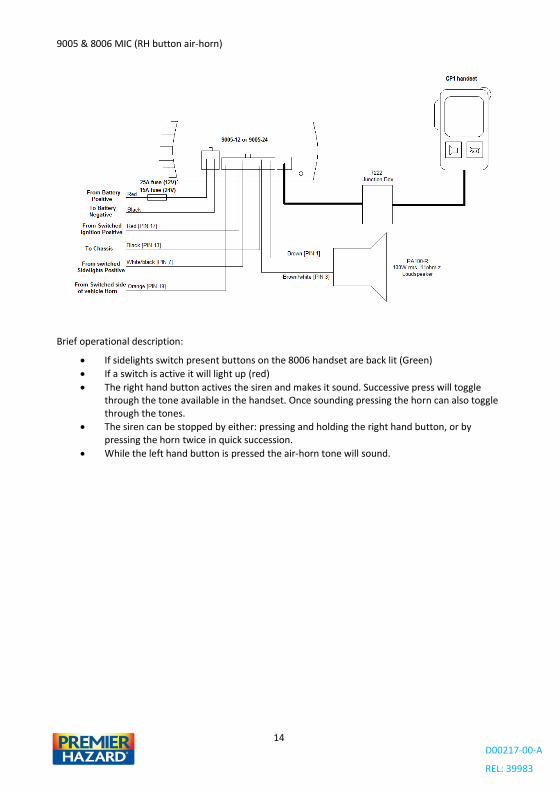
9005 & 8006 MIC (RH button air-horn)
Brief operational description:
If sidelights switch present buttons on the 8006 handset are back lit (Green)
If a switch is active it will light up (red)
The right hand button actives the siren and makes it sound. Successive press will toggle through the tone available in the handset. Once sounding pressing the horn can also toggle through the tones.
The siren can be stopped by either: pressing and holding the right hand button, or by pressing the horn twice in quick succession.
While the left hand button is pressed the air-horn tone will sound.
D00217-00-A
REL: 39983
15
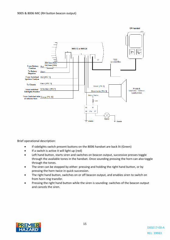
9005 & 8006 MIC (RH button beacon output)
Brief operational description:
If sidelights switch present buttons on the 8006 handset are back lit (Green)
If a switch is active it will light up (red)
Left hand button, starts siren and switches on beacon output, successive presses toggle through the available tones in the handset. Once sounding pressing the horn can also toggle through the tones.
The siren can be stopped by either: pressing and holding the right hand button, or by pressing the horn twice in quick succession.
The right hand button, switches on or off beacon output, and enables siren to switch on from horn ring transfer.
Pressing the right hand button while the siren is sounding: switches of the beacon output and cancels the siren.
D00217-00-A
REL: 39983
16
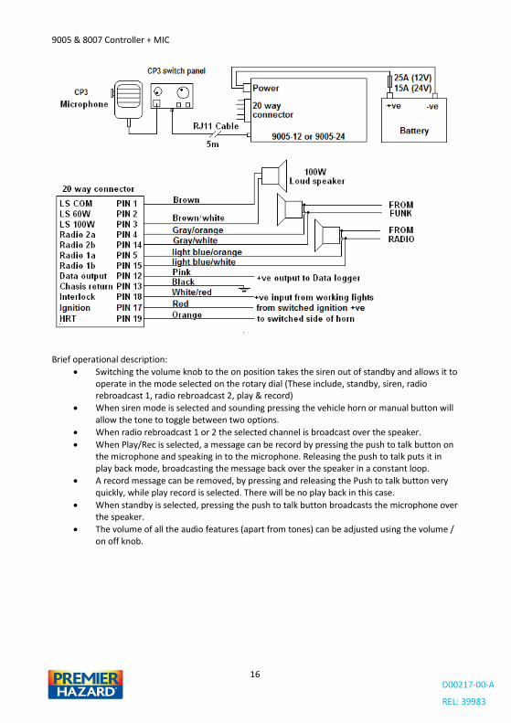
9005 & 8007 Controller + MIC
Brief operational description:
Switching the volume knob to the on position takes the siren out of standby and allows it to operate in the mode selected on the rotary dial (These include, standby, siren, radio rebroadcast 1, radio rebroadcast 2, play & record)
When siren mode is selected and sounding pressing the vehicle horn or manual button will allow the tone to toggle between two options.
When radio rebroadcast 1 or 2 the selected channel is broadcast over the speaker.
When Play/Rec is selected, a message can be record by pressing the push to talk button on the microphone and speaking in to the microphone. Releasing the push to talk puts it in play back mode, broadcasting the message back over the speaker in a constant loop.
A record message can be removed, by pressing and releasing the Push to talk button very quickly, while play record is selected. There will be no play back in this case.
When standby is selected, pressing the push to talk button broadcasts the microphone over the speaker.
The volume of all the audio features (apart from tones) can be adjusted using the volume / on off knob.
D00217-00-A
REL: 39983
17
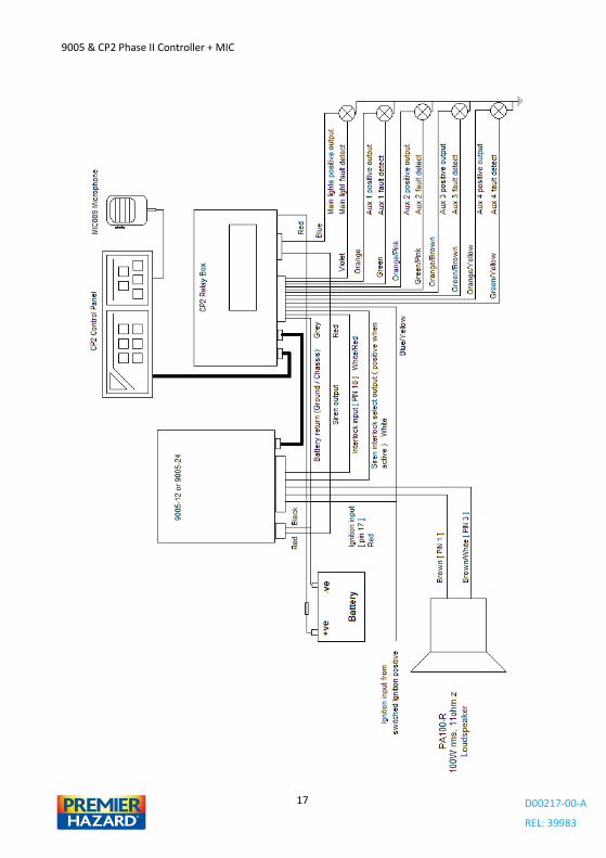
9005 & CP2 Phase II Controller + MIC
D00217-00-A
REL: 39983
18
Brief Operational Description:
Pressing the main lights button turns the main light output on or off and allow the siren to sound when on.
Pressing the Aux 1 button turns the Aux 1 output on or off.
Pressing the Aux 2 button turns the Aux 2 output on or off.
Pressing the Aux 3 button turns the Aux 3 output on or off.
Pressing the Aux 4 button turns the Aux 4 output on or off.
Pressing the S/L button switches between the town and country siren sounds
Pressing the Siren button activates the siren tones, if the main light button is active and working correctly.
Pressing the Volume up key increases the volume for PA, Radio Rebroadcast and Play back
Pressing the Volume down key increases the volume for PA, Radio Rebroadcast and Play back
Pressing the PA button broadcasts the microphone input over the speaker
Pressing the Radio Key broadcasts the radio rebroadcast input over the speaker
Pressing the REC/PLAY key allows message to be recorded and played back over the speaker.
D00217-00-A
REL: 39983
19
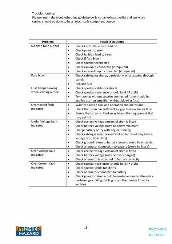
Troubleshooting: Please note: - the troubleshooting guide below is not an exhaustive list and any work carried should be done so by an electrically competent person.
Problem Possible solutions
No siren tone output Check Controller is switched on
Check power to siren
Check ignition feed to siren
Check if fuse blown
Check speaker connected
Check run input connected (if required)
Check interlock input connected (if required)
Fuse blown Check cabling for shorts, particularly wires passing through panels
Replace fuse
Fuse Keeps blowing when starting a tone
Check speaker cables for shorts
Check speaker resistance (should be 4.4R ± 1R)
Try running without speaker connected (tone should be audible at siren amplifier, without blowing fuse)
Overheated fault indicated
Wait for siren to cool and operation should resume.
Check that siren has sufficient air gap to allow for air flow.
Ensure that siren is fitted away from other equipment that may get hot.
Under Voltage fault indicated
Check correct voltage version of siren is fitted
Check battery voltage (may be below minimum)
Charge battery or try with engine running
Check cabling is rated correctly (if under rated may have a voltage drop down line)
Check ground return to battery (ground could be unstable)
Check alternator connection to battery (could be loose)
Over Voltage fault indicated
Check correct voltage version of siren is fitted
Check battery voltage (may be over charged)
Check alternator is attached to battery correctly
Over Current fault indicated
Check speaker resistance (should be 4.4R ± 1R)
Check speaker cable for shorts
Check alternator connected to battery
Check power to siren (could be unstable, due to alternator problem, grounding, cabling or another device fitted to vehicle)
D00217-00-A
REL: 39983
20
WA
RN
ING
TH
E W
OR
LD®
Em
erge
ncy
Ser
vice
an
d U
tilit
y W
arn
ing
Syst
ems
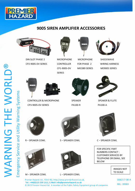
9005 SIREN AMPLIFIER ACCESSORIES
DIN SLOT PHASE 2 MICROPHONE MICROPHONE SHOCKWAVE
CP2-9005-DV SERIES CONTROLLER FOR PHASE 2 WIRING HARNESS
CP1-9005-DV MIC089 SERIES ME9005 SERIES
SERIES
CONTROLLER & MICROPHONE SPEAKER SPEAKER & FLUTE
CP3-9005-DV SERIES PA100-R PA100-A
R – SPEAKER COWL S – SPEAKER COWL C – SPEAKER COWL
M – SPEAKER COWL L – SPEAKER COWL
Premier Hazard Ltd., YO16 4SJ, http://www.premierhazard.co.uk, Tel.: +44(0)113 239 1111, E-Mail: [email protected] © 2013 Premier Hazard ltd. A member of the Public Safety Equipment group of companies
IMAGES NOT TO SCALE
D00217-00-A
REL: 39983
FOR SPECIFIC PART NUMBERS CONTACT : CUSTOMER SERVICES BY TELEPHONE OR EMAIL, SEE BELOW