wang laboratories, incorporated svs/os cap 1 · during vap, the newly assigned team reviews design...
TRANSCRIPT

carumNATIONAL COMPUTER SECURITY CENTER
AD-A247 238
FINAL EVALUATION REPORT
Wang Laboratories, Incorporated
SVS/OS CAP 1.0
28 September 1990 f92-05766
Approved for Public Release:Distribution Unlimited
92 3 04 010
Ace..slaa for
FINAL EVALUATION REPORT Clog~e
Wang Laboratories, Inc.
SVS/OS CAP 1.0 itbiiz/
DTIC -Dist spea.1.
COPYNS PF C TED)
NATIONAL
COMPUTER SECURITY CENTER
9800 Savage RoadFort George G. MeadeMaryland 20755-6000
September 28, 1990
Report No. CSC-EPL-90/004Library No. S236,000

Final Evaluation Report Wang SVS/OSFOREWORD
FOREWORD
This publication, the Final Evaluation Report, Wang Laboratories, Inc., SVS/OS CAP 1.0, is being issuedby the National Computer Security Center under the authority of and in accordance with DoD Directive5215.1, "Computer Security Evaluation Center." The purpose of this report is to document the results ofthe formal evaluation of Wang SVS/OS CAP 1.0. The requirements stated in this report are taken fromDepartment of Defense Trusted Computer System Evaluation Criteria, dated 26 December 1985.
Approved:
Director,National Computer Security Center
FINAL: September 28, 1990

Final Evaluation Report Wang SVS/OS
ACKNOWLEDGEMENTS
ACKNOWLEDGEMENTS
Team Members
Timothy J. Bergendahl The MITRE CorporationDuane A. Souder Bedford, MA
Anthony J. Apted National Security AgencyJames L. Arnold Jr. Trusted Products and NetworkRonald J. Bottomly Security Evaluation Division
R. Kris Britton Fort George G. Meade, MD
Technical support was also provided by Deborah Downs, Virgil Gligor, Paul Hager, Karina Hasler, KimMcNicbolas, Kathleen M. Tessier, Grant Wagner, and Allen Wentink.
For their contributions to this document, acknowledgement is given to Frank Belvin, Richard B. Newton,and David W. Summers.
iiiFINAL: September 28, 1990

Final Evaluation Report Wang SVS/0S
TABLE OF CONTENTS
ContentsFOREWORD ii
ACKNOWLEDGEMENTS iii
EXECUTI7VE SUMMARY Viii
1 ]Introduction 11.1 Evaluation Process Overview............................................11.2 Background and History................................................21.3 Document Organization................................................31.4 Conventions....................................................... 3
2 System Overview 42.1 Hardware Architecture................................................ 4
2.1.1 The Central Complex............................................42.1.2 Devices..................................................... 202.1.3 Hardware Diagnostics........................................... 23
2.2 Software Architecture................................................ 252.2.1 Kernel Software................................................ 252.2.2 Task Execution................................................ 252.2.3 Task Virtual Memory........................................... 262.2.4 Task Management.............................................. 272.2.5 Process Levels................................................ 292.2.6 Wait Levels.................................................. 292.2.7 Job Processing................................................ 302.2.8 User Interfaces................................................ 302.2.9 File System.................................................. 332.2.10 The Data Management System..................................... 342.2.11 1/O Management ............................................ 352.2.12 Interprocess Communication....................................... 362.2.13 The Audit Mechanism........................................... 362.2.14 Print Processing. .. .. .. ... ... ... ... ... ... ... .... ... ... .. 382.2.15 System Initialization .. .. .. .. ... ... ... ... ... ... ... ... .... .. 39
2.3 Trusted Utilities. .. .. .. ... ... ... ... .... ... ... ... ... ... ... ... 402.3.1 BACKUP.. .. .. ... ... ... ... ... ... ... ... .... ... ... ... .. 402.3.2 BUILDALT and SORT. .. .. .. ... ... ... .... ... ... ... ... ... .... 402.3.3 DISKIIIT .. .. .. .. ... ... ... ... ... ... .... ... ... ... ... .. 412.3.4 FLopyDup .. .. .. .. ... ... ... ... ... .... ... ... ... ... ... .. 412.3.5 GROUPEDT .. .. .. .. ... ... ... ... ... .... ... ... ... ... ... .. 412.3.6 SLFORMAT .. .. .. .. ... ... ... ... ... .... ... ... ... ... ... .. 422.3.7 SLPRIT . .. .. .. .. ... ... ... ... ... ... .... ... ... ... ... .. 422.3.8 SYMBOLIC DEBUGGER System Services .. .. .. .. .... ... ... ... ... .... 422.3.9 TAPEIIIT .. .. .. .. ... ... ... ... ... ... .... ... ... ... ... .. 432.3.10 VOLCOPY. .. .. .. .. ... ... ... ... ... ... ... .... ... ... ... .. 432.3.11 VSSECURE .. .. .. .. ... ... ... ... .... ... ... ... ... ... ... .. 43
2 4 TCB Protected Resources. .. .. .. .. ... .... ... ... ... ... ... ... ... .. 442.4.1 Subjects. .. .. .. .. ... ... ... ... ... ... ... .... ... ... ... .. 44
ivFINAL: September 28, 1990
Final Evaluation Report Wang SVS/O5TABLE OF CONTENTS
2.4.2 Objects.................................................. 442.5 SVS/OS Protection Mechanisms....................................... 47
2.5.1 Identification and Authentication.................................. 472.5.2 Discretionary Access Control.................................... 482.5.3 Tasks .. .. .. .. .. ... .. ... ... .. ... .. ... ... .. ... ... .. .. 502.5.4 Object Reuse .. .. .. .. .. .. ... .. ... ... .. ... .. ... ... .. .... 51
3 Rating Maintenance Phase 53
4 Evaluation as a C2 System 554.1 Discretionary Access Control. .. .. .. .. .. ... ... .. ... .. ... ... .. ... .. 554.2 Object Reuse. .. .. .. .. .. ... .. ... .. ... ... .. ... ... .. ... .. .... 564.3 Identification and Authentication .. .. .. .. .. .. ... .. ... ... .. ... .. ... .. 564.4 Audit ... .. .. .. ... .. ... .. ... ... .. ... .. ... ... .. ... ... .. .. 574.5 System Architecture. .. .. .. .. .. ... .. ... ... .. ... .. ... ... .. ... .. 584.6 System Integrity. .. .. .. .. .. ... ... .. ... .. ... ... .. ... ... .. ..... 594.7 Security Testing. .. .. .. .. ... .. ... ... .. ... .. ... ... .. ... ... ... 594.8 Security Features User's Guide. .. .. .. .. .. ... ... .. ... .. ... ... .. ..... 624.9 Trusted Facility Manual .. .. .. .. .. .. ... ... .. ... .. ... ... .. ... ..... 624.10 Test Documentation. .. .. .. .. ...... .. .. .. .. .. ... ... .. ... ... .. .. 634.11 Design Documentation. .. .. .. .. .. .. ... .. ... ... .. ... ... .. ... .. .. 64
5 Evaluator's Comments 65
A Evaluated Hardware Components 66A.1I CPU Types. .. .. .. .. .. ... .. ... ... .. ... .. ... ... .. ... ... .. .. 66A.2 CPU Controllers. .. .. .. .. .. ... .. ... ... .. ... ... .. ... .. ... ..... 67
A.2.1 Disk Controllers .. .. .. .. .. ... .. ... ... .. ... .. ... ... .. .... 67A.2.2 Magnetic Tape Controllers. .. .. .. .. ... .. ... ... .. ... .. ... ..... 68A.2.3 Serial Device Controllers .. .. .. .. .. .. .. ... .. ... ... .. ... .. .... 69A.2.4 Asynchronous Device Controllers. .. .. .. .. .. .. ... ... .. ... .. ... .. 69A.2.5 Local Asynchronous Device Controllers .. .. .. .. .. ... ... .. ... .. .... 70A.2.6 Wangnet / Peripheral Band Controllers .. .. .. .. .. ... .. ... .. ... ..... 70A.2.7 Fiberway I & 11 Fiber Optics. .. .. .. .. .. ... .. ... .. ... ... .. .... 71
A.3 Peripheral Devices .. .. .. .. .. .. ... ... .. ... ... .. ... .. ... ... .. .. 71A.3.1 Disk Drives .. .. .. .. .. .. ... .. ... ... .. ... .. ... ... .. ... .. 71A.3.2 Tape Drives. .. .. .. .. .. .. ... .. ... ... .. ... .. ... ... .. ..... 73A.3.3 Workstations .. .. .. .. .. .. ... ... .. ... .. ... ... .. ... ... ... 74A.3.4 Printers .. .. .. .. .. .. ... .. ... ... .. ... .. ... ... .. ... ..... 74
B Evaluated Software Components 76
C Glossary 78
vFINAL: September 28, 1990
Final Evaluation Report Wang SVS/OSLIST OF FIGURES
List of Figures
2.1 Address Translation................................................. 132.2 Bus Adapter and I/O Processor Usage .. .. .. .. .. ... ... ... .... ... ... .... 172.3 Bus Processor and Device Adapter Usage .. .. .. .. ... ... ... ... .... ... .... 172.4 1/0 Controller Usage. .. .. .. .. .. ... ... ... .... ... ... ... ... ... ... 182.5 0/ Coprocessor Usage .. .. .. .. .. .. .... ... ... ... ... ... ... ... ..... 182.6 Virtual Memory Map. .. .. .. .. .. ... ... ... .... ... ... ... ... ... ... 28
viFINAL: September 28, 1990

Final Evaluation Report Wang SVS/OS
LIST OF TABLES
List of Tables
2.1 Control Registers........................................................ 62.2 Program Control Word Description. .. .. .. .. ... ... ... ... ... ... ... ..... 82.3 CP Type Summary. .. .. .. .. ... ... ... ... ... ... ... ... ... .... .... 10
viiFINAL: September 28, 1990
Final Evaluation Report Wang SVS/OS
EXECUTIVE SUMMARY
EXECUTIVE SUMMARY
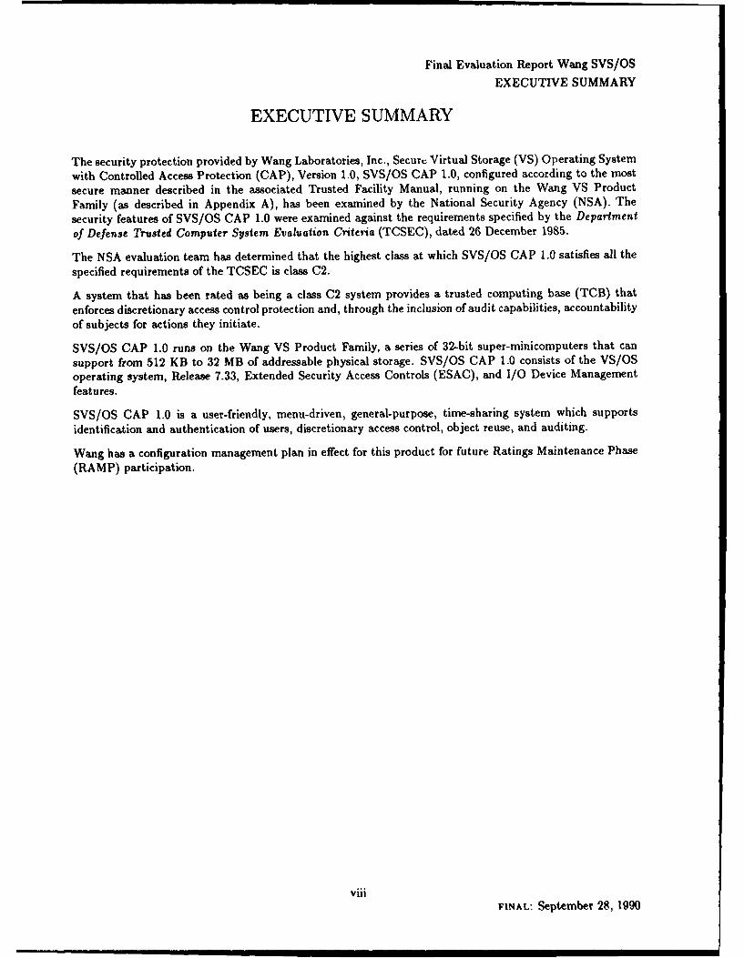
The security protection provided by Wang Laboratories, Inc., Securt. Virtual Storage (VS) Operating System
with Controlled Access Protection (CAP), Version 1.0, SVS/OS CAP 1.0, configured according to the most
secure manner described in the associated Trusted Facility Manual, running on the Wang VS Product
Family (as described in Appendix A), has been examined by the National Security Agency (NSA). The
security features of SVS/OS CAP 1.0 were examined against the requirements specified by the Department
of Defense Trusted Computer System Evaluation Criteria (TCSEC), dated 26 December 1985.
The NSA evaluation team has determined that the highest class at which SVS/OS CAP 1.0 satisfies all the
specified requirements of the TCSEC is class C2.
A system that has been rated as being a class C2 system provides a trusted computing base (TCB) that
enforces discretionary access control protection and, through the inclusion of audit capabilities, accountability
of subjects for actions they initiate.
SVS/OS CAP 1.0 runs on the Wang VS Product Family, a series of 32-bit super-minicomputers that can
support from 512 KB to 32 MB of addressable physical storage. SVS/OS CAP 1.0 consists of the VS/OSoperating system, Release 7.33, Extended Security Access Controls (ESAC), and I/O Device Managementfeatures.
SVS/OS CAP 1.0 is a user-friendly, menu-driven, general-purpose, time-sharing system which supports
identification and authentication of users, discretionary access control, object reuse, and auditing.
Wang has a configuration management plan in effect for this product for future Ratings Maintenance Phase(RAMP) participation.
viiiFINAL: September 28, 1990

Final Evaluation Report Wang SVS/OS
Chapter 1
Introduction
In August 1989 the National Security Agency (NSA), Trusted Products and Network Security EvaluationDivision, began a formal product evaluation of SVS/OS CAP 1.0, a product of Wang Laboratories, Inc..The objective of this evaluation was to rate SVS/OS CAP 1.0 against the Department of Defense TrustedComputer System Evaluation Criteria (TCSEC) [10], and to place it on the Evaluated Products List (EPL)with a final rating. This report documents the results of that evaluation.
Material for this report was gathered by the NSA formal evaluation team through documentation, interactionwith system developers, and experience using Wang Laboratories, Inc., systems.
1.1 Evaluation Process Overview
The Department of Defense Computer Security Center was established in January 1981 to encourage thewidespread availability of trusted computer systems for use by facilities processing classified or other sensitiveinformation. In August 1985 the name of the organization was changed to the National Computer SecurityCenter. In order to assist in assessing the degree of trust one could place in a given computer system, theDoD Trusted Computer System Evaluation Criteria (TCSEC) was written. The TCSEC establishes specificrequirements that a computer system must meet in order to achieve a predefined level of trustworthiness. TheTCSEC levels are arranged hierarchically into four major divisions of protection, each with certain security-relevant characteristics. These divisions are in turn subdivided into classes. To determine the division andclass at which all requirements are met by a system, the system must be evaluated against the TCSEC byan NSA, Trusted Product and Network Security evaluation team.
The NSA supports the creation of secure computer products in varying stages of development from initialdesign to those that are commercially available. Preliminary to an evaluation, pruducts must go throughthe Proposal Review Phase. This phase includes an assessment of the vendor's capability to create a securesystem and complete the evaluation process. To support this assessment, a Preliminary Technical Review(PTR) of the system is done by the NSA. This consists ef a quick review of the current state of the systemby a small, but expert, team and the creation of a short report on the state of the system. If a vendor passesthe Proposal Review Phase they will enter a support phase preliminary to evaluation. This support phasehas two steps, the Vendor Assistance Phase (VAP) and the Design Analysis Phase (DAP). During VAP, thenewly assigned team reviews design specifications and answers technical questions that the vendor may haveabout the ability of the design to meet the requirements. A product will stay in VAP until the vendor'sdesign, design documentation, and other required evidence for the target TCSEC class are complete and thevendor is well into implementation. At that time, the support moves into DAP.
The primary thrust of DAP is an in-depth examination of a manufacturer's design for either a new trustedproduct or for security enhancements to an existing product. DAP is based on design documentation andinformation supplied by the industry source, it involves little "hands on" use of the system, but during thisphase the vendor should virtually comnlete implementation of the product. DAP results in the production
FINAL: September 28, 1990

Final Evaluation Report Wang SVS/OS
1.2. BACKGROUND AND HISTORY
of an Initial Product Assessment Report (IPAR) by the NSA assessment team. The IPAR documents theteam s understanding of the system based on the information presented by the vendor. Because the IPARcontains proprietary information and represents only a preliminary analysis by the NSA, distribution isrestricted to the vendor and the NSA.
Products that have completed the support phase with the successful creation of the IPAR, enter formalevaluation. Products entering formal evaluation must be complete security systems. In addition, the releasebeing evaluated must not undergo any additional development. The formal evaluation is an analysis of thehardware and software components of t system, all system documentation, and a mapping of the securityfeatures and assurances to the TCSEC. The analysis performed during the formal evaluation requires "handson" testing (i.e., functional testing and, if applicable, penetration testing). The formal evaluation results inthe production of a final report and an E,,1uated Products List entry. The final report is a sum.aiary ofthe evaluation and includes the EPL rating which indicates the final class at which the product satisfies allTCSEC requirements in terms of both features and assurances. The final report and EPL entry are madepublic.
After completion of the Formal evaluation phase, products rated at BI and below enter the rating mainte-nance phase (RAMP). The rating maintenance phase provides a mechanism to entend the previous ratingto a new version of an evaluated comp, ter system product. As enhancements are made to the computerproduct the ratings maintenance phasc ensures that the level of trust is not degraded.
Rating Maintenance is accomplished by using qualified vendor personnel to manage the change process of therated product during the maintenance cycle. These qualified vendor personnel must have strong technicalknowledge of computer security and of their computer product. These trained personnel will oversee thevendor's computer product modification process. They will demonstrate to the Trusted Product and NetworkSecurity Evaluation Division that any modification or enhancements applied to the product preserve thesecurity mechanisms and maintain the assurances required by the TCSEC for the rating previously awardedto the evaluated prodtJ.
1.2 Background and History
Wang Laboratories, Inc., which is headquartered in Lowell, Massachusetts, was founded in 1951 in Boston,Massachusetts by Dr. An Wang. The company was initially involved with developing word processing toolsfor use on small computer systems, and became a leader in this field. Today Wang manufactures and sells awide range of computer systems.
In October 1978 the first VS systems were introduced. The VS60 and the VS80 belonged to the 2200 VSfamily. This family was based on a 32-bit machine architecture using a 16-bit bus. Word processing wasfirst integrated with data processing in the VS80. In June 1979 the first 32-bit system, the VS100, wasintroduced.
Today, the product line is called the Wang VS Product Family. All Wang VS systems are based on a 32-bitmachine architecture, and all Wang VS systems implement the same VS/OS operating system.
Since its inception, Wang VS/OS has provided identification and authentication of users and access controlson files, the latter via file protection classes. With the Release 7 Series architectural changes were made tothe operatiag system to provide a basis for a more secure system. Some of these changes include improvedauditing of security relevant events, password enhancements, object reuse, and the implementation of access
2FINAL: September 28, 1990
Final Evaluation Report Wang SVS/OS1.3. DOCUMENT ORGANIZATION
control lists.
1.3 Document Organization
This report consists of five chapters and four appendices. Chapter 1 is an intr3duction. Chapter 2 is a systemoverview and provides information about SVS/OS hardware and software architecture, including protectionmechanisms. Chapter 3 includes a discussion of the Ratin*es Maintenance Phase (RAMP) pertaining toSVS/OS. Chapter 4 presents a mapping of SVS/OS features to the C2 requirements in the TCSEC. Chapter5 contains evaluator's comments. The four appendices identify the evaluated hardware components, theevaluated software components, provide a glossary, and present a bibliography.
1.4 Conventions
For consistency with Wang's conventions, the term "workstation" is used rather than "terminal" throughoutthis report. Also, each time a Wang-specific term is defined, it is emphasized only where it is defined andused normally elsewhere.
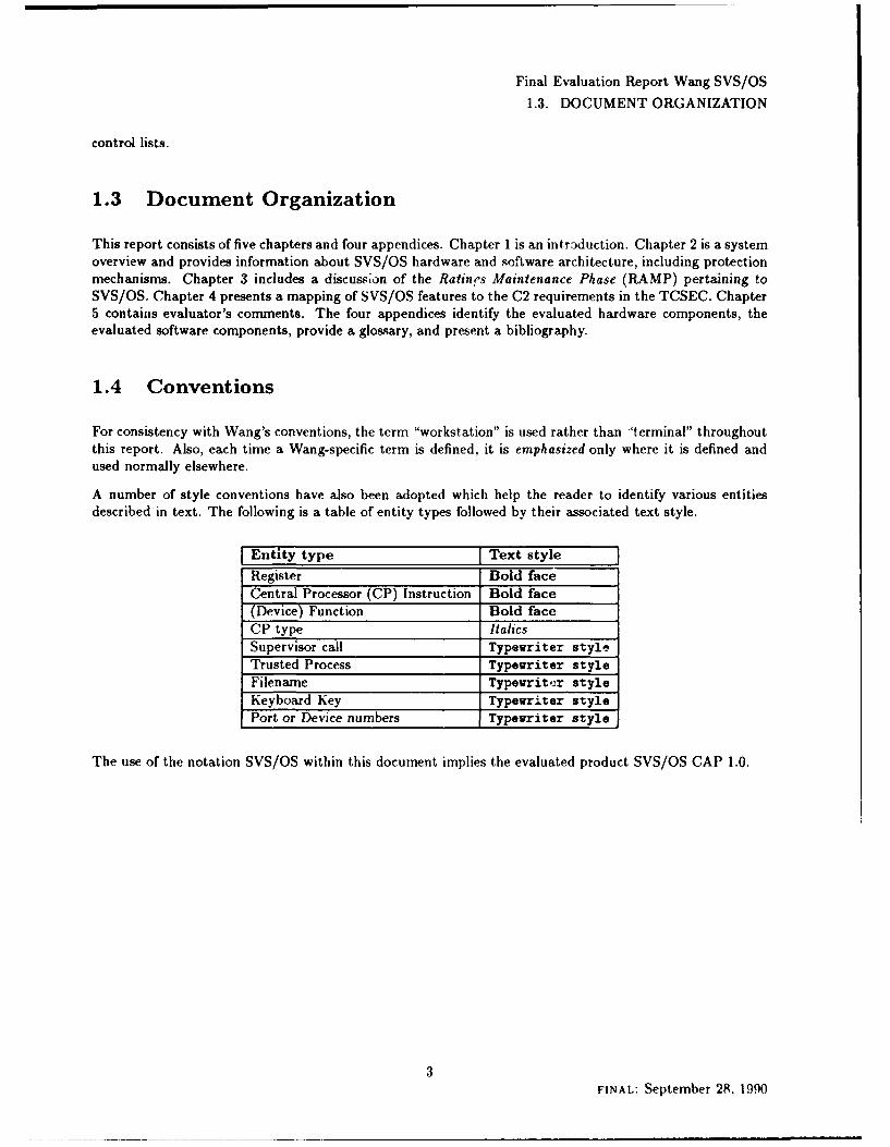
A number of style conventions have also been adopted which help the reader to identify various entitiesdescribed in text. The following is a table of entity types followed by their associated text style.
Entity type Text style
Register Bold faceCentral Processor (CP) Instruction Bold face(Device) Function Bold faceCP type ItalicsSupervisor call Typewriter style
Trusted Process Typewriter styleFilename Typewriter styleKeyboard Key Typewriter stylePort or Device numbers Typewriter style
The use of the notation SVS/OS within this document implies the evaluated product SVS/OS CAP 1.0.
3FINAL: September 28, 1990

Final Evaluation Report Wang SVS/OS
Chapter 2
System Overview
2.1 Hardware Architecture
The evaluated system is comprised of SVS/OS CAP 1.0 running on a base Central Processor (CP) with a col-
lection of attached controllers and peripheral devices (see "Evaluated Hardware Components," Appendix A,page 66). The base CP can be one of several CP-types (e.g., CPS). The CP-types vary at a low level (i.e.,in implementation), but appear identical at the interface used by SVS/OS. This is accomplished throughspecialized (i.e., CP-dependent) microcode which, although implemented differently among the CP-types,provides the same functions (e.g., instruction set, ring structure, trap handling) known as the MachineLanguage Architecture (MLA).
The relevant differences between the CP-types (including memory, controllers, and devices) are discussed inthis section.
2.1.1 The Central Complex
Ps, memory, and 1/0 Controllers (lOCs)' will be discussed in this section. This discussion will present anarchitectural overview of the basic hardware components with emphasis on the generic hardware architecture.Differences in hardware components will be covered when such differences are seen at the software level, or areotherwise considered to be relevant. At the end of this section, a description of hardware system initializationis provided to tie the previously covered concepts together.
The VS hardware family provides a general purpose architecture packaged as 32-bit super-minicomputers.These machines support virtual memory, distinct process levels (a ring architecture), and implement amicrocoded instruction set with logical, arithmetic, queue manipulation, semaphore manipulation, and stackmanipulation instructions. Main memory, which consists of 32-bit words, and which is divided into 2 KBpages, is implemented as semiconductor Random Access Memory (RAM) with either on-board automaticError Correction Circuitry (ECC) (CP4, CP7, CP8, CP1O, and CP12), or parity checking (MP9), and up to32 MB of storage capacity. All I/O operations are controlled by IOCs.
CP Architecture
Wang provides the following CP types (see "Description of Specific CPs," page 9): CP4, CPT, CPS, CP9,CP10, and CPU12. The CP provides mechanisms for controlling and accessing main memory; decimal, integer,floating point, and decimal floating point operations; basic logic operations; and flow-control/sequencingoperations. It is also responsible for initiating communications between memory and external devices (see
1[OC in a general term refering to a collection of devices (i.e., "I/0 Controllers," "I/0 Processors," and "Bus Processors").Subsequently m this report, the term "I/O Controller" refers to the device of that name rather than the general set of lnC*.
4FINAL: September 28, 1990

Final Evaluation Report Wang SVS/OS2.1. HARDWARE ARCHITECTURE
"JOCs," page 15). The basic CP architecture provides sixteen 32-bit general purpose registers, four 64-bitfloating point registers, sixteen 32-bit control registers, four 64-bit Segment Control Registers (SCRs), and a64-bit Program Control Word (PCW). The CP is equipped with local memory to aid in address translation.This local memory is implemented as either an address Translation RAM (T-RAM), or a Translation Buffer(T-BUF). The CP also supports a Reference and Change Table (RCT), an Arithmetic and Logic Unit (ALU),and a clock. All of these structures will be described in the following paragraphs.
The Register Set
General Purpose Registers are designed to be used as base and index registers during arithmetic andindexing operations, and as accumulators for fixed point arithmetic and logical operations. These -registersare identified as GRO through GR15 (GR15 being the stack pointer) and are specified by a 4-bit field inan instruction. These registers are modifiable by unprivileged users; the unprivileged user has direct readand write access to them.
Floating Point Registers are designed to be used by the floating point and decimal floating point instruc-tions. These registers are identified as FPO, FP2, FP4, and FP6, and are only addressable by floatingpoint and decimal floating point instructions. These registers are also modifiable by unprivileged users.
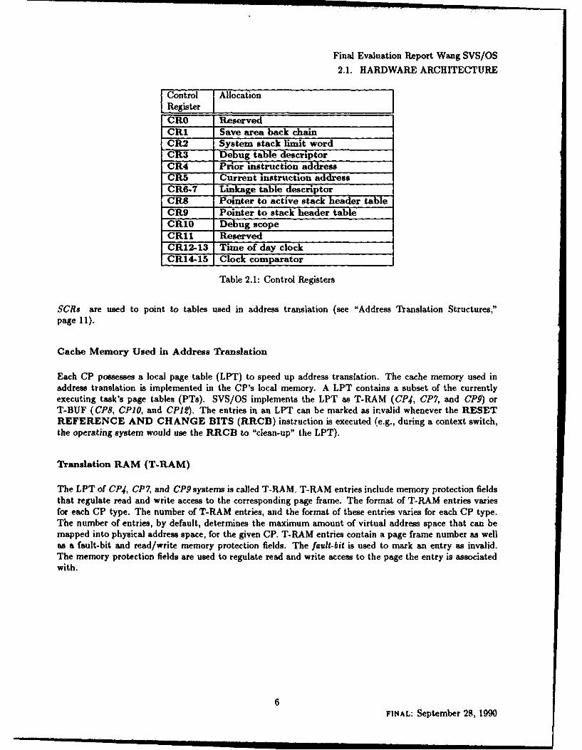
Control Registers provide storage for manipulation of the program control information not contained in thePCW. These registers are identified as CR0 through CR15 (see Table 2.1).
Unprivileged users may modify only CR1 through the use of the following instructions.
" JUMP TO SUBROUTINE ON CONDITION INDIRECT (JSCI);
* RETURN ON CONDITION (RTC);
" RETURN AND POP ON CONDITION (RPC);
" SUPERVISOR CALL (SVC).
JSCI provides the mechanism for branching to the entry point of a subroutine. With this instruction thesubroutine executes with the caller's context, but could potentially be executing in a different hardwaredomain (i.e., ring). RTC and RPC return to the location immediately after the branch made by the JSCIinstruction.
SVC provides the mechanism for branching to the entry point of a supervisor call. With this instructionthe caller's context is saved, the subroutine executes with hardware privilege, and the subroutine couldpotentially be executing in a different ring. SVCX (which is privileged) returns to the location immediatelyafter the supervisor call, after it restores the caller's context (including whatever privilege the caller mayhave had).
When information is loaded into the control registers, no check is made to determine the validity of theinformation. The check is made whenever the information is referenced. Hence, an invalid address could beloaded into a control register, but an error would occur when an attempt is made to use that address.
5FINAL: September 28, 1990
Final Evaluation Report Wang SVS/OS2.1. HARDWARE ARCHITECTURE
Control AllocationRegister IICR0 ReservedCR1 Save area back chainCR2 System stack limit wordCR3 Debug table descriptorCR4 Prior instruction addressCR5 Current instruction addressCR67 Linkage table descriptorCR8 Pointer to active stack header tableCR9 Pointer to stack header tableCR10 Debug scopeCR1 ReservedCR12-13 Time of day clockCR14-15 Clock comparator
Table 2.1: Control Registers
SCRs are used to point to tables used in address translation (see "Address Translation Structures,"page 11).
Cache Memory Used in Address Translation
Each CP possesses a local page table (LPT) to speed up address translation. The cache memory used inaddress translation is implemented in the CP's local memory. A LPT contains a subset of the currentlyexecuting task's page tables (PTs). SVS/OS implements the LPT as T-RAM (CP4, CP7, and CP9) orT-BUF (CP8, CPIO, and CPI2). The entries in an LPT can be marked as invalid whenever the RESETREFERENCE AND CHANGE BITS (RRCB) instruction is executed (e.g., during a context switch,the operating system would use the RRCB to "clean-up" the LPT).
Translation RAM (T-RAM)
The LPT of CP4, CP7, and CP9 systems is called T-RAM. T-RAM entries include memory protection fieldsthat regulate read and write access to the corresponding page frame. The format of T-RAM entries variesfor each CP type. The number of T-RAM entries, and the format of these entries varies for each CP type.The number of entries, by default, determines the maximum amount of virtual address space that can bemapped into physical address space, for the given CP. T-RAM entries contain a page frame number as wellas a fault-bit and read/write memory protection fields. The fault-bit is used to mark an entry as invalid.The memory protection fields are used to regulate read and write access to the page the entry is associatedwith.
6FINAL: September 28, 1990
Final Evaluation Report Wang SVS/OS
2.1. HARDWARE ARCHITECTURE
Translation Buffer (T-BUF)
The LPT of CP8, CPO, and CP12 systems is called T-BUF. T-BUF is also CP-local RAM and is used tostore address translations T-BUF provides the same functions as T-RAM, but is a different implementationused in the newer CP types. It allows multiple virtual pages to be mapped into one T-BUF entry (i.e., eightmappings). Clearing of the T-BUF is based on a monitor bit and fault-bit. The RRCB instruction setsthe fault-bit to signify that the given T-BUF entry is invalid. The monitor bit is used for selective clearingof the T-BUF. As with T-RAM, T-BUF also supports read/write protection fields used to determine how apage may be accessed.
Reference and Change Table (RCT)
The RCT is located in CP-local RAM and provides an area to keep track of page changes and page references.There is a 2-bit RCT entry associated with each physical page frame of main memory. A page frame is 2048contiguous bytes (2 KB) of physical memory beginning on a 2 KB boundary. The two bits in the RCT areused to record references or modifications to the given page in memory. RCT entries are cleared by theRRCB instruction. When RRCB is executed, the RCT entry for a page frame is tested and then cleared.
Arithmetic and Logic Unit (ALU)
The ALU supports the CP by providing mechanisms to perform fixed-point, floating-point, decimal, anddecimal-floating-point arithmetic, as well as basic logical operations.
Clock
The time-of-day clock is a 64-bit binary counter located on the CP. System time is kept by incrementingthis binary counter.2 The clock value is stored in CR12 and CR13 which are initialized to zero on systempower-up. The clock will continue to run as long as it is supplied with power.
Associated with the clock is the clock comparator. It provides a means of causing an interruption when theclock has passed a value specified by a given program (i.e., whenever the clock and clock comparator areequal). The clock comparator is also a 64-bit entity stored in CR14 and CR15.
CP Instructions
The CP provides instructions to perform arithmetic and logical operations. An instruction is from one tofour half-words in length and has one of nine basic addressing formats.
The instruction set supports over 220 instructions; a detailed description of these instructions can be foundin the VS Principles of Operation [27]. There are five general categories of instructions: arithmetic, logical,stack related, miscellaneous, and privileged. Miscellaneous instructions include those used for debugging andother special purposes.
2The resolution of the clock, and the rate at which the counter ias stepped, is dependent on both the CP type and the linevoltage frequency.
7FINAL: September 28, 1990
Final Evaluation Report Wang SVS/OS
2.1. HARDWARE ARCHITECTURE
Program Control Word (PCW)
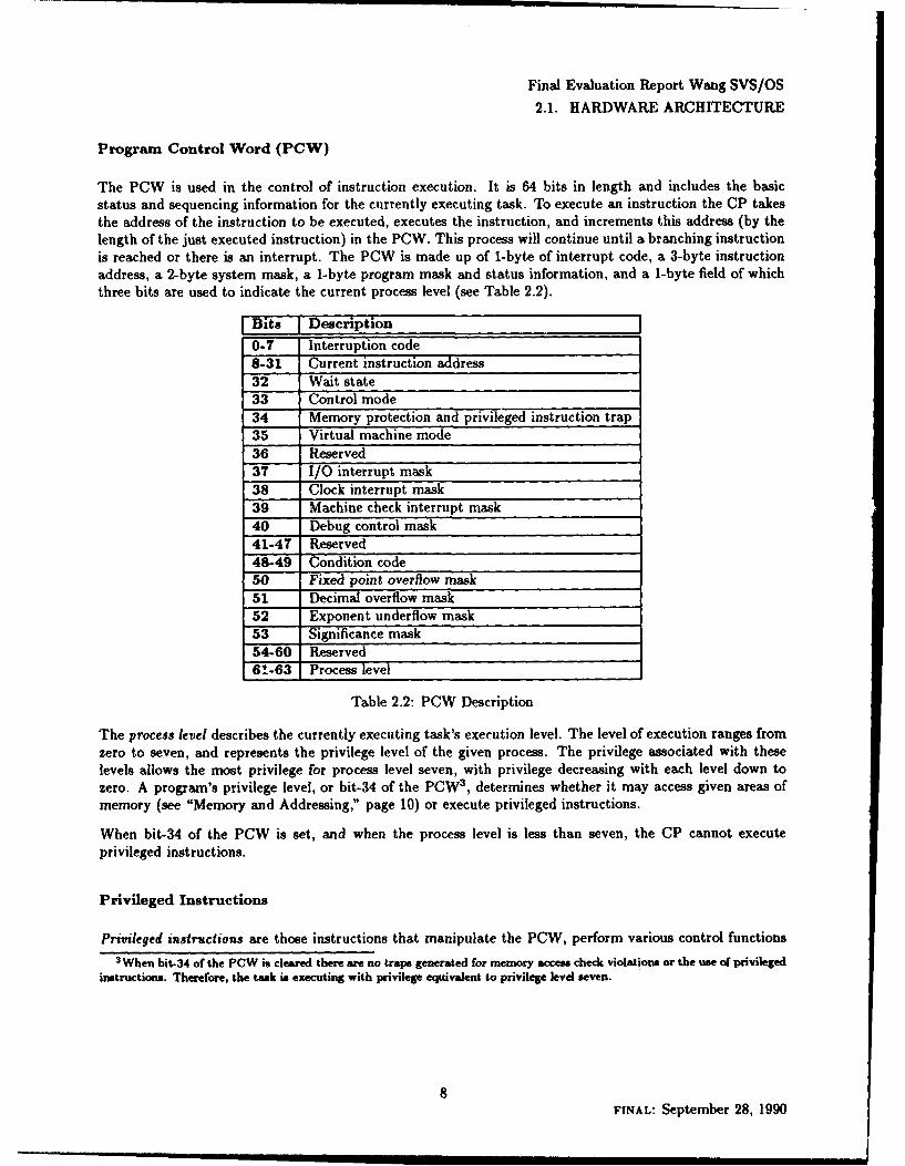
The PCW is used in the control of instruction execution. It is 64 bits in length and includes the basicstatus and sequencing information for the currently executing task. To execute an instruction the CP takesthe address of the instruction to be executed, executes the instruction, and increments this address (by thelength of the just executed instruction) in the PCW. This process will continue until a branching instructionis reached or there is an interrupt. The PCW is made up of 1-byte of interrupt code, a 3-byte instructionaddress, a 2-byte system mask, a 1-byte program mask and status information, and a 1-byte field of whichthree bits are used to indicate the current process level (see Table 2.2).
Bits I Description
0-7 Interruption code8-31 Current instruction address32 Wait state33 Control mode34 Memory protection and privileged instruction trap35 Virtual machine mode36 Reserved37 I/O interrupt mask38 Clock interrupt mask39 Machine check interrupt mask40 Debug control mask41-47 Reserved48-49 Condition code50 Fixed point overflow mask51 Decimal overflow mask52 Exponent underflow mask53 Significance mask54-60 Reserved-6!63 Process level
Table 2.2: PCW Description
The process level describes the currently executing task's execution level. The level of execution ranges fromzero to seven, and represents the privilege level of the given process. The privilege associated with theselevels allows the most privilege for process level seven, with privilege decreasing with each level down tozero. A program's privilege level, or bit-34 of the PCW3 , determines whether it may access given areas ofmemory (see "Memory and Addressing," page 10) or execute privileged instructions.
When bit-34 of the PCW is set, and when the process level is less than seven, the CP cannot executeprivileged instructions.
Privileged Instructions
Privileged instructions are those instructions that manipulate the PCW, perform various control functions3 When bit-34 of the PCW is cleared there are no traps generated for memory access check violations or the use of privileged
instructions. Therefore, the task is executing with privilege equivalent to privilege level seven.
8FINAL: September 28, 1990
Final Evaluation Report Wang SVS/OS2.1. HARDWARE ARCHITECTURE
(e.g., RRCB), are relevant to address translation, or control I/O. These instructions are considered to beprivileged because of the type of actions they perform. Only programs of process level seven, or those withbit-34 of the PCW cleared, can execute privileged instructions.
For a complete description of the privileged instructions see the VS Principles of Operation [27].
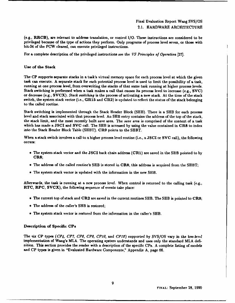
Use of the Stack
The CP supports separate stacks in a task's virtual memory space for each process level at which the giventask can execute. A separate stack for each potential process level is used to limit the possibility of a task,running at one process level, from overwriting the stacks of that same task running at higher process levels.Stack switching is performed when a task makes a call that causes its process level to increase (e.g., SVC)or decrease (e.g., SVCX). Stack switching is the process of activating a new stack. At the time of the stackswitch, the system stack vector (i.e., GR15 and CR2) is updated to reflect the status of the stack belongingto the called routine.
Stack switching is implemented through the Stack Header Block (SHB). There is a SHB for each processlevel and stack associated with that process level. An SHB entry contains the address of the top of the stack,the stack limit, and the most recently built save area. The save area is comprised of the context of a taskwhich has made a JSCI and SVC call. The SHB is accessed by using the value contained in CR8 to indexinto the Stack Header Block Table (SHBT). CR9 points to the SHBT.
When a stack switch involves a call to a higher process level routine (i.e., a JSCI or SVC call), the followingoccurs:
* The system stack vector and the JSCI back chain address (CR1) are saved in the SHB pointed to by
CR8;
" The address of the called routine's SHB is stored in CR8; this address is acquired from the SHBT;
" The system stack vector is updated with the information in the new SHB.
Afterwards, the task is running at a new process level. When control is returned to the calling task (e.g.,RTC, RPC, SVCX), the following sequence of events take place:
" The current top of stack and CR2 are saved in the current routines SHB. The SHB is pointed to CR8;
* The address of the caller's SHB is restored;
" The system stack vector is restored from the information in the caller's SHB.
Description of Specific CPs
The six CP types (CP4, CP7, CPS, CP9, CP10, and CPI2) supported by SVS/OS vary in the low-levelimplementation of Wang's MLA. The operating system understands and uses only the standard MLA defi-nition. This section provides the reader with a description of the specific CPs. A complete listing of modelsand CP types is given in "Evaluated Hardware Components," Appendix A, page 66.
9FINAL: September 28, 1990
Final Evaluation Report Wang SVS/OS
2.1. HARDWARE ARCHITECTURE
The CP4 uses a T-RAM for LPTs, and interfaces with devices through Bus Adaptors (BAs) in combinationwith I/O Processors (lOPs).
The CP7 employs T-RAM and uses high speed caches and virtual addresses at the microcode level toimprove performance. CP7s interface with devices through Bus Processors (BPs) in combination withDevice Adapters (DAs).
The CP8s, CP1Os, and CP12s provide the greatest I/O capacities as well as the largest main memory andI/O configuration potential. They interface with devices through microcode-load able I/O Controllers, useT-BUF for LPTs, and have support for a Support Control Unit (SCU) [59]).
CP10s and CPI2s are essentially identical to CP8s with increased performance. This performance increaseis due to the CP10 being based on ECL technology and the CP12 being based on CMOS technology. Theresulting hardware differences are handled by the microcode, as is the case with all other CP types.
The CP9 provides high I/O capacities and memory options spanning from 2 MB to 16 MB. They interfacewith devices through programmable I/O Coprocessors 4 and use T-RAM for address translation support.Each I/O Coprocessor interfaces with the system bus through its own Bus Interface Controller (BIC). BICssend messages between processors and, during I/O, perform direct memory access between main memoryand 1/0 Coprocessors.
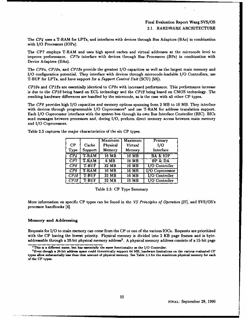
Table 2.3 captures the major characteristics of the six CP types.
Maximum Maximum Primary
CP Cache Physical Virtual I/OType Support Memory Memory InterfaceCP4 T-RAM 16 MB 16 MB BA & lOPCP7 T-RAM 8 MB 16 MB BP & DACP8 T-BUF 32 MB 16 MB I/O ControllerCP9 T-RAM 16 MB 16 MB I/O CoprocessorCP10 T-BUF 32 MB 16 MB I/O ControllerCPI2 T-BUF 32 MB 16 MB I/O Controller
Table 2.3: CP Type Summary
More information on specific CP types can be found in the VS Principles of Operation [27], and SVS/OS'sprocessor handbooks [4].
Memory and Addressing
Requests for I/O to main memory can come from the CP or one of the various IOCs. Requests are prioritizedwith the CP having the lowest priority. Physical memory is divided into 2 KB page frames and is byte-addressable through a 26-bit physical memory address'. A physical memory address consists of a 15-bit page
4 This is a different name, but has essentially the same functionality as the I/O Controller.sEven though a 26-bit address space could theoretically support 64 MB, hardware limitations on the various evaluated CP
types allow substantially less than that amount of physical memory. See Table 2.3 for the maximum physical memory for eachof the CP types,
10FINAL: September 28, 1990
Final Evaluation Report Wang SVS/OS
2.1. HARDWARE ARCHITECTURE
frame address, and an 11-bit offset into the given page frame. The range of addressable physical memorydepends on the amount of memory for the given CP configuration and ranges from 512 KB to 32 MB.
There is a physical page frame table with an entry for every physical page. Each entry contains informationsuch as the amount of time since last used, whether the page has been modified, file location and usage block(FLUB 6 ) pointer, etc.
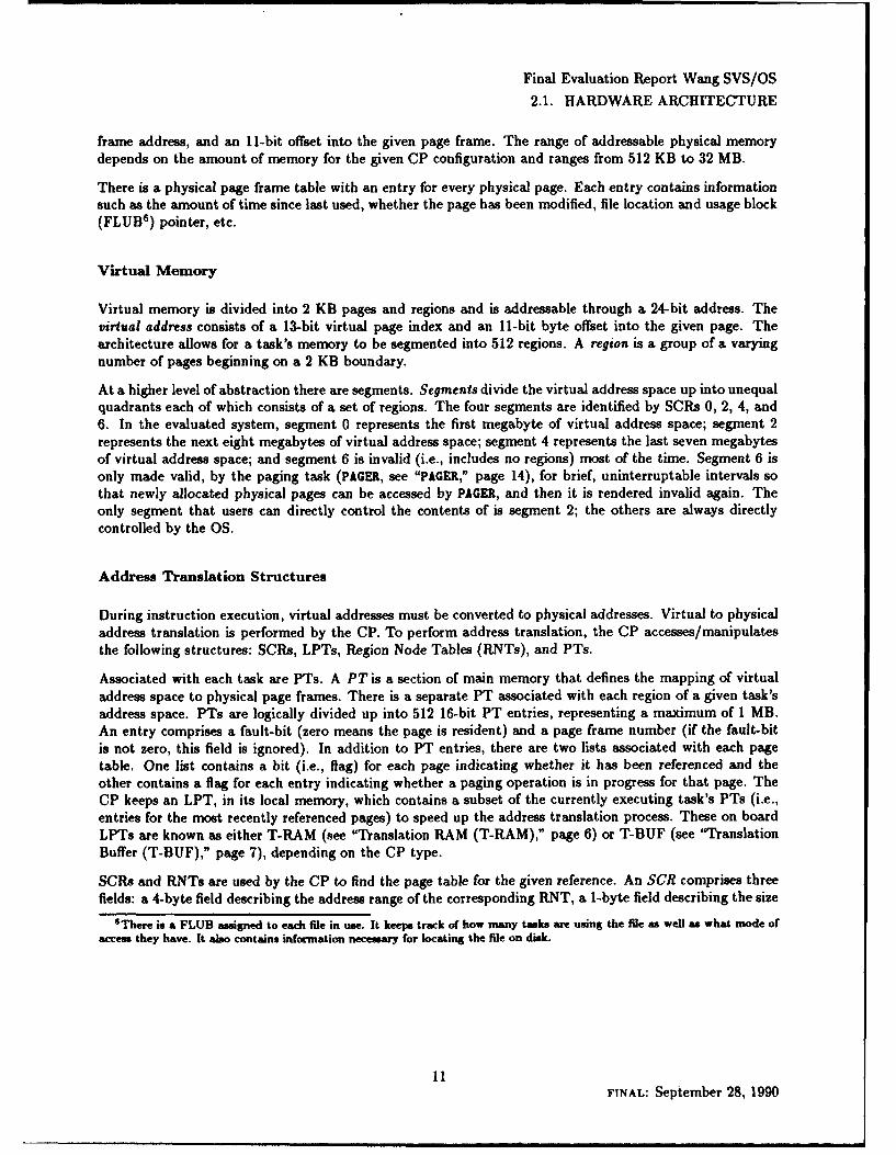
Virtual Memory
Virtual memory is divided into 2 KB pages and regions and is addressable through a 24-bit address. Thevirtual address consists of a 13-bit virtual page index and an 11-bit byte offset into the given page. Thearchitecture allows for a task's memory to be segmented into 512 regions. A region is a group of a varyingnumber of pages beginning on a 2 KB boundary.
At a higher level of abstraction there are segments. Segments divide the virtual address space up into unequalquadrants each of which consists of a set of regions. The four segments are identified by SCRs 0, 2, 4, and6. In the evaluated system, segment 0 represents the first megabyte of virtual address space; segment 2represents the next eight megabytes of virtual address space; segment 4 represents the last seven megabytesof virtual address space; and segment 6 is invalid (i.e., includes no regions) most of the time. Segment 6 isonly made valid, by the paging task (PAGER, see "PAGER," page 14), for brief, uninterruptable intervals sothat newly allocated physical pages can be accessed by PAGER, and then it is rendered invalid again. Theonly segment that users can directly control the contents of is segment 2; the others are always directlycontrolled by the OS.
Address Translation Structures
During instruction execution, virtual addresses must be converted to physical addresses. Virtual to physicaladdress translation is performed by the CP. To perform address translation, the CP accesses/manipulatesthe following structures: SCRs, LPTs, Region Node Tables (RNTs), and PTs.
Associated with each task are PTs. A PT is a section of main memory that defines the mapping of virtualaddress space to physical page frames. There is a separate PT associated with each region of a given task'saddress space. PTs are logically divided up into 512 16-bit PT entries, representing a maximum of 1 MB.An entry comprises a fault-bit (zero means the page is resident) and a page frame number (if the fault-bitis not zero, this field is ignored). In addition to PT entries, there are two lists associated with each pagetable. One list contains a bit (i.e., flag) for each page indicating whether it has been referenced and theother contains a flag for each entry indicating whether a paging operation is in progress for that page. TheCP keeps an LPT, in its local memory, which contains a subset of the currently executing task's PTs (i.e.,entries for the most recently referenced pages) to speed up the address translation process. These on boardLPTs are known as either T-RAM (see "Translation RAM (T-RAM)," page 6) or T-BUF (see "TranslationBuffer (T-BUF)," page 7), depending on the CP type.
SCRs and RNTs are used by the CP to find the page table for the given reference. An SCR comprises threefields: a 4-byte field describing the address range of the corresponding RNT, a 1-byte field describing the size
6 There is a FLUB assigned to each file in use. It keeps track of how many tasks are using the file as well as what mode ofaccess they have. It also contains information necessary for locating the file on disk.
1mFINAL: September 28, 1990

Final Evaluation Report Wang SVS/OS
2.1. HARDWARE ARCHITECTURE
of the corresponding RNT, and a 3-byte field giving the physical address of the RNT 7 . The RNT addressrange is described in terms of two 2-byte fields representing the lowest and highest virtual pages included inthe RNT.
An RNT consists of I to 128 16-byte entries known as region nodes. Each region node describes a region andpoints to the LPT for that region. The CP references only the first eight bytes of the region node; the othereight bytes are available for use by the operating system. The portion of a region node used by the CP islogically divided into three fields: the first 4-byte field describes the address range of the region, the next1-byte field specifies control and access information about the pages in the region, and the next 3-byte fieldgives the physical address of the PT for the given region. The region address range is described in terms oftwo 2-byte fields representing the lowest and highest virtual pages included in the region. Two sub-fields ofthe control and access field are of particular interest; these fields define the minimum read and write accesslevels for all the pages in the given region (see "Memory Protection," page 14).
The eight bytes of each region node that are not used directly by the CP contain a pointer to a FLUB andan offset indicating where in the file that the region begins. This information is used by PAGER to determinewhere to read pages from and where to write them to. Note that if a file is larger than 1 MB (i.e., the PTlimit), it is divided into multiple regions. Each region node will have its own PT, but will point to the sameFLUB (but will have different offsets).
Address Translation Procedure
The address translation process begins when the CP references its LPT. If the entry corresponding to thevirtual page is found in the LPT, is valid, and the requesting task has the proper access permissions (theLPT entry includes read and write access information), the respective physical address is generated byconcatenating the 15-bit physical page frame number in the LPT and the 11-bit byte offset in the virtualaddress. If there is not a valid entry corresponding to the requested address in the LPT, the CP mustperform a complete address translation. If the corresponding entry is valid but the access check fails, aprogram check is generated and access is denied.
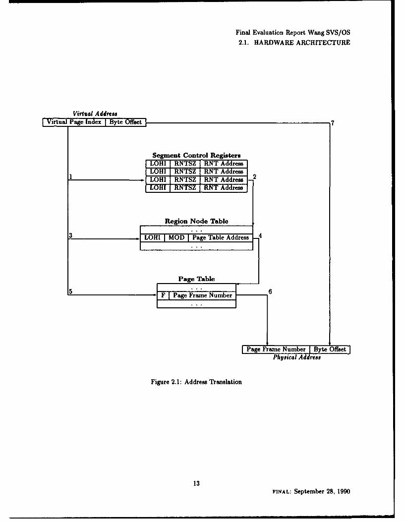
Using numbers to refer to corresponding points in Figure 2.1, the process is as follows.
(1) The virtual page index is compared against the virtual page range defined by the "LOHI" field in theSCRs to find the first segment that contains the virtual page. The SCRs from SCR 0 to SCR 6 will bechecked until a match is found or all SCRs have been examined. If the virtual page is not found within oneof the SCR defined segments, a program check is generated and access is denied.
(2) The SCR, found in procedure (1) above, is then used to determine the physical address and size (i.e.,"RNTSZ") of the corresponding RNT.
(3) The virtual page index is then compared against the virtual page range defined by the "LOHI" field ofeach region node in the RNT to find the first region that contains the virtual page. The region nodes arechecked sequentially until a match is found or all region nodes have been examined. If the virtual page isnot found within one of the region node defined regions, a program check is generated and access is denied.
(4) The RNT entry, found in procedure (3) above, is then used first to make an access check using the"MOD" field (see "Memory Protection," page 14). If the access check passes, the region node is then usedto determine the physical address of the corresponding PT.
TAn alternate format for the SCRs in used by PAGER to allow it special access necessary for performing pagng operations.
12FINAL: September 28, 1990
Final Evaluation Report Wang SVS/OS2.1. HARDWARE ARCHITECTURE
Virtual AddressVirtal ageInde Bye 07
Segment Control RtegistersLOHl I RNTSZ [RNT AddressLOHI RNTSZ R-NT A ress
ILOHI IRNTSZ RNT Address 2HIl RNT Z RNTAddress
Region Node Table
ILOHI I MOD I Page Table Address
Page Table
F Pge rame Number
Page Frame Number Byte OffsetPhysical Address
Figure 2.1: Address Translation
13FINAL: September 28, 1990

Final Evaluation Report Wang SVS/OS2.1. HARDWARE ARCHITECTURE
(5) The CP then accesses the given PT using an index computed from the virtual page index and the lowestvirtual page in the PT (i.e., "LO" from the region node) to find the relevant PT entry. Note that whileSCRs and RNTs could have gaps, rendering some of the virtual pages invalid, PTs must consist of contiguouspages.
(6) From the PT entry, the CP can determine whether the given page is valid using the "F" field. If it isnot resident, an interrupt occurs and PAGER takes over.
(7) If the page is resident, the byte offset from the virtual address is concatenated with the page framenumber, and the physical address is returned.
The result (i.e., physical page frame number and access information for the given virtual page) from thisaddress translation is then cached in the LPT for use in future address translations.
PAGER
If a virtual page is found to be nonresident, PAGER has to map it to a physical page frame and, possibly, findthe given page in a file and load it into memory. This task is privileged and runs with the highest priority.
PAGER keeps track of the fact that it is processing a page fault on a given page so that multiple page faultson the same page are only handled once. It also determines whether the faulted page has been used, and istherefore mapped to a file. If it is not mapped to a file, PAGER simply finds a physical page frame and mapsthe virtual page to it. If it is mapped to a file, PAGER must then go into the FLUB, which is pointed to bythe region node, and determine where the file is as well as the file offset. It can then move the appropriatepage into memory from the file.
When PAGER cannot find any free physical page frames, it must make a determination (based on age)regarding which page to swap out. Once PAGER finds a page to swap out, it determines whether it has beenmodified since it has been brought into memory. If has been modified then it is written out to disk using theFLUB (associated with that physical page frame). Next, also using the FLUB, PAGER locates the PT entrythat is currently mapped to that physical page frame in invalidates it. Now PAGER is able to map the virtualaddress currently being accessed to this now free physical page frame.
Shared Memory
Whenever a file (e.g., a program) is mapped into multiple tasks' address spaces, there is a single PT createdfor that file. There is also only a single FLUB for that file. However, each task still has its own unique RNT.
Each tasks' RNT will point both to the same FLUB and PT. Within the FLUB, there is informationindicating such things as how many tasks are currently using the file and what modes of access are allowed(i.e., certain modes of access require exclusive use of the file). The PT will continue to exist until no task isusing that file.
Memory Protection
SVS/OS supports region based read and write memory protection. Associated with every region of virtualaddress space is an access level. An access level is represented by a number from zero to seven, where zero
14FINAL: September 28, 1990

Final Evaluation Report Wang SVS/OS
2.1. HARDWARE ARCHITECTURE
is the least privileged and seven is the most privileged. Access to a region is determined by a task's currentprocess level. A task running at a given process level can access any region of memory assigned an accesslevel less than or equal to the task's process level.
Access levels are defined separately for read and write access. Included in the entries of the region nodetable are sub-fields that define the minimum access level required to read and write each individual memoryregion it describes. These fields are not modifiable by unprivileged users. During address translation, thevalues associated with these sub-fields are compared with the executing task's current process level (i.e., theprocess level specified in the PCW). If the task's process level is greater than or equal to the region's definedaccess level, access to that region is granted. Otherwise, a program check is generated and access is denied.Access level memory protection can be overridden if the given task's PCW bit-34 is not set, indicating it isprivileged.
lOCs
IOCs serve as an interface between the CP and various I/O devices. An IOC provides a generic base todescribe the SVS/OS I/O architecture; other specific devices will be covered at the end of this section (e.g.,BAs, BPs, IOPs, and I/O Controllers).
IOCs execute concurrently with the CP; they are capable of accessing main memory, communicating withdevices, and provide the overall support for controlling I/O devices. The structures that allow the CP tointerface with the TOCs are the I/O Status Table (IOST), and the I/O Command Table (IOCT).
The IOST is used by the IOC to store the I/O completion status of a given I/O operation. The IOST ismade up of 16-byte entries; two important fields in these entries are the I/O Status Word (IOSW), andthe Command Table Address (CTA). Information is stored in a given IOSW by an IOC prior to the IOCnotifying the CP of completion (via an interrupt). CTA entries point to the IOCT for the IOC associatedwith the given I/O operation.
There is an IOCT associated with each TOC; it is made up of 16-byte fields (one for each device on thegiven system). Each entry comprises two fields: an I/O Command Word (IOCW), and a Unit Control BlockAddress (UCBA). The IOCW specifies the command that is to be executed and is made up of a commandcode, a data address, and the data length.
I/O Instructions
The basic assembler instructions for I/O are: Start I/O (SIO), Control I/O (CIO), and Halt I/O(HIO). SIO is used to initiate a transfer between memory and a specified device. CIO is used to initiatecontrol operations on a given device. HIO is used to halt an SIO or CIO request. These three instructionsare privileged. Before the CP executes an I/O instruction, it stores command information in the IOCWand notifies the appropriate IOC. The IOC will request service from the given device and wait until therequest is acknowledged. On completion, the IOC will update the appropriate IOSW and notify the CP ofthe completion.
15FINAL: September 28, 1990

Final Evaluation Report Wang SVS/OS2.1. HARDWARE ARCHITECTURE
Bus Adaptors
A BA (see Figure 2.2) is an interface device that provides a mechanism for a CP to communicate with oneor more IOPs through the system's 1/0 bus. The BA maintains a pair of registers for I/O between the CPand IOPs. It is used as an intermediary by the CP; communication takes place by the CP sending the BAa message that identifies the desired operation and IOP. The BA will ascertain whether the given lOP isready to process. If it is ready to process the request the BA passes the message to it. The BA then returnsthe status to the CP.
Bus Processors and Device Adaptors
A BP (see figure 2.3) performs as an IOC that communicates with a DA. The BP communicates directlywith the CP and the DA. The DA provides the functionality to talk to a given device. The BP and DA pairhandle all communication between the CP and the devices.
Input/Output Processors
An lOP (see Figure 2.2) is an IOC that provides an interface to a given device and the CP. An lOP is aProgrammable Read-only Memory (PROM)-based device. All of its control logic is permanently loaded, inPROM chips, on the interface board.
Input/Output Controllers
An I/O Controller (see Figure 2.4) is an IOC that provides a connection from a CP to a given device. It issimilar in function to an IOP, but does not support PROM-based control logic. Instead, an I/O Controller isprogrammable and is loaded with its controlling microcode (see "System Initialization," page 39) at InitialProgram Load (IPL). All I/O Controllers are implemented on a private, high-speed I/O bus which interfacesto the system bus through a System Bus Interface (SBI).
Inplit/Output Coprocessors
An I/O Coprocessor (see Figure 2.5), which has essentially the same function as an I/O Controller, requiresa special interface device (i.e., BIC) since it interfaces directly to the system bus (i.e., there is no local I/Obus). Each BIC supports its I/O Coprocessor with DMA, Interconnect, I/O space, and Message passingoperations.
Use of IOCs
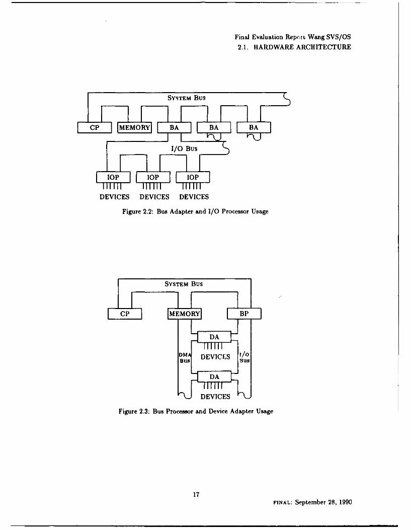
Figure 2.2 shows the interactions of the BA and three IOPs. The BA is directly connected to the systembus. The BA provides a local I/O bus, to which the various IOPs are connected. The devices are connectedto the lOPs.
16FINAL: September 28, 1990
Final Evaluation Repcrt Wang SVS/OS
2.1. HARDWARE ARCHITECTURE
SYSTEM Bus
CP MEMORY BA BA BA
I lo lMop¥1 lop
DEVICES DEVICES DEVICES
Figure 2.2: Bus Adapter and I/O Processor Usage
SYSTEM Bus
CP MEMORY BP
DA
DM DEVICES //oiBusY BUS
DA
DEVICES
Figure 2.3: Bus Processor and Device Adapter Usage
17FINAL: September 28, 1990
Final Evaluation Report Wang SVS/OS2.1. HARDWARE ARCHITECTURE
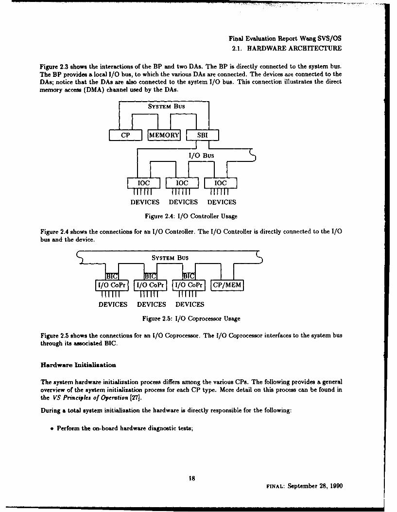
Figure 2.3 shows the interactions of the BP and two DAs. The BP is directly connected to the system bus.The BP provides a local I/O bus, to which the various DAs are connected. The devices are connected to theDAs; notice that the DAs are also connected to the system I/O bus. This connection illustrates the directmemory access (DMA) channel used by the DAs.
SYSTEM Bus
CP MEMORY SBI
1/0 Bus
I c 1o0 , CoDEVICES DEVICES DEVICES
Figure 2.4: I/O Controller Usage
Figure 2.4 shows the connections for an 1/0 Controller. The I/O Controller is directly connected to the I/Obus and the device.
SYSTEM Bus
1/0 CoPr 1/O CoPr 0/ CoPr OP/MEM
DEVICES DEVICES DEVICES
Figure 2.5: 1/0 Coprocessor Usage
Figure 2.5 shows the connections for an I/O Coprocessor. The I/O Coprocessor interfaces to the system busthrough its associated BIC.
Hardware Initialisation
The system hardware initialization process differs among the various CPs. The following provides a generaloverview of the system initialization process for each CP type. More detail on this process can be found inthe VS Principles of Operation [27].
During a total system initialization the hardware is directly responsible for the following:
* Perform the on-board hardware diagnostic tests;
18FINAL: September 28, 1990

Final Evaluation Report Wang SVS/OS
2.1. HARDWARE ARCHITECTURE
" Load the CP with its controlling microcode;
" Initialize main memory.
Hardware diagnostics provide a means for the system to ensure that its components are working properlybefore it begins the initialization process (see "Hardware Diagnostics," page 23). The CP microcode isloaded into the CP's local control store, providing it with its microinstruction set. The clearing of memoryis required because the system cannot determine the state of the machine prior to initialization. Since itrequires a known memory state, the entire memory is overwritten at this time. Once these three steps havebeen accomplished, the software takes over.
The CP4 systems are initialized via a PROM-based IOP. The CP microcode is loaded from the IPL device(i.e., a local disk drive which is designated for this purpose). IPL is achieved by loading the microcode fromthe local disk and pressing the boot strap button on the system front panel. This leaves the machine in controlmode (see "Control Mode," page 32). Load commands are used, from the system console (Workstation 0),to initiate the loading of the software, to specify the BA, the port of the IPL device, and lOP.
The CP7 systems do not support any load commands. Loading of the microcode is accomplished by manuallyselecting the diagnostic IPL device that provides a mechanism to select the IPL boot device. Microcodeloading is performed from Workstation 0 via a menu driven application program. The BP controls IPL upto the point when Control Mode is reached.
The CP8, CP10, and CP12 systems are initialized from a Wang Personal Computer (PC)-based SCU. Byturning on the SCU, the system is initialized and left in Control Mode.
The CP9 systems are initialized from Workstation 0, which is attached to the system bus through a special,non-optional I/O Coprocessor known as a Resource Control Unit (RCU). The RCU orchestrates the IPLprocess, loading the operational and CPU microcode required for system generation: this includes bothboot-up and diagnostic software.
Support Control Unit
The SCU consists of the system panel and the workstation that is cabled as device 0 on port 0. For CP8,CPIO, and CP12 processors, the SCU is the "System Console." The operator can cause the CP to enterControl Mode manually by using the SCU (CP8, CPID, and CP12 systems only) or the Control Mode buttonon other CP systems. The ability to enter control mode can be controlled by a key lock on all CPs, exceptCP4.
The SCU is a 16-bit microprocessor-based unit with a built-in 5 inch diskette drive and a fixed-disk drive.The SCU serves as Workstation 0, and can also function as a conventional workstation. The SCU has directaccess to the CP8, CPO, or CPI2 processor, independent of the system bus, thereby allowing it to accessthe system even if there are malfunctions of major system elements.8
The SCU can perform the following functions:
* microcode and diagnostic code loading;6The SCU runs a special applications software package known as SYSCON. SYSCON, written by Wang, runs on a stripped-down
version of MS-DOS, and is supplied with the SCU.
19FINAL: September 28, 1990
Final Evaluation Report Wang SVS/OS
2.1. HARDWARE ARCHITECTURE
" initial program load (IPL);
* memory dump operations;
" local and remote9 maintenance, including hardware and software support;
" standard workstation operations.
2.1.2 Devices
The Wang VS Product Family supports four types of devices: workstations, printers, disks and tapes. Formore detail refer to the VS Principles of Operation [27]. The evaluated configuration consists only of devicesthat are directly connected to the host system.
In general, all devices communicate using an IOCW from the CP to the device and an IOSW from thedevice to the CP. The system supports indirect addressing through a data address which points to a list ofaddresses of buffers to be used in the data transfer.
IOCs are loaded with microcode, by the operating system, via the LOADCODE SVC. This interface downloadsa microcode image file that provides a controller with its micro-instruction set. The loading of this microcodetakes place at system initialization (see "System Initialization," page 39) or when requested by an authorizeduser (e.g., operator). During system initialization all I/O devices are reset; a reset causes the device toterminate all ongoing operations, and wait for its microcode. The system will generate a process, QIOSLOAD,which reads the configuration file that specifies the list of system devices (i.e., GCOIFIG*). From this list thelocation of the microcode image files for t'ie given IOC, and the appropriate control parameters (e.g., buslocation, transfer locations) are determined. Once this information has been determined, QIOSLOAD loads allIOCs with the appropriate microcode image and control parameters.
Workstations
SVS/OS supports workstations with either 24 or 25 lines of 80 characters each. Refer to "Workstations,"Appendix A.3.3, page 74, for a complete list of supported workstations. Line 25 is supported on many of theworkstations. This line is a message/status line that can be used by an application program to communicateapplication dependent information to the user at the workstation. All supported workstations conform to acommon architecture that is described in the following paragraphs.
The workstation keyboard, called the "Wang Universal Keyboard" has a multitude of keys for data entry,cursor positioning, system communication, and other special purpose keys.
These workstations support the ASCII standard character set as well as the FIPS-15 95-character subsetstandard (61]. The workstation screen can be formatted into distinct fields, each having a distinct set ofattributes. The attributes control the display form and intensity of a field, and the ability of the user tomodify it.
The buffer area specified on an I/O transfer is called a data area and is made up of a 4-byte order areaand a mapping area. The order area contains control information (i.e., screen location). The mapping areacontains the data and field attribute characters.
'Since remote maintenance requires connecting the SCU to a phone line, it is not considered part of the evaluatedconfiuration.
20FINAL: September 28, 1990

Final Evaluation Report Wang SVS/OS
2.1. HARDWARE ARCHITECTURE
The workstations support the following commands:
" READ - copy specified part of screen to the mapping area and store the cursor position in the orderareal°;
" READ ALTERED - read fields that have the selected-fields tags set into the mapping area;
" READ DIAGNOSTIC - same as the READ command except that it does not affect special fieldson the screen (i.e., pseudo-blanks are not converted, field attributes are left unchanged, and the cursorposition is left unchanged);
" READ TABS - read the column numbers of all the set tabs (up to ten);
" WRITE - transfer the data from the mapping area to the screen;
" WRITE SELECTED - transfer from the mapping area those fields that have the selected-field tagsset to the screen;
* WRITE TABS - causes all tabs to be cleared and then sets up to ten tabs as specified from themapping area.
When a workstation is powered on, an attention interrupt is generated and the system responds by loadingthe microcode for that workstation. Refer to "System Initialization," page 39, for more information on thedetails of this process. Additionally, microcode can be subsequently loaded from SVS/OS to the workstationat any time. This allows users to customize the "personality" of the workstation, and SVS/OS to restorethe system default microcode when workstation ownership changes. 11
Printers
SVS/OS supports a full range of printers. Refer to "Printers," Appendix A.3.4, page 74, for a complete listof supported printers.
Data transfer is based on variable length blocks of up to 2 KBs. The following block types are supported:
" PRINT DATA BLOCK - contains records to be printed;
" PRINT CONTROL DATA BLOCK - contains records used for controlling the printing of printdata blocks (e.g., vertical and horizontal pitch, form length and printer speed);
* FONT DATA BLOCK - contains font files. The default font is loaded into the printer when thesystem is initialized or when the device is powered on. Other fonts may be loaded in response to arequest from the application using the printer;
o IPL CODE OVERLAY BLOCK - contain overlays of printer microcode. One overlay is loadedinto the printer when the system is initialized or when the device is powered on. Other overlays maybe loaded later in response to a request for a special function from the application using the printer.
1°The READ includes converting pseudo-blanks to real blanks and changing blinking fields, of the screen, to high-intensity.
I ISince the TCB depends upon some of the functions of such workstations to enfore its security policies (e.g., object reuse),it is necessary that these workstations be protected from unauthorized tampering or modification.
21FINAL: September 28, 1990

Final Evaluation Report Wang SVS/OS
2.1. HARDWARE ARCHITECTURE
All systems support font and IPL code overlays. On power up, after the microcode is loaded, the printerwill request the font and IPL code overlays in a IOSW. For more information on this process see "SystemInitialization," page 39. The complete protocols for the printers can be found in the VS Principles ofOperation [271.
The combination of the command codes and the sub-command codes define eight specific functions that canbe performed. These are:
" PRINT DATA BLOCK - transfer a print data block to the printer to be printed;
* CONTROL DATA BLOCK - transfer a control data block to the printer;
* READ INFORMATION - this function is sent to the printer in response to a font load request. Itspecifies a memory location for the printer to store the font identifier for the font to be loaded;
* POWER UP - this function tells the printer whether the system supports IPL overlay code and fontloading, as well as the CP type. This function is sent after the printer is powered up and loaded withmicrocode. The printer then requests the loading of the IPL code overlay and the default font;
" ERROR - this functions tells the printer that the system could not honor the request for the load ofa font or IPL code overlay;
" IPL CODE OVERLAY - this function is used to transfer microcode to the printer;
• FONT DATA BLOCK - this function is used to transfer font files to the printer;
" END OF JOB - this function is sent to the printer after the printer acknowledges the last print datablock for the job.
Disks
Wang supports a variety of disk devices including both fixed and removable devices. Refer to "Disk Drives,"Appendix A.3.1, page 71, for a complete list of supported disk drives. The standard logical sector sizesupported across all disk devices is 2 KB. The memory area used to transfer data from/to a disk mast beone or more pages. The starting sector address plus the data count cannot imply a cylinder change. Thedisk devices support auto-retry and indirect addressing. With indirect addressing the address in the IOCWpoints to a list of addresses to be used on the I/O operation.
The following commands are supported by the disk devices:
" READ - read information from the disk;
" WRITE - write information to the disk;
" WRITE VERIFY - used by the controller to verify the data that was written on the disk. The datais first written to disk. The controller then reads the original data from memory and reads the datafrom the disk. The data is compared to ensure that it was written correctly;
" READ VERIFY - used by diagnostic programs to test the verification logic. It performs all but theinitial write of the write verify operation;
22FINAL: September 28, 1990

Final Evaluation Report Wang SVS/OS
2.1. HARDWARE ARCHITECTURE
* SEEK - position the access mechanism;
" FORMAT - format the addressed sectors with the sector preamble;
" RELEASE - supported for dual port devices only. It causes the controller to give up the reservationof a dual port disk;
" RESERVE - supported for dual port devices only. This command causes the controller to attemptto reserve a dual port disk. 1/0 to an unreserved, dual ported disk will cause an implicit reserve.
Tapes
Wang supports a variety of tape devices that include normal 1 inch reel-to-reel tapes and . inch cartridge2 4
tape. Refer to "Tape Drives," Appendix A.3.2, page 73, of for a complete list of supported tape drives. Thereel-to-reel tapes support both 7- and 9-track tapes with parity and longitudinal redundancy checks while9-track tapes also support a cyclic redundancy check. The cartridge tape device records data serially on oneof four tracks with every ninth bit being a parity bit. Each tape block also uses a cyclic redundancy check.
All of these devices support auto-retry (backspace and rewrite/reread) and indirect addressing. In indirectaddressing the address in the IOCW points to a list of addresses to be used in the I/O operation.
All tape devices support the read and write operations and control functions that are standard on mosttape devices in the industry (SENSE, ERASE TAPE, WRITE TAPE MARK, FORWARD SPACEFILE, FORWARD SPACE BLOCK, BACKWARD SPACE FILE, BACKWARD SPACE BLOCK,REWIND, and REWIND/UNLOAD).
Additionally there are commands that are supported only by specific devices. The FIND TAPE LENGTH,SET WRITE CURRENT HIGH, and SET WRITE CURRENT LOW commands are supportedon the cartridge tapes since the 600-ft. tapes are thinner and require a higher recording current than the300- or 450-ft. tapes.
The Set Density command is supported only on dual- or tri-density 9-track devices. The Set Paritycommand is supported only on 7-track tapes.
2.1.3 Hardware Diagnostics
The SVS/OS system provides diagnostic support for checking the correct operations of its CPs, IOCs,memory, controllers, and peripheral devices. These diagnostic support tests are used in the developmentcycle of a given component, as well as for online system diagnostics.
The primary focus of the hardware diagnostic tests is centered on the CP. During the development cycleof the CP, architectural tests are run to ensure that the given CP meets the SVS/OS standard (i.e., thehardware conforms to the MLA). The VS Basic Assembly Language (BAL) test suite is run on every CPtype to ensure that it correctly implements the SVS/OS instruction set. These tests are aimed at checkingthe proper function of all the instructions supported by the architecture.
The BAL tests are broken into three functional areas:
* VS Extended (VSE) BAL instruction tests;
23FINAL: September 28, 1990
Final Evaluation Report Wang SVS/OS
2.1. HARDWARE ARCHITECTURE
" Span BAL instruction tests;
" Floating Point BAL instruction tests.
The entire test suite (i.e., all three components listed above) is collectively known as SUPER-BAL.
VSE BAL instruction tests ensure that the basic instruction set, described in the Principles of Operation[27], functions as specified. The individual tests test the instructions for correct operation, error returns,side effects, and condition code setting. The entire instruction set is tested with each test ensuring that:
" Correct results are produced and stored into the appropriate registers and/or memory locations;
" Correct condition codes are set or ignored as is appropriate;
" Registers and memory locations not involved in the given instruction test are left unaltered;
* Boundary condition tests return the expected results;
" Program exception cases occur when appropriate.
Note that certain instructions are not specifically tested (e.g., Load, Store, Branch, and Compare Log-ical).
The Span DAL tests are aimed at testing the CP microcode that is involved in performing operations inwhich either one or both of the operands span page frames in memory. Not only do these tests ensure thatthe instruction is performed correctly, but also they ensure that the correct reference and change bits remaincleared for unreferenced pages. Also part of the span tests are tests which check the proper rebtorability ofinstructions that are interruptible.
The Floating Point BAL test suite tests the floating point instructions. This testing is accomplished bya 4-part procedure applied to all floating point operations:
" A generalized instruction test loop;
* General input pattern generation routines;
" Special case input routines;
* An emulation algorithm for the instruction being tested.
The results of these test are compared to the expected results, and errors are reported to the user.
It should be noted that the BAL and SUPER-BAL tests are used internally by Wang to verify that new CPtypes conform to the VS Principles of Operation [27] and the MLA interface. These tests are not shippedto customers.
Each of the SVS/OS systems (except those based on CP4) is equipped with power-on diagnostics that runas the initial step of IPL. These diagnostic tests check the status (i.e., availability and functionality) of thevarious components connected to the given system. An error code is returned to the console when a test fails.If an error is determined to be system critical (i.e., the system could not run without the given component)the system halts.
24FINAL: September 28, 1990

Final Evaluation Report Wang SVS/OS
2.2. SOFTWARE ARCHITECTURE
A VS system is also provided with stand-alone diagnostics that can be invoked at System Administrator(SA), operator, or diagnostician discretion (see "User Interfaces," page 30). These tests consist of a subsetof the VSE BAL test suite. Wang also provides field engineer support for extended offline diagnostics.
2.2 Software Architecture
The software Trusted Computing Base (TCB) consists of the kernel software and the following utilities:BACKUP, BUILDALT/SORT, DISKIIIT, FLOPYDUP, GROUPEDT, SLFORXAT, SLPRIIT, SYMBOLIC DEBUGGER SysvmServices, TAPEIIIT, VOLCOPY and VSSECURE. The following sections describe the functions performed bythis software.
2.2.1 Kernel Software
The kernel software is divided into three parts: the nucleus, the Data Management System (DMS), andsystem services. The nucleus, maintained in the file QSYS00nQ, where n is the CP type, consists of thatsoftware which must be resident or is called by a routine in the nucleus. The DMS routines reside in the file*SYSDKSQ, and the remaining routines reside in the file QSYSSERV.
2.2.2 Task Execution
The basic unit of work in SVS/OS is the task. A task is similar to what is called a process in manyother systems, and includes the environment within which users and the system perform functions and runprograms.
Task status and context information is contained in two structures: the task control block, and the eztendedtask control block. Tasks communicate with each other through main memory, secondary storage, or by usinginter-process communication (IPC) mechanisms (see "Interprocess Communication," page 36).
There are three categories of tasks: system tasks, user tasks, and initiator tasks. System tasks can be eitherresident or non-resident. Resident tasks are those tasks whose code and data are permanently fixed (resident)in memory. The resident system tasks are the I/O monitor and the pager (RITA and PAGER). RITA and PAGERalways execute in a privileged state (i.e., PCW bit 34 = 0).
Non-resident system tasks (also called dedicated system tasks) include activities such as task, queue, andprinter management. They generally run in user state (i.e., PCW bit 34 = 1, and process level = 0). However,they can call SVCs that normally require the caller to be privileged, or at least be executing at a processlevel > 2. The operating system can determine that a task is a system task by checking a flag in the task'stask control block (see "Task Management," page 27).
There are two types of user tasks: foreground user tasks, and background user tasks. A foreground user taskis created when a user logs on to the system, and all command and program execution occurs within thattask; the task terminates as part of the logoff sequence. Background user tasks are non-interactive, executewithout user intervention, and can be invoked by foreground or other background tasks.
Initiator tasks are background tasks. They are created and started by the system operator and exist until
25FINAL: September 28, 1990

Final Evaluation Report Wang SVS/OS
2.2. SOFTWARE ARCHITECTURE
terminated by the operator. They are essentially empty tasks, to which work is assigned as required. Theyare used to run background work on behalf of requesting users, executing with each requesting user's identity,in turn.
One task can create another task, which then becomes a dependent of the originating task. The termsparent and child are used to describe the relationship between tasks. A parent task and its child tasks arecollectively referred to as a family. A child task may be either a foreground interactive task, or a backgroundnon-interactive task. If it is interactive, the workstation associated with the parent task can be released fromthe parent and passed to the child task. Parent tasks can check for completion of execution of their progeny,and can terminate them if they wish. Each task has its own assigned virtual memory (see "Task VirtualMemory," page 26). The Task Manager is the root node of the task "family tree."
The link level (or program) mechanism is used for sharing work among tasks. It is similar to one programcalling another. The LINK and UNLINK system services provide creation and termination of link levels withina task. Each link level operates within the same virtual memory address space as the task of which it is apart, and execution occurs in only a single link level at any one time. Each link level is represented by a datastructure (called the program file block) and a save area. Any files or program libraries introduced into theaddress space at one link level are deleted when the program returns to its calling link level. The invokinglink level must have at least "execute" access to the program file it is attempting to link to. The commandprocessor initiates user programs, when the user issues a run request at the workstation, by using LINK.
If the user presses the HELP key during execution of a program, if the program issues a CANCEL system servicecall, or if the program encounters a program check, the user is given the option of using the Debugger toexamine that program, or of continuing or terminating the program. The SA can deny the user the capabilityto invoke the Debugger, in which case the above conditions would lead to abnormal termination of the user'stask.
2.2.3 Task Virtual Memory
A task's virtual memory (see Figure 2.6) is divided into two areas: operating system and user area. Thetotal size of the virtual memory is 16 MB: the user and operating system areas are each 8 MB in size.
The operating system memory consists of 14 regions (see "Virtual Memory," page 11). One of these regionscontains the nucleus code, several others contain various types of operating system data areas, and theremainder contain stacks, one for each process level (see "Process Levels," page 29). Of these 14 regions,all but five (the four stacks and the user's linkage table) are common to all tasks. All the operating systemareas are write-protected from the user task; in addition, the stacks and the interprocess message area areread-protected from a user task.
The user area is divided into the program code area, the user Modifiable Data Area (MDA), and the areabetween these two. The program code area and the user MDA each consist of a single region. The size ofthe user MDA is fixed for each user by the SA (using the VSSECUE utility). The user MDA is used for thestack and buffer (or heap) areas. The stack and heap grow from opposite ends of the user MDA; the TCBmaintains CP registers (see "Use of the Stack," page 9) which contain the current addresses of the dynamicboundary of each of these areas, and signals an error if the two meet.
The size of the program code area is determined by the size of the program being executed. This area isused only for reentrant code, and is write-protected, which means that one copy of the code can be sharedby all the users who wish to execute it.
26FINAL: September 28, 1990

Final Evaluation Report Wang SVS/OS2.2. SOFTWARE ARCHITECTURE
The area between the program and user MDA (the "MSMAP" area in Figure 2.6) is used to map programand data files directly into a task's virtual memory, so that the program does not need to request I/Ooperations to move the data into and out of memory; the paging mechanism is used instead. Each programor data file that is mapped into this area is assigned its own regions: one, which is writable, for data, and theother, which is not writable, for code. Such files may be opened in exclusive or shared mode, thus offeringan additional method by which tasks can share code and data. Mapping and unmapping of files is auditable.Note that the region is the smallest unit of memory which can be shared.
Since the paging mechanism does not ensure that the most recent modifications to a memory-mapped datafile are written to disk, Wang cautions users that files mapped into the MSMAP area should only be read andnot modified; the area can reliably be used to hold modifiable data when such data is used for interprocesssignalling rather than for longer-term storage.
The TCB maintains a number of structures for managing the files opened or mapped by a task. Every filein use by a task (or by the operating system) has a FLUB, pointed to by a hash table in system memory.Every tume a file is opened, an Open File Block (OFB) is created. The OFB points to the FLUB for that file.All OFBs associated with a task are chained together, and linked to the task control block. Each programcreates a User File Block (UFB) for each file that it opens. The UFB and OFB point to each other. Dynamicaccess control to a file is performed using information stored in these structures.
2.2.4 Task Management
SVS/OS creates system and user tasks dynamically. From the time a task is created until it terminates, itexists in one of four states: Active, Runnable, Waiting (blocked), or Suspended; the first three states havethe customary meaning, while the last state indicates that the task is stopped because of an unexpectederror.
Task scheduling and task switching are controlled by the TCB, using priority information associated witheach task. Task scheduling is performed by the Task Scheduler and task switching is performed by theDispatcher. The scheduling algorithm uses conventional multiprogramming techniques to provide variabletime slices to different task types. Sixteen different priorities are assigned to tasks, with the six highestassigned to system tasks, and the remaining ten to user tasks. 12 While system tasks retain a fixed priorityand a fixed time slice,13 user task priorities and time slices depend on the type of task and its currentusage patterns. Word processing foreground tasks are given the highest initial user priority, while the initialpriority for other foreground tasks is lower, and that of background tasks is the lowest initial priority of all.If a task exceeds its time slice, it is assigned to the next lower priority, and given a longer time slice whenit next executes. However, the lowest priority given to a task is dependent on the task type; for example, aforeground word processing task will never have a priority lower than a low priority task. The I/O monitortask (RITA, see "Meter Maid (RITA)," page 35) checks for queue stagnation and promotes low priority tasksuntil they are given a chance to execute. In addition to time slice interrupts, tasks may be interrupted byI/O or external sources; the Scheduler is used to decide, on each such interrupt, what task should next beexecuted. The Dispatcher, which is called only from the Scheduler, then selects the highest priority runnabletask and initiates its execution.
12 All but the top two priorities can be assigned to a user task by the SA.13 The highest priority is assigned to the kernel itself, which runs with an unlimited time slice.
27FINAL: September 28, 1990

Final Evaluation Report Wang SVS/OS2.2. SOFTWARE ARCHITECTURE
0
Operating System
lI - -
User Code
Unused 11 User 8 XB___________________ Virualfor MSMAP I Address
y Space
User ModifiableData Area
Stack9 XB
Operating System Common toall tasks
Message Data Area Unique to__________each task
---=System Stacks Not readableby Process
1l XB Level 0 Task
r. Determined by size of user code
r. Fixed for each user; determined. by SA
SA Stack Pointer
Figure 2.6: Virtual Memory Map
28FINAL: September 28, 1990

Final Evaluation Report Wang SVS/OS
2.2. SOFTWARE ARCHITECTURE
Task Manager (TSKNGR)
TSKNGR is a background dedicated system task which manages interactive workstations. It creates theoperator task for the system console, generates and deletes interactive tasks, supplies appropriate screens toworkstations, and handles logon activities. After the logon process is complete, TSKXGR spawns a child taskand passes ownership of the workstation to that task. When the child task terminates, TSKGR takes controlof the workstation.
2.2.5 Process Levels
User tasks can invoke TCB services by making direct calls to the TCB (see "System Services," page 32). Thesystem's process level mechanism is used to protect the TCB from user tasks. Each task has five distinctstacks, each of which corresponds to a different process level at which the task can operate. The processlevels at which a task may run, and the software it primarily executes in those levels, are:
0 - user program execution and debugging;
I - Command Processor/Operator Interface and OS interface to debugger;
3 - input/output tasks (see "The Data Management System," page 34);
6 - SVC-type system services;
7 - JSCI-type system services, and the nucleus.
Each such stack is a separate region (see "Virtual Memory," page 11), with its own assignment of accesslevel (see "Use of the Stack," page 9). A system stack is thus maintained in a task's virtual address space foreach process level at which the task may execute. Hence, a task executing at process level 0 cannot accessdata placed on the stack by TCB routines operating at, for example, process level 3. Each stack supports abuffer (heap) area, so the TCB routines can use this area for data which is to be kept isolated from directaccess by the user task.
2.2.6 Wait Levels
User tasks are assigned to one of two wait levels. There is a flag in the task control block which indicates,at all times, which wait level the task is currently in.
Wait level 1 is the user wait level. Wait level 1 is used whenever a user is executing any untrusted code inprocess level 0. Wait level 2 is the command processor/operator interface wait level. Wait level 2 is usedwhenever a user is executing the command processor or debugger, both of which are trusted. Since thereare exactly two wait levels available to a task at any given time, a task essentially maintains two programcontexts, one being trusted and the other being untrusted. There is a flag in the task control block thatindicates which wait level the task is currently in at all times.
The user's task enters wait level 2 when the user presses the HELP key, the user program encounters anunexpected program interrupt, on completion of a program initiated from the command processor menu,and immediately after the initial user logon (if no initial run file is automatically executed).
29FINAL: September 28, 1990

Final Evaluation Report Wang SVS/OS2.2. SOFTWARE ARCHITECTURE
In actual use, a task spends most of its time in wait level 2 (the command processor) where a number offunctions are provided for the task by the trusted code. When a task executes something untrusted, thetransition to wait level 1 occurs and an entry address is stored for wait level 2. This address will be usedon a return to wait level 2. If the program was interrupted to get back to wait level 2, an entry address issaved for wait level 1. This entry address can be used from the command processor to continue executingthe wait level 1 program.
Hence, each task is essentially running two sub-tasks (one trusted and one untrusted) which are switchedback and forth through well defined mechanisms.
2.2.7 Job Processing
Jobs are background tasks submitted for processing using the SUBMIT command or SVC. These jobs, forwhich a procedure file (see "Command Processor/Operator Interface," page 31) is provided, are placed intoa job queue which is managed by the System Task, SYSTSK. SYSTSK, after selecting a job from the job queue,assigns it to an available initiator task for execution as a background task. At job completion, the initiatortask becomes available for assignment to another job. The job submitter can specify when the job is to beexecuted and the file class default (installation specified). Job submittal is also used to queue print files forprinting.
2.2.8 User Interfaces
A user is defined as a person logged on to a workstation and can be a SA, operator, diagnostician, orunprivileged user.
The SA is a user who has been granted System Administrator privilege. This privilege gives the SA accessto all files on the system and the ability to completely control the system.
The operator is a user who has been granted access to the Operator Interface menu from any workstation.
The diagnostician is a user who has been granted diagnostic privilege. This privilege allows the user toexecute disk I/0 diagnostic programs. Such a user can potentially access all data on the system.
Unprivileged users are users who have not been granted any of the specific privileges detailed above.
SVS/OS provides three separate interfaces between a user and the TCB: the Command Processor/OperatorInterface, System Services, and Control Mode. The Command Processor/Operator Interface is available toall four user roles, although some of its capabilities are different for different users. The system servicesinterface is available to tasks operating on behalf of any of the four types of users; some of the systemservices will be more restrictive for unprivileged users than for the other roles. The control mode interfaceis available only to an operator at Workstation 0.
Command Processor/Operator Interface
SVS/OS is menu-driven, and makes extensive use of a workstation's screen formatting features and ProgramFunction (PF) keys. The Command Processor main menu is displayed after logon to SVS/OS, as well asafter the completion of any program, procedure, or command. A user communicates interactively with the
30FINAL: September 28, 1990

Final Evaluation Report Wang SVS/OS
2.2. SOFTWARE ARCHITECTURE
system by se' cting commands from this menu, and any subsequent menus which appear in the course of theuser's interaction with SVS/OS. Program support facilities exist for the creation of menus to be displayed,and for the acceptance of data provided by the user. These facilities also support program- and file-provideddata, so that an application can be developed that will operate equally well whether used interactively, orinvoked as part of a non-interactive procedure.
The SA can restrict the user's access to the main Command Processor menu or to certain Command Processorfunctions. 14 The SA can further restrict a user's access by specifying a particular logon program or procedureto be invoked as part of that user's logon process. If the SA restricts a user's functions, the CommandProcessor menu displays only the functions that the user is permitted to perform.
The functions available to the user from the main Command Processor Menu are as follows:
" RUN program or procedure;
* SET usage constants (e.g., default values, environment variables);
" SHOW program completion report;
" Manage QUEUES;
* Manage FILES/LIBRARIES;
" Manage DEVICES;
" Enter WORD PROCESSING;
" SUBMIT procedure;
" Send MESSAGE to operator;
" PRINT COMMAND screen;
" LOGOFF.
A user with Operator privilege will have the additional option, "Enter OPERATOR mode," available at themain menu.
The modified Command Processor menu, which appears when the user presses the HELP key, is similar to themain Command Processor menu, except that it allows the user to enter the Debugger, continue execution ofthe interrupted task, or print the program screen.
A separate menu family is available to an operator. The first menu in this family appears when the userpresses the key to select the OPERATOR mode from the Command Processor menu.
The user can execute system commands using a procedure file, which is a file containing system commands,user parameters, and statements unique to the procedure language (described in the VS Procedure LanguageReference [15]). The user can execute a procedure file by invoking the procedure language interpreter directlyfrom a workstation menu, or by using the SUBMIT command to queue the procedure file for later executionas a background task.
14 However, a iner who is able to create and compile programs can still access some of these functions through the SystemServices interface (see page 32).
31FINAL: September 28, 1990
Final Evaluation Report Wang SVS/OS
2.2. SOFTWARE ARCHITECTURE
System Services
The program interface to SVS/OS is implemented in a large number of routines called system services. Theyare separated into those that can be executed only by privileged tasks, and those that can be executed byany task. Several of the services that can be executed by unprivileged tasks have options available only toprivileged tasks.
The two forms of system services are:
" JSCI-type system services - these services use the JSCI instruction to call an individual serviceroutine. These services can be called from assembly-language or high-level-language programs;
" SVC-type system services - these services use the SVC instruction to call an individual service routine.These services can be called only from assembly-language programs.
Refer to "Use of the Stack," page 9, for a description of the SVC and JSCI instructions.
The types of system services available are:
" program services, including task initiation and termination, timing, and interrupt handling;
" 1/0 services, including the allocation of resources to requesting tasks, the control of peripheral devices,and the loading of microcode to devices;
" memory management services, including the dynamic allocation of buffer storage and shared memorydata and code areas;
" communication and synchronization services, including intertask communications and data sharing;
" file services, including file and disk space management;
" security services, including protection of data structures and tasks, management of the audit trail, andallowing users to control the sharing of their data.
Control Mode
Control Mode is a hardware state of the CP in which normal program execution is halted, and other functionsare made available to the Operator. These facilities are implemented by two groups of commands:
" Load Commands - commands for loading the operating system or a standalone program into mainmemory;
" Debug Commands - commands for displaying or modifying main memory, registers, and the PCW;for controlling single-step program execution; and for controlling virtual address translation.
Control Mode commands are entered at Workstation 0 on CP4, CP7, and CP9 systems, and at the SCU(running in Control Mode) on CP8, CP1O, and CP12 systems.
32FINAL: September 28, 1990
Final Evaluation Report Wang SVS/OS
2.2. SOFTWARE ARCHITECTURE
Control Mode can be entered during program execution or at IPL time (see "Hardware Initialization,"page 18). When Control Mode is entered at IPL, both load and debug commands are available. When it isentered during program execution, only debug commands are available.
A system enters Control Mode during program execution after any of the following events:
" the Control Mode bit (bit 33) of the PCW has been set;
" the Control Mode button on the system control panel has been pushed (CP4, CP7, and CP9 systems);
" Control Mode has been selected from the console menu (CP8, CP1, and CPI2 systems);
" a single-step trap, set from Control Mode, has been taken;
" a machine check has occurred and the M-bit of the PCW (bit 39) has been reset, disabling machine-check interrupts.
Each of the above conditions depends upon access to the system hardware, or execution of a privileged task(to modify the PCW).
2.2.9 File System
SVS/OS defines a record as a collection of bytes up to 2 KB in length, and a file as a logical unit consisting ofzero or more records of related information. A file is assigned a name that consists of one to eight characters.
The SVS/OS file system structure is composed of files, libraries, and volumes. A library is a collection offiles identified by a library name, which can be one to eight characters in length. Library and file namingconventions are the same. A volume is an independent storage device (e.g., disk, tape) which can containone or more libraries. A volume is identified by a volume name that can be one to six characters in length.Volume and file naming conventions are the same with the exception of the length attribute. A volume setcontains one or more volumes and allows very large files to span two or more volumes.
Three types of files are supported by SVS/OS: output files, print files, and work files. Output files areuser-created disk files, such as programs, procedures and data files. Print files are disk files that containthe output that a program sends to a printer. They contain printer control characters needed by printersfor such functions as font control and line feed control. The system stores print files within the user's printlibrary, unless otherwise specified. Work files are temporary disk files that the system uses during programediting, compilation, and execution. They are used for internal processing only. SVS/OS creates these filesand deletes them after using them. The system stores work files within the user's work library.
SVS/OS supports several types of file organization:
" consecutive;
" indexed;
" relative;
* WP;
33FINAL: September 28, 1990

Final Evaluation Report Wang SVS/OS
2.2. SOFTWARE ARCHITECTURE
* program;
* print.
File attributes are described in detail in "Files," page 44.
2.2.10 The Data Management System
DMS is the component of SVS/OS which handles file operations and space allocation on external storagedevices, including disks and tapes. DMS performs all 1/O operations and controls the physical location ofinformation on each volume.
Data Organization on Disk Volumes
All disk volumes associated with SVS/OS are owned by the SA and operators.
A disk volume is divided into a number of physical units called blocks; each block is 2 KB in length. Whena file is created, the DMS requests, through a system service, space for the file by reserving a number ofcontiguous blocks on the disk volume. If a file outgrows its initially allocated space, DMS automaticallyallocates additional space on the volume and assigns it to the file. A group of contiguous blocks allocatedfor use by a particular file is known as an ettent. A Volume Table of Contents (VTOC) resides on eachdisk volume and contains a listing of the names, locations, and attributes of all files on the volume and thelibraries to which the files are assigned.
SVS/OS allows file blocks to be cleared at allocation or deallocation (see VS Enhanced System Access Controls(FSA C) Guide [36]). The SA can specify that file blocks be cleared by the system whenever a user creates afile, or when additional extents are required for an existing file. The system clears file blocks by overwritingthem with binary zeros. The SA can specify that file blocks be cleared by the system whenever a user deletesa file. When a file is deleted, the system overwrites, with binary zeros, the blocks that the file occupied.
Before a disk volume can be accessed by any tasks, it must be mounted. SVS/OS provides three options formounting a volume: labelled, non-labelled, and bypass-label. Unprivileged users are restricted to accessinga volume mounted labelled, since the other two options allow physical I/O directly to the volume.
For additional information about disk volumes, see "Disk Volumes," page 45.
Data Organization on Tape Volumes
A magnetic tape supports only sequential file organization. A tape volume may be labeled electronically.Such a volume label contains a volume name, and header and trailer information for each file. A tape volumedoes not contain a VTOC. For additional information about tape volumes, see "Tape Volumes," page 46.
SVS/OS provides two techniques for locating a file on tape: file name or file sequence number. If the tape islabeled, and a file name is specified, then the tape is searched sequentially in an attempt to find the desiredfile. If a file sequence number is specified, the system attempts to locate the file via its ordinal position onthe tape volume (i.e., the file sequence number of the first file on tape is 1, the second is 2, etc.).
34FINAL: September 28, 1990

Final Evaluation Report Wang SVS/OS
2.2. SOFTWARE ARCHITECTURE
2.2.11 I/O Management
SVS/OS supports two forms of I/O to devices: serial and queued. Serial I/0 is the normal mode of operation,where the system sends one IOCW at a tirmc to the controller and waits for an explicit acknowledgementbefore performing other activities. The controller must receive a response from the device before processinganother I/O request. IOSWs are also handled one at a time.
In queued I/0, IOCWs and IOSWs are placed on queue chains. The IOC then accesses the queues directlyfrom memory. This mechanism supports a series of queues.
Each IOC has one I/O Command Queue (IOCQ), which contains entries for I/O operations initiated by aprogram performing an SIO, HIO, or CIO request. Whenever the system places an entry on an emptyIOCQ, the system notifies the controller via an interrupt. Whenever the controller clears an entry from afull queue, it notifies the system of this event with an interrupt. The IOCQ is a circular buffer whose sizevaries based on the associated controller. Each controller processes the entries on its queue and passes therequest on to the destination device. The device responds with an IOSW to the controller which places anentry on one of the I/O Response Queues (IORQ).
The system maintains four IORQs, all of which are available to each controller. Whenever a controller placesan entry on one of the IORQs, it notifies the system with an interrupt.
There is also an I/O Free Queue (IOFQ), which is used to supply the controller with IORQ entries forunsolicited I/O events.
Meter Maid (RITA)
RITA is a background dedicated system task which monitors the I/O subsystem for "lost" I/O completions.Every second a counter is incremented in every active Unit Control Block (UCB). The counter for a particulardevice is reset to zero whenever any interrupt occurs from that device. If the counter exceeds the maximumallowed for that device type and operation, the interrupt is assumed lost. RITA issues an HIO instructionand tests the IOC. If it gets a normal response from the IOC it reissues the 1/0 request. If not, it assumesa problem with the IOC microcode, and attempts to reload the microcode for that IOC.
I/O Interface
SVS/OS's low-level I/O interface available to users consists of the XI0, HALTIO, and LOADCODE SVCs.
The XI0 SVC validates disk extents, acquires page frames for input operations if the virtual pages referencedare not in memory, fixes (locks from a page-out) pages for the duration of the I/O operation, constructsthe IOCW, builds indirect data address lists for workstation and disk I/O, ensures that the change bit inthe page frame table is set for each modified page, and enters the system start I/O routine to initiate theoperation.
The HALTI0 SVC stops an I/O operation that was initiated by the I0 SVC. If the I/O operation is inprogress, the SVC issues the HIO instruction to the device. If the I/O is not in progress, the request isremoved from the I/O queues.
The LOADCODE SVC loads microcode into a programmable IOP or a device. The system maintains the
35FINAL: September 28, 1990
Final Evaluation Report Wang SVS/OS2.2. SOFTWARE ARCHITECTURE
name of the library in which all the default microcode files reside. This library name is fixed during systemgeneration (the default name is OSYSTMO). The library resides on the system volume. LOADCODE providesto the caller the capability to load microcode to a device or an IOC, or to load a device configuration tableto an IOC. Unprivileged callers can load only devices that they have exclusively reserved.
2.2.12 Interprocess Communication
There are two forms of IPC in SVS/OS: process synchronization and interprocess message passing. Processsynchronization can be accomplished through any of three mechanisms provided by SVS/OS: semaphores,user locks, and system locks. SVS/OS also provides three separate mechanisms to support interprocessmessage passing: ports, mailboxes, and sessions. Details concerning Wang's IPC mechanisms are WangProprietary and are not discussed within this document.
2.2.13 The Audit Mechanism
Auditing of security-relevant events in SVS/OS is accomplished by having the software that produces such anevent call a process to log the event in a system event log file. An auditable event is a system event that hasbeen predetermined to be security-relevant. All the event types that are considered to be security-relevant,and therefore auditable, are listed below:
" Logons;" Logoffs;" Files opened for input;" Files opened for modification;" Files closed;" File renames;" File deletes;" File attribute changes (owner, file protection class, expiration date);" NSNAP/UNUAP calls;" Changes to the file USERLIST (see "VSSECUU," page 43) and to special program access rights;" Programs run;" Procedures run;• Background jobs run;" Data processing files printed;* File references printed;" Volume mounts;" Volume dismounts;* Messages broadcast by operator;" Messages sent to operator;" Attach/detach devices;" Acquire/release workstations;" Snapshot dumps;" Task IIVMO /KILLS;" Access control list changes;" Other changes of GSZCFILE;
36FINAL: September 28, 1990
Final Evaluation Report Wang SVS/OS2.2. SOFTWARE ARCHITECTURE
" Operator actions;" Inter-process communication;* Reserve/release devices.
An auditable event is recorded for analysis in a log record with a set format for the given type of event.Information pertaining to the subject and object related to the given event, as well as other event-specificinformation (e.g., access rights for file accesses; date; time; success or failure of the attempted action), isstored in the log record. A complete description of log record formats is given in the TFM (specifically,Appendix B of the VS Enhanced System Access Controls (ESAC) Guide [36]).
Audited events are stored in one of the following system log files: the Primary Log File (PLF), the RecoveryLog File (RLF), or the Emergency Log File (ELF). All log files are stored on the Primary Log Volume (PLV),or, if the PLV is full, an Alternate Log Volume (ALV). When the logging facility is started, the PLV andlog files are provided to it by the caller. If both the PLV and the ALV become full, the logging task will failand the system will stop running.
When a log file is created, SVS/OS automatically assigns it the Private (#) file protection class (see "FileProtection," page 49), and a blank owner ID. This protection insures that only SAs are able to access thelog file.
Whenever a task performs an auditable event, it calls the TESTLOG macro or TESTLOGR system service to seeif the event it performed is currently being audited. If so, the task will notify the logging task (LOGGER) of theevent. This notification (via the PUTLOG system service) is accomplished through the datagram mechanism(see "Interprocess Communication," page 36). If PUTLOG gets a return code indicating a failure, it will turnon the Event Logging Task Failure Flag and send a failure notification to Workstation 0. Once the failure flagis set, the PUTLOG call will not return, and the system will suspend that task. The fact that the attemptedaudit event failed is recorded in the message sent to Workstation 0. The operator may take action to makemore space available to the audit facility. With this mechanism, SVS/OS can guarantee that no more thanone audit record per task is lost.
The Logging Task (LOGGER)
The logging task, LOGGER, is a dedicated system task responsible for controlling the event logging mechanism.It performs the following functions:
" initializes the event logging mechanisms during IPL or in response to a CITROLOG request;
" processes PUTLOG messages;
" handles log file changes;
" shuts down the event logging mechanism in response to a CITROLOG request or logging mechanismfailure.
Audit Mechanism Interfaces
The interfaces to the audit mechanism consist of the LOGPARNS, CITRWLOG, and PUTLOG system services, andthe SLFORKAT and SLPRIIT utilities. LOGPARNS and CITROLOG are privileged services, and an unprivileged
37FINAL: September 28, 1990
Final Evaluation Report Wang SVS/OS
2.2. SOFTWARE ARCHITECTURE
user must specifically be running an application logging event to be able to call PUTLOG.
LOGPARMS is used to set security logging parameters and, in the event of a logging failure, to flag LOGGER andsend a message to Workstation 0.
CNTROLOG allows the SA to select events to be audited, create log files, and specify log file sizes. The selectivityof events is based on three categories: system, file, and user. System events are the events auditable forevery file and user on the system. File events are the auditable events related to a particular file, or set offiles. User events are the events auditable for a given user ID or set of user IDs, including operators. The'NSSECURE utility (see "VSSECURE," page 43) enables the SA to select events through a menu-driven interface.
PUTLOG is used to signal LOGGER that an auditable event has occurred and to request LOGGER to record theevent in the current system log file.
SLFORMAT and SLPRINT are described in the section detailing the trusted utilities within SVS/OS (see"Trusted Utilities," page 40).
2.2.14 Print Processing
SVS/OS provides two distinct methods for processing printed output: Data Processing (DP) printing andWord Processing (WP) printing. DP printing produces the standard output from tasks. WP printing handlesthe printing of documents generated by the Word Processing Application. All print requests are submittedto the TCB through the SUBMIT SVC (regardless of the method used to initiate the request). The SUBMITSVC will cause a file to be placed on the print queue for a specific device or print class. The system makesthe necessary access checks on the queued file at the time the file is placed on the queue, and generates alog entry for the event.
The print queues reside in system files and are organized by print class. A print class is a set of destinationprinters for print requests. There are 26 print classes (labelled A-Z). These are used for scheduling, loadbalancing and prioritization of print requests.
The system task (SYSTSK) controls all printing and keeps track of the status of all configured printers. Atsystem initialization, a dedicated system task (PRTTSK) is created to handle all DP printing. Likewise, adedicated system task (WPPRT) is created to act as a parent task for WP printing. SYSTSK communicateswith these tasks via privileged ports (see "??," page ??). During system initialization, WPPRT communicateswith SYSTSK to identify all WP-capable printers.
At system initialization, all active printers are acquired by the system and dedicated to DP printing and theappropriate microcode is loaded. When SYSTSK detects a DP print request at the front of a printer queue,it sends the request to PRTTSK for processing.
When SYSTSK detects a WP print request at the head of a printer queue, it releases the printer from thesystem so that WPPRT can acquire it. SYSTSK then sends the print request to WPPRT, which spawns a WPchild task that runs under the user ID of the requestor (the user that queued the file). The child task willcontrol the printing of the file to a specific printer. It acquires the printer, loads the appropriate microcode,and prints the file. WPPRT communicates with the child task over an unprivileged port. Note that a WP printfile may contain pointers to other files. Access to these files is validated at the time these files are openedby the child task. SYSTSK generates the log entries for the start-of-print and end-of-print events.
When printing is completed, the child task notifies WPPRT, which then notifies SYSTSK. SYSTSK then looks at
38FINAL: September 28, 1990

Final Evaluation Report Wang SVS/OS
2.2. SOFTWARE ARCHITECTURE
the next request queued for that printer. If it is a DP request, 'PPRT is requested to release the printer. VPPRTnotifies its child task to release the printer and terminate. When this is accomplished, SYSTSK will acquirethe printer and load the necessary microcode. The print request is then passed to PRTTSK for processing.
If the print request is a WP request, it is passed to UPPRT. If the request is for the same user, UPPRT willpass it to the child task for processing. If the request is from a different user, WPPRT will notify the childtask to release the printer and terminate. When this is accomplished, VPPRT will spawn another child underthe new user ID and pass the print request to this task.
2.2.15 System Initialization
This section describes software aspects of the bootstrap process and the system initialization process. Inaddition, it discusses the mechanism for initially loading microcode into system devices.
Initial Program Load (IPL)
After the microcode is downloaded into the IPL device's controller, the file IPLTEXT is loaded from the first2 KB block on the specified system disk. A branch is then made to the IPLTEIT code.
The first block of IPLTEXT is responsible for loading the rest of IPLTEXT into main memory. After it isloaded, IPLTEXT performs the following processing:
" determines the size of main physical memory;
" relocates IPLTEXT to the top of main memory and places a pointer to IPLDATA in GR15; (IPLDATA isa data area in low memory that contains data used during system initialization);
* finds and downloads microcode to the rest of the microcode-loadable devices (on systems that supportmicrocode-loadable controllers);
" starts execution of the system nucleus file, which includes the following modules: CPIIIT, VSOIIIT,and VSDUMPER.
At this point, various pointers, PCW fields, I/O tables, UCBs, and the system page tables are created.
When IPLTEXT starts the execution of the system nucleus file, CPINIT is executed first. CPIIIT then initializesthe system control blocks and sets up the program check and interrupt vectors. CPIIIT then puts task controlblocks into memory for the following tasks: TSKMGR, PAGER, and RITA. Once these task control blocks havebeen loaded, CPIIIT allocates memory space for the system memory pools, and builds the system tables(e.g., page frame tables, IOCT, SVC vector table). CPIIIT's final task is to initialize virtual memory bysetting the SCRs and RNTs for the I/O task, Workstation 0 task (WS), and RITA. At this point, PAGER,WSO, and RITA are capable of being run as tasks, and the scheduler and dispatcher are started. When CPIIITfinishes executing, the system starts running under WSO. Control then passes to WSOIIIT.
WSOIIIT is the second task running under the dispatcher (after RITA and before PAGER). It continues buildingthe operating system structures. In particular, it is responsible for initializing the system disk page pool,initializing the memory manager, and allocating memory for the process-level stack page tables. WSOIIITis also responsible for linking to the OSSGENQ module. This module reads the system configuration file,
39FINAL: September 28, 1990
Final Evaluation Report Wang SVS/OS2.3. TRUSTED UTILITIES
OCOIFIGQ, and builds the various I/O structures. VSOINIT then links to QIOSLOLD, which is responsible fordownloading the appropriate controllers and devices. When it has finished its work, QIOSLOAD unlinks backto WSOIBIT. The final functions performed by WSOINIT are to mount all the volumes, solicit the time of dayfrom 1S0, and initialize the dump task, VSDUNPER. Upon completion, VSOINIT renames itself to TSKRGR. Allother dedicated system tasks (e.g., LOGGER, PRTTSK) are then created by TSKKGR.
If any fatal errors occur during the IPL process, the system is placed in Control Mode. When the systemgoes down, the information describing the error and the state of the machine are written to a known memorylocation.
2.3 Trusted Utilities
This section describes the various utilities included in the TCB.
2.3.1 BACKUP
The BACKUP utility performs backing up, restoration and verification of files, libraries, and volumes. Thebackup function copies original data in files and libraries from a disk to either another disk, or a magnetictape. The restore function copies backed-up data from a magnetic tape or disk to a disk. The verify functionverifies the backup version of data and creates a list of the files stored on a volume.
BACKUP is considered to be part of the TCB because it must maintain security data (i.e., file protectioninformation). Any SVS/OS user with a valid User ID can run the BACKUP utility, subject to any protectionplaced on BACKUP. Some functions require the user to have SA or operator privileges (e.g., Bypass LabelProcessing (BLP) mount requests). If the user of BACKUP does not possess these privileges, it will fail. Auser of BACKUP who does not have SA privileges can copy only those files that he or she is authorized toaccess. BACKUP maintains a log of who is using the utility and the success or failure of access attempts.
2.3.2 BUILDALT and SORT
The BUILDALT utility builds alternate-indexed structures for files containing alternate indexing keys. BUILDALTis invoked as one of the jobs performed by the CLOSE SVC and by any system utility or user program thatcreates an alternate-indexed file. When BUILDALT is invoked by the CLOSE SVC, it runs at process level 6.BUILDALT calls (via the link-level mechanism) the SORT utility to sort the temporary files it creates; notethat BUILDALT's privileges (i.e., process level 6) are also extended to the SORT utility. BUILDALT creates atemporary file, #BUILD, to store the unsorted alternate key values. The SORT utility is called to sort the#BUILD temporary file. It returns the *BUILD file, with the keys in a sorted order, to BUILDALT.
BUILDALT is not directly invokable (i.e., it is not available at the command processor level); it is only accessiblethrough the CLOSE SVC. BUILDALT is considered trusted because it runs at process level 6; the same is truefor SORT when it is linked to BUILDALT. The temporary files created by BUILDALT have a default protectionclass of private.
40FINAL: September 28, 1990

Final Evaluation Report Wang SVS/OS
2.3. TRUSTED UTILITIES
2.3.3 DISKINIT
The DISKINIT utility provides the mechanism to initialize a disk volume. DISKINIT provides the followingsix functions:
* INITIALIZE - initialize a disk volume; all information on the disk is destroyed;
" REFORMAT - provide a clean volume label and VTOC; other information on the disk is preserved,but not directly accessible;
" RELABEL - store a new volume label on the disk;
" VERIFY - check accessibility of all disk blocks on the disk;
" REMOVE - remove access to bad blocks on the disk;
" ERASE - erases all data from a disk volume.
DISKINIT can also allocate a dump file or a page pool (or both) on a new disk volume, or change the size ofthese files on an existing volume. These operations are typically performed when tuning SVS/OS. A dumpfile is a storage area where the contents of main memory can be placed for analysis. This file is used inconjunction with the system dump utility, to analyze snap-shot dumps of the running system. The page poolis used to read programs into and out of main memory; it is basically a swap area for temporary storage ofmain memory pages.
DISKINIT is considered part of the TCB because it is responsible for building the disk structures (e.g.,VTOC) that are used as a basis for DAC mechanisms (see "Discretionary Access Control (DAC)," page 48).DISKIIIT can be run by any user; however, DISKINIT performs some functions that require SA or operatorprivileges (e.g., BLP mounting of volumes). If the user does not possess these privileges, DISKINIT will fail.DISKINIT can be protected by the standard access control mechanisms to prevent unauthorized access.
2.3.4 FLOPYDUP
The FLOPYDUP utility creates a disk image and transfers that image to a disk file or another diskette. A diskimage is a file containing an exact copy of an entire diskette.
FLOPYDUP is considered part of the TCB because it is responsible for building disk images. FLOPYDUP canbe run by any user; however, it performs some functions that require SA or operator privileges (e.g., BLPmounting of volumes). If the user does not possess these privileges, FLOPYDUP will fail. FLOPYDUP can beprotected by the standard access control mechanism to prevent unauthorized access.
2.3.5 GROUPEDT
The GROUPEDT utility allows the SA to manage groups, which are used in access control of files (see "Subjects,"page 44). GROUPEDT can be invoked directly from the Command Processor, or can be invoked from theVSSECUUE utility (see "VSSECUUE," page 43) by the SA. It is implemented in Wang's relational databasemanagement system, which provides application development tools, including screen definition capabilities.
41FINAL: September 28, 1990

Final Evaluation Report Wang SVS/OS
2.3. TRUSTED UTILITIES
GROUPEDT is trusted only because it accesses or manipulates the security database files GRLOUPLST, QDELGRP,and USnRLIST. The program itself is accessible by any user, but only the SA will have access to these threefiles, which are given special file protection (see "Files," page 44).
2.3.6 SLFORMAT
The SLFORNAT utility copies the encoded entries from an event log file into a compressed indexed file andconverts them into a format which is more accessible to inquiry and reporting programs. SLFORMAT gives theindexed file it creates the same file protection class, ownership, and ACL as the source event log file.
SLFORMAT is considered part of the TCB because it is responsible for preserving the audit informationoriginally written to the log file when it performs the format conversion. SLFORIAT can be run by any user,but only SAs have access to event log files.
2.3.7 SLPRINT
The SLPRIXT utility operates on SLFORMAT-created indexed files to produce report files, in a human-readableformat, from event log files. SLPRINT gives the print file it creates the same file protection class, ownership,and ACL as the SLFORAT-created file on which it operates.
SLPRINT is considered part of the TCB because it is responsible for preserving the audit information containedin the SLFORMAT-created file when it produces its human-readable report. SLPRIXT can be run by any user,but only SAs have access to the files created by SLFORMAT.
2.3.8 SYMBOLIC DEBUGGER System Services
The SYMBOLIC DEBUGGERt is a collection of utilities and system services that allow a user to locate and correctprogramming errors in a program. The user interface to the debug environment is QDEBUGQ, a program thatis initiated as a child task of the program that is being debugged. The debug environment can be initiatedby the user by exercising the DEBUG Command Processor option after pressing the HELP key, or after anexecuting program encounters an error (see "Task Execution," page 25). Mailboxes are created for both theparent and the child task (ODEBUGO), and both tasks are marked in their extended task control blocks toindicate that the user task is being debugged by GDEBUGS.
During debugging, the user task and the debugging task never run simultaneously. They run alternately, asneeded, to perform debugging functions. For example, the user program may run until it reaches a specifiedbreakpoint. At this point, control transfers to the child task, QDEBUG4, which analyzes the breakpoint, andreturns information to the workstation screen. The transfer of control between parent and child is controlledby messages passed between them through the mailboxes.
Because the debugging task operates in its own address space, it relies on system services to provide itwith access to the address space of the program being debugged. These services are provided by PMWPEEK,PIEMPOKE, PSTAPE , PSTAPOKE, PGETTRAP, PSETTRAP, and PCONTROL. These services are described in theVS System Development Tools manual [41]. These services, which are the only portions of the SYMBOLIC
DEBUGGER that are part of the TCB, provide for the examination and modification of memory, registers, thePCW, and the screen image, and also provide for the setting and examination of breakpoints. The security
42FINAL: September 28, 1990
Final Evaluation Report Wang SVS/OS
2.3. TRUSTED UTILITIES
checks on these services include a check that the program file is readable, that the invoker is the ODEBUGOtask that is the child task whose memory is being accessed, and that the user task has sufficient accessprivilege to the memory locations being read or modified. Additional checks are made to prevent a user fromexamining or setting breakpoints in code other than that running at process level 0.
2.3.9 TAPEINIT
The TAPEINIT utility provides the mechanism to initialize a tape volume. At the user's option, TAPSINITcan erase all the data on the volume, or just replace the volume label and tape mark. TAPEIIIT initializesvolumes with either the standard SVS/OS or IBM tape label.
TAPEINIT is considered part of the TCB because it is responsible for initializing tapes correctly. TAPEINITcan be run by any user; however, it performs some functions that require SA or operator privileges (e.g.,BLP mounting of volumes). If the user does not possess these privileges, TAPEINIT will fail. TAPEINIT canbe protected by the standard access control mechanism to prevent unauthorized access.
2.3.10 VOLCOPY
The VOLCOPY utility provides a simple mechanism for performing backups and restoration of an entire diskor tape volume. VOLCOPY performs a byte-to-byte copy of a disk to a disk, a disk to a tape, or a tape to adisk.
VOLCOPY is considered part of the TCB because it is responsible for correctly copying information fromone volume to another. VOLCOPY can be run by any user; however, VOLCOPY performs some functions thatrequire SA or operator privileges (e.g., BLP mounting of volumes). If the user does not possess theseprivileges, VULCOPY will fail. VOLCOPY can be protected by the standard access control mechanism to preventunauthorized access.
2.3.11 VSSECURE
The VSSECURE utility manages the system security files. It provides a screen interface that enables SAsto store and maintain data which defines the system access controls, file access controls, and event loggingparameters for an installation. VSSECURE requires that the user has SA privilege since several system servicesare used to manipulate the security database files USEALIST, OSECFILE, GIOUPLST, ODELUSER and ODELGRP.In the released system, all of these files have: a file protection class of private; no owner; and an expirationdate of 31 December 1999 (see "Files," page 44). They all reside in the library QSYSTENG, on the systemvolume.
The USERLIST file contains the User ID, name and access rights of each system user. The *SECFILE filecontains global system security options, logon restrictions, default values for a new User ID, and auditcontrol data. The GROUPLST file contains information relating User IDs to Group IDs. The QDELUSER filestores information on users that have been deleted from the system, and is used to prevent inadvertent reuseof such IDs. The OKLGRP file stores information on groups that have been deleted from the system, and isused to prevent inadvertent reuse of these IDa.
43FINAL: September 28, 1990

Final Evaluation Report Wang SVS/OS
2.4. TCB PROTECTED RESOURCES
2.4 TCB Protected Resources
2.4.1 Subjects
The only type of subject defined in the SVS/OS is a task. A task is a process that acts on behalf of a specificuser. See "Task Execution," page 25 for a detailed discussion of tasks. Once the user has been authenticated,the attributes of that user become the static attributes associated with the task. The static attributes, whichare specified for each user by the SA, consist of the following: a user ID, group membership, role, and fileprotection class access rights.
In addition to the static task attributes, each task has the dynamic attributes of privilege and SpecialProgram Access Rights (SPARs). SPARs are comparable to file protection class access rights, but they areassociated with a program, not a user (see "File Protection," page 49).
2.4.2 Objects
Wang defines the system objects as files, disk and tape volumes, tasks, printers, workstations, I/O con-trollers, and VTOCs and queues. Of these, the named objects subject to access control are files, tasks, andworkstations. The remaining objects are internal to the syst 2nms (i.e., they can be accessed only by the SAor operators). Access to files is controlled by ACLs, and access to the remaining objects is controlled byother appropriate methods.
Files
The attributes that can be associated with a disk file are: the user ID of the owner; the file type andorganization; an expiration date; membership in a file protection class; and an access control list.
The user ID associated with a file identifies the owner of the file. An unprivileged user has unlimited accessto all files owned by that user. Further details about user ID are provided in "Logon ID," page 47.
The expiration date specifies a minimum retention period for the file. The command processor, or a procedurerun from it, cannot delete or rename a file before the specified expiration date.
The different file types and organizations, which determine to some extent the operations that can beperformed on a file, are described in "File System," page 33.
File protection classes and access control lists are fully described in "File Protection," page 49.
Certain critical system files (USERLIST, GROUPLST, 40SECFILE, CDELUSER, and GDELGRP) are controlledso that only the SA can access them. The controls on th e files are: private, no owner (meaning that noone has owner access), and an expiration date of 31 December 1999.
Tasks
Tasks communicate with each other through the use of interprocess data structures (i.e., mailboxes, ports,and sessions). While they may be viewed as objects, interprocess data structures are not considered named
44FINAL: September 28, 1990
Final Evaluation Report Wang SVS/OS
2.4. TCB PROTECTED RESOURCES
objects (and, therefore, not subject to the same access control restrictions as named objects) because theyare simply the interfaces to the tasks they address. Each is created for a particular task, and is destroyedwhen that task finishes. Because it is the task that is being referenced through these objects, the task isconsidered to be the named object.
Workstations
An SA or operator can determine if a specific workstation is available for use. The SA or operator may alsoforce a user to logoff. A workstation that is detached cannot be used by any task. A workstation that isattached but released can be acquired by any task. The system acquires workstations at system initializationand then assigns a workstation to the user task during the logon process. Once acquired by a task, the taskhas exclusive use of the workstation. A workstation must be acquired before user logins are permitted. Theattributes associated with a workstation are: whether logins are prohibited and whether automatic logofrsare supported.
Disk Volumes
The dynamic attributes associated with a disk volume, which are assigned when the disk is mounted, are:bypass label processing (BLP), access type, spool/work/page, and the disk security status BLP mountingallows any block on the disk to be read or written by a user authorized to mount the disk. B&cause all disksare owned by the SA or the operator, a request to perform a BLP mount of a disk can come only from anSA or an operator. (Such requests are mediated by the TCB.)
The access type is one of four states specified on a disk mount request: exclusive, shared, restricted removal,and protected. The exclusive attribute specifies that only by the user who mounted the volume can readfrom, write to, or dismount the disk. The shared attribute indicates that any user can read from, write to,or dismount the volume. Access to specific files on the disk is subject to the discretionary controls on thatfile. The restricted removal attribute indicates that any user can read to or write from the disk, but only theuser who mounted the disk can dismount the disk. The protected attribute specifies that any user can readany file subject to the file's DAC, but writing to files or dismounts of the disk can only be accomplished bythe person who mounted the disk.
The spool, work, and page attributes indicate whether the disk accepts spool, work, and/or page files. Thespool or page attribute is allowed only on mounts of a labelled disk requested by the SA or an operator. Thespool and work attributes indicate that spool and work files may be placed on this disk, for users who don'thave a default spool or work volume specified.
The security status specifies whether SPARs are present for programs that reside on the disk. Only an SAcan request the mount of a disk volume such that SPARs are present.
A disk volume can have a Wang-defined label or it is considered to be non-labelled. When a non-labelledvolume is mounted, the entire volume can be read or overwritten. Requests for the mount of a non-labelledvolume (NL mount) is mediated by the TCB and can be performed only by an SA or an operator. A labelledvolume cannot be mounted with an NL request.
Auto-mounting is a capability of mounting a volume without an explicit mount request from the system;when the disk is spun up, the system automatically mounts it. The volume is recognized by the system
45FINAL: September 28, 1990

Final Evaluation Report Wang SVS/OS
2.4. TCB PROTECTED RESOURCES
as being mounted in shared mode if it is a labelled volume. Auto-mounting of non-labelled volumes isprohibited.
Tape Volumes
Tape volumes are used to import and export data from the system and for backup. The attributes of a tapevolume are its type and how it was mounted. Tape volumes are either scratch or private. Scratch volumesare blank (erased) and are identified by having either a unique Volume Protection Label (VPL) or no labelat all. Private volumes are identified by a unique physically-attached volume label. The operator ensuresthat a tape has been completely erased before its allocation as a private tape volume. Tape volumes areowned by the system and only the system can read from or write to tape volumes; untrusted users have noaccess to them. Only SAs or operators can mount tape volumes.
Printers
Printers can exist in three states which can be specified only by an operator.
* Detached - This state implies that the printer can not be used by any task.
" Attached but Released - This state implies that a printer can be opened for "on-line" printing by anytask. Once opened that task has exclusive use of the printer until it is released. This state is usedprimarily by the WP facility (see "Print Processing," page 38).
" Attached and Acquired - This state implies that this printer can only be used for DP print spoolingfor those print classes assigned by the operator. There are no restrictions on what print classes can beused by a given task.
I/O Controllers
The attributes associated with an IOC are: whether it is microcode-loadable, the file from which the mi-crocode is loaded, and the devices that are attached to that controller. Operators or tasks with diagnosticprivilege can load microcode. The DMLIST file specifies the correct microcode file for the controllers. Deviceaccess is determined by the task's access rights to the IOC that controls that device.
VTOCs and Queues
VTOCs and queues are objects internal to the TCB. While untrusted tasks can indirectly influence thecontents of VTOCs and queues, the modificaction is nevertheless performed only by trusted tasks. The twoforms of queues that are maintained by the system in system owned files are print queues and the procedurequeue. Like VTOC entries, any queue entry can be read by any task. Only the SA, operator, or the taskthat submitted an entry can modify or delete that entry.
46FINAL: September 28, 1990
Final Evaluation Report Wang SVS/OS
2.5. SVS/OS PROTECTION MECHANISMS
2.5 SVS/OS Protection Mechanisms
SVS/OS employs three basic mechanisms to protect the resources identified in previous section: Identificationand Authentication (I&A), Discretionary Access Control (DAC), and Object Reuse.
2.5.1 Identification and Authentication
The I&A mechanism consists of three components: the logon ID; the user ID; and the password. I&A dataare stored in the USERLIST system file which resides in the library OSYSTENO on the system volume. The SAcan protect the USERLIST file from access by unauthorized users, and it is recommended that the USEALISTfile be protected by encryption.
Logon ID
Users must identify and authenticate themselves to SVS/OS before they can be associated with any giventask. The logon ID is a unique identifier assigned to each user by the SA. The SA determines who can usethe system, how users must logon, and what resources users can access. SVS/OS supplies special securityfeatures which allow the SA to identify users to the system, validate the identity of the user, and restrictaccess after invalid login attempts.
The logon ID is a unique string (1 to 8 characters in length) assigned by the SA specifically for the purposeof identification, and is requested by the system at logon. SVS/OS provides logon restrictions and optionsbased on the logon ID that are controlled by the SA which include:
* An access restriction after invalid logon attempts that occur within a specified period of time;
" A logon ID lock which prohibits users from logging on to the system if their logon ID is unused for aspecified number of days;
" A restriction on logons specified by time and date;
" An enforcement of minimum logon ID lengths (1 to 8 characters);
* A notification to the user of the last date and time of a successful logon;
User ID
The user ID is a three-character unique code, assigned by the SA, which identifies the user to the systemand is mapped from the logon ID after a user successfully logs on. If the SA fails to assign a logon ID for auser, the system automatically assigns the user ID to serve as the logon ID. The SA and the system employuser lDs to make all access decisions; logon IDs are not used for this purpose. During a successful logon,SVS/OS via the user ID determines what functions the user can perform on the system, what access rightsthe user has to file protection classes, and what privileges the user has been granted.
The SA may define groups of users, which are lists of user IDs collectively identified by a group ID. GroupIDs are treated the same as user IDs and have the same access modes associated with them. SVS/OS allows
47FINAL: September 28, 1990

Final Evaluation Report Wang SVS/OS2.5. SVS/OS PROTECTION MECHANISMS
users to belong to more than one group but does not provide a mechanism for them to review the groups towhich they belong. The SA must provide group IDs to file owners via site specific administrative methodsand identify group members so that file owners can make intelligent access decisions.
Password
A user is authenticated to the system by supplying a password (1 to 8 characters in length)'" at logon time.SVS/OS provides the following additional password management features to the SA to further enhanceprotection against unauthorized access to the system:
" Forced minimum password length;
* A system-enforced password expiration date;
" A mechanism to prevent a user from changing the assigned password;
" Forced random password generation;
" An option for passwords to be encrypted;
" A password history file so that passwords are not reused.
2.5.2 Discretionary Access Control (DAC)
Access modes are hierarchical and specify the way a user (or group) can access protected files. An accessmode may be one of the following:
" Execute access is meaningful only for program files. Files in classes for which this level is specifiedcan be run by the user but cannot be read directly (i.e. they cannot be copied or linked into anotherprogram via the linker, nor can they be examined or modified via the debug processor);
" Read access provides read and execute rights; files cannot be modified. Program files can be copied,linked, and debugged, and data files can be opened in INPUT mode only;
" Write is the highest level of access and includes Read and Execute access as well as the ability tomodify, rename, and delete files;
" Null access (denoted by a blank) explicitly denies access.
Upon the creation of a user, the SA defines the a. cess modes that a user is to have. Once logged in andassociated with a task, the user initially inherits these SA-defined access modes.
"5The minimum password length suggested in the TFM for the C2 system is 8.
48FINAL: September 28, 1990
Final Evaluation Report Wang SVS/OS
2.5. SVS/OS PROTECTION MECHANISMS
File Protection
SVS/OS provides two file protection mechanisms: the File Protection Class and the Access Control List(ACL).
A file protection class is a mechanism which allows every file that a user creates to be associated with one of30 available file protection classes. Four are defined by the system and 26 are defined by the SA. Each fileprotection class is represented with a one character code; 0, #, S, " ", or one of he letters A through Z. TheSA defines the classes A through Z by specifying which users have access to each file protection class letter.Upon initiation of a new user, the system administrator must define the access (R, W, E, NULL) the useris to have to each of the 26 available file classes via the VSSECURE utility.
Upon file creation, the creator assigns the file a protection class. Users with access rights to the file's assignedprotection class may then access the file. If a file protection class is not specified, the task default (if set bythe owner of the task) is assigned; otherwise the system default is assigned.
The system defined file protection classes available to users are " ", @, $, and #.
* ""- denotes an unprotected (public) file; every user has W access;
* 0 - denotes execute only; every user has execute access;
* $ - denotes read only; every user has read access;
a - denotes private; the owner has write access; all other users have null access. 16
An ACL is an optional file protection mechanism that one may use in addition to file protection classes.ACLs provide the user with a more specific and flexible method of file protection, allowing file owners toshare their files by specifying on the list the user/group IDs and accesses those IDs are to have. If a file hasan ACL, the ACL is maintained in the VTOC associated with the file. An owner can create a unique ACLfor each file that is viewable only by those with read access to the file. Only the owner or SA can modify orremove an ACL associated with a file. SVS/OS, through VSSECURE, allows up to 45 users and 30 groups tobe listed within an ACL, for a maximum of 75 entries per ACL. The format for an ACL entry is as follows:
((Type,Name,Access-Mode) ...(Type,Name,Access-Mode)...)
where
* Type specifies either U (individual user) or G (group);
* Name specifies either the user ID or the group ID;
• Access-level is W (write); R (read); E (execute); or blarK (null access).
Programs (executable code) can be given access to files. The SA can give a program special access rights(SPARS) of its own which are independent of those possessed by a user running the program. Theseprograms that have been granted SPARS assume both their own and the owner's access rights while theprogram is running. The SPARS given to a program are not passed to the user running the program. These
16C2 file class default.
49FINAL: September 28, 1990

Final Evaluation Report Wang SVS/OS
2.5. SVS/OS PROTECTION MECHANISMS
SPARS can be either SA access rights (i.e. write access to all files) or access rights to a subset of the fileprotection classes.
When a user (or program) requests access to a file, a number of checks are made before the user is grantedaccess to the file. SVS/OS uses the following decision hierarchy of checks to determine a user's eligibility forfile access:
1. Is the user the owner of the file, the system administrator, or running a program with an SA SPAR?If so, the user is granted write access.
2. Is the user explicitly defined in the file's ACL? If so, the user is granted the access specified in theACL.
3. Is the user a member of a group that is defined in the ACL? If so, the user is granted the accessassociated with that group entry in the ACL.
4. Is the user running a program that has SPARs allowing access to the file? If so, access is granted basedon the union of the program's SPARs and the user's accesses.
5. Does the user have access to the file protection class of this file? If so, the user is granted the accessthat the SA has given him to that file protection class.
Specific examples of file access checks are given within the VS Security Features User's Guide (SFUG) [33].
2.5.3 Tasks
Tasks may communicate with other tasks via the [nterprocess Communication Mechanisms which Wang hasdefined as ports, mailboxes and sessions. To communicate with another task, a task must first create one ofthese interfaces to which another task will send data.
For ports, read and delete access is granted only to its owner. If the port attribute specifies that onlyprivileged tasks can append messages, then append-only access is granted to tasks in rings one throughseven or with PCW bit 34 set to indicate privilege; otherwise the ability to write to a port is denied. Likeports, mailboxes grant read and delete access only to their creator. Append-only access is granted to anytask at or above a the ring level specified by the creator. Sessions provide a point to point communiciationmechanism which identifies a single sender and receiver. Session access, if granted to a task, permits accessto a specific session, for use in subsequent message exchange with another task. Each task is granted readand delete access to its own mailbox, and append-only access to the mailbox of the other task in the session.A task not identified as a sender or receiver may not communicate via this mechanism.
A task chooses which one of these IPC mechanisms to use based on the needed functionality and granularityof control required by the executing application.
Tapes
All tapes are owned by the system and can only be accessed by the SA or operators.
50FINAL: September 28, 1990

Final Evaluation Report Wang SVS/OS
2.5. SVS/OS PROTECTION MECHANISMS
Printers
All printers are initially owned by the system unless they are specifically released or detached by the TCBor the operator. Each printer has associated with it a print class which corresponds to the submitted printclass of the files which it may print. This print class is not related to the protection class of files. When auser submits a print job the print class to be associated with that job must be defined. The user has fullcontrol of what print class is to be selected and is not constrained by the protection class of the file whenmaking the print class selection.
Workstations
All workstations are owned by the system unless the operator explicitly releases them. Once a workstation isclaimed by a user through a logon, that user (and the associated task) has exclusive use of that workstation.Upon release, the system resumes ownership of the workstation and makes it available to other users forlogon. If the operator releases a workstation from system ownership it may be acquired directly by any task.
lOCs
TOC access is determined by the user's access rights to the specific devices controlled by the IOC. Onlyoperators and users with diagnostic privilege are permitted to load microcode to IOCs; otherwise, wheninitialzed, code from the Device List (which is maintained by the SA) is loaded.
Queue Entries
See "VTOCs and Queues," page 46.
2.5.4 Object Reuse
Information held in the following objects is protected by clearing them before they are allocated to differentusers:
Tasks: A user task is invoked by the task manager when the login process is completed for a workstation.This user task initially executes in the command processor before it executes a user program. The initialregister contents available to a user program consist of the residue from the TCB code initially executed bythat task. All memory areas allocated to the task are cleared before allocation.
On a task context switch in the CP, the TCB saves the entire process state, to include the general registers,pertinent control registers and floating point registers. This entire state is reestablished when this task isagain put in control of a CP. In addition, all cache is cleared on every context switch.
When a virtual page is deallocated by a process, it is released to a pool of available pages. A "no-info" bit isset when this page is unlinked from a program, indicating that the information in the paging file associatedwith this page is not valid. When the pager requests this page for another process, it recognizes (via the
51FINAL: September 28, 1990

Final Evaluation Report Wang SVS/OS
2.5. SVS/OS PROTECTION MECHANISMS
no-info bit) that the page contains no useful information. Instead of reading this page into the cache andclearing it, the page in the cache is cleared without doing the read. When the page in the cache is writtenback to virtual memory, the information contained in the previous virtual page is overwritten.
An initiator task is a task that gets reused for user background tasks. The initiator task, running TCB code,clears itself before executing on behalf of another user.
Files: File space reuse is specified by the SA through the use of a system configuration parameter. TheSA can specify file space scrubbing on either release of the space, on allocation of the space, or both. Thedefault setting for the evaluated system is to clear on release. Since the only space on disk volumes that isavailable to an unprivileged user is file space, there is no object reuse issue with disk volumes.
Tape Volumes: Tape volume reuse is handled through administrative procedures. These procedures aredescribed in the appendix to the Security Features Users Guide (SFUG) (33]. This reference instructs theoperator to run TAPEINIT when a tape is changed from public or private to scratch or from to scratch topublic or private.
Mailboxes/Ports/Sessions: Mailboxes/Ports/Sessions consist of control structures and messages thatare not directly accessible to a user. The control structures are cleared before being used for another user.The message buffers are not accessed by a user but are copied from the message buffers to user space. Thesystem maintains the message length and transfers only the message into the user buffer.
Printers: Printers are loaded each time the device status is changed to "released" or the ownership of thedevice is changed. At this time the device is cleared and reinitialized.
Queue Entries: All system queues (i.e., Procedure/Program Queue and Print Queues) reside in a singlefile, OQUEUEO, and are write-protected from an unprivileged task. Since the information in all queues canbe viewed by any user, there is no object reuse issue related to the queue entries themselves.
Workstations: During the logon process, a workstation is acquired by a user task. Before the workstationis actually allocated to the task, workstation micro-code is reloaded onto the workstation to overwrite anyremnant micro-code or buffer data that the previous owner of the workstation may have left.
52FINAL: September 28, 1990
Final Evaluation Report Wang SVS/OS
Chapter 3
Rating Maintenance Phase
Since Wang is participating in the Ratings Maintenance Phase (RAMP) for SVS/OS, Wang has a con-figuration management plan in place. Wang maintains control of changes to SVS/OS source code, testcode, documentation, and hardware. The SVS/OS Rating Maintenance Plan (RM-Plan) (1] explains theconfiguration management procedures.
Wang's SVS/OS RM-Plan is managed by the leader of the Security Development Group. This persondesignates the lead Vendor Security Analyst (VSA) and other VSAs; establishes VSA responsibilities; com-municates with the NCSC on administrative and programmatic issues; and provides corporate assurancethat the RM-Plan and submissions of evidence accurately conform to the RAMP process.
A Wang lead VSA is responsible for the execution of all technical tasks in RAMP, including the presentationand defense of SVS/OS evidence. This VSA is a member of Wang's Security Development Group whichoversees all RAMP activities and provides technical support to the VSA.
Changes to SVS/OS TCB software modules are categorized either as projects or bug fixes. Each projectand bug fix is individually analyzed and assessed for its relevance and impact with regards to protectionfrom unauthorized disclosure, modification, and delay and denial of service. All projects (i.e., all changesto SVS/OS) and bug fixes are made to the system via formal builds, with each build representing a formalinternal checkpoint which is documented by a Software Release Notice (SRN).
Each proposed project must have Functional and Design Specifications or a Technical Specification, and eachspecification must be approved by a set of "required reviewers," one of whom is the lead VSA. In order tobe considered for development, a Project Request must be presented to Wang's Host Systems DevelopmentStrategy Review Board (SRB). If the SRB approves the request, the Host Systems Development Groupis asked to assess the feasibility of implementation, estimate the scope of the project, and generate anarchitectural sketch outlining an approach for design and implementation. The architectural sketch is thenpresented to the Architectural Review Board (ARB) for approval and acceptance. If accepted, a Host SystemsProject will be initiated tn atisfy the request and assigned to a future release of the SVS/OS, using Wang'sMonitor Change Order (MCO) process. This process is discussed within a later paragraph. The SRB andARB are the corresponding entities in the Wang SVS/OS configuration control process that correspond tothe Configuration Control Board (CCB) described within [1].
A Wang Security Reviewer and the lead VSA reviews the symptom, diagnosis, and cure for each bug fix anddetermines if the fix is security relevant. If it is, the applicable MCO is immediately annotated.
Wang's MCO process governs, regulates, and tracks all changes, including projects and bug fixes, to thesoftware, macros, and procedures of the SVS/OS, ESAC, CAP, utilities, XDMS, and Device Packages. AnMCO is equivalent to the Engineering Change Order (ECO) which is described within [1). Wang has definedeach SVS/OS TCB software module as a configuration item (CI). Each CI is maintained within Wang'sMCO database, where Wang's database management system (PACE) can generate any necessary reports ondemand. Information kept within the MCO database includes MCO number, MCO author, code reviewer,approval signatures, symptom, diagnosis, cure, test plan description, files modified and their location, the
53FINAL: September 28, 1990
Final Evaluation Report Wang SVS/OS
checkpoint the MCO was released in, and various date and status information.
Security test plans and associated code for projects and bug fixes which are security relevant are writtenand managed by Wang's System Integration and Test (SIT) organization. These plans and related code aremaintained both electronically and manually. The lead VSA is responsible for monitoring all changes insecurity test plans and related code.
Wang uses a manual system to track changes to documentation. Each document is uniquely numbered,and all changes, literary and technical, are indicated with revision marks. Each document has a log whichindicates the date a change was made, the page(s), and whether the change was security relevant or not.The lead VSA is responsible for monitoring all documentation changes.
The underlying hardware is not under configuration control within Wang's Security Development Group.NCSC's RAMP document (2] requires that the hardware be configuration identified and analyzed. Wang'stracking process requires that the lead VSA examine the design and testing documentation of new hardwarewhen it becomes available. In effect, the lead VSA performs a complete mini-evaluation on the hardware. Thelead VSA documents this analysis, keeps it on record, and presents the analysis to the Security DevelopmentGroup.
If changes made to the underlying hardware are deemed potentially harmful to security by the lead VSA andthe Security Development Group, that hardware will not be approved as an acceptable base, and SVS/OSwill not be ported to that base.
54FINAL: September 28, 1990

Final Evaluation Report Wang SVS/OS
Chapter 4
Evaluation as a C2 System
4.1 Discretionary Access Control
Requirement
The TCB shall define and control access between named users and named objects (e.g., files and programs)in the ADP system. The enforcement mechanism (e.g., self/group/public controls, access control lists)shall allow users to specify and control sharing of those objects by named individuals, or defined groups ofindividuals, or by both, and shall provide controls to limit propagation of access rights. The discretionaryaccess control mechanism shall, either by explicit user action or by default, provide that objects are protectedfrom unauthorized access. These access controls shall be capable of including or excluding access to thegranularity of a single user. Access permission to an object by users not already possessing access permissionshall only be assigned by authorized users.
Applicable Features
SVS/OS controls access between named users and named objects. For disk files, access between named usersand named objects (files and programs) can be mediated. There are two mechanisms that allow SVS/OS tomeet this DAC requirement. These are the use of an ACL and the use of a file protection class. For moredetailed information see "File Protection," page 49.
Some SVS/OS disk file types (e.g., work and temp files) are, by default, given the private file protection class("#"), and thus do not require an ACL since they are owner-accessible files. These files are subsequentlydestroyed upon termination of the application program or logon session.
SVS/OS allows for a default file protection class to be assigned when a file is created. The default fileprotection class for system-created files is "#." The default file protection for users is user settable, but is"#" by default. Users can also specify a default ACL to be used when creating files.
Ports and sessions also support a DAC mechanism for the underlying task.
Access to tape volumes is limited to the system, and only the system can read from or write to tape volumes.
Other system objects include devices and queues. For information about access controls associated withdevices and queues see "Printers," page 46 and "VTOCs and Queues," page 46.
Conclusion
SVS/OS satisfies the C2 Discretionary Access Control requirement.
55FINAL: September 28, 1990
Final Evaluation Report Wang SVS/OS
4.2. OBJECT REUSE
4.2 Object Reuse
Requirement
All authorizations to the information contained within a storage object shall be revoked prior to initialassignment, allocation or reallocation to a subject from the TCB's pool of unused storage objects. Noinformation, including encrypted representations of information, produced by a prior subject's actions is tobe available to any subject that obtains access to an object that has been released back to the system.
Applicable Features
SVS/OS objects are cleared before they are allocated. These objects include task state; files; tape volumes;mailboxes/ports/sessions; devices; and queue entries. For specific information about each of these objectsand how they are cleared, refer to "Object Reuse," page 51.
Conclusion
SVS/OS satisfies the C2 Object Reuse requirement.
4.3 Identification and Authentication
Requirement
The TCB shall require users to identify themselves to it before beginning to perform any other actions thatthe TCB is expected to mediate. Furthermore, the TCB shall use a protected mechanism (e.g., passwords)to authenticate the user's identity. The TCB shall protect authentication data so that it cannot be accessedby any unauthorized user. The TCB shall be able to enforce individual accountability by providing thecapability to uniquely identify each individual ADP system user. The TCB shall also provide the capabilityof associating this identity with all auditable actions taken by that individual.
Applicable Features
SVS/OS CAP 1.0 requires users to logon before they can perform any operations on the system. The logonprocess requires the user to provide a logon ID and a password. The logon ID maps onto a 3-character userID which is assigned by the SA, and which uniquely identifies the user to the system. For the system beingevaluated, the suggested logon ID length is 8-characters, and the suggested minimum password length is8-characters.
SVS/OS CAP 1.0 supports event logging and allows the SA to create, maintain, and protect an audit trailon specified events such as logons and file access. The SA is able to select event logging activities at theindividual user level, with the audit record containing information such as the user ID, date/time stamp,and the event identifier.
56FINAL: September 28, 1990
Final Evaluation Report Wang SVS/OS
4.4. AUDIT
For more detailed information about identification and authentication see "Identification and Authentication,"page 47.
Conclusion
SVS/OS satisfies the C2 Identification and Authentication requirement.
4.4 Audit
Requirement
The TCB shall be able to create, maintain, and protect from modification or unauthorized access or de-struction an audit trail of accesses to the objects it protects. The audit data shall be protected by the TCBso that read access to it is limited to those who are authorized for audit data. The TCB shall be able torecord the following types of events: use of identification and authentication merhanisms, introduction ofobjects into a user's address space (e.g., file open, program initiation), deletion ui objects, actions taken bycomputer operators and system administrators and/or system security officers, and other security relevantevents. For each recorded event, the audit record shall identify: date and time of the event, user, type ofevent, and success or failure of the event. For identification/authentication events the origin of request (e.g.,terminal ID) shall be included in the audit record. For events that introduce an object into a user's addressspace and for object deletion events the audit record shall include the name of the object. The ADP systemadministrator shall be able to selectively audit the actions of any one or more users based on individualidentity.
Applicable Features
SVS/OS provides a mechanism to record information about the occurrence of security-relevant events. Theinformation is recorded when the event occurs. The recording is accomplished by the inclusion of a call tothe audit collection facility in the code that produces the event.
SVS/OS provides the capability of selecting the types of events to be audited. The administrative interfaceto the audit mechanism is through VSSCUUE, which in turn uses the CITIMLOG system service. This facilityprovides the functionality of selection of audit events, creation of audit data files, and setting of audit datafile sizes.
The SA has the capability to selectively audit the actions of an individual user or collections of users basedon the User ID.
The audit files are owned by the SA, and only the SA can write to or read from them.
SVS/OS provides the capability of viewing the recorded audit data with the SLPURt or SLF01UIAT systemutilities. It allows the SA to view the audit data collected into the specified audit data files. The auditdata files, or log files, are protected from unauthorized access by the DAC mechanism. Loss of audit data isprevented by halting activity if the log files are full.
57FINAL: September 28, 1990

Final Evaluation Report Wang SVS/OS
4.5. SYSTEM ARCHITECTURE
For more detailed information about auditable events see "The Audit Mechanism," page 36.
Conclusion
SVS/OS satisfies the C2 Audit requirement.
4.5 System Architecture
Requirement
The TCB shall maintain a domain for its own execution that protects it from external interference ortampering (e.g., by modification of its code or data structures). Resources controlled by the TCB may bea defined subset of the subjects and objects in the ADP system. The TCB shall isolate the resources to beprotected so that they are subject to the access control and auditing requirements.
Applicable Features
SVS/OS isolates the TCB from users by using the hardware process level mechanism. Users run in processlevel zero, while the TCB runs in process levels one through seven i .
However, when bit-34 of the PCW is cleared, the task has the ability to access information in any processlevel. This bit can be cleared only by a privileged instruction, therefore only a task with the bit alreadycleared or a task executing in process level seven can clear it. It is also the case that when any SVC isinvoked, bit-34 of the PCW is cleared automatically. JSCI routines (which execute with the caller's context)do not modify bit-34 of the PCW. SVC routines (which save and restore the caller's context) do not modifybit-34 of the caller's PCW which has been saved on the stack2.
TCB memory data structures are protected by hardware memory protection based on the process level.All files owned by the TCB are protected by the system's D,\C mechanism. Critical system files have thefollowing attributes: private with no specified owner, and an expiration date of 31 December 1999. Accessto the TCB is through a set of well defined instructions (e.g., SVCs and JSCIs).
SVS/OS resources are described in "TCB Protected Resources," page 44 of this report. These resources areall subject to the TCB access controls and audit requirements.
Conclusion
SVS/OS satisfies the C2 System Architecture requirement.
IThere are some dedicated system tassd that run in process level sero and are part of the TCB.2 There is one exception to this rule, the PLEASE SVC allows an unprivileged task, which was once privileged, to regain its
privilege. In order to do so, the task, while privileged, must have saved a return address in its extended task control blockwhich will be used by PLIESE when restoring the privilege. This cannot be done by an unprivileged task.
58FINAL: September 28, 1Q90

Final Evaluation Report Wang SVS/OS
4.6. SYSTEM INTEGRITY
4.6 System Integrity
Requirement
Hardware and/or software features shall be provided that can be used to periodically validate the correctoperation of the on-site hardware and firmware elements of the TCB.
Applicable Features
Wang provides power-up hardware integrity tests to ensure the correct operation of the various systemcomponents. These tests provide the system with an automatic way of testing the status of the hardwarecomponents before the operating system takes control. If any of these tests fail, the system will not beallowed to boot until the problem has been addressed.
Wang supplies a diagnostic package for each CP-type. The Wang Trusted Facility Manual (TFM) [3] instructsthe SA on the procedure to be followed should the SA desire to have diagnostic tests run, and containsreferences to specific diagnostic documentation.
Conclusion
SVS/OS satisfies the C2 System Integrity requirement.
4.7 Security Testing
Requirement
The security mechanisms of the ADP system shall be tested and found to work as claimed in the systemdocumentation. Testing shall be done to assure that there are no obvious ways for an unauthorized userto bypass or otherwise defeat the security protection i..echanisrm of the TCB. Testing shall also include asearch for obvious flaws that would allow violation of resource isolation, or that would permit unauthorizedaccess to the audit or authentication data.
Applicable Features
Overview of Vendor Test Suite
The complete Wang SVS/OS test suite consists of three distinct parts: the security test suite, the functionaltests, and the Wang Workstation test suite. Although there were several instances where security tests andfunctional tests overlap, Wang felt it was important to separate the two, and perform each independent ofthe other.
59FIWrAL: September 28, 1990

Final Evaluation Report Wang SVS/OS
4.7. SECURITY TESTING
The security tests are aimed at ensuring that all C2 security requirements as stated in the TCSEC are met.The vendor test suite covers discretionary access control, object reuse, identification and authentication, andaudit.
Team Augmentation of Vendor Coverage
In addition to Wang's security and functional tests, the team developed several of its own tests, whichincluded:
" Testing that Object Reuse is implemented on Wang Workstations;
" Testing the limits of the system (e.g., forcing overflow of the audit log);
" Testing for Trap Doors (e.g., involving the SCU);
" Testing all privileged SVCs.
Performing Team Testing
The evaluation team conducted testing on Wang VS7310 (CP8), VS7150 (CP8), VS85 (CP4), VS75E (CP?),and VS5000T (CP9) systems. The systems were owned by the vendor and located at the vendor site inLowell, MA. The evaluation team executed all of Wang's automated and manual tests on the CP8 systemsand executed several of these tests on the other CP-types. The tests were run using Release 7.33.36.
The hardware configuration of computers on which the tests were run is as follows:
VS Series DescriptionVS7310 andVS7150 (CP8) (2) System Console Units
(2) Archiving Workstations w/Floppys(8) Workstations(1) Color Workstation(1) 1100 LPM Band Printer(1) 600 LPM Band Printer(2) 8 PPM Laser Printer(1) 800/1600 BPI MAG Tape(1) 800/1600/6250 BPI MAG Tape(1) Streaming Cartridge Tape(2) 75 MB REM SMD Disk(2) 288 MB REM SMD Disk
VS85 (CP4) (1) Archiving Workstation w/Floppy(3) Workstations(1) 8 PPM Laser Printer(1) 800/1600 BPI MAG Tape(1) Streaming Cartridge Tape(1) 75 MB REM Winchester Disk
60FINAL: September 28, 1990

Final Evaluation Report Wang SVS/OS
4.7. SECURITY TESTING
(2) 147 MB FIX SMD Disk
VS75E (CP7) (1) Archiving Workstation w/Floppy(4) Workstations(1) 600 LPM Band Printer(1) 8 PPM Laser Printer(1) 12 PPM Laser Printer(1) i300/1600 BPI MAG Tape(1) Streaming Cartridge Tape(1) 1.2 MB 5.25" Floppy(2) 145 MB FIX Winchester Disks
VS5000T (CP9) (3) Workstations(T)(1) 1.2 MB 5.25" Floppy(1) 326 MB FIX Winchester Disks(1) 145 MB FIX Winchester Disks(1) 72 MB FIX Winchester Disks(1) Streaming Cartridge Tape
Security testing for the Wang Workstation consists of verifing that Object Reuse, implemented in microcode,completely clears local workstation memory and microcode is reloaded in the workstation to prevent anysoftware tampering. No extra testing is performed for Audit or DAC since the Wang Workstation introducesno extra auditable events or discretionary access controls.
Problems Uncovered During SVS/OS CAP 1.0 Testing
The team found numerous small omissions and unclear passages in the Test Plan which created some con-fusion during setup and execution. These documentation problems have been addressed by the vendor andcorrected in the final documentation.
Minor omissions within the TFM, such as how to IPL the VS85 (CP4), were discovered during testing. Thevendor has corrected these problems.
The team did not find any security relevant design flaws during testing.
Conclusion
SVS/OS satisfies the C2 Security Testing requirement.
61FINAL: September 28, 1990

Final Evaluation Report Wang SVS/OS
4.8. SECURITY FEATURES USER'S GUIDE
4.8 Security Features User's Guide
Requirement
A single summary, chapter, or manual in user documentation shall describe the protection mechanismsprovided by the TCB, guidelines on their use, and how they interact with one another.
Applicable Features
Wang has written a 3-chapter VS Security Features User's Guide (SFUG) [33 which is designed to assistall users on Wang systems supporting Enhanced System Access Controls (ESAC).
The "Preface" of the SFUG contains a listing of Wang manuals which contain additional information onthe topics included within the SFUG. In addition, a reading path for first time users appears within the"Preface,"
Chapter 1 of the SFUG is entitled "Overview of Security" and discusses security features available to ordinary(unprivileged) users, operators, and the SA.
Chapter 2 of the SFUG is entitled "Logon IDs and Passwords" and describes to users precautions whichcan be taken to protect logon IDs and passwords. Specific topics include how to change a password, how toselect a secure password, and troubleshooting logon problems.
Chapter 3 of the SFUG is entitled "File Protection." Topics discussed include file protection classes andACLs, systerr default file protection class, and file access rights. This chapter describes how the operatingsystem checks for access rights when a user attempts to access a file on the system, and provides severalexamples. A useful table that provides a summary of the interaction of file protection classes and ACLs isalso provided, as w.ll as suggestions to the user for protecting output and print files. Finally, a discussion ofsome of the features that are available for protecting the print and output files created by background jobsis presented.
Appendix A of the SFUG discusses the procedures for tape volume protection.
Conclusion
SVS/OS satisfies the C2 Security Features User's Guide requirement.
4.9 Trusted Facility Manual
Requirement
A manual addressed to the ADP system administrator shall present cautions about functions and privilegesthat should be controlled when running a secure facility. The procedures for examining and maintaining theaudit files as well as the deta;led audit record structure for each type of audit event shall be given.
62FINAL: September 28, 1990

Final Evaluation Report Wang SVS/OS
4.10. TEST DOCUMENTATION
Applicable Features
Wang has developed and identified several documents which comprise their Trusted Facility Manual (TFM).These documents are the Wang Trusted Facility Manual [3], the Secure VS Operating System With ControlledAccess Protection Guide [5], the Secure VS Operating System With Controlled Access Protection (SVS/OSWith CAP): Release 1.00 Software Bulletin [6], the Secure VS Operating System With Controlled AccessProtection (SVS/OS With CAP) Release 1: Customer Software Release Notice [7], the VS Enhanced Sys-tem Access Controls (ESAC) Guide [36], the VS System Operator's Guide [38], the VS GENEDIT UtilityReference Update: Release 7 Series [8], and the VS Backup Utility Reference [9].
The TFM set provides the SA with the information necessary to establish and maintain a C2 level of security.This information includes instructions for installing and configuring a C2 system; cautions and guidelinesfor controlling functions and privileges; and instructions for using the Event Logging Facility. These laterinstructions include how to maintain the log file, how to examine log files, and descriptions of log file recordstructures.
In addition to the above, the TFM contains pointers to physical security documentation, and a caution aboutphysically protecting Wang Workstations since they are TCB components.
Further, chapter 1 of the SFUG includes security features usage information specific to all users (includingthe operator and SA). Specifically, operators are informed about logon/logoff control, control of interactiveand non-interactive tasks on the system, print and procedure queue control, printer control, and the controlof disk and tape volumes. Specific SA functions are also discussed in this chapter including defining the usersof the system, specifying when users can access the system, and specifying which system resources users canaccess 3 .
Conclusion
SVS/OS satisfies the C2 Trusted Facility Manual requirement.
4.10 Test Documentation
Requirement
The system developer shall provide to the evaluators a document that describes the test plan, test proceduresthat show how the security mechanisms were tested, and results of the security mechanisms' functionaltesting.
3 Specific topics include the Event Logging Facility, password management, logon restrictions, the assignment of SA andoperator privileges to users, resource access privileges, file protection classes, special program access rights, groups, clearing offile blocks at allocation or scratch, and restricted mounts for bypass label processing and non-label disks.
63FINAL: September 28, 1990

Final Evaluation Report Wang SVS/OS4.11. DESIGN DOCUMENTATION
Applicable Features
Wang has written the VS System Security Test Reference [18], a 9-volume, 51-chapter manual describing itstesting philosophy, security test plans, and procedures. The manual was written by the Wang Test Group.This group analyzed the TCB interfaces and developed tests for each interface component determined to besecurity relevant.
Prior to testing, the evaluation team determined that test plans and procedures were lacking for severaltrusted utilities and for Wang Workstations. Wang developed test plans to address these areas and the planswere provided to the team prior to team testing.
Conclusion
SVS/OS satisfies the C2 Test Documentation requirement.
4.11 Design Documentation
Requirement
Documentation shall be available that provides a description of the manufacturer's philosophy of protectionand an explanation of how this philosophy is translated into the TCB. If the TCB is composed of distinctmodules, the interfaces between these modules shall be described.
Applicable Features
Wang provided extensive design documentation which included the VS System Informal Security PolicyStatement, Version 2.1 (30], which contains a comprehensive description of the subjects, objects, and pro-tection mechanisms within the system.
The internals of the TCB and its trusted processes are presented and discussed within the VS OperatingSystem Internals Manual [39] and the VS Utilities Internals Manual [40]. This two-volume documentationset covers the interr 'I design of the TCB, and describes the mechanisms through which the system securityfeatures are implemented.
Wang also provided a two-volume set entitled VS Principles of Operation [27]. Volume 1 describes themachine architecture of Wang VS systems, and Volume 2 describes device I/O.
Conclusion
SVS/OS satisfies the C2 Design Documentation requirement.
64FINAL: September 28, 1990
Final Evaluation Report Wang SVS/OS
Chapter 5
Evaluator's Comments
The evaluation team found Wang's SVS/OS to be a user-friendly, flexible, general purpose operating systemwhen run in its evaluated configuration. During the course of working with the system the team developedcomments about some of the system's design characteristics and features. These comments follow.
" The team found that SVS/OS IPL'd on all evaluated CP-types without major difficulty.
" The SVS/OS TFM consists of several documents, including a pointer document. The team found thatdue to the overall size of the TFM, it was difficult locating information in some instances.
" The team found the audit controls available to the SA to be exceptional. The audit pre-selectionchoices allow a very fine grain of auditability. Further, the choice of the initial sizes and disk volumesfor primary, recovery, and emergency audit log files allows the SA to insure that no audit data will belost and that the system will rarely halt as a result of auditing, in which case sufficient warning willhave been provided.
" The team noted that SVS/OS is based on a flat file system architecture.
" Wang was very cooperative with the team during team testing and successfully developed several testsat the request of the team.
" The team found that Wang has implemented a very good system for managing changes to their TCBsoftware. Wang RAMP activity for SVS/OS will rely heavily on this configuration management system.
65FINAL: September 28, 1990

Final Evaluation Report Wang SVS/OS
Appendix A
Evaluated Hardware Components
A.1 CPU Types
The following list describes all of the CPs (by type, series, and model number) included in the 02 evaluatedconfiguration.
CP VS ModelType Series NumaberCPI2 VS 8200 8220-4, 8220-8, 8220-16, 8220-32,
8230-8, 8230-16, 8230-32,8260-8, 8260-16, 8260-32
VS 8400 8420-8, 8420-16, 8420-32,8430-8, 8430- 16, 8430-32,8460-8, 8460-16, 8460-32,8460-8T', 8460-16T', 8460-32T',8470- 16, 8470-32, 8470- 16T', 8470-32T',8480-16, 848032, 8480-16TI, 8480-32T'
CPIO VS 10000 10000/50-16, 10000/50-32,10000/75-32, VS 10000/100-32
CP9 VS 5000 5430-1, 5430-2,5440-2, 5440-4, 5440-8,5450-2, 5450-4, 545M-,5460-4, 5460-8, 5460-16,5660V-4T', 5660V-8T', 5660V-16T'
CP8 VS 7000 VS3O0-4, VS300-8, VS300-12, VS300-16,7010-4, 7010-8, 7010-16, 7010-32,7110-4, 7110-8, 7110-16, 7110-32,7120-4, 7120-8, 7120- 16, 7120-32,7150-4, 7150-8, 7150- 16, 7150-32,7150-4T', 7150-8T'1, 7150-16T', 7150-32T'7310-8, 7310-16, 7310-32,7310-8T', 7310-16T', 7310-32T'All Above Models with 7011
CP7 VS 6 VS6-1AM 2, VS6-1BM 2,
66FINAL: September 28, 1990
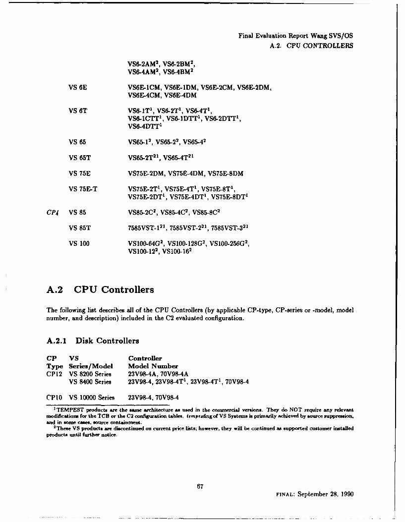
Final Evaluation Report Wang SVS/OSA.2. CPU CONTROLLERS
VSO-2AM 2, VS6-2BM2,VSO-4AM 2, VS6-4BM2
VS 6E VS6E-lCM, VS6E-1DM, VS6E-2CM, VS6E-2DM,VS6E-4CM, VS6E-4DM
VS 6T VS6-IT', VS6-2T 1, VSO-4T',VS6-lCTr 1 , VS6-IDTT', VS6-2DTT',VS-4DT
vs 65 VS65_1 2, VS65-2 2, VS65-4 2
VS 65T VS65-2T 21, VS65-4T 21
VS 75E VS75E-2DM, VS75E-4DM, VS75E-8DM
VS 75E-T VS75E-2T', VS75E-4T', V575E-8T',VS75E-2DT', VS75E-4DT1 , VS75E-8DT'
CP4 VS 85 VS85-2C 2, VS85-4C 2, VS85-8C 2
VS 85T 7585VST- 121, 7585V5T-22 ', 7585VST-3 21
vs 100 VSIOO-64G 2, VS100-128G 2, VSIOO-256G 2,
VSIOO-12 2, VSIOO-16 2
A.2 CPU Controllers
The following list describes all of the CPU Controllers (by applicable CP-type, CP-series or -model, modelnumber, and description) included in the C2 evaluated configuration.
A.2.1 Disk Controllers
CP VS Con trollerType Series/Model Model NuamberCP12 VS 8200 Series 23V98-4A, 70V98-4A
VS 8400 Series 23V98-4, 23V98-4T1 , 23V98-4T 1 , 70V98-4
('PlO VS 10000 Series 23V98-4, 70V98-4I EPESTpructs are the same architecture as used in the commercial versions. They do NOT require any relevant
modifications for the TCB or the C2 configuration tables. tempesting of VS Systems is primarily achieved by source suppression,and in some cases, source cont-ainment.
2 These VS products are discontinued on current price lists; however, they will be continued as supported customer installedproducts until further notice.
67FINAL: September 28, 1990

Final Evaluation Report Wang SVS/OSA.2. CPU CONTROLLERS
CP9 VS 5000 Series' 50V68, 50V68-Tl50V98, 50V98-Tl
CPS VS 300 Series 23V98-4, 70V98-4VS 7010 Series 23V98.4A, 70V98-4AVS 7100 Series 23V98-4, 23V98-4T1 , 7OV98-4VS 7300 Series 23V98-4, 23V98-4T', 70V98-4
CP7 VS 6/6E 25V50-2B, 25V50-4BVS 65/75E 25V50-2AVS 75E 25V50-4A, 25V98-4VS 6T/65T/75E-T 25V50-4AT1
VS fT/75E-T 25V98-4T'
CP4 All Models 22V28, 22V28A, 22V48VS 85-T 75V03T'
A.2.2 Magnetic Tape Controllers (MTCs)
This list only reflects available Magnetic Tape Controllers for selected CPUs that support parallel tape driveconfigurations.
CP VS ControllerType Series/Model Model NumberCP12 VS 8200 Series 23V95-IA, 23V95-2A
VS 8400 Series 23V95-1, 23V95-2, 23V95-2T1
OPlO VS 10000 Series 23V95-1, 23V95-2
CP9 VS 5000 Series" 50V68, 50V68-T'
CP8 VS 300 Series 23V95-1, 23V95-2VS 7010 Series 23V95-1A, 23V95-2AVS 7100 Series 23V95-1, 23V95-2, 23V95-2T1
VS 7300 Series 23V95-1, 23V95-2, 23V95-2T1
CP4 All Models 22V25, 22V15-2
3The VS MW0 Series also includes an embedded Resource Control Unit (RCU) that provides SCSI Controller support forup to seven SCSI compatible disk and tape devices. The RCU also provides support for the embedded 1.2 MB floppy diskettedrive.
4 Note: The VS 5000 Series also includes an embedded Resource Control Unit (RCU) that provides SCSI Controller supportfor up to seven SCSI compatible disk and tape devices.
68FINAL: September 28, 1990
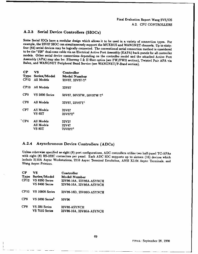
Final Evaluation Report Wang SVS/OS
A.2. CPU CONTROLLERS
A.2.3 Serial Device Controllers (SIOCs)
Some Serial IOCs have a modular design which allows it to be used in a variety of connection types. Forexample, the 23V67 SIOC can simultaneously support the MUXBUS and WANGNET channels. Up to sixty-four (64) serial devices may be logically connected. The conventional serial connection method is consideredto be the "928" dual-coax cable via an Electrical Active Port Assembly (EAPA) back-panels for all controllermodels. Other serial device connections depending on the controller model and the attached Active PortAssembly (APA) may also be: Fiberway I & II fiber optics (see FW/FWII section), Twisted Pair APA viaBalun, and WANGNET Peripheral Band Service (see WANGNET/P-Band section).
CP VS ControllerType Series/Model Model NumberCP12 All Models 23V67, 23V67-T1
CP10 All Models 23V67
CP9 VS 5000 Series 50V67, 50V97W, 50V97W-T 1
CP8 All Models 23V67, 23V67T 1
CP7 All Models 25V67VS 65T 25V67T1
'CP4 All Models 22V27All Models 22V47VS 85T 75V02T'
A.2.4 Asynchronous Device Controllers (ADCs)
Unless otherwise specified as eight (8) port configurations, ADC controllers utilize two half-panel TC-APAswith eight (8) RS-232C connectors per panel. Each ADC IOC supports up to sixteen (16) devices whichinclude 2110A Async Workstations, 2210 Async Terminal Emulation, ANSI X3.64 Async Terminals, andWang Async Printers.
CP VS ControllerType Series/Model Model NumberCP12 VS 8200 Series 23V86-16A, 23V86A-ASYNCH
VS 8400 Series 23V86-16A, 23V86A-ASYNCH
CPlO VS 10000 Series 23V86-16D, 23V86D-ASYNCH
CP9 VS 5000 Series5 50V96
CP8 VS 300 Series 23V86-ASYNCHVS 7010 Series 23V8-16A, 23V86A-ASYNCH
69FINAL: September 28, 1990
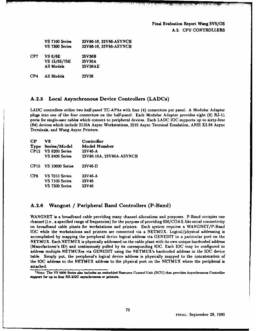
Final Evaluation Report Wang SVS/OS
A.2. CPU CONTROLLERS
VS 7100 Series 23V86-16, 23V86-ASYNCHVS 7300 Series 23V86-16, 23V86-ASYNCH
CP7 VS 6/6E 25V36BVS 15/65/75E 25V36AAll Models 25V36AE
CP4 All Models 22V36
A.2.5 Local Asynchronous Device Controllers (LADCs)
LADC controllers utilize two half-panel TC-APAs with four (4) connectors per panel. A Modular Adapterplugs into one of the four connectors on the half-panel. Each Modular Adapter provides eight (8) RJ-11ports for single-user cables which connect to peripheral devices. Each LADC IOC supports up to sixty-four(64) devices which include 2110A Async Workstations, 2210 Async Terminal Emulation, ANSI X3.64 AsyncTerminals, and Wang Async Printers.
CP VS ControllerType Series/Model Model NumberCP12 VS 8200 Series 23V46-A
VS 8400 Series 23V86-16A, 23V86A-ASYNCH
CP10 VS 10000 Series 23V46-D
CP8 VS 7010 Series 23V46-AVS 7100 Series 23V46VS 7300 Series 23V46
A.2.6 Wangnet / Peripheral Band Controllers (P-Band)
WANGNET is a broadband cable providing many channel allocations and purposes. P-Band occupies onechannel (i.e., a specified range of frequencies) for the purpose of providing 928/COAX-like serial connectivityon broadband cable plants for workstations and printers. Each system requires a WANGNET/P-BandIOC while the workstations and printers are connected via a NETMUX. Logical/physical addressing isaccomplished by mapping the peripheral device logical address via GENEDIT to a particular port on theNETMUX. Each NETMUX is physically addressed on the cable plant with its own unique hardcoded address(Manufacturer's ID) and continuously polled by its corresponding IOC. Each IOC may be configured toaddress multiple NETMUXes via GENEDIT using the NETMUX's hardcoded address in the IOC devicetable. Simply put, the peripheral's logical device address is physically mapped to the concatenation ofthe IOC address to the NETMUX address to the physical port on the NETMUX where the peripheral isattached.
SNote: The VS 50 Series also includes an embedded Resource Control Unit (RCU) that provides Asynchronous Controller
support for up to four RS-232C asynchronos or printers.
70FINAL: September 28, 1990
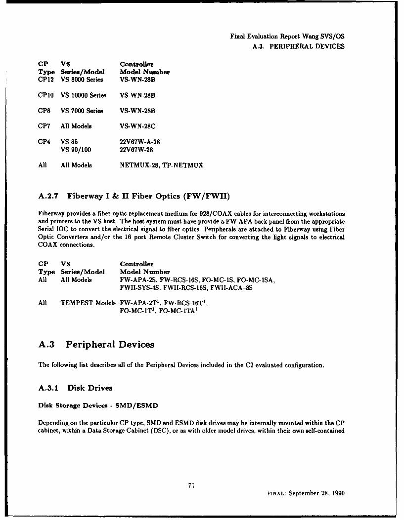
Final Evaluation Report Wang SVS/OS
A.3. PERIPHERAL DEVICES
CP VS ControllerType Series/Model Model NumberCP12 VS 8000 Series VS-WN-28B
CPlO VS 10000 Series VS-WN-28B
CP8 VS 7000 Series VS-WN-28B
CP7 All Models VS-WN-28C
CP4 VS 85 22V67W-A-28VS 90/100 22V67W-28
All All Models NETMUX-28, TP-NETMUX
A.2.7 Fiberway I & II Fiber Optics (FW/FWfl)
Fiberway provides a fiber optic replacement medium for 928/COAX cables for interconnecting workstationsand printers to the VS host. The host system must have provide a FW APA back panel from the appropriateSerial TOC to convert the electrical signal to fiber optics. Peripherals are attached to Fiberway using FiberOptic Converters and/or the 16 port Remote Cluster Switch for converting the light signals to electricalCOAX connections.
CP VS ControllerType Series/Model Model NumberAll All Models FW-APA-2S, FW-RCS-16S, FO-MC-1S, FO-MC-1SA,
FWII-SYS-4S, FWII-RCS-16S, FWII-ACA-8S
All TEMPEST Models FW-APA-2T 1 , FW-RCS-16T 1 ,FO-MC-ITI, FO-MC-1TA'
A.3 Peripheral Devices
The following list describes all of the Peripheral Devices included in the C2 evaluated configuration.
A.3.1 Disk Drives
Disk Storage Devices - SMD/ESMD
Depending on the particular CP type, SMD and ESMD disk drives may be internally mounted within the CPcabinet, within a Data Storage Cabinet (DSC), or as with older model drives, within their own self-contained
71FINAL: September 28, 1990

Final Evaluation Report Wang SVS/OSA.3. PERIPHERAL DEVICES
cabinet. For the purpose of listing the evaluation peripherals, only the Puzilual drive type model numbers arelisted.
CP VS PeripheralType Series/Model Model NumberCP12 VS 8000 Series 2265V-1, 2265V-2, 2265V-3, 2267V- 1,
2268V- 1, 22038V-2, 2268V-3, 2268V-4,2268 V-6D
VS 8000T Series 7565V-2T 1, 2267V-lT', 2268V-4T'
CPIO VS 10000 Series 2265V-1, 2265V-2, 2265V-3, 2267V-1,2268V-1, 2268V-2, 2268 V-3, 2268 V-4,2268V-6D
CP9 VS 5000 Series 2267V-1, 2268V-2, 2268V-3, 2268 V-4VS 5000T Series 2268 V-4T1
CP8 VS 7000 Series 2265V-1, 2265V-2, 2265V-3, 2267V-1,2268V-1, 2268V-2, 2268V-3, 2268V-4,2268 V-6D
VS 7000T Series 7565V-2T1, 2267V-1T', 2268 V-4T'
CP7 All Models 2265V-1, 2265V-2, 2265V-3,2280V-i, 2280V-2, 2280V-3
TEMPEST Models 7565V-2T1
CP4 All Models 2265V-1, 2265V-2, 2265V-3,2280V-1, 2280V-2, 2280V-3
VS 85T 7565V-2T'
Disk Storage Devices - SCSI
Depending on the particular CP type,, SCSI disk drives may be internally mounted within the CP cabinetand/or within a, SCSI Storage Module (SSM) or a, SCSI Mini Data Storage Cabinet (MDSC). For thepurpose of listing the evaluation peripherals, only the actual drive unit type model numbers are listed.
CP VS PeripheralType Series/Model Model NumberCP9 VS 5000 Series 2269V-3, 2269 V-4, 2269 V-5
VS 5000T Series 2269V-3T', 2269 V-4T1 , 2269V-5T'
CPT VS 6 2269VR-3B, 2269VR-4BVS 6E 2269V-3B, 2269V-413VS 6T 2269V-3T', 2269V-4T', 2269V-5T'VS 75E 2269 V-4A
72INAL: September 28, 1990
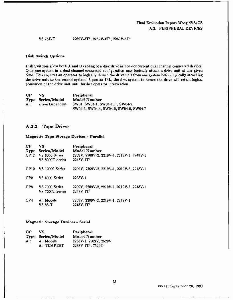
Final Evaluation Report Wang SVS/OS
A.3. PERIPHERAL DEVICES
VS 75E-T 2269V-3T 1 , 2269V-4T', 2269V-5T'
Disk Switch Options
Disk Switches allow both A and B cabling of a disk drive as non-concurrent dual channel connected devices.Only one system in a dual-channel connected configuration may logically attach a drive unit at any givenf*one. This requires an operator to logically detach the drive unit from one system before logically attachingthe drive unit to the second system. Upon an IPL, the first system to access the drive will retain logicalpossession of the drive unit until further operator intervention.
CP VS PeripheralType Series/Model Model NumberAll Drive Dependent SW04, SWO4-1, SW04-1T', SW04-2,
SW04-3, SW04-4, SW04-5, SW04-6, SW04-7
A.3.2 Tape Drives
Magnetic Tape Storage Devices - Parallel
CP VS PeripheralType Series/Model Model NumberCP12 V3, 8000 Series 2209V, 2209V-2, 2219V-l1, 2219V-3, 2248V-1I
VS 8000T Series 2248Nf-IT'
CP1O VS 10000 Serik!s 2209V, 2209V-2, 2219V- 1, 2219V-3, 2248V- I
CP9 VS 5000 Series 2238V- I
CP8 VS 7000 Series 2209V, 2209V-2, 2219V- 1, 2219V-3, 2248V- 1
VS 7000T Series 2248V-1T1
GP4 All Models 2209V, 2209V-2, 2219V-1, 2248V-1VS 85-T 2248V- iT1
Magnetic Storage Devices - Serial
CI' VS PeripheralType Series/Model Moide NumberAll All Models 2238V-1, 2,509V, 2529V
All TEMPEST 2238V-1IT', 7529TV
73FINAL: September 28, 1990
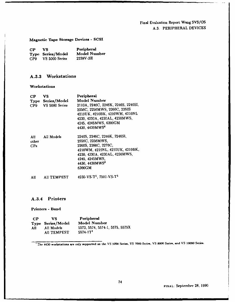
Final Evaluation Report Wang SVS/OSA.3. PERIPHERAL DEVICES
Magnetic Tape Storage Devices - SCSI
CP VS PeripheralType Series/Model Model NumberCP9 VS 5000 Series 2238V-3H
A.3.3 Workstations
Workstations
CP VS PeripheralType Series/Model Model NumberCP9 VS 5000 Series 2110A, 2246C, 2246K, 2246S, 224651,
2256C, 2256MWS, 22660, 2266S4210UK, 421013K, 4210WM, 4210NL4230, 4230A, 4230AL, 4230MWS,4245, 4245MWS, 6300GM4430, 4430MWS6
All All Models 2246S, 2246C, 2246K, 2246SI,other 2256C, 2256MWS,cps 2266S, 2266C, 2276C,
4210WM, 4210NL, 4210UK, 421013K,4230, 4230A, 4230AL, 4230MWS,4245, 4245MW5,4430, 4430MWS
6
6300GM
All All TEMPEST 4230-VS-TI, 7501-VS-TI
A.3.4 Printers
Printers - Band
CP VS PeripheralType Series/Model Model NumberAll All Models 5573, 5574, 5574-1, 5575, 5575X
All TEMPEST 5574-iT'
'The 4430 workstations are only supported on the VS 500 Series, VS 7000 Series, VS 8000 Series, and VS 10000 Series.
74FINAL: September 28, 1990
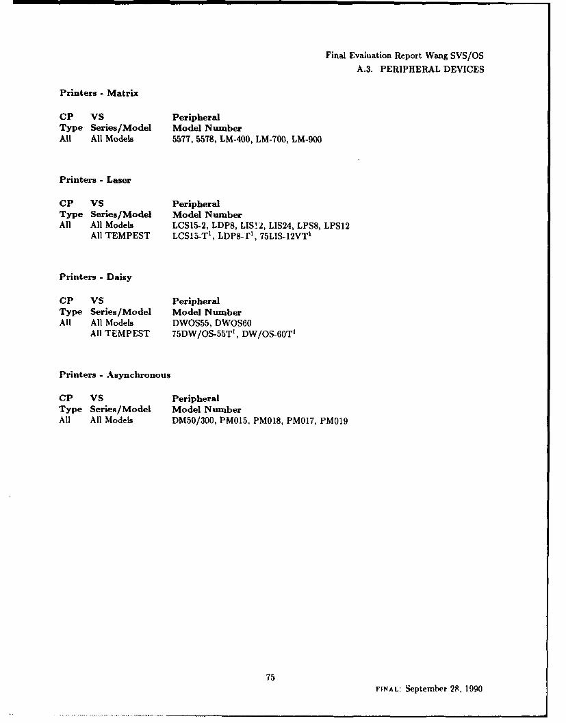
Final Evaluation Report Wang SVS/OSA.3. PERIPHERAL DEVICES
Printers - Matrix
CP VS PeripheralType Series/Model Model NumberAll All Models 5577, 5578, LM-400, LM-700, LM-900
Printers - Laser
CP VS PeripheralType Series/Model Model NumberAll All Models LCSl5-2, LDP8, LIS12, LIS24, LPS8, LPS12
All TEMPEST LCS15-T', LDP8-'f', 75L1S-12VTI
Printers - Daisy
CP VS PeripheralType Series/Model Model NumberAll All Models DWOS55, DWOS60
All TEM PEST 75DW/OS-55T', DW/OS-60T'
Printers - Asynchronous
CP VS PeripheralType Series/Model Model NunmberAll All Models DM50/300, PM0l5, PMO18, PMO17, PM019
75FINAL: September 28, 1990
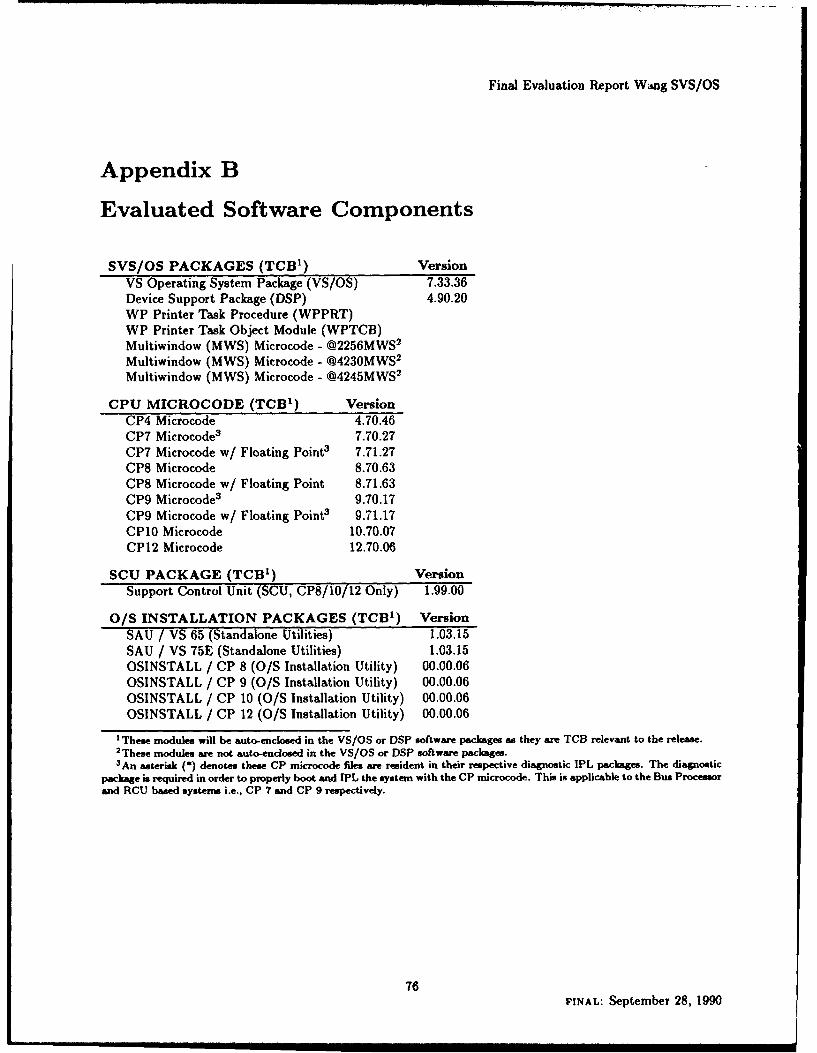
Final Evaluation Report Wang SVS/OS
Appendix B
Evaluated Software Components
SVS/OS PACKAGES (TCB 1) VersionVS Operating System Package (VS/OS) 7.33.36Device Support Package (DSP) 4.90.20WP Printer Task Procedure (WPPRT)WP Printer Task Object Module (WPTCB)Multiwindow (MWS) Microcode - @2256MWS2
Multiwindow (MWS) Microcode - @4230MWS2
Multiwindow (MWS) Microcode - @4245MWS2
CPU MICROCODE (TCB') VersionCP4 Microcode 4.70.46CP7 Microcode3 7.70.27CP7 Microcode w/ Floating Point 3 7.71.27CP8 Microcode 8.70.63CP8 Microcode w/ Floating Point 8.71.63CP9 Microcode 3 9.70.17CP9 Microcode w/ Floating Point3 9.71.17CP10 Microcode 10.70.07CP12 Microcode 12.70.06
SCU PACKAGE (TCB') VersionSupport Control Unit (SCU, CP8/10/12 Only) 1.99.00
O/S INSTALLATION PACKAGES (TCB') VersionSAU / VS 65 (Standalone Utilities) 1.03.15SAU / VS 75E (Standalone Utilities) 1.03.15OSINSTALL / CP 8 (O/S Installation Utility) 00.00.06OSINSTALL / CP 9 (O/S Installation Utility) 00.00.06OSINSTALL / CP 10 (O/S Installation Utility) 00.00.06OSINSTALL / CP 12 (O/S Installation Utility) 00.00.06
1 These modules will be auto-enclosed in the VS/OS or DSP software packages as they are TCB relevant to the release.2These modules are not auto-enclosed in the VS/OS or DSP software packages.3 An asterisk (*) denotes these CP microcode files are resident in their respective diagnostic IPL packages. The diagnostic
package is required in order to properly boot and IPL the system with the CP microcode. This is applicable to the Bus Processorand RCU based systems i.e., CP 7 and CP 9 respectively.
76FINAL: September 28, 1990
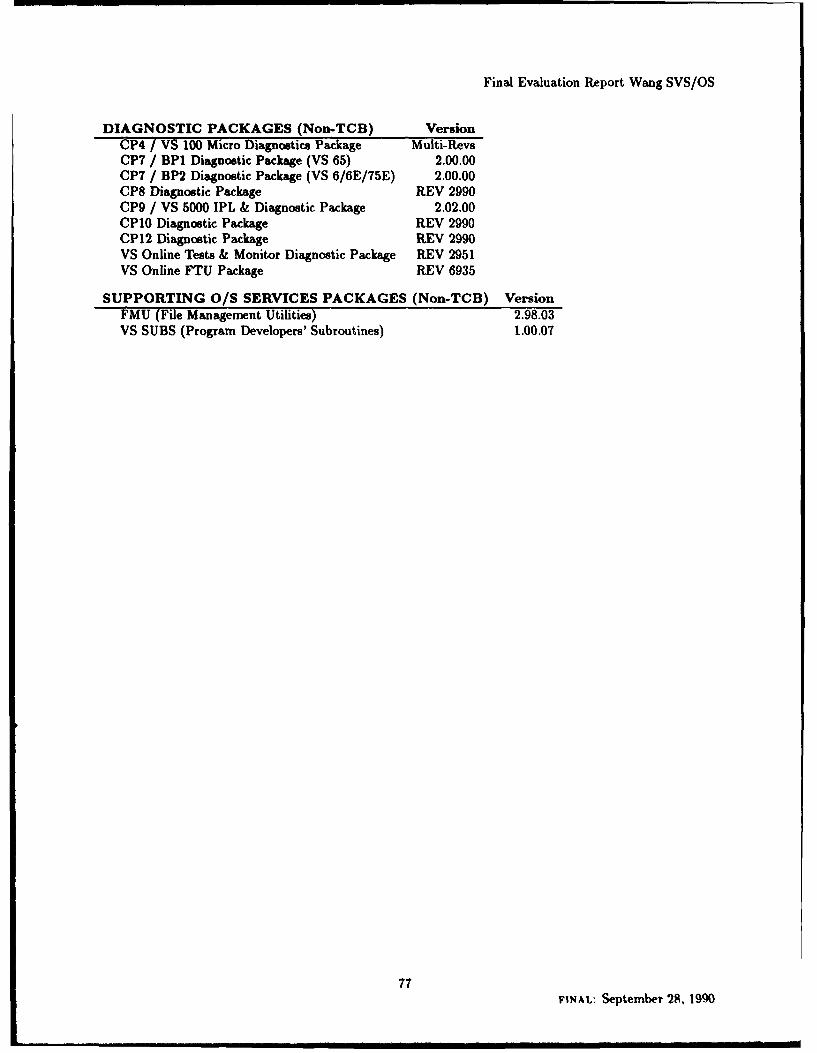
Final Evaluation Report Wang SVS/OS
DIAGNOSTIC PACKAGES (Non-TCB) VersionCP4 / VS 100 Micro Diagnostics Package Multi-RevsCP7 / BP1 Diagnostic Package (VS 65) 2.00.00CP7 / BP2 Diagnostic Package (VS 6/6E/75E) 2.00.00CP8 Diagnostic Package REV 2990CP9 / VS 5000 IPL & Diagnostic Package 2.02.00CP10 Diagnostic Package REV 2990CP12 Diagnostic Package REV 2990VS Online Tests & Monitor Diagnostic Package REV 2951VS Online FTU Package REV 6935
SUPPORTING O/S SERVICES PACKAGES (Non-TCB) VersionFMU (File Management Utilities) 2.98.03VS SUBS (Program Developers' Subroutines) 1.00.07
77FINAL: September 28, 190
Final Evaluation Report Wang SVS/OS
Appendix C
Glossary
Access Control List (ACL) A list of users and/or groups and their access (write, read, execute or null)used to control access to a file.
Access Mode One of four hierarchical representations (W - write; R - read; E - execute; blank - noaccess) used to specify the way a user can access protected files.
Alphanumeric A character set that contains letters, digits and other characters, such as punctuationmarks. Wang's standard set of such characters is A-Z, 0-9, and #, @, and $.
Arithmetic and Logic Unit (ALU) That portion of the CPU which performs matnematical calculationsand data comparisons.
Background Processing A workstation-independent, noninteractive processing environment that con-sists of one or more programs and procedures run by a controlling procedure.
Basic Assembly Language (BAL) The assembly language for Wang VS systems.
Bus Adapter (BA) An interface device that provides a mechanism for a CP to communicate with oneor more lOPs through the system's I/O bus.
Bus Interface Controller (BIC) An interface device which allows an 1/0 coprocessor to directly com-municate with the system bus.
Bus Processor (BP) A device which performs as an IOC that communicates with a device adaptor (DA).
Central Processor (CP) The central processing unit (CPU). That component of the computer composedof electrical circuitry which directs most of the computer's activities, and which consists of the control unit,the arithmetic/logic unit (ALU), and the processing registers.
Child Task A task that has been created by another task through the TINVOKE system service.
78FINAL: September 28, 1990

Final Evaluation Report Wang SVS/OS
CP Type A set of CPs that are based on the same hardware architecture (i.e., CP5, CP8, etc.).
Command Table Address (CTA) An address found within the I/O status table (lOST). A specificCTA entry points to the I/O command table (IOCT) for the IOC associated with a given I/O operation.
Control Mode A state of the computer system in which normal program execution is halted and specialfacilities for diagnostics, restart, initialization, and debugging are made available.
Data Management System (DMS) The operating system routines that control data file creation andaccess methods at the record, as opposed to file, level. DMS performs all input/output operations andcontrols the physical location of information on each volume.
Datagram A message sent from one task to another's mailbox. Any task can send a datagram to a mailboxfor which datagrams are allowed.
Dedicated System Task A privileged task not identified with a logged on user, but with the operatingsystem, instead.
Device Adapter (DA) An interface device that provides the functionality to talk with a given device.The DA, in conjunction with a bus processor (BP), handles all communication between the CP and devices.
Diagnostician A user that has been given the diagnostic privilege, which allows a task to load microcodeto an IOC, and gives it the ability to read and write IOC data structures. This privilege is designed to allowspecified users to run on-line diagnostics via system service routines.
Direct Memory Access (DMA) A method, used by controllers, to access main memory without CPUintervention.
Double-Word 64 bits.
Error Correction Circuitry (ECC) That feature of hardware which detects and corrects single biterrors and which detects and reports double bit errors but does not correct them.
Evaluated Products List (EPL) A list of evaluated products, the aim of which is to provide ADPsystem developers, managers, and users an authoritative evaluation of a system's relative suitability for usein processing sensitive information. The EPL is maintained by the NCSC.
Extent A group of physically contiguous records of a disk allocated for use by a single file.
79FINAL: September 28, 1990

Final Evaluation Report Wang SVS/OS
File A logical unit consisting of zero or more records of related information.
File Protection Class One of a set of classes used to control file access. A file protection class is designatedby a one-character file class protection code. There are 30 disjoint file classes which can be divided into twotypes, noted as Type I and Type II.
File protection class access rights A user's access to each of the 26 (A-Z) type II file protection classes.
Foreground Processing An interactive process associated with a workstation.
Group A list of user IDs which the SA defines and maintains, and which is used in access control lists.Each group is identified by a group ID.
Half-Word 16 bits.
Initial Program Load (IPL) The process of loading information into the system that it needs to startrunning.
Initiator task One of the tasks started by the System Operator as background tasks to which work canbe assigned by users with the SUBMIT service.
I/O Command Table (IOCT) A table of I/O command words (IOCWs) for the devices attached to anI/O processor. A command table address (CTA) specifies the address in main memory of each IOCT.
I/O Command Word (IOCW) A variable-length (I to 8 bytes) that specifies the next command to beexecuted for a device. Byte 0 holds the command code. Bytes 1-3 hold a data address or beginning addressof an indirect address list. Bytes 4-5 hold the data count (number of bytes to be operated on or transferred),and bytes 6 to the end may hold additional device-dependent information.
I/O Controller (IOC) An interface between the CP and an I/O device.
I/O Processor (lOP) The processor that controls the transfer of data between main storage and periph-eral units, relieving the CPU of this slower function.
I/O Status Table (lOST) A table which contains information about completed I/O operations. Thereis one 16-byte entry in the IOST for each supported controller on the system.
80FINAL: September 28, 1990
Final Evaluation Report Wang SVS/OS
I/O Status Word (IOSW) Eight bytes of data, stored at main memory location 0, that pass informationconcerning the status of an I/O device to the CPU. Byte 0 is the general status byte. Byte I is the errorstatus byte, stored if the error completion bit is set to 1 in the general status byte. Bytes 2-3 are the device-dependent bytes; bytes 4-5 hold the residual byte count. Bytes 2-6 (bits 16-55) are sometimes referred to asthe extended status bits for disk and tape.
Job A background task submitted for processing using the SUBMIT command or SVC.
Jump to Subroutine on Condition Indirect (JSCI) A machine instruction used to transfer programcontrol to a linked subroutine.
Kilobyte (KB) 1024 (210) bytes.
Library A collection of files, often of related contents, identified by a library name.
Link Level A level associated with a program. Each link level is represented by a data structure calledthe program file block, and a save area. Any files or program libraries introduced into the address space ina link level are deleted when the subtask completes and returns to its caller.
Local Page Table (LPT) In local memory a table consisting of one byte for each page in a segment.This byte contains the physical page number of that page when it is in main memory. There is one local pagetable for each region of virtual memory. These tables are used by the CPU in translating virtual memoryaddresses to main memory addresses.
Logon ID A unique character string (1 to 8 characters in length) which the SA assigns to a user. Thelogon ID is entered by the user at logon time.
Machine Language Architecture (MLA) The interface presented by the microcode on the various CPtypes. This architecture is the same across all CPs and defines such things as instructions, process levels,etc.
Mailbox A system memory data structure used in interprocess communication. It is used with datagramsand with sessions.
Megabyte (MB) 220 bytes.
Modifiable Data Area See "User Modifiable Data Area".
81FINAL: September 28, 1990

Final Evaluation Report Wang SVS/OS
Nucleus That part of the software, maintained in the file QSYS00On, (where n represents the CP type)that must be resident, or is called by a routine that is resident.
Operator A specific role assigned to a user by the SA. In this role a logged on user can perform specificsystem functions. The SA specifies this role by giving a user any or all of the operator functions (ResourceAccess Privileges) by using the VSSECUUE utility.
Parent Task A task that invokes another task by issuing the TINVOKE system call.
Personal Computer (PC) A microcomputer usually intended for the use of a single user.
Port A one-way communication path that is implemented in system-maintained data structures that sup-ports messages of up to 2046 bytes in length. Ports are named by the creator with a system unique 4-charactername.
Print Class A set of 26 classes (A-Z) to which print files are assigned. Each printer is assigned certainprint classes, so a file's print class determines which printers can print it. These are used for special formshandling and scheduling.
Procedure File A file containing system commands, user parameters, and statements unique to theprocedure language which is used to control the execution of a task.
Process See "task".
Process Level One of eight levels (0 - 7) assigned to the current execution state of the processor. Thislevel determines the degree of privilege assigned to the current task. Virtual memory accessible to a givenlevel is accessible to all higher process-level tasks, as well.
Program Control Word (PCW) An eight-byte code that contains program and system status informa-tion and which enables communication to take place between the program and the operating system.
Programmable Read-only Memory (PROM) Non-volatile memory which functions in a manner simi-lar to read-only memory (ROM), except the data or program instructions are not pre-recorded on the PROMchip when it is manufactured, thus allowing users this capability.
Page Frame 2048 contiguous bytes, starting on a 2048 byte boundary.
Page Table A section of main memory that defines the mapping of virtual address space to physicaladdress space.
82FINAL: September 28, 1990
Final Evaluation Report Wang SVS/OS
Random Access Memory (RAM) Volatile temporary storage for data and program instructions.
Record A collection of bytes up to 2048 bytes (2 KB) in length.
Reference and Change Table (RCT) A table which associates two bits - the reference and the changebit - with each page frame.
Region A part of the user's virtual memory space consisting of a varying number of contiguous pages.
Region Node A 16-byte entry in the Region Table that describes a particular region and points to thepage table for that region.
Region Node Table (RNT) A section of main memory that describes the user's virtual address space.It contains one region node entry for each region defined for the user.
Resource Control Unit (RCU) A special I/O coprocessor which, for CP9 systems, allows Workstation0 to interface with the system bus. The RCU orchestrates the IPL process.
Role One of five categories to which tasks are assigned. Four of these are for assignment to users.
Segment Control Register (SCR) A privileged 32-bit register holding the address of a task's mainmemory page table for a segment.
Semaphore A 2-word data structure that is used to synchronize processes.
Session A logical two-way communication between tasks that have agreed to communicate, with themailboxes on either end acting as gateways. Once agreement is reached, each task is free to send and receivemessages on the session. A mailbox is used at each end of the session as the repository for the messages.
Special Program Access Rights (SPAR) Rights comparable to file protection class access rights, butassociated with a program, not a user. They can only be specified by the SA. They specify that the programhas SA access rights (i.e., it executes with the role of the SA), or the access that the program has to eachof the 26 type II file protection classes. A dynamically linked program receives the task's access rights aswell as its own SPARs. In addition, a calling task can specify whether a linked program also receives anaccumulation of all the SPARs of the intermediately linked programs.
Stack Header Block (SHB) A data block describing the stack associated with one of a task's processlevels. Entries in an SHB hold the stack vector and the address of the most recently-built JSCI save area.SHBs are referred to by the operating system to control stack switching.
83FINAL: September 28, 1990
Final Evaluation Report Wang SVS/OS
Stack Header Block Table (SHBT) A table of eight addresses, each pointing to the stack header blockassociated with one of a task's process levels.
Supervisor Call (SVC) A machine instruction used by a task to invoke an operating system service.
Support Control Unit (SCU) A 16-bit microprocessor-based unit with a built-in 5.25 inch diskettedrive and a fixed-disk drive. The SCU consists of the system panel and the workstation that is cabled asdevice 0 on port 0, and, for CP8, CP10, and CP12 processors is the system console. The SCU runs a specialapplications software package known as SYSCON.
System Administrator (SA) The SA role is a specified account that is shipped with the system, witha predefined password. The SA can specify other users as an SA by using the VSSECURE utility to set anindicator in the user profile. An SA has autonomous control over the entire system.
System Bus Interface (SBI) An interface between the system bus and the I/O bus, thus allowing thesebuses to communicate.
System Console The system console consists of the system panel and that workstation attached as device0 on port 0, On VS7000 Series processors the System Console is the SCU.
System Services Those operating system functions called by user and system applications to perform filemanagement, I/O, memory management, and other services involving system resources. These services areavailable to programs through either the JSCI or SVC machine instructions.
Task An operating system schedulable entity to which system resources are allocated.
Translation Buffer (T-BUF) The local page table of the VS7310, VS)0000/100, and VS8400.
Translation RAM (T-RAM) A local page table (i.e., an area of local CP memory holding page framenumbers for the loaded portion of a task's virtual address space. This special hardware memory is separatefrom the main memory of the computer).
Trusted Computing Base (TCB) The totality of protection mechanisms within a computer system -including hardware, firmware, and software - the combination of which is responsible for enforcing a securitypolicy. A TCB consists of one or more components that together enforce a unified security policy overa product or system. The ability of a TCB to correctly enforce a security policy depends solely on themechanisms within the TCB and on the correct input by system administrative personnel of parameters(e.g., a user's clearance) related to the security policy.
84FINAL: September 28, 1990
Final Evaluation Report Wang SVS/OS
Unit Control Block Address (UCBA) The address of a unit control block (UCB) for a device. AUCBA is stored within an I/O command table.
Unprivileged User Any user that is not an operator, a diagnostician or a system administrator.
User ID A three-character unique code, assigned by the SA, which identifies the user to the system.
User Lock A data structure available to all user tasks to coordinate access to shared resources. Thismechanism is primarily available to coordinate access to shared files that have been mapped, by the KSKAPsystem service, to an area of the task's virtual address space.
User Modifiable Data Area A portion of a task's virtual memory used by a task running at processlevel 0 to store program variables and buffers, as well as the stack. The size of the user modifiable data areais fixed for each user by the SA.
Virtual Address A 24-bit address consisting of a 13-bit virtual page index and an 11-bit byte offset.
Volume A portion of a single unit of storage that is accessible to a single read/write mechanism. A diskpack and a floppy disk are examples of volumes.
Volume Protection Label (VPL) An adhesive paper label that the operator must physically attach toeach tape volume.
Volume Set A group of one or more volumes used to store very large files or very many related files.
Wait level User tasks are assigned to one of two wait levels. Wait level 1 is the user wait level, andwait level 2 is the command processor/operator interface wait level. The system maintains separate areas incontrol blocks for a task's context (including screen contents) for each of these two wait levels.
Word 32 bits.
85FINAL: September 28, 1990

Final Evaluation Report Wang SVS/OS
BIBLIOGRAPHY
Bibliography
[1] SVS/OS with Controlled Access Protection (CAP) RM-Plan, Wang Laboratories, Inc., 1990.
[2] Rating Maintenance Phase Program Document, National Computer Security Center, 23 June 1989,NCSC-TG-013. June 1989.
[31 VS Trusted Facility Manual (TFM) Documentation Guide, Wang Laboratories, Inc., 1990, 715-3692.
[4] VS5000 Series Processor Handbook, Wang Laboratories, Inc., October 1988.
VS7000-T Series Processor Handbook, Wang Laboratories, Inc., May 1988.
VS7100 Series Processor Handbook, Wang Laboratories, Inc., July 1987.
VS7310 Processor Handbook, Wang Laboratories, Inc., August 1987.
VS8200 Family Processor Handbook, Wang Laboratories, Inc., September 1989.
VSIO000 Series Processor Handbook, Wang Laboratories, Inc., February 1989.
[5] Secure VS Operating System with Controlled Access Protection Guide, Wang Laboratories, Inc., 1990,715-2749.
[6] Secure VS Operating System with Controlled Access Protection (SVS/OS with CAP) Release 1 SoftwareBulletin Wang Laboratories, Inc., June 1990.
[7] Secure VS Operating System with Controlled Access Protection (SVS/OS with CAP) Release I CustomerSoftware Release Notice (draft), Wang Laboratories, Inc., September 1989.
[8] VS GENEDIT Utility Reference, Release 7 Series, Wang Laboratories, Inc., December 1989.
[9] VS BACKUP and VOLCOPY User's Guide, Wang Laboratories, Inc., 1990, 715-2383.
[10] Department of Defense Trusted Computer System Evaluation Criteria, December 1985, DOD 5200.28-STD.
[111 VS Data Management System Reference, 1st Edition, Wang Laboratories, Inc., 1984, 800-1124-01.
[12] VS DMS/TX Reference, 1st Edition, Wang Laboratories, Inc., 1983, 800-1128-01.
[131 VS Extended Data Management System (XDMS) Reference, 1st Edition, Wang Laboratories, Inc., 1988,715-1159.
[14] VS Operating System and System Utilities Documentation Guide, Release 7 Series, Wang Laboratories,Inc., 1988, 715-0296A.
[151 VS Procedure Language Reference, 6th Edition, Wang Laboratories, Inc., 1987, 800-1205-06.
[16] VS Assembly Language Reference, 3rd Edition, Wang Laboratories, Inc., 1982, 800-1200AS-03.
[17] VS Operating System and System Utilities Error Message Reference, 1st Edition, Wang Laboratories,Inc., 1988, 715-0621.
86FINAL: September 28, 1990

Final Evaluation Report Wang SVS/OS
BIBLIOGRAPHY
[18] VS Syslem Security Test Reference, C2 Certification T.l Documentation, Volume 1-9, Version 1.00.00,Wang Laboratories, Inc., 1988, 714-0193 (proprietary).
(19] VS File Management and Application Development Utilities Reference, 1st Edition, Wang Laboratories,Inc., 1988, 715-1715.
[20] VS System Media, Transfer, and Device Utilities Rtference, 1st Edition, Wang Laboratories. Inc., 1988,715-1716.
[211 VS ', I em Administration and Analysis Utilities Reference, 1st Edition, Wang Laboratories, Inc., 1988,715-1717.
[22] VS System User's Introduction, Release 7 Series, Fourth Edition, Wang Laboratories, Inc., 188, 715-0417C.
[23] VS Editor Reference, Release 7 Series, 1st Edition, Wang Laboratories, Inc., 1988, 715-1143.
[24] VS Linker Reference, Release 7 Series, 1st Edition, Wang Laboratories, Inc., 1987, 715-1145.
[25] VS Symbolic Debugger Reference, Release 7 Series, 1st Edition, Wang Laboratories, Inc., 1987, 715-1144.
[26] VS VSSUBS Reference, 1st Edition, Wang Laboratories, Inc., 1988, 715-0599.
[27] VS Principles of Operation, Volumes I and II, Wang Laboratories, Inc., 1990. Volume 1 (715-4098) isthe customer version. Volume 2 (INT-0495) is proprietary.
[28] VS System TCB CPU Architecture Analysis, VS/OS 7.30 TCB/C2, Version 1.0, Wang Laboratories,Inc., April 1988, (proprietary).
(29J Potential CPU/Peripheral List for TCB/Cf.
[30] VS System Informal Security Policy Statement, Version 2.1, Wang Laboratories, Inc., 1988, INT-0496(proprietary).
[31] VS System Informal Security Policy Statement: Wang Response to NCSC Questions, VS/OS 7.30TCB/C2, Wang Laboratories, Inc., March 1988 (proprietary).
[32] VS/OS TCB Definition and Mapping Document, Wang Laboratories, Inc., March 1988 (proprietary).
[33] VS Security Features User's Guide, NCSC Draft, Wang Laboratories, Inc., 1988, 715-0793.
[34] VS Operating System Services Reference, Volumes 1 and 2, Wang Laboratories, Inc., 1990, 715-2344,715-2345.
[35] Trusted Computing System Installation and Administration Guide, NCSC Draft, Wang Laboratories,Inc., April 1988.
[36] VS Enhanced System Access Controls (ESAC) Guide, NCSC Draft, Wang Laboratories, Inc., 1990,715-4037.
[371 VS GENEDIT Utility Reference, Release 7 Series, 1st Edition, Wang Laboratories, Inc., 1988, 715-1511.
[38] VS System Operator's Guide, Wang Laboratories, Inc., 1990, 7 5?J5G.
[39] VS Operating System Internals Manual, 1st Edition, Wang Laboratories, Inc., 1990, INT-0492 (propri-etary).
87FINAL: September 28, 1990

Final Evaluation Report Wang SVS/OS
BIBLIOGRAPHY
[40] VS Utilities Internals Manual, 1st Edition, Wang Laboratories, Inc., 1990, INT-0494 (proprietary).715-1839.
[41] VS System Development Tools , Version 5, Wang Laboratories, Inc., 1990, INT-0493 (proprietary).714-0195.
[42] WP Queue Entries in the OS/VS Queue, Project Proposal, Version 1.2, 28 September 1987 (proprietary).
[43] SUBMITting WP Print Requests, Functional Specification, Version 1.1, 23 October 1987 (proprietary).
[44] SUBMITting WP Print Requests, Design Specification, Version 1.5 , 31 March 1988 (proprietary).
[45] Integrated WP/DP Printing- WP Component, Functional Specification, 28 July 1987 (proprietary).
[46] Group Editor Using PACE, Functional Specification, Version 3.4, 20 January 1988 (proprietary).
[47] Group Editor Using PACE, Design Specification, Version 1.3, 16 February 1988 (proprietary).
[48] Prevent GROUPLST RE-USE, Functional Specification, Version 2.1, January 15, 1988 (proprietary).
[49] Fault Tolerant Event Logging, Functional/Design Specification, Version 3.0, 29 February 1988 (propri-etary).
[50] C2 Disk Mount Procedures, 30 March 1988 (proprietary).
[51] IPC/XMIT Message Auditing Facility, Functional Specification, Version 1.2, November 17, 1987 (pro-prietary).
[52] IPC/XMIT Message Auditing Facility, Design Specification, Version 1.2, November 17, 1987 (propri-etary).
[53] VS Operating System, Release 7.18, Customer Software Release Notice, 1st Edition, Wang Laboratories,Inc., 1988, 715-2208.
[54] VS Device Support, Release 2.99, Customer Software Release Notice, 1st Edition, Wang Laboratories,Inc., 1988, 715-2235.
[55] VS 5000 Series Diagnostics, Release 1, Customer Software Release Notice, 1st Edition, Wang Labora-tories, Inc., 1988, 715-2162.
[56] VS VSSUBS, Release 1.00.00, Customer Software Release Notice, 1st Edition, Wang Laboratories, Inc.,1988, 715-2233.
[57] VS File Management and Application Development Utilities, Release 00.00.07, Customer Software Re-lease Notice, 1st Edition, Wang Laboratories, Inc., 1988, 715-2234.
[58] VS Standalone Utilities (SA U), Release 1.03.13, Customer Software Release Notice, 1st Edition, WangLaboratories, Inc., 1988, 715-2232.
[59] VS Support Control Unit (SCU), Release 1.05, Customer Software Release Notice, 1st Edition, WangLaboratories, Inc., 1987, 715-1508.
[60] VS7100 Series Processor Handbook, Wang Laboratories, Inc., July 1987.
[61] Subsets of Standard Code for Information Interchange, Federal Information Processing Standards Pub-lication 15, U.S. Department of Commerce, National Bureau of Standards, 1 October, 1971.
88FINAL: September 28, 1990

UNCLASSIFIEDSECURITY CLASSIFICATION OF THIS PAGE
REPORT DOCUMENTATION PAGEla. REPORT SECURITY CLASSIFICATION 1 b. RESTRICTIVE MARKINGS
UNCLASSIFIED
2a. SECURITY CLASSIFICATION AUTHORITY 3. DISTRIBUTION/AVAILABILITY OF REPORTUNLIMITED DISTRIBUTION
2b. DECLASSIFICATION/DOWNGRADING SCHEDULE
4. PERFORMING ORGANIZATION REPORT NUMBER(S) 5. MONITORING ORGANIZATION REPORT NUMBER(S)CSC-EPL-90/004 S236,000
6a. NAME OF PERFORMING ORGANIZATION 6b OFFICE SYMBOL 7a. NAME OF MONITORING ORGANIZATIONNational Computer Security Center (Ifapphcable) C71
6c. ADDRESS (City, State and ZIP Code) 7b. ADDRESS (City, State and ZIP Code)
9800 Savage RoadFt. George G. Meade, MD 20755-6000
8a. NAME OF FUNDING/SPONSORING 8b. OFFICE SYMBOL 9. PROCUREMENT INSTRUMENT IDENTIFICATION NUMBERORGANIZATION (If a~picable)
8c, ADDRESS (CigyState and ZIP Code) 10. SOURCE OF FUNDING NOS.
PROGRAM PROJECT TASK WORK UNITELEMENT NO. NO. NO. NO.
11. TITLE (Include Security Classification)Final Evaluation Report Wang Lab Inc., SVS/OS CAP 1.0
12. PERSONAL AUTHOR(S)Timothy J. Bergendahl, Duane A. Souder, Anthony J. Apted, James L. Arnold Jr. Ronald J Bottomly, R. Kris Britton
1 3a. TYPE OF REPORT 1 3b. TIME COVERED 14. DAT(ff 6VgQ1P(rM/a) 1 AECU.Final FROM __TO_ Jr
16. SUPPLEMENTARY NOTATION
17 COSATI CODES 18. SUBJECT TERMS (Continue on reverse if necessary and identify by block number)
FIELD GROUP SUB. GR. NSA, Wang Laboratories Incorporated, TCSEC, C2, SVS/OS CapFIEL GROP SU GR 1.0
19. ABSTRACT (Continue on reverse side if necessary and identify by block number)The National Security Agency's (NSA) Trusted Product and Network Security Evaluations Divisionexamined the security protection mechanisms provided by Wang Laboratories, Incorporated's SVS/OSCAP 1.0. It was evaluated against the DoD Trusted Computer System Evaluation Criteria (TCSEC) andthe evaluation team determined that the system meets all criteria for the C2 level of trust.
This report documents the findings of the evaluation
20. DISTRIBUTION/AVAILABILITY OF ABSTRACT 21. ABSTRACT SECURITY CLASSIFICATION
UNCLASSIFIED/UNLIMITED UNCLASSIFIED
22a. NAME OF RESPONSIBLE INDIVIDUAL 22b. TELEPHONE NUMBER 8b. OFFICE SYMBOLPATRICIA L. MORENO (Icude Am& Code) (301)859-4458 C71
DD FORM 1473,83 APR EDITION OF 1 JAN 73 IS OBSOLETE. UNCLASSIFIEDSECURITY CLASSIFICATION OF THIS PAGE