wand-einbaugerät wallinstalledunit groupedouble-fluxmural … · 2015-02-07 · kwl ec 60 eco l1 n...
TRANSCRIPT

Helios Ventilatoren
MONTAGE- UND BETRIEBSVORSCHRIFT NR. 86667
INSTALLATION AND OPERATING INSTRUCTIONS NO. 86667
NOTICE DE MONTAGE ET D’UTILISATION N° 86667
Wand-EinbaugerätWall installed unitGroupe double-flux mural
EcoVentKWL EC 60 Eco
-Wärmerückgewinnung und EC-Technikfür Einzelräume.-Heat recovery and EC-motor technologyfor single rooms- Ventilation décentralisée avec récupérationde chaleur et moteurs EC.
D
UK
F

Helios VentilatorenMONTAGE- UND BETRIEBSVORSCHRIFT NR. 86667
Inhaltsverzeichnis
KAPITEL 1. ALLGEMEINE MONTAGE- UND BETRIEBSHINWEISE . . . . . . . . . . . . . . . . . . . . . . . . . . . . . . . . . . .Seite 11.0 Wichtige Informationen . . . . . . . . . . . . . . . . . . . . . . . . . . . . . . . . . . . . . . . . . . . . . . . . . . . . . . . . . . . . . . . . .Seite 11.1 Warn- und Sicherheitshinweise . . . . . . . . . . . . . . . . . . . . . . . . . . . . . . . . . . . . . . . . . . . . . . . . . . . . . . . . . . .Seite 11.2 Garantieansprüche – Haftungsausschluss . . . . . . . . . . . . . . . . . . . . . . . . . . . . . . . . . . . . . . . . . . . . . . . . . . .Seite 11.3 Vorschriften – Richtlinien . . . . . . . . . . . . . . . . . . . . . . . . . . . . . . . . . . . . . . . . . . . . . . . . . . . . . . . . . . . . . . . .Seite 11.4 Sendungsannahme . . . . . . . . . . . . . . . . . . . . . . . . . . . . . . . . . . . . . . . . . . . . . . . . . . . . . . . . . . . . . . . . . . . .Seite 11.5 Einlagerung . . . . . . . . . . . . . . . . . . . . . . . . . . . . . . . . . . . . . . . . . . . . . . . . . . . . . . . . . . . . . . . . . . . . . . . . . .Seite 11.6 Einsatzbereich – Anwendung . . . . . . . . . . . . . . . . . . . . . . . . . . . . . . . . . . . . . . . . . . . . . . . . . . . . . . . . . . . . .Seite 11.7 Wirkungsweise . . . . . . . . . . . . . . . . . . . . . . . . . . . . . . . . . . . . . . . . . . . . . . . . . . . . . . . . . . . . . . . . . . . . . . .Seite 11.8 Leistungsdaten . . . . . . . . . . . . . . . . . . . . . . . . . . . . . . . . . . . . . . . . . . . . . . . . . . . . . . . . . . . . . . . . . . . . . . .Seite 11.9 Feuerstätten . . . . . . . . . . . . . . . . . . . . . . . . . . . . . . . . . . . . . . . . . . . . . . . . . . . . . . . . . . . . . . . . . . . . . . . . .Seite 11.10 Elektrischer Anschluss . . . . . . . . . . . . . . . . . . . . . . . . . . . . . . . . . . . . . . . . . . . . . . . . . . . . . . . . . . . . . . . . . .Seite 21.11 Technische Daten . . . . . . . . . . . . . . . . . . . . . . . . . . . . . . . . . . . . . . . . . . . . . . . . . . . . . . . . . . . . . . . . . . . . .Seite 21.12 Zubehör . . . . . . . . . . . . . . . . . . . . . . . . . . . . . . . . . . . . . . . . . . . . . . . . . . . . . . . . . . . . . . . . . . . . . . . . . . . . .Seite 2
KAPITEL 2. LIEFERWEISE / BESTELLUMFANG . . . . . . . . . . . . . . . . . . . . . . . . . . . . . . . . . . . . . . . . . . . . . . . . . .Seite 22.0 Lieferweise / Bestellumfang . . . . . . . . . . . . . . . . . . . . . . . . . . . . . . . . . . . . . . . . . . . . . . . . . . . . . . . . . . . . . .Seite 2
KAPITEL 3. MONTAGE/AUFSTELLUNG . . . . . . . . . . . . . . . . . . . . . . . . . . . . . . . . . . . . . . . . . . . . . . . . . . . . . . . .Seite 33.0 Wandmontage KWL 60 RS Rohbauset . . . . . . . . . . . . . . . . . . . . . . . . . . . . . . . . . . . . . . . . . . . . . . . . . . . . .Seite 33.1 Steuer- und Netzzuleitung verlegen . . . . . . . . . . . . . . . . . . . . . . . . . . . . . . . . . . . . . . . . . . . . . . . . . . . . . . . .Seite 33.2 Montage KWL EC 60 Eco Lüftungseinsatz . . . . . . . . . . . . . . . . . . . . . . . . . . . . . . . . . . . . . . . . . . . . . . . . . .Seite 33.3 Montage KWL 60 WV Wandhülsenverlängerung . . . . . . . . . . . . . . . . . . . . . . . . . . . . . . . . . . . . . . . . . . . . . .Seite 33.4 Montage KWL 60 DR Distanzrahmen . . . . . . . . . . . . . . . . . . . . . . . . . . . . . . . . . . . . . . . . . . . . . . . . . . . . . .Seite 4
KAPITEL 4. ELEKTROANSCHLUSS . . . . . . . . . . . . . . . . . . . . . . . . . . . . . . . . . . . . . . . . . . . . . . . . . . . . . . . . . . . .Seite 44.0 Elektrischer Anschluss . . . . . . . . . . . . . . . . . . . . . . . . . . . . . . . . . . . . . . . . . . . . . . . . . . . . . . . . . . . . . . . . . .Seite 44.1 Schaltplan SS-949 für KWL EC 60 Eco . . . . . . . . . . . . . . . . . . . . . . . . . . . . . . . . . . . . . . . . . . . . . . . . . . . . .Seite 44.2 Bedienelement KWL 60 BU . . . . . . . . . . . . . . . . . . . . . . . . . . . . . . . . . . . . . . . . . . . . . . . . . . . . . . . . . . . . . .Seite 4
KAPITEL 5. REINIGUNG UND WARTUNG . . . . . . . . . . . . . . . . . . . . . . . . . . . . . . . . . . . . . . . . . . . . . . . . . . . . . . .Seite 55.0 Kondensatableitung . . . . . . . . . . . . . . . . . . . . . . . . . . . . . . . . . . . . . . . . . . . . . . . . . . . . . . . . . . . . . . . . . . . .Seite 55.1 Service . . . . . . . . . . . . . . . . . . . . . . . . . . . . . . . . . . . . . . . . . . . . . . . . . . . . . . . . . . . . . . . . . . . . . . . . . . . . .Seite 55.2 Reinigung – Wartung . . . . . . . . . . . . . . . . . . . . . . . . . . . . . . . . . . . . . . . . . . . . . . . . . . . . . . . . . . . . . . . . . . .Seite 5
Korrekte Entsorgung dieses Produktes (Elektromüll)Die Kennzeichnung auf dem Produkt bzw. auf der dazugehörigen Montage- und Betriebsvorschrift gibt an, dass es nach seiner Lebensdauer nicht zusammen mitdem normalen Haushaltsmüll entsorgt werden darf. Entsorgen Sie dieses Gerät bitte getrennt von anderen Abfällen, um der Umwelt bzw. der menschlichen Gesund-heit nicht durch unkontrollierte Müllbeseitigung zu schaden. Recyceln Sie das Gerät, um die nachhaltige Wiederverwertung von stofflichen Ressourcen zu fördern.Private Nutzer sollten den Händler, bei dem das Produkt gekauft wurde, oder die zuständigen Behörden kontaktieren, um in Erfahrung zu bringen, wie sie das Gerätauf umweltfreundliche Weise recyceln können.Gewerbliche Nutzer sollten sich an Ihren Lieferanten wenden und die Bedingungen des Verkaufsvertrags konsultieren. Dieses Produkt darf nicht zusammen mit ande-rem Gewerbemüll entsorgt werden.
DEUTSCH

1.0 Wichtige InformationenZur Sicherstellung einer einwandfreien Funktion und zur eigenen Sicherheit sind alle nachstehenden Vorschriften genaudurchzulesen und zu beachten. Der Elektroanschluss muss bis zur Endmontage allpolig vom Netz getrennt werden!Die Montage- und Betriebsvorschrift als Referenz am Gerät aufbewahren. Nach der Endmontage muss dem Betreiber(Mieter/Eigentümer) das Dokument ausgehändigt werden.
1.1 Warn- und SicherheitshinweiseNebenstehendes Symbol ist ein sicherheitstechnischer Warnhinweis. Alle Sicherheitsvorschriften bzw. Symbolemüssen unbedingt beachtet werden, damit jegliche Gefahrensituation vermieden wird.
1.2 Garantieansprüche – HaftungsausschlussWenn die nachfolgenden Ausführungen nicht beachtet werden, entfällt unsere Gewährleistung. Gleiches gilt für Haf-tungsansprüche an den Hersteller.Der Gebrauch von Zubehörteilen, die nicht von Helios empfohlen oder angeboten werden, ist nicht statthaft. Eventuellauftretende Schäden unterliegen nicht der Gewährleistung.
1.3 Vorschriften – RichtlinienBei ordnungsgemäßer Installation und bestimmungsgemäßem Betrieb entspricht das Gerät den zum Zeitpunkt seinerHerstellung gültigen Vorschriften und CE-Richtlinien.
1.4 SendungsannahmeDie Sendung ist sofort bei Anlieferung auf Beschädigungen und Typenrichtigkeit prüfen. Falls Schäden vorliegen umge-hend Schadensmeldung unter Hinzuziehung des Transportunternehmens veranlassen. Bei nicht fristgerechter Rekla-mation gehen evtl. Ansprüche verloren.
1.5 EinlagerungBei Einlagerung über einen längeren Zeitraum sind zur Verhinderung schädlicher Einwirkungen folgende Maßnahmenzu treffen:Schutz durch trockene, luft- und staubdichte Verpackung (Kunststoffbeutel mit Trockenmittel und Feuchtigkeitsindika-toren). Der Lagerort muss erschütterungsfrei, wassergeschützt und frei von übermäßigen Temperaturschwankungensein. Schäden, deren Ursprung in unsachgemäßem Transport, unsachgemäßer Einlagerung oder Inbetriebnahme lie-gen, sind nachweisbar und unterliegen nicht der Gewährleistung.
1.6 Einsatzbereich – AnwendungDie Wärmerückgewinnungsgeräte KWL EC 60 Eco sind für den Einbau in Außenwände zur Be- und Entlüftung vonkleinen und großen Einzelräumen vorgesehen. Für eine mittelgroße Wohneinheit wird die Installation von zwei Gerätenempfohlen.Die serienmäßige Ausstattung erlaubt die Aufstellung und den Einsatz in frostfreien Räumen >+ 5 °C.Bei Betrieb unter erschwerten Bedingungen, wie z.B. hohe Feuchtigkeit, längere Stillstandzeiten, starke Verschmut-zung, übermäßige Beanspruchung durch klimatische sowie technische, elektronische Einflüsse, ist eine Rückfrage undEinsatzfreigabe erforderlich, da die Serienausführung hierfür u. U. nicht geeignet ist.Ein bestimmungsfremder Einsatz ist nicht zulässig!
1.7 WirkungsweiseIm Kreuzstromwärmetauscher „kreuzen“ sich der kalte Außenluftstrom und der warme Abluftstrom ohne direkt mitein-ander in Kontakt zu kommen. Durch dieses Verfahren werden über 70 % der Wärme der Abluft auf die Zuluft übertragen.
1.8 LeistungsdatenZum Erreichen der vorgesehenen Leistung ist ein ordnungsgemäßer Einbau, sowie eine freie An- bzw. Absaugungsicher zu stellen.
1.9 FeuerstättenDie gleichzeitige Verwendung von kontrollierter Wohnungslüftung und raumluftabhängigen Feuerstätten (Kachelofen,Gastherme etc.), bedingt die Beachtung aller geltenden Vorschriften. In nach dem Stand der Technik dichten Wohnun-gen ist ein Betrieb einer raumluftabhängigen Feuerstätte nur mit separater Brennluftzuführung erlaubt; nur dann sindKWL und Feuerstätte entkoppelt voneinander bedarfsgerecht betreibbar.Die einschlägig geltenden Vorschriften für den gemeinsamen Betrieb von Feuerstätte, Wohnungslüftung, Dunstabzugs-haube (Bundesverband des Schornsteinfegerhandwerks-Zentralinnungsverband (ZIV)) sind zu beachten!
Allgemeine baurechtliche AnforderungenDie Lüftungsgeräte mit Wärmerückgewinnung KWL EC 60 Eco dürfen nur dann in Räumen mit anderen raumluftab-hängigen Feuerstätten installiert und betrieben werden, wenn deren Abgasabführung durch besondere Sicherheitsein-richtungen überwacht wird, die im Auslösefall auch die Lüftungsanlage abschalten (z.B. Temperaturthermostat mitelektrischer Aufschaltung auf das Lüftungsgerät mit Wärmerückgewinnung); damit wird das KWL während der „Brenn-dauer“ ausgeschaltet. Dabei muss sichergestellt werden, dass durch den Betrieb der Wohnungslüftungsanlage keingrößerer Unterdruck als 4 Pa in der Wohneinheit erzeugt wird.Das Lüftungsgerät mit Wärmerückgewinnung KWL EC 60 Eco darf nicht gleichzeitig mit Festbrennstoff-Feuerstättenund nicht in Wohneinheiten mit raumluftabhängigen Feuerstätten, die an mehrfach belegte Abgasanlagen angeschlos-sen sind, betrieben werden. Für den bestimmungsgemäßen Betrieb der mit einem Lüftungsgerät mit Wärmerückge-winnung KWLC EC 60 Eco errichteten Lüftungsanlage müssen eventuell vorhandene Verbrennungsluftleitungen sowieAbgasanlagen von Festbrennstoff-Feuerstätten absperrbar sein.
1
Wand-Einbaugerät EcoVent KWL EC 60 EcoMontage- und Betriebsvorschrift
KAPITEL 1
ALLGEMEINE MONTAGE-UND BETRIEBSHINWEISE
�
HINWEIS �
D

1.10 Elektrischer AnschlussVor allen Wartungs- und Installationsarbeiten oder vor Öffnen des Schaltraumes ist das Gerät allpolig vomNetz zu trennen! Der elektrische Anschluss darf nur von einer autorisierten Elektrofachkraft entsprechend dennachstehenden Anschlussplänen ausgeführt werden. Der Elektroanschluss muss bis zur Endmontage allpoligvom Netz getrennt werden! Die einschlägigen Normen, Sicherheitsbestimmungen (z.B. DIN VDE 0100) sowie die TABder EVUs sind unbedingt zu beachten. Ein allpoliger Netztrennschalter / Revisionsschalter, mit mindestens 3 mm Kon-taktöffnung (VDE 0700 T1 7.12.2 / EN 60335-1) ist zwingend vorgeschrieben. Das integrierte dreistufige Bedienele-ment KWL 60 BU ist mittels Steuerleitung mit dem Lüftungseinsatz des Gerätes verbunden. Die Netzleitung (flexibleLeitung) wird an der Steckerbuchse angeschlossen (siehe Seite 4, Schaltplan SS-949).
1.11 Technische DatenSpannung/Frequenz 230 V~/50 Hz Anschluss nach Schaltplan SS-949Nennstrom A 0,05 Temperatur Arbeitsbereich -20 °C bis 40 °CSchutzart IP X4 Gewicht Rohbauset 3,25 kgElektrische Zuleitung bis UV NYM-J 3 x 1,5 mm2 Gewicht Lüftungseinsatz 5,55 kgNetz-Zuleitung über flexible Leitung 2 x 1,5 mm2 Förderleistungen Vm3/h 60 / 30 / 17
1.12 ZubehörKWL 60 WV Best.-Nr. 0884 Wandhülsen-Verlängerung für Wandstärken über 350 mmKWL 60 DR Best.-Nr. 0888 Distanzrahmen an der Außenseite für Wandstärken < 350 mmFilter (siehe Seite 5)
2.0 Lieferweise / BestellumfangEntnehmen Sie die Liefereinheit erst unmittelbar vor dem Einbau aus der Verpackung, um mögliche Beschädigungenund Verschmutzungen zu vermeiden.
Abgestimmt auf die einzelnen Montageschritte sind folgende Elemente einzeln zu bestellen:- Rohbauset Best.-Nr. 0708 - Lüftungseinsatz Best.-Nr. 9950
- Wandhülsenverlängerung Best.-Nr. 0884 - Distanzrahmen Best.-Nr. 0888
Wandhülsenverlängerung KWL 60 WV Abb.3 Distanzrahmen KWL 60 DR Abb.4
21
19
2
Wand-Einbaugerät EcoVent KWL EC 60 EcoMontage- und Betriebsvorschrift
Rohbauset KWL 60 RS
�
�
Abb.1
�
KAPITEL 2
LIEFERWEISE /BESTELLUMFANG
�
WARNUNG �
Lüftungseinsatz KWL EC 60 Eco
�
Abb.2
�
�
�
�
�
11
12
�
� Edelstahlfassade� Bohrschablone� Bau – Schmutzdeckelinkl. Versteifungskreuz
� Wandhülse� Dichtstreifen� Kunststoffstopfen Abtropfblech
2-teilige Kunststofffassade� 2x Filter G4 im Zu- und Abluftstrom� Lüftungseinsatz mit Aluminium-Plattenwärmetauscher
BefestigungsschraubenStecker NetzzuleitungBedienelement
Wandring2x TrennstegVerlängerungKondensatablauf
Edelstahl-DistanzrahmenWandring2x TrennstegVerlängerungKondensatablaufBefestigungs-schrauben fürEdelstahlfassade
12
13
20
18
17
17
18
19
20
21
14
15
16
16
15
14
D
11
13

3.0 Wandmontage KWL 60 RS RohbausetKernbohrung in der Wand vornehmen (siehe Abb. 5). Anschl. Wandhülse in die Wand einschieben und einputzen.Um beim Einputzen eine Verformung der Wandhülse zu vermeiden, muss das Versteifungskreuz aus Styro-por (siehe Abb. 1) eingeschoben sein. Nach dem Verputzen, ist dieses wieder zu entfernen!
Installation der Wandhülse (siehe Abb. 5 und 6) 3.1 Steuer-/Netzzuleitung verlegen(Steuerleitung nur bei Pro-Typen benötigt)
3.2 Montage KWL EC 60 Eco Lüftungseinsatz
3.3 Montage KWL 60 WV Wandhülsen-Verlängerung
3
Wand-Einbaugerät EcoVent KWL EC 60 EcoMontage- und Betriebsvorschrift
KAPITEL 3
MONTAGE/AUFSTELLUNG
Abb.5
Abb.6 Abb.7
Abb.9
Abb.8
ACHTUNG �
D

3.4 Montage KWL 60 DR Distanzrahmen
4.0 Elektrischer Anschluss
Vor allen Wartungs- und Installationsarbeiten oder vor Öffnen des Schaltraumes ist das Gerät allpolig vomNetz zu trennen! Der elektrische Anschluss darf nur von einer autorisierten Elektrofachkraft entsprechend demnachstehenden Anschlussplan ausgeführt werden.Die einschlägigen Normen, Sicherheitsbestimmungen (z.B. DIN VDE 0100) sowie die TAB der EVUs sind unbedingt zubeachten.
4.1 Schaltplan SS-949 für KWL EC 60 Eco
4.2 Bedienelement KWL 60 BUDas KWL EC 60 Eco wird über das in der Innenfassade integrierte Bedienelement KWL 60 BU angesteuert.Das Bedienelement ermöglicht über einen Schiebeschalter (Abb. 12) den 3-stufigen Betrieb des Gerätes.Über zwei Dip-Schalter auf der Hauptplatine, können die Stufen zugeordnet werden (siehe Tabelle).
Dip-Schalter 1 = max Stufe 45/60 m3/hDip-Schalter 2 = Stufe 0, aktivieren/deaktivieren
KWL EC 60 Eco
L1 N
Optional:Bauseitiger
On/off switchTrennschalter /
VDE 0700 T1 7.12.2
Signal derFeuerstätte,siehe MBV-
Montage undBetriebsvorschrift
Optional:Bauseits beiRaumluft-abhängigenFeuerstättenzu erstellen !
L
N
2 x 1,5mm²
85122 001 SS-949 19.04.10
KWL 60 BUArt.Nr. 84680
3 x 0,5mm²
com12
L N TR-PR
ITR
-PRI
TR-SE
CTR
-SEC
+ AB - + ZU -
T100mA/250V
com12
1-2-3Com-1 Com-2
123
KWL 60 BU1 2 3DIP-Schalter
1 2off offoff onon offon on
Drehzahlstufe0011
1 31 42 32 4off
on1 2
4
Wand-Einbaugerät EcoVent KWL EC 60 EcoMontage- und Betriebsvorschrift
WARNUNG �
KAPITEL 4
ELEKTROANSCHLUSS
SS-932
Abb.12
Abb.10
Abb.11
D
Leistungsstufen KWL 60 BUüber Schiebeschalter am Bedienelement
Dip-SchalterNr.1
Dip-SchalterNr.2
Stufe 00 m3/h
Stufe 115 m3/h
Stufe 230 m3/h
Stufe 345 m3/h
Stufe 460 m3/h
X 1 ON ON X 1 X 2 X 3
ON OFF X 1 X 2 X 3
X 2 OFF ON X 1 X 2 X 3
X 2 OFF OFF X 1 X 2 X 3
Schiebeschalter
x 1 Werkseinstellungx 2 Achtung: In Stufe 0 kann kalte Außenluft in das Gebäude einströmen und das Gebäude auskühlen!

5.0 KondensatableitungWährend der Heizperiode kondensiert die Feuchtigkeit der Abluft zu Wasser. Beim Baden, beim Saunieren sowie beimWäschetrocknen oder bei Neubauten, kann sich reichlich Kondenswasser bilden. Das Kondenswasser muss frei ausdem Gerät ablaufen können.Die Wandhülse muss mit einem Gefälle von max. 0,5 % zur Außenwand montiert werden (siehe Abb. 5). Daherbei Wartungsmaßnahmen, z.B. im Herbst vor Beginn der Heizperiode sicherstellen, dass der Kondenswasserablauf indie Außenfassade ragt und das Kondensat frei ablaufen kann.
5.1 FilterwechselUm die Filter zu wechseln, muss die Innenfassadenabdeckung entfernt weden. Hierzu den oberen Schnapphakenleicht anheben und die Fassade abnehmen. Anschließend die Filter links und rechts aus dem Gerät ziehen (Abb. 13, a).Bei der Montage der Filter umgekehrt vorgehen! (Abb. 13, b).
5.2 Reinigung – WartungVor allen Wartungs- und Installationsarbeiten oder vor Öffnen des Schaltraumes ist das Gerät allpolig vomNetz zu trennen! Gefährdung durch elektrischen Schlag, bewegliche Teile (Gebläse) und heiße Oberflächen.
– FilterDas KWL EC 60 Eco ist zu- und abluftseitig mit Klasse G4 Filter ausgestattet (nach DIN EN 1946, T.2):
• Außenluft/Abluft:Ersatzluftfilter Grobfilter G4 ELF-KWL 60/4/4 Best.-Nr. 09445Ersatzluftfilter Feinfilter F7 ELF-KWL 60/7/7 Best.-Nr. 09446
Die Filter sind je nach Verschmutzungsgrad der Zuluft bzw. Abluft (Gefahr von Schimmelbildung) regelmäßig (alle 6 Monate)zu kontrollieren, ggf. zu reinigen. Durch einmaliges Absaugen oder nach spätestens 1-jährigem Betrieb müssen sieaus hygienischen Gründen ausgetauscht werden.
Sollten die Filter feucht oder schimmlig sein, müssen diese sofort gewechselt werden!
5
Wand-Einbaugerät EcoVent KWL EC 60 EcoMontage- und Betriebsvorschrift
KAPITEL 5
REINIGUNG UNDWARTUNG
ACHTUNG �
D
HINWEIS �
Abb.13a.) Demontage b.) Montage
Filter entnehmen
Schnapphaken
� �
FiltereinschiebenSchnapphaken

Helios VentilatorenINSTALLATION AND OPERATING INSTRUCTIONS NO. 86667
Contents
CHAPTER 1. GENERAL INFORMATION . . . . . . . . . . . . . . . . . . . . . . . . . . . . . . . . . . . . . . . . . . . . . . . . . . . . . . . . .page 11.0 Important information . . . . . . . . . . . . . . . . . . . . . . . . . . . . . . . . . . . . . . . . . . . . . . . . . . . . . . . . . . . . . . . . . .page 11.1 Warning and safety instructions . . . . . . . . . . . . . . . . . . . . . . . . . . . . . . . . . . . . . . . . . . . . . . . . . . . . . . . . . . .page 11.2 Warranty – Exclusion of liability . . . . . . . . . . . . . . . . . . . . . . . . . . . . . . . . . . . . . . . . . . . . . . . . . . . . . . . . . . .page 11.3 Certificates . . . . . . . . . . . . . . . . . . . . . . . . . . . . . . . . . . . . . . . . . . . . . . . . . . . . . . . . . . . . . . . . . . . . . . . . . .page 11.4 Receipt . . . . . . . . . . . . . . . . . . . . . . . . . . . . . . . . . . . . . . . . . . . . . . . . . . . . . . . . . . . . . . . . . . . . . . . . . . . . .page 11.5 Storage . . . . . . . . . . . . . . . . . . . . . . . . . . . . . . . . . . . . . . . . . . . . . . . . . . . . . . . . . . . . . . . . . . . . . . . . . . . . .page 11.6 Application - Operation . . . . . . . . . . . . . . . . . . . . . . . . . . . . . . . . . . . . . . . . . . . . . . . . . . . . . . . . . . . . . . . . .page 11.7 Mode of operation . . . . . . . . . . . . . . . . . . . . . . . . . . . . . . . . . . . . . . . . . . . . . . . . . . . . . . . . . . . . . . . . . . . . .page 11.8 Performance . . . . . . . . . . . . . . . . . . . . . . . . . . . . . . . . . . . . . . . . . . . . . . . . . . . . . . . . . . . . . . . . . . . . . . . . .page 11.9 Fire places . . . . . . . . . . . . . . . . . . . . . . . . . . . . . . . . . . . . . . . . . . . . . . . . . . . . . . . . . . . . . . . . . . . . . . . . . . .page 11.10 Electrical connection . . . . . . . . . . . . . . . . . . . . . . . . . . . . . . . . . . . . . . . . . . . . . . . . . . . . . . . . . . . . . . . . . . .page 21.11 Technical data . . . . . . . . . . . . . . . . . . . . . . . . . . . . . . . . . . . . . . . . . . . . . . . . . . . . . . . . . . . . . . . . . . . . . . . .page 21.12 Accessories . . . . . . . . . . . . . . . . . . . . . . . . . . . . . . . . . . . . . . . . . . . . . . . . . . . . . . . . . . . . . . . . . . . . . . . . . .page 2
CHAPTER 2. SCOPE OF DELIVERY AND PACKING UNIT . . . . . . . . . . . . . . . . . . . . . . . . . . . . . . . . . . . . . . . . . . .page 22.0 Scope of delivery / packing unit . . . . . . . . . . . . . . . . . . . . . . . . . . . . . . . . . . . . . . . . . . . . . . . . . . . . . . . . . .page 2
CHAPTER 3. INSTALLATION . . . . . . . . . . . . . . . . . . . . . . . . . . . . . . . . . . . . . . . . . . . . . . . . . . . . . . . . . . . . . . . . . .page 33.0 Wall installation KWL 60 RS First fix set . . . . . . . . . . . . . . . . . . . . . . . . . . . . . . . . . . . . . . . . . . . . . . . . . . . . .page 33.1 Laying of control and mains supply cable . . . . . . . . . . . . . . . . . . . . . . . . . . . . . . . . . . . . . . . . . . . . . . . . . . .page 33.2 Installation of KWL EC 60 Eco fan unit . . . . . . . . . . . . . . . . . . . . . . . . . . . . . . . . . . . . . . . . . . . . . . . . . . . . . .page 33.3 Installation of KWL 60 WV extension sleeve . . . . . . . . . . . . . . . . . . . . . . . . . . . . . . . . . . . . . . . . . . . . . . . . . .page 33.4 Installation of KWL 60 DR compensation ring . . . . . . . . . . . . . . . . . . . . . . . . . . . . . . . . . . . . . . . . . . . . . . . .page 4
CHAPTER 4. ELECTRICAL CONNECTION . . . . . . . . . . . . . . . . . . . . . . . . . . . . . . . . . . . . . . . . . . . . . . . . . . . . . . .page 44.0 Electrical connection . . . . . . . . . . . . . . . . . . . . . . . . . . . . . . . . . . . . . . . . . . . . . . . . . . . . . . . . . . . . . . . . . . .page 44.1 Wiring diagram SS-949 for KWL EC 60 Eco . . . . . . . . . . . . . . . . . . . . . . . . . . . . . . . . . . . . . . . . . . . . . . . . .page 44.2 Speed controller KWL EC 60 BU . . . . . . . . . . . . . . . . . . . . . . . . . . . . . . . . . . . . . . . . . . . . . . . . . . . . . . . . . .page 4
CHAPTER 5. CLEANING AND MAINTENANCE . . . . . . . . . . . . . . . . . . . . . . . . . . . . . . . . . . . . . . . . . . . . . . . . . . .page 55.0 Condensate removal . . . . . . . . . . . . . . . . . . . . . . . . . . . . . . . . . . . . . . . . . . . . . . . . . . . . . . . . . . . . . . . . . . .page 55.1 Service . . . . . . . . . . . . . . . . . . . . . . . . . . . . . . . . . . . . . . . . . . . . . . . . . . . . . . . . . . . . . . . . . . . . . . . . . . . . .page 55.2 Cleaning – Maintenance . . . . . . . . . . . . . . . . . . . . . . . . . . . . . . . . . . . . . . . . . . . . . . . . . . . . . . . . . . . . . . . .page 5
Correct Disposal of This Product (Waste Electrical & Electronic Equipment)(Applicable in the European Union and other European countries with separate collection systems)This marking shown on the product or its Operation and Installation Instruction, indicates that it should not be disposed with other household wastes at the end of itsworking life. To prevent possible harm to the environment or human health from uncontrolled waste disposal, please separate this from other types of wastes and recy-cle it responsibly to promote the sustainable reuse of material resources.Household users should contact either the retailer where they purchased this product, or their local government office, for details of where and how they can take thisitem for environmentally safe recycling.Business users should contact their supplier and check the terms and conditions of the purchase contract.This product should not be mixed with other commercial wastes for disposal.
ENGLISH

1
1.0 Important InformationenTo ensure safety and correct operation please read and observe the following instructions carefully before proceeding.The electrical connection must be fully isolated from the supply up to the final assembly! Keep the installationand operating instructions as a reference at the device. After the final assembly the document must be handed out tothe operator (tenant/owner).
1.1 Warning and safety instructionsAccompanying symbol is a safety-relevant prominent warning label. All safety regulations and/or symbols mustbe absolutely adhered to, so that any danger situation is avoided.
1.2 Warranty – Exclusion of liabilityIf the preceding instructions are not observed all warranty claims and accommodation treatment are excluded. Thisalso applies to any liability claims extended to the manufacturer.The use of accessories not offered or recommended by Helios is not permitted. Potential damages are not liable forwarranty.
1.3 CertificatesIf the product is installed correctly and used to its intended purpose, it conforms to all applicable European Standardsat its date of manufacture.
1.4 ReceiptPlease check delivery immediately on receipt for accuracy and damage. If damaged, please notify carrier immediately.In case of delayed notification, any possible claim may be void.
1.5 StorageWhen storing for a prolonged time the following steps are to be taken to avoid damaging influences:Protection by dry, air- dustproof packing (plastic bags with drying agent and moisture indicators). The storage placemust be water proof, vibration-free and free of temperature variations.Damages due to improper transportation, storage or putting into operation are not liable for warranty.
1.6 Application - OperationThe units with heat recovery KWL EC 60 Eco are designed for the installation in external walls to ventilate small and lar-ge single rooms. For a medium-sized flat the installation of two units is recommended The standard equipment per-mits the installation and the application in frost-free rooms> + to 5 °C.If the unit is to be used in other applications where high humidity, excessive dust, temperature in excess of 40 °C orlong periods at standstill (not running), please contact your local Helios dealer for advice. This also applies for specialtechnical and electrical applications.The fan may only be used according its intended purpose!
1.7 Mode of operationThe heat of the extracted air is recovered by the large heat transfer area aluminium plate heat exchanger and transfer-red though the plates to the incoming fresh external air, so both air flows remain separated. Though this proceduremore than 70 % of the extract air heat is being transferred to the external air. Two electrically operated shutters seal air-tight to the outside when the unit is off.
1.8 PerformanceThe unit must be installed correctly to achieve the optimum performance. This applies to the installation of the unit andthe replacement air supply.
1.9 FeuerstättenFire and building regulations must be observed !
Wall installed unit EcoVent KWL EC 60 EcoInstallation and Operating Instructions
CHAPTER 1
GENERAL INSTALLATIONAND OPERATINGINSTRUCTIONS
�
NOTE �
UK

2
1.10 Electrical connectionAll work must be carried out with the equipment fully isolated from the power supply. The electrical connectionare to be carried out in accordance with the relevant wiring diagram and are only to be done by a certified elec-trician.The electrical connection must be fully isolated from the supply up to the final assembly!All relevant safety regulation, national standards and norms are to be adhered to. An appliance is required for cut offfrom the supply with a minimum of 3 mm contact opening of each pole. The speed controller KWL 60 BU is connectedby means of control cable with the fan unit. The mains supply cable (flexible cable) is attached at the female plug (seepage 4, wiring diagram SS-949).
1.11 Technical dataVotage/Frequency 230 V~/50 Hz Wiring diagram SS-949Rated current A 0,05 Temperature operating range -20 °C - 40 °CProtection to IP X4 Weight of First fix set 3,25 kgElectrical connection NYM-J 3 x 1,5 mm2 Weight of fan unit 5,55 kgMains supply cable KWL EC 60 via flexible cable 2 x 1,5 mm2 Flow rate Vm3/h 60 /30 /17
1.12 AccessoriesKWL 60 WV Ref.No. 0884 Extension sleeve for wall thickness > 350 mmKWL 60 DR Ref.No. 0888 Compensation ring for outside wall for wall thickness < 350 mmFilter (see page 5)
2.0 Scope of delivery / packing unitLeave the fan in its box until installation. Check that the fan is in good condition and has not been damaged in transit.
Coordinated on the individual assembly steps the following elements are to be ordered separately:- First fix set Ref.No. 0708 - Ventilation Ref.No. 9950
- Extension sleeve Ref.No. 0884 - Compensation ring Ref.No. 0888
Extension sleeve KWL 60 WV fig.3 Compensation ring KWL 60 DR fig.4
21
19
Wall installed unit EcoVent KWL EC 60 EcoInstallation and Operating Instructions
First fix set KWL 60 RS
�
�
fig.1
�
CHAPTER 2
SCOPE OF DELIVERY /PACKING UNIT
�
WARNING �
Ventilation unit KWL EC 60 Eco
�
fig.2
�
�
�
�
�
11
12
�
� External facia made from high grade steel� Drill jig� Protection cover plateincl. polystyrene support
� Wall sleeve� Sealing strip� Plastic plug Drainboard
2-parts Indoor facia from high quality polymer� 2x filter G4 in supply and extract air stream� Ventilation unit with aluminium plate heat exchanger
Plastic screwsPlug, mains supply lineSpeed Controller
Wall sleeve2x partition elementExtension hosecondensate removal
Compensation ring from high grade steelWall sleeve2x partition elementExtension hosecondensateremovalFastening screwsfor external facia(from high gradesteel)
12
13
20
18
17
17
18
19
20
21
14
15
16
15
16
14
UK
11
13

3
3.0 Wall installation of KWL 60 RS first fix setDrill a core hole in the external wall (see fig. 5). Then insert wall sleeve into the wall and plaster it in.In order to avoid a deformation of the wall sleeve, the polystyrene cross support (Fig.1) must be inserted.This has to be removed again after the plastering!
Installation of wall sleeve (see fig. 5 and 6) 3.1 Laying of control/mains supply cable(Control supply only for Pro-Type)
3.2 Installation of KWL EC 60 fan unit
3.3 Installation of KWL 60 WV extension sleeve
Wall installed unit EcoVent KWL EC 60 EcoInstallation and Operating Instructions
CHAPTER 3
MONTAGE/INSTALLATION
fig.6 fig.7
fig.9
fig.8
ATTENTION �
UK
distance to wall
distanc
eto
ceiling
room-sided
mains supplyabove
external wallroom-sided
Insert andplaster wall sleeve.Decline of 0,5 % to outside wall
swing out latchesof the drill jig andinsert in wallsleeve
align wallsleeve withspirit level
controla
ndmains
supplyca
ble
conduit M20
wall withinsulation
wall sleeve
wall
connect controland mains supplycable and insertfan unit in wallsleeve
fasten indoor faciato fan unit
attach extensionsleeve to wallsleeve
attach extensionof condensatedrain
attach partition elements tothe extension sleeve
wall
max. 2 extensionsleeves possible
cut condensate drainto 20 mm excesslength to wall
cut extension sleeveand partition elementflush with wall
condensate drainon the bottom right
Use the supplied drill jig to mark the position of the4 holes for the external facia. Fix the stainless steelexternal facia to the external wall with 4 screws.Screws from stainless steel to be supplied by thecustomer.
please note theplaster thickness
drainboard
fig.5
drilling pattern
max. 560 mm wallthickness with twoplaster wall sleeves
max. 455 mm wallthickness with twoplaster wall sleeves

4
3.4 Installation of KWL 60 DR compensation ring
4.0 Electrical connection
All work must be carried out with the equipment fully isolated from the power supply. The electrical connectionare to be carried out in accordance with the relevant wiring diagram and are only to be done by a certified elec-trician.All relevant safety regulation, national standards and norms are to be adhered to.
4.1 Wiring diagram SS-949 for KWL EC 60 Eco
4.2 Speed controller KWL 60 BUA speed controller KWL 60 BU (for flush or surface mounted installation) controls the EcoVent unit. It allows a 3-speedoperation. A control cable (3 m) with RJ 12 plugs is enclosed by default with the speed controller for easy installation(function see matrix)
Dip-switch 1 = max step 45/60 m3/hDip-switch 2 = step 0, enable/disable
Wall installed unit EcoVent KWL EC 60 EcoInstallation and Operating Instructions
WARNING �
CHAPTER 4
ELECTRICALCONNECTION
SS-932
fig.10
fig.11
UK
attach extensionsleeve to wall sleeve
Attach extension ofcondensate drain
fasten compensationring to external wall(fastening screwsfrom stainless steelnot provided by Helios)
attach partition elementsto the extension sleeve
cut extension sleeve andpartition element flushwith compensation ring
compensation ring
cut condensate drainto 20 mm excesslength to wall
KWL EC 60 Eco
L1 N
Optional:Bauseitiger
On/off switchTrennschalter /
VDE 0700 T1 7.12.2
Signal derFeuerstätte,siehe MBV-
Montage undBetriebsvorschrift
Optional:Bauseits beiRaumluft-abhängigenFeuerstättenzu erstellen !
L
N
2 x 1,5mm²
85122 001 SS-949 19.04.10
KWL 60 BUArt.Nr. 84680
3 x 0,5mm²
com12
L N TR-PR
ITR
-PRI
TR-SE
CTR
-SEC
+ AB - + ZU -
T100mA/250V
com12
1-2-3Com-1 Com-2
123
KWL 60 BU1 2 3DIP-Schalter
1 2off offoff onon offon on
Drehzahlstufe0011
1 31 42 32 4off
on1 2
Power setting KWL 60 BUvia slide switch at the speed controller
Dip-switchNO.1
Dip-switchNO.2
step 00 m3/h
step 115 m3/h
step 230 m3/h
step 345 m3/h
step 460 m3/h
X 1 ON ON X 1 X 2 X 3
ON OFF X 1 X 2 X 3
X 2 OFF ON X 1 X 2 X 3
X 2 OFF OFF X 1 X 2 X 3
fig.12side switch
x 1 factory settingx 2 Attention: Switch setting step 0: Cold outside air can stream into the building and cooling the building!

5
5.0 Condensate removalDuring the heating period the humidity of the extract air condenses to water. When bathing, while having a sauna as wellas with drying the laundry or with new buildings, condensate can richly build up. The condensation must be able to runoff freely from the unit. Make sure that the condensation connection or the extension hose is pushed correctly into theexternal facia and that the condensate can run off freely (decline of 0,5 % to outside wall, fig. 5).
5.1 Filter changeIn order to change the filters, two screws of the indoor facia must be removed. Lifting the snaper above and removethe facia. Take out both air filters (fig. 13, a) and insert the new air filters in the ventilation unit (fig. 13, a).
5.2 Cleaning – MaintenanceAll work must be carried out with the equipment fully isolated from the power supply!Danger by electrical impact, mobile parts (fan) and hot surfaces.
– FilterThe KWL EC 60 Eco is supplied with filters of class G4 in the supply and extract air stream(according to DIN EN 1946, T.2)
• Supply air / Extract airSpare filter pre-filter G4 ELF-KWL 60/4/4 Ref.No. 09445Spare filter pollen filter F7 ELF-KWL 60/7/7 Ref.No. 09446
The supply and/or extract air filter is to be controlled regularly (see display of speed controller, factory setting every6 months) depending upon the degree of pollution (danger of mould build up) and to be cleaned if necessary. The filterscan be cleaned once by vacuum cleaning. They should be replaced, however, at the latest after one year for hygienicreasons.
If the filters should be damp or mouldy, these must be changed immediately!
Wall installed unit EcoVent KWL EC 60 EcoInstallation and Operating Instructions
CHAPTER 5
CLEANING ANDMAINTENANCE
ATTENTION �
UK
fig.13a.) Demounting b.) Mounting
remove filtersnapper
� �
insertionfilter
snapper

FRANÇAISHelios VentilatorenNOTICE DE MONTAGE ET D’UTILISATION N° 86667
Sommaire
CHAPITRE 1. INFORMATIONS GENERALES . . . . . . . . . . . . . . . . . . . . . . . . . . . . . . . . . . . . . . . . . . . . . . . . . . . . .Page 11.0 Informations importantes . . . . . . . . . . . . . . . . . . . . . . . . . . . . . . . . . . . . . . . . . . . . . . . . . . . . . . . . . . . . . . . .Page 11.1 Précautions et consignes de sécurité . . . . . . . . . . . . . . . . . . . . . . . . . . . . . . . . . . . . . . . . . . . . . . . . . . . . . .Page 11.2 Demande de garantie - Réserves du constructeur . . . . . . . . . . . . . . . . . . . . . . . . . . . . . . . . . . . . . . . . . . . . .Page 11.3 Réglementation - Normes . . . . . . . . . . . . . . . . . . . . . . . . . . . . . . . . . . . . . . . . . . . . . . . . . . . . . . . . . . . . . . .Page 11.4 Réception de l’envoi . . . . . . . . . . . . . . . . . . . . . . . . . . . . . . . . . . . . . . . . . . . . . . . . . . . . . . . . . . . . . . . . . . .Page 11.5 Stockage . . . . . . . . . . . . . . . . . . . . . . . . . . . . . . . . . . . . . . . . . . . . . . . . . . . . . . . . . . . . . . . . . . . . . . . . . . . .Page 11.6 Domaine d’utilisation . . . . . . . . . . . . . . . . . . . . . . . . . . . . . . . . . . . . . . . . . . . . . . . . . . . . . . . . . . . . . . . . . . .Page 11.7 Fonctionnement . . . . . . . . . . . . . . . . . . . . . . . . . . . . . . . . . . . . . . . . . . . . . . . . . . . . . . . . . . . . . . . . . . . . . .Page 11.8 Performances . . . . . . . . . . . . . . . . . . . . . . . . . . . . . . . . . . . . . . . . . . . . . . . . . . . . . . . . . . . . . . . . . . . . . . . .Page 11.9 Foyers ouverts . . . . . . . . . . . . . . . . . . . . . . . . . . . . . . . . . . . . . . . . . . . . . . . . . . . . . . . . . . . . . . . . . . . . . . . .Page 11.10 Raccordement électrique . . . . . . . . . . . . . . . . . . . . . . . . . . . . . . . . . . . . . . . . . . . . . . . . . . . . . . . . . . . . . . . .Page 21.11 Caractéristiques techniques . . . . . . . . . . . . . . . . . . . . . . . . . . . . . . . . . . . . . . . . . . . . . . . . . . . . . . . . . . . . .Page 21.12 Accessoires . . . . . . . . . . . . . . . . . . . . . . . . . . . . . . . . . . . . . . . . . . . . . . . . . . . . . . . . . . . . . . . . . . . . . . . . .Page 2
CHAPITRE 2. FOURNITURE / COMMANDE . . . . . . . . . . . . . . . . . . . . . . . . . . . . . . . . . . . . . . . . . . . . . . . . . . . . . .Page 22.0 Fourniture / Commande . . . . . . . . . . . . . . . . . . . . . . . . . . . . . . . . . . . . . . . . . . . . . . . . . . . . . . . . . . . . . . . .Page 2
CHAPITRE 3. MONTAGE / DISPOSITION . . . . . . . . . . . . . . . . . . . . . . . . . . . . . . . . . . . . . . . . . . . . . . . . . . . . . . . .Page 33.0 Montage mural du kit gros oeuvre KWL 60 RS . . . . . . . . . . . . . . . . . . . . . . . . . . . . . . . . . . . . . . . . . . . . . . .Page 33.1 Pose des câbles d’alimentation et de liaison . . . . . . . . . . . . . . . . . . . . . . . . . . . . . . . . . . . . . . . . . . . . . . . . .Page 33.2 Montage de l’unité de ventilation KWL EC 60 Eco . . . . . . . . . . . . . . . . . . . . . . . . . . . . . . . . . . . . . . . . . . . .Page 33.3 Montage de la rallonge du manchon mural KWL 60 WV . . . . . . . . . . . . . . . . . . . . . . . . . . . . . . . . . . . . . . . .Page 33.4 Montage de l’entretoise inox KWL 60 DR . . . . . . . . . . . . . . . . . . . . . . . . . . . . . . . . . . . . . . . . . . . . . . . . . . .Page 4
CHAPITRE 4. RACCORDEMENT ELECTRIQUE . . . . . . . . . . . . . . . . . . . . . . . . . . . . . . . . . . . . . . . . . . . . . . . . . .Page 44.0 Raccordement électrique . . . . . . . . . . . . . . . . . . . . . . . . . . . . . . . . . . . . . . . . . . . . . . . . . . . . . . . . . . . . . . . .Page 44.1 Schéma électrique SS-949 pour KWL EC 60 Eco . . . . . . . . . . . . . . . . . . . . . . . . . . . . . . . . . . . . . . . . . . . . .Page 44.2 Commande à distance KWL 60 BU . . . . . . . . . . . . . . . . . . . . . . . . . . . . . . . . . . . . . . . . . . . . . . . . . . . . . . . .Page 4
CHAPITRE 5. NETTOYAGE ET ENTRETIEN . . . . . . . . . . . . . . . . . . . . . . . . . . . . . . . . . . . . . . . . . . . . . . . . . . . . . .Page 55.0 Evacuation des condensats . . . . . . . . . . . . . . . . . . . . . . . . . . . . . . . . . . . . . . . . . . . . . . . . . . . . . . . . . . . . . .Page 55.1 Service . . . . . . . . . . . . . . . . . . . . . . . . . . . . . . . . . . . . . . . . . . . . . . . . . . . . . . . . . . . . . . . . . . . . . . . . . . . . .Page 55.2 Nettoyage – Entretien . . . . . . . . . . . . . . . . . . . . . . . . . . . . . . . . . . . . . . . . . . . . . . . . . . . . . . . . . . . . . . . . . .Page 5
Tri correct de ce produit (Appareillage électronique)Le sigle présent sur ce produit et sur la notice de montage et d’utilisation indique, qu’en fin de vie, celui–ci ne doit pas être jeté avec les ordures ménagères classiques.Ne mettez pas cet appareil avec les autres déchets pour ne pas nuire à l’environnement, ni à la santé publique suite à un recyclage d’ordures non contrôlées. Recyclercet appareil pour encourager la récupération efficace des ressources.Le particulier devrait contacter le revendeur, chez lequel ce produit a été acheté, ou les autorités compétentes, pour s’informer de la meilleure façon de recycler l’ap-pareil.Les utilisateurs professionnels devraient s’adresser à leurs fournisseurs et consulter les modalités du contrat de vente. Ce produit ne doit pas être trié avec les autresdéchets industriels.

1
F1.0 Informations importantes
Il est important de bien lire et respecter l´ensemble des prescriptions suivantes pour le bon fonctionnement de l´appareilet la sécurité des utilisateurs. L’alimentation électrique doit être maintenue hors tension jusqu’à la fin de l’instal-lation ! Conserver la notice de montage et d’utilisation comme référence à proximité de l’appareil. Une fois le montageterminé, ce document doit être remis en mains propres à l’utilisateur (locataire/propriétaire).
1.1 Précautions et consignes de sécuritéLe symbole ci-contre indique une consigne de sécurité. Toutes les consignes de sécurité, ainsi que lessymboles, doivent impérativement être respectés, afin d’éviter tout danger.
1.2 Demande de garantie – Réserves du constructeurEn cas de non-respect des indications suivantes, toute demande de remplacement ou de réparation à titre gratuit seradéclinée. Il en sera de même pour toute implication de responsabilité du fabricant.L´utilisation d´accessoires et d´équipements qui ne sont directement fournis ou conseillés par Helios n´est pas permise.Nous déclinons toute responsabilité en cas de défaut consécutif à leur utilisation.
1.3 Réglementation – NormesCet appareil est conforme aux directives CE en vigueur le jour de sa fabrication sous réserve d’une utilisationappropriée.
1.4 Réception de l’envoiDès réception, vérifier l´état et la conformité du matériel commandé. En cas d´avaries, des réserves doivent être portéessur le bordereau du transporteur. Elles doivent être précises, significatives, complètes et confirmées par lettre recom-mandée au transporteur. Attention le non respect de la procédure peut entraîner le rejet de la réclamation.
1.5 StockagePour un stockage de plus longue durée, se conformer aux instructions suivantes, pour éviter toutes détériorations pré-judiciables :Protection grâce à un emballage sec, étanche à l’air et la poussière (sac en matière synthétique contenant des sachetsdeshydrateurs et un indicateur d’humidité). Le matériel est à stocker dans un endroit abrité de l´eau, exempt de varia-tion de températures et de vibrations. Les dommages dus à de mauvaises conditions de transport ou de stockage, àune utilisation anormale sont sujets à vérification et contrôle et entraînent la suppression de notre garantie.
1.6 Domaine d’utilisationLe groupe double-flux mural à récupération de chaleur KWL EC 60 Eco est conçu pour l’insufflation et l’extraction d’airdans les petits et grands locaux individuels. Pour les locaux nécessitant des débits d’air plus importants, nous conseillonsl’utilisation de deux appareils. L’appareil de série permet un montage et une utilisation dans des locaux à l’abri du gel(jusqu’à + 5°C). En cas d’utilisation sous conditions sévères, par exemple forte hygrométrie, temps de pause impor-tants, ambiance poussiéreuse, ambiance tropicale, incidences techniques et électromagnétiques particulières, ilconvient de demander conseil et d’obtenir une autorisation du constructeur.Toute autre utilisation n’est pas autorisée!
1.7 FonctionnementL’air neuf froid et l’air extrait chaud se croisent dans l’échangeur à plaques sans contact direct entre eux. Grâce à ceprocédé, plus de 70 % de la chaleur contenue dans l’air extrait est transmise à l’air neuf extérieur. A l’arrêt de l’appareil,deux clapets électriques ferment automatiquement les circuits d’air afin d’empêcher toute introduction d’air froid.
1.8 PerformancesUn montage selon les règles de l’art ainsi qu’une aspiration et un soufflage sans entrave sont la garantie d’un bonfonctionnement.
1.9 Foyers ouvertsL’utilisation simultanée d’une ventilation contrôlée (KWL EC 60 Eco) et d’un appareil de chauffage à foyer atmosphé-rique (chaudière gaz, poêle à bois, cheminée à foyer ouvert...) doit se faire dans le respect des réglementations envigueur. Les nouvelles réglementations thermiques prévoient qu’un appareil de chauffage à foyer atmosphérique nepeut fonctionner que si l’apport d’air pour la combustion est assuré par un système indépendant et couplé à cet appa-reil.Recommandations particulièresEn Allemagne, le respect des normes et réglementations concernant l’utilisation simultanée d’un appareil de chauffage,de ventilation et d’une hotte de cuisine (Bundesverband des Schornsteinfegerhandwerks-Zentralinnungsverband (ZIV)est obligatoire!Les centrales double-flux avec récupération d’énergie KWL EC 60 Eco ne peuvent être installées et fonctionner dansdes lieux où des foyers ouverts sont présents que si l’évacuation des gaz et fumées est prévue par des systèmes desécurité, qui en cas d’incendie, coupent les installations de ventilation (par ex., sonde de température avec raccorde-ment électrique sur la centrale).Par ailleurs, il faut s’assurer que lors du fonctionnement de l’installation de ventilation, la dépression dans la pièce nedépasse pas 4 Pa. Les centrales double-flux avec récupération d’énergie KWL EC 60 Eco ne doivent pas fonctionneren même temps qu’un foyer à combustible solide ni dans un logement avec des chaudières dont l’extraction desfumées est raccordée sur la VMC. Pour un fonctionnement conforme aux réglementations des installations de ventila-tion équipées de centrales double-flux, il doit être possible de condamner, si nécessaire, les conduits d’évacuation desfumées et des gaz de combustion.
CHAPITRE 1
INFORMATIONSGENERALES
�
CONSIGNE �
Groupe double-flux mural EcoVent KWL EC 60 EcoNotice de montage et d’utilisation

2
F
Groupe double-flux mural EcoVent KWL EC 60 EcoNotice de montage et d’utilisation
1.10 Raccordement électriqueMettre impérativement l’appareil hors tension avant tous travaux d’entretien ou à l’ouverture du boîtier decommande ! Le branchement électrique doit être réalisé, conformément aux schémas de raccordement ci-dessous, uniquement par un électricien qualifié.L’alimentation électrique doit être maintenue hors tension jusqu’à la fin de l’installation !Les normes et consignes de sécurité (par exemple DIN VDE 0100), ainsi que la norme C15 100 doivent impérativementêtre respectées. Un interrupteur de proximité avec un contact d’ouverture d’au minimum 3 mm (VDE 0700 T17.12.2/EN 60335-1) est impérativement prescrit. La commande à distance KWL 60 BU est reliée à l’unité de ventilationau moyen d’un câble de liaison. Le câble d’alimentation (câble flexible) est relié à la prise (voir page 4, schéma debranchement N° 949).
1.11 Caractéristiques techniquesTension / Fréquence 230 V~/50 Hz Schéma de branch. N° SS-949Courant nominal A 0,05 Temp. de fonctionnement -20 °C à +40 °CProtection IP X4 Poids kit gros oeuvre 3,25 kgAlimentation électrique jusqu’à NYM-J 3 x 1,5 mm2 Poids unité de ventilation 5,55 kgAlimentation réseau via câble flexible 2 x 1,5 mm2 Poids unité de ventilation 60 / 30 / 17
1.12 AccessoiresKWL 60 WV N° Réf. 0884 Rallonge manchon mural pour murs > 350 mmKWL 60 DR N° Réf. 0888 Entretoise inox pour façade extérieure pour murs < 350 mmFiltres (voir page 5)
2.0 Fourniture / CommandeNe déballer qu’au moment de l’installation, afin d’éviter tous dommages et salissures lors du transport ou sur lechantier. L’appareil est proposé en plusieurs éléments pour une mise en oeuvre adaptée à l’avancement du chantier.Les composants sont à commander séparément:
- Kit gros oeuvre N° Réf. 0708 - Unité de ventilation N° Réf. 9950
- Rallonge manchon mural N° Réf. 0884 - Entretoise N° Réf. 0888
Rallonge manchon mural KWL 60 WV Fig. 3 Entretoise inox KWL 60 DR Fig. 4
21
19
Kit gros oeuvre KWL 60 RS
�
�
Fig. 1
�
CHAPITRE 2
FOURNITURE /COMMANDE
�
ATTENTION �
Unité de ventilation KWL EC 60 Eco
�
Fig. 2
�
�
�
�
�
11
12
�
� Façade ext. acier inoxydable� Gabarit de perçage� Cache de protectioninclus raidisseur
� Manchon mural� Plaque d’étanchéité� Obturateur plastique Déflecteur
Biparti grille intérieure en mat. synthétique� 2 x filtres G4 air extérieur et air repris� Unité de ventilation avec échangeur aluminium
Vis plastiquePrise alimentationCommande à distance
Manchon mural2 x renfortsRallonge écoulementcondensats
Entretoise inoxManchon mural2 x renfortsRallongeécoulementcondensatsVis de fixationpour façade enacier inoxydable
12
13
20
18
17
17
18
19
20
21
14
15
16
15
16
14
11
13
3
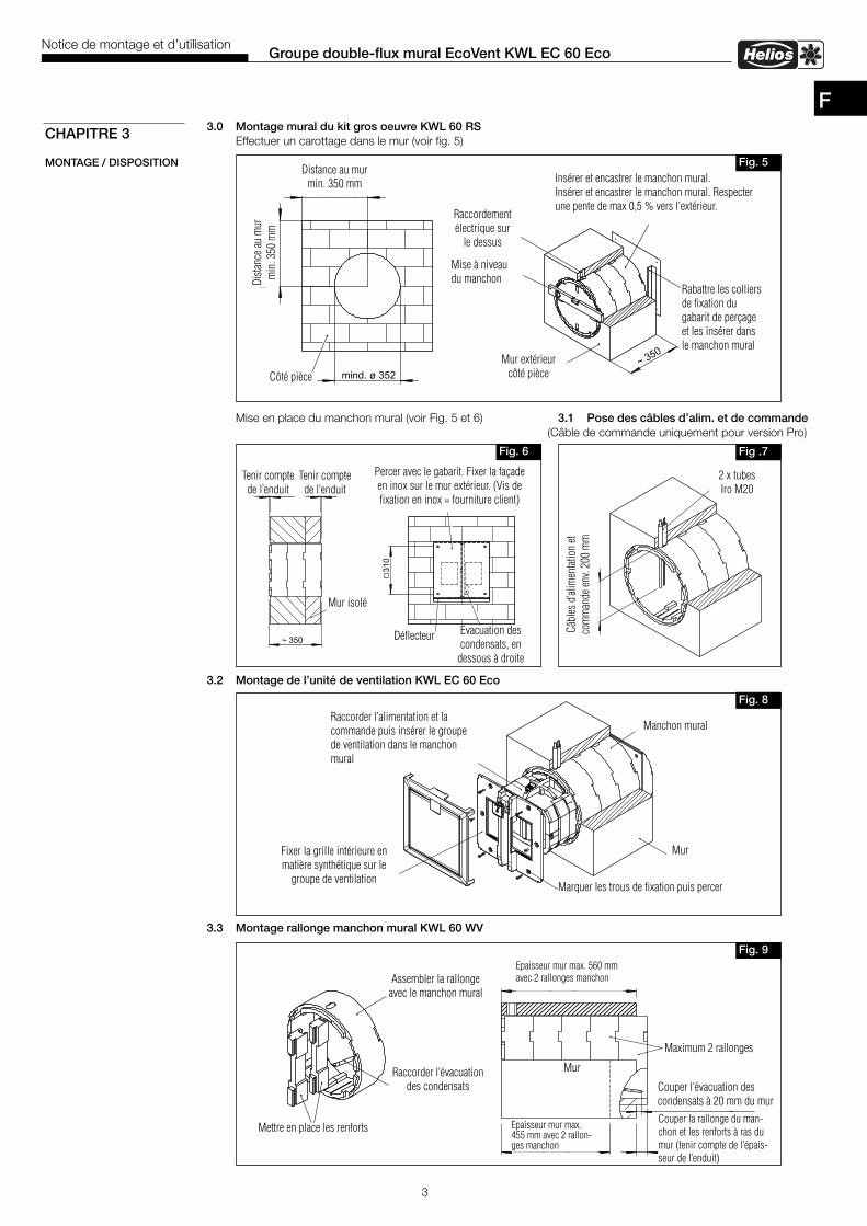
F3.0 Montage mural du kit gros oeuvre KWL 60 RS
Effectuer un carottage dans le mur (voir fig. 5)
Mise en place du manchon mural (voir Fig. 5 et 6) 3.1 Pose des câbles d’alim. et de commande(Câble de commande uniquement pour version Pro)
3.2 Montage de l’unité de ventilation KWL EC 60 Eco
3.3 Montage rallonge manchon mural KWL 60 WV
CHAPITRE 3
MONTAGE / DISPOSITION Fig. 5
Fig. 6 Fig .7
Fig. 9
Fig. 8
Distance au murmin. 350 mm
Côté pièce
Dist
ance
aum
urm
in.3
50m
m
Raccordementélectrique sur
le dessus
Mise à niveaudu manchon
Mur extérieurcôté pièce
Tenir comptede l’enduit
Tenir comptede l’enduit
Mur isolé
Evacuation descondensats, en
dessous à droite
2 x tubesIro M20
Câbl
esd’
alim
enta
tion
etco
mm
ande
env.
200
mm
Raccorder l’alimentation et lacommande puis insérer le groupede ventilation dans le manchonmural
Manchon mural
MurFixer la grille intérieure enmatière synthétique sur le
groupe de ventilation
Assembler la rallongeavec le manchon mural
Raccorder l’évacuationdes condensats
Mettre en place les renforts
Mur
Maximum 2 rallonges
Couper l’évacuation descondensats à 20 mm du mur
Couper la rallonge du man-chon et les renforts à ras dumur (tenir compte de l’épais-seur de l’enduit)
Insérer et encastrer le manchon mural.Insérer et encastrer le manchon mural. Respecterune pente de max 0,5 % vers l'extérieur.
Rabattre les colliersde fixation dugabarit de perçageet les insérer dansle manchon mural
Percer avec le gabarit. Fixer la façadeen inox sur le mur extérieur. (Vis defixation en inox = fourniture client)
Groupe double-flux mural EcoVent KWL EC 60 EcoNotice de montage et d’utilisation
Déflecteur
Marquer les trous de fixation puis percer
Epaisseur mur max. 560 mmavec 2 rallonges manchon
Epaisseur mur max.455 mm avec 2 rallon-ges manchon

3.4 Montage entretoise pour murs < 350 mm KWL 60 DR
4.0 Raccordement électriqueMettre impérativement l’appareil hors tension avant tous travaux d’entretien ou à l’ouverture du boîtier decommande! Le branchement électrique doit être réalisé, conformément aux schémas de raccordement ci-des-sous, uniquement par un électricien qualifié.Les normes et consignes de sécurité (par exemple DIN VDE 0100), ainsi que la norme C15 100 doivent impérativementêtre respectées.
4.1 Schéma électrique SS-949 pour KWL EC 60 Eco
4.2 Commande à distance KWL 60 BUA speed controller KWL 60 BU (for flush or surface mounted installation) controls the EcoVent unit. It allows a 3-speedoperation. A control cable (3 m) with RJ 12 plugs is enclosed by default with the speed controller for easy installation(function see matrix)
Dip-switch 1 = max step 45/60 m3/hDip-switch 2 = step 0, enable/disable
4
F
IMPORTANT �
CHAPITRE 4
RACCORDEMENTELECTRIQUE
SS-932
Fig.10
Emboîter la virolesur le manchon mural
Raccorder l’évacuationdes condensats
Fixer l’entretoise sur lemur extérieur (vis etchevilles fournitureclient)Mettre en place les renforts
Couper le manchon mural et sonrenfort au ras de l’entretoise
EntretoiseMur
Couper l’évacuation descondensats à 20 mmde l’entretoise
Groupe double-flux mural EcoVent KWL EC 60 EcoNotice de montage et d’utilisation
Fig.12
KWL EC 60 Eco
L1 N
Optional:Bauseitiger
On/off switchTrennschalter /
VDE 0700 T1 7.12.2
Signal derFeuerstätte,siehe MBV-
Montage undBetriebsvorschrift
Optional:Bauseits beiRaumluft-abhängigenFeuerstättenzu erstellen !
L
N
2 x 1,5mm²
85122 001 SS-949 19.04.10
KWL 60 BUArt.Nr. 84680
3 x 0,5mm²
com12
L N TR-PR
ITR
-PRI
TR-SE
CTR
-SEC
+ AB - + ZU -
T100mA/250V
com12
1-2-3Com-1 Com-2
123
KWL 60 BU1 2 3DIP-Schalter
1 2off offoff onon offon on
Drehzahlstufe0011
1 31 42 32 4off
on1 2
Fig.11
side switch
Power setting KWL 60 BUvia slide switch at the speed controller
Dip-switchNO.1
Dip-switchNO.2
step 00 m3/h
step 115 m3/h
step 230 m3/h
step 345 m3/h
step 460 m3/h
X 1 ON ON X 1 X 2 X 3
ON OFF X 1 X 2 X 3
X 2 OFF ON X 1 X 2 X 3
X 2 OFF OFF X 1 X 2 X 3x 1 factory settingx 2 Attention: Switch setting step 0: Cold outside air can stream into the building and cooling the building!

5
F5.0 Evacuation des condensats
Pendant la saison de chauffe, l’humidité de l’air repris peut condenser dans l’échangeur. Lors de bains, douches,saunas, séchage du linge ou dans les constructions neuves, l'eau contenu dans l'air ambiant peut condenserabondamment. Ces condensats doivent pouvoir être librement évacués de l’appareil vers l'extérieur.Le manchon mural doit être posé avec une pente max. de 0,5 % vers l'extérieur (voir fig. 5). Lors des travaux d’entretien,par ex. à l’automne avant la saison de chauffe, il convient de s’assurer que l’évacuation des condensats s’effectue auniveau de la façade extérieure de l’appareil et que rien n’empêche leur écoulement.
5.1 Remplacement des filtresPour procéder au remplacement des filtres, il faut retirer la partie avant de la façade intérieure. Pour ceci, souleverlégèrement le clips du haut puis basculer la façade. Ensuite retirer les filtres gauche et droite de l'appareil (voir fig. 13 a).Procéder à l'inverse pour le remontage des filtres (voir fig. 13 b).
5.2 Nettoyage – EntretienMettre impérativement l’appareil hors tension avant tous travaux d’entretien ou à l’ouverture du boîtier decommande pour éviter tout risque lié au choc électrique, aux pièces tournantes et aux surfaces chaudes.
– FiltresLe groupe double-flux KWL EC 60 est équipé de deux filtres à air classe G4, placé sur l’air rejeté et l’air soufflé(selon la norme DIN EN 1946, T.2):
• Air extérieur / Air repris:Filtre de rechange G4 ELF-KWL 60/4/4 N° Réf. 09445Filtre de rechange F7 ELF-KWL 60/7/7 N° Réf. 09446
Les filtres doivent être contrôlés régulièrement (voir affichage sur la commande à distance, réglage d’usine: cycle de6 mois), voir nettoyés en fonction du niveau d’encrassement de l’air aspiré et de l’air soufflé (risque de moisissures).Pour des raisons d’hygiène, ils doivent être remplacés tous les ans.Si les filtres sont humides ou moisis, ils doivent être impérativement remplacés dans les plus brefs délais.
CHAPITRE 5
NETTOYAGE ETENTRETIEN
ATTENTION �
Groupe double-flux mural EcoVent KWL EC 60 EcoNotice de montage et d’utilisation
fig.13a.) Démontage b.) Montage
Retirer le filtreClips
� �
Insérer lefiltre
Clips

Service und InformationD HELIOS Ventilatoren GmbH & Co · Lupfenstraße 8 · 78056 VS-Schwenningen F HELIOS Ventilateurs · Le Carré des Aviateurs · 157 avenue Charles Floquet · 93155 Le Blanc Mesnil CedexCH HELIOS Ventilatoren AG · Steinackerstraße 36 · 8902 Urdorf / Zürich GB HELIOS Ventilation Systems Ltd. · 5 Crown Gate · Wyncolls Road · Severalls Industrial Park ·A HELIOS Ventilatoren · Postfach 854 · Siemensstraße 15 · 6023 Innsbruck Colchester · Essex · CO4 9HZ
www.heliosventilatoren.deAls Referenz am Gerät griffbereit aufbewahren! Druckschrift-Nr.Please keep this manual for reference with the unit! Print-No.:Conservez cette notice à proximité de l’apapreil! N° Réf. 86667/03.11
Abb.14
KWL60
ECEco
1.2-teiligeFassade,(Art.-Nr.84687)
2.Befestigungsschrauben-Set
3.Filter(links/rechts)
4.HalteblechFassadelinks
5.HalteblechFassaderechts
6.Kreuzstromwärmetauscher
7.Axiallüfter
8.Schwingungsdäm
pferAxiallüfter
9.Fliegenschutzgitter
13.Gew
ebeband(keinErsatzteil)
14.Trafo(Art.-Nr.84679)
15.Stecker
16.Buchse(Art.-Nr.84694)
17.HauptplatineKWLEC
60Eco,(Art.-Nr.84682)
20.BedienelementK
WL60
BU,(Art.-Nr.84680)
22.Sicherung
T100mA/250V
1.Tw
o-partsindoorfacia,(Ref.N
o.84687)
2.Fixing
screws-set
3.Filter(left/right)
4.Holding
platefacialeft
5.Holding
platefaciaright
6.Cross
lowheatexchanger
7.Axialfan
8.Anti-vibrationdevice
axialfan
9.Fly-screen
13.Textiletape
(nosparepart)
14.Transformator(Ref.N
o.84679)
15.Plug
16.Jack
(Ref.N
o.84694)
17.MaincircuitboardKWLEC
60Eco(Ref.N
o.84682)
20.Speed
controllerK
WL60
BU,(Ref.N
o.84680)
22.Fuse
T100mA/250V
1.Façade
intérieureen
deux
parties(N°Réf.84687)
2.Jeude
visde
fixation
3.Filtres
(gauche/droite)
4.Tôlemaintienfaçade
gauche
5.Tôlemaintienfaçade
droite
6.Echangeurdechaleurà
fluxcroisés
7.Ventilateuraxial
8.Silentbloc
ventilateuraxial
9.Grillepare-insecte
13.Bande
collante(non
dispo.en
piècede
rechange)
14.Transformateur(N°Réf.84679)
15.Fichemâle
16.Fichefemelle(N°Réf.84694)
17.PlatineélectroniqueKWLEC
60Eco(N°Réf.84682)
20.Com
mande
àdistance
KWL60
BU,(N°Réf.84680)
22.FusibleT100mA/250V
Art.Nr.84
689