w’alw’mll. itlm)lrr - nasa · w’alw’mll. itlm)lrr “c originally issued ‘ july1942as...
TRANSCRIPT
. ~“
‘u-.,
w-
-%%==’-’
NATIONAL ADVISORY COMMITTEE FOR AERONAUTICS
W’Alw’mll. Itlm)lrr“c
ORIGINALLY ISSUED ‘July 1942as
A&winceReatz5ctedRepoZ’t
~ON OF TEE EYI!ABIUWYAND CONTROL
cHARAc!T!ERIsmosOF JKumAms FRoM lms!rs
OF POWEKEDMODEIS
By IsidoreG.”Recantand RobertS. EManaon
Ian@leyMemorial AeronauticalLaborahoqyLm@ey Field,Ta.
WASHINGTON
‘NACA WARTIME REPORTS arereprintsofpapersoriginallyissuedtoproviderapiddistributionofadvanceresearchresultstoanauthorizedgrouprequiringthemforthewareffort.Theywerepre-viouslyheldunderasecuritystatusbutarenowunclassified.Some ofthesereportswerenottech-nicallyedited.Allhavebeenrepretiucedwithoutchangeinordertoexpeditegeneraldistribution.
—L -710
https://ntrs.nasa.gov/search.jsp?R=19930092509 2018-12-02T00:11:26+00:00Z
->4.
.-
_. ——_. _... ——— ——
3 11760135440037—...– —— –.–-––-—————-~
N:.!!10NJU ADV1 SORY COIWITI!EX 3?OR AERONAUT 10S
——
RX!STRICT.ED REPORT!
THE G?ABILITY AND C03TTROL
U.
,:.
..
~ sentd in part II. Inptnrt IIT Pwre give.n the results of.$4”*. soroe tests of c. typi ccl yowercd mod..el as well as n d.i.s-
cussion of the effects of powor on stability.
. .l?OiKBIRCGNDI!IIONS.,.
.;. Genero.1 Conditions
A pi’erequisite for the Lcvelopnent of a sr.ti~facto~yoporatiag teclmiquc for powcz’~d-mot.el tests is the uclcc-tion of the airT)lanc ~owcr co:lilitions i>lat should ?36 Sifilu-‘lated, 1~.asmuch as the adverse. e-ff.ectsof power on thech.a72.cterist5.cs of tk.e
.airplano k’esult frow. the propeller
slipstream and the direct ~rO~JC~~.er i’orcos, reproduction% of the power conditions for which the slipstream vel.oci- ,,
ties anti i3ro;?eller force~ are .f;reate:jtwill be flesirable. ‘As the -sirmlanc often oper.akes without pon~er? that is$
wi.tb-the ~~ropeiler wind.milling,*6 and may have unsatisfac-tory cilare,cte~istics i.nthis condition, the windmillfng
!i!hepro-oel.ldr-removodst,ate mst also be j.nvestigated..aondi.tion is never cncountcrccl in flight, l)i~tdata forthir$ condition are always d.csira%~e for purposes of com-parison.
“-
.*.
Longitudinal Characteristics,,
The airplane in..nornal flight may operate. over its.,.speed range with any one of sovcraj. p,ower conditions
including level-”flight powc~, constailt, ang}.c-of-clim?l.powcr, constant pcwcr,’ aild idling engines. Wi”nd-tunn c1dati. nay b~ ol)taincd either by siimlating ihc appropriatepower condition on thc i~odcl throughout its ailgl~-of- *attack range or .by repcatin<; the .anglc-of-tittack t,CsiS atScvoral ve,luo.sof ‘Con.stailtthrust cocffiei.cgt ,and tlICn-cross-plotting to tti~)desired t~lr~sk C(jCffiCfLOilt (POVOYcondiiioil) at each lift cocfficicnt, .JLlthOUgh this COil-
st.ant t’hrust.Jicthod of test proccdurc .is vcrj- sirrple, thonu.ah~r cf tests ncc”os~arj”~.j,’dtho la~or i~~~olvcd. in cro~s-
plotting the results ri~,k~sit “undcsira”olc.
Of tho sovcral r.il?plai10 power co~d.itions previouslymentioned, the constant power condition is most ~enerallysatisfactory for routine invest~:;ations, It reyreseilts. a.very frequent condition in flight$ is quite readily re-

4P
.
.
. .
,.
. .
5
-.
.-
--
-. .
when maximumto detcri~i:~e
-power 5.s n_pplieJ., it is considered desirable
tk~e str.3ility and. control characteristics at
tho flight conditio~ of fullmr~?,tfld(or take-off ) power asthe fiiostsevere case to be encountorcd. The axial slip-stream velocity correspond-ing to a given powey conditionis lar~ost when the air density is grer.test; thus the max-imum adverse power effects ~,il.1usually, ‘ijeencounteredwith full-rated Dower at sea-level altitude, wilere the airis nest densoe ‘,
The stability characteristics of the airplane shouldalso be checked. at one or more intermediate power condi-tions becaus’e there are po~sible ,arrailgeriem-tsof aj.rmlplanes for which the nst effects of power are ~te.bilizlngbJTor example, the longit~ldinal, stability is increased bypower if the’ thrust axis is f:i.renough alove th.o center ofg?avity. Thus, ihe .p&r~iC.l-potier co~df~fo~ np.jybc th~crittcal condition, .’
Pr4,i*tid._pOv.r6?l?tests are 7.1s0 necessary in order toobtain ‘che Iongitudirial-st a.biiity cha.ractoristics at vRr-ious values of constant thrust coeificien”t by propercross-plotting. The stal)il:ty charc.ctoristics for con-st,r.ntthrust conditions det6r.mine the power-on sta.-oilitjrdcriva.tivcs. c.nd must therefore be used in computing themotions of the airplane.
As wns showlI in figure 2, the windmilling or idlinspropeller hns a rather powerfnl destabilizing influence.Inasmuch 2.s the propeller is frequently idled during theoporati.on of the air;?lanos, it is ;loccssary to investi-gate tho stability cha.racteristij.s for this condition ofpropcllor operation. I,n tho cv,se of idling propeller,the air :;tre~wmforcos tfi.epropc]-10r to rotate P.gcainstth~en~ine friction-forces. Thus$ the ifiechanical condit;onof the’engine, tho fli~;ht speed, and th,c setting of thepropeller -speed mechar.is]~ determine the anount of nega-tive thrust developed by the propeller. Tests inilicato~howover, that the ai~ount of negative thrizst is n“ot i~erycritical for the usual flight conditions, For tes+s ofCJOFICISof dive bomlers with “~raking Tropfillers, ttie prolklem may he more critical and some attem-pt- to sir~ula.tctheexact air-p].ane engine-propeller characteristics for tb.cseconditions should piaolably be made.
,,
6..
. .
-.
. .
w..
7-s
“
.s
.-.
-.
“.
L.
.--.
-.
.-
,..
.=
9
..
-.
maneuvers, the required elevator deflections may be un-obta.ina’ble because the stick forces exce~d the pil’o%;.sstrength (reference 3). In a stall or spin, the elevatoreffectiveness may be inadequate or t}.e stick forces toohigh fey, recovery. In any flight attitude with freo con-trols, the stability will depend upon the trim-tab s~t-ting and may l)e Undesirably low.
Necessarv tests.- In many cases~ fortunately, the same-.— ——:— .— —series of test’s may be used to estimate the characteristicsof the airplar.e for several of tk~ pyobablo critical Cen-d.itions alreaiiy described as voll as to iletermine certainmodel characteristics t-hat must be used. to correct thetun,nol data to flight conditions. The ope.ratin~ proced.urowill be dcscribcd in part 11. The lift, the drag, thepitching inomont, the power yaraiijctcrs - thrust coofficicnt,torque Coofficitint, Zid.-r:sn.cc-,!lia.mot 01’ r.e.tio , cfficioncy,and %lade e.nglo - anti tho olcvator bingo .momants arc! riicas-urod at ve.r~ous angltjs of R.tt:2,ck from aluost ZCTO lift %0the stall for several. cl:?vator and stabilizer, scttir.gs ~oi-the various .mod.ol and powor cond,itiofis to ho invcstigatod.A fo,w clcv~,tor tests S-hOUld bo run- with the model simul:~t-ing tk.o clim~ing and t’kc gl~ding conditions at angles OYattack a-oovo th.o Stall to dcit:rmiilc the olcvator and sta-bility charactcr~stics in c stall or a spin, and. Sore-o el-evator tests sy.Ould be run at n.cgative lift coefficient’sto doterr.i.ne the characteristics for conditions simu’lat-in~ inverted flight flor highly m~,neuvcrable airplanes.The effect of the trim ta’b upon the stick-forco char~,ctel*-istics for somo of the conditions mus$ also be checked,Elevc.io2- fyee tests need Pot ye run, “~ecaase th~ hin”~emonen-ts are measured ir- the elevator tests afid.,by proper”cross-~lotting$ the elevator-free ch~ractcristics na;r 30determined. If it is iwyossible to measure the hinge no-,ments, ~~owever, elevator-free tests ,should.l~e m~.d.eo TheCffect of trim-t~.b setting upon the elevator-free chzrac-‘ceristi.cs should be ch.ecketi.
wail-removed tests should be ms.d.o‘to facilits.te analy-sis of the data, although such- tests are not a-osolutolynecessary. Those tail-rer.oved tests arc high-ly ir.”portantiif the original tail surfaces arc unsatisx’e.ctory and must’be redcsi~;nod. Air-flow surveys Lt the tail region arcalso vcr;r clcsiratlo.
~ the Sta~ilize~* t~StS isThe nurpose o. twofold:first, to-d.otermino the staiilizor setting rcquirocl totrim the airplano in the cruising attitUdC, and second, to
--
determine tht3stalli.?.izereffectiveness t)Cg./~itfor the
.
. .
“,4-
,,* *,-
11
“.
. .,/J
. .
da~c. C03?rE?Ctly~it is necessary tO determine the static-stmbility characteristics foi~ trim conditions since the
static stability does depend upon the i,nitial tail load
(elevator setting) for power-on tests in which constant
pOWer operation is used. The LISUR1 measure of staticlongitudinal stability is the slope of tke pitching-momontcl.l~\~~ dCm/d~Lo The slope of the pitching-rnornent curve
dCi~/dCL I,,USt therefore le determined a.t cm * 0 for eachelevator scttin$; tested a,nd then plotted as a function ofthe trim lift coefficient. Another ti!easure of static lon-gitudinal stability is, simply, the elevator angle re-quired to trii~ the airplaile over the lift range, The twomeasures of static stability are closoly related. Forqualitative work the elevator p.ove~L~~nt rec~uirett to trimthe airplane over the cow.pletc speed rai~ge is Dot only agood measure of stability but also ,allows direct compari-son with flight bocausc it is readily determined in flighttests.
Tho stick-free stability characteristics should bedetormincd for trimw.ed conditions (trim by means of tabs)also. qlle plot of elevator angle for trim as a functionof lift coefficient such as is used to doftne the stick-fixed characteristics will not define the stick-free char-acteristics, however, %ecause the curves would be thesame (stick free or stick fixed) for any given model orpower condition, !lhe actual slo~es of.the pitching-momentcurves at Cm = O (for the trim-tab setting for Ghe = O)
must tie used for the analysis. For puryoses of comparisonit will be advantageous to have the slopes d~m/dCL forthe stick-fixed condition also, Thus it will usually ‘oesimpler to analyze the data, for static stability and fortrim if it is summarized hy plottiag elevator angle re-quired to trim against lift coefficient for each model andpower condit$on tested aitcl for each, center-of-gravity lo-cation to be used. and also by plotting the.trimned slopesdCm/dC~ as functions of lift coefficient for tQe stick=-free and the stick-fixed conditions,
?If it is ile~ired to calculate either the,notions of
the airplane or its short-period dynamic-stability charac-teristics, it will be necessary to cross-plot the constant-power pitqhing-monent curves to obtain constant-thrustpitching-moment curves. The slope of the constant-thrustcurves is acm/&t (the chango in pitching nouent due onlyto a chango in a.i~gle of attack), and tho slope of theconstant-powor curves iS dcn/dm (th~ conploto change in
*..
.-
0.
..
.%
-.
. ,..
.
cient power or because the control forces are too high topernit large deflections, it nay not be possible ;0 hold
the airplane at zero yaw when. operating with. unsy~l!.1otricr-1power, Single-engine airplanes are also likely toexperi-
.. ence trou”ols in this respect because of slipstrea~m’rota-tion, In some cases, full rudder ig required to hold t~oairplane at zero yaw with flaps down ~and full PowOrO q~~:~
chnnges in roll caused by motor torque have 21s0 beenfound- objection~,hle on several airplanes. All those tri~.1chan~es c,re ;.lostmarked in those ’.fligh~ conditions inwhich the speed is IOW and tk.e power applied is Iarges
yaw, the flight condition at whick the ,diroctional Stabil-ity is ‘:~o~tlikely to be uns:~tisfactory is the landingcondition when the propoller 5.s windmilling. At largo rLn-
glcs of yaw with tho rudder fixed or free, the dircctionr.1cha’ractoristics .nro,proba%ly tho least satisfactory underthe hi.gh-th~ust condition.
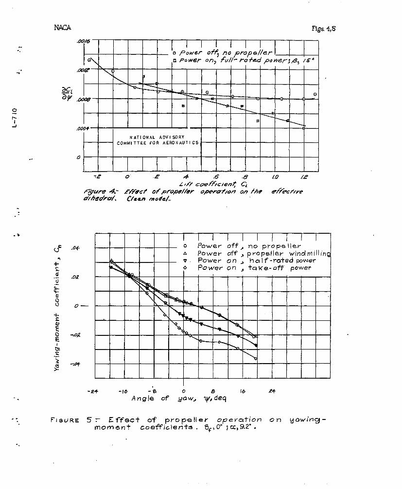
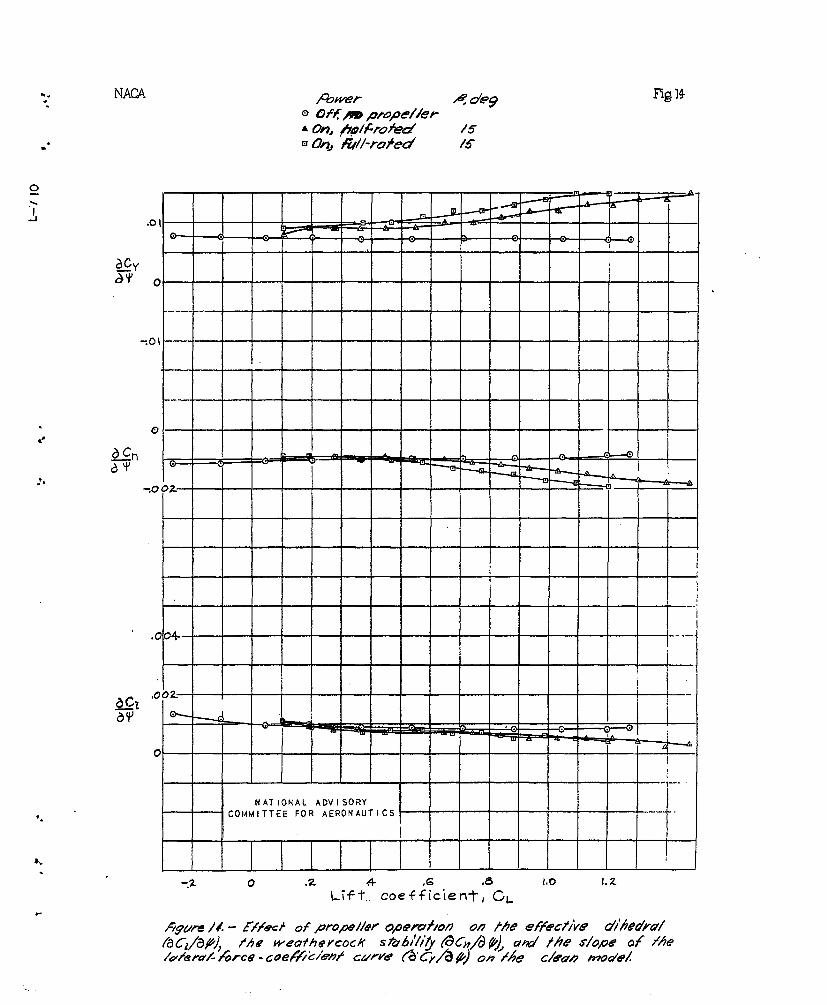
.. Tho slope of th,c rolling-noincnt curve ijC~/i3* is aileasure of the effective dihcdrcllj a. value ‘of about 0.0002being equivalent to 1° of dihedral. (See refcrcncc 6.)The influcnco of power on tho dihedral is quite narkedoFor one singlo-cn~ine nodol tested in tho 7- %y 10-foottunnel the cffectivo dihedral was roducod 10° IIY alout 70-
. pcrccnt rated power applied in the land-ing condition.Multicngin-o :.lodolsusually ‘do not lose as nuch dikcdra.1Cffoct ~hon ~)o~~cris applied as single-on~inc nodclso !lhc
l,,oss.in cffectivc dib-edral ce.used by -power is usaally
gi*eatest for conditions of slow-flight spocd. l:~ithflaps do-flcctod’ and. with high powor.
Whc stability anti trin cliaractcristics r.rc ~ff.octc~.~~r the direction of rOtr,tioQ of the propellers Of r.iulti-cngino ,airplancs. It iS thus important to dctcruipo thC
node of rotation givin}? the aost desirnble char~cteristics.,Since longitudinal zta’oility characteristics are nlso af-fecte(7-,a conpronise :;Cay%e nccessr.ryb
An airplane, tO he sr.tisfactory under all con~.i~ions~should possess not only static stability hut dy~lanic str.- :bilityo Dynr.r.licstability requires thnt the we,athercockstalility and the effective ‘.iheiira.llie within certainlicits. These li;lits ~;,epe:ldZ~Ot orJIY ofl the various aero-d~.na~~i~ cha~acteristics of the airplane but al SO upon the
-.
thc2 control-surface chmr.ctsrist!. cs for contro3.-frecfli~ht . I)esiraljla linit~ of the staticwstabflity criteri-
ons for P, particular airplane rAay ie esti!.ated by use of
references ‘7, 8$ and 9. Inasnuch as the stntic-stabilitycharacteristics vary through the flight range, it will benecessa~y to tieteraine whether these characteristics lie
within the required Iinits for each con~.itiofi of fligilt9
..
..
. .
-..
. .
15..-
.3
1.
.x.
the tail. These tests greatly simplify the problem of re-designing the tail su~f~.ces, ~-f~~~~esigning is necessary.
Presentation and analysis Qf data. - The lateZ’al”stability data obtained. fr,o~~the 1,odel tests shou].dbeanalyzed “for steady-state ~~im.~ed-fli~ht cond3.tions. Iti..sdifficult tc ~“~~taindata for tk~ model trimmed with re-spect to all th.’ee axes: pitch, r[,119 and yaw” There raretWO ~ractical “.lvthcds of obtai,nin~ data for triinmed~corldf-.tions. “
one !IIei;k.od is to transfer the. data from the usualwind-tunnel .kalar.ce axes (tihe wind a-ws) to sorno“Othersystem of’ axes such that the deflec+i.cn of any Ore Gf thethree controls will affect o~ly tl.a n~ments a“bcut theaxis that control fs ncrmally desi$h~d. to affect and w:.11net appreciably affect the moments ~litcuteither Of theotb.er two axes. For example$ in cr~$r to determine theeffective dihedral (~CZ/Eho) it is :~.ecessary tc have themodel trimmed in pitch and ir. yaw;’ ly’;herwise~ componentsof pitchiq mo~lei~ta~d of ~awi.ng monl.m.t will. be presentin the rolling Moment. If’, kowever9 the data arc trans-ferred to a system Gf body axes SUC;.1that the x Wis i.ieSin the plane of’ symm.etry~ r.o compofieqlt of pitching moment~.~qou-ttbJe ~< axis due to ele-~a~o~ deflection cjah affeCt
the rcl-ling moment about, the X axis. If the X axis notoniy lies in the plane of synunetry but: also passes throughthe center of pressure cf the ver’tic::.~~tail surface, ”r10component of yawing moment about the Z azzi.sdue to rudder,def’lection can affect the rollin~ r.ofi:e;.ltabout the X axis.
After the trar.sfcr has been ~.ade$ tke slopes aq+q -and ac ~/a* ~-~y be easily ~~ter~ined fcr trim COi2dit10P.S,becmse ‘the other moments l~ave no effect about these axes.IMr most a~-rplane mcxiels the ccxnponemts Gf ‘rOllin~ Jm’H2tdue to rudder deflection are rather smal.2.$becmse’the cen-ter of pressure of the tail is usually fairly near the rel-ative wind vector through the center of gravity~ at leastf’orthe critical case of.minimum speed- (with hi,~h th~stcoefficients). Th.us~the compcm.ent of rollin~ nmnent dueto rudder deflection may generally be ne~t:l.octedand it willbe necessary only tc)transfer the data to the so-called
-. stability axes instead of to the body axes. Transferringthe data to the stability axes is simpler Gb.antransferringthem to the body axes. The stability axefi are a system of..
. sx.es;-nwhich the X axis is the i.ntersect:.cmof ~he planeof’symmetry of the airplane with a plane K,erpendicular to
-.
the plain” of synunetryand parallel with the relative winddi?Wction, the ‘Yaxis is nsrpendicular to the pl~.e ofs:jflmetry~and.the Z axis is in Me p~ane of symnetry amd;:.c~’pcxwilcular to the x axis. It must be enphas~.zcd ihzt“Khcuse of this system of axes corrects the data for ur.-trimm.ticl’piGching moments only. iH20thGl? advm.t age of the‘ij-fi~ of” the. stability axes :.st,hst this systcm of axes isnest easily used for dynamic -stub j.lity- calclilations. For
the coriventence of the tunnel operators the “Dasic ‘tram-
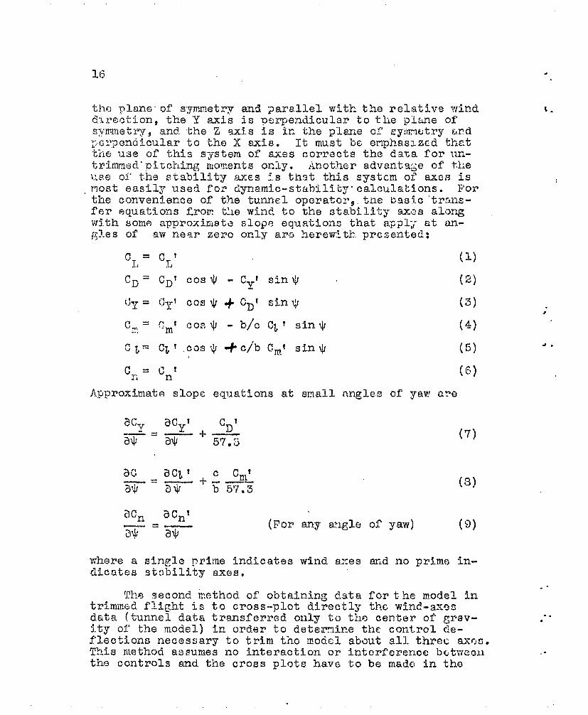
f’er equations ~ro~. the wind to the stability axi~~ along‘withsome approxiriiate slope equations that aFp~Ly at a~-fl~me& of lawnear zero oP.ly arc herew~tk, presented:
(3)
N2n acnt(For any angle of yaw)
—= T-ZI*
(7)
(3)
(9]
t.
. .ThE?second k.cthod of obtaining clata for t.he model in
trimmed,f’li@t is to cross-plot directly the wind-axesdata (tunnel data transferred only to the center of ~rav-it”yof the model) in order to deternir?.ethe control de-f’l:ctions :ecesfiary to trim tibc flodcl
ThI.s methoci assumes no interaction or
tlm controls and the cross plots have
-..
..
1’7
style of successive approximations. The labor involved,
howevery will usually bo less than the labor inv.olvo,d “in
th~ tra:isfer to the stability axes beforo the cross plots~nre made . (Tho cross plots must bc made to finalyze tht?data properly.)
~h~ plots of the confjrol-surf~CC doflcction ncccss~wrY
~~to” trim the model at each angle of stcz,dy sidcslip nro notonly convmicnt summr.ry-plotsbccnusc they give a directncrxurc of the stability, control, c.ndtrin.characteris-tics but also nay be d5.rcctly compnrod.with results offlight tests. The nr~glc Of bank neccssnry to counteractthe lateral force mc,y .a’lso.be coirtputcd for comparison. withthe r.nglc of br.nk mcas”urcd du,ring flight tests, if iic-
siicd.. Part of the r~casi~rod lr..toral force is due tc therudder setting, and the VP.lUC of the l,atcrr.1 force uscdeonscquontly depends upon the contrcl dcfl’cctions requiredfor trim,
In order to calculate the notions of the r,irplane r.ndthe dynr.nicrnstability characteristics, it is necessary ichnve the trim slcpes of iY,e rolling-uonent, yn.wing-zlonentyLand Ia.tez-.nl-force curves near zero yaw. !l?hese slopes nreto be obtained with respect to the stability axes but III?.Yhe 03t,zined fron the original wind-axes dati,.r,nd correctedto the stability axes hy use of the r.pproxirx.tc slope for-r~ulr.spreviously given.
/
should be detornincd n.%cutthe sta3ility axes. For prc.c-tical purposes wind-nxes dc,ta~i~.y“be used provided thr.t therolling effectiveness of the Iatcral controls is detcr-
r,ined at zero yaw ivhere the wind aizd”stability axes arc thesane , since the yawing nor:e~-t 5.s alimys the same about eit-her the wind OY the sta%iliiy axes. These data are of
value lcth for comparison of static data &fid fol’dynamic-stability and resulting-notica calculations. These calcu-lations must be made if it is desired to estiriate the ef-fectiveness of the controi surface in producing tkc do-
sired notions of an ~irplafie teca’!!so the coupling o.f the
yawing and rolling motions resv-ltin~~ frcn solall corLtrol
deflcctioi~s may generate filo.iioilsopposite to those tz’at--the co~~trol doflcctions woro designed tc produce. ~~~ pc- I
riod ai~d dL~;~L~in~ of .-..any oscll~a~zc-n s.hou.ldbc ostinato d
... for tho various flight ccnditionso
. .
18.
:.
Sunma,ry of Tests Reo,uired
. .
-..
... .
..-
*
“..,.
. 19
fo.ctors are reproduced, re~,ults that are correct for allprnctical purposes may 30 obtained.
In practically all power-off wind-tunnel stabilitYinvcstigtn.tion the effects of Reynolds- numlery tur’OUlence~surface uoughness, interference of omitted parts, Machnumber , etc. are ignored. ‘i!hoonly criterion of simili-tude that is usually net is that the model be built tOscale with only a few omitted parts. In making power-on
tests the only important additional criterion of simili-tude is the.t the relr.tive slipstream velocities be the sameon the model ,as on the full-scale airplane. If the slip=-‘strean is reproduced; the propeller forces will automatic-ally he reprod’iced because the prop.el-ler forces a~~ equalto the increcasc in mor,entum of th.c,,a,irin the slipstrcanoIt would require a detailed air-flow survey of thO L“egionin and near the slipstreari of both tho model and the air,+pln.ne to &etermifie properly whether the slipstream h~.sbeenreproduced. SUCh surveys are impractical and it becomesnecessary to determine some simple criterions for reproduc-ing the slipstream.
!i?hcimportant airplane slipstream ckractcristics mw
be considez’ed reproduced on the model when the.tlxcust co-cfficienk$ the torouo cociXiQQQt~ and the Yormal-forcP~o@~,z$.i~t of t~:e modol are tho same as tho%”dW’”~h”&”air-p~c.ne. Those criterions of similitude are based upon elo-mcntary moncntun theory, which indicates that tho axia~
sl.ipstrcan velocity ratio is n function of the thrust co-
cfficiont, the ratio of the tangential to the axial veloc-
ity (~~ is proportion,nl to the ratio of thoior~ue coefficient to the thrust coc.fficients and the an-..gular direction of tb.c slipstrcr.m is a function of thenormal-force coefficient and tho thrust coefficient- Thoefficiency may 3C considci-ed a criterion of the ener~Ylost in the slipstream due to eddies, temperature rise$and altered velocity distribution.
.“-.
Fortunately, experience has shown that it is ~Lsua~lY ~not necessary to exactly re~roduce the slipstrea~i: in or- ;~der iO secure satisfactory results in most power-On Stan ;~bility investigations. The effects of each “of the varia- “j~lOS should be kept in z?ind, because experience has indi- ~~catcd that sonc of tho factors affecting these variables ,,arc relatively unimportant for sonc types of test on so~lc
The sane factors arc of utcosti inportancc for i~,airnlancseother tynos of test or for other riirpl?mo iyyc?s.
!{
/. .
-.. .
.-.
...
. .
. .,.
.
-“2
.“3
.
.-“l
“.
,.
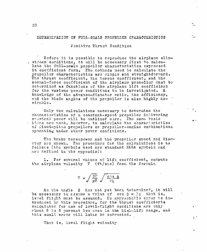
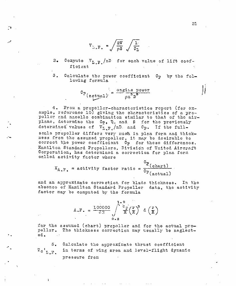
12● Compute ,YL,Fo/nD for each value of lift coef-
ficient
3, Calculate the -power coefficient Cp by the fol-lowlng formula .
4. l’rom a ~3rope7.ler-cllaractcristics report (for c?x-a.i!lple,l?ef(ci’cnce10) giving the characteristics of a pro-polle?: r.nd nacelle combination similar to that of the air-plane , detcrmino the cT, ~, and P for tho previously
deternineii- values of VT ~ ./n~ and Cp. lf the full-~.-.
scale propeller differs ?rery v.u& in ~1~.n form ,and thickn-ess from the assumed propeller, it, m~~y he dcsirahle tocorrect tmb.epower Coefficient cP for these differonccs.Hamilton Standard Propellers, Division of United AircrP;ftCorporation, has determined a correction for plan ferncalled. activity fc.ctor whore
NW(chal, t )
KA, Y, = act%vity factor ra%io =Cp
(actual)
an-d an approximate correctio~ for ‘blade thickness, In thotabsencc of Eagiilton StarLd&’d %’rope~lei’ data, the activityfactor may ‘OC coqnzted by the forr,ula
0.2
for the assv.ned (cl~art) propoller and for the actual pro-pellor. Zy-e thickness correction may usually be neglect-
● ..,
I
,
.,
. .●✎
✎✎
✎
.i 2s
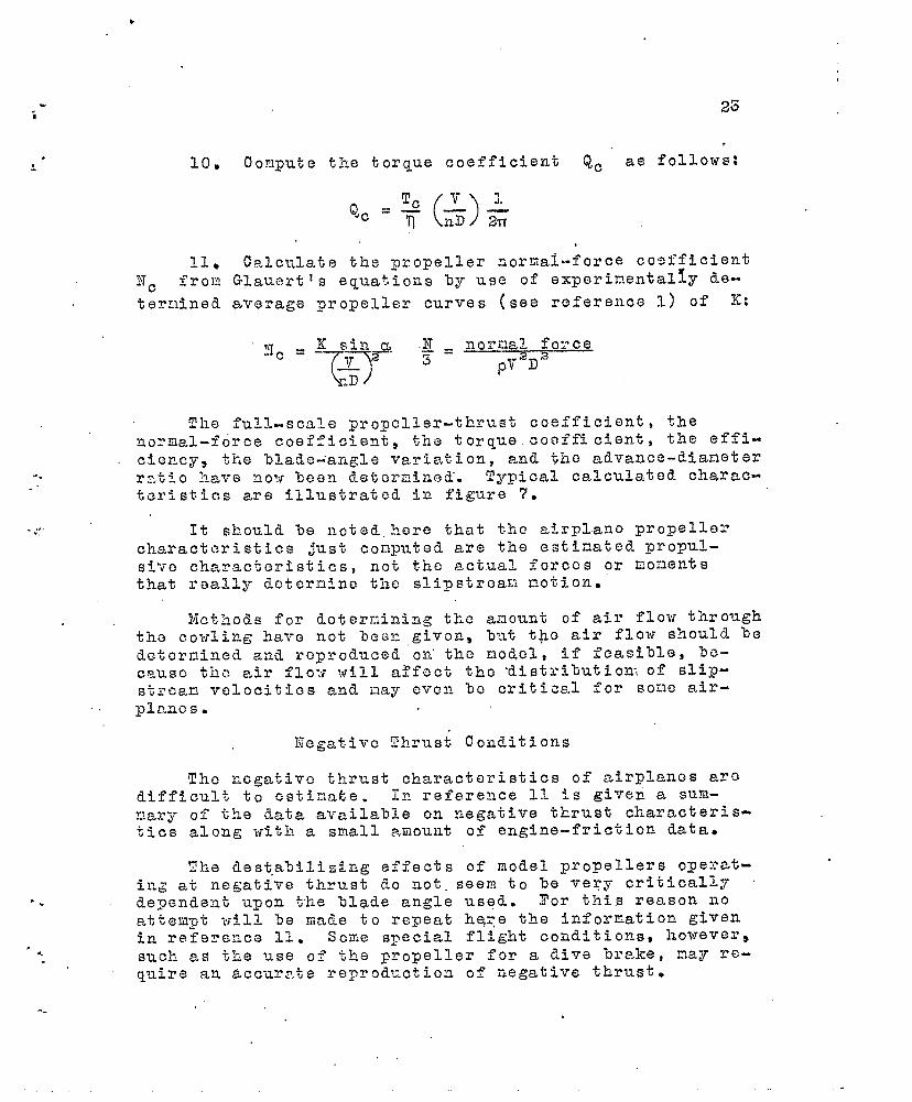
10. ~o~,lputethe torque coefficient Qc as follows:
11* calcy,la~~ the propeller normal-force coefficientN ~ frou Glaunrtls equations by use of experin.entally tle-
ternined average propeller curves (see r~ference I) Of K:
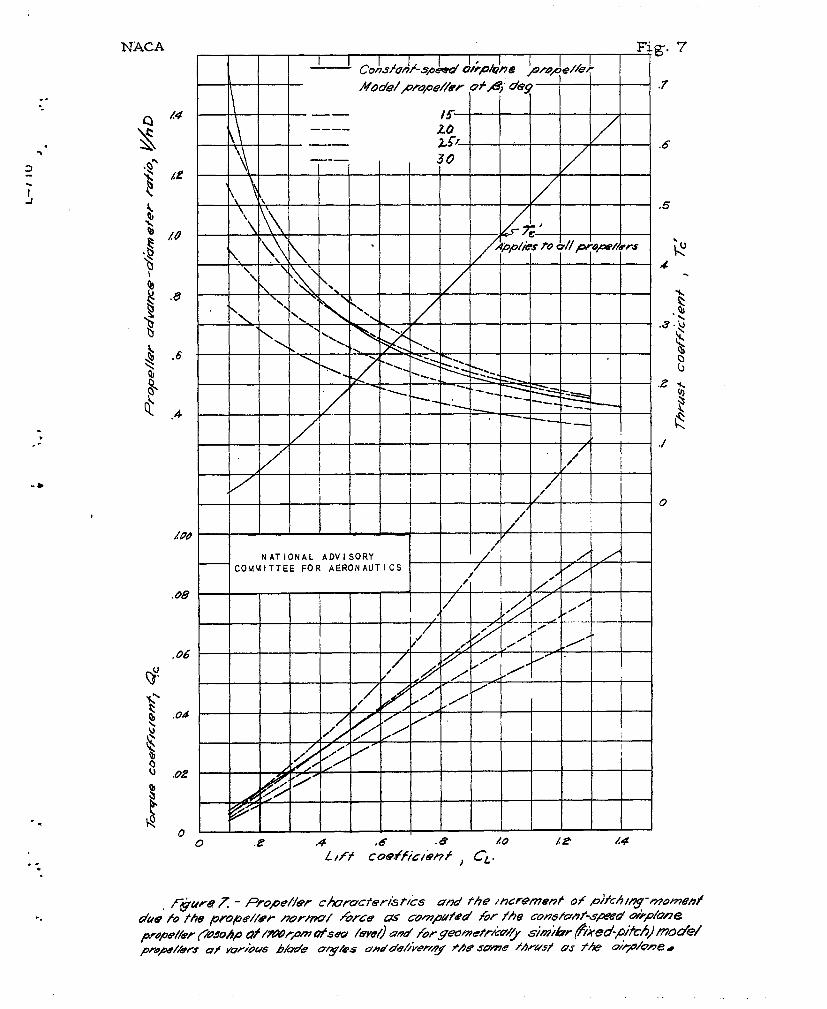
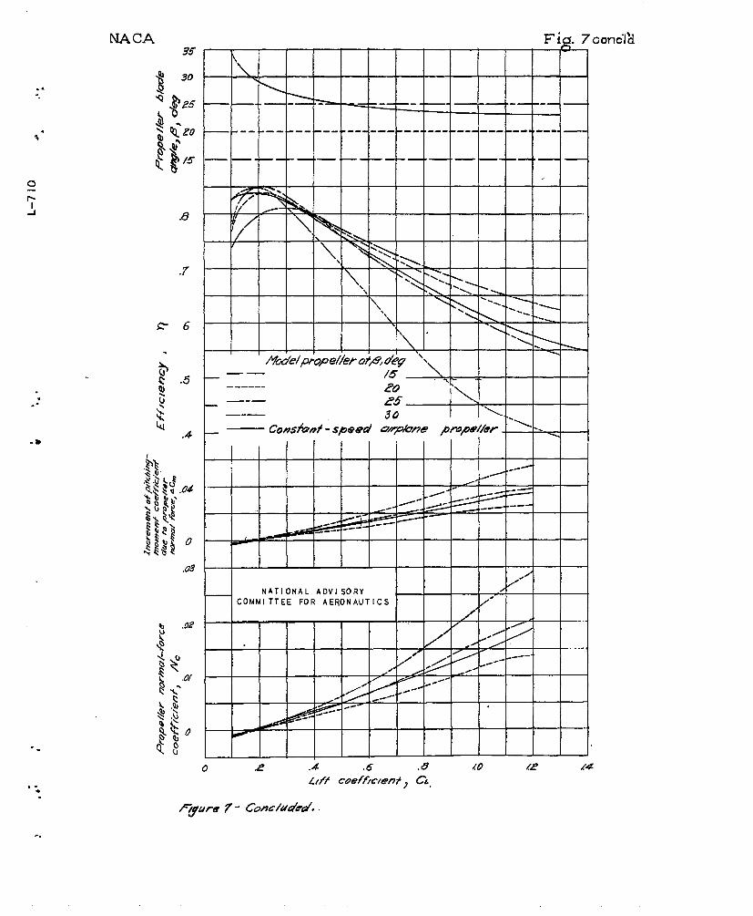
Tile full-scale propeller-thrust coefficient, theno2rLal-force coefficient, the torque coefficient, the effi-ciency the blade-angle variation, and the advaqce-dianeter
..- r:,tj-o!~a?~enow lcen detcrr~iaed’. Tymical calculated charac-..
teristics are illustrated in figure-7.
. ,.,., It should be noied. h.ere that the a?-rplano prope~le~’c’haractcristics just computed are the estinated propul-Si’ro Chcv.--acteristics, not the actual forces or ~?o~-le~tsthat r~ally deternine the slipstrea~: notion.
Negative ‘Zhrus~ Coilditions
Tho ncgativo thrust characteristics of airplanes arcdifficult. tO estin,atie. In reference 11 is given a sum-r:~t:yof the data availalle o.n negzitive thrust ckaro,ctieris-tics aiong with a small amount of engine-friction- data~
The dest,ak,ilizing effects of model propellers operat-in~ at negative thrust do not. seen to be ‘ier~’ critically’
““ dependent upon the blade e.ngle used. Tor this reason noatiernpt wIIL be made to repeat he,,e tho information givenin refs~.en.ceil. Some syecia.1flight condi.tionss hol’~e~er~
‘< such.as the use 05 the promeller for a dive %re.ke,nay re-quire an accurr.te reproduction of r~egativs tb.ruste
--
.:
25
.
...
etor m -~G&~.$lLQ, ~~.rusifi....c.~.e~ficicnt ba scd umon wi~.g,=...,..,... -........-...+..*,...=-.............,.,.,,,.,.area should bc re~r.~~,-,,$.ar. -..-t-kaa”-thc-.t.hr-U~~+...@+~~~~i-”cicnt %.ascd on disk u.
.....
OPERATOR
The ~o~t Con-rcI,ient method of determining th-e Char-
actcristlcs of the uodel. pro:ocllers is to run propcller-calibration tests :,~fththo clean model mounted in thetunnel at about zero lift, that is, to measure the cffcc-tivc thrust coefficient, the torque ccofficient,, and th~GffiCiCilCy for Vp.ricus values of ~T/nD and blade an:jlc.The effccttve thrust coei’ficfcnt basc~ On modcl wing arce,
and on dynamic pressure is dctormincii frmm the drag-scalercad,ings takeu with the -pro:p~llors cpcrating and with the.propellers rcmavcd. Thus,
alc .=
CJ) - CDpropellers removsd propellers cperatin~
.. ..:The torque coefficients are determii~ed ej.tlierindirectlyfrom cali~raticns of the model motors or directly frcmtorgue-meter readings. The efficiency may be calculatedfrom the thrust, the torque, the, motor speed, and the aiz’-
~he n~%ope~~er ncrmal-forcespeed as mess-~rcd. character- ,f~tic~ must lle calculated, no simple methcd of measuring I
them ‘being availabldc
.. .
A slight error int.chermining experimentally the pro- .peller thrust may be caused by the. fact that the effoc-tivc thrust for a given actual thrust may bC dj.ffcrOnt on “’the airplane and. on the model if tho model clcanncss ortho air-strcarn turbulence is ,~roatly different frcrn thatcf tho airplane. That is, tho Glipstrcam velocity is de-termined ly the actual tiy,rustforce - not the cffcctivcthrust - and tk.c ‘act-~al slipstrcafi values should 130 rcpro-tLuc~d,o If the tr~.nsition is f~xcd at the s~mo yoint cntkonodcl as on the airplane, this effect can be partlyoliminatcd-
Thlc “Dl,adcangle for ~~rfi.ichth-c thrust,, torque, nOrrflai-
forcc , Cmnd “efficiency charactoristi cs most nearly ‘repre-
sent the characteristics o.f the airplane ccnstani-speed
propeller i:ay be determined %y ccnparing plots of experi-
mental model- propeller d.nta with calculated full-sctalepropeller data similar to figure 7. Tlie effective thrust
-.
26? .
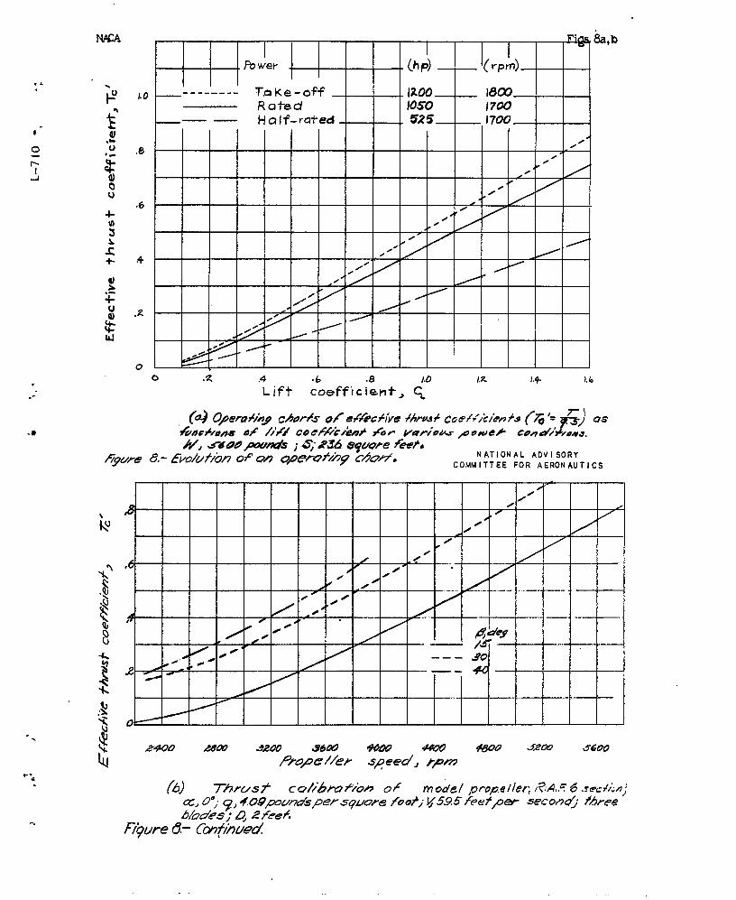
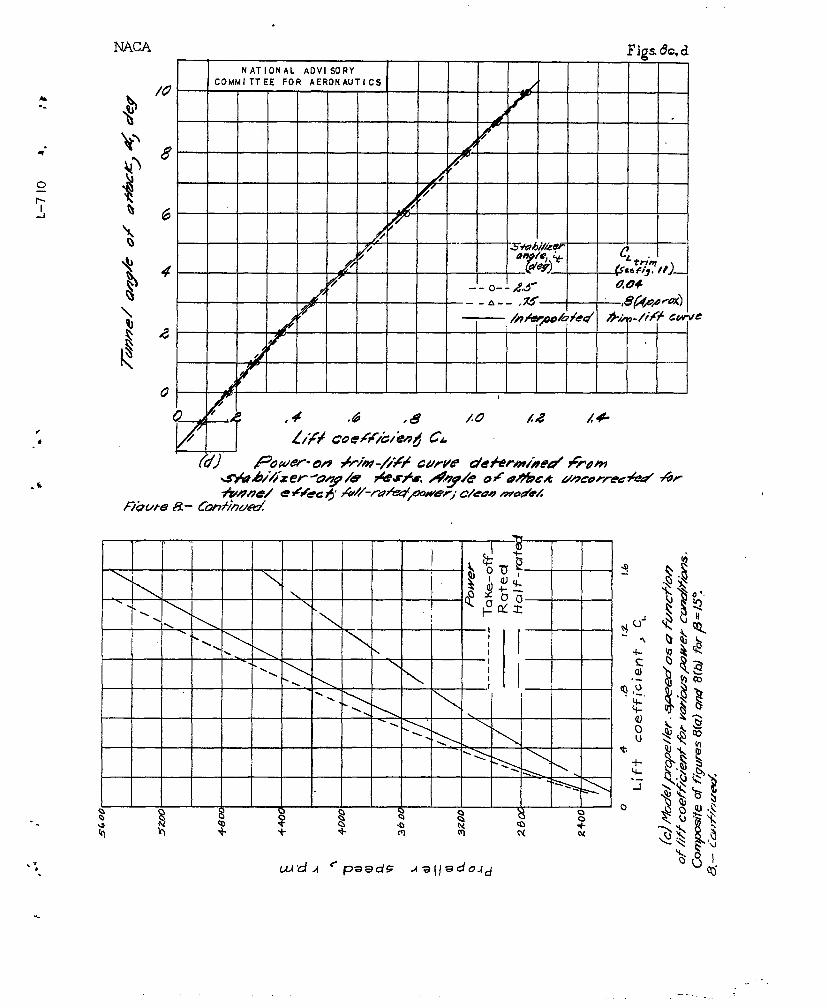
The computed airpla.fi.esft’ectivethrust coefficientsfor various lift coefficients and power conditions me~~loy~nin figure 8(t~) _ A nc~el propeller calibration isgiven in figure 8(3), and a composite (,) an.?,Cli-i’i~ures 3 .n
The conao~ite curve $d?OUS8(%) is given in figure 8(C). .promeller smeed in revolv.tions Eer nin.~te plotted c.gain:;t
lif; coefficient for a given value of tunr:el t.ynamic pr~s-
surc.
.
J.
.
----
..,
...
.. .The method of operating the propellers for yaw tests
i,’squite simiple. ‘ The model atti,t-ode is selected (high-‘sp5G& attitude, climbing attitude, landing attitude, etcO)c.nd tti.o‘propeller s:pecd corresponding to that attitude forxGrQ a?lglo of yaw is SCt and ~~i~t?.ir.~d througho~t the yr.w !
0 Z’arl&ctcstcct, Although this oporating procedure is thosimplest pos~i’ol”e, it roproduccs tho airplane-propcllcz’ 1
conditions exactly for only small. angles of yo.vre At lcu?gcr,
Mglc s of yay, the representation is not o-uite so accurate. I
“The lift coefficient usually falls off ~t moderate and at .!high angles of’yaw
$@‘“n steady-state fli,ght) and it would
1
therefore he necess J;- either to change the flight atti- ,tude or “to increase the airspeed in order to correct forthis loss in lift coefficletit at the initial arigle of at-tack. ~~:~ fact that either nethod of correcting for theloss in lift could he used by the pilot indicates the dif-ficulties encountered in trying to represent exactly the
.
“.
. .>.
-.
.,
OZ’A POW3ZREI)MODEL
a i/5-scale model of a low-wing~si,ngle-eng.lne, pursuit-type airp~ane. It was made ofmah~ogany with a hollow fuselage inn.which the motor andthe hinge-noment balances wore installed.. A threo~viewdrawing of the model is shown in figaro 1.
Test cond.j.tion.sand nroced.urc.- The tests were made.—in the NAGA 7- ‘Dy 1,0-foot ~:~indtunnel (reference’s 12” an”i13) at a dynamic press-tire of 4.09 poancls Per square foot,corres~oilding to a velocity of a-~out 40 ,miles per b-our atstandard sea-level conditions. The test Reyu-olds number,‘eased on t“nis speed and. a mean aerodynamic chord of 16.32inches was about 500,00C. The turbulence fac~or of thec+t- b37 ~0-fo~t t-~nnel is 1S67 so that tie effective R.eynOlds
n.~mler was e,-DOU% 80CI,000. T]~e test procedure was similarto that indicated in part 11.
.
xl
All. corrections are ail.d.ed‘to tunnel iLnta-
tli or~s (10), (11), and (12)
correc-
(15)
(11)
C?cgrao
. .
. .
.7a
. .
..
I
... ,,
. KESTJN! s...
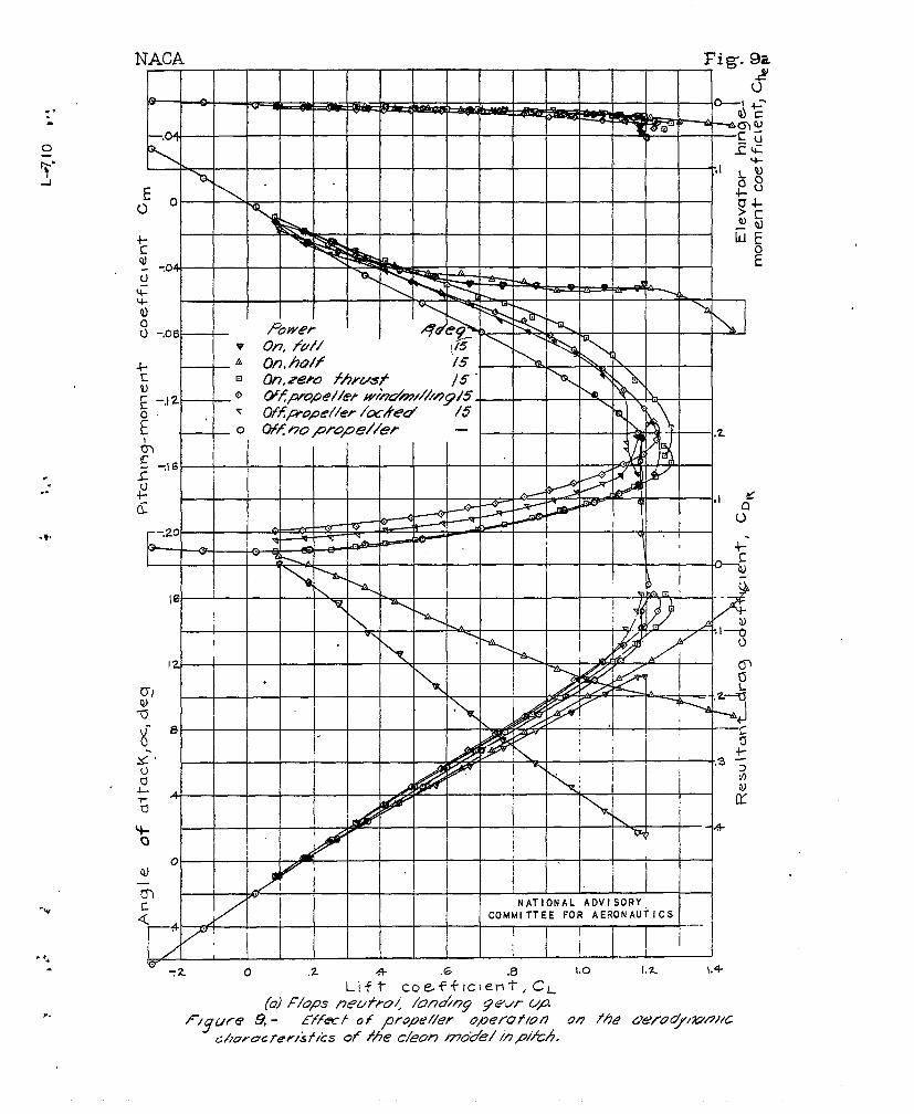
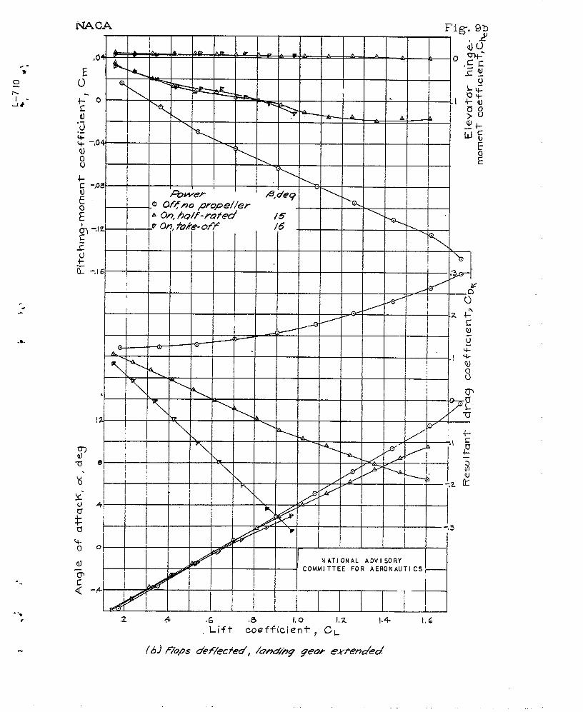
The results of the pitchmower conditions are Riven
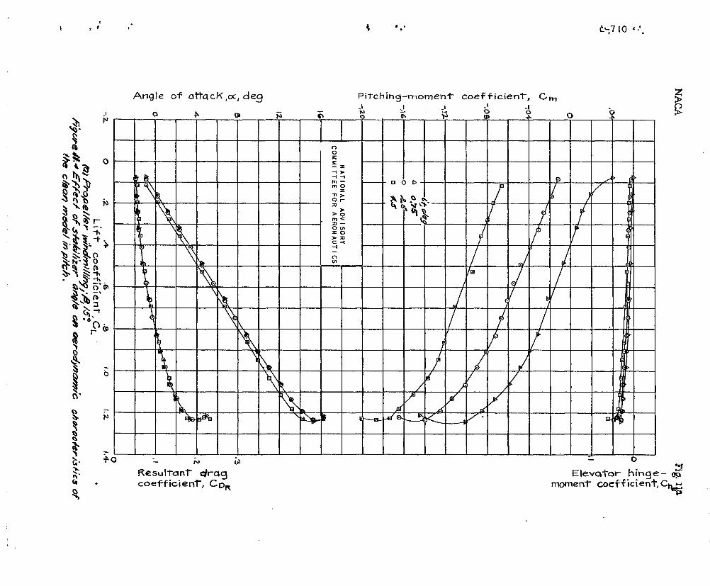
OIlaracteristics in vitch.-——tests of the uodel with various -ill f’ig-.nes9 to 12s Examination of these figures revltaisthe following facts:
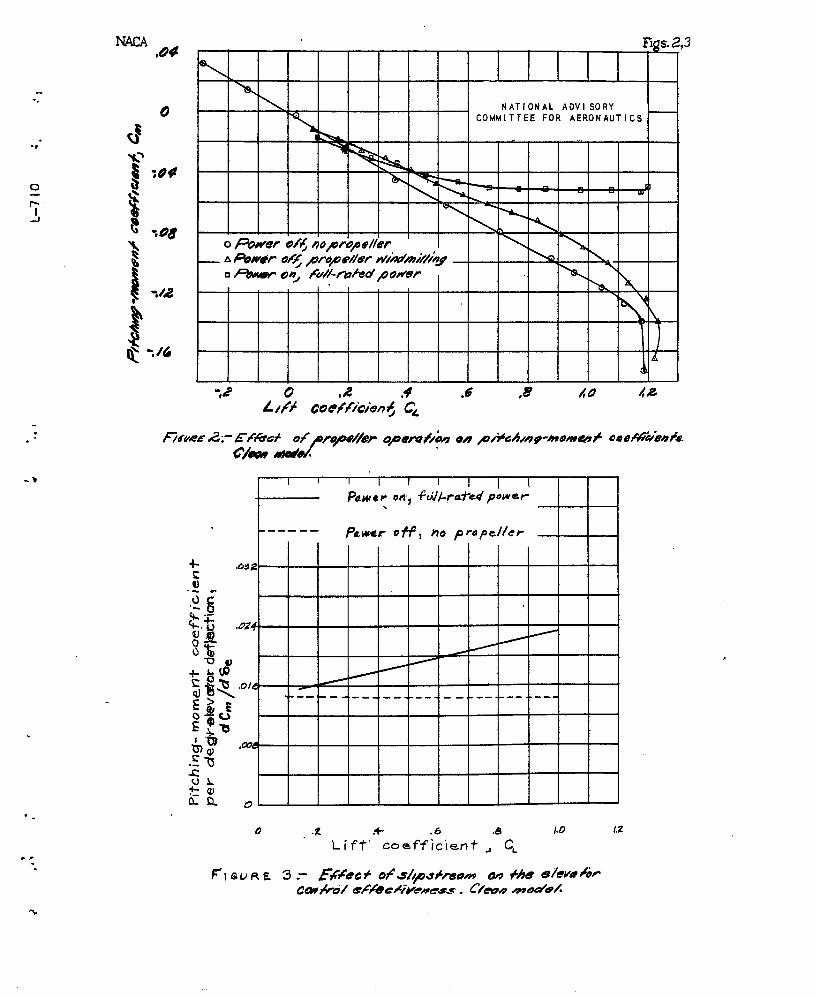
1, The effect of prope?.te~ operation wa~ destr.bil.i:j-ing whether or not pcwer was ayplied (figs. Sl(a)”and S(b)),The windmillifig propeller decreased. the slope of the CurVeof pitching none’nt a, ainst
flift shout 25 percent bol’ow the
propellsrureaoved VZ. ued A-pplicatior. of power decreasedthe sloye of this curve still further, hut” the decreasewas apparc’nt ly not a di~ect furction of the power applied.
,
.%.
-.
. .-1.
. .
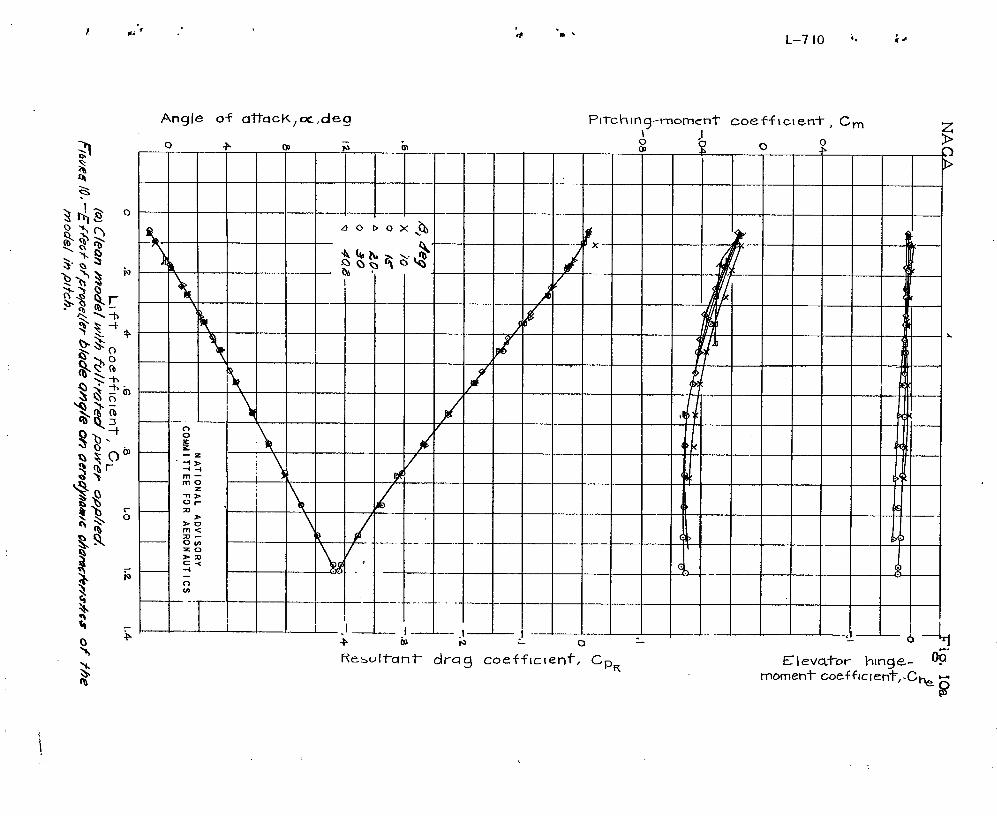
2, The’application of power iucreased tho slope oftho lift curve anti th~ increase was approxim~iely pro-portional to the amount of po’,.mr(figs. 9(zL) and ‘3(3)).The maximum lift coefficient also increased with pov?er-(fig. 9(a))*
3. An incrc?.so in ~royeller-bla.de angle slightly de-creased the slope of the pitching-monent curve for. the
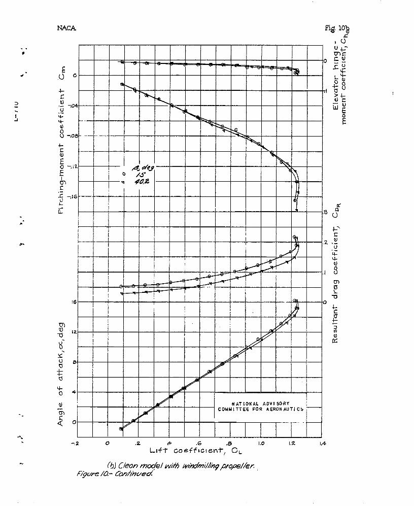
fu.il.-power Condition (fig, 1~(.~-))but hmd no apprec~~,~ie “effect on the slope for the propeller windmillir.g condi-=tion (fig, 10(3)).
4. The stabilizer effectiveness was constant tkcrough-out the lift rc.nge for the propeller-windm.illing contrition,just as it usnally is for the ~ower-orff condition. Thiseffect is shown by the ‘pitching- moment cur~’.esof figure11(o), whicl?.are approxiae.tely linear and parallel. The “st,nbilizer effectiveness ~p-creased with increasing tk.rustcoefficient for pOiVer-On opeu~,tion. This effect is shownby the di-rerging pitching-moment c.ur~~es of figure Ii(b)
where t’he slope of tb-e ci~~vcs decreases with decro.asir.g
positive values of Stal)ilizer angle. (The thrust cooffi-tier.t ,in.creases with-l lift coefficient,)
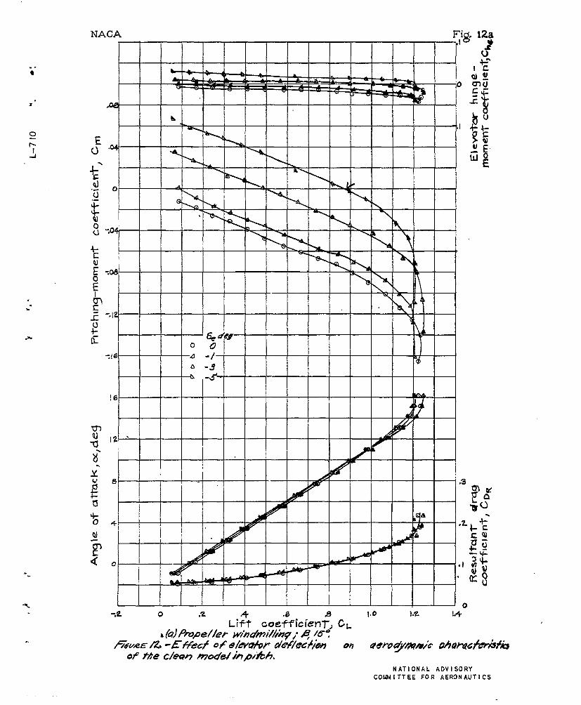
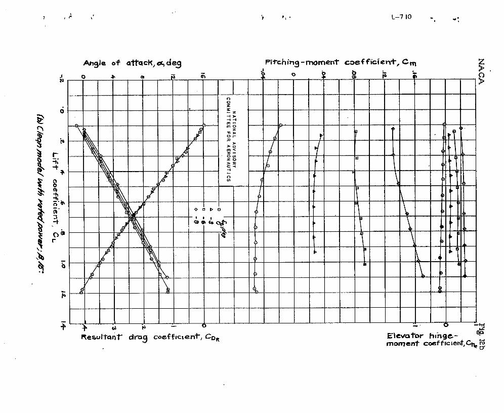
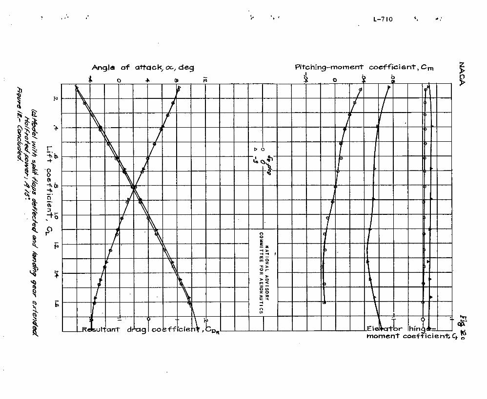
5. The elevator effecti=~eness s.nd the slo~e gf thepitching-moment curves ‘for the ~’ariov.s deflections (fig.12) :?.ndpower conditions were ;zffectcd ih. thd saroe waytb-at tho ste.biliztir effectiveness and sl.opc WC1*C ~fi’ccted.
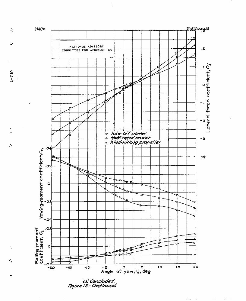
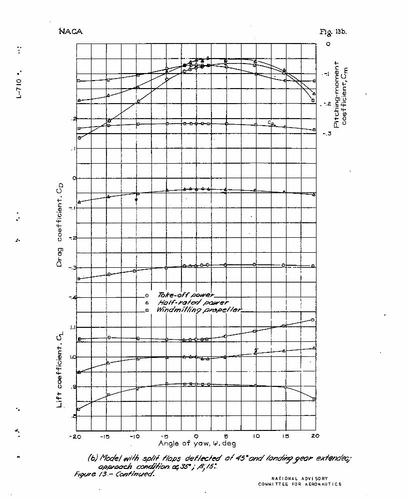
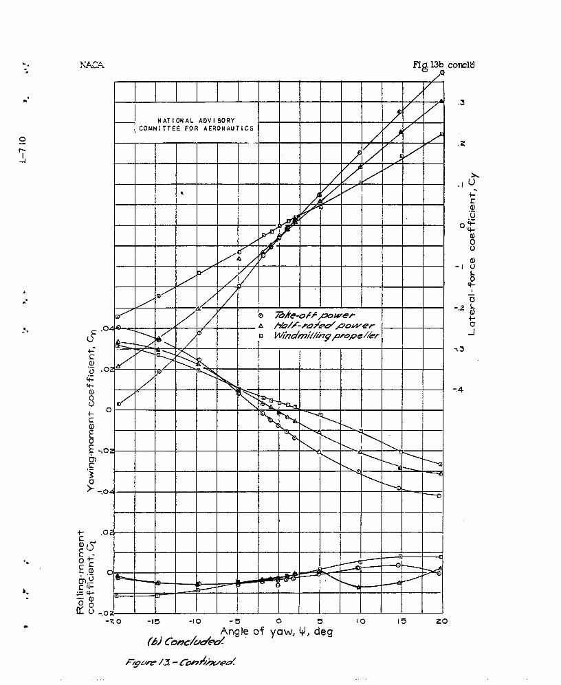
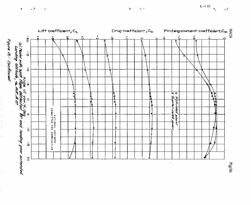
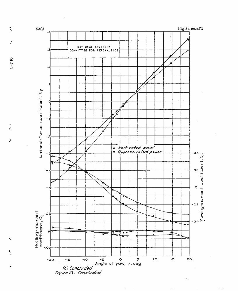
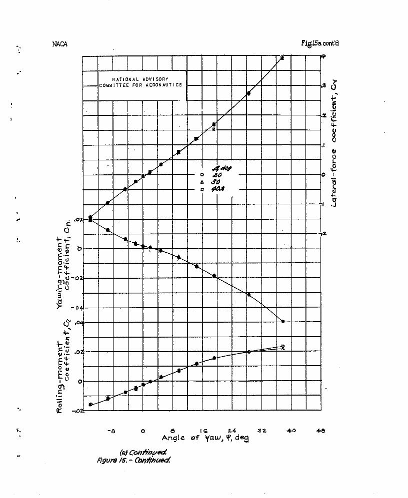
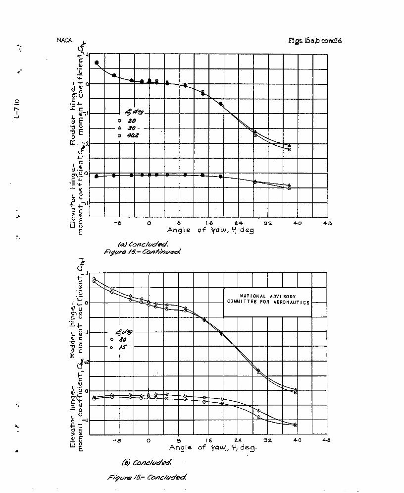
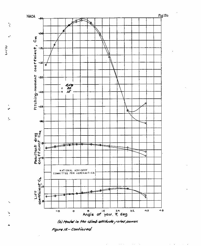
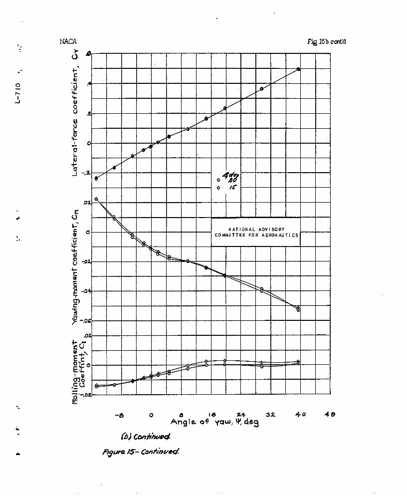
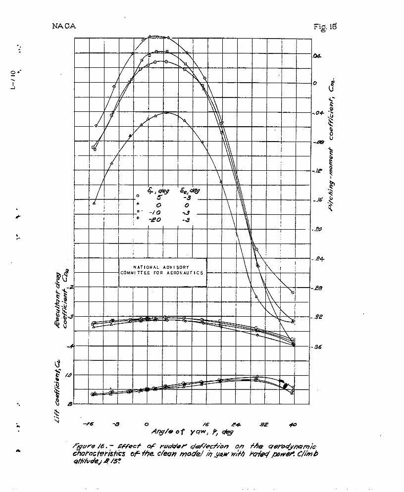
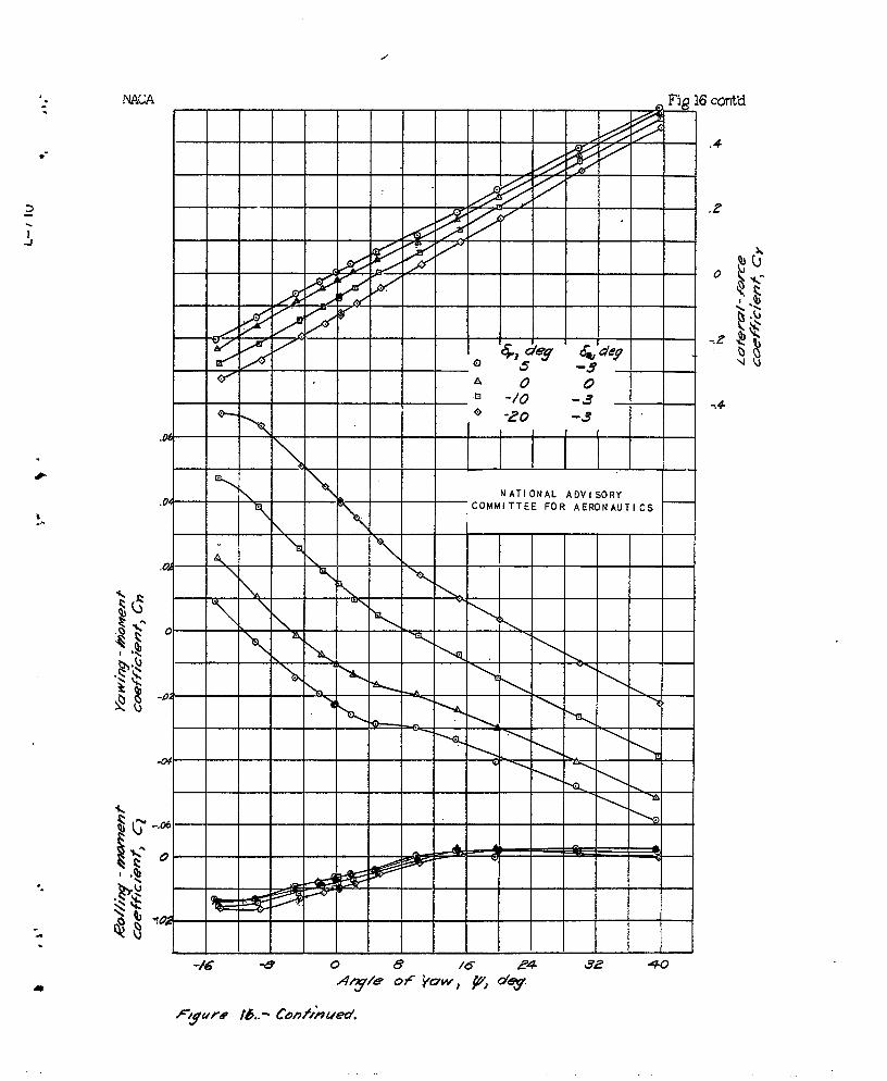
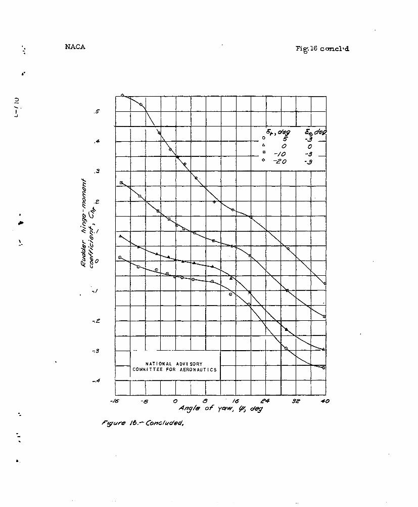
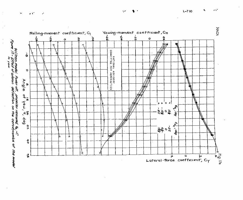
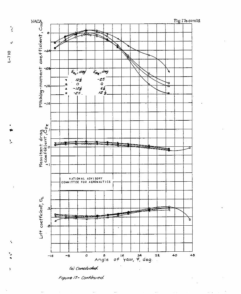
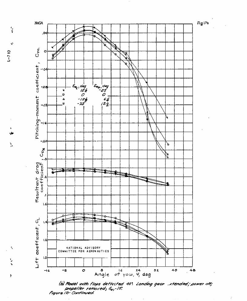
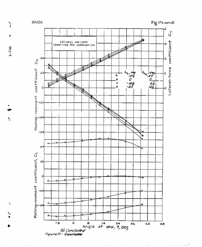
Characteristics in yaw.- ‘lke resul$s of the yaw tests
of t~ie model are presented in f~g-ares 13 to 1’7. The fol-
lowing points are worthy of note:
.
DISCUS S1fllT
. .
. ..
,.
. ..
.:
-. -.
-%
-e
.
~he axial velocity of the slipstream Increases the
elevatcr and, stabilizer effectiveness, provided that the islipstream passes over the tail surface. The change ofvelocity at the tail with lift coefficient is destabilizin,qif the.tail lift is negative (down) and stabilizing if thetail lift is positive (up). !l!he:flestabilizj.nqdownwash rat the tail is increased by the.axial component of theinclined slipstream. It may be noted th?,tfor cases where’
!dc>;,..the tail surfaces have a dest~~,loilizingeffect
\Ti )—.*- an increase in tail area will increase the inst’ab’ility,
..
..
-..
. .
.,
.
-.. .
-.
.“ .-
-.
The incuec.se in ilynr.rnj.cpressure over the fLISelZge.5.ndsurfr.ces cotitri.butes to the clzanges”in pitching momentto ytiw. The ~-ecre,~~e in the effective dik.edral. . causedpm’rir is 12elicveii to le partly due to the fact that, v?z~enthe airplane is y<a,wed$the slipstream is deflecteLi o~’o~’ the
trxlling-t-ing panel and incr,:ases the dyfiamifi pressure and3
conseguently$ the iift of the trailing wing. This i.n-
croas{d trailing -wing litt (and decrmsed leading-wing
lift) r,esults in a rolling moment that increases with aB--
glc of y?.w but is of oppos~.tc sign to the, normal (dcsir-
o.’bllc)dihedr~.1 effects. This difference in the dynamicpressure upon the two sides of the wing panel mlso con-tributes to the yawing moment due to yaw. The positio~.of the center of pr~ssi~r~ of th.o vertical tail with rospcctto the X axis determines the influence of tho incrccso”d
tail effcctivoncss upon the dihcd~al effect.
Although it hns not beta definitely cstnblishcd, it isthought that tlie Affect of’wing- fuselagc intorfertiacc upontho rollir+g anti yawing 130meiltSLue to yaw (rofcrcncc 15)m,ny bc in-creased by the incroa~ed dyna@c prcs~urc of thC
slipstream-. Thus, tlzc <adverse effects of ir.terferon60 onthe effective dihedral of low-wing i~OllOpl.a.r.eSwould Ye ig-creased an& the” favor~vble effects Of the interference forhigh-wiilg l:onoplanes would al-so he increased. Thb .sn.mel?eaSOni.ilg indicates ,that the favorable interference uPonweatihe’rcock .staliliiy of low-wing monoplanes WOUld, be i~--creased, and %b.e unfc.vorr.”ole interference of high-wing
monoplanes wo-uld also %e increased. Because the sidewnsh
angles at the taii are,dotermincd as a v.octor..ndditi”on ofthe various COmPOaeIItS of air flow a~e to the :=ne~ the
,,
fusola.go, r.nd the slipstream, the ~?.xi~l,~velocity h~~sarather lrbrgodirect influcnco upon the sidcwash angles ofthe tail.
U!hcvclocitios noi-malto the axis contribute tovr+rcltho sidewo.sh mglcs of the air flow passing over the Wingl
the fusol.at;e, and tho tails Ono of the effects of thesidowash at the wirigs is to resist the undcsirablo dis-,placcmcnt of the slipstrcam$ which dccrcc.ses the Offcctivcdihcdralg The sidowash nt the ‘fusel~.gc nr-d nt the tr.ilsurfr.cos chaagos the angle of attack of the fusolagc andthe tail surfaces ,nnd thus dccrcasos the SIOpC Of tkOyawin~-momont curve ●
~bc rotation,ll Velocities in thc slipstream r.ltcr tho
‘tack.distribution of that portion of the wing~anglc-of-Cn.uimmcrsod in the slipstream and therely produce a rolling
.
moment ● The rotational velocities over the wing andthe.,f~selage$ together with the increased dynamic pressure inthe sli-pstream, produce rather Fowerful yaving ~oments.ghe ~o+t~er-on y<a~~ing-m.omentcurve-- -obtained without t~ilsurfaces is usually r,arkedly unst,a-ole~ 5.s unsyr.meiri cclabout ze::o yaw, and b-as a larger negati.v”cyawing moi~ent aizero yaws The yawfilg moment at zero yaw is usuzlly iP.-crcased negati~ely ly the taj.1 surfaces tor full-power op-eration even though tho vertical tail is offsot 1° or 2°,~]~e’se rotatfop-al ~elocftfes .~~ccount in a large rlea~~re f9r
t~le effects of ckemges in prc~el”ler--blade angles.
.
,.
.
---.
.
...
?
“..-
-.-
.
-.
.“.
-.
.APH?JTI)IX
COX3’FICIENTA3TD SYMBOLS
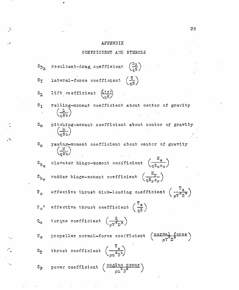
~~result ant-tirag co,efff.cient ()
F5 /
lateral-force coefficient (.x.\qs )
rolling-reorient coefficient, a%out center of gravity(~
(@ )
pitci.ing-morient coefficient a$o~t center of gravity,( ,“,)
\&) .,
HVrudder hinge-rionent coefficient (.---=.-)
\qsrcr)
(,;,’)e’effective thrust disk-loading coeffi.eie.nt
T
()effectfve tklrust coefficlefit Q
qs
torque coefficient(F3D )3
yropeller normal-force coefficient(~ormal force
p’{-D2 )~
() e~~rust c~effic~e~t ——pn2D-1
~oirez’(
cnginocoefficient
po?rer
Pn.3D5 — )

“.
%,
lateral f’o:r’c!e~ positive when directed to right
yawing rncmeritabont Z axis, positive when it tendsto retard right whag
Glc;vatorhinge w.omnt .s pOSi’bl V”e dow~l,var~
“Vvi.nqar~a (9.44 sq ft)
wean aerodynanil.cchord (L.36 ft)
clt;vatar area back of hin~~ (0.621 sq ft)
rudder area back of hin:c (0.471.sq ft)
root mean sq~am elevator chord (0,2C4 ft)
mot mean squm’e rmddsr chcrd (C.403 ft)
eff’octi.vcthrust, lb
ELimpcecl, ft/mc
prope-llcr Mmeter (2.0 ft)
.
-.
.
-..
. .
. 37’ .
.
-.
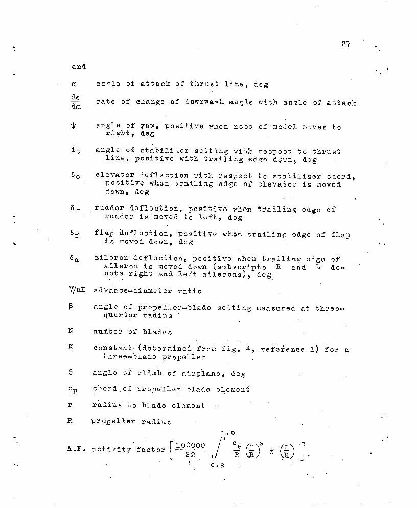
anrl.e of attack of thrust line, deg
rate of change of downwash an~lo with an.?le of attack
elevator deflection with respect tO sta’oilizer Cho:’d$positive when traj.li:l~ edge of elevator is aoveddown, Lcg
rudder iicflcction, ~ositivc when ‘trailiag edge ofrudder is moved t: left, dog
flap d.cflcciiion, nositive when. trailing edge of flapis rcovcd down, “dog “
aileron dcfloction 9 po~fti~’e ~’rh~nt~ail-ing edge caileron is moved down (subscripts R and L dAnote right and left aAlerons)9 deg,,
If.e-
advan.ce~dtarneter ratio
angle of propeller-%1 ade setting measure~d at threc-quarter raiii-us
nu..aiberof blades. ,,
cons~tant. (determined fro~~ fig. 4, refe$en~e 1) for athree--olade Ftopeller
radius to blade eleme,nt ‘
propeller radius
1.0
““ [Q&j’?(-)y$)] ~activity factor
,’0.2 .
.
..
.. .
.’
. 38
. .. 3,
G-b
6.
-.8,
.
.“
● ✍
✞
.#-
.
,W
.
ii”OA
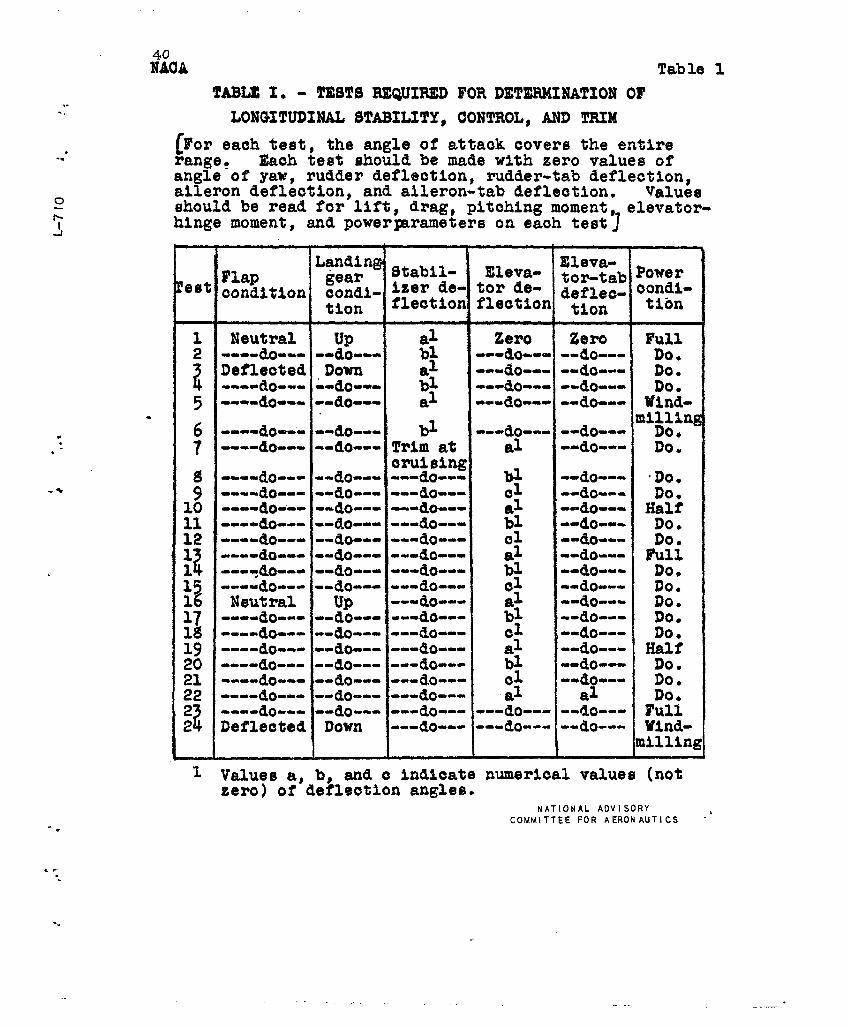
TABLE 1. - TESTS REQUIRED,-.
LONGITUDINAL STABILITY,
Table 1
FOR DETERMINATION OF
CONTROL, AND TRIM
. [$’or each test, the angle of attack covers the entire-. range ~ Each test should be made with zero values of
angle of yaw, rudder deflection, rudder-tab deflection,aileron deflection, and aileron-tab deflection. Values
o should be read for lift, drag, pitching moment, elevator-+~ hinge moment, and powerpuvuneters on each testj
.
*..-
-.
.-“.
1
L-ding ~tabilFlap gear
‘est con~~~ion condi-tion
1 Neutral up al Zero Zero Full2 ----aO--- --do--- 1)1
2
---do--- --do--- Do.Deflected Down al ---do--- --do---(
----do::: ::*::: bl
Do.----do ‘---do--- --do--- Do.
5 al ---do=-- --do--- l$Mi-
6 ----do--- --do---nzi$::ng
bl ---do--- --do---? ----do--- --do--- Trim at al --do--- Do.
CWuislng$ ----do--- --do--- ---do--- W --do--- ‘Do.9 ----do--- --do--- ---a.o--- ~1 --do--- Do.
10 ----do--- --do--- ---do--- al --do--- Half----do--- --do--- ---do--w b~
::::~--” Do.
‘----do-----do--- ---do--- U1 -0. Do.12
----do--- --do--- ---do--- al --do--- Full---+lo--- --do--- ---do--- bl --do--- Do.
i?
----do--- --do--- ---do--- cl --do--- Do ●
Neutral up ---so--- al --do--- Do.;7 ----do--- --do--- ---do--- bl --do--- Do.M ----&o--- --do--- ---do--- cl --do--- Do.19 ----ilo-----do--- ---do--- al --do--- Half20 ---.dO-----do--- ---do--- bk --do--- Do.
----do--- --do--- ---do---‘ QI --do--- Do.% ----do--- --do--- ---do--- al
?
al Do.----do--- --do--- ---do--- ---do--- -“d!o--- Full
: Deflected Down ---do--- ---do--- --do=--- Wlnd-milling
COMMITTEE FOR AERONAUTICS “’
.=
.
EAOA Table 41
..-.
.-*
>
..“
-%
“LADu& &A
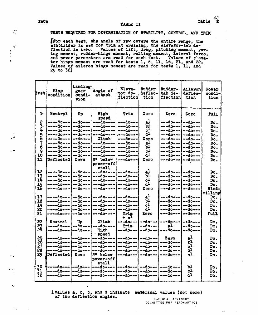
TESTS REQUIRED FOR DETERMINATION OF STABILITY,CONTROL,AND TRIM
[For eaeh test,the angle of yaw oovers the entire range,thestabilizer is set for trimat crui8ing,the elevator-tabde-flectionis zero. Valuesof lift,drag,pitching’moment,yav-ing moment,rudder-hingemoment,rollingmoment,lateralforoe,and powerparameter are read for eaoh te8t. Valueeof eleva-tor hingemomentare read for tests1, 6, 11, 16, 21, and 22.Valuesof aUeron hingemomentare read for teste1, 11, and25 tO 32]
Landing-Flap Eleva- Rudder Rudder- Aileron Power
~a:y;f tor de-‘et condition %%i- deflee-tab de- defleo- oondi.tion flection tion fleotion tlon tion
1 Neutral up High Trim Zero Zero Zero Full
2speed
----do-----do------do-------do---
i“
al ---do-----do--- Do.----do-----do------do-------do--- bl
cl ---do-----do--- Do.----do-----do------do-------do--- ---do-----do---
~Do.
----do-----do------do-------do-------do-----do---
dl ---do-----do---dlimb
Do●
---do--- Zero ---do-----do--- DO.
~ ----do-.. --do--- ---do---- ---do--- al ---do-----do--- DO.----do--- --do--- ---do---- ---do--- bl ---do--- --do--- Do.
9 ----do-----do------do-------do--- 01 ---do----.do--- Uo●
LO ----do--- [email protected][email protected] d~ ---do-----do--- Do.11 Defleoted Down 2* below ---do--- Zero ---do---ood~--- Do.
power-offt3tall
12 ----do-----do------do-------do--- al ---do-----da--- Do.1i
----do-----do------do-------do--- bl ---do-----do--- Do.1 ----do-----do-----=do-------do--- ~1 ---do-----do--- Do.15 ----do-----do------do-------do--- dl ---do-----do--- Do,16 ----do--- --do--- ---do---- ---do--- Zero ---do--- --do--- wind-
mil:$g17 ----do-----do------do-------do--- al ---do--- --do--- .M ----do-----do=-----do-------do--- bl ---do-----do---lm9----do-----do--- ---do-------aO--- ~z ---do-----do--- K:~o ----do-----do------do-------do--- d~ ---do-----do---21 ----do-----do------do---- Trl
!!Zero ---do-----do--- F&
+a22 Neutral up Climb ---do--- --do--- ---do--- --do--- Do.~?
----do--- --do--- ---do---- Trim --do--- al --do--- Do.~ ----do--- --do--- Hi.@ ---do--- --do--- ---do--- --do--- Do.
~5>speed
----do-----do------do-------do-----do--- Zero al Do.26 ----do-----do------do-------do-----do------do--- :: Do.~7 ----do-----do------do-------do-----do------do--- Do.~g --m-do--”.+@-- __-do______do__- __do___w--do-- d~ Do.?9 Defleoted Down 20 below ---do--- --do--- _--do--- al Do.
powm-:ff
JO ----do-----do------do-------do----.~o-.--~-do--- bl Do.31 ----do-----do--- ---do---- ---do--- --do------do---~ c1 Do●
52 ----do-- --do------do-------do----do------do-- d~ Do.
.
lValues a, b, c, and d Lndloate wnmrioal valuea (notzere)of the deflection angle$.
NATiONAL ADVISORYCOMMITTEE FOR AERONAUTICS
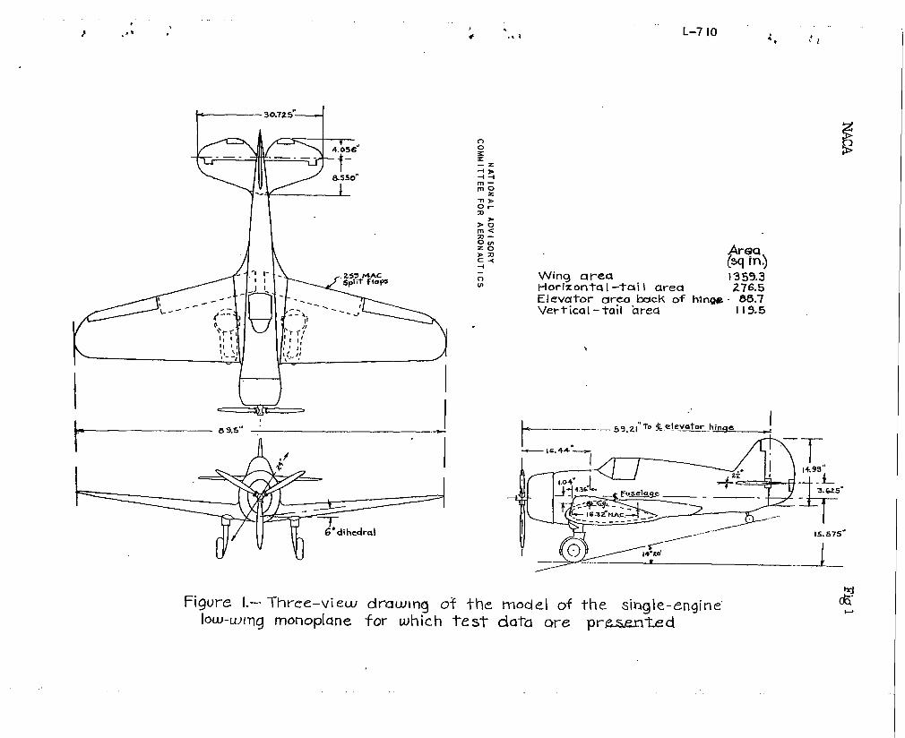
t-----’”’’’”+
\
Figure I.– Three–view dmwln~ of
Clo2-z
+>++
m—m:
L-7 10
c-l Wing area 1359.3m Horizontq I -taiI area 276.!j
El evutor urea back of hinge 86,7Vertical -tall hrecl I 19.5
.
-1
&.—._... –.9,.I”T04 .!e.vk..-hmx. I:.44.”’-. /d-x” l-
-P-I--L-3=- I -_.r -UT
! %G2+-’-”----’ I
15.575”
l’(f=:~..k.:.=h 1-- ------------- I
~–v ._J-----
-l-he rrmdel of the single-engine” J?loww)l~g monoplane for wh~ch te ST data m-e pr.~-kd
,04
..-.
.-,
0
..
.-
-r Pawa F w, # dbrated power.
--—. — l%wer off, no prapeller iH4-S0---
.
. .
.052
.02’4,
.016. -- --- ---- ,___ ---- __, ---- ---- ---
,ma.
0
0
FIGURE 3
Figs.4,s
. .
...
0r-1-1
.00/6
.Gwz
0.(ztw
.000+
NATIONAL ADVISORYCOMMITTEE FOR AERONAUTICS
o
72’ 0 .2 .4 .6 .8 [0 /2L /// coeff~clen< Ct
Fiiure 4?- Effect ofprop8//er operu~iotion /he effecfiyed/h6dru/. Clean mode!..
..-
.*
,0+
,02
o—
-co~
0 Power off , no propellerA Power off , p~opeller windtnilling
A v Power on . h a I f -rated power0 Power on , ta K=- off’ power
\
-.
~..
-.
-24 -16 -e o 8 16 2+
Angle of yaw, y,deq
FIGURE 5 r Effect of propeller operation on gawing -mom en+ coefficients . ‘5f,0” j CC,9.2” .
7VAC
.-
t$
-/5
-/6
-5
0
-/d
-5
0
5
--
. ..
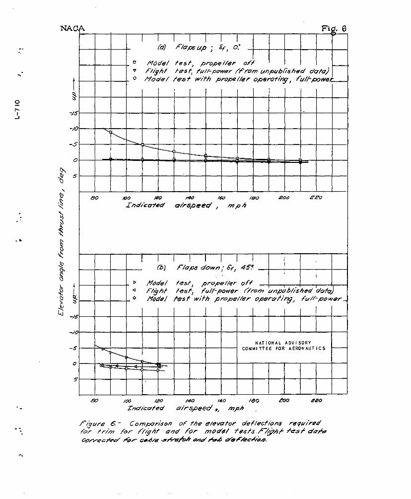
L Fig.6I I(2?)Flu/mup ; &f, 0.”
❑ Model fes t, prope //er offv F//ghi fes < fu//-power {from unpublkhed dufu)o Mode/ fes * witih prope //er operofi~, fu/..-powet -
h
+ ~
80 MO /m * /60 /6’0 200 220 I
I I I I
(%] Flupo down; 8{, 45?,
D Model test, pro>e//er off)
\ , 14 F/.hf tesf, full-power ffroh unpublished “dufu)o /YQd81 fes f wikh PZpe//@~ OperU/i~, /U//-PO wffr _
NATIONAL ADVISORYCOMMITTEE FOR AERONAUTICS
-.
. .“.
.●
✎✍
-.
. ...
-.
N.A CA F~Q. 7conc-1~
. .-.
*.-
35
.8
.7
.
.03
.-
. .+.
{n
A
.— .- —— - .- —- .-— .-— —
-- --- --- --- --- --- ---- ----- ---- --- ---- ----- .
b’ /’‘y \ .
r\ “%& :&\
A \\ ‘\\- \
\\ ‘..
\ \ ~
\-.- 1 .
x =.-‘. ---\ . < \‘.
. ., t \
M2delprope/\ero%%o!eg ‘N\
——? /5 -.,- .+
b—-----—-——--—‘+kkiComhf - speed uj~pkz.e pqtwl.er
.d/
NATIONAL ADVISORY / ‘COMMITTEE FOR AE~ONAUTICS
.
/’ -.
/“
-,
/
o 2 .4 .8 10 62 /4
Llff coeitclenf ~ C..
Figure? - co/7c/Mded.
-.
. .
.
4-
0
.6-1-vl3
i+ .+
~.-+ual .Z
$
0.
-.
-.
t ~~ k!a,b
. Fbwer . (hp) (rPm)
I --------- T,a Ke-off .. {200 18@Rated Ioso 1700
—— H a If-rated .525 I 700
d,/0/
0,/”
,/’/ / ‘
/
.+ ‘ / ‘
p “/ “
// “
c1 .Z .4 b .8 1.0 ).2 l.+ t.kLift coeff’lcient, ~
+ l+{.———.I I I I
.
NACA FiosdC, d
0
. .●
✎
✍✎

NACA
#. .
-...
4800NATIONAL ADVI SORY
COMMITTEE FOR AERONAUTICS
—
0
4400 !II
/
~—.-
4000
I
i? . .,— —.
g-
;3600 . -!
& i,2l-lg
k3200 —
~,/”,.,
I
42800- /
//
2400
0 2 4 6 .10Tunnel angle of attack, a, deg
(e) Final tunnel-operating chart for the clean model: full-ratedpower; !3,15°.
IY.guzze8.- Concluded.
‘1.
NACA Fi~. 9a
.-.
0
7’-i
....
+cm
-r ! 1 1 1E
--9rl A ,,
1
r /x ,, I. I , I c.——,:
/: \ I 1 I! V,l ,, ; 1,3 t
, , , $ I f+
~ I I I I, -+4+- ,W h
0Q)
,~ 1
%I
INATIONAL AOVISORY
COMMITTEE FOR AERONAUTICS, ----1t I
1
●
*“
.9.
. .
. .m
.
-c
iI
.2 4 ,6 1$4 1.6Lift c~ef-fici~~t, C~2
(b~ F/ops defiected, /o#d/hq geo~ ex~endeu!
Angle of altacK, cc, deg Pl_t_chlng-rnoment Coefficient , Cmz
Resultant drag Coefflclent,CPK El evatcx- hinge- @
moment coefficien+,.-Ck w
8
. .#
..
●
.>..
E
“o
:0
s+ w- ,1
$$- 704 -L1.-
++ ... .- -
al
$ -,08 - 1 i----- . ..... —.I
+s ..... I I
;-.17- 1/
:~, dcg ~
1~-: $2
x
i“I
,-L:,-n- S3
It II
1
I
++- -l---— — -
lv~ T I;-- I/ ~I II!! I tII I I1i!;
[6 1I
I
II i
TIi;
Ii
-a 12 !!1-.. —I
~ ~~
/i
-.
K’ 1“
:8 I$ ,!
+0+
A
NATIONAL ADVISORYCOMMITTEE FOR AERONAUTICS -
0 !# -.. ..— .
a y
->2 0 #2 fl- .6 .6 I.0 142 1,4
I_lftcoefflclent, CL
‘igd10~c
t’EQJ,_u,_
u-
(b) Ckon mo@el Mh wl.miMhgprope//e~F&xre /0- Cm/%ueu!
4. 8.
Angle of altacK,oc, deg PiTching-mloment coeff-icient, Cm
hix=. ResulTanT drug Elevat’or hinge- 6<2. coefficient, CD= m~ment coefficient, C -
% %
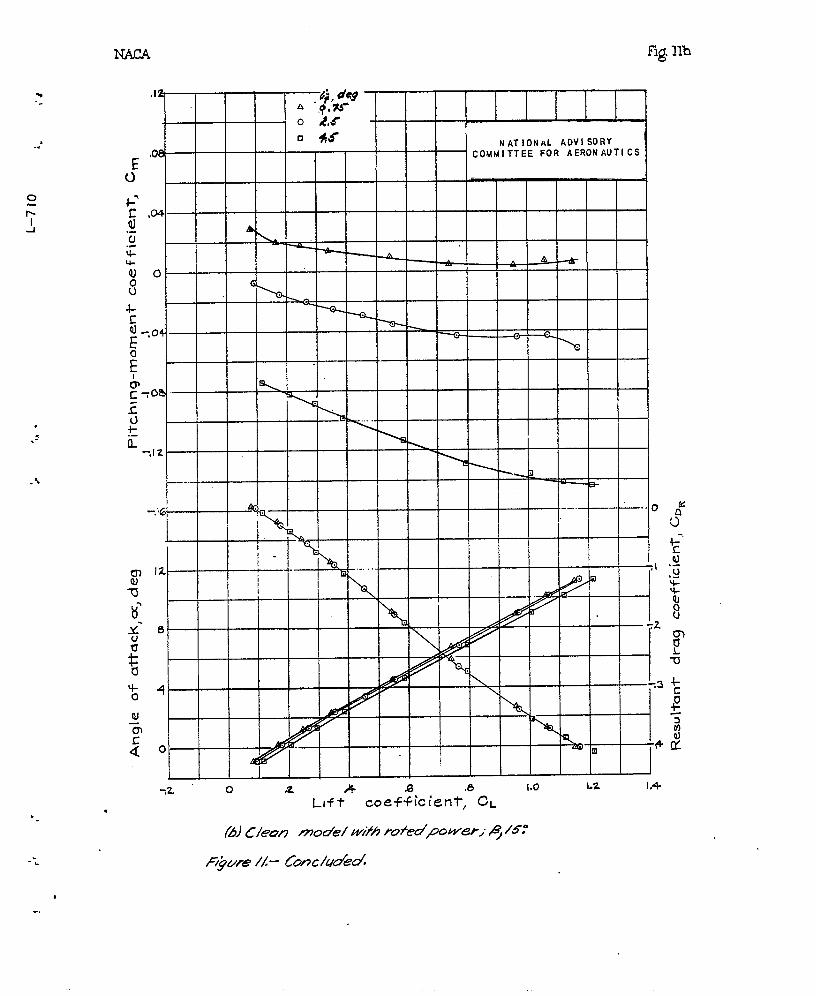
fig. m
.-.
●
o +5 NATIONAL AOVISORY,08 COMMITTEE FOR AERONAUTICS ,
,04
0
g
;04
E
& d -c yaa
zL)
E-,IZ
r-----
-.}6i .-—.–...0#t ot s!-1~ 12
{
I1
f I$ 6 7Z
[ -o
%4 -
QI—6
~o
-2 o a .+ ,6 .5 r.o 1.2 I.+
Lift Coefficient, CL
(2J C/eon model W~fA ru+ed~ower,” ~ Is:
Figure /L- Cmc/uded.
.-*
*r
;1
i
II h
.
llr’=L>
h
Illlllx.x+l
1111111%11
c-ii‘w- --4I
,<
I Id ~1 I I.- A , , I I
I I I I\Al : I
ii I I I k M I‘s I
I 11111
I I 11111..
r. L I I Iz -.IZI I I I I 1 1 I I 1“ I 71 I I
I 1 11111: I-I-H-+4!! ! t t I I I I I IM I 4.D.
‘ill loallllll IIltll
“’t_tt_H :! iI I I I I I I I
IEI I
m
-, I I I I I I 1! I I lx I I Ij
I I I I I I I Ii’ I I I
1 I I I28
1I l-l! t I--36I--H-
i= I Iu I I 1 1 I 1
I1 1A
4- i I [1I I [n I d
Q1 I I I II ii
-p I&I m i 1 I
IL I I‘!@fc-
“-
-%
.,
? ,P.
, ‘7 @t‘ L-7 IO .s
*:
.1N
.
. ‘.,, ,’ ‘-- ‘$ 1
Angle of atktck, cc, deg Pitching-moment coefficient, CmE
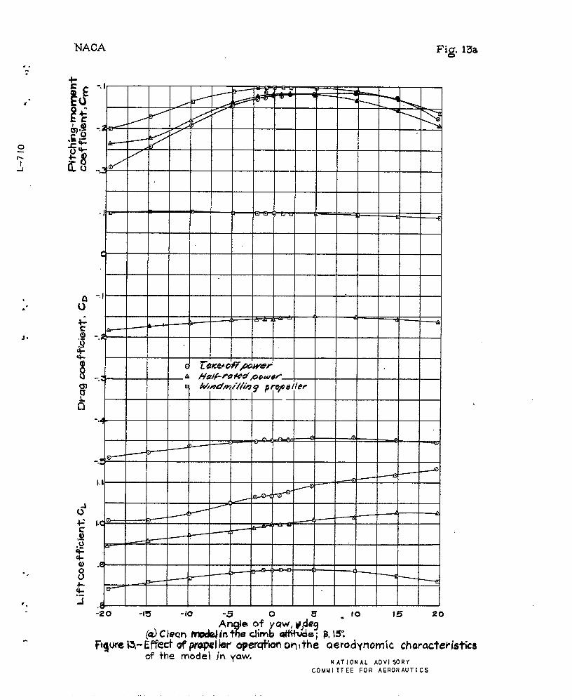
Fig 13a
..“
J.
-.
-z o -15 -10 - ro ?5 20i5 Ie of ~uw, ~$e~%!@ Clecm nwcJeJh e c!imb dK+wJe; B,S.
Fqure S- Effk!d of propel kw opefqfbn on lthe aerodynamic chamcteo+ +he mociei in yaw.
NATIONAL ADVISORYCOMMITTEE FOR AERONAUTICS
.,*
.*.
“.
.*.
NACA
._l ‘NATIONAL ADVISORYCOMMITTEE FOR AERONAUTICS
/
o Take- df pwer
8
K@,-
1 l\ I \ . II I I i i i
--1-
*O2
i
I I
(U.-.4” i Pi--rm-q (--I
“%’H
,2
‘+
. ..
●
☛
o
..“
“.
.4,“ -20 -15 -10 10 Is 20
X:gle of ~aw, W, ?eg
o
+-
-.3
COMMITTEE FOR AEWINAUTICS
*.-.
-“
.1,
“’
b..
IW2A Fig. 13: c
/,/
/4
— NATIONAL ADVISORY / ‘., COMMITTEE FOR AERONAUTICS / /
1
/ /
/
&
/
D’/
o Z6-o/Ppwe~ ,
.04 a.
J e’d D W7dmwfffgpopexer ,
...ca).-~ .02 ,0
C+g
L)
toc
i!
1?,-3
$
‘g .OzIDJE0:’Ea~ ~~ Q
—ali? s ..~~
.3
.Z
-.3
-.4
L-”! Ior ,,“ ●’ ,,. .. “ 4. ,,*J
&if* coefficien~, CL C)rq Coef f iciemt ~ G~ Pitching-moment coef ficien~Cm ~
7 r 7- 7
\
\~
\
4
<Q
00
x
-z-ID--l-i
-n>or
>=(n<
Zo
*Wc<
0I
4 —
-.-. NAC4
.’
0
‘j
3-
.*.
‘.
F@13cconcl’d.4
4
NAT ION4L ADVISORY.3
/
t-
COMMITTEE FOR AERONAUTICS
. .- # /
.Z/
P
I/
4
0
-.1/
-t “
///t
.-. ------
I /-.
1
-.
-.G
/
-.5c
“-,-
A kQ ~ — v
“,0.2
-20 -Is -10 0 5 10 Is Zo
A~~e of yaw, W,deg
(C) ConcludedF/gure /3 - [one/uded
*. NAC4.
●✎
.#
.?.
“.
b.
.
.
F@ 14
.0Io
0
.--—
YOl ----
I
0
1— — ~0~ ~ ~ ~
.-.0 02
A
I
1
–t ~—:
i.004 -,..—
I I‘~ ,1I
,002 I
k I
o
NATIONAL ADVISORYC01.4MlTTEE FOR AERONAUTICS
t----- .
I

-. NACA.Fig15a
4&9020
clNATIONAL ADVISORY
COMMITTEE FOR AERONAUTICS
.. .
“.
4-.--1
-8 0 az 40 48An~le oi=pw,$~deg
r.
-..
.“
I
1
t
.
d
m. .
“.
s.
w
NAcA,#
Fjgs15a,bconcl’d●✎✎
.. .
A
@ co/7c/udd
F/ywe /5- ConA%vecd;L,,‘w.1$0.-0.- NATIONAL ADVI SORY
COMMITTEE FOR AERONAUTICS —1:09.)000~u
“i +
al~-50 0 do
7 ,EM
Cfz.=
g
LCJ-.1
j?+UC
1? ‘8 o 32 40~o
48
E A~gle of’ ‘~Q&., {4deg.
(-A)Conch%d,
F/gum /5- co/7c/uof5d
w-...
.. .
“.
15b
NACA fig15bCCRt’d‘.-.
●✍ s I II II
I I I I IU I 11 IX-7L.!I)
I I II w I
I I/l II
i I I$ 0 I l\\ I I I I.-U.— I I Iu I I Id$70 I I I I I It I I I
111.1NATIONAL ADVISORY
WI 1
COMMITTEE FDR AERONAUTICS
l—
1111
111111!1 l=\
-,
iiI
Eg -.04f%’ I I I
Ii?
-8 0 32 +0 48Ggle of’6yaw, ‘~’eg
(h) @77%&m#
F)gute 1S- Com%ued
‘...
..
-*.
/
‘...
●✎
.
..
..
1
cent’d
.4
.Z
-.4
J+gum /6,.- COAV%W?CY.
,. NACA-.
*’
Fig.16concl~d
.5
.4
.3
-./
-.Z
.3
-.4-1 NATIONAL ADVI SORY 1
COMMITTEE FOR AERONAUTICS Y
1I I I I I I
I 1 1 , 1I
1t
-/6 -8 0 C9 16 (94 32 40A&-g/e of yaw, & 04?y
Fgure 16.- co~cluded,
L-7 10 % ,,,-
NA(
*
*
?. .
1
1
NATIONAL ADVISORY— COMMITTEE FOR AERONAUTICS
OJ
+’ ,2
u._
?:
2 .0
$,
i
-16 -8 0 24 32 40 40
Ang; e CIf ‘:~clw, V, deg
(b) cbzkwc%d
Flgu~e /7- Com%ueo!
d’d
-.
)
u~ ! 1 I I I I I I I I I I I%:”-11111111
Hlllltllllll{tl II“1
8 I ; COMMITTEE FOR AERONAUTICS
I I I I I I IF I J: “OTrrrrr”” ttnTnTn+
-16 -8 0 16 Z4 32 4-0 4a
An’le of yaw, w, dscj
NACA Fig 17bconc~d
-4
,.