wallaceburg, ontario canada - aar-kel · wallaceburg, ontario canada ... design functions are: -...
TRANSCRIPT
Wallaceburg, Ontario Canada - AarKel Tool and Die Inc. (Main Office, MFG.)
- 110,000 sq. ft. total air conditioned operating space
-156 full-time employees
Head Office/ Die Cast Facility and Design/ CNC / Plastic injection molding Facility
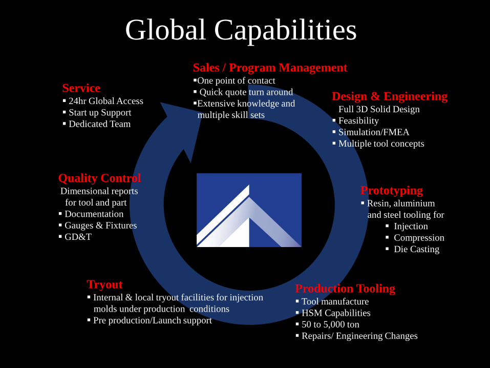
Global Capabilities
Service 24hr Global Access
Start up Support
Dedicated Team
Sales / Program Management One point of contact
Quick quote turn around
Extensive knowledge and
multiple skill sets
Design & Engineering Full 3D Solid Design
Feasibility
Simulation/FMEA
Multiple tool concepts
Prototyping Resin, aluminium
and steel tooling for
Injection
Compression
Die Casting
Production Tooling Tool manufacture
HSM Capabilities
50 to 5,000 ton
Repairs/ Engineering Changes
Tryout Internal & local tryout facilities for injection
molds under production conditions
Pre production/Launch support
Quality Control Dimensional reports
for tool and part
Documentation
Gauges & Fixtures
GD&T

LOCAL CAPABILITIES
Program Management
Die Cast Die Manufacturing
Plastic Injection Tool Manufacturing
Prototype Tool Manufacturing
Product Design
Tool Design
CNC / EDM Machining
Assembly & Inspection
Part Tryouts & Production Runs
Combining the skills and assets of our “Local Presence” and
our “Global Resources” we offer our customers a single point
of contact from which together, we can select from a complete
array of Product Development Services that are best suited
for the scope of your project requirements.
Your “Full Service” Partner

MACHINE CAPABILITIES…
5 axis High speed LARGE CNC machines
EDM Sinker tanks with CNC graphite machines
Gundrills with 5 axis gundrill/boring mill
Welding department adjoined with internal furnace for full process weld requirements
Any Size, Any Shape,
Great Results…

DIE CAST DIES (500 to 4000 ton range)
Ford & GM converter housings
Magnesium Instrument panel dies
Cast aluminum engine blocks
Oil pans
Low pressure & high pressure dies
Nissan ZV5 Consignment tooling
Any Size, Any Shape,
Great Results…

Engineering Manager
Die cast experience – 20 years
Die Cast Specialists
Die cast experience – 29 years
Engine Blocks – 4, 6 & 8 cyl,
including Northstar, transfer cases,
steering houses, transmission cases,
clutch housings, differential carriers,
cross car IP beams (largest
magnesium casting in the world) etc.
Product and tool design expertise
Die Designers
5 Designers - Die cast experience – 20 years
10 years
10 years
10 years
7 years
Program managers
3 Managers - Die cast experience – 28 years
14 years
3 years

6000 sq/ft manufacturing area with its own
dedicated personnel
Has easy access to all AarKel departments
and capabilities.
Fan Blades to Bumper Fascias
Non-Automotive Parts
PROTOTYPE & ALUMINUM PRODUCTION
Rapid prototypes – SLA /SLS
Tooling fease & production phase support
Aluminum prototype tools
Low volume aluminum production w/ full actions
Any Size, Any Shape,
Great Results…

PART FEASIBILITY & MOLDING
ASSESSMENT
Full Draft & Tooling Feasibility Studies Draft analysis and mold ability studies have proven to save valuable time and money. With input from the tool manufacturer early in the program, problem areas for molding as well as molding methods can be introduced for optimum tooling and production requirements. This can have a direct effect on piece price.
Engineering and Design… Design functions are:
- Data management - Feasibility study
- Part comparison - Draft analysis
- Part warp - Moldflow and Manifold
- Product design - Mould design
SUPPORTED CAD SOFTWARE
CATIA V5 UNIGRAPHICS CIMATRON CADKEY/XMD IDEAS/SDRC STEP IGES PARASOLID DXF/DWG
Any Size, Any Shape,
Great Results…

We Offer:
• Full product design and feasibility studies
• Complete internal tool making capabilities from
• 50 to 5000 ton tooling requirements
• 24/7 Program management support
• 24/7 Tooling support from cradle and beyond
program launch on ALL programs
• One stop tool shopping from
DESIGN > PROTOTYPE > PRODUCTION > LAUNCH
• Complete LCC tooling integration (each tool is
torn down and verified that all items are to customer
standards)
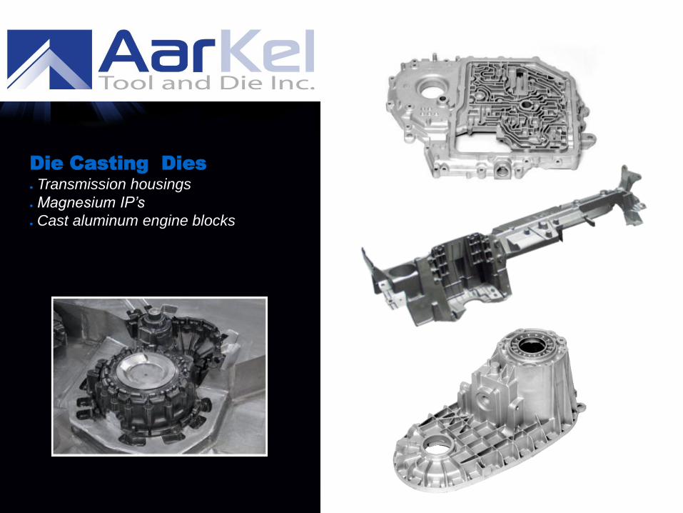
Die Casting Dies Transmission housings
Magnesium IP’s
Cast aluminum engine blocks
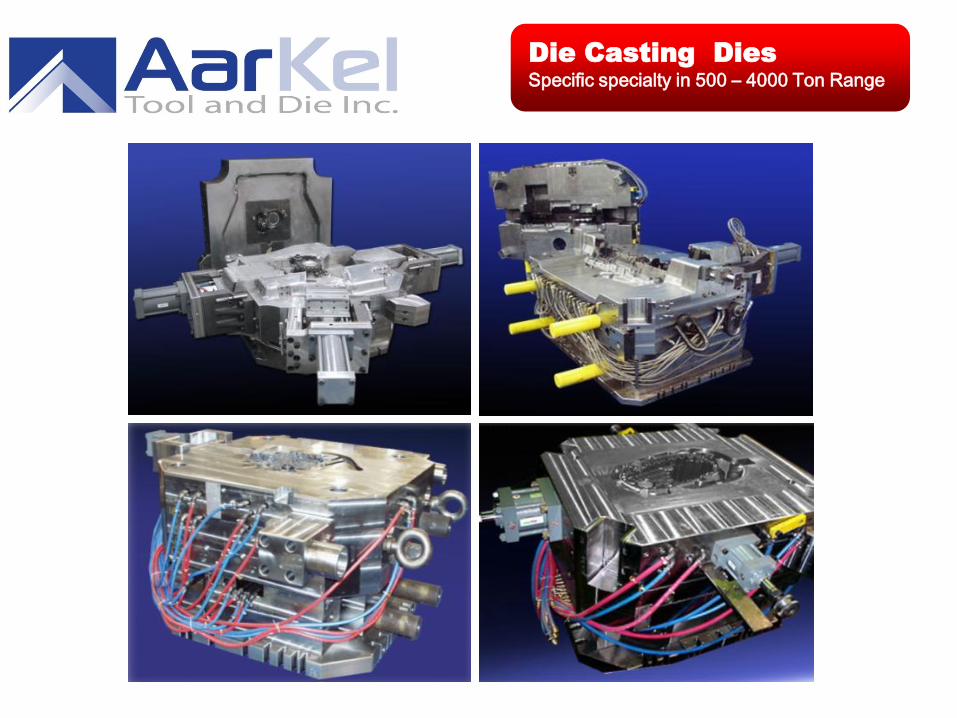
Specific specialty in 500 – 4000 Ton Range
Die Casting Dies

- Replacement inserts 100% certified
- 4T65 Channel Plates & Trans Case Dies
- 4T45-E Trans Case Dies
- 6T75 Six Speed Converter HSG & Trans
Case
- 6T40 Six Speed Converter HSG & Trans
Case
- 6L80-E RWD Transmission Dies
- 6L90-E RWD Transmission Dies
- Northstar Engine Block
- GF6 Case and Convertor (4 veriations)
- Rebuilds & Refurbishments
- Jeep - Half I/P Steering Column Support
- JK Full Cross Car Beam Instrument Panels
- Y-Car Corvette Steering Column Support
- Ford Oil Pan
- I-4 Engine Blocks
- V-6 Engine Blocks
- Transmission Cases
- Low Pressure Cylinder Head Dies
- Toyota Engine Block Holders
- Replacement Cavity Inserts
- Toyota Case Transmission
- Honda Water Pump\
- Upper and Lower Valvebodies
-Valeo Mono-Block
- Front and rear case
- BMW E60 Rear Cradle
- GMX-321 Rear Cradle
- Hyundai Front Cradle
-- GM Alpha Cradle
- R&D projects
- Front and Rear Transfer Case
- International Engine Covers
- Allison Valve body
- Cover
- Nissan ZV5/ZV7 Engine Blocks
- Hyundai I-4 Engine blocks
replacement inserts
- Die modifications / repairs
- Rotax - Cylinders die over mold
--Rorax – Case and Housing Die
- Ford Rear die Case
- Volvo FWD Transmission Case
- Full Cross Car Beam Instrument Panels
Building Strong Relationships
-Water Jackets
de Mexico
- Ford Rack & Pinion
- Ford U22 Carrier Axle
- PTU-Cover
- Nissan AFO Case Auto Transmission
de Mexico
- Clutch Replacement Inserts

Die Flow & Analysis
Die Functionality
Concept & Design
Experience
Design Validation
Life Cycle &
Maintenance
Advanced
Quality Planning
We will
Deliver…
ENGINE BLOCK TOOLING

Aar-Kel “U.S. Patent” Design
BANK CORE MECHANISM
Concept & Design
SCOPE - to offer our customer an option to the traditional design style of oversized dies and
mechanisms which ultimately add to the manufacturing and operational costs of the program.
Noted on NADCA website: www.diecasting.org
Advantages of the “Bank Core Design”
Improved Quality - Improve dimensional stability of the cylinder locations
-Cooling control of the bank core assemblies Improved Cycle Times - Smaller die casting die and machine will cycle faster - Improved cooling of the bank cores
Reduced Capital Equipment Cost - Reduced die size utilizing “maximum material requirement”
(software) - Reduced cost to purchase smaller tonnage DCM's Reduced Manufacturing Cost - Smaller tools thus reduced cost to maintain - Increased travel of the bank core - Provides area for flash and debris to escape the cavity area - Reduced cost to maintain bank shut-offs in the bank core assembly area - Size means less costly refurbishments and rebuilds
Removal of Bank Core from within Machine
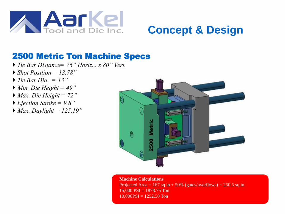
Concept & Design
2500 Metric Ton Machine Specs Tie Bar Distance= 76” Horiz... x 80” Vert.
Shot Position = 13.78”
Tie Bar Dia.. = 13”
Min. Die Height = 49”
Max. Die Height = 72”
Ejection Stroke = 9.8”
Max. Daylight = 125.19”
Machine Calculations
Projected Area = 167 sq in + 50% (gates/overflows) = 250.5 sq in
15,000 PSI = 1878.75 Ton
10,000PSI = 1252.50 Ton
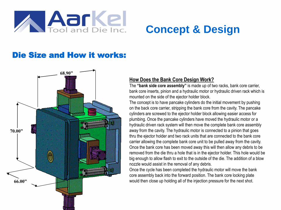
Die Size and How it works:
66.00”
68.90”
How Does the Bank Core Design Work? The “bank side core assembly” is made up of two racks, bank core carrier,
bank core inserts, pinion and a hydraulic motor or hydraulic driven rack which is
mounted on the side of the ejector holder block.
The concept is to have pancake cylinders do the initial movement by pushing
on the back core carrier, stripping the bank core from the cavity. The pancake
cylinders are screwed to the ejector holder block allowing easier access for
plumbing. Once the pancake cylinders have moved the hydraulic motor or a
hydraulic driven rack system will then move the complete bank core assembly
away from the cavity. The hydraulic motor is connected to a pinion that goes
thru the ejector holder and two rack units that are connected to the bank core
carrier allowing the complete bank core unit to be pulled away from the cavity.
Once the bank core has been moved away this will then allow any debris to be
removed from the die thru a hole that is in the ejector holder. This hole would be
big enough to allow flash to exit to the outside of the die. The addition of a blow
nozzle would assist in the removal of any debris.
Once the cycle has been completed the hydraulic motor will move the bank
core assembly back into the forward position. The bank core locking plate
would then close up holding all of the injection pressure for the next shot.
70.00”
Concept & Design
Concept & Design
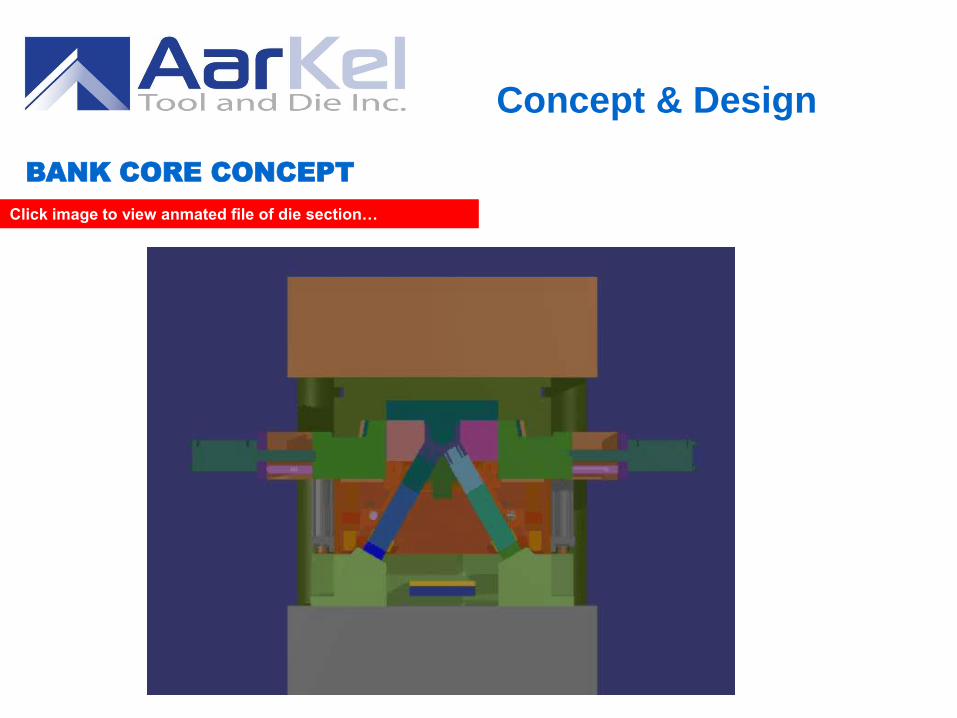
BANK CORE CONCEPT
Click image to view anmated file of die section…

Functionality
Click screen to view animated file of die sequence…

Die Flow and Analysis
Following is a preliminary
simulation to get an
impression about the casting
solidification pattern and
cavity filling conditions.
Pouring temperature - 650C / 1202F
Die temperature to 150C / 300F
Filling and solidification is calculated
in the 1st cycle.
Cavity filling time = 120 msec. Cooling / heating lines are not introduced
Venting was not included in this simulation
Liners are not included at this time.
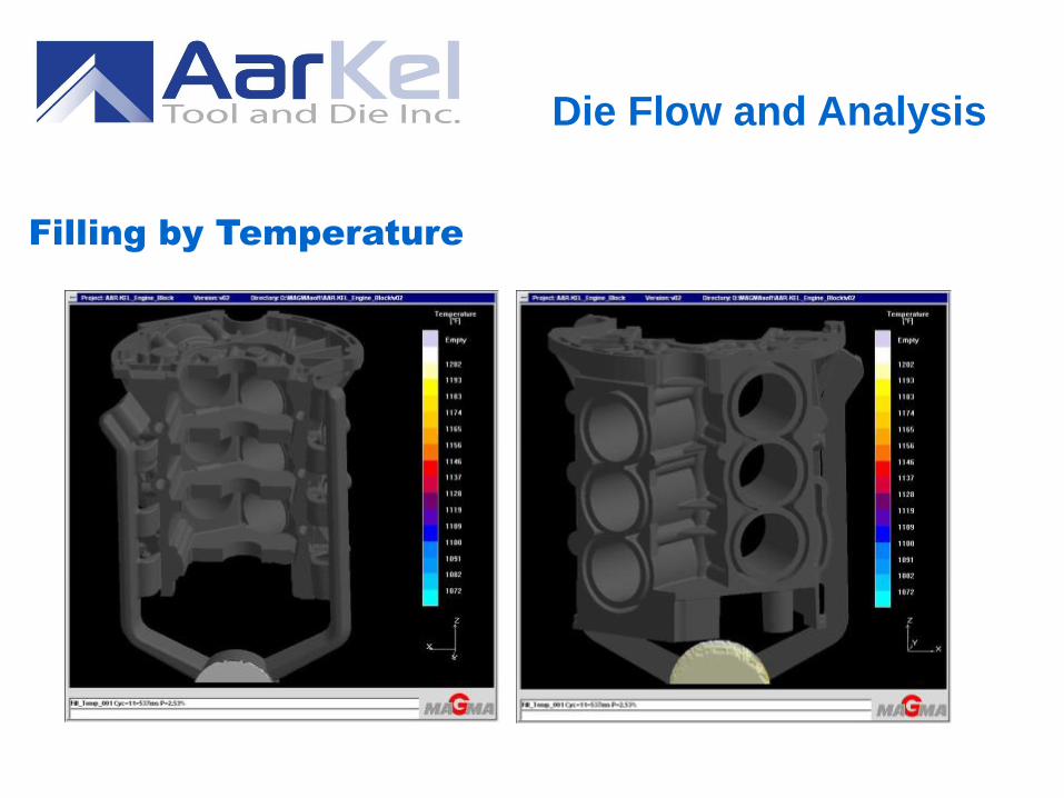
Die Flow and Analysis
Filling by Temperature
Die Flow and Analysis

Die Flow and Analysis
Porosity due to Solidification
Colored locations
solidify later than the
areas around them.
Porosity could be
developed here.
Cooling lines should
be placed close, to
reduce porosity and
increase productivity.

Die Flow and Analysis
CAE - Driven Mold Design and Engineering
GIFU DIE & MOLD ENGINEERING CO.,LTD
F.E.A. analysis on Bank Core
components
Stress
Heat
Solidification
Filling
Die Temperature
Cyclic Cooling Mold Filling
Deformation
Reduction of holder block sizes
Improved of cycle times
Reduced size requirement for D.C.M.
More even die temperatures
Reduced tooling cost
Maximum Material Utilization

Design Validation
CAE – Total Displacement
disp.
Z:0.26
disp. X:-
0.72
disp.
X:0.72
disp.
Y:0.62
disp.
Y:-0.51
@15,000 psi
Large displacement is calculated.
We recommend reinforcing the
cover die by increasing its XY
dimensions.
COVER HOLDER

Design Validation
EJECTOR HOLDER
0.64 0.29
0.17
@15,000 psi
CAE – Total Displacement
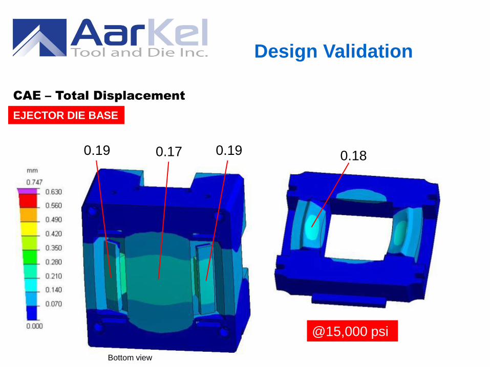
EJECTOR DIE BASE
0.19 0.17 0.18 0.19
Bottom view
@15,000 psi
Design Validation
CAE – Total Displacement

Displacement of Bank Core along the Sliding Direction
(mm)
Section view
Bank Core : 0.61 Block : 0.22
Step of 0.39mm will appear
※The amount of inevitable transformation by compression is
calculated to be 0.43mm
Bank’s total length 840mm x
Young’s modulus 200GPa
Cavity pressure103.43MPa
≒ 0.43mm
direction
0.61
0.18 Oper. bank
The amount of transformation by
compression : 0.43mm
@15,000 psi
(.017”)
(.024”)
(.007”)
Design Validation
CAE – Total Displacement


Overview
We believe Aar-Kel tool and Die Inc. represents the best combination of
value and capability in the die cast tooling industry today.
At Aar-Kel we can provide an unparalleled combination of technical skills
and manufacturing capabilities. Furthermore, by utilizing proven business
partners in lower labor cost countries, we offer customers lower costs
while minimizing the risks.
Let us prove to you why our capabilities and resources are what today's
leading automotive suppliers are looking for in their “full service”
product development partner.

Thank you!
Business Development Manager:
Andrew Stewart
519. 359.7743
President :
Larry Delaey
519. 358.5830
CFO :
Mary VanSantvoort
905 .978.2821
Business Development Manager:
Kevin Van Damme
519. 360.7702
Business Development Manager:
Andrew Spittal
519. 365.4548