wall roughness effects on stagnation-point heat...
TRANSCRIPT

L. A. Gabour
J. H. Lienhard V
W. M. R. Heat and Mass Transfer Laboratory,
Department of Mechanical Engineering, Massachusetts institute of Technology,
Cambridge, MA 02139
Wall Roughness Effects on Stagnation-Point Heat Transfer Beneath an Impinging Liquid Jet Jet impingement cooling applications often involve rough surfaces, yet few studies have examined the role of wall roughness. Surface protrusions can pierce the thermal sublayer in the stagnation region and increase the heat transfer. In this paper, the effect of surface roughness on the stagnation-point heat transfer of an impinging unsubmerged liquid jet is investigated. Experiments were performed in which a fully developed turbulent water jet struck a uniformly heated rough surface. Heat transfer measurements were made for jets of diameters 4.4-9.0 mm over a Reynolds number range of 20,000-84,000. The Prandtl number was held nearly constant at 8.2-9.1. Results are presented for nine well-characterized rough surfaces with root-mean-square average roughness heights ranging from 4.7 to 28.2 fim. Measured values of the local Nusselt number for the rough plates are compared with those for a smooth wall, and increases of as much as 50 percent are observed. Heat transfer in the stagnation zone is scaled with Reynolds number and a roughness parameter. For a given roughness height and jet diameter, the minimum Reynolds number required to increase heat transfer above that of a smooth plate is established. A correlation for smooth wall heat transfer is also given.
Introduction Liquid jet impingement is an effective method for cooling
surfaces owing to the high heat transfer coefficient produced. Among its industrial applications are the hardening and quenching of metals, tempering of glass, and cooling of turbine blades and electronic components. The surface roughness of these materials can play a significant role in the heat transfer, and thus should not be neglected. Hot rolled steel has an average roughness height of 12.5-25 fim (Kalpakjian, 1985) while gas turbine blades can have roughness protrusions ranging from 1.5 to 11 /iin (Taylor, 1990). Wall roughness on the order of only a few microns in height, as for the cases mentioned, can significantly increase the heat transfer by disrupting the thin thermal boundary layer at the stagnation point. Relatively low levels of surface roughness may be expected to be influential, since, for example, this boundary layer can be on the order of 10 im thick for a typical cold water jet. Although numerous investigations of the fluid flow and heat transfer beneath an impinging jet can be found in the literature, the effect of wall roughness has received little or no attention.
One of the few studies of impingement heat transfer to rough surfaces is that of Sullivan et al. (1992) who investigated the use of extended surfaces to augment heat transfer for the cooling of electronic chips. Submerged FC-77 jets of various diameters were used to cool one smooth and two roughened spreader plates attached to simulated electronic circuit chips. The two roughness types investigated were sawcut and dimpled patterns, with roughnesses of 0.30 mm and 0.10-0.30 mm, respectively. Their results cover the full range of smooth to fully rough flow, in which fully rough conditions were assumed to be achieved when the heat transfer reached the same rate of decrease with flow rate as for the smooth surface, following a sharp departure from smooth wall behavior at a lower flow rate. A unit thermal resistance, which accounted for conduction through the plate as well as convection at the surface, was shown to decrease by as much as 60 percent when the plates were roughened.
Contributed by the Heat Transfer Division and presented at the National Heat Transfer Conference, Atlanta, Georgia, August 8-11, 1993. Manuscript received by the Heat Transfer Division April 1993; revision received August 1993. Keywords: Forced Convection, Jets. Associate Technical Editor: A. Faghri.
The present study concentrates on rough-wall stagnation-point heat transfer beneath an impinging turbulent liquid jet. Because the shear stress is zero at the stagnation point (Na-koryakov et al., 1978), standard rough wall theory cannot be applied directly: Typical roughness scaling depends on the friction velocity, u * = \fi\Jp, which vanishes at the stagnation point. Since the stagnation zone flow field is characterized by the strain rate or the radial velocity gradient, B = 2dU/dr (White, 1974; Liu et al., 1992; Stevens et al., 1992), B becomes the dominant scaling parameter in place of the shear stress; near the wall, B produces a viscous length scale proportional to Reynolds number. Other deviations from rough wall turbulent boundary layer theory may result from the very highly accelerated flow near the stagnation point, which would tend to damp boundary layer turbulence originated by either roughness or free-stream turbulence (Moffat and Kays, 1984). Furthermore, the structure of this rough wall boundary layer is not clear. Roughness elements could pierce a sublayer and lower the thermal resistance, thus increasing the heat transfer. However, there is no guarantee of an intrinsically turbulent outer layer in this highly accelerated boundary layer; the role of free-stream turbulence may simply be to disturb the thin thermal boundary layer. If roughness destroys this layer, the fully rough flow condition may be solely dependent on the wall thermal conductivity and roughness size, shape, and spacing, as opposed to being limited by a substantial outer layer mixing process. In the absence of detailed flow measurements, these issues must remain ambiguous.
The present investigation is motivated by the fact that many surfaces that require impingement cooling are rough, while the existing impingement heat transfer correlations apply to smooth surfaces. Experiments were performed to characterize wall roughness effects on heat transfer beneath an unsubmerged turbulent liquid jet impinging normally against a flat, constant heat flux surface. Stagnation-point Nusselt numbers were measured for various Reynolds numbers, jet diameters, and wall roughnesses. As a baseline for comparison, smooth wall data were taken under the same conditions and the effect of nozzle-to-target separation on Nusselt number was briefly investigated. The results of this paper provide Nusselt number as a function of Reynolds number and a dimensionless wall
Journal of Heat Transfer FEBRUARY 1994, Vol. 116/81
Copyright © 1994 by ASMEDownloaded 29 Jun 2009 to 18.80.1.33. Redistribution subject to ASME license or copyright; see http://www.asme.org/terms/Terms_Use.cfm

Rotameters
from Water . _
Reservoir n c f o ) ^
Pump
Pressure (7) Gauge
Plenum
\LJ
II , I'
Heater
\
Honeycomb
Platinum •Resistance Thermometer
Fig. 1 Experimental arrangement
roughness. Suggestions are made for scaling to other Prandtl numbers.
Experimental Apparatus and Procedures Experiments were performed to determine the local Nusselt
number at the stagnation point of a turbulent liquid jet impinging on a rough wall. The experimental apparatus is illustrated schematically in Fig. 1 and consists of a flow loop and an electrically heated target plate. A fully developed, turbulent water jet impinges vertically downward and strikes a uniformly heated, flat, rough surface on which temperature measurements are made. The edges of the sheet are well beyond the stagnation region and do not affect the flow there. With the exception of a few experiments on the effect of nozzle-to-target spacing, the spacing was held constant at l/d= 10.8. Cold water at 12-16°C was used in order to raise the heat transfer and lower the experimental uncertainty in the Nusselt number, as well as to create a narrow Prandtl number range of 8.2-9.1.
The nozzles used to produce the liquid jets were made from tubes of inner diameters 4.4, 6.0, and 9.0 mm. The outlets of the tubes were carefully deburred to create smooth inner walls so that the highly disturbed surfaces of the jets can be attributed exclusively to turbulence. The tubes were 70-110 diameters long in order to ensure fully developed turbulent flow at the outlet. Contraction of these turbulent jets is less than 1.5 percent, so the mean jet diameters can be approximated by the nozzle diameters. The tube diameters were measured with precision calipers and have estimated uncertainties of ±0.2, ±0.7, and ±0.5 percent for the 4.4, 6.0, and 9.0 mm nozzles, re
spectively. (All uncertainties are at a 95 percent confidence level following the ASME Standard, PTC 19.1-1985.)
The liquid flow rate was varied from 0.098 to 0.637 1/s as determined from either of two rotameters connected in parallel in the flow loop. Primary calibration of the rotameters was performed by measuring the time required for a given volume of water to pass through the flow loop into a container. Performance of the rotameters was checked by calculating the jet's velocity, «/, from the pressure reading of a Bourdon-type pressure gage at the top of the plenum. The flow rates were used to calculate the Reynolds number, which varied from 20,000 to 84,000. Uncertainty reached a maximum of ±3.2 percent for the volumetric flow rate and ±5 percent for the Reynolds number.
The jet impinges normally onto an electric heater, which consists of a 0.1016-mm-thick 1010 steel shim instrumented for temperature measurement and connected to a low voltage, high current generator (Fig. 2(a)). A slightly pressurized, hollow plexiglass box beneath the heater prevents water from flowing onto the underside of the shim and minimizes back-losses (which are negligible). The current supplied to the heater and the voltage drop across its length (between the bus bars) were measured. Knowledge of the electrical power dissipated by the heater, together with the heater area between the bus bars, was used to calculate the heat flux, which reached a maximum of 130 kW/m2. As a check on the power measurements, the resistance of the sheets was also monitored while varying the current, giving an average resistance of 2.25 mfl for all the sheets, with individual measurements differing from this value by less than ±0.5 percent. The change in effective shim thickness due to roughening the surfaces had a negligible net effect on the heat flux: While the shim thickness is slightly reduced in the area of the roughness, the current density increases by a proportional amount, offsetting the decrease in total thickness. Uncertainty in the heat flux was an average of ±4.2 percent.
The wall temperature was measured by three 0.076 mm iron-constantan (type J) thermocouples, all located on the back of the heater at the stagnation point, (Fig. 2(b)). The thermocouples were attached to the back of the steel shim and electrically isolated from it by 0.06-mm-thick Kapton tape. This attachment maintains good thermal contact of the thermocouple wires with the plate owing to the low resistance of the tape relative to natural convection resistance on the underside of the plate. Fin effects associated with the three thermocouples were estimated and are negligible.
During the experiments, ten voltage readings were taken for each thermocouple and averaged to reduce random error. The average of the voltages from the three thermocouples was used to calculate the wall temperature. The thermocouples were also calibrated with the heater power off before and after each run to reduce systematic errors. The incoming jet temperature ob-
Nomenclature
B =
B* =
cP = d = dj = h = k =
k* =
kf =
radial velocity gradient = 2(dU/dr) dimensionless radial velocity gradient = 2(dj/u/)(dU/dr) heat capacity of liquid nozzle inner diameter jet diameter «c? heat transfer coefficient rms roughness element height nondimensional roughness height = k/dj thermal conductivity of the impinging liquid
/ =
Nurf =
Pr = Q =
Qw = Red =
r =
Tf = 7mm =
distance between nozzle outlet and target plate Nusselt number based on jet diameter = .qwdj/kf(Tw-Tf) Prandtl number = \x,cp/kf volumetric flow rate of jet wall heat flux Reynolds number of jet = Ufdj/v radial distance from stagnation point incoming jet temperature film temperature = {Tf+Tw)/2
T 1 w t U
u* uf
«/
M V
p T»
wall temperature on liquid side heater sheet thickness radial velocity just outside boundary layer friction velocity = \JT„/P bulk velocity of impinging jet = AQ/itd) thermal boundary layer thickness dynamic viscosity of liquid kinematic viscosity of liquid = n/p liquid density shear stress at wall
82 / Vol. 116, FEBRUARY 1994 Transactions of the ASME
Downloaded 29 Jun 2009 to 18.80.1.33. Redistribution subject to ASME license or copyright; see http://www.asme.org/terms/Terms_Use.cfm

Copper Bus Bars
Generator Leads
Fig. 2(a) Schematic diagram of heater arrangement
Q O
O O
Q O
Q O
Fig. 2(b) Heated sheet as viewed from underside; (c) heated sheet as viewed from above
tained from the thermocouples under isothermal conditions was in agreement with that obtained from a platinum resistance thermometer located in the plenum to within the reading errors of the instruments, verifying that the bulk temperature change of the jet as it travels from the plenum to the target is negligible. A prior calibration of the thermocouples and the platinum resistance thermometer was performed by comparison to a mercury-in-glass thermometer. After calibration, the three devices agreed to within the reading errors of each instrument. The final uncertainty in the measured temperature was ±0.05°C.
The Nusselt number is based on the difference between the wall temperature, T„, and the incoming jet temperature, Tf.
Nurf = - (1) kf{Tw-Tf)
where qw is the wall heat flux and dj is the jet diameter. Since the thermocouples were located on the back of the heater sheet, corrections amounting to no more than 10 percent were made to account for the vertical conductive temperature drop through the sheet (for details see Liu et al., 1991). The corrections were based on the smooth wall sheet thickness, and the reduction in thickness due to the roughness had a negligible effect on this result. Uncertainty in the mean Nusselt number ranged from ±7.5 to ± 10 percent. Radial conduction in the sheet is negligible.
All liquid properties are evaluated at the film temperature, Tn\m-(Tj+ T„)/2, and were obtained from Touloukian (1970).
Complete details of the flow loop, electric heater, calibration procedures, and uncertainty analysis are given by Gabour (1993).
Surface Characterization The rough surfaces were produced by scoring a 3.4 cm2
central portion of the steel shims in four directions in an attempt to simulate natural (homogeneous, isotropic) roughness (the pattern of.scoring is as shown in Fig. 2(c)). This process results in ridges adjacent to the troughs. The ease of fabricating these surfaces contributed to the choice of this type of roughness. The distance between parallel roughness troughs ranged from 0.2 to 1.0 mm.
The nine rough surfaces were characterized by a root-mean-square average roughness as obtained from profiles of the surfaces. A DEKTAK 3030ST with a 2.5 fim radius stylus was used to make the measurements. The DEKTAK is a surface texture measuring system that makes measurements electro-mechanically by moving the sample in a straight line beneath a diamond-tipped stylus. The DEKTAK was carefully calibrated by scanning a standard 1 /xm step and making the necessary adjustments to obtain the correct reading. A scan length of 10 mm and a stylus force of 0.3 N were used. Ten profiles were generated for each surface at intervals of 0.5 mm across the length of the sheet. An rms roughness height was calculated by the DEKTAK along the length of each profile, and the ten squared rms values were averaged. Due to the finite radius of the stylus, the path traced as it scans the surface is in principle smoother than the actual roughness of the surface, However, since the blade used to score the surfaces was triangular with a maximum width of 160 /an, we believe that the stylus was able to resolve the roughness contours accurately. Care was taken during the experiments to ensure that the jets were centered over the area that was used for the surface profiles. The roughness measurements were repeated after the experiments were completed to ensure that the steel shims had not rusted sufficiently to cause changes in any sheet's roughness. The rms roughness heights for the nine rough surfaces ranged from 4.7 to 28.2 nm while the smooth surface had an rms roughness of 0.3 /xm. Some typical surface contours are given by Gabour (1993).
Experimental Results The effect of nozzle-to-target spacing on the smooth wall
stagnation-point Nusselt number was examined for the 4.4 mm nozzle over an lid range of 0.9-19.8. The Nusselt number remained essentially constant over this range, with any slight deviations falling within the uncertainty of the experimental data; thus, a single nozzle-to-target spacing of l/d= 10.8 was employed for the remainder of the experiments.
The smooth wall Nusselt number data for the three nozzles are plotted in Fig. 3(a) and are represented by
Nud = 0.278Re2'633Pr'' (2) to an accuracy of about ± 3 percent. Although the experimental Prandtl number was held nearly constant at 8.2-9.1, the standard high Prandtl number exponent of 1/3 is adopted in this correlation. The smooth wall correlations of Lienhard et al. (1992) and Pan et al. (1992) evaluated at a Prandtl number of 8.3 are included in Fig. 3(c) for comparison. Since the Reynolds number exponent is typically 0.5, Fig. 3(b) shows a comparison of the 0.5 and 0.633 Reynolds number exponent slopes on a log-log plot. Although an exponent of 0.5 may work for Reynolds numbers less than 35,000, 0.633 fits the data over the generally higher Reynolds number range investigated. This may account for some of the disagreement with the previous correlations, which assumed an exponent of 0.5. In addition, the Lienhard et al. (1992) result had an rms scatter of about ± 10
Journal of Heat Transfer FEBRUARY 1994, Vol. 116/83
Downloaded 29 Jun 2009 to 18.80.1.33. Redistribution subject to ASME license or copyright; see http://www.asme.org/terms/Terms_Use.cfm

700
600
d 500
400
300
-
-
:
-/
- 'Bf^
< dj = 4.4 mm
o dj = 6.0 mm
a dj = 9.0 mm
10000 30000 50000 70000 90000
Present Correlation: N\xd = 0.278Re7"Pr"3
- - - -Lienhard, Liu, Gabour( 1992): Nuj = 1.24Rei'2Pr"3
Pan, Stevens, Webb (1992): Nu,, = 0.69 Re,, — j FT0'4
Fig. 3(a) Stagnation-point Nusselt number as a function of Reynolds number showing present data with present and past correlations
1000
Nu,
100
ReJ633 scaling
ReJ5,s scaling
10000 100000
Re,,
Fig. 3(b) Comparison of Reynolds number exponents for Nusselt number correlations
Fig. 3 Smooth wall results
percent, and the more precise results here do lie within the 95 percent confidence limits (2a level) of the previous result.
The rms average roughness values for the ten surfaces are given in Table 1. The Nusselt numbers for each surface are shown in Figs. 4(a-c) as a function of jet Reynolds number for the 4.4, 6.0, and 9.0-mm jets, respectively. As expected, the Nusselt number increases with increasing wall roughness for each diameter, with the roughest surface (S10) producing the highest Nusselt number in all cases. The effect of roughness is clearly dependent on Reynolds number and jet diameter. ,
In general, the Nusselt number data for each surface tend to lie on distinct lines, with slope increasing as roughness increases. An exception occurs for surfaces SI, S2, and S3 in Fig. 4(c). The data from those surfaces lie on essentially the same line, implying that the roughnesses of S2 and S3 are ineffective for increasing heat transfer for the 9.0 mm nozzle. Apparently the roughness elements do not protrude substantially through the thermal sublayer, allowing the surfaces to behave as if they were smooth. At Reynolds numbers higher
Table 1 Root-mean-square roughness heights for the ten heater surfaces. Uncertainties in the rms roughness heights range from ±4.5 to ±9 percent.
SURFACE
SI
S2
• S3
S4
S5
S6
S7
S8
S9
S10
RMS ROUGHNESS (urn)
0.3
4.7
6.3
8.6
13.1
14.1
20.1
25.9
26.5
28.2
than examined for these surfaces, a transitionally rough regime may be reached, in which the roughness elements do disrupt the sublayer, thereby causing the data to rise from this line.
The effect of decreasing Reynolds number is to thicken the thermal boundary layer and thus to reduce the influence of roughness. With the exception of the roughest surfaces—S7 through S10 for the 4.4 mm nozzle and surfaces S9 and S10 for the 6.0 mm nozzle—the Nusselt number data tend to collapse to the smooth wall curve at the lower Reynolds numbers. Presumably these few exceptions also collapse at a lower Reynolds number, but owing to the limited Reynolds number range employed in this study, this presumption cannot be verified.
Differences between the smooth and rough wall data become more pronounced as jet diameter decreases, with results for the 4.4 mm nozzle in Fig. 4(a) showing the largest roughness effects. For example, at a Reynolds number of 40,000 there is a 32 percent increase in the Nusselt number for surface S10 over surface SI for the 4.4 mm nozzle, while at the same Reynolds number the increase is 27 and 14 percent for the 6.0 and 9.0 mm nozzles, respectively. At a Reynolds number of 66,000, the increases rise to 47, 34, and 23 percent, respectively. This behavior can be explained by examining the effective thermal boundary layer thickness as determined from the smooth wall Nusselt number expression (Eq. (2)) with Nud= af,-/ 5,:
«,= 3.60rf,
R e 0.633p r l /3 (3)
As jet diameter decreases, boundary layer thickness decreases. Similarly, as Reynolds number increases, boundary layer thickness decreases. Roughness of a given height, k> is likely to have a greater impact on heat transfer under conditions for which 5, is smaller, since its protrusion into (or through) the thermal boundary layer is greater.
The direct use of 5, as a scaling parameter is problematical. When k«5,, 5, retains a reasonably clear physical meaning (a thermal boundary layer thickness) and we might expect, for example, that a threshold value of k/b, would characterize the onset of roughness effects. When k is near or greater than 5,, 5, lacks a direct physical significance. In this study, k/h, ranges from 0.19 to 4.11. In order to find a more appropriate scaling of the wall roughness, we may apply dimensional analysis.
For the fixed wall material and roughness geometry employed in this study, the dimensional functional equation for the heat transfer coefficient of the rough wall thermal boundary layer is h=f(kf, dj, p, cp, n, Uj, k). Dimensional analysis reveals that the corresponding Nusselt number is a function
84 / Vol. 116, FEBRUARY 1994 Transactions of the ASME
Downloaded 29 Jun 2009 to 18.80.1.33. Redistribution subject to ASME license or copyright; see http://www.asme.org/terms/Terms_Use.cfm

1000
900
800
700
Nu r f 600
500
400
300
-
-
•
A
D
•
•
"n
t
9
i •
* #
0
« x o BDE3' •
« e +
A D *
a
©
0 Q G
e
® +
a •X
•X
ft o
I* o 0 0
•
o
o
X
SI S2
S3 S4 S5
• S6 D S7 * S8 + S9 • S10
20000 40000 60000
Re, 80000 100000
Fig. 4(a) 4.4 mm nozzle
1000
900
800
700
Nu r f 600
500
400
300
-
r-
S A
+ °
* o *
a A
+ • X
"ft 0
1
• +A a
X
V o
*a
X
0 B
+ A *
.+ A •
-*0 * 0
•x * v •o ° B D
0
E
0
B
©
X
° .» • x
\ e
SI S2 S3 S4 S5
+ A
D
• X
•
•
A
+ 0
S6 S7 S8 S9 S10
20000 40000 60000
Re, 80000 100000
Fig. 4(6) 6.0 mm nozzle
10UU
900
800
700
d 600
500
400
300
•
+ • *
Q
»
.•Si ^
OA+
. : > M
0 +
A • X
%
t
0
•F
0
•A D
X
*B 0
• o
m 0
X
+ A
X
X • o
SI S2 S3 S4 S5
• S6 D S7 * S8 + S9 • S10
20000 40000 60000
Rerf
Fig. 4(c) 9.0 mm nozzle
80000 100000
Fig. 4 Stagnation-point Nusselt number for the ten surfaces as a function of Reynolds number
of Reynolds number, Prandtl number, and a roughness parameter, k/dj, which we shall call k* hereinafter. While the ratio of k to some sublayer-type length scale (<5SUb, say) would be a more standard descriptor of roughness effects than k/dj, both ratios will express the same physics if <5SUb=/(Pr, Red, dj). The better engineering parameter is k/dj, which is clearly defined and accurately measurable. Since the Prandtl number was held essentially constant in this study, we can focus on the two remaining independent parameters, Red and k*.
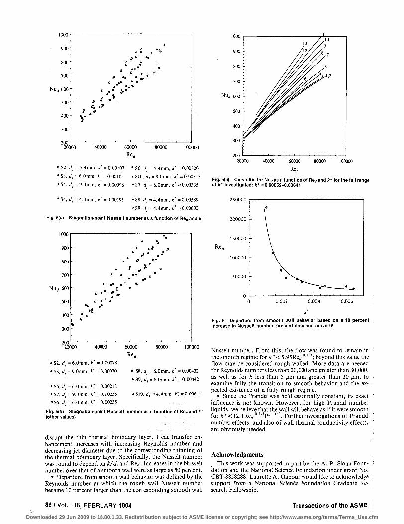
The Nusselt number is plotted as a function of Reynolds number in Figs. 5(a) and 5(6) for a few values of k*. Each value of k* represents and collapses data for different surfaces under different sized nozzles. At a given Reynolds number, the Nusselt number is the same for a given value of k *, lending confidence that no other parameters are involved in the Nusselt number dependence. This also verifies that the ten surfaces are geometrically similar and only differ from one another by the rms height of roughness. Figure 5(c) compares the magnitude of the Nusselt number for the full range of k* investigated, showing fitted curves with the individual data points left out for clarity. The Nusselt number increases with increasing values of A:* and approaches smooth wall behavior as Reynolds number decreases. An exception is curve 6, which crosses some other curves. We note that curve 6 is based on only one diameter and one surface, as opposed to an average of 2 to 4 diameter/surface combinations for the other fitted curves.
Figure 5(c) was compared to Fig. 3(a) to determine a criterion for transition from smooth wall to roughness influenced heat transfer. Departure from smooth wall behavior was taken to occur at the Reynolds number for which the rough wall Nusselt number became 10 percent larger than the corresponding smooth wall Nusselt number. Some of the larger k* curves were extrapolated to lower Reynolds numbers to estimate this value, since those curves appeared to be in the roughness affected regime for the entire Reynolds number range investigated. Figure 6 shows this transition Reynolds number as a function of k*. On the basis of this figure, we estimate that the heat transfer will remain in the smooth regime for
Ar*<5.95Re/'713. (4) Above this value the flow may be considered rough walled.
Since the Prandtl number was held constant for the experiments, its role in the transition criterion is not clear from the data. However, under the rather broad assumption that Eq. (4) is in the form of a k/8, threshold with S,ocPr~1/3, a calculation suggests that the heat transfer may remain in the smooth-wall region for:
£*<12.1Re, -0.173 !Pr- (5) As a result of the limited range of the data, an assessment
of the possible appearance of "fully rough" behavior at high k* or higher Red was not possible.
Conclusions Stagnation-point heat transfer to an unsubmerged turbulent
jet impinging on a rough surface was investigated. The effects of nozzle-to-target spacing, Reynolds number, and wall roughness were examined. Results from nine well-defined rough surfaces were compared to smooth wall data taken under the same conditions.
• The effect of nozzle-to-target separation on the stagnation-point Nusselt number for a smooth wall was found to be negligible over an l/d range of 0.9-19.8, with any variations falling within the experimental uncertainty of the data. The smooth wall Nusselt number is well represented by Nurf = 0.278ReJJ'633Pr1/3 to an accuracy of ±3 percent.
• Heat transfer at the stagnation point can be significantly increased by the presence of roughness elements, which can
Journal of Heat Transfer FEBRUARY 1994, Vol. 116/85
Downloaded 29 Jun 2009 to 18.80.1.33. Redistribution subject to ASME license or copyright; see http://www.asme.org/terms/Terms_Use.cfm
1000
900
800
700
Nud 600
500
400
300
o * 4 *
4> * *>
A •
e . * * B
s • «
200' 20000 40000 60000
Re r f
80000 100000
°S2, dj= 4.4mm, A* =0.00107 • S6, d;.= 4.4mm, *' =0.00320
•S3, rf;-=6.0mm, *' =0.00105 °S10, </y = 9.0mm, A' =0.00313 + S4, dj = 9.0mm, k' = 0.00096 » S7, dj = 6.0mm, *' = 0.00335
•S4, dj =4.4mm, ** =0.00195 »S8, dj =4.4mm, *' =0.00589
°S9, dj = 4.4mm, A' =0.00602
Fig. 5(a) Stagnation-point Nusselt number as a function of Re,, and k'
1000
900
800
700
Nurf 600
500
400
300
200 20000
"
. i
*
'
A
• *A
a *
A
A
A AP
A
s a a •
• • • • •
A D
0 B +
B*
8
40000 60000
Re,, 80000 100000
° S8, dj = 6.0mm, *' = 0.00432
» S9, rfy = 6.0mm, *' = 0.00442
»S10, */, = 4.4mm, k' =0.00641
• S2, dj = 6.0mm, *' = 0.00078
•S3, dt• = 9.0mm, A' =0.00070
+ S5, rf,=6.0mm, *' =0.00218
•S7, Jy = 9.0mm, A' =0.00235
•S6, dj = 6.0mm, *" =0.00235
Fig. 5(b) Stagnation-point Nusselt number as a function of Red and k* (other values)
disrupt the thin thermal boundary layer. Heat transfer enhancement increases with increasing Reynolds number and decreasing jet diameter due to the corresponding thinning of the thermal boundary layer. Specifically, the Nusselt number was found to depend on k/dj and Red. Increases in the Nusselt number over that of a smooth wall were as large as 50 percent.
• Departure from smooth wall behavior was defined by the Reynolds number at which the rough wall Nusselt number became 10 percent larger than the corresponding smooth wall
100000
Fig. 5(c) Curve-fits for Nudas a function of Red and k* for the full range of k' investigated: k* = 0.00052-0.00641
250000
200000 -
Re, 150000
100000
50000 -
0.002 0.004 0.006
Fig. 6 Departure from smooth wall behavior based on a 10 percent increase in Nusselt number: present data and curve fit
Nusselt number. From this, the flow was found to remain in the smooth regime for k* < 5.95Red~
0,713; beyond this value the flow may be considered rough walled. More data are needed for Reynolds numbers less than 20,000 and greater than 80,000, as well as for k less than 5 ^m and greater than 30 (im, to examine fully the transition to smooth behavior and the expected existence of a fully rough regime.
• Since the Prandtl was held essentially constant, its exact influence is not known. However, for high Prandtl number liquids, we believe that the wall will behave as if it were smooth for k* < 12.1Red °-713pr1/3. Further investigations of Prandtl number effects, and also of wall thermal conductivity effects, are obviously needed.
Acknowledgments This work was supported in part by the A. P. Sloan Foun
dation and the National Science Foundation under grant No. CBT-8858288. Laurette A. Gabour would like to acknowledge support from a National Science Foundation Graduate Research Fellowship.
86 / Vol. 116, FEBRUARY 1994 Transactions of the ASME
Downloaded 29 Jun 2009 to 18.80.1.33. Redistribution subject to ASME license or copyright; see http://www.asme.org/terms/Terms_Use.cfm

References
Oabour, L. A., 1993, "The Effects of Surface Roughness on Stagnation-Point Heat Transfer During Impingement of Turbulent Liquid Jets," Master's Thesis in Mechanical Engineering, Massachusetts Institute of Technology, Cambridge, MA.
Kalpakjian, S., 1985, Manufacturing Processes for Engineering Materials, Addison-Wesley Publishing Company, Inc.,' Reading, MA, pp. 180-194.
Lienhard V, J. H., Liu, X., and Gabour, L. A., 1992, "Splattering and Heat Transfer During Impingement of a Turbulent Liquid Jet ," ASME JOURNAL OF HEAT TRANSFER, Vol. 114, pp. 362-372.
Liu, X.,.Lienhard V, J. H., and Lombara, J. S. Transfer by Impingement of Circular Liquid Jets, TRANSFER, Vol. 113, pp. 571-582.
Liu, X., Gabour, L. A., and Lienhard V, J. H., 1992, "Stagnation Point Heat Transfer During Impingement of Laminar Liquid Jets: Analysis With Surface Tension Effects," General Papers in Heat Transfer, ASME HTD-Vol. 204, pp. 173-182.
Moffat, R. J., and Kays, W. M., 1984, "A Review of Turbulent-Boundary-Layer Heat Transfer Research at Stanford, 1958-1983," Advances in Heat Transfer, Vol. 16, pp. 241-365.
Nakoryakov, V. E., Pokusaev, B. G., andTroyan, E. N., 1978, "Impingement
1991, "Convective Heat ASME JOURNAL OF HEAT
of an Axisymmetric Liquid Jet on a Barrier," Int. J. Heat Mass Transfer, Vol. 21, pp. 1175-1184.
Pan, Y., Stevens, J., and Webb, B. W., 1992, "Effect of Nozzle Configuration on Transport in the Stagnation Zone of Axisymmetric, Impinging Free-Surface Liquid Jets: Part 2—Local Heat Transfer," ASME JOURNAL OF HEAT TRANSFER, Vol. 114, pp. 880-886.
Stevens, J., and Webb, B. W., 1991, "Local Heat Transfer Coefficients Under an Axisymmetric, Single-Phase Liquid Jet ," ASME JOURNAL OF HEAT TRANSFER, Vol. 113, pp. 71-78.
Stevens, J., Pan, Y., and Webb, B. W., 1992, "Effect of Nozzle Configuration on Transport in the Stagnation Zone of Axisymmetric, Impinging Free-Surface Liquid Jets: Part .1—Turbulent Flow Structure," ASME JOURNAL OF HEAT TRANSFER, Vol. 114, pp. 874-879.
Sullivan, P. F., Ramadhyani, S., and Incropera, F. P., 1992, "Use of Smooth and Roughened Spreader Plates to Enhance Impingement Cooling of Small Heat Sources With Single Circular Liquid Jets," Session on Direct and Indirect Cooling Techniques in Electronic Packaging, 28th ASME/AIChE National Heat Transfer Conference, San Diego, CA.
Taylor, R. P., 1990, "Surface Roughness Measurements on Gas Turbine Blades," ASME Journal of Turbomachinery, Vol. 112, pp. 175-180.
Touloukian, Y. S., 1970, Thermophysical Properties of Matter, Purdue University, West Lafayette, IN, Vol. 3, p. 120; Vol. 11, p. 94.
White, F. M., 1974, Viscous Fluid Flow, McGraw-Hill, New York.
Subscribe to
Journal of Electronic Packaging
This ASME Transactions Journal covers the following: stress analysis and micro-mechanics; heat transfer and fluid flow for thermal management; physical design; reliability and failure prevention; surface mount technology and solder joints; dynamics, shock and vibration; materials and processing; computer-aided engineering; manufacturing and automation; environmental protection; economics.
Published quarterly: March • June • September • December $110/yr. non-members $40/yr. ASME members
To order: write ASME Information Central, 22 Law Drive, Box 2300, Fairfield, NJ 07007-2300 or call 800-THE-ASME (843-2763) or fax 201-882-1717.
Journal of Heat Transfer FEBRUARY 1994, Vol. 116/87
Downloaded 29 Jun 2009 to 18.80.1.33. Redistribution subject to ASME license or copyright; see http://www.asme.org/terms/Terms_Use.cfm