wall mounted gas boiler - dunkirk boilers application guide rev a... · wall mounted gas boiler....
TRANSCRIPT

Models CHB/CCB
APPLICATION GUIDE
PN 240011074 REV A [08/31/2015]
Manufactured for:ECR International, Inc.
2201 Dwyer Avenue, Utica NY 13501web site: www.ecrinternational.com
WALL MOUNTEDGAS BOILER
This manual has been prepared for use with the appropriate Installation, Operation and Maintenance Manual.
For use with CCB/CHB Boilers ONLY.
2 PN 240011074 [08/31/2015]
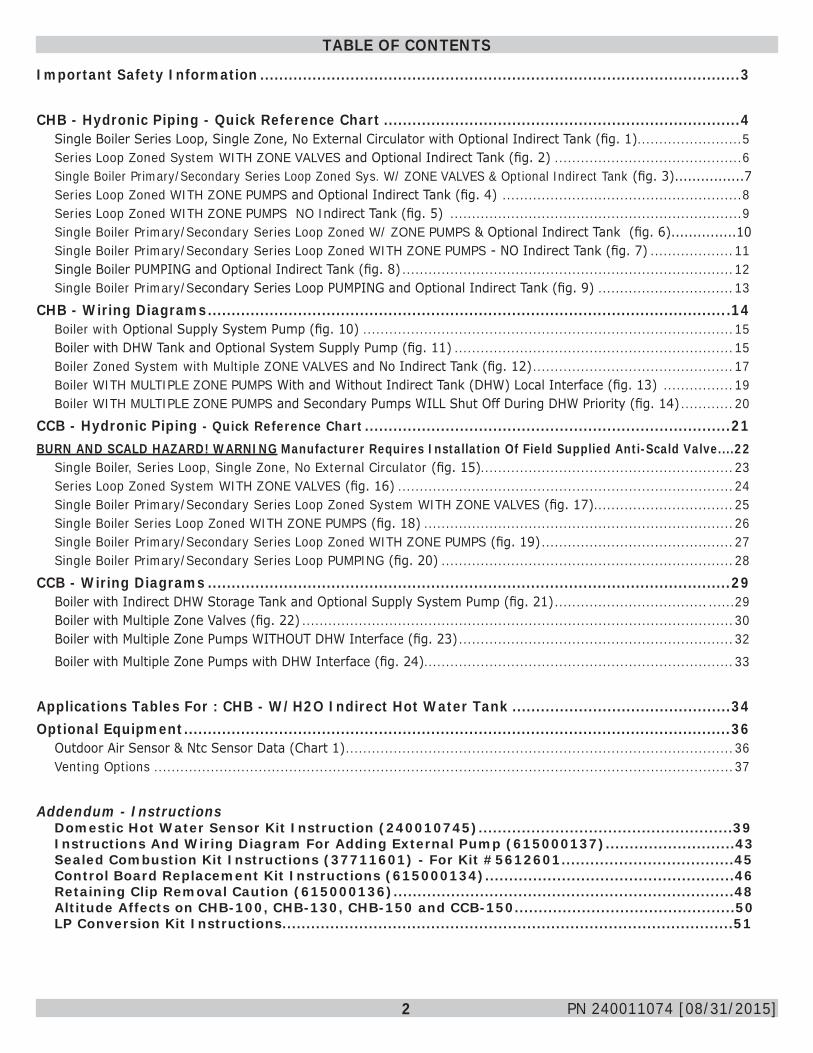
TABLE OF CONTENTS
Important Safety Information .....................................................................................................3
CHB - Hydronic Piping - Quick Reference Chart ...........................................................................4Single Boiler Series Loop, Single Zone, No External Circulator with Optional Indirect Tank (fig. 1) ........................5Series Loop Zoned System WITH ZONE VALVES and Optional Indirect Tank (fig. 2) ...........................................6Single Boiler Primary/Secondary Series Loop Zoned Sys. W/ ZONE VALVES & Optional Indirect Tank (fig. 3)................7Series Loop Zoned WITH ZONE PUMPS and Optional Indirect Tank (fig. 4) .......................................................8Series Loop Zoned WITH ZONE PUMPS NO Indirect Tank (fig. 5) ...................................................................9Single Boiler Primary/Secondary Series Loop Zoned W/ ZONE PUMPS & Optional Indirect Tank (fig. 6)...............10Single Boiler Primary/Secondary Series Loop Zoned WITH ZONE PUMPS - NO Indirect Tank (fig. 7) ...................11Single Boiler PUMPING and Optional Indirect Tank (fig. 8) ............................................................................12Single Boiler Primary/Secondary Series Loop PUMPING and Optional Indirect Tank (fig. 9) ...............................13
CHB - Wiring Diagrams ..............................................................................................................14Boiler with Optional Supply System Pump (fig. 10) .....................................................................................15Boiler with DHW Tank and Optional System Supply Pump (fig. 11) ................................................................15Boiler Zoned System with Multiple ZONE VALVES and No Indirect Tank (fig. 12) ..............................................17Boiler WITH MULTIPLE ZONE PUMPS With and Without Indirect Tank (DHW) Local Interface (fig. 13) ................19Boiler WITH MULTIPLE ZONE PUMPS and Secondary Pumps WILL Shut Off During DHW Priority (fig. 14) ............20
CCB - Hydronic Piping - Quick Reference Chart .............................................................................21BURN AND SCALD HAZARD! WARNING Manufacturer Requires Installation Of Field Supplied Anti-Scald Valve....22
Single Boiler, Series Loop, Single Zone, No External Circulator (fig. 15)..........................................................23Series Loop Zoned System WITH ZONE VALVES (fig. 16) .............................................................................24Single Boiler Primary/Secondary Series Loop Zoned System WITH ZONE VALVES (fig. 17) ................................25Single Boiler Series Loop Zoned WITH ZONE PUMPS (fig. 18) .......................................................................26Single Boiler Primary/Secondary Series Loop Zoned WITH ZONE PUMPS (fig. 19) ............................................27Single Boiler Primary/Secondary Series Loop PUMPING (fig. 20) ...................................................................28
CCB - Wiring Diagrams ..............................................................................................................29Boiler with Indirect DHW Storage Tank and Optional Supply System Pump (fig. 21) ................................... ......29Boiler with Multiple Zone Valves (fig. 22) ...................................................................................................30Boiler with Multiple Zone Pumps WITHOUT DHW Interface (fig. 23) ...............................................................32Boiler with Multiple Zone Pumps with DHW Interface (fig. 24) .......................................................................33
Applications Tables For : CHB - W/H2O Indirect Hot Water Tank ..............................................34Optional Equipment ...................................................................................................................36
Outdoor Air Sensor & Ntc Sensor Data (Chart 1) .........................................................................................36Venting Options .....................................................................................................................................37
Addendum - InstructionsDomestic Hot Water Sensor Kit Instruction (240010745).....................................................39Instructions And Wiring Diagram For Adding External Pump (615000137)...........................43Sealed Combustion Kit Instructions (37711601) - For Kit #5612601....................................45Control Board Replacement Kit Instructions (615000134)....................................................46Retaining Clip Removal Caution (615000136).......................................................................48Altitude Affects on CHB-100, CHB-130, CHB-150 and CCB-150..............................................50LP Conversion Kit Instructions..............................................................................................51
3 PN 240011074 [08/31/2015]
IMPORTANT SAFETY INFORMATION
NOTICEUsed to address practices not related to personal injury.
CAUTIONIndicates a hazardous situation which, if not avoided, could result in minor or moderate injury.
!
WARNINGIndicates a hazardous situation which, if not avoided, could result in death or serious injury.
!
DANGERIndicates a hazardous situation which, if not avoided, WILL result in death or serious injury.
!
This is the safety alert symbol. Symbol alerts you to potential personal injury hazards. Obey all safety messages following this symbol to avoid possible injury or death.
2. Become familiar with symbols identifyingpotential hazards.
1. GeneralBoiler installation shall be completed by qualified agency. See Installation, Operation & Maintenance Manual for additional information.
WARNINGFire, explosion, asphyxiation and electrical shock hazard. Improper installation could result in death or serious injury. Read this manual and understand all requirements before beginning installation.
!
3. Installation shall conform to requirements of authority having jurisdiction or in absence of such requirements:• United States
• National Fuel Gas Code, ANSI Z223.1/NFPA 54.
• National Electrical Code, NFPA 70.• Canada
• Natural Gas and Propane Installation Code, CAN/CSA B149.1.
• Canadian Electrical Code, Part I, Safety Standard for Electrical Installations, CSA C22.1
4. Where required by authority having jurisdiction, installation shall conform to Standard for Controls and Safety Devices for Automatically Fired Boilers, ANSI/ASME CSD-1. Additional manual reset low water cutoff may be required.
5. Requirements for Commonwealth of Massachusetts: Boiler installation must conform to Commonwealth of Massachusetts code 248 CMR which includes but is not limited to:• Installation by licensed plumber or gas fitter.
4 PN 240011074 [08/31/2015]
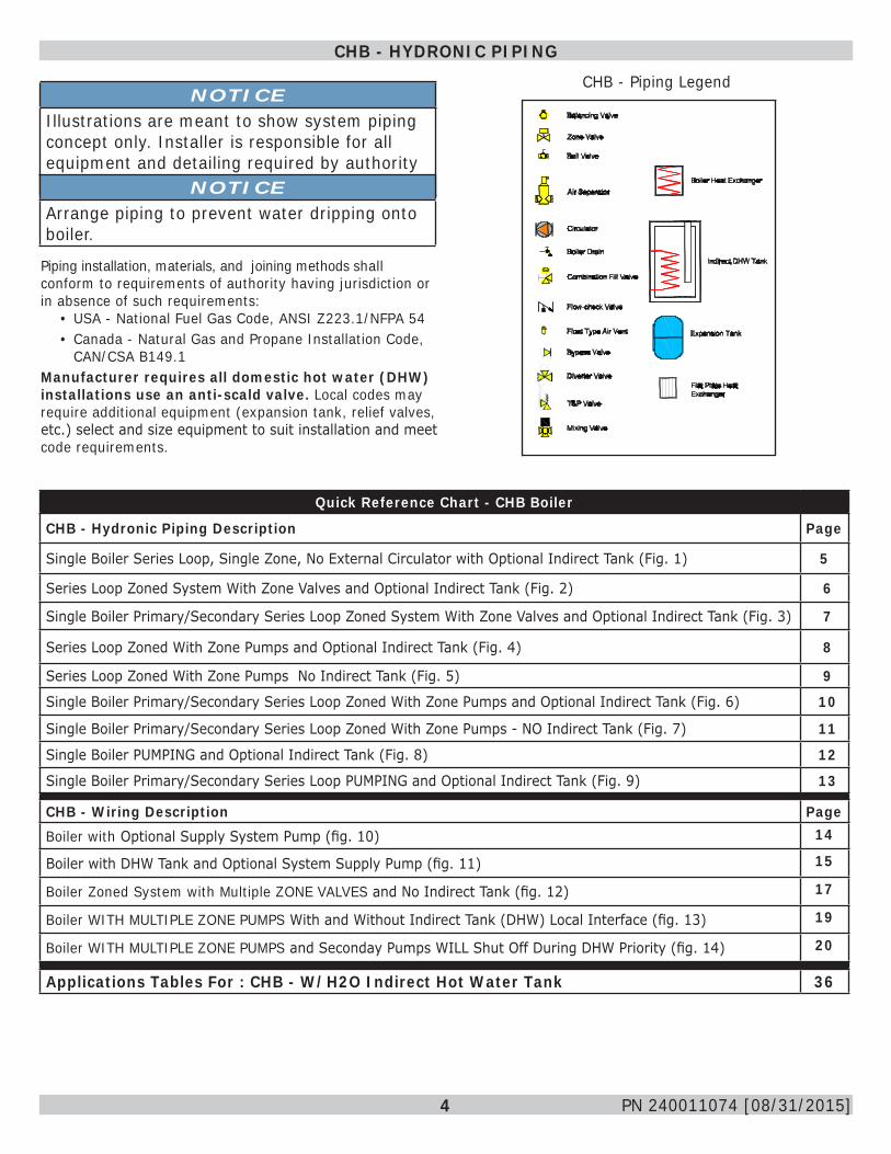
CHB - HYDRONIC PIPINGCHB - Piping Legend
NOTICEIllustrations are meant to show system piping concept only. Installer is responsible for all equipment and detailing required by authority having jurisdiction.NOTICEArrange piping to prevent water dripping onto boiler.
Quick Reference Chart - CHB Boiler
CHB - Hydronic Piping Description Page
Single Boiler Series Loop, Single Zone, No External Circulator with Optional Indirect Tank (Fig. 1) 5
Series Loop Zoned System With Zone Valves and Optional Indirect Tank (Fig. 2) 6
Single Boiler Primary/Secondary Series Loop Zoned System With Zone Valves and Optional Indirect Tank (Fig. 3) 7
Series Loop Zoned With Zone Pumps and Optional Indirect Tank (Fig. 4) 8
Series Loop Zoned With Zone Pumps No Indirect Tank (Fig. 5) 9
Single Boiler Primary/Secondary Series Loop Zoned With Zone Pumps and Optional Indirect Tank (Fig. 6) 10
Single Boiler Primary/Secondary Series Loop Zoned With Zone Pumps - NO Indirect Tank (Fig. 7) 11
Single Boiler PUMPING and Optional Indirect Tank (Fig. 8) 12
Single Boiler Primary/Secondary Series Loop PUMPING and Optional Indirect Tank (Fig. 9) 13
CHB - Wiring Description PageBoiler with Optional Supply System Pump (fig. 10) 14
Boiler with DHW Tank and Optional System Supply Pump (fig. 11) 15
Boiler Zoned System with Multiple ZONE VALVES and No Indirect Tank (fig. 12) 17
Boiler WITH MULTIPLE ZONE PUMPS With and Without Indirect Tank (DHW) Local Interface (fig. 13) 19
Boiler WITH MULTIPLE ZONE PUMPS and Seconday Pumps WILL Shut Off During DHW Priority (fig. 14) 20
Applications Tables For : CHB - W/H2O Indirect Hot Water Tank 36
Piping installation, materials, and joining methods shall conform to requirements of authority having jurisdiction or in absence of such requirements:
• USA - National Fuel Gas Code, ANSI Z223.1/NFPA 54• Canada - Natural Gas and Propane Installation Code,
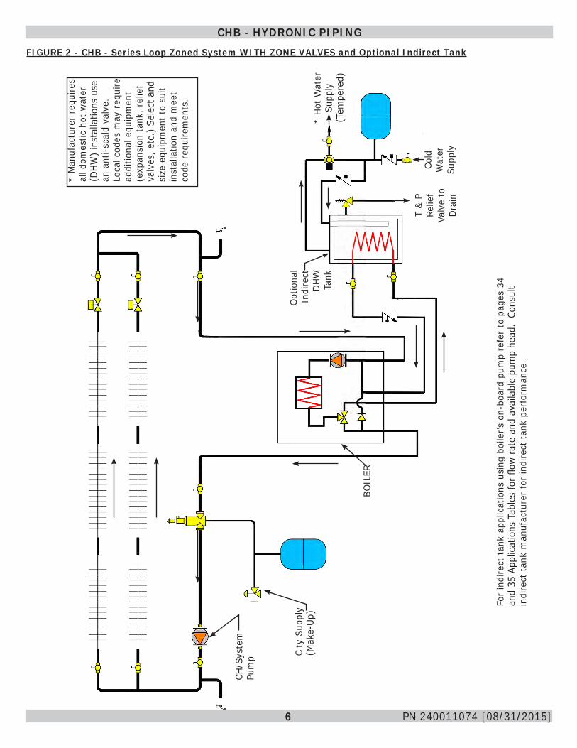
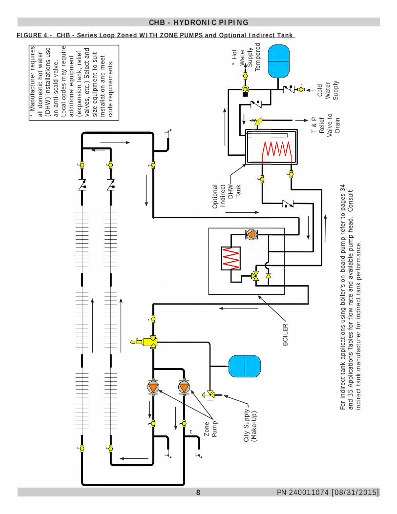
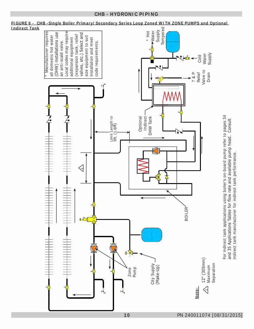
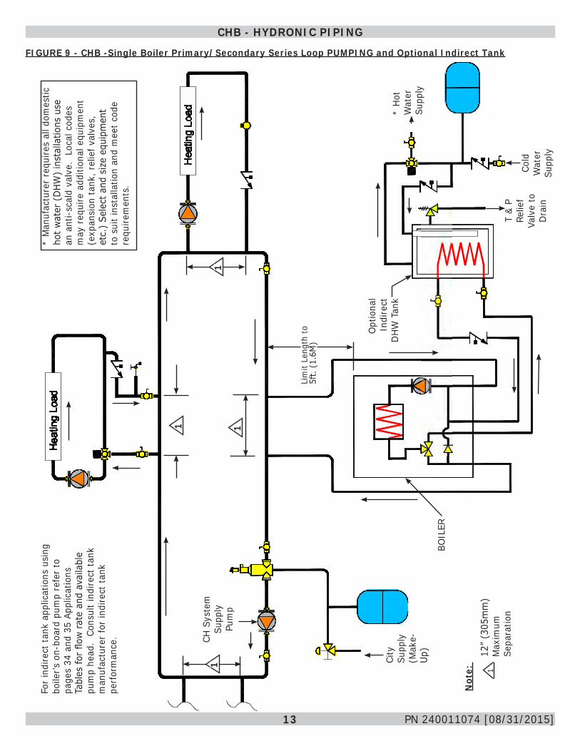
CAN/CSA B149.1Manufacturer requires all domestic hot water (DHW) installations use an anti-scald valve. Local codes may require additional equipment (expansion tank, relief valves, etc.) select and size equipment to suit installation and meet code requirements.

5 PN 240011074 [08/31/2015]
CHB - HYDRONIC PIPINGFIGURE 1 - CHB - Single Boiler Series Loop, Single Zone, No External Circulator with Optional Indirect Tank
City
Sup
ply
(Mak
e-Up
)
BOIL
ER
Opt
iona
l In
dire
ct
DHW
Ta
nk*
Hot W
ater
Su
pply
Te
mpe
red
Cold
W
ater
Su
pply
T &
P Re
lief
Valv
e to
D
rain
Note
: Fi
eld
supp
lied
circ
ulat
or r
equi
red
if he
ad-lo
ss e
xcee
ds 8
Fe
et a
t 6 G
PM.
* M
anuf
actu
rer
requ
ires
all d
omes
tic h
ot w
ater
(D
HW)
inst
alla
tions
use
an
ant
i-sca
ld v
alve
. Lo
cal c
odes
may
req
uire
ad
ditio
nal e
quip
men
t (e
xpan
sion
tank
, rel
ief
valv
es, e
tc.)
Sel
ect a
nd
size
equ
ipm
ent t
o su
it in
stal
latio
n an
d m
eet
code
req
uire
men
ts.
For
indi
rect
tank
app
licat
ions
usi
ng b
oile
r’s o
n-bo
ard
pum
p re
fer
to p
ages
34
and
35 A
pplic
atio
ns T
able
s fo
r flo
w r
ate
and
avai
labl
e pu
mp
head
. Co
nsul
t in
dire
ct ta
nk m
anuf
actu
rer
for
indi
rect
tank
per
form
ance
.
6 PN 240011074 [08/31/2015]
CHB - WIRING DIAGRAMFIGURE 2 - CHB - Series Loop Zoned System WITH ZONE VALVES and Optional Indirect Tank
CHB - HYDRONIC PIPING
City
Sup
ply
(Mak
e-Up
)
BOIL
ER
Opt
iona
lIn
dire
ct
DHW
Ta
nk
Cold
W
ater
Su
pply
CH/S
yste
m
Pum
p
T &
P Re
lief
Valv
e to
D
rain
* Ho
t Wat
er
Supp
ly
(Tem
pere
d)
* M
anuf
actu
rer
requ
ires
all d
omes
tic h
ot w
ater
(D
HW)
inst
alla
tions
use
an
ant
i-sca
ld v
alve
. Lo
cal c
odes
may
req
uire
ad
ditio
nal e
quip
men
t (e
xpan
sion
tank
, rel
ief
valv
es, e
tc.)
Sel
ect a
nd
size
equ
ipm
ent t
o su
it in
stal
latio
n an
d m
eet
code
req
uire
men
ts.
For
indi
rect
tank
app
licat
ions
usi
ng b
oile
r’s o
n-bo
ard
pum
p re
fer
to p
ages
34
and
35 A
pplic
atio
ns T
able
s fo
r flo
w r
ate
and
avai
labl
e pu
mp
head
. Co
nsul
t in
dire
ct ta
nk m
anuf
actu
rer
for
indi
rect
tank
per
form
ance
.

7 PN 240011074 [08/31/2015]
FIGURE 3 - CHB - Single Boiler Primary/Secondary Series Loop Zoned System WITH ZONE VALVES and Optional Indirect Tank
CHB - HYDRONIC PIPING
City
Sup
ply
(Mak
e-Up
)
BOIL
ER
Opt
iona
l In
dire
ct
DHW
Ta
nk*H
ot W
ater
Su
pply
(T
empe
red)
Cold
W
ater
Su
pply
CH/S
yste
m
Pum
p
Lim
it Le
ngth
to
5ft.
(1.
6M)
1
T &
P Re
lief
Valv
e to
D
rain
Not
e:
112
” (3
05m
m)
Max
imum
Se
para
tion
* M
anuf
actu
rer
requ
ires
all d
omes
tic h
ot w
ater
(D
HW)
inst
alla
tions
use
an
ant
i-sca
ld v
alve
. Lo
cal c
odes
may
req
uire
ad
ditio
nal e
quip
men
t (e
xpan
sion
tank
, rel
ief
valv
es, e
tc.)
Sel
ect a
nd
size
equ
ipm
ent t
o su
it in
stal
latio
n an
d m
eet
code
req
uire
men
ts.
For
indi
rect
tank
app
licat
ions
usi
ng b
oile
r’s o
n-bo
ard
pum
p re
fer
to p
ages
34
and
35 A
pplic
atio
ns T
able
s fo
r flo
w r
ate
and
avai
labl
e pu
mp
head
. Co
nsul
t in
dire
ct ta
nk m
anuf
actu
rer
for
indi
rect
tank
per
form
ance
.
8 PN 240011074 [08/31/2015]
FIGURE 4 - CHB - Series Loop Zoned WITH ZONE PUMPS and Optional Indirect Tank
CHB - HYDRONIC PIPING
1
T &
P Re
lief
Valv
e to
D
rain
Cold
W
ater
Su
pply
Opt
iona
l In
dire
ct
DHW
Ta
nk
BOIL
ER
City
Sup
ply
(Mak
e-Up
)
Zone
Pu
mp
* Ho
t W
ater
Su
pply
Te
mpe
red
* M
anuf
actu
rer
requ
ires
all d
omes
tic h
ot w
ater
(D
HW)
inst
alla
tions
use
an
ant
i-sca
ld v
alve
. Lo
cal c
odes
may
req
uire
ad
ditio
nal e
quip
men
t (e
xpan
sion
tank
, rel
ief
valv
es, e
tc.)
Sel
ect a
nd
size
equ
ipm
ent t
o su
it in
stal
latio
n an
d m
eet
code
req
uire
men
ts.
For
indi
rect
tank
app
licat
ions
usi
ng b
oile
r’s o
n-bo
ard
pum
p re
fer
to p
ages
34
and
35 A
pplic
atio
ns T
able
s fo
r flo
w r
ate
and
avai
labl
e pu
mp
head
. Co
nsul
t in
dire
ct ta
nk m
anuf
actu
rer
for
indi
rect
tank
per
form
ance
.

9 PN 240011074 [08/31/2015]
FIGURE 5 - CHB - Series Loop Zoned WITH ZONE PUMPS NO Indirect Tank
CHB - HYDRONIC PIPING
1
BOIL
ER
City
Sup
ply
(Mak
e-Up
)
Zone
Pu
mp
10 PN 240011074 [08/31/2015]
FIGURE 6 - CHB -Single Boiler Primary/Secondary Series Loop Zoned WITH ZONE PUMPS and Optional Indirect Tank
CHB - HYDRONIC PIPING
T &
P Re
lief
Valv
e to
D
rain
Cold
W
ater
Su
pply
Opt
iona
l In
dire
ct
DHW
Tan
k
BOIL
ER
City
Sup
ply
(Mak
e-Up
)
Lim
it Le
ngth
to
5ft.
(1.
6M)
Zone
Pu
mp
1
Not
e:
112
” (3
05m
m)
Max
imum
Se
para
tion
* Ho
t W
ater
Su
pply
Te
mpe
red
* M
anuf
actu
rer
requ
ires
all d
omes
tic h
ot w
ater
(D
HW)
inst
alla
tions
use
an
ant
i-sca
ld v
alve
. Lo
cal c
odes
may
req
uire
ad
ditio
nal e
quip
men
t (e
xpan
sion
tank
, rel
ief
valv
es, e
tc.)
Sel
ect a
nd
size
equ
ipm
ent t
o su
it in
stal
latio
n an
d m
eet
code
req
uire
men
ts.
For
indi
rect
tank
app
licat
ions
usi
ng b
oile
r’s o
n-bo
ard
pum
p re
fer
to p
ages
34
and
35 A
pplic
atio
ns T
able
s fo
r flo
w r
ate
and
avai
labl
e pu
mp
head
. Co
nsul
t in
dire
ct ta
nk m
anuf
actu
rer
for
indi
rect
tank
per
form
ance
.
11 PN 240011074 [08/31/2015]
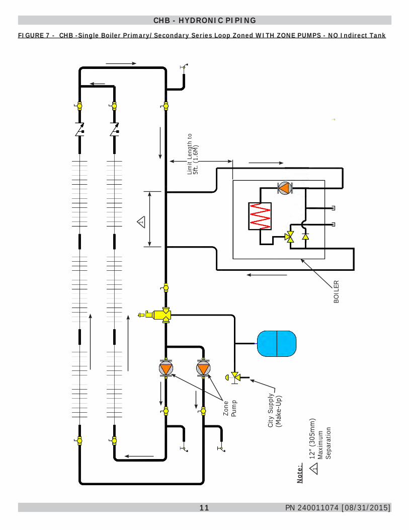
FIGURE 7 - CHB -Single Boiler Primary/Secondary Series Loop Zoned WITH ZONE PUMPS - NO Indirect Tank
CHB - HYDRONIC PIPING
Lim
it Le
ngth
to
5ft.
(1.
6M)
BOIL
ER
City
Sup
ply
(Mak
e-Up
)
Zone
Pu
mp
1
Not
e:
112
” (3
05m
m)
Max
imum
Se
para
tion

12 PN 240011074 [08/31/2015]
FIGURE 8 - CHB -Single Boiler PUMPING and Optional Indirect Tank
CHB - HYDRONIC PIPING
T &
P Re
lief
Valv
e to
D
rain
Cold
W
ater
Su
pply
Opt
iona
lIn
dire
ct
DHW
Tan
k
BOIL
ER
City
Su
pply
(M
ake-
Up)
CH S
yste
m
Supp
ly
Pum
p
* Ho
t W
ater
Su
pply
Te
mpe
red
Not
e:
1
12”
(305
mm
) M
axim
um
Sepa
ratio
n
1
11
* M
anuf
actu
rer
requ
ires
all d
omes
tic
hot w
ater
(D
HW)
inst
alla
tions
use
an
ant
i-sca
ld v
alve
. Lo
cal c
odes
m
ay r
equi
re a
dditi
onal
equ
ipm
ent
(exp
ansi
on ta
nk, r
elie
f val
ves,
et
c.)
Sele
ct a
nd s
ize
equi
pmen
t to
sui
t ins
talla
tion
and
mee
t cod
e re
quire
men
ts.
For
indi
rect
tank
app
licat
ions
usi
ng
boile
r’s o
n-bo
ard
pum
p re
fer
to
page
s 34
and
35
Appl
icat
ions
Ta
bles
for
flow
rat
e an
d av
aila
ble
pum
p he
ad.
Cons
ult i
ndire
ct ta
nk
man
ufac
ture
r fo
r in
dire
ct ta
nk
perf
orm
ance
.
13 PN 240011074 [08/31/2015]
CHB - HYDRONIC PIPING
FIGURE 9 - CHB -Single Boiler Primary/Secondary Series Loop PUMPING and Optional Indirect Tank
CH S
yste
m
Supp
ly
Pum
p
T &
P Re
lief
Valv
e to
D
rain
Cold
W
ater
Su
pply
* Ho
t W
ater
Su
pply
BOIL
ER
City
Su
pply
(M
ake-
Up)
Lim
it Le
ngth
to
5ft.
(1.
6M)
Not
e:
1
Opt
iona
lIn
dire
ct
DHW
Tan
k
11
11
12”
(305
mm
) M
axim
um
Sepa
ratio
n
* M
anuf
actu
rer
requ
ires
all d
omes
tic
hot w
ater
(D
HW)
inst
alla
tions
use
an
ant
i-sca
ld v
alve
. Lo
cal c
odes
m
ay r
equi
re a
dditi
onal
equ
ipm
ent
(exp
ansi
on ta
nk, r
elie
f val
ves,
et
c.)
Sele
ct a
nd s
ize
equi
pmen
t to
sui
t ins
talla
tion
and
mee
t cod
e re
quire
men
ts.
For
indi
rect
tank
app
licat
ions
usi
ng
boile
r’s o
n-bo
ard
pum
p re
fer
to
page
s 34
and
35
Appl
icat
ions
Ta
bles
for
flow
rat
e an
d av
aila
ble
pum
p he
ad.
Cons
ult i
ndire
ct ta
nk
man
ufac
ture
r fo
r in
dire
ct ta
nk
perf
orm
ance
.
14 PN 240011074 [08/31/2015]
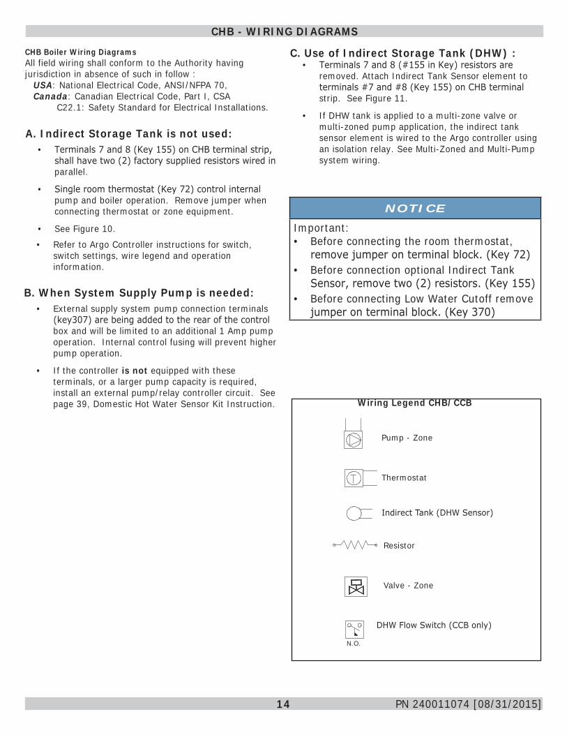
CHB Boiler Wiring DiagramsAll field wiring shall conform to the Authority having jurisdiction in absence of such in follow :
USA: National Electrical Code, ANSI/NFPA 70, Canada: Canadian Electrical Code, Part I, CSA C22.1: Safety Standard for Electrical Installations. A. Indirect Storage Tank is not used:• Terminals 7 and 8 (Key 155) on CHB terminal strip,
shall have two (2) factory supplied resistors wired in parallel.
• Single room thermostat (Key 72) control internal pump and boiler operation. Remove jumper when connecting thermostat or zone equipment.
• See Figure 10.
CHB - WIRING DIAGRAMS
• Refer to Argo Controller instructions for switch, switch settings, wire legend and operation information.
B. When System Supply Pump is needed:• External supply system pump connection terminals
(key307) are being added to the rear of the control box and will be limited to an additional 1 Amp pump operation. Internal control fusing will prevent higher pump operation.
• If the controller is not equipped with these terminals, or a larger pump capacity is required, install an external pump/relay controller circuit. See page 39, Domestic Hot Water Sensor Kit Instruction.
C. Use of Indirect Storage Tank (DHW) :• Terminals 7 and 8 (#155 in Key) resistors are
removed. Attach Indirect Tank Sensor element to terminals #7 and #8 (Key 155) on CHB terminal strip. See Figure 11.
• If DHW tank is applied to a multi-zone valve or multi-zoned pump application, the indirect tank sensor element is wired to the Argo controller using an isolation relay. See Multi-Zoned and Multi-Pump system wiring.
Wiring Legend CHB/CCB
Pump - Zone
Thermostat
Indirect Tank (DHW Sensor)
Resistor
Valve - Zone
DHW Flow Switch (CCB only)
N.O.
NOTICE
Important:• Before connecting the room thermostat,
remove jumper on terminal block. (Key 72)• Before connection optional Indirect Tank
Sensor, remove two (2) resistors. (Key 155)• Before connecting Low Water Cutoff remove
jumper on terminal block. (Key 370)
15 PN 240011074 [08/31/2015]
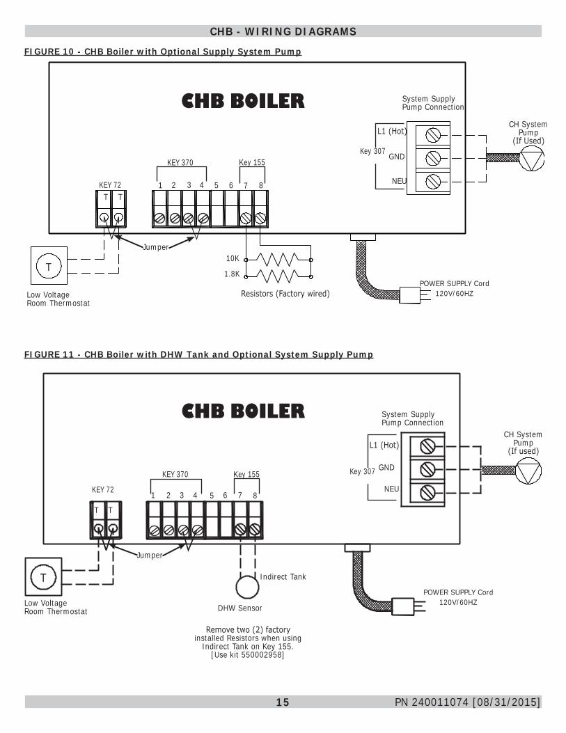
FIGURE 10 - CHB Boiler with Optional Supply System Pump
CHB - WIRING DIAGRAMS
FIGURE 11 - CHB Boiler with DHW Tank and Optional System Supply Pump
POWER SUPPLY Cord 120V/60HZ
CHB BOILERL1 (Hot)
2 43 5 6 8
KEY 370
KEY 72T
10K
1.8KT
Key 155GND
NEU1 7T
CHB BOILER
2 43 65 7 8
KEY 370
KEY 72
T T
T
Key 155
CH System Pump
(If used)
DHW SensorLow Voltage Room Thermostat
Jumper
1
Indirect Tank
Remove two (2) factory installed Resistors when using
Indirect Tank on Key 155.[Use kit 550002958]
System Supply Pump Connection
CH System Pump
(If Used)
Resistors (Factory wired)Low Voltage Room Thermostat
Jumper
Key 307
POWER SUPPLY Cord 120V/60HZ
L1 (Hot)
GND
NEU
System Supply Pump Connection
Key 307
16 PN 240011074 [08/31/2015]
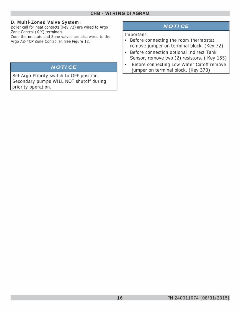
D. Multi-Zoned Valve System:Boiler call for heat contacts (key 72) are wired to Argo Zone Control (X-X) terminals. Zone thermostats and Zone valves are also wired to the Argo AZ-4CP Zone Controller. See Figure 12.
CHB - WIRING DIAGRAM
NOTICE
Set Argo Priority switch to OFF position. Secondary pumps WILL NOT shutoff during priority operation.
NOTICE
Important:• Before connecting the room thermostat,
remove jumper on terminal block. (Key 72)• Before connection optional Indirect Tank
Sensor, remove two (2) resistors. ( Key 155)• Before connecting Low Water Cutoff remove
jumper on terminal block. (Key 370)
17 PN 240011074 [08/31/2015]
CHB - WIRING DIAGRAMFIGURE 12 - CHB - Boiler Zoned System with Multiple ZONE VALVES with and without Indirect Tank
CHB BOILER
CHB BOILER
Argo AZ- 4CP
Low Volt Room Thermostats
VALVE VALVE VALVE VALVEZone Valve(S) Nec Class 2 Low Volt
Key 155KEY 370
10K1.8K
LN
POWER SUPPLY PLUG 120V/60HZ
JUMPER
Factory Supplied Resistors
Key 72
Key 72
KEY 370 Key 155
GND
NEU
POWER SUPPLY PLUG 120V/60HZINDIRECT TANK
DHW SENSOR
JUMPER
TO ARGO X-XTERMINALS
WITH INDIRECT TANK
CH SYSTEM PUMP
(If Used)
Priority Switch(NOT USED)
OFF
External System
Supply PumpConnection
External System
Supply PumpConnection
L1 (Hot)
L1 (Hot)
CH SYSTEM PUMP
(If Used)
WITH INDIRECT TANK
WITHOUT INDIRECT TANK
NEU
Key 307
GNDKey 307
18 PN 240011074 [08/31/2015]
CHB - WIRING DIAGRAM
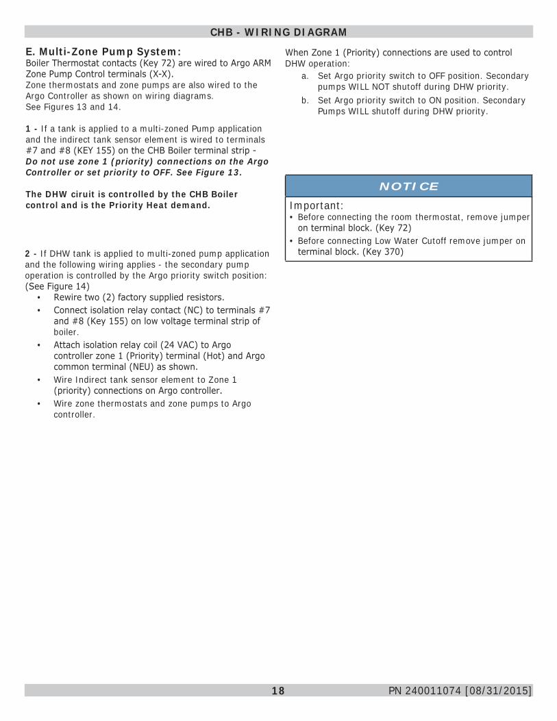
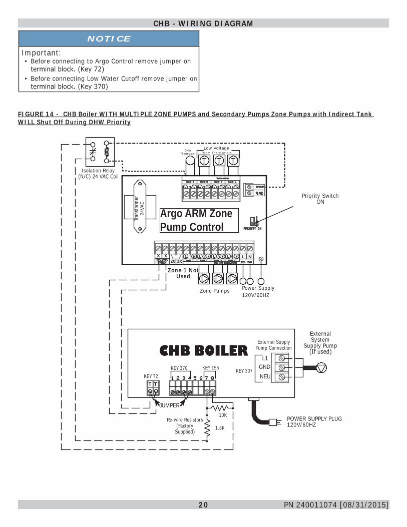
E. Multi-Zone Pump System:Boiler Thermostat contacts (Key 72) are wired to Argo ARM Zone Pump Control terminals (X-X). Zone thermostats and zone pumps are also wired to the Argo Controller as shown on wiring diagrams. See Figures 13 and 14.
1 - If a tank is applied to a multi-zoned Pump application and the indirect tank sensor element is wired to terminals #7 and #8 (KEY 155) on the CHB Boiler terminal strip - Do not use zone 1 (priority) connections on the Argo Controller or set priority to OFF. See Figure 13.
The DHW ciruit is controlled by the CHB Boiler control and is the Priority Heat demand.
2 - If DHW tank is applied to multi-zoned pump application and the following wiring applies - the secondary pump operation is controlled by the Argo priority switch position: (See Figure 14)
• Rewire two (2) factory supplied resistors.• Connect isolation relay contact (NC) to terminals #7
and #8 (Key 155) on low voltage terminal strip of boiler.
• Attach isolation relay coil (24 VAC) to Argo controller zone 1 (Priority) terminal (Hot) and Argo common terminal (NEU) as shown.
• Wire Indirect tank sensor element to Zone 1 (priority) connections on Argo controller.
• Wire zone thermostats and zone pumps to Argo controller.
When Zone 1 (Priority) connections are used to control DHW operation:
a. Set Argo priority switch to OFF position. Secondary pumps WILL NOT shutoff during DHW priority.
b. Set Argo priority switch to ON position. Secondary Pumps WILL shutoff during DHW priority.
NOTICE
Important:• Before connecting the room thermostat, remove jumper
on terminal block. (Key 72)• Before connecting Low Water Cutoff remove jumper on
terminal block. (Key 370)

19 PN 240011074 [08/31/2015]
CHB - WIRING DIAGRAM
Low VoltRoom Thermostats
CHB BOILER
CHB BOILER
Priority Switch(NOT USED)
OFF
T T
G
G G High Voltage Power Supply120V/60Hz
KEY 72KEY 370 KEY 155
External System
Supply Pump(If used)L1
NEU
GND
External Supply Pump Connection
10K1.8KFactory Supplied
Resistors
JUMPER
JUMPER
POWER SUPPLY PLUG 120V/60HZ
POWER SUPPLY PLUG 120V/60HZ
INDIRECT TANK DHW SENSOR
KEY 72KEY 370 KEY 155
External Supply Pump Connection
L1
NEU
GND
External System Supply Pump
(If used)
WITH DHW INDIRECT TANK
TO ARGO X-X TERMINALS ARM CONTROL
Argo ARM Zone Pump Control
Tran
sform
er
24VA
C
KEY 307
KEY 307
FIGURE 13 - CHB Boiler WITH MULTIPLE ZONE PUMPS With and Without Indirect Tank (DHW) Local Interface
Zone 1 Not Used
Zone 1 Not Used
20 PN 240011074 [08/31/2015]
CHB - WIRING DIAGRAM
FIGURE 14 - CHB Boiler WITH MULTIPLE ZONE PUMPS and Secondary Pumps Zone Pumps with Indirect Tank WILL Shut Off During DHW Priority
POWER SUPPLY PLUG 120V/60HZ
Priority SwitchON
Power Supply 120V/60HZ
CHB BOILER
Tran
sform
er
24VA
C
Argo ARM Zone Pump Control
Isolation Relay (N/C) 24 VAC Coil
DHW Thermostat
Low Voltage Room Thermostats
Zone Pumps
External Supply Pump Connection
External System
Supply Pump(If used)
L1
NEUGND
10K
1.8KRe-wire Resistors
(Factory Supplied)
JUMPER
KEY 72KEY 370 KEY 155 KEY 307
NOTICE
Important:• Before connecting to Argo Control remove jumper on
terminal block. (Key 72)• Before connecting Low Water Cutoff remove jumper on
terminal block. (Key 370)
Zone 1 Not Used
21 PN 240011074 [08/31/2015]
CCB - HYDRONIC PIPING
NOTICEArrange piping to prevent water dripping onto boiler.
A. Piping installation, materials, and joining methods shall conform to requirements of authority having jurisdiction or in absence of such requirements:
• USA - National Fuel Gas Code, ANSI Z223.1/NFPA 54• Canada - Natural Gas and Propane Installation Code,
CAN/CSA B149.1B. Manufacturer requires all domestic hot water (DHW) installations use an anti-scald valve. Local codes may require additional equipment (expansion tank, relief valves, etc.) select and size equipment to suit installation and meet code requirements.
Quick Reference Chart - CCB BoilerCCB - Hydronic Piping Description Page
ANTI-SCALD WARNING AND PIPING RECOMMENDATION 22
Single Boiler, Series Loop, Single Zone, No External Circulator (fig. 15) 23
Series Loop Zoned System WITH ZONE VALVES (fig. 16) 24
Single Boiler Primary/Secondary Series Loop Zoned System WITH ZONE VALVES (fig. 17) 25
Single Boiler Series Loop Zoned WITH ZONE PUMPS (fig. 18) 26
Single Boiler Primary/Secondary Series Loop Zoned WITH ZONE PUMPS (fig. 19) 27
Single Boiler Primary/Secondary Series Loop PUMPING (fig. 20) 28
CCB - Wiring Description Page
Boiler with Indirect DHW Storage Tank and Optional Supply System Pump (fig. 21) 29
Boiler with Multiple Zone Valves (fig. 22) 30
Boiler with Multiple Zone Pumps WITHOUT DHW Interface (fig. 23) 32
Boiler with Multiple Zone Pumps with DHW Interface (fig. 24) 33
22 PN 240011074 [05/30/2015]
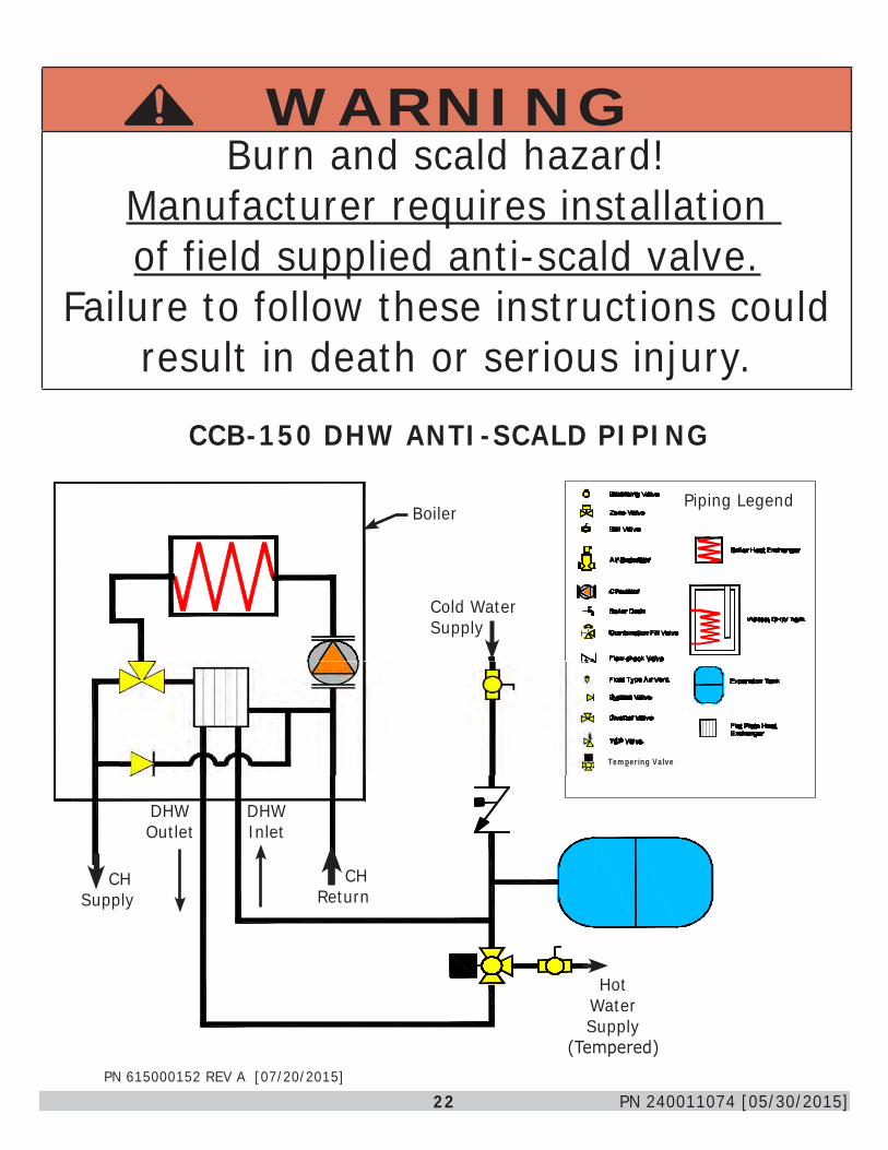
WARNINGBurn and scald hazard!
Manufacturer requires installation of field supplied anti-scald valve.
Failure to follow these instructions could result in death or serious injury.
!
PN 615000152 REV A [07/20/2015]
CCB-150 DHW ANTI-SCALD PIPING
Boiler
Cold Water Supply
Piping Legend
CH Return
HotWater Supply
(Tempered)
CH Supply
DHW Outlet
DHW Inlet
Tempering Valve
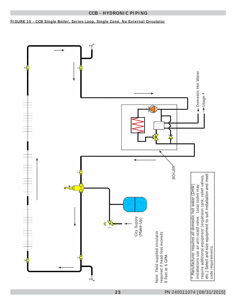
23 PN 240011074 [08/31/2015]
CCB - HYDRONIC PIPING
FIGURE 15 - CCB Single Boiler, Series Loop, Single Zone, No External Circulator
Dom
estic
Hot
Wat
er
BOIL
ER
City
Sup
ply
(Mak
e-U
p)
Usa
ge
Note
: Fi
eld
supp
lied
circ
ulat
or
requ
ired
if he
ad-lo
ss e
xcee
ds
8 Fe
et a
t 6 G
PM.
*
* M
anuf
actu
rer
requ
ires
all d
omes
tic h
ot w
ater
(D
HW)
inst
alla
tions
use
an
anti-
scal
d va
lve.
Loc
al c
odes
may
re
quire
add
ition
al e
quip
men
t (ex
pans
ion
tank
, rel
ief v
alve
s,
etc.
) Se
lect
and
siz
e eq
uipm
ent t
o su
it in
stal
latio
n an
d m
eet
code
req
uire
men
ts.

24 PN 240011074 [08/31/2015]
FIGURE 16 - CCB Series Loop Zoned System WITH ZONE VALVES
CCB - HYDRONIC PIPING
Dom
estic
Hot
Wat
er
BOIL
ER
City
Sup
ply
(Mak
e-U
p)
Usa
ge
CH/S
yste
m
Pum
p
*
* M
anuf
actu
rer
requ
ires
all d
omes
tic h
ot w
ater
(D
HW)
inst
alla
tions
use
an
anti-
scal
d va
lve.
Loc
al c
odes
may
re
quire
add
ition
al e
quip
men
t (ex
pans
ion
tank
, rel
ief v
alve
s,
etc.
) Se
lect
and
siz
e eq
uipm
ent t
o su
it in
stal
latio
n an
d m
eet
code
req
uire
men
ts.
25 PN 240011074 [08/31/2015]
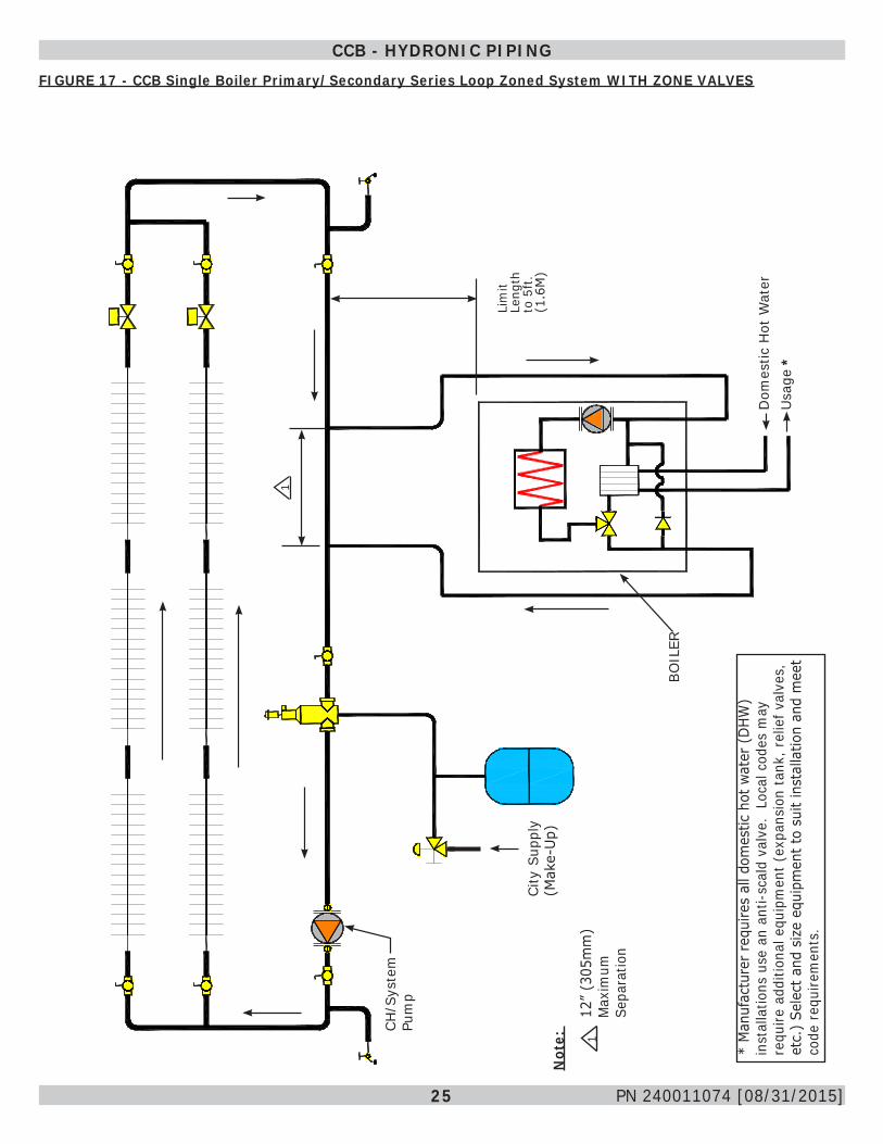
CCB - HYDRONIC PIPINGFIGURE 17 - CCB Single Boiler Primary/Secondary Series Loop Zoned System WITH ZONE VALVES
Dom
estic
Hot
Wat
er
BOIL
ER
City
Sup
ply
(Mak
e-U
p)
Lim
it Le
ngth
to
5ft
. (1
.6M
)
1
Usa
ge
CH/S
yste
m
Pum
p
Not
e:
112
” (3
05m
m)
Max
imum
Se
para
tion
* M
anuf
actu
rer
requ
ires
all d
omes
tic h
ot w
ater
(D
HW)
inst
alla
tions
use
an
anti-
scal
d va
lve.
Loc
al c
odes
may
re
quire
add
ition
al e
quip
men
t (ex
pans
ion
tank
, rel
ief v
alve
s,
etc.
) Se
lect
and
siz
e eq
uipm
ent t
o su
it in
stal
latio
n an
d m
eet
code
req
uire
men
ts.
*
26 PN 240011074 [08/31/2015]
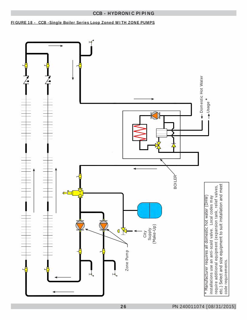
FIGURE 18 - CCB -Single Boiler Series Loop Zoned WITH ZONE PUMPS
CCB - HYDRONIC PIPING
Dom
estic
Hot
Wat
er
BOIL
ER
City
Su
pply
(M
ake-
Up)
Usa
ge
Zone
Pum
p
**
Man
ufac
ture
r re
quire
s al
l dom
estic
hot
wat
er (
DHW
) in
stal
latio
ns u
se a
n an
ti-sc
ald
valv
e. L
ocal
cod
es m
ay
requ
ire a
dditi
onal
equ
ipm
ent (
expa
nsio
n ta
nk, r
elie
f val
ves,
et
c.)
Sele
ct a
nd s
ize
equi
pmen
t to
suit
inst
alla
tion
and
mee
t co
de r
equi
rem
ents
.
27 PN 240011074 [08/31/2015]
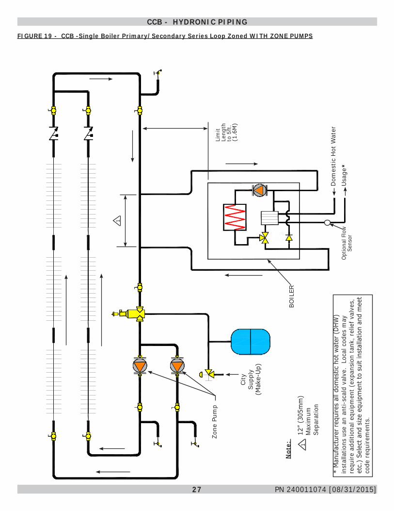
FIGURE 19 - CCB -Single Boiler Primary/Secondary Series Loop Zoned WITH ZONE PUMPS
CCB - HYDRONIC PIPING
Dom
estic
Hot
Wat
er
BOIL
ER
City
Su
pply
(M
ake-
Up)
Lim
it Le
ngth
to
5ft
. (1
.6M
)
1
Usa
ge
Zone
Pum
p
Not
e:
112
” (3
05m
m)
Max
imum
Se
para
tion
Optio
nal F
low
Se
nsor
**
Man
ufac
ture
r re
quire
s al
l dom
estic
hot
wat
er (
DHW
) in
stal
latio
ns u
se a
n an
ti-sc
ald
valv
e. L
ocal
cod
es m
ay
requ
ire a
dditi
onal
equ
ipm
ent (
expa
nsio
n ta
nk, r
elie
f val
ves,
et
c.)
Sele
ct a
nd s
ize
equi
pmen
t to
suit
inst
alla
tion
and
mee
t co
de r
equi
rem
ents
.
28 PN 240011074 [08/31/2015]
CCB - HYDRONIC PIPING
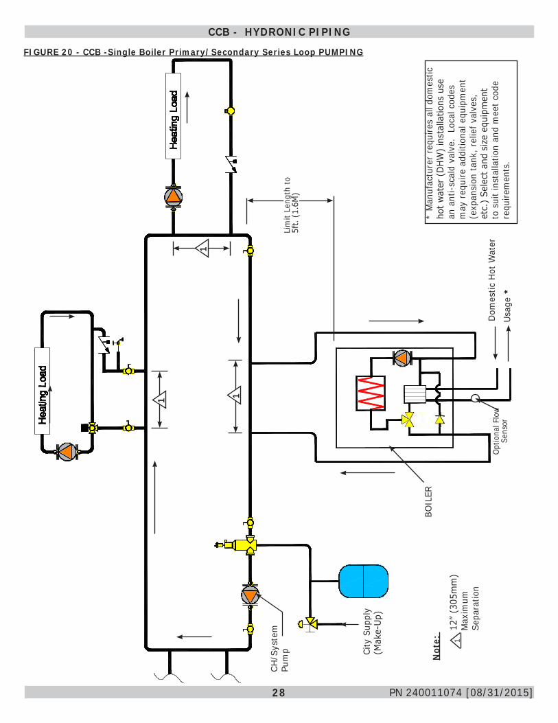
FIGURE 20 - CCB -Single Boiler Primary/Secondary Series Loop PUMPING
Dom
estic
Hot
Wat
er
BOIL
ER
City
Sup
ply
(Mak
e-Up
)
Lim
it Le
ngth
to
5ft.
(1.
6M)
Usag
e
CH/S
yste
m
Pum
p
Not
e:
112
” (3
05m
m)
Max
imum
Se
para
tion
Optio
nal F
low
Se
nsor
*
1
1
* M
anuf
actu
rer
requ
ires
all d
omes
tic
hot w
ater
(D
HW)
inst
alla
tions
use
an
ant
i-sca
ld v
alve
. Lo
cal c
odes
m
ay r
equi
re a
dditi
onal
equ
ipm
ent
(exp
ansi
on ta
nk, r
elie
f val
ves,
et
c.)
Sele
ct a
nd s
ize
equi
pmen
t to
sui
t ins
talla
tion
and
mee
t cod
e re
quire
men
ts.
1
29 PN 240011074 [08/31/2015]
CCB BOILER - WIRING DIAGRAMS
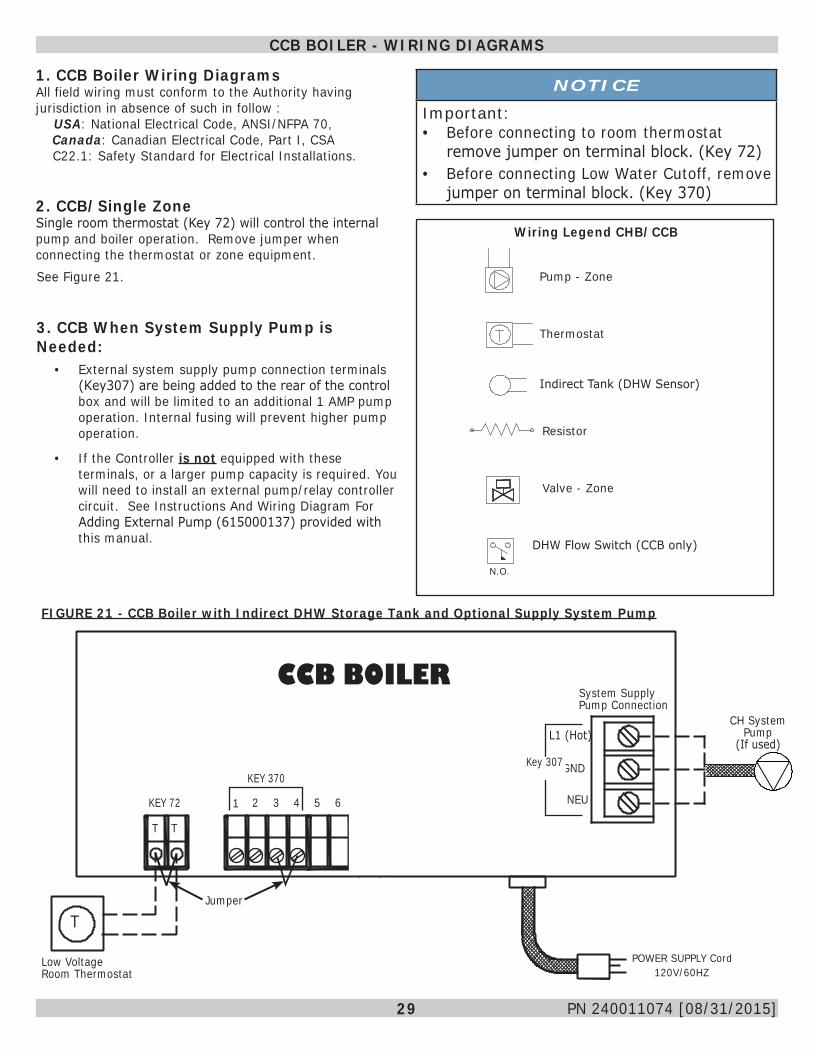
1. CCB Boiler Wiring DiagramsAll field wiring must conform to the Authority having jurisdiction in absence of such in follow :
USA: National Electrical Code, ANSI/NFPA 70, Canada: Canadian Electrical Code, Part I, CSA C22.1: Safety Standard for Electrical Installations. 2. CCB/Single Zone Single room thermostat (Key 72) will control the internal pump and boiler operation. Remove jumper when connecting the thermostat or zone equipment.
FIGURE 21 - CCB Boiler with Indirect DHW Storage Tank and Optional Supply System Pump
3. CCB When System Supply Pump is Needed:
• External system supply pump connection terminals (Key307) are being added to the rear of the control box and will be limited to an additional 1 AMP pump operation. Internal fusing will prevent higher pump operation.
• If the Controller is not equipped with these terminals, or a larger pump capacity is required. You will need to install an external pump/relay controller circuit. See Instructions And Wiring Diagram For Adding External Pump (615000137) provided with this manual.
NOTICE
Important:• Before connecting to room thermostat
remove jumper on terminal block. (Key 72)• Before connecting Low Water Cutoff, remove
jumper on terminal block. (Key 370)
See Figure 21.
Wiring Legend CHB/CCB
Pump - Zone
Thermostat
Indirect Tank (DHW Sensor)
Resistor
Valve - Zone
DHW Flow Switch (CCB only)
N.O.
CCB BOILER
2 43 65 7 8
KEY 370
KEY 72
T T
T
Low Voltage Room Thermostat
Jumper
1
CH System Pump
(If used)
POWER SUPPLY Cord 120V/60HZ
L1 (Hot)
GND
NEU
System Supply Pump Connection
Key 307
30 PN 240011074 [08/31/2015]
CCB BOILER - WIRING DIAGRAMS
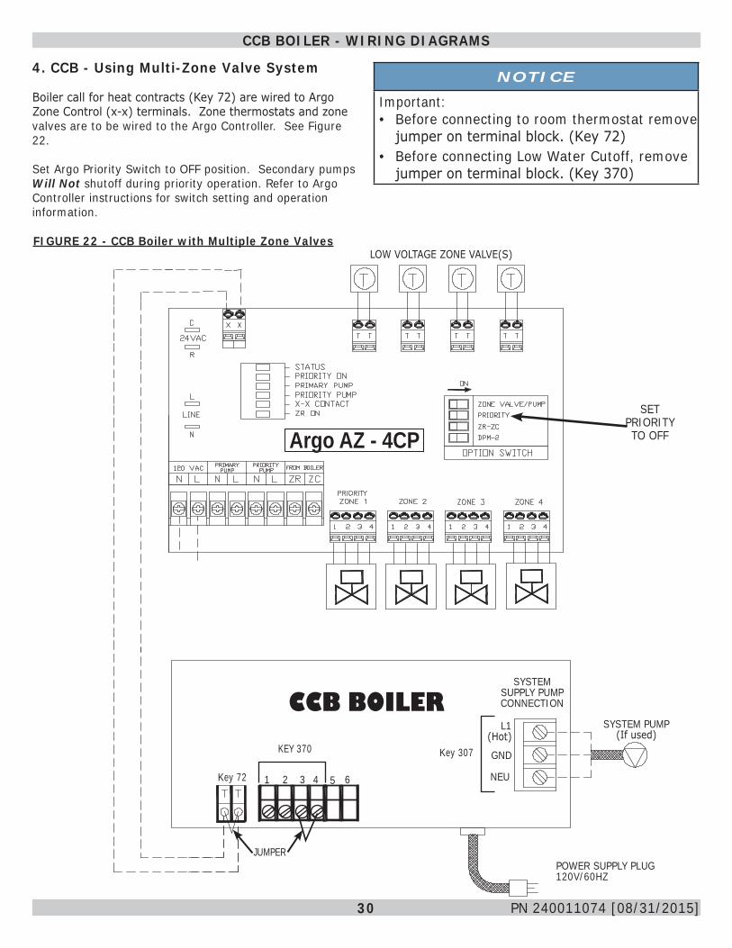
4. CCB - Using Multi-Zone Valve System
Boiler call for heat contracts (Key 72) are wired to Argo Zone Control (x-x) terminals. Zone thermostats and zone valves are to be wired to the Argo Controller. See Figure 22.
Set Argo Priority Switch to OFF position. Secondary pumps Will Not shutoff during priority operation. Refer to Argo Controller instructions for switch setting and operation information.
NOTICE
Important:• Before connecting to room thermostat remove
jumper on terminal block. (Key 72)• Before connecting Low Water Cutoff, remove
jumper on terminal block. (Key 370)
FIGURE 22 - CCB Boiler with Multiple Zone Valves
Argo AZ - 4CPSET
PRIORITY TO OFF
LOW VOLTAGE ZONE VALVE(S)
Key 307
JUMPER
Key 72
POWER SUPPLY PLUG 120V/60HZ
CCB BOILERL1
(Hot)
NEU
GND
2 43 5 7 8
KEY 370
1
SYSTEM PUMP (If used)
SYSTEM SUPPLY PUMP CONNECTION
6
31 PN 240011074 [08/31/2015]
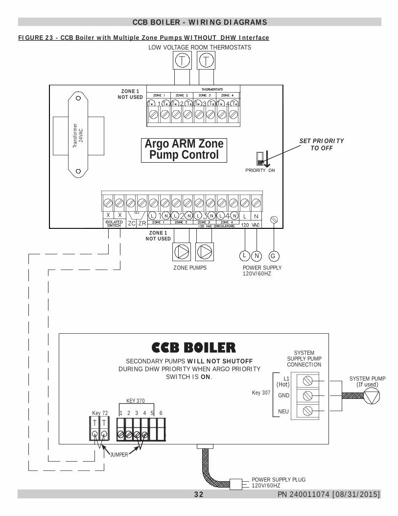
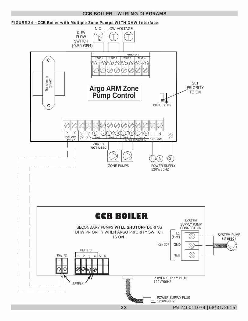
5. CCB Using Multi-Zone Pump System
Wiring of Argo Control may include Priority Zone Control.
Boiler thermostat contacts (Key 72) are wired to Argo ARM Zone Pump Control terminals (x-x). Use Argo ARM Zone Pump Controller as shown in Figure 23.
1. When priority zone control is not desired. Wire zone pumps and thermostats as shown in Figure 23. Do Not use Zone 1 (Priority) connections on Argo Controller or set Priority to off. Secondary pumps Will Not shutoff during DHW priority.
2. When priority zone control is desired, wire zone pumps and thermostats as shown in Figure 24. Wire priority flow controller (not supplied ) across Zone 1 (Priority) thermostat connections. Zone 1 pump terminals are not used, unless a Primary Pump if being applied. Set the Argo Priority switch to ON, secondary pumps Will shutoff during DHW priority.
NOTICE
Important:• Before connecting to room thermostat
remove jumper on terminal block. (Key 72)• Before connecting Low Water Cutoff, remove
jumper on terminal block. (Key 370)
CCB BOILER - WIRING DIAGRAMS
32 PN 240011074 [08/31/2015]
FIGURE 23 - CCB Boiler with Multiple Zone Pumps WITHOUT DHW Interface
Argo ARM Zone Pump Control
JUMPER
Key 307
POWER SUPPLY PLUG 120V/60HZ
CCB BOILER
SYSTEM PUMP (If used)
SYSTEM SUPPLY PUMP CONNECTION
POWER SUPPLY 120V/60HZ
Key 72
SECONDARY PUMPS WILL NOT SHUTOFF DURING DHW PRIORITY WHEN ARGO PRIORITY
SWITCH IS ON.
SET PRIORITY TO OFF
ZONE PUMPS
L N G
ZONE 1 NOT USED
LOW VOLTAGE ROOM THERMOSTATS
L1 (Hot)
NEU
GND
Tran
sform
er
24VA
C
ZONE 1 NOT USED
CCB BOILER - WIRING DIAGRAMS
2 43 5 7 81
KEY 370
66
33 PN 240011074 [08/31/2015]
FIGURE 24 - CCB Boiler with Multiple Zone Pumps WITH DHW Interface
CCB BOILER - WIRING DIAGRAMS
N.O.
Argo ARM Zone Pump Control
POWER SUPPLY 120V/60HZ
SET PRIORITY
TO ON
ZONE PUMPS
L N G
ZONE 1 NOT USED
DHW FLOW
SWITCH
LOW VOLTAGE
Key 307
POWER SUPPLY PLUG 120V/60HZ
CCB BOILER
SYSTEM PUMP (If used)
SYSTEM SUPPLY PUMP CONNECTION
Key 72
JUMPERPOWER SUPPLY PLUG 120V/60HZ
2 43 5 7 8KEY 370
1
L1 (Hot)
NEU
GND
SECONDARY PUMPS WILL SHUTOFF DURING DHW PRIORITY WHEN ARGO PRIORITY SWITCH
IS ON.
6
Tran
sform
er
24VA
C(0.50 GPM)
34 PN 240011074 [08/31/2015]
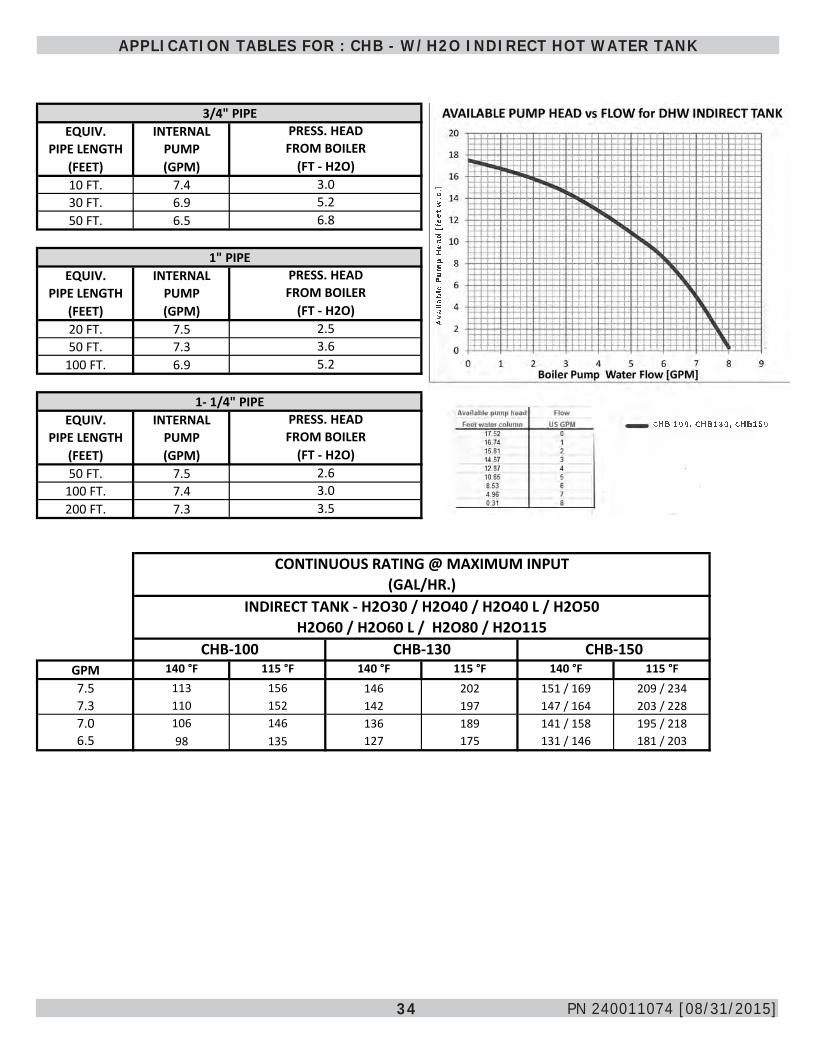
APPLICATION TABLES FOR : CHB - W/H2O INDIRECT HOT WATER TANK
CHB 100, CHB130, CHB150
Ava
ilab
le P
um
p H
ead
[fe
et w
.c.]
3/4" PIPE EQUIV. INTERNAL
PIPE LENGTH PUMP(FEET) (GPM)10 FT. 7.430 FT. 6.950 FT. 6.5
1" PIPE EQUIV. INTERNAL
PIPE LENGTH PUMP(FEET) (GPM)20 FT. 7.550 FT. 7.3
100 FT. 6.9
1- 1/4" PIPE EQUIV. INTERNAL
PIPE LENGTH PUMP(FEET) (GPM)50 FT. 7.5
100 FT. 7.4200 FT. 7.3
CONTINUOUS RATING @ MAXIMUM INPUT(GAL/HR.)
INDIRECT TANK - H2O30 / H2O40 / H2O40 L / H2O50H2O60 / H2O60 L / H2O80 / H2O115
GPM 140 °F 115 °F 140 °F 115 °F 140 °F 115 °F7.5 113 156 146 202 151 / 169 209 / 2347.3 110 152 142 197 147 / 164 203 / 2287.0 106 146 136 189 141 / 158 195 / 2186.5 98 135 127 175 131 / 146 181 / 203
CHB-100 CHB-130 CHB-150
2.63.03.5
FROM BOILER
FROM BOILER
FROM BOILER
(FT - H2O)2.53.65.2
PRESS. HEAD
(FT - H2O)
PRESS. HEAD
PRESS. HEAD
(FT - H2O)3.05.26.8

35 PN 240011074 [08/31/2015]
APPLICATION TABLES FOR : CHB - W/H2O INDIRECT HOT WATER TANK
Tabl
e B
ased
on
BO
ILER
OU
TPU
T (B
TUH
/HR
)M
AX.
BO
ILER
OU
TPU
T (B
TUH
/HR
)M
AX.
BO
ILER
OU
TPU
T (B
TUH
/HR
)M
AX.
Boi
ler F
low
Rat
e =
7.5
GPM
50,0
0060
,000
80,0
0085
,000
50,0
0060
,000
80,0
0010
0,00
011
0,00
050
,000
60,0
0080
,000
100,
000
120,
000
128,
000
140
F94
107
134
140
9410
713
416
017
394
107
134
160
170
170
115
F11
913
817
418
311
913
817
421
122
911
913
817
421
122
522
514
0 F
6780
107
113
6780
107
133
146
6780
107
133
143
143
115
F92
111
147
156
9211
114
718
420
292
111
147
184
198
198
H2O
40 /
H2O
40L
140
F10
311
614
314
910
311
614
316
918
210
311
614
316
918
7 / 1
8018
7 / 1
8011
5 F
128
147
183
192
128
147
183
220
238
128
147
183
220
245
/ 235
245
/ 235
140
F67
8010
711
367
8010
713
314
667
8010
713
315
1 / 1
4415
1 / 1
4411
5 F
9211
114
715
692
111
147
184
202
9211
114
718
420
9 / 1
9920
9 / 1
99
H2O
5014
0 F
112
125
152
158
112
125
152
178
191
112
125
152
178
187
190
115
F13
715
619
220
113
715
619
222
924
713
715
619
222
924
825
214
0 F
6780
107
113
6780
107
133
146
6780
107
133
160
163
115
F92
111
147
156
9211
114
718
420
292
111
147
184
221
225
140
F12
113
416
116
712
113
416
118
720
012
113
416
118
719
6 / 1
8720
5 / 1
8711
5 F
146
165
201
210
146
165
201
238
256
146
165
201
238
257
/ 245
270
/ 245
140
F67
8010
711
367
8010
713
314
667
8010
713
316
0 / 1
5116
9 / 1
5111
5 F
9211
114
715
692
111
147
184
202
9211
114
718
422
1 / 2
0923
4 / 2
09
H2O
8014
0 F
139
152
179
185
139
152
179
205
218
139
152
179
205
187
190
115
F16
418
321
922
816
418
321
925
627
416
418
321
925
624
825
214
0 F
6780
107
113
6780
107
133
146
6780
107
133
160
163
115
F92
111
147
156
9211
114
718
420
292
111
147
184
221
225
H2O
115
140
F17
018
321
021
617
018
321
023
624
917
018
321
023
619
620
511
5 F
195
214
250
259
195
214
250
287
305
195
214
250
287
257
270
140
F67
8010
711
367
8010
713
314
667
8010
713
316
016
911
5 F
9211
114
715
692
111
147
184
202
9211
114
718
422
123
4N
OTE
S:
(GAL
/HR
)
CH
B-1
00 B
OIL
ER
(100
,000
BTU
H
MAX
IMU
M IN
PUT
RAT
E)
H2O
30
CH
B-1
30 B
OIL
ER
(130
,000
BTU
H M
AXIM
UM
IN
PUT
RAT
E)
1st H
OU
R R
ATIN
G(G
AL/H
R)
CO
NTI
NU
OU
SR
ATIN
G (G
AL/H
R)
1st H
OU
R R
ATIN
G
CH
B-1
50 B
OIL
ER
(150
,000
BTU
H M
AXIM
UM
INPU
T R
ATE)
1st H
OU
R R
ATIN
G(G
AL/H
R)
CO
NTI
NU
OU
SR
ATIN
G (G
AL/H
R)
CO
NTI
NU
OU
S
1st H
OU
R R
ATIN
G(G
AL/H
R)
RAT
ING
(GAL
/HR
)
1st H
OU
R R
ATIN
G(G
AL/H
R)
CO
NTI
NU
OU
SR
ATIN
G (G
AL/H
R)
H2O
60 /
H2O
60L
1st H
OU
R R
ATIN
G(G
AL/H
R)
CO
NTI
NU
OU
SR
ATIN
G (G
AL/H
R)
180
°F B
oile
r Sup
ply
Wat
er T
empe
ratu
reAH
RI R
atin
g C
ondi
tions
- 50
°F In
let W
ater
CO
NTI
NU
OU
SR
ATIN
G (G
AL/H
R)
36 PN 240011074 [08/31/2015]
SENSORS - OPTIONAL EQUIPMENT
Optional Equipment
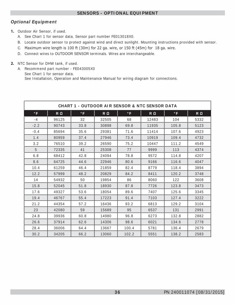
1. Outdoor Air Sensor, if used.A. See Chart 1 for sensor data. Sensor part number FE013018X0.B. Locate outdoor sensor to protect against wind and direct sunlight. Mounting instructions provided with sensor.C. Maximum wire length is 100 ft (30m) for 22 ga. wire, or 150 ft (45m) for 18 ga. wire.D. Connect wires to OUTDOOR SENSOR terminals. Wires are interchangeable.
2. NTC Sensor for DHW tank, if used.A. Recommend part number - FE043005X0
See Chart 1 for sensor data. See Installation, Operation and Maintenance Manual for wiring diagram for connections.
CHART 1 - OUTDOOR AIR SENSOR & NTC SENSOR DATA
°F R Ω °F R Ω °F R Ω °F R Ω-4 96125 32 32505 68 12483 104 5332
-2.2 90743 33.8 30898 69.8 11935 105.8 5123-0.4 85694 35.6 29381 71.6 11414 107.6 49231.4 80959 37.4 27946 73.4 10919 109.4 47323.2 76510 39.2 26590 75.2 10447 111.2 45495 72335 41 25308 77 9999 113 4374
6.8 68412 42.8 24094 78.8 9572 114.8 42078.6 64725 44.6 22946 80.6 9166 116.6 404710.4 61259 46.4 21859 82.4 8779 118.4 389412.2 57999 48.2 20829 84.2 8411 120.2 374814 54932 50 19854 86 8060 122 3608
15.8 52045 51.8 18930 87.8 7726 123.8 347317.6 49327 53.6 18054 89.6 7407 125.6 334519.4 46767 55.4 17223 91.4 7103 127.4 322221.2 44354 57.2 16436 93.2 6813 129.2 310423 42080 59 15689 95 6537 131 2991
24.8 39936 60.8 14980 96.8 6273 132.8 288226.6 37914 62.6 14306 98.6 6021 134.6 277828.4 36006 64.4 13667 100.4 5781 136.4 267930.2 34205 66.2 13060 102.2 5551 138.2 2583
37 PN 240011074 [08/31/2015]
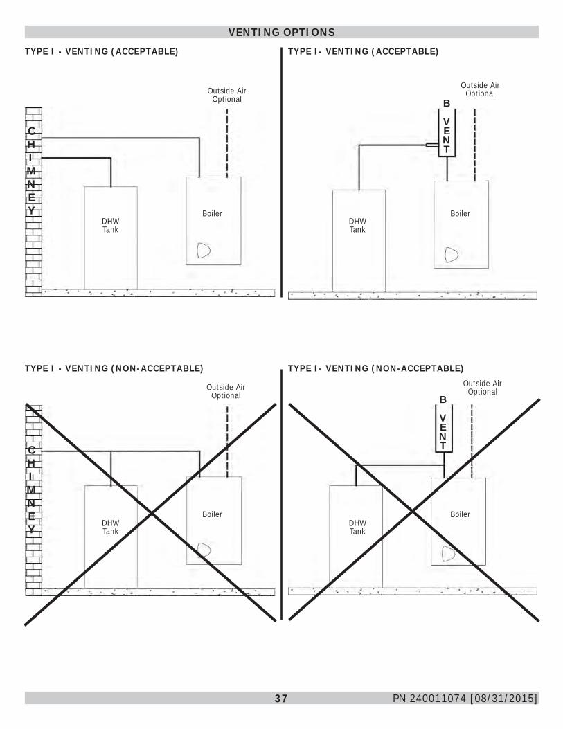
VENTING OPTIONSTYPE I - VENTING (ACCEPTABLE) TYPE I- VENTING (ACCEPTABLE)
TYPE I - VENTING (NON-ACCEPTABLE) TYPE I- VENTING (NON-ACCEPTABLE)
CHIMNEY
DHW Tank
Boiler
Outside Air Optional
DHW Tank
DHW Tank
DHW Tank
Boiler
Boiler
Boiler
Outside Air Optional
B
VENT
Outside Air Optional
Outside Air Optional
B
VENTC
HIMNEY
38 PN 240011074 [08/31/2015]
ADDENDUM - INSTRUCTIONS
Addendum - Instructions
Following Section Includes: Page #(s)
Domestic Hot Water Sensor Kit Instruction (240010745)..........................................39-42
Instructions And Wiring Diagram For Adding External Pump (615000137)...............43-44
Sealed Combustion Kit Instructions (37711601) - For Kit #5612601.........................45
Control Board Replacement Kit Instructions (615000134).........................................46-47
Retaining Clip Removal Caution (615000136)............................................................48-49
Altitude Affects on CHB-100, CHB-130, CHB-150 and CCB-150...................................50
LP Conversion Kit Instructions...................................................................................51-53
39
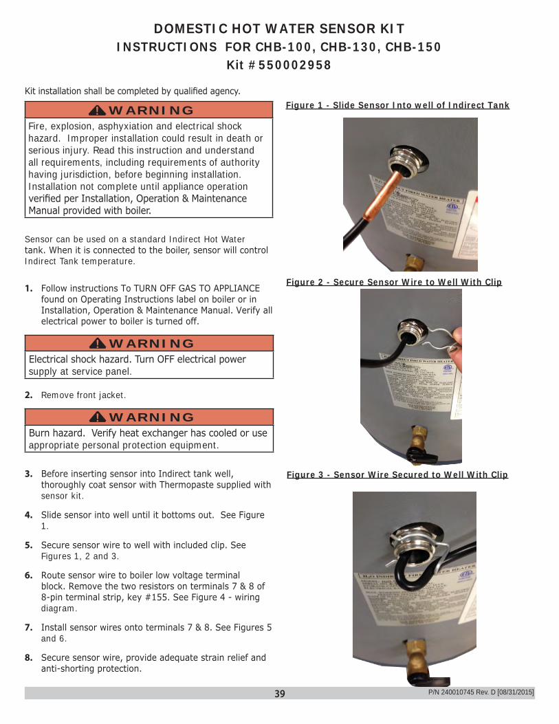
DOMESTIC HOT WATER SENSOR KITINSTRUCTIONS FOR CHB-100, CHB-130, CHB-150
Kit #550002958
WARNINGFire, explosion, asphyxiation and electrical shock hazard. Improper installation could result in death or serious injury. Read this instruction and understand all requirements, including requirements of authority having jurisdiction, before beginning installation. Installation not complete until appliance operation verified per Installation, Operation & Maintenance Manual provided with boiler.
!
Sensor can be used on a standard Indirect Hot Water tank. When it is connected to the boiler, sensor will control Indirect Tank temperature.
1. Follow instructions To TURN OFF GAS TO APPLIANCE found on Operating Instructions label on boiler or in Installation, Operation & Maintenance Manual. Verify all electrical power to boiler is turned off.
WARNINGElectrical shock hazard. Turn OFF electrical power supply at service panel.
!
2. Remove front jacket.
WARNINGBurn hazard. Verify heat exchanger has cooled or use appropriate personal protection equipment.
!
3. Before inserting sensor into Indirect tank well, thoroughly coat sensor with Thermopaste supplied with sensor kit.
4. Slide sensor into well until it bottoms out. See Figure 1.
5. Secure sensor wire to well with included clip. See Figures 1, 2 and 3.
6. Route sensor wire to boiler low voltage terminal block. Remove the two resistors on terminals 7 & 8 of 8-pin terminal strip, key #155. See Figure 4 - wiring diagram.
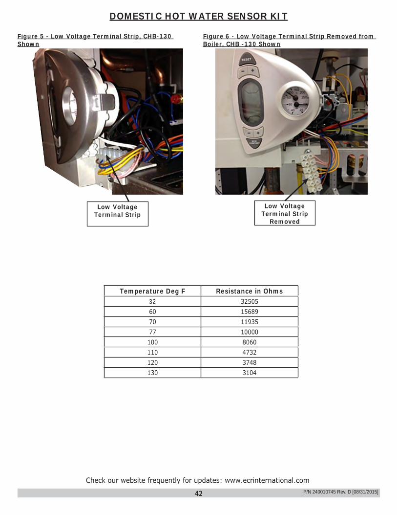
7. Install sensor wires onto terminals 7 & 8. See Figures 5 and 6.
8. Secure sensor wire, provide adequate strain relief and anti-shorting protection.
P/N 240010745 Rev. D [08/31/2015]
Figure 1 - Slide Sensor Into well of Indirect TankKit installation shall be completed by qualified agency.
Figure 2 - Secure Sensor Wire to Well With Clip
Figure 3 - Sensor Wire Secured to Well With Clip

40
9. Restore power to boiler. Boiler will automatically recognize the sensor.
10. See Installation, Operation & Maintenance Manual for adjusting DHW tank temperature and operation.
11. Resume operation using Installation, Operation & Maintenance Manual.
12. Verify proper operation by following START UP PROCEDURE in Installation, Operation & Maintenance Manual.
13. Install front cover.
DOMESTIC HOT WATER SENSOR KIT
DOMESTIC HOT WATER SENSOR KIT FOR CHB-100/ CHB-130/ CHB150
#550002958DESCRIPTION PART # QTYDHW Tank Sensor - 1Clip - 1Thermopaste - 1Instructions 240010745 1
P/N 240010745 Rev. D [08/31/2015]
41
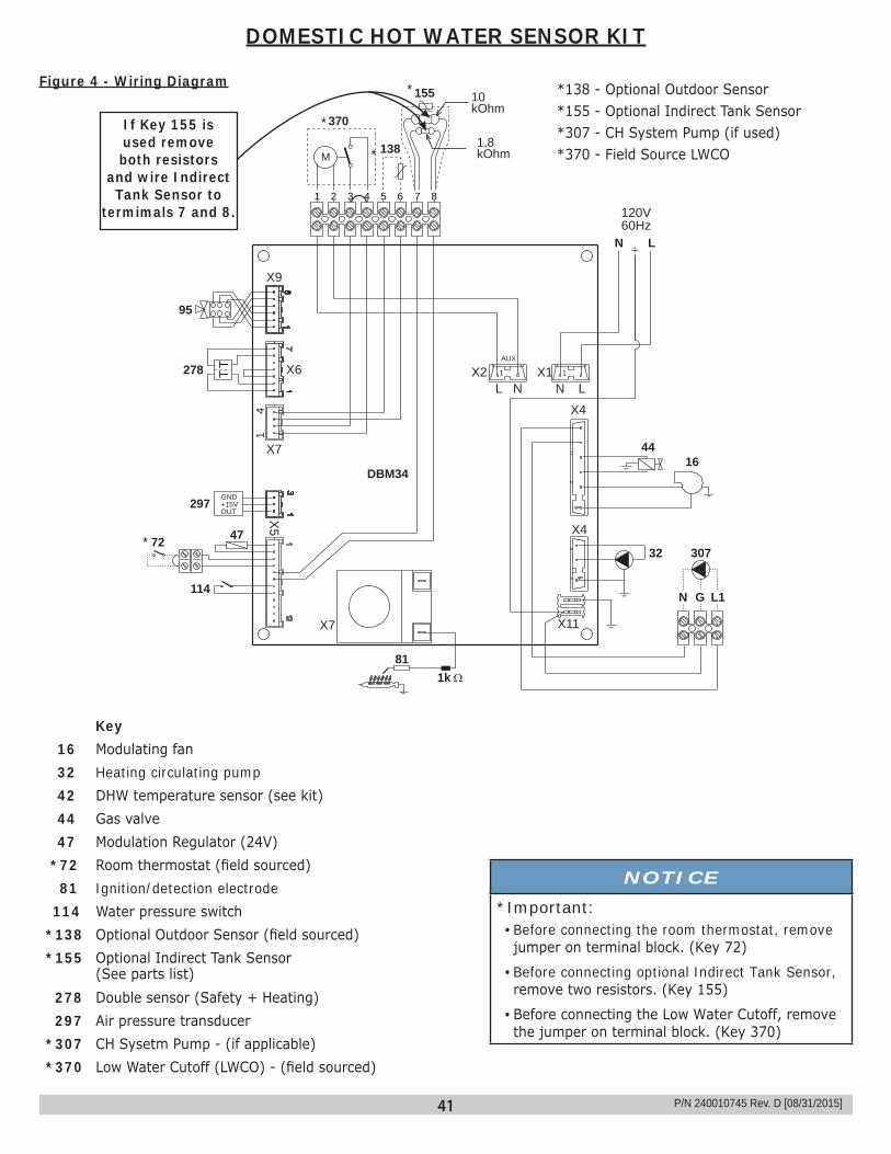
37 EN
1k81
32
95
278
1
4
120V60Hz
138
5 6 7 83 41 2
1644
N L
138
370
95
278 TT
297
47
114
GND+15VOUT
155
72
X1X2AUX
X4
X4
X11X7X
5
X7
X6
X9
L LN N1 1
DBM34
WIRING DIAGRAM
Key
16 Modulating fan32 Heating circulating pump42 DHW temperature sensor (see kit)44 Gas valve47 Modulation Regulator (24V)72 Room thermostat (field sourced)81 Ignition/detection electrode114 Water pressure switch138 External probe (not fitted)
155 Hot water tank temperature probe (field sourced)278 Double sensor (safety + Heating)297 Air pressure transducer307 Heating system second circulating pump (not supplied)370 Low Water Cutoff (LWCO) - (field sourced)
Important: Before connecting the room thermostat, remove the jumper on terminal block.
138 Optional Outdoor Sensor155 Optional Indirect Tank Sensor370 Field Source LWCO
307
10kOhm
1,8kOhmM
N G L1
*138 - Optional Outdoor Sensor*155 - Optional Indirect Tank Sensor*307 - CH System Pump (if used)*370 - Field Source LWCO
Key 16 Modulating fan 32 Heating circulating pump 42 DHW temperature sensor (see kit) 44 Gas valve 47 Modulation Regulator (24V)*72 Room thermostat (field sourced) 81 Ignition/detection electrode 114 Water pressure switch*138 Optional Outdoor Sensor (field sourced) *155 Optional Indirect Tank Sensor
(See parts list) 278 Double sensor (Safety + Heating) 297 Air pressure transducer*307 CH Sysetm Pump - (if applicable) *370 Low Water Cutoff (LWCO) - (field sourced)
*
*
*
NOTICE*Important: • Before connecting the room thermostat, remove jumper on terminal block. (Key 72)
• Before connecting optional Indirect Tank Sensor, remove two resistors. (Key 155)
• Before connecting the Low Water Cutoff, remove the jumper on terminal block. (Key 370)
*
Figure 4 - Wiring Diagram
If Key 155 is used remove both resistors
and wire Indirect Tank Sensor to
termimals 7 and 8.
DOMESTIC HOT WATER SENSOR KIT
P/N 240010745 Rev. D [08/31/2015]
42
DOMESTIC HOT WATER SENSOR KIT
Figure 5 - Low Voltage Terminal Strip, CHB-130 Shown
Figure 6 - Low Voltage Terminal Strip Removed from Boiler, CHB -130 Shown
Low Voltage Terminal Strip
Low Voltage Terminal Strip
Removed
Temperature Deg F Resistance in Ohms32 3250560 1568970 1193577 10000100 8060110 4732120 3748130 3104
Check our website frequently for updates: www.ecrinternational.comP/N 240010745 Rev. D [08/31/2015]
43
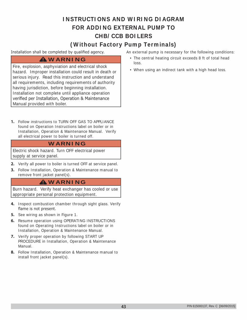
INSTRUCTIONS AND WIRING DIAGRAM FOR ADDING EXTERNAL PUMP TO
CHB/CCB BOILERS(Without Factory Pump Terminals)
P/N 615000137, Rev. C [06/09/2015]
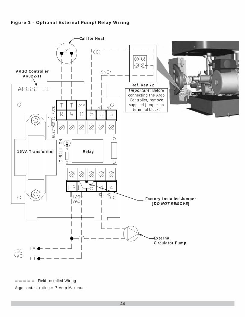
1. Follow instructions to TURN OFF GAS TO APPLIANCE found on Operation Instructions label on boiler or in Installation, Operation & Maintenance Manual. Verify all electrical power to boiler is turned off.
WARNINGElectric shock hazard. Turn OFF electrical power supply at service panel.
2. Verify all power to boiler is turned OFF at service panel.3. Follow Installation, Operation & Maintenance manual to
remove front jacket panel(s).
WARNINGBurn hazard. Verify heat exchanger has cooled or use appropriate personal protection equipment.
!
4. Inspect combustion chamber through sight glass. Verify flame is not present.
5. See wiring as shown in Figure 1.6. Resume operation using OPERATING INSTRUCTIONS
found on Operating Instructions label on boiler or in Installation, Operation & Maintenance Manual.
7. Verify proper operation by following START UP PROCEDURE in Installation, Operation & Maintenance Manual.
8. Follow Installation, Operation & Maintenance manual to install front jacket panel(s).
Installation shall be completed by qualified agency.
WARNINGFire, explosion, asphyxiation and electrical shock hazard. Improper installation could result in death or serious injury. Read this instruction and understand all requirements, including requirements of authority having jurisdiction, before beginning installation. Installation not complete until appliance operation verified per Installation, Operation & Maintenance Manual provided with boiler.
! An external pump is necessary for the following conditions:
• The central heating circuit exceeds 8 ft of total head loss.
• When using an indirect tank with a high head loss.
44
ARGO Controller AR822-II
Figure 1 - Optional External Pump/Relay Wiring
Factory Installed Jumper [DO NOT REMOVE]
Call for Heat
15VA Transformer Relay
External Circulator Pump
Ref. Key 72Important: Before connecting the Argo Controller, remove supplied jumper on
terminal block.
Field Installed Wiring
Argo contact rating = 7 Amp Maximum

45
Sealed Combustion Termination Kit # 5612601
Installation Instructions
WARNINGFire, explosion, asphyxiation and electrical shock hazard. Improper installation could result in death or serious injury. Read this instruction and understand all requirements, including requirements of authority having jurisdiction, before beginning installation. Installation not complete until appliance operation is verified per Installation, Operation & Maintenance Manual provided with boiler.
!
P/N 37711601 Rev. A [05/2015]
Kit installation shall be completed by qualified agency.
Horizontal (Category III) venting systems installation shall conform to the requirements of the authority having jurisdiction or, in the absence of such requirements:
• National Fuel Gas Code, ANSI Z223.1/NFPA 54,
and/or• Natural Gas and Propane Installation Code, CAN/CSA
B149.1
Figure 1 - Sealed Combustion Termination
Installation Instructions:1. Use supplied template to cut a hole through the wall.
Secure template to inside wall.
NOTICEIf installing through non-combustible wall, remove termination thimble. Make two (2) 3½" ±1" holes on center through the wall.
2. Install vent termination assembly to outside wall.3. Install PVC pipe from vent termination assembly to
boiler's air inlet.4. Assemble vent pipe following vent pipe manufacturer's
instructions.5. Install vent pipe through termination assembly and
extend 3" beyond the assembly.6. Install termination deflector using four (4) provided
screws.7. Install draw collar around vent pipe. Tighten nut and
screw until secured tightly.8. Secure termination tee according to vent pipe
manufacturer's instructions.
Termination Thimble
Termination Assembly
Termination Deflector
Draw Collar
#10-24 Hex Nut
3" Termination Tee (Purchased Separately)
Screw #10-24x1½" RH
4 Screws #10 x½ HX HD
(8" X 12") Template
3" Stainless Steel Vent Pipe (Purchased Separately)
3" PVC Pipe Air Intake(Purchased Separately)
Wall
To Boile
r
46
Kit installation shall be completed by qualified agency.
WARNINGFire, explosion, asphyxiation and electrical shock hazard. Improper installation could result in death or serious injury. Read this instruction and understand all requirements, including requirements of authority having jurisdiction, before beginning installation. Installation not complete until appliance operation verified per Installation, Operation & Maintenance Manual provided with boiler.
!
1. Follow instructions TO TURN OFF GAS TO APPLIANCE found on Operating Instructions label on boiler or in Installation, Operation & Maintenance Manual. Verify all electrical power to boiler is turned off.
WARNINGElectrical shock hazard. Turn OFF electrical power supply at service panel.
!
2. Remove front jacket casing per instructions found in Installation, Operation & Maintenance Manual.
WARNINGBurn hazard. Verify heat exchanger has cooled or use appropriate personal protection equipment.
!
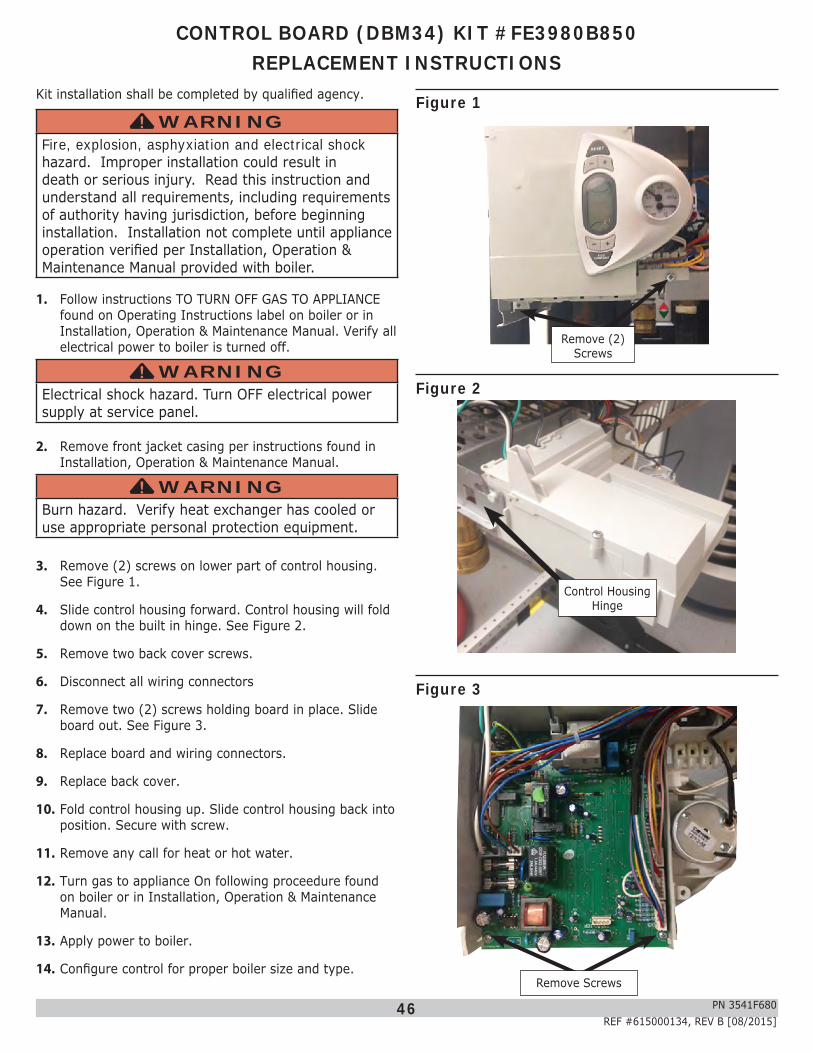
3. Remove (2) screws on lower part of control housing. See Figure 1.
4. Slide control housing forward. Control housing will fold down on the built in hinge. See Figure 2.
5. Remove two back cover screws.
6. Disconnect all wiring connectors
7. Remove two (2) screws holding board in place. Slide board out. See Figure 3.
8. Replace board and wiring connectors.
9. Replace back cover.
10. Fold control housing up. Slide control housing back into position. Secure with screw.
11. Remove any call for heat or hot water.
12. Turn gas to appliance On following proceedure found on boiler or in Installation, Operation & Maintenance Manual.
13. Apply power to boiler.
14. Configure control for proper boiler size and type.
CONTROL BOARD (DBM34) KIT #FE3980B850REPLACEMENT INSTRUCTIONS
Figure 1
Figure 2
Figure 3
Control Housing Hinge
Remove Screws
PN 3541F680REF #615000134, REV B [08/2015]
Remove (2) Screws
47
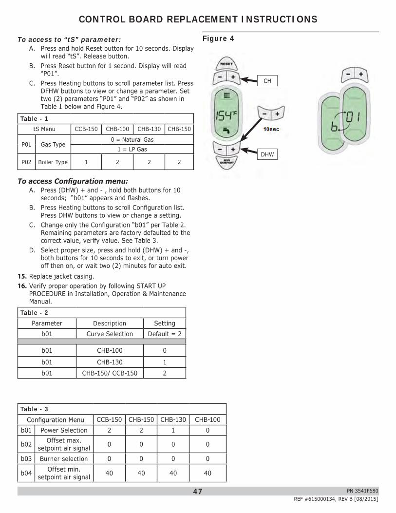
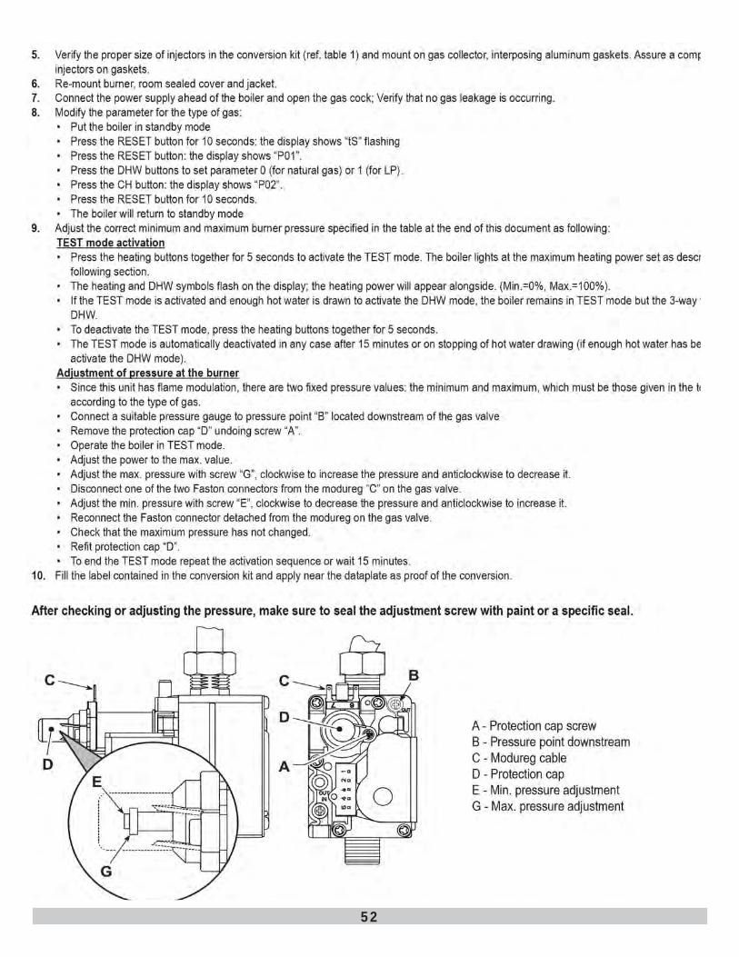
To access to “tS” parameter:A. Press and hold Reset button for 10 seconds. Display
will read “tS”. Release button.B. Press Reset button for 1 second. Display will read
“P01”.C. Press Heating buttons to scroll parameter list. Press
DFHW buttons to view or change a parameter. Set two (2) parameters “P01” and “P02” as shown in Table 1 below and Figure 4.
Table - 1tS Menu CCB-150 CHB-100 CHB-130 CHB-150
P01 Gas Type0 = Natural Gas
1 = LP Gas
P02 Boiler Type 1 2 2 2
To access Configuration menu:A. Press (DHW) + and - , hold both buttons for 10
seconds; “b01” appears and flashes.B. Press Heating buttons to scroll Configuration list.
Press DHW buttons to view or change a setting.C. Change only the Configuration “b01” per Table 2.
Remaining parameters are factory defaulted to the correct value, verify value. See Table 3.
D. Select proper size, press and hold (DHW) + and -, both buttons for 10 seconds to exit, or turn power off then on, or wait two (2) minutes for auto exit.
15. Replace jacket casing.16. Verify proper operation by following START UP
PROCEDURE in Installation, Operation & Maintenance Manual.
Table - 2Parameter Description Setting
b01 Curve Selection Default = 2
b01 CHB-100 0
b01 CHB-130 1b01 CHB-150/ CCB-150 2
CONTROL BOARD REPLACEMENT INSTRUCTIONS
Table - 3Configuration Menu CCB-150 CHB-150 CHB-130 CHB-100
b01 Power Selection 2 2 1 0
b02 Offset max. setpoint air signal 0 0 0 0
b03 Burner selection 0 0 0 0
b04 Offset min. setpoint air signal 40 40 40 40
Figure 4
CH
DHW
PN 3541F680REF #615000134, REV B [08/2015]
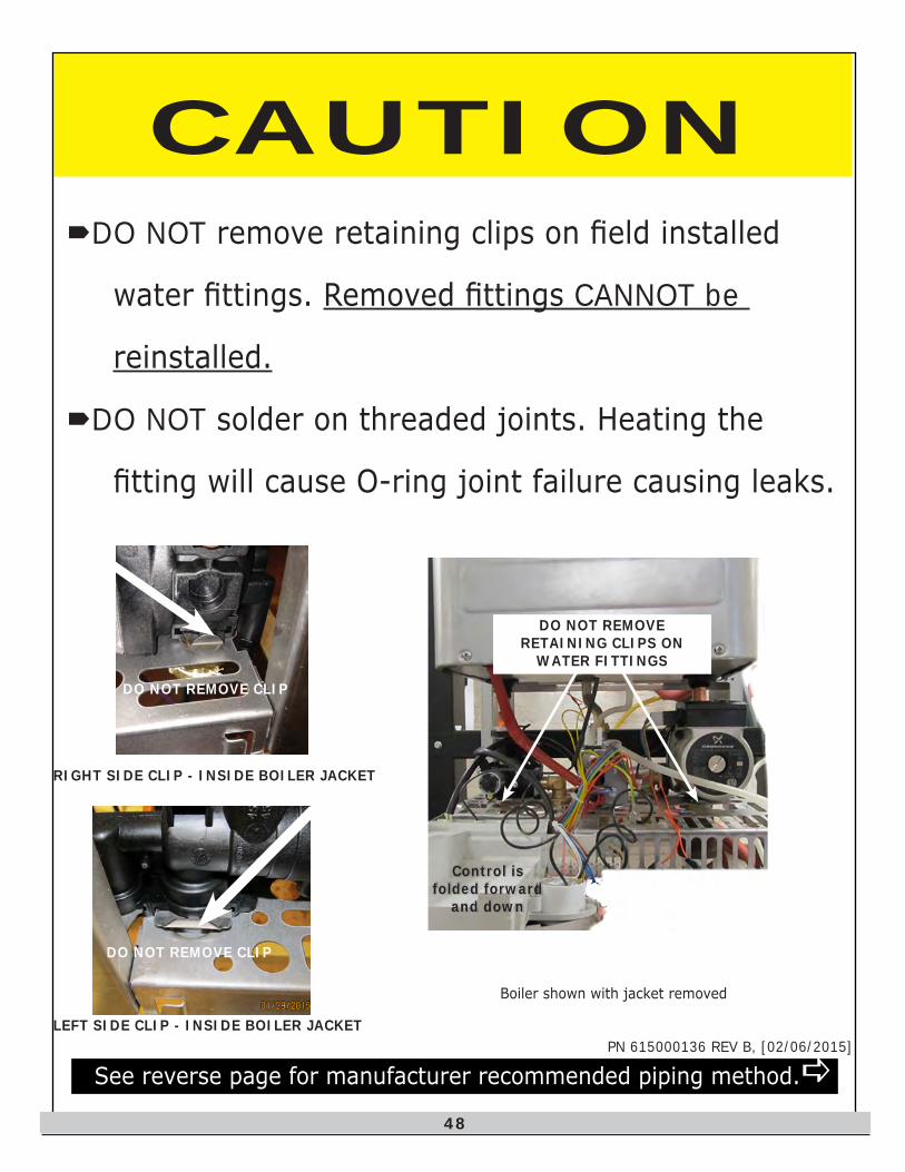
CAUTIONDO NOT remove retaining clips on field installed
water fittings. Removed fittings CANNOT be
reinstalled.
DO NOT solder on threaded joints. Heating the
fitting will cause O-ring joint failure causing leaks.
Boiler shown with jacket removed
Control is folded forward
and down
RIGHT SIDE CLIP - INSIDE BOILER JACKET
LEFT SIDE CLIP - INSIDE BOILER JACKET
DO NOT REMOVE CLIP
DO NOT REMOVE CLIP
See reverse page for manufacturer recommended piping method.
DO NOT REMOVE RETAINING CLIPS ON
WATER FITTINGS
PN 615000136 REV B, [02/06/2015]
48
PN 615000136 REV B, [02/06/2015]
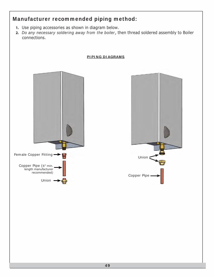
Manufacturer recommended piping method:1. Use piping accessories as shown in diagram below.2. Do any necessary soldering away from the boiler, then thread soldered assembly to Boiler
connections.
Female Copper Fitting
Copper Pipe (6” min. length manufacturer
recommended)
Union
PIPING DIAGRAMS
Copper Pipe
Union
49
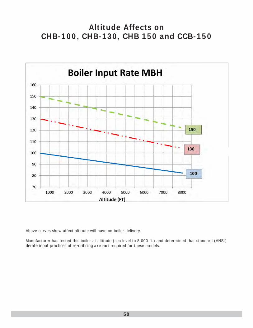
Altitude Affects on CHB-100, CHB-130, CHB 150 and CCB-150
Above curves show affect altitude will have on boiler delivery.
Manufacturer has tested this boiler at altitude (sea level to 8,000 ft.) and determined that standard (ANSI) derate input practices of re-orificing are not required for these models.
50

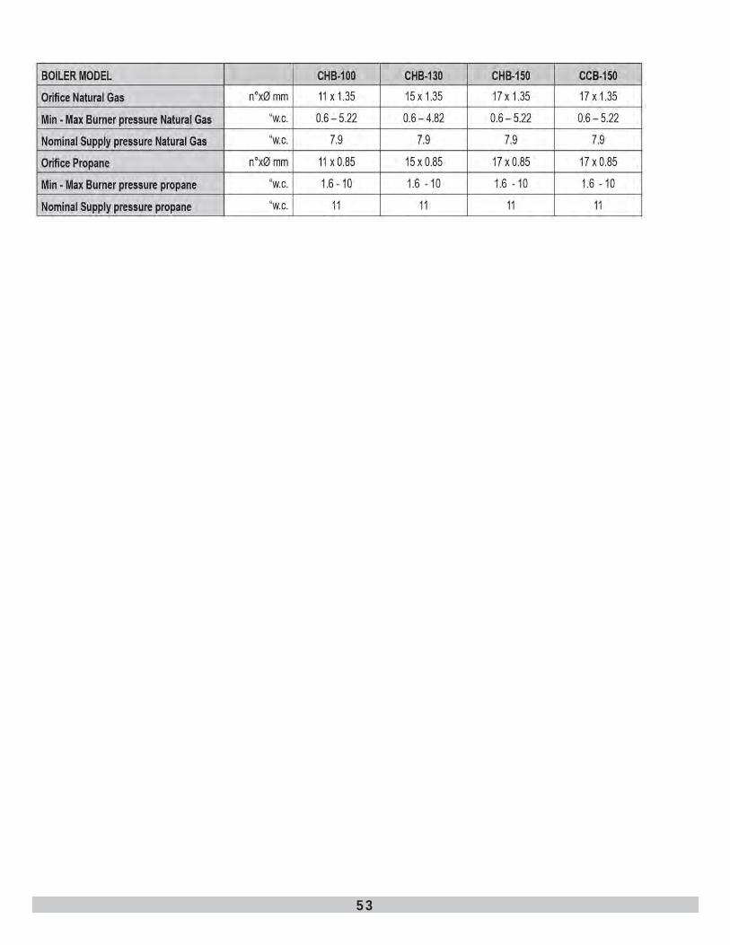
51
52
53

NOTES

NOTES

ECR International, Inc.2201 Dwyer Avenue
Utica . NY . 13501www.ecrinternational.com