wall fans with circular connection - taloon.com
TRANSCRIPT

www.ostberg.com
CV/KV, RSWall fans with circular connection
Fresh air from

W A L L F A N S . . . . . . . . . . . . . . . . . . . . . . .3
C V / K V 1 0 0 A / C . . . . . . . . . . . . . . . . . .4C V / K V 1 2 5 A / C . . . . . . . . . . . . . . . . . .4C V / K V 1 6 0 B / C . . . . . . . . . . . . . . . . . . .5C V / K V 2 0 0 A / B . . . . . . . . . . . . . . . . . .5C V / K V 2 5 0 A / C . . . . . . . . . . . . . . . . . .6C V / K V 3 1 5 B / C . . . . . . . . . . . . . . . . . . .6
A C C E S S O R I E S . . . . . . . . . . . 7
R S 8 0 A / C . . . . . . . . . . . . . . . . . . . . . . . .8R S 1 0 0 A / C . . . . . . . . . . . . . . . . . . . . . . .8R S 1 2 5 A / C . . . . . . . . . . . . . . . . . . . . . . .9R S 1 6 0 A / C . . . . . . . . . . . . . . . . . . . . . . .9
G E N E R A L F A N F A C T S . . . . . . .1 0 - 1 1
Contents
© AB C.A. Östberg, Avesta, Sweden, 2008. All rights reserved.No parts of this broschure may be reproduced or transmitted in any form or by any mean, without the written permission by AB C.A. Östberg.AB C.A. Östberg preserve the right to changes without further notice.

C V A N D K V
W A L L F A N S
The CV and KV
are identical ex-
cept for the mo-
unting plates; KV
has a square one,
while the CV has
a circular. This
combined with
ease of positio-
ning allows for a
wide variety of applications, inclu-
ding use in damp and humid envi-
ronments.
The wall fans are manufactured
from galvanised steel and are fitted
with external rotor type motors with
ball bearing and radial backward cur-
ved impeller blades.. The fan speed
can be controlled by voltage/fre-
quency variation.
There are 6 sizes of CV and KV
with 12 different capacities.
R S , E X T E R N A L W A L L
M O U N T E D F A N
The RS are a range of
exhaust fans designed for
mounting on an external
wall. All fans are fitted
with an external rotor
motor with in-built
motor protection.
The fans have backward curved
impeller blades for high performance
and the fan speed can be controlled
by voltage/frequency variation. The
casings are manufactured from pain-
ted galvanised steel for high durabili-
ty.
RS is available in 4 sizes and 8
different capacities.
3
Wall fans from Östberg

P R E S S U R E / F L O W
4
C V / K V 1 0 0 A / CC V / K V 1 2 5 A / CWall fan with backward curved impeller
T E C H N I C A L D A T A
S O U N D D A T AI N P U T / F L O W
C V / K V 1 0 0 A / C
CV/KV 100 A, 40 l/s 125 Pa LpA LwA tot dB (A) 63 125 250 500 1K 2K 4K 8K
Environment 36 43 35 21 33 35 39 37 37 31
Inlet 66 45 56 64 60 58 52 45 38
CV/KV 100 C, 60 l/s 170 Pa LpA LwA tot dB (A) 63 125 250 500 1K 2K 4K 8K
Environment 42 49 34 23 40 40 44 42 44 38
Inlet 70 50 61 66 65 65 59 52 46
D I M E N S I O N S (mm)
A C C E S S O R I E S
Safety grille, thermostat, louvre & back draught shutter,
transformer controllers
General fan facts, page 10-11.
CV/KV 100 A 100 C
Voltage, V/Hz 230/50 230/50
Current, A 0,18 0,27
Input, W 41 62
Speed, rpm 1730 2530
Weight, kg 2,5 2,5
Wiring diagram 4040002 4040001
Capacitor, μF 3 2
Insulation class, motor F F
Motor protection IP 44 IP 44
P R E S S U R E / F L O W T E C H N I C A L D A T A
S O U N D D A T AI N P U T / F L O W
C V / K V 1 2 5 A / C
CV/KV 125 A, 40 l/s 130 Pa LpA LwA tot dB (A) 63 125 250 500 1K 2K 4K 8K
Environment 36 43 35 20 35 34 38 38 36 30
Inlet 67 44 51 66 60 56 52 47 39
CV/KV 125 C, 80 l/s 145 Pa LpA LwA tot dB (A) 63 125 250 500 1K 2K 4K 8K
Environment 42 49 36 25 39 39 44 43 45 36
Inlet 70 49 55 64 67 64 60 55 48
D I M E N S I O N S (mm)
General fan facts, page 10-11.
CV/KV 125 A 125 C
Voltage, V/Hz 230/50 230/50
Current, A 0,18 0,27
Input, W 40 62
Speed, rpm 1640 2480
Weight, kg 2,5 2,5
Wiring diagram 4040002 4040001
Capacitor, μF 3 2
Insulation class, motor F F
Motor protection IP 44 IP 44
A C C E S S O R I E S
Safety grille, thermostat, louvre & back draught shutter,
transformer controllers
1 = Connected to duct at the induction side.2 = Not connected to duct.
1 = Connected to duct at the induction side.2 = Not connected to duct.
CV
KV
CV
KV

5
C V / K V 1 6 0 B / CC V / K V 2 0 0 A / B
Wall fan with backward curved impeller
P R E S S U R E / F L O W T E C H N I C A L D A T A
S O U N D D A T AI N P U T / F L O W
C V / K V 1 6 0 B / C
CV/KV 160 B, 70 l/s 195 Pa LpA LwA tot dB (A) 63 125 250 500 1K 2K 4K 8K
Environment 42 49 35 24 39 40 45 44 44 32
Inlet 69 48 54 64 65 63 58 53 48
CV/KV 160 C, 160 l/s 190 Pa LpA LwA tot dB (A) 63 125 250 500 1K 2K 4K 8K
Environment 49 56 35 34 42 49 54 47 48 35
Inlet 73 52 60 64 68 69 64 64 54
D I M E N S I O N S (mm)
General fan facts, page 10-11.
CV/KV 160 B 160 C
Voltage, V/Hz 230/50 230/50
Current, A 0,27 0,44
Input, W 62 105
Speed, rpm 2540 2480
Weight, kg 2,8 4,0
Wiring diagram 4040001 4040001
Capacitor, μF 2 3
Insulation class, motor F F
Motor protection IP 44 IP 44
P R E S S U R E / F L O W T E C H N I C A L D A T A
S O U N D D A T AI N P U T / F L O W
C V / K V 2 0 0 A / B
CV/KV 200 A, 190 l/s 190 Pa LpA LwA tot dB (A) 63 125 250 500 1K 2K 4K 8K
Environment 47 54 34 31 42 46 50 47 48 34
Inlet 72 52 60 64 67 66 64 65 55
CV/KV 200 B, 160 l/s 300 Pa LpA LwA tot dB (A) 63 125 250 500 1K 2K 4K 8K
Environment 48 55 35 30 40 48 52 48 49 41
Inlet 73 52 62 66 67 66 65 64 58
D I M E N S I O N S (mm)
General fan facts, page10-11.
CV/KV 200 A 200 B
Voltage, V/Hz 230/50 230/50
Current, A 0,51 0,69
Input, W 115 158
Speed, rpm 2580 2500
Weight, kg 4,1 4,8
Wiring diagram 4040001 4040001
Capacitor, μF 4 4
Insulation class, motor F F
Motor protection IP 44 IP 44
A C C E S S O R I E S
Safety grille, thermostat, louvre & back draught shutter,
transformer controllers
A C C E S S O R I E S
Safety grille, thermostat, louvre & back draught shutter,
transformer controllers
1 = Connected to duct at the induction side.2 = Not connected to duct.
1 = Connected to duct at the induction side.2 = Not connected to duct.
CV
KV
CV
KV

P R E S S U R E / F L O W
C V / K V 2 5 0 A / CC V / K V 3 1 5 B / CWall fan with backward curved impeller
T E C H N I C A L D A T A
S O U N D D A T AI N P U T / F L O W
C V / K V 2 5 0 A / C
CV/KV 250 A, 135 l/s 250 Pa LpA LwA tot dB (A) 63 125 250 500 1K 2K 4K 8K
Environment 47 54 26 30 34 47 52 47 44 38
Inlet 74 51 60 67 67 69 68 64 55
CV/KV 250 C, 160 l/s 320 Pa LpA LwA tot dB (A) 63 125 250 500 1K 2K 4K 8K
Environment 49 56 26 38 40 50 53 49 46 40
Inlet 74 52 59 66 67 69 69 66 60
D I M E N S I O N S (mm)
General fan facts, page 10-11.
CV/KV 250 A 250 C
Voltage, V/Hz 230/50 230/50
Current, A 0,53 0,84
Input, W 120 192
Speed, rpm 2580 2420
Weight, kg 4,1 4,9
Wiring diagram 4040001 4040001
Capacitor, μF 4 5
Insulation class, motor F F
Motor protection IP 44 IP 44
P R E S S U R E / F L O W T E C H N I C A L D A T A
S O U N D D A T AI N P U T / F L O W
C V / K V 3 1 5 B / C
D I M E N S I O N S (mm)
General fan facts, page 10-11.
CV/KV 315 B 315 C
Voltage, V/Hz 230/50 230/50
Current, A 0,84 1,19
Input, W 190 274
Speed, rpm 2465 2500
Weight, kg 5,5 6,0
Wiring diagram 4040001 4040001
Capacitor, μF 5 8
Insulation class, motor F F
Motor protection IP 44 IP 44
CV/KV 315 B, 220 l/s 300 Pa LpA LwA tot dB (A) 63 125 250 500 1K 2K 4K 8K
Environment 47 54 28 35 43 48 49 50 45 41
Inlet 74 54 56 61 65 65 70 67 65
CV/KV 315 C, 180 l/s 425 Pa LpA LwA tot dB (A) 63 125 250 500 1K 2K 4K 8K
Environment 50 57 30 35 44 51 51 53 50 43
Inlet 75 58 60 67 66 66 72 68 66
6
A C C E S S O R I E S
Safety grille, thermostat, louvre & back draught shutter,
transformer controllers
A C C E S S O R I E S
Safety grille, thermostat, louvre & back draught shutter,
transformer controllers
1 = Connected to duct at the induction side.2 = Not connected to duct.
1 = Connected to duct at the induction side.2 = Not connected to duct.
CV
KV
CV
KV

7
D U C T C L A M P, M K
The fan is connected to the duct
using duct clamp MK. The clamp is
made from pre-galvanized steel and
is rubber-lined to seal the connection
and absorb vibrations. Available in
sizes Ø 80-630 mm.
S A F E T Y G R I L L E , B S V
Made of pre-galvanised steel mesh
with angled lugs for fitting pipes.
Available in sizes Ø 80-800 mm.
B A C K D R A U G H T
S H U T T E R , R S K
For fitting in circular ducts. Made
from pre-galvanised steel with
spring-loaded vanes of aluminium.
Can be fitted in any position and is
available in the diameters Ø 100-630
mm.
L O U V R E S H U T T E R , V K
Self-closing louvre shutters with a
very low air flow resistance. Availab-
le in 14 sizes.
A C C E S S O R I E S
W A L L G R I D , Y G
Wall grid YG is manufactured from
die-cast aluminium with a 4 mm
thickness of material. The grid is
designed for outside use, and is equ-
ipped with a fine meshed net as stan-
dard. YG has circular fittings adap-
table for ventilation ducts. Available
in the diameters Ø 100-315 mm.
S I L E N C E R , L D C
Circular silencers in sizes of 100 mm
to 315 mm in diameter. Each size is
available in either a length of 600
mm or 900 mm. The silencer is com-
posed by a perforated duct, gables
and outer sheet, all of galvanized
steel. In between there are insulation
made of rock wool.
T H Y R I S T O R
C O N T R O L L E R , V R S
For manual variable speed control of
single-phase motors. Minimum speed
is adjusted by means of a screw under
the knob. The controller is certified
and approved as conforming to elect-
rical safety and interference regula-
tions on all markets. All single-phase
fans from Östberg can be regulated
with VRS controller.
T R A N S F O R M E R -
C O N T R O L L E R S
For high and low speed control of
single phase and 3-phase motors. The
controller is enclosed in a durable
PVC-housing.
V A R I A B L E S P E E D
C O N T R O L , E T F V
For single phase motors with 0-10 V
signal.
R E G U L A T O R , F R E 6
FRE 6 is intended to be used in ven-
tilation systems to regulate single
phase fans in five different regula-
tion programs, which are built in to
the regulator.

8
P R E S S U R E / F L O W
I N P U T / F L O W
R S 8 0 A / C
D I M E N S I O N S (mm)
R S 8 0 A / C R S 1 0 0 A / CExternal wall mounted fan with backward curved impeller
General fan facts, page 10-11.
T E C H N I C A L D A T A
RS 80 A C
Voltage, V/Hz 230/50 230/50
Current, A 0,20 0,32
Input, W 45 74
Speed, rpm 1850 2520
Weight, kg 3,4 3,4
Wiring diagram 4040002 4040001
Capacitor, μF 3 2
Insulation class, motor F F
Motor protection IP 44 IP 44
P R E S S U R E / F L O W
S O U N D D A T A
I N P U T / F L O W
R S 1 0 0 A / C
D I M E N S I O N S (mm)T E C H N I C A L D A T A
RS 100 A C
Voltage, V/Hz 230/50 230/50
Current, A 0,21 0,34
Input, W 48 76
Speed, rpm 1830 2490
Weight, kg 3,4 3,4
Wiring diagram 4040002 4040001
Capacitor, μF 3 2
Insulation class, motor F F
Motor protection IP 44 IP 44
S O U N D D A T A
RS 80 A, 30 l/s 125 Pa LpA LwA tot dB (A) 63 125 250 500 1K 2K 4K 8K
Environment 57 64 31 39 52 59 62 58 51 43
Inlet 66 57 58 60 61 59 55 50 42
RS 80 C, 35 l/s 195 Pa LpA LwA tot dB (A) 63 125 250 500 1K 2K 4K 8K
Environment 63 70 36 43 56 64 67 63 58 49
Inlet 72 61 63 66 67 66 61 56 50
General fan facts, page 10-11.
RS 100 A, 35 l/s 105 Pa LpA LwA tot dB (A) 63 125 250 500 1K 2K 4K 8K
Environment 56 63 30 37 49 56 61 56 50 41
Inlet 67 58 59 61 61 60 55 50 42
RS 100 C, 35 l/s 195 Pa LpA LwA tot dB (A) 63 125 250 500 1K 2K 4K 8K
Environment 62 69 35 43 54 63 67 62 57 48
Inlet 73 60 61 66 68 67 62 57 53
A C C E S S O R I E S
Transformer and variable speed controllers, regulators
A C C E S S O R I E S
Transformer and variable speed controllers, regulators

9
R S 1 2 5 A / C R S 1 6 0 A / C
External wall mounted fan with backward curved impeller
P R E S S U R E / F L O W
I N P U T / F L O W
R S 1 2 5 A / C
D I M E N S I O N S (mm)
General fan facts, page 10-11.
T E C H N I C A L D A T A
RS 125 A C
Voltage, V/Hz 230/50 230/50
Current, A 0,20 0,32
Input, W 45 73
Speed, rpm 1400 2460
Weight, kg 3.4 3.4
Wiring diagram 4040002 4040001
Capacitor, μF 3 2
Insulation class, motor F F
Motor protection IP 44 IP 44
P R E S S U R E / F L O W
S O U N D D A T A
I N P U T / F L O W
R S 1 6 0 A / C
D I M E N S I O N S (mm)T E C H N I C A L D A T A
RS 160 A C
Voltage, V/Hz 230/50 230/50
Current, A 0,29 0,46
Input, W 64 104
Speed, rpm 1200 2480
Weight, kg 5,0 5,0
Wiring diagram 4040002 4040001
Capacitor, μF 3 3
Insulation class, motor F F
Motor protection IP 44 IP 44
S O U N D D A T A
RS 125 A, 39 l/s 90 Pa LpA LwA tot dB (A) 63 125 250 500 1K 2K 4K 8K
Environment 55 62 41 40 50 56 58 55 44 35
Inlet 63 63 54 58 58 56 51 42 28
RS 125 C, 50 l/s 145 Pa
Environment 62 69 48 41 56 63 66 63 54 46
Inlet 70 55 59 63 65 63 59 51 40
General fan facts, page 10-11.
RS 160 A, 68 l/s 95 Pa LpA LwA tot dB (A) 63 125 250 500 1K 2K 4K 8K
Environment 51 58 48 38 49 53 52 50 40 32
Inlet 61 45 53 55 56 54 45 37 19
RS 160 C, 138 l/s 210 Pa
Environment 64 71 48 44 60 66 66 64 58 46
Inlet 73 520 60 66 70 68 59 55 41
A C C E S S O R I E S
Transformer and variable speed controllers, regulators
A C C E S S O R I E S
Transformer and variable speed controllers, regulators

D E S C R I P T I O N• The fan is used for transportation of “clean”
air, meaning not intended for fire-dangerous substances, explosives, grinding dust, soot,etc.
• The fan is equipped with an asynchronous external rotor induction motor with mainte-nance-free sealed ball-bearings.
• The capacitor has finite lifetime and should be exchanged after 45.000 hours of opera-tion (about 5 years) to secure maximum function. Defective capacitor can cause damage.
• To achieve maximum life time for installa-tions in damp or cold environments, the fan should be operating continuously.
• The fan can be installed outside or in other damp environments. Make sure that the fan-house is equipped with drainage.
• All fans are as standard, single phase 230V,50 Hz and 220V, 60 Hz. Other voltages/fre-quencies on request.
• The fan can be installed in any position.
I N S T A L L A T I O N• The fan must be installed according to the air
direction label on the fan.• The fan must be connected to duct or equip-
ped with a safety grille.• The fan should be installed in a safe way and
make sure that no foreign objects are left be-hind.
• The fan should be installed in a way that makes service and maintenance easy.
• The fan should be installed in a way that vibrations can not be transfused to duct or building. To provide this, use for example a duct clamp.
• To regulate the speed, a transformer, a triac or a frequency converter can be connected.
• A wiring diagram is applied on the inside of the junction box or separately enclosed.
• The fan must be installed and connected electrically in the correct way grounded.
• Electrical installations must be made by an authorized electrician.
• Electrical installations must be connected to a locally situated tension free switcher or by a lockable head switcher.
O P E R A T I O NWhen starting, make sure that:• the connecting voltage is in between +6% to
–10% of the rated voltage.• no noise appears when starting the fan.
H O W T O H A N D L E• The fan must be transported in its packing
until installation. This prevents transport damages, scratches and the fan from getting dirty.
M A I N T E N A N C E• Before service, maintenance or repair begins,
the fan must be tension free and the impeller must have stopped.
• The fan must be cleaned when needed, at least once per year to maintain the capacity and to avoid unbalance which may cause unnecessary damages on the bearings.
• The fan bearings are maintenance-free and should be renewed only when necessary.
• When cleaning the fan, high-pressure clea-ning or strong dissolvent must not be used.
• Cleaning should be done without dislodging or damaging the impeller.
• Make sure that there is no noise from the fan.
F A U LT D E T E C T I O N1. Make sure that there is tension to the fan.2. Cut the tension and verify that the impeller
is not blocked.3. Check the thermo-contact/motor protector.
If it is disconnected the cause of overheatingmust be taken care of, not to be repeated. To restore the manual thermo-protector the tension will be cut for a couple of minutes.Larger motors than 1,6 A may have manual resetting on the motor. If it has automaticthermo-protector the resetting will be done automatically when the motor is cold.
4. Make sure that the capacitor is connected,(single phase only) according to the wiring diagram.
5. If the fan still does not work, the first thing to do is to renew the capacitor.
6. If nothing of this works, contact your fan supplier.
7. If the fan is returned to the supplier, it must be cleaned, the motor cable undamaged and a detailed nonconformity report enclosed.
W A R R A N T YThe warranty is only valid under condition thatthe fan is used according to this “Directions foruse”.
10
1~ 1~
Wiring diagrams4 0 4 0 0 0 1 Single phase
Key to model types
G E N E R A L F A N F A C T S
4 0 4 0 0 0 2Single phase
K V 1 2 5 A/C
Wall fan
Connecting dimension
CapacityK=SquareC=Circular
11
G E N E R A L F A N F A C T S
In pressure/flow diagrams or in the table oftechnical data there are facts about highest tem-perature of transported air.
All motors have insulation class F whichmeans that the thermal contact disconnects thepower when the winding temperature is maxi-
mum 155°C. At this winding temperature thelife time of the ball bearings is not optimal. Thisis why the ambient temperature is shown at alower winding temperature so the life time ofball bearings becomes optimal.
The winding temperature variates in the dia-grams and depending on differences in power/current consumption. The temperatures in ourdiagrams are given at the highest winding tem-perature.
Temperature of transported air
Sound data explanationS O U N D D A T A I N T H I SB R O C H U R E I S B A S E D O N F O L -L O W I N G D E F I N I T I O N S :The points for which the sound data is present-ed are along the system line defined by thepressure and flow stated in the sound data tablefor each fan. There are three types of sound inthese tables; inlet- and outlet sound are mea-sured in duct, while the surrounding sound ismeasured outside the fan and duct system. Forall these types of sound, the sound power levelsare presented in octave bands. For the sur-rounding sound, also the sound pressure levelhas been calculated.
T H E S O U N D P O W E R L E V E LThe sound power level, Lw(A) is used to calcu-late the sound from the whole ventilation sys-tem. This system can be a composition of gril-les, dampers and diffusers for example.
The sound power level is a measured valueaccording to standards, and it does not tell howthe sound appears as the sound power is inde-pendent of the characteristics of the placementof the fan. In order to resemble the human ear,the A-filter is used indicated with Lw(A) mea-sured in dB(A).
T H E S O U N D P R E S S U R E L E V E LThe sound pressure level, Lp or Lp(A), tellshow the human ear registrates the sound. It isdependent on the sound power level, distancefrom the source, restrictions of the propagationand the accoustic characteristics of the room.
The sound pressure level is presented for aroom with an equivalent absorption area of20 m2 at a distance of 3 m, where the sound isemitted in a semi spherical propagation.
The sound pressure level can be calculated as:
Lp=Lw + 10Log (Q/4πr2 + 4/A)
where A is the room’s equivalent absorption area and Q is the propagation type:Q=1 is spherical propagationQ=2 is semi spherical propagationQ=4 is quarter spherical propagation.
Thus, for the above specified properties of theplacement of the fan, the difference betweensound pressure and sound power is:
Lp-Lw=10log(2/4π32+4/20)=~-7dB,
which is the difference that can be seen in the tables of sound data for each fan. For the freefield case, i.e. from a roof fan, the sound pres-sure level is calculated as:Lp=Lw+10log(2/4πr2).
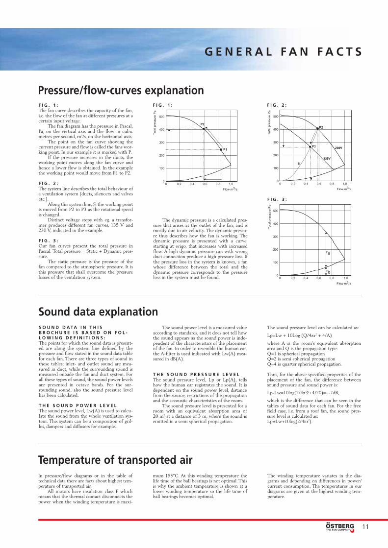
F I G . 1 : The fan curve describes the capacity of the fan,i.e. the flow of the fan at different pressures at acertain input voltage.
The fan diagram has the pressure in Pascal,Pa, on the vertical axis and the flow in cubicmetres per second, m3/s, on the horizontal axis.
The point on the fan curve showing thecurrent pressure and flow is called the fans wor-king point. In our example it is marked with P.
If the pressure increases in the ducts, theworking point moves along the fan curve andhence a lower flow is obtained. In the examplethe working point would move from P1 to P2.
F I G . 2 :The system line describes the total behaviour ofa ventilation system (ducts, silencers and valvesetc.).
Along this system line, S, the working pointis moved from P2 to P3 as the rotational speedis changed.
Distinct voltage steps with eg. a transfor-mer produces different fan curves, 135 V and230 V, indicated in the example.
F I G . 3 :Our fan curves present the total pressure inPascal. Total pressure = Static + Dynamic pres-sure.
The static pressure is the pressure of thefan compared to the atmospheric pressure. It is this pressure that shall overcome the pressurelosses of the ventilation system.
The dynamic pressure is a calculated pres-sure that arises at the outlet of the fan, and ismostly due to air velocity. The dynamic pressu-re thus describes how the fan is working. Thedynamic pressure is presented with a curve,starting at origo, that increases with increasedflow. A high dynamic pressure can with wrongduct connection produce a high pressure loss. Ifthe pressure loss in the system is known, a fanwhose difference between the total and thedynamic pressure corresponds to the pressureloss in the system must be found.
Pressure/flow-curves explanationF I G . 1 : F I G . 2 :
F I G . 3 :

ÖSTBERG - THE FAN COMPANY
AB C.A.ÖstbergBox 54, SE-774 22 Avesta, Sweden
Tel: +46 226 860 00Fax: +46 226 860 05
E-mail: [email protected]
Fresh air from
AB
C.A
. Ö
stbe
rg/P
rinfo
Ave
sta
Off
set
08.
05
1.00
0 ex
.
Östberg – The Fan Company is one ofleading producers of centrifugal in-lineduct fans in the world.
30 years ago the founder and ownerwas one of the inventers of the first cen-trifugal in-line duct fan in the history.
We have continued to develope newproducts and today we offer a wide rangeof centrifugal in-line duct fans.
Our goal has always been to offerquality products at competitive prices.