w26 instruction manual
TRANSCRIPT
8/9/2019 W26 Instruction Manual
http://slidepdf.com/reader/full/w26-instruction-manual 1/304
P_0000045
0.0.1.Introduction
The purpose of this manual is to give the user a guide for operation and maintenance of the engine. This manual has
been prepared using the manufacturer's best knowledge and experience. The manual is part of the documentation
supplied with the engine.
It is imaginable that, before starting or during performing particular jobs, you have questions to which the manual
gives no answer. In this case do not take any unnecessary risks and contact the Service department of Wärtsilä
Corporation or your local Wärtsilä Service Office.
Wärtsilä Corporation reserves the right to minor alterations and improvements due to engine development without the
obligation to enter the corresponding changes in this manual.
The operation and/or maintenance work described in this manual must only be carried out by trained technicians
specialised in diesel engines.
Make sure, everyone who works with the engine has this manual available and understands the contents.
Ensure, all equipment and tools for maintenance are in good order.
Use only genuine parts to ensure the best efficiency, reliability and life time of the engine and its components.
Modifications as to the settings may only be made after written approval from Wärtsilä Corporation. Altering settings
may effect the warranty.
During the warranty period of the engine the owner is obliged to follow strictly the instructions for operation and
maintenance outlined in this manual.
The customer will be solely responsible in the following cases, among other things:
For failure caused by neglecting to consult the engine documentation, resulting in malfunction of the engine, shortlife time of components, personal injury or damage to property or environment.
For wrong treatment or mal operation, also when the circumstances are not described in the engine documentation.
For any consequence resulting from incorrect translation or interpretation of the original engine documentationsupplied with the engine.
0.0.2.Terminology
The following definitions are used in the engine documentation:
Operating side
Longitudinal side of the engine where the operating controls are located.
Non-operating side
Longitudinal side opposite of the operating side.
Driving end
End of the engine where the flywheel is located.
Free end
The end opposite the driving end.
Designation of cylinders
Designation of cylinders begins at the driving end.
Clockwise rotating
The rotation as viewed from the position of the observer.
0.0.General 0.0-PAAE062665-00
Printed by DSME 의장설계2팀 송승화 2009-06-02 17:28

8/9/2019 W26 Instruction Manual
http://slidepdf.com/reader/full/w26-instruction-manual 2/304
P_0000045
Counter-clockwise rotating
The rotation as viewed from the position of the observer.
A-bank and B-bank
See figure in relation to observer.
Inlet and exhaust valves
See figure in relation to observer.
Figure 0.0-1: Engine definitions
Top dead centre (TDC)
The top turning point of the piston in the cylinder. TDC for every cylinder is marked on the gradation of the flywheel.
In a complete diesel process on a four cycle engine the piston reaches TDC twice:
TDC at scavenging
The first time when the exhaust stroke of the previous working cycle ends and the suction stroke of the following one
begins. Exhaust valves as well as inlet valves are then partly open and scavenging takes place. If the crankshaft isturned back and forth in this TDC area, both exhaust and inlet valves tend to open, a fact that indicates the piston is
near top position which is called TDC at scavenging.
TDC at firing
The second time is at the end of the compression stroke and before the working stroke starts. Slightly before this TDC
the fuel injection takes place and this TDC can therefore be defined as TDC at firing. In this case, all valves are closed
and do not move if the crankshaft is turned. The roller of the fuel pump tappet is on the lifting side of the fuel cam.
Bottom dead centre (BDC)
The bottom turning point of the piston in the cylinder.
Marks on the flywheel
The circumference of the flywheel is divided into sections of 5°, starting at TDC of cylinder 1. TDC for every following
cylinder is individually indicated. Where two TDC's are indicated at the same mark, one cylinder is in TDC at firing and
the other in TDC at scavenging. See also the firing order in chapter [1.0.]
Printed by DSME 의장설계2팀 송승화 2009-06-02 17:28

8/9/2019 W26 Instruction Manual
http://slidepdf.com/reader/full/w26-instruction-manual 3/304
P_0000045
The indicator (1) is provided with a scale per degree, starting at 5° before TDC till 5° after TDC.
Figure 0.0-2: Example of reading the flywheel
Designation of bearings
Main bearings
The crankshaft locating bearing is No. 0, the first standard main bearing is No. 1, the second No. 2 etc. The crankshaft
locating bearing outer ring close to the flywheel is marked with 00 and the inner ring with 0.
Camshaft bearing
Camshaft bearings are designated in the same sequence as the main bearings.
Intermediate gear wheel bearings
Bearings located at flywheel side are designated 00 and the inner bearings 0.
Printed by DSME 의장설계2팀 송승화 2009-06-02 17:28

8/9/2019 W26 Instruction Manual
http://slidepdf.com/reader/full/w26-instruction-manual 4/304
P_0000045
Figure 0.0-3: Designation of main bearings / camshaft bearings
Printed by DSME 의장설계2팀 송승화 2009-06-02 17:28

8/9/2019 W26 Instruction Manual
http://slidepdf.com/reader/full/w26-instruction-manual 5/304

8/9/2019 W26 Instruction Manual
http://slidepdf.com/reader/full/w26-instruction-manual 6/304

8/9/2019 W26 Instruction Manual
http://slidepdf.com/reader/full/w26-instruction-manual 7/304
P_0000045
0.1.2.1.Hazards that may be due to moving parts
Running engine without covers, coming in contact with moving parts
Touching pump parts during unintentional start of el. driven pump motor
Charger starts to rotate due to draft if not locked during maintenance
Somebody sticks his hand into the compressor housing when the silencer is removed and engine running
Unexpected movement of valve or fuel rack(s) due to broken wire or soft / hardware failure in the control system
Unexpected movement of components
Turning device engaged during maintenance work, Turning device not engaged e.g. Turning device removed for overhaul, during maintenance work could cause
rotating crankshaft
Mechanical breakage (of e.g. speed sensor) due to erratic actuator assembly to engine or electrical connections.
0.1.2.2.Hazards that may be due to incorrect operating conditions
Overspeed or explosion due to air-gas mixture in the charge air
Overspeeding due to air-oil mist mixture in the charge air
Malfunction of crankcase ventilation
Oil mist detector will trip if water is present in lubricating oil
Crankcase explosion if oil mist is mixed with "fresh" air during inspection after an oil mist shut down
Crankcase safety explosion valves will open if there is a crankcase explosion.
0.1.2.3.Hazards that may be due to incorrect operating conditions
Fuel or gas pipe will burst and spray fuel / gas
Leakage of:
- lube oil,- high pressure water on DWI engines,- HT water,- charge air,- exhaust gas,- pressurised air from air container, main manifold or pipes,- high pressure gas and sealing oil on GD engines,
Fire or explosion due to leakage on fuel line,
Fire due to oil or fuel / gas leakage,
Explosion or fire if flammable gas/vapour is leaking into the insulation box,
Inhalation of exhaust gases or fuel gases due to leakage,
Failure of pneumatic stop,
Ejected components due to- breakdown of hydraulic tool,- breakdown of hydraulic bolt- breakdown of turbocharger,- high firing pressures,- major failure,
Ejection of:- pressurised liquids and gases from the block and pipings,- high pressure fluid due to breakdown of hydraulic tool,- high firing pressures,- gas due to high firing pressures,- pressurised gases from high pressure gas system- high pressure fluid due to breakdown of HP sealing oil pipe,- high pressure air during maintenance of oil mist detector main air supply piping,- cooling water or fuel/lube oil if sensor is loosened while the circuit is pressurised,- springs during maintenance work,
Oil spray if running without covers,
Ejection of fuel injector if not fastened and- turning device engaged and turned,
- engine turning due to closed generator breaker/coupling.
0.1.2.4.Hazards that may be due to electricity or incorrect connections of electricity
Fire or sparks due to damage or short circuit in electrical equipment,
Contact with electricity during maintenance work if power not disconnected,
Electrical hazard if grounding of electrical equipment is incorrect,
Printed by DSME 의장설계2팀 송승화 2009-06-02 17:29

8/9/2019 W26 Instruction Manual
http://slidepdf.com/reader/full/w26-instruction-manual 8/304
P_0000045
Electrical shock if electrical equipment has a lead isolation break or connector damage or is dismantled with powerconnected,
Overheating of control system component due to erratic electrical connections,
Incorrectly wired or disconnected emergency stop switch,
Overload of control system components due to damaged control circuitry or incorrect voltage,
Engine not controllable if failure in the shutdown circuitry,
Unexpected start up or overrun,
Crankcase explosion if:- engine not safeguarded at high oil mist levels, due to energy supply failure,
- engine not (fully) safeguarded at high oil mist levels, due to failure in oil mist detector circuitry,- engine not (fully) safeguarded at high oil mist levels, due to erratic electrical connector or leakage in pipeconnection.
0.1.2.5.Other hazards and hazardous situations where it's especially important to use personal safetyequipment
Slip, trip and fall,
Water additives and treatment products (see appendix 02A, section [02A.4]),
Touching the insulation box, turbo-charger, pipes exhaust manifold or (other) unprotected parts without protectionduring engine operation,
Dropping parts during maintenance work,
Starting maintenance work too early i.e. causing risk when handling hot components,
Neglecting use of cranes and/or lifting tools,
Not using proper tools during e.g. maintenance work,
Contact with fuel oil or oily parts during maintenance work (see appendix [02A]),
Noise level,
Touching or removing Turbocharger insulation,
Preloaded fixation springs during check / replacement of sensor.
0.1.3.Electro Static Discharge (ESD)
Note!
ESD, the invisible threat!
The components of modern printed circuit boards are sensitive to electrostatic discharge (ESD). Damages due to
electrostatic discharge can cause immediate failures of a printed circuit board, or can cause a problem since the
components start deteriorating. Pay always attention to ESD protection, just because the ESD damage is usually
invisible. Handle printed circuit boards, EPROMs and SRAM always carefully.
The static electricity is generally created when two materials are rubbed against each other. This causes unbalanced
electricity in the objects (or persons) and they become charged with a static electricity. On the other hand, conducting
materials in the environment usually have a balanced electrical situation. A discharge current is created when a
charged person touches a conducting object. Even when you move around you are continuously charged and
discharged, but normally that causes no damage. Those discharge currents, however, easily damage the thin layers in
integrated circuits.
The following precautions can widely reduce the risk of failures and malfunctions due to ESD:
Always keep the board in its protection bag/box during transportation and storage. Remove it from the bag justshortly before the installation.
Make sure your body always has the same potential as the table frame, the board, the rail, or the junction boxwhere you are going to install the printed circuit board. This can be done with the help of a special ground-terminalwith wristband, but also by simply touching the object with one hand and inserting the printed circuit board with theother hand.
Avoid touching the connector pins!
Use the protective bag under and between the boards while placing them on a table. Do not pass the board straight into the hands of another person except if is in a protective bag. It is also possible to
place the board on a non-conducting table and let the other person pick it up from there.
Clear the installation site from all the construction or the package material before the installation. Keep theenvironment tidy.
Before inserting the board into its frame or enclosure, check the frame or the enclosure is clean. Check theconnector pins are clean and straight so that the board can be easily inserted into its frame.
Printed by DSME 의장설계2팀 송승화 2009-06-02 17:29

8/9/2019 W26 Instruction Manual
http://slidepdf.com/reader/full/w26-instruction-manual 9/304
P_0000045
Do not place the board on a conducting surface such as a metallic table. If the board has been placed on aconducting table, place one hand on the table and lift the board with the other one.
Handle damaged boards as functional ones, because the damage grade is usually unknown.
0.1.4.Welding precautions
Introduction
This is an instruction concerning the treatment and the protection of the engine mounted electrical equipment when an
arc welding is performed in the vicinity.
Main principles:
Prevent uncontrolled current loops while welding.The welding current path must always be checked, there should be a straight route from the welding point back tothe return connection of the welding apparatus. The highest current is always going where it meets the lowestresistance, in certain cases the return current can therefore go via grounding wires and electronics in the controlsystem. To avoid this, the distance between the welding point and the return connection clamp of the weldingapparatus must always be as short as possible and without any electronic component in the return loop path. Payattention to the connectivity of the return connection clamp, a bad contact might also cause sparkles and radiations.
Radiations prevention.The welding current and the arc are emitting a wide spectrum of electromagnetic radiations. Those might causedamages on sensitive electronic equipment; in order to avoid those damages all cabinets and terminal boxes must
be kept closed while welding. Sensitive equipment can also be protected by means of shieldings with conductivemetal plates, avoid also the welding apparatus cables go in parallel with wires and cables of the control systemsince the high welding currents are going to easily induce secondary currents in conductive materials.
Damages prevention due to sparkles.Sparkles are commonly flying around from the welding arc. Few materials withstand the heat from these sparkles,therefore all cabinets and terminal boxes should be kept closed during the welding. Sensors, actuators, cables andadditional equipments on the engine must be properly protected. Sparkles can also be a problem after they havecooled down, i.e. while causing short circuits, sealing problems etc.
If it is convenient, disconnect all global signals like power supply, data communication etc.
Printed by DSME 의장설계2팀 송승화 2009-06-02 17:29

8/9/2019 W26 Instruction Manual
http://slidepdf.com/reader/full/w26-instruction-manual 10/304
P_0000045
1.0.1.Basic information
Project name Daewoo 3024
Engine designation number:
PAAE062665,
PAAE062666,
PAAE062667,
PAAE062668,
PAAE062669,
PAAE062670,
PAAE062671,
PAAE062672,
Engine type 16V26
Cylinder bore 260 mm
Stroke 320 mm
Number of cylinders 16
Direction of rotation Clockwise
Firing order A1-B1-A3-B3-A2-B2-A5-5B-
A8-B8-A6-B6-A7-B7-A4-B4
The Wärtsilä 26 diesel engine is a 4-stroke, medium speed, turbocharged and intercooled engine with direct fuel
injection.
1.0.2.Output
1.0.Main Data 1.0-PAAE062665-00
Engine output according to engine rating plate
Output 100% kW 5200
Engine speed rpm 900
Suction air temperature °C 45
Charge air coolant temperature °C 38
Engine output according to ISO substitute reference conditions
Output 100% kW 5200
Engine speed rpm 900
ISO 3046-1:1995(E) Substitute reference conditions
Ambient air pressure mbar 1000
Site altitude above sea level m 0
Suction air temperature °C 45
Charge air coolant temperature °C 38
Printed by DSME 의장설계2팀 송승화 2009-06-02 17:30

8/9/2019 W26 Instruction Manual
http://slidepdf.com/reader/full/w26-instruction-manual 11/304
P_0000045
Note!
The full output of the engine is available at the ISO substitute reference conditions. No compensation (uprating) is
allowed for operating conditions better than the ISO substitute reference conditions. For derating data see section
[1.0.3.]
Note!
Fuel limiter is set at 110 % for governing purposes only.
1.0.3.Derating conditions
0.35% per °C that suction the air temperature is above the ISO substitute reference condition.
0.40% per °C that the suction air temperature is below 15 °C.
0.30% per °C that the charge air coolant temperature is above the ISO substitute reference condition.
1.33% per kPa (10 mbar) that the total exhaust gas back pressure is above the ISO substitute reference condition.
0.4% per %o relative pressure loss in the charge air cooler 1).
0.5% per 10% glycol unless the charge air coolant temperature is reduced by 1°C for every 10% glycol in the
cooling water.
Note!
Data mentioned in Operating Data (section [1.0.4.] ) must stay at the nominal values
High operating temperatures can be caused by:
contamination of coolers
reduction of charge air pressure by:- contamination of turbocharger compressor and/or turbine- contamination of air in take filter
- contamination of air side cooler.- too much wear of the turbine.
deviation of setting of (individual) high pressure fuel pumps
worn fuel injectors
worn high pressure fuel pumps
high fuel CCAI value (> 870)
high ambient temperature.
Note!
Never change fuel rack settings to equalize the exhaust gas
temperature.
Total exhaust gas back pressure mbar 30
1 Derating of the engine output:
For the ISO substitute reference conditions see section [1.0.2.]
Derating is according to ISO 3046-1:1995(E) applying: hm = 0.90
2 Reduce engine load if operating temperatures of lubricating oil or cooling water exceed the nominal values or
exhaust gas tend to exceed the maximum values, see section [1.0.4.]
Printed by DSME 의장설계2팀 송승화 2009-06-02 17:30

8/9/2019 W26 Instruction Manual
http://slidepdf.com/reader/full/w26-instruction-manual 12/304

8/9/2019 W26 Instruction Manual
http://slidepdf.com/reader/full/w26-instruction-manual 13/304

8/9/2019 W26 Instruction Manual
http://slidepdf.com/reader/full/w26-instruction-manual 14/304

8/9/2019 W26 Instruction Manual
http://slidepdf.com/reader/full/w26-instruction-manual 15/304
P_0000045
Figure 1.1-1: Viscosity conversion diagram
Conversion from various viscosity units to [mm /s] can be made in the diagram, [fig. 1.1-1] . The
diagram should be used only for conversion of viscosities at the same temperature. The same temperature
should then be used when entering the viscosity / temperature point into the diagram of [fig. 1.1-2] .
Fuel oil viscosity and temperature
Proper atomization of fuel in the combustion chamber of the engine requires for each fuel a specific viscosity.
Controlled heating to obtain the corresponding temperatures is required. These temperatures can be determined from
the diagram in [fig. 1.1-2] . The diagram shows:
The viscosity-temperature lines for a number of viscosity grades. For residual fuels (ISO RM..) the viscosity isspecified at 100°C .
For distillate fuels (ISO DM..) the viscosity is specified at 40°C .
The line for 35 mm² /s at 100°C fuel for instance is the one running through points H and E.
Lines for fuels with other viscosities run parallel.
Printed by DSME 의장설계2팀 송승화 2009-06-02 17:30

8/9/2019 W26 Instruction Manual
http://slidepdf.com/reader/full/w26-instruction-manual 16/304
P_0000045
Figure 1.1-2: Viscosity temperature diagram
The (horizontal) line at 1000 mm² /s above which pumping is difficult.
The line with sharp bends through point G, which shows the minimum storage temperature for all viscosity classes.For higher viscosity class fuels a higher storage viscosity is accepted to limit the heating demand.
The line with sharp bends through point F, shows the required centrifuging temperature. For viscosity classes higherthan 40 mm² /s at 50°C a higher centrifuging viscosity than 14 mm² /s is accepted to save heating power. Finally
the line turns vertical at 97°C because boiling of the sealing and operating water in the centrifuge must be avoided.
With further increase of viscosity the throughput through the centrifuge must be reduced for maintaining therequired degree of purification.
The maximum temperature before the HP fuel pumps is 50 °C for LFO and 130 °C for HFO.
Example:
RM35 a fuel with a viscosity of 35 mm² /s at 100°C (point B) or 380 mm² /s at 50°C (point A):
At 80°C (point C) the estimate viscosity is 77 mm² /s.
Is pumpable above 37°C (point H).
Minimum storage temperature is 41°C (point G). It is advised to keep the fuel about 10°C above this temperature.
Centrifuging temperature is 97°C (point F).
Heating temperature before entering the engine for proper atomisation with a viscosity between the 24 and 16mm² /s, is maximum 127°C and minimum 112°C (point D and E).
Purification
Heavy fuel (residuals, and mixtures of residuals, distillate and DMC) must be purified in an efficient working centrifuge
before entering the day tank. The fuel should be heated before centrifuging.
Recommended temperatures, depending on the fuel viscosity, are stated in the diagram, see [fig. 1.1-2] .
Printed by DSME 의장설계2팀 송승화 2009-06-02 17:30

8/9/2019 W26 Instruction Manual
http://slidepdf.com/reader/full/w26-instruction-manual 17/304
P_0000045
Sufficient heating capacity is needed to make centrifuging at recommended levels possible. The temperature must be
controlled on ±2°C before centrifuge when centrifuging high viscosity fuels with densities approaching or exceeding
0.991 g/ml at 15°C.
Be sure the correct gravity disc is used. Never exceed the flow rates recommended for the centrifuge for the grade of
fuel in use. The lower the flow rate the better the purification efficiency.
Sufficient separating capacity is required. The best and most disturbance-free results are obtained with purifier and
clarifier in series. Alternatively the main and stand-by separators may run in parallel, but this makes heavier demands
on correct gravity disc choice and constant flow and temperature control to achieve optimum results. Flow rate
through the centrifuges should not exceed the maximum fuel consumption of the engine by more than 10 %.
In case pure distillate fuel is used, centrifuging is still recommended as fuel may be contaminated during transport and
in storage tanks. The full rated capacity of the centrifuge may be used provided the viscosity is less than 12 mm² /s at
centrifuging temperature.
1.1.2.4.Comments on fuel characteristics
Note!
High density fuels with low viscosity may have low ignition quality.
Recommended centrifuge flow rate
Viscosity at 100°C mm² /s - 10 15 25 35 45 55
Viscosity at 50°C mm² /s 12 40 80 180 380 500 730
Centrifuge flow % of rated capacity 10060
40
30
25
20
15
1 Viscosity determines the complexity of the fuel heating and handling system, which should be considered
when estimating installation economy. The standard engine fuel system is designed for fuels up to the viscosity
class 55.
2 When the density exceeds 0.991 g/ml at 15°C water, and to some extent solid matter, can no longer be
removed with certainty by a centrifuge. Centrifuging systems claiming to clean fuel oils with densities up to
1.010 g/ml at 15°C are on the market. If such systems of the so called controlled discharge design are
installed, fuels with densities up to 1.010 g/ml at 15°C may be used.
3 Higher sulphur content increases the risk for corrosion and wear, particularly at low loads, and may
contribute to high-temperature deposit formation. The lubricating oil specification must be matched to such
qualities.
4 High ash content causes abrasive wear, and may cause high temperature corrosion and contributes to
formation of deposits. The most harmful ash constituents are the vanadium-sodium combinations.
5 High vanadium content causes high temperature corrosion on hot parts like exhaust valves, particularly in
combination with high sodium content. The corrosion accelerates with increased temperatures (increased engine
output).
6 Sodium (Na)contributes to hot corrosion on hot parts like exhaust valves in combination with high vanadium
(V) content. Sodium also contributes strongly to fouling of the turbine blading of the turbocharger at high
exhaust gas temperature. The permissable content of Na of the cleaned fuel should be below 30 ppm.
7 High "carbon residue" may cause deposit formation in combustion chamber and exhaust system, particularly
at low engine output.
8 High content of asphaltenes may contribute to deposit formation in the combustion chamber and exhaust
systems (at low loads). Asphaltenes may under certain circumstances precipitate from the fuel and will block
filters and/or cause deposits in the fuel system. Precipitating asphaltenes may also cause excessive centrifuge
sludge.
9 Heavy fuels may contain up to 1 % water at delivery. Water can originate from the installation bunker tanks.
Printed by DSME 의장설계2팀 송승화 2009-06-02 17:30

8/9/2019 W26 Instruction Manual
http://slidepdf.com/reader/full/w26-instruction-manual 18/304
P_0000045
Ignition quality is not defined nor limited in marine residual fuel standards. The same applies to ISO-F-DMC marine
distillate fuel. The ignition quality of these fuels cannot for a variety of reasons be determined by methods used for
pure distillates, i.e. Diesel Index, Cetane Index and Cetane Number.
Low ignition quality may cause trouble during starting and at low load operation, especially at too low charge air
temperature. This may result in long ignition delay and as a consequence, in high firing pressure rise ratio. The
combustion will be more noisy in this case, known as "Diesel knock", i.e. hard, high pitch combustion noise. Diesel
knock increases mechanical load on components surrounding the combustion space, increases thermal load, increases
lube oil consumption and increases lube oil contamination. Basically a low viscosity, in combination with a high
density, will result in a low ignition quality and is expressed in a CCAI value.
Figure 1.1-3: Nomogram for deriving CCAI
What do the CCAI values mean?
Straight run residues show CCAI values (Calculated Carbon Aromaticy Index) in the 770 to 840 range and are very
good igniters. Cracked residues delivered as bunkers may range from 840 to, in exceptional cases, above 900.
Normal diesel engines should accept CCAI values up to 850 with no difficulties. CCAI values between 850 and 870 may
cause difficulties under unfavourable conditions such as low charge air temperatures, insufficient preheating of the
engine at the start, malfunctioning of fuel injection system (in particular, badly maintained nozzles).
CCAI values above 870 are not advised.
Note!
Although low ignition quality produces long ignition delay, advancing the ignition timing makes things only worse; fuel
is injected at a lower compression temperature and this will produce even longer ignition delay.
To avoid difficulties in the engine fuel injection system water must be removed.
10 Reduced ignition and combustion quality can be caused by using HFO from modern refinery processes
compared with "traditional" heavy fuels. HFO from modern refinery processes may approach at least some of
the limits of fuel characteristics.
11 Aluminum + Silicon. Fuels may contain highly abrasive particles composed of aluminium and silicon oxides
known as "catalytic fines" from certain refining processes. If not removed by efficient fuel treatment, wear of
Printed by DSME 의장설계2팀 송승화 2009-06-02 17:30

8/9/2019 W26 Instruction Manual
http://slidepdf.com/reader/full/w26-instruction-manual 19/304
P_0000045
1.1.3.Internal fuel system
General
The fuel system on the engine consists of a Low Pressure and a High Pressure part. Both parts are basically situated
inside the Hot Box.
The Low Pressure part consists of a fuel circulating pump, fine filter, HP fuel pump brackets, supply and return lines,pressure control valve and leak-off lines.The HP fuel pump brackets are described in chapter [2.9.] , "Injection system".
The High Pressure part consists of the High Pressure (HP) fuel pumps, fuel injectors and High Pressure fuel lines.These components are described in chapter [2.9.] , "Injection system".
The "Internal Fuel System" diagram is provided in Annex A - Internal systems/Pipe arrangement , of this Instruction
Manual.
Note!
For maintenance background information , safety aspects, tools, intervals, tolerances, inspection, tightening torque
and procedures see chapter [2.4]
1.1.4.Filter
The engine mounted duplex filter contains in each compartment a disposable filter cartridge. The contamination level
of the filters is indicated by a pressure differential system.
Figure 1.1-4: Fuel filter
Checking pressure drop over filter
Note!
high pressure fuel pumps, nozzles and cylinder liners can be expected in a few hours.
1 Check pressure drop over fuel oil filters.
2 If pressure drop is too high renew filter cartridges.
Printed by DSME 의장설계2팀 송승화 2009-06-02 17:30

8/9/2019 W26 Instruction Manual
http://slidepdf.com/reader/full/w26-instruction-manual 20/304
P_0000045
Frequently changing of filter cartridges is in general the result of excessive dirt or water in the fuel oil.
Check if external system is working properly, e.g. filters and separators.
Fuel filter cartridge exchange (see [fig. 1.1-4] )
Figure 1.1-5: Fuel filter selector valve
1.1.5.Draining of fuel system
As the fuel quantity in the supply and discharge line is relatively large, it is preferred to purge the fuel lines into a
waste tank before commencing any maintenance to this system and components.
3 Loosen locking lever (4). If this lever jams, is it posible to change the position by lifting it against the spring
tension and by turning it. Switch the selector valve (3) half way to pressurise the stand-by filter and open the
vent plug (1) partly of the stand-by filter.
4 Close the vent plug if only fuel escapes.
5 Turn the selector valve (3) completely over to switch off the dirty filter section.
6 Open the vent plug (1) partly of the filter which is switched off and check if the filter compartment is
pressureless.
7 Open the drain plug (2) partly and drain the filter compartment.
8 After the filter compartment is empty remove the vent plug (1), take off the top cover and remove the filter
cartridge.
9 Check and wipe the open compartment internally clean.
10 Insert a new cartridge.
(For filter element life time see section [2.4.1.2.] )
11 Close the filter compartment and mount vent plug (1), turn on the drain plug (2) and leave vent plug (1)
partly open.
12 Turn the selector valve (3) partly backwards and fill the empty filter compartment. After a massive flow of
fuel escapes close the vent plug (1).
13 Select the filter compartment by turning the selector valve complete to one of the filter compartments. The
position is indicated by pointer (5). See [fig. 1.1-5] . Lock selector valve (3) with lever (4).
Printed by DSME 의장설계2팀 송승화 2009-06-02 17:30

8/9/2019 W26 Instruction Manual
http://slidepdf.com/reader/full/w26-instruction-manual 21/304
P_0000045
Figure 1.1-6: Draining the engine fuel system
Figure 1.1-7: Draining the engine fuel system
1 Close the supply to the engine fuel system.
2 Remove the plugs (2) of the filter housing see [fig. 1.1-4] .
3 Open vent plugs (1) see [fig. 1.1-4] .
4 Remove plug (7) from the return manifold see [fig. 1.1-6] .
5 Open vent plugs (6) see [fig. 1.1-6] .
6 Open, on the A - and B - bank, plugs (9) of the end covers (8) see [fig. 1.1-7] .
7 Open plug (10) of the end cover (11)..
Printed by DSME 의장설계2팀 송승화 2009-06-02 17:30
8/9/2019 W26 Instruction Manual
http://slidepdf.com/reader/full/w26-instruction-manual 22/304
P_0000045
1.2.1.Lubricants
Lubricating oil should feature a number of physical and chemical qualities required for reliable diesel engine operation.
Apart from lubricating bearings, cylinder liners, gears, valve mechanism etc., cooling is an important function. The
main engine lubricating oil must also be able to neutralize combustion products on engine parts and to keep these
products well dispersed.
Under normal operation the engine lubricating oil is exposed to high pressures and temperatures. The oil is often finely
divided as a spray or mist, intimately mixed with air and subjected to catalytic effects of various contaminators.
Contact with air results in oxidation and the production of gums, resins and acids.
Other major contaminators are products of combustion, such as soot, ash and (partially) unburnt fuel mixed with the
lubricating oil on the cylinder wall. High sulphur content of the fuel may also accelerate the rate of oil deterioration.
Some of the contaminators can be removed by purification or filtering. Other contaminators eventually will accumulate
to the point where the oil must be discarded. To determine the condition of the oil regular sampling and testing is
necessary. The samples should therefore be sent to a qualified laboratory for a detailed analysis regarding the oil
condition.
The oil manufacturer remains responsible for the quality of the oil under operating conditions. It is the responsibility of
the operator together with the advise of the oil supplier and no-go criteria given by Wärtsilä Corporation, to determine
whether or not the oil should be refreshed.
1.2.1.1.Requirements
1.2.1.1.1.Main lubricating oil
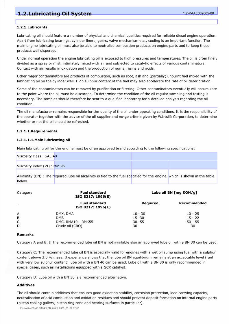
Main lubricating oil for the engine must be of an approved brand according to the following specifications:
Viscosity class : SAE 40
Viscosity index (VI) : Min.95
Alkalinity (BN) : The required lube oil alkalinity is tied to the fuel specified for the engine, which is shown in the table
below.
Remarks
Category A and B: If the recommended lube oil BN is not available also an approved lube oil with a BN 30 can be used.
Category C: The recommended lube oil BN is especially valid for engines with a wet oil sump using fuel with a sulphur
content above 2.0 % mass. If experience shows that the lube oil BN equilibrium remains at an acceptable level (fuel
with very low sulphur content) lube oil with a BN 40 can be used. Lube oil with a BN 30 is only recommended in
special cases, such as installations equipped with a SCR catalyst.
Category D: Lube oil with a BN 30 is a recommended alternative.
Additives
The oil should contain additives that ensures good oxidation stability, corrosion protection, load carrying capacity,
neutralisation of acid combustion and oxidation residues and should prevent deposit formation on internal engine parts
(piston cooling gallery, piston ring zone and bearing surfaces in particular).
1.2.Lubricating Oil System 1.2-PAAE062665-00
Category Fuel standardISO 8217: 1996(E)
Lube oil BN [mg KOH/g]
. Fuel standardISO 8217: 1996(E)
Required Recommended
A
BCD
DMX, DMA
DMBDMC, RMA10 - RMK55Crude oil (CRO)
10 - 30
15 -3030 -5530
10 - 25
15 - 2250 - 55
30
Printed by DSME 의장설계2팀 송승화 2009-06-02 17:30

8/9/2019 W26 Instruction Manual
http://slidepdf.com/reader/full/w26-instruction-manual 23/304
P_0000045
Foaming characteristics
Fresh lubricating oil should meet the following limits for foaming tendency and stability, according to the ASTM D 892-
92 test method:
Sequence I, II and III : 100/0 ml
Base oils
Only the use of virgin base oils is allowed, i.e. recycled or re-refined base oils are not allowed.
Approved lubricating oils
For a list with approved lubricating oils, please contact Wärtsilä.
Lubricating oils that are not approved have to be tested according to the engine manufacturer's procedures.
1.2.1.1.2.Other lubricants
Lubricating oil for turning gear
Synthetic-gear oil, viscosity 400-500 cST/40°C = ISO VG 460.
For approved lubricating oils, please contact Wärtsilä.
Actuator
Generally use a 20W-40 multigrade oil. See the sub-suppliers manual.
Oil for hydraulic tools
These tools require an oxidation resistant oil with a viscosity of about 45 mm² /s at 40 °C. The following oil
specifications meets the requirements:
ISO hydraulic oil type HM
DIN 51525 hydraulic oil type HL-P
DIN 51585 corrosion test with steel, corrosion degree 0
DIN 51759 corrosion test with copper, corrosion degree 1 ASTM D 665 corrosion test approved.
1.2.1.2.Influences on the lubricating oil condition
When the engine is in operation under "extreme" conditions the operator should check the oil condition more
frequently.
Engine lubricating oil system requirements
Lubricating oil, supplied to the engine, must be conditioned:- centrifugal separated on water and dirt- filtered- controlled to the correct temperature.
Water content max.%vol
0.3
Fineness automatic back-flushingfilter:fine filtersafety filter
30 µm Absolute meshsize
100 µm Absolute meshsize
The suction height of the main lubricating oil pump (including pressure losses in the pipesand suction filter):
max.m
4
Before any operation the lubricating oil should be at least at preheated condition:min.°C
40
Printed by DSME 의장설계2팀 송승화 2009-06-02 17:30

8/9/2019 W26 Instruction Manual
http://slidepdf.com/reader/full/w26-instruction-manual 24/304
P_0000045
The following engine conditions are "extreme" :
During the running-in period of an engine when a relative large quantity of metal wear products are formed enteringthe lubricating oil.
After replacement of liners and piston rings. The engine running-in process will introduce larger quantities of blow-by gas existing in combustion products (sulphur dioxide, water and CO
2 ) and liner and piston ring wear products.
Strong fluctuations in engine load create more blow-by.
A bad fuel combustion process caused by bad condition of injectors and/or fuel pumps and insufficient scavengingair pressure.
A fuel oil quality with a CCAI > 850.
Frequent engine overhaul introduces a relative high percentage of dirt into the crankcase.
Postponed engine maintenance introduces the possibility of water and fuel oil entering the lubricating oil. Piston andliner wear increase the quantity of blow-by gas.
Frequently cold starting.
High sulphur content in fuel (> 3% ) causing fast BN depletion.
1.2.1.3.Testing of main lubricating oil
It is the duty of the operator to monitor the behaviour of the lubricating oil carefully and regularly in order to ensure
the oil remains in a good condition. This is particularly necessary when a new engine is put into operation or when a
change is made in brand of oil in an engine already in operation or when oil is taken from a batch with differentcomposition. However it is not advised to mix different types of lubricating oil and in such a case always consult the
lubricating oil supplier. During testing the quality of lubricating oil the instructions of the oil supplier have to be
observed. It is advised with a new engine or after a major overhaul to take samples of the lubricating oil at intervals of
250 operating hours and send it to a qualified laboratory.
On the basis of the results it is possible to determine suitable intervals.
Recommendations for sampling
Samples should be drawn from the sampling valve which is specifically fitted for this purpose.
Ensure the total quantity of oil in circulation is approximately the same prior to drawing each sample.
Draw samples only when the engine is running and the oil is at normal operating temperature. Before filling the sampling container open the sampling cock and drain some oil to make sure that it is flushed and
hot oil is flowing slowly from the outlet point.
Draw oil samples directly into clean, dry containers of one litre capacity.
Draw a sample during a period of about ten minutes.
Shake the sample thoroughly before pouring into the sample bottle provided for this purpose; the bottle should notbe filled over 90% of its content.
Information required for oil analysis
1 Name of vessel or plant
2 Owners
3 Date of sampling
4 Date and place sample handed in
5 Oil brand, product name, nominal viscosity
6 Hours lubricating oil in service
7 Running hours of the engine.
8 Engine model, manufacturer and serial number
9 Position in lubrication oil system from which drawn
Printed by DSME 의장설계2팀 송승화 2009-06-02 17:30

8/9/2019 W26 Instruction Manual
http://slidepdf.com/reader/full/w26-instruction-manual 25/304
P_0000045
Unacceptable sampling
An unsatisfactory sample will be the result if oil is drawn from areas of stagnation or where little flow is occurring.
These places are:
Sumps
Auxiliary / smaller pipelines
Purifier suction lines or discharge lines
Drain plugs of filters, coolers etc.
Samples drawn from those points will not be representative for the bulk of oil in active circulation.
1.2.1.4.Condemning limits main lubricating oil
Condemning limits for used main lubrication oil system
When estimating the condition of used lubricating oil the following properties along with the corresponding limit values
must be noted. If the limits are exceeded measures must be taken.
Compare the condition also with guidance values for fresh lubricating oil of the brand used.
1.2.1.5.Comments on lubricating oil characteristics
Note!
Defects on "self-cleaning" separators can, under certain circumstances, quickly increase the water content of the oil
10 Type of fuel oil used including sulphur content
11 Date previous sample from same source drawn
12 Quantity of lubricating oil in system and top up
13 Any special reasons for analysis being required if non-routine samples
Condemning limits for used lubricating oil
Property Unit Limit Test method
Viscosity cSt at 40 °C max. 25% decrease
max. 45% increase
ASTM D 445
Viscosity cSt at 100 °C max. 20% decreasemax. 25% decrease
ASTM D 445
Water vol-% max. 0.30 ASTM D 95 orASTM D 1744
Base Number mg KOH/g min. 20 for HFOoperationmax. 50% depletion for LFOoperation
ASTM D 2896
Insolubles w-% in n-Pentane max. 2.0 ASTM D 893b
Flash Point, PMCCFlash Point, COC
°C
°C
min. 170min. 190
ASTM D 93ASTM D 92
1 Centrifuging of the system oil is required in order to separate water and insolubles from the oil. Do not
supply water during purifying. The oil should be preheated till 80-90°C. Many oil manufacturers recommend a
separation temperature of 85-95°C for an effective separation. Please check with the supplier of your
lubricating oil for the optimal temperature. Select the highest recommended temperature. For efficient
centrifuging, use not more than 20% of the rated flow capacity of the separator. For optimum conditions, the
centrifuge should be capable of passing the entire oil quantity in circulation 4-5 times every 24 hour at 20% of
rated flow. The gravity disc should be selected according to the oil density at separation temperature.
2 Flash point
Printed by DSME 의장설계2팀 송승화 2009-06-02 17:30

8/9/2019 W26 Instruction Manual
http://slidepdf.com/reader/full/w26-instruction-manual 26/304
P_0000045
Rapid and big changes of insolubles may indicate abnormal operation of the engine or system.
1.2.1.6.Recommendations for refreshing lubricating oil
Note!
Utmost cleanliness should be observed during lubricating oil treatment. Dirt, metal particles, rags etc. may cause
serious bearing damage. After disconnecting pipes or components from the system cover all openings with gaskets
and or tape. Avoid dirt and water entering the lubricating oil during transport and storage.
Figure 1.2-1: Engine dry sump
At 150 C a serious risk of a crankcase explosion exists.
3 Water content
Lubricating oil with a high water content must be purified or discarded.
4 Choose BN according to our recommendations.
A too low BN value increases the risk of corrosion and contamination of the engine components.
5 Insolubles
The quantity of insolubles allowed depends on various factors. The oil supplier' s recommendations should be
closely followed.
1.5% Insolubles in n-Pentane call for action, however, it can be said that changes in the analyses usually give a
better basis for estimation than the absolute values.
6 Sudden increase of wear metals indicates that there is abnormal wear. Immediate actions should be taken tofind the cause. If necessary contact the oil supplier and/or the engine manufacturer
7 Measure and record the quantity added for compensation of the oil consumption. Attention to lubricating oil
consumption may give valuable information about the engine condition. A continuous increase may indicate
wear of piston rings, pistons and cylinder liners. A sudden increase demands inspection of pistons if no other
reason is found.
8 Intervals between changes are influenced by system content (oil volume), operating conditions, fuel oil
quality, centrifuging efficiency and total oil consumption. Efficient centrifuging in combination with large systems
(dry sump operation) generally allow longer intervals between changes.
9 Daily top up of the circulating tank/wet sump will extend the life time of the lubricating oil.
1 Drain the oil system when the oil is hot. The lubricating oil of the internal engine system, collected in the
Printed by DSME 의장설계2팀 송승화 2009-06-02 17:30
8/9/2019 W26 Instruction Manual
http://slidepdf.com/reader/full/w26-instruction-manual 27/304
P_0000045
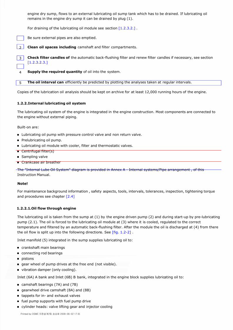
Copies of the lubrication oil analysis should be kept on archive for at least 12,000 running hours of the engine.
1.2.2.Internal lubricating oil system
The lubricating oil system of the engine is integrated in the engine construction. Most components are connected tothe engine without external piping.
Built-on are:
Lubricating oil pump with pressure control valve and non return valve.
Prelubricating oil pump.
Lubricating oil module with cooler, filter and thermostatic valves.
Centrifugal filter(s)
Sampling valve
Crankcase air breather
The "Internal Lube Oil System" diagram is provided in Annex A - Internal systems/Pipe arrangement , of this
Instruction Manual.
Note!
For maintenance background information , safety aspects, tools, intervals, tolerances, inspection, tightening torque
and procedures see chapter [2.4]
1.2.2.1.Oil flow through engine
The lubricating oil is taken from the sump at (1) by the engine driven pump (2) and during start-up by pre-lubricating
pump (2.1). The oil is forced to the lubricating oil module at (3) where it is cooled, regulated to the correct
temperature and filtered by an automatic back-flushing filter. After the module the oil is discharged at (4) from there
the oil flow is split up into the following directions. See [fig. 1.2-2] .
Inlet manifold (5) integrated in the sump supplies lubricating oil to:
crankshaft main bearings
connecting rod bearings
pistons
gear wheel of pump drives at the free end (not visible).
vibration damper (only cooling).
Inlet (6A) A bank and Inlet (6B) B bank, integrated in the engine block supplies lubricating oil to:
camshaft bearings (7A) and (7B)
gearwheel drive camshaft (8A) and (8B)
tappets for in- and exhaust valves
fuel pump supports with fuel pump drive
cylinder heads: valve lifting gear and injector cooling
engine dry sump, flows to an external lubricating oil sump tank which has to be drained. If lubricating oil
remains in the engine dry sump it can be drained by plug (1).
For draining of the lubricating oil module see section [1.2.3.2.] .
Be sure external pipes are also emptied.
2 Clean oil spaces including camshaft and filter compartments.
3 Check filter candles of the automatic back-flushing filter and renew filter candles if necessary, see section
[1.2.3.2.3.]
4 Supply the required quantity of oil into the system.
5 The oil interval can efficiently be predicted by plotting the analyses taken at regular intervals.
Printed by DSME 의장설계2팀 송승화 2009-06-02 17:30

8/9/2019 W26 Instruction Manual
http://slidepdf.com/reader/full/w26-instruction-manual 28/304
P_0000045
actuator drive (9)
turbocharger bearings (11A) and (11B)
Figure 1.2-2: General overview oil flow through engine
1.2.2.1.1.Oil flow main bearings, connecting rod and pistons
Oil flow main bearing
Lubricating oil in the manifold (5) enters the main bearings through oversized drillings for side studs (12) and main
bearing cap studs (13), see [fig. 1.2-3] . The oil flows into groove (14) of the engine block. The upper main bearing
shell is over a part of the circumference provided of large size holes from where the oil flows to the main bearing andthe crankshaft main bearing journal.
Printed by DSME 의장설계2팀 송승화 2009-06-02 17:30
8/9/2019 W26 Instruction Manual
http://slidepdf.com/reader/full/w26-instruction-manual 29/304
P_0000045
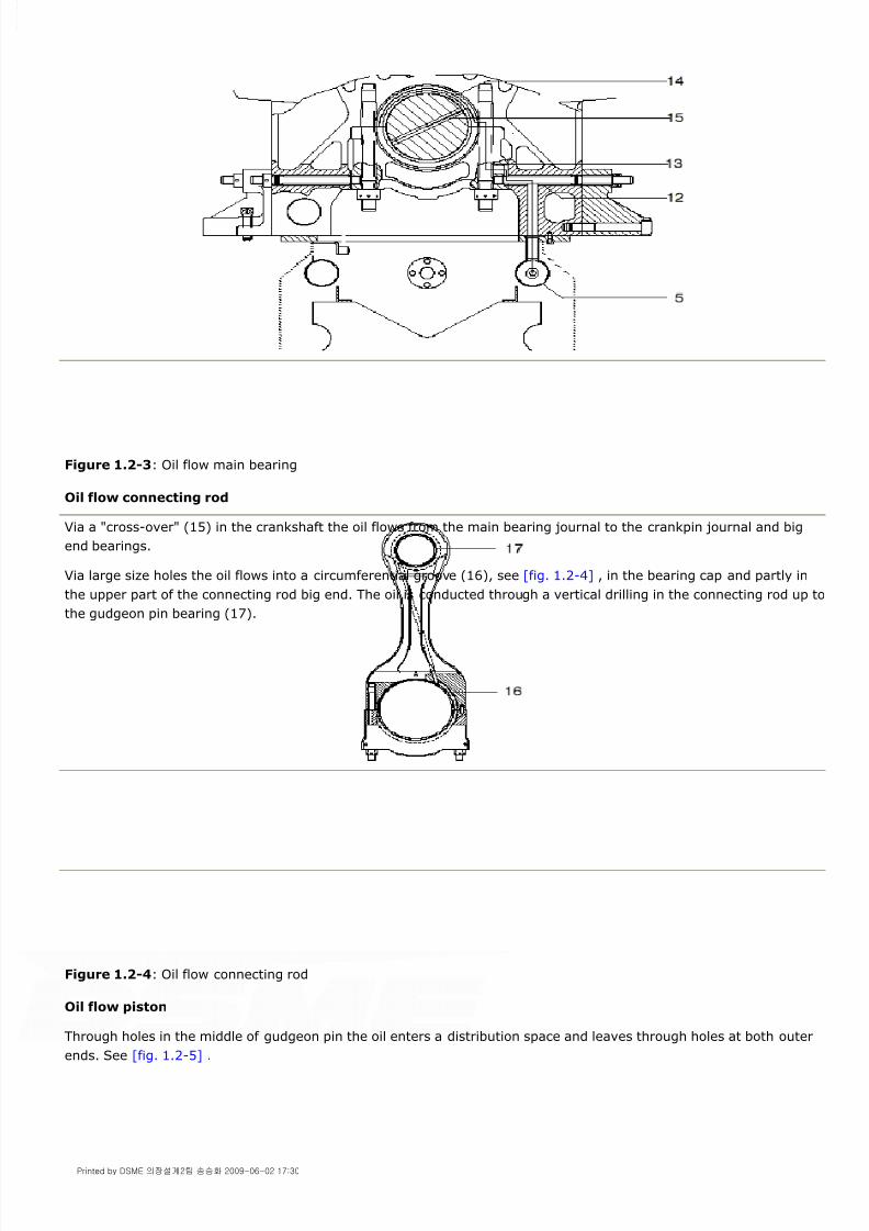
Figure 1.2-3: Oil flow main bearing
Oil flow connecting rod
Via a "cross-over" (15) in the crankshaft the oil flows from the main bearing journal to the crankpin journal and big
end bearings.
Via large size holes the oil flows into a circumferential groove (16), see [fig. 1.2-4] , in the bearing cap and partly in
the upper part of the connecting rod big end. The oil is conducted through a vertical drilling in the connecting rod up to
the gudgeon pin bearing (17).
Figure 1.2-4: Oil flow connecting rod
Oil flow piston
Through holes in the middle of gudgeon pin the oil enters a distribution space and leaves through holes at both outer
ends. See [fig. 1.2-5] .
Printed by DSME 의장설계2팀 송승화 2009-06-02 17:30

8/9/2019 W26 Instruction Manual
http://slidepdf.com/reader/full/w26-instruction-manual 30/304
P_0000045
Figure 1.2-5: Gudgeon pin
Oil is discharged into 4 vertical drillings in the piston skirt (20), see [fig. 1.2-6] . At the end of the vertical drillings the
lubricating oil flow is restricted by orifices (19) to control the quantity of oil for piston crown cooling.
Four spray holes take care of lubrication of liner, piston skirt and piston rings during engine operation. The flows are
restricted by orifices (18). The excess of lubricating oil on the liner is scraped off by a scraper ring and drained via a
groove, below the scraper ring, through holes in piston skirt down into the crank case.
After passing the restrictions in top of the piston skirt the lubricating oil enters the outer space (21) of the piston
crown. The outer space is separated from the center space by a rim in which two horizontal grooves at certain height.
Due to these grooves the outer crown space is always partly filled with oil.
During the up and down stroke of the piston the lubricating oil is shaken and increased in speed, intensively cooling
the piston crown. The displaced oil flows to the center section (22) of the piston crown. A second shaker action takes
place cooling the center of the crown. After cooling down the piston the lubricating oil flows to the engine sump.
Figure 1.2-6: Oil flow piston
1.2.2.1.2.Oil flow gear drive
Part of the lubricating oil flow to the camshaft is branched for lubrication of the intermediate gearing and intermediate
bearings, see [fig. 1.2-7] .
Both gearwheels are provided with 4 radial holes for lubrication of the gearwheel teeth. The outer end of the radial
holes are provided with orifices
Printed by DSME 의장설계2팀 송승화 2009-06-02 17:30
8/9/2019 W26 Instruction Manual
http://slidepdf.com/reader/full/w26-instruction-manual 31/304
P_0000045
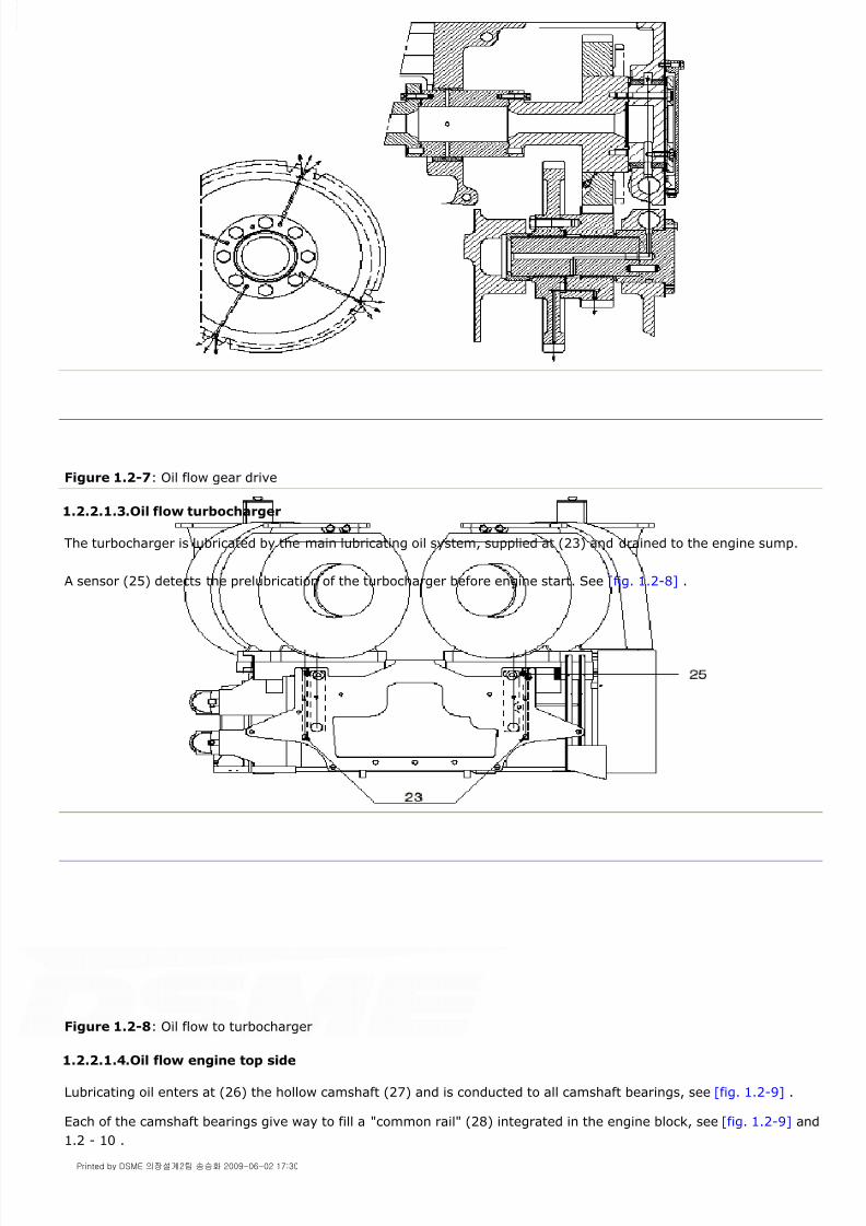
Figure 1.2-7: Oil flow gear drive
1.2.2.1.3.Oil flow turbocharger
The turbocharger is lubricated by the main lubricating oil system, supplied at (23) and drained to the engine sump.
A sensor (25) detects the prelubrication of the turbocharger before engine start. See [fig. 1.2-8] .
Figure 1.2-8: Oil flow to turbocharger
1.2.2.1.4.Oil flow engine top side
Lubricating oil enters at (26) the hollow camshaft (27) and is conducted to all camshaft bearings, see [fig. 1.2-9] .
Each of the camshaft bearings give way to fill a "common rail" (28) integrated in the engine block, see [fig. 1.2-9] and
1.2 - 10 .
Printed by DSME 의장설계2팀 송승화 2009-06-02 17:30

8/9/2019 W26 Instruction Manual
http://slidepdf.com/reader/full/w26-instruction-manual 32/304
P_0000045
Figure 1.2-9: Oil flow through camshaft
From this common rail the lubricating oil is supplied to the HP fuel pump tappet (29) and to the inlet- and exhaust
valve drive tappets (30).
To provide cylinder head components with oil, a lubricating oil pipe is mounted between connection (31), see
[fig. 1.2-10] and connection (32), see [fig. 1.2-11] .
Figure 1.2-10: Oil flow HP fuel pump drive and valve drive
Part of the oil is used for cooling the nozzle tip of the fuel injector (33), see [fig. 1.2-11] . The lubricated components
are; rocker arms and shaft (34); pivots for push rod (35) and bridge piece (36); valve rotators (37); valves (38) and
valve guides (39).
Figure 1.2-11: Oil flow cylinder head
1.2.2.1.5.Oil flow actuator drive
Part of the lubricating oil from oil supply line (40) is supplied to the actuator drive (41), see [fig. 1.2-12] .
Printed by DSME 의장설계2팀 송승화 2009-06-02 17:30

8/9/2019 W26 Instruction Manual
http://slidepdf.com/reader/full/w26-instruction-manual 33/304
P_0000045
Figure 1.2-12: Lubricating oil for actuator drive
1.2.3.Components of internal system
1.2.3.1.Lubricating oil pump
The engine driven lubricating oil pump (1) is of sufficient capacity to maintain the nominal lubricating oil pressure at
engine operating conditions. During start-up the engine driven lubricating oil pump has to be supported by a
prelubricating oil pump till minimum engine rpm is obtained.
The junction box (2) built-on the discharge of the engine driven lubricating oil pump is provided with a non return
valve to avoid reverse flow of the lubricating oil in case a prelubricating pump or a stand-by pump is operated.
The pressure control unit (3) is built-on the junction box, for description and maintenance see section [1.2.3.1.1.]
Figure 1.2-13: Lubricating oil pump
Removing pump from engine
1 Remove pipe sections connected to the lubricating oil pump.
2 Remove pressure control unit (3).
3 Remove junction box (2).
Printed by DSME 의장설계2팀 송승화 2009-06-02 17:30

8/9/2019 W26 Instruction Manual
http://slidepdf.com/reader/full/w26-instruction-manual 34/304
P_0000045
Figure 1.2-14: Derrick for free end side mounted pumps
Disassembling pump
Figure 1.2-15: Lubricating oil pump, cross section
Pump inspection and assembling
4 Install tool [9612ZT937] against the bottom side of the charge air cooler with four bolts, see [fig. 1.2-14] .
Use position 'B' for removal of the lubricating oil pump (6) and position 'A' for removal of HT cooling water pump
(7) and LT cooling water pump (8).
5 Remove all bolts (5), see [fig. 1.2-13] .
6 Take lubricating oil pump (6) from engine by tool [9612ZT937] and sling, see [fig. 1.2-14] .
7 Remove gear wheel (9) by removing the tapbolts (10) and gland (11). By knocking on the wheel hub the
tapered rings (12) will come loose, see [fig. 1.2-15] .
Take gear wheel from the shaft.
8 Remove both pump covers and the shafts out of the pump housing.
Printed by DSME 의장설계2팀 송승화 2009-06-02 17:30
8/9/2019 W26 Instruction Manual
http://slidepdf.com/reader/full/w26-instruction-manual 35/304
P_0000045
Note!
Mind the correct position of clamping rings.
Mounting pump on engine
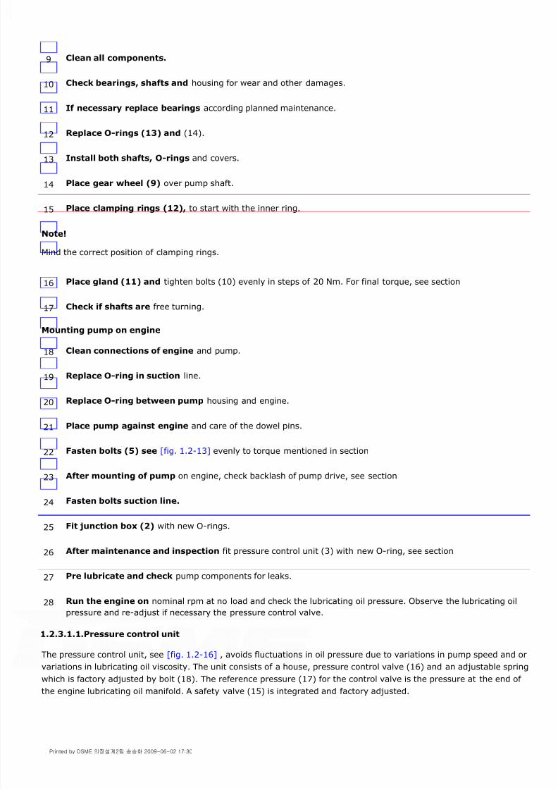
1.2.3.1.1.Pressure control unit
The pressure control unit, see [fig. 1.2-16] , avoids fluctuations in oil pressure due to variations in pump speed and or
variations in lubricating oil viscosity. The unit consists of a house, pressure control valve (16) and an adjustable springwhich is factory adjusted by bolt (18). The reference pressure (17) for the control valve is the pressure at the end of
the engine lubricating oil manifold. A safety valve (15) is integrated and factory adjusted.
9 Clean all components.
10 Check bearings, shafts and housing for wear and other damages.
11 If necessary replace bearings according planned maintenance.
12 Replace O-rings (13) and (14).
13 Install both shafts, O-rings and covers.
14 Place gear wheel (9) over pump shaft.
15 Place clamping rings (12), to start with the inner ring.
16 Place gland (11) and tighten bolts (10) evenly in steps of 20 Nm. For final torque, see section
17 Check if shafts are free turning.
18 Clean connections of engine and pump.
19 Replace O-ring in suction line.
20 Replace O-ring between pump housing and engine.
21 Place pump against engine and care of the dowel pins.
22 Fasten bolts (5) see [fig. 1.2-13] evenly to torque mentioned in section
23 After mounting of pump on engine, check backlash of pump drive, see section
24 Fasten bolts suction line.
25 Fit junction box (2) with new O-rings.
26 After maintenance and inspection fit pressure control unit (3) with new O-ring, see section
27 Pre lubricate and check pump components for leaks.
28 Run the engine on nominal rpm at no load and check the lubricating oil pressure. Observe the lubricating oil
pressure and re-adjust if necessary the pressure control valve.
Printed by DSME 의장설계2팀 송승화 2009-06-02 17:30

8/9/2019 W26 Instruction Manual
http://slidepdf.com/reader/full/w26-instruction-manual 36/304
P_0000045
Figure 1.2-16: Pressure control and safety valve
Maintenance
1.2.3.2.Lubricating oil module
The lubricating oil module is mounted on the driving end of the engine and consists of the oilcooler (1), thermostatic
valves (2) and the automatic back-flushing oil filter (3), see [fig. 1.2-17] .
Figure 1.2-17: Lubricating oil module
1.2.3.2.1.Lubricating oil cooler
1 Measure and note measurement 'X', see
2 Remove pressure control valve (16) and safety valve (15).
3 Clean all parts of the unit and check for wear. Replace worn or damaged parts.
4 Check if pressure control valve moves easily in the unit.
5 Renew O-ring and other sealing rings. Fit all parts back in the unit.
6 Make sure measurement 'X' is the same as measured before maintenance, see
Printed by DSME 의장설계2팀 송승화 2009-06-02 17:30
8/9/2019 W26 Instruction Manual
http://slidepdf.com/reader/full/w26-instruction-manual 37/304
P_0000045
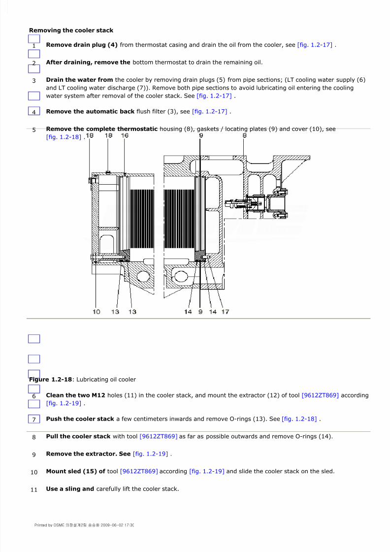
Removing the cooler stack
Figure 1.2-18: Lubricating oil cooler
1 Remove drain plug (4) from thermostat casing and drain the oil from the cooler, see [fig. 1.2-17] .
2 After draining, remove the bottom thermostat to drain the remaining oil.
3 Drain the water from the cooler by removing drain plugs (5) from pipe sections; (LT cooling water supply (6)
and LT cooling water discharge (7)). Remove both pipe sections to avoid lubricating oil entering the cooling
water system after removal of the cooler stack. See [fig. 1.2-17] .
4 Remove the automatic back flush filter (3), see [fig. 1.2-17] .
5 Remove the complete thermostatic housing (8), gaskets / locating plates (9) and cover (10), see
[fig. 1.2-18] .
6 Clean the two M12 holes (11) in the cooler stack, and mount the extractor (12) of tool [9612ZT869] according
[fig. 1.2-19] .
7 Push the cooler stack a few centimeters inwards and remove O-rings (13). See [fig. 1.2-18] .
8 Pull the cooler stack with tool [9612ZT869] as far as possible outwards and remove O-rings (14).
9 Remove the extractor. See [fig. 1.2-19] .
10 Mount sled (15) of tool [9612ZT869] according [fig. 1.2-19] and slide the cooler stack on the sled.
11 Use a sling and carefully lift the cooler stack.
Printed by DSME 의장설계2팀 송승화 2009-06-02 17:30
8/9/2019 W26 Instruction Manual
http://slidepdf.com/reader/full/w26-instruction-manual 38/304
P_0000045
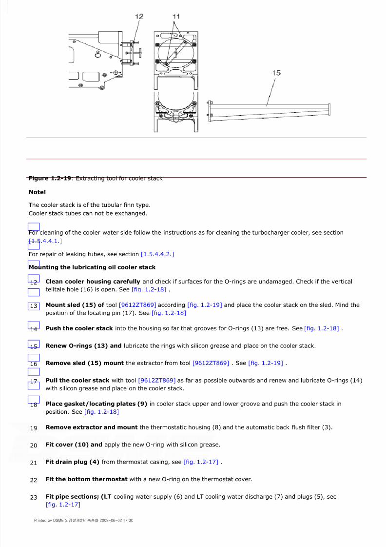
Figure 1.2-19: Extracting tool for cooler stack
Note!
The cooler stack is of the tubular finn type.
Cooler stack tubes can not be exchanged.
For cleaning of the cooler water side follow the instructions as for cleaning the turbocharger cooler, see section
[1.5.4.4.1.]
For repair of leaking tubes, see section [1.5.4.4.2.]
Mounting the lubricating oil cooler stack
12 Clean cooler housing carefully and check if surfaces for the O-rings are undamaged. Check if the vertical
telltale hole (16) is open. See [fig. 1.2-18] .
13 Mount sled (15) of tool [9612ZT869] according [fig. 1.2-19] and place the cooler stack on the sled. Mind the
position of the locating pin (17). See [fig. 1.2-18]
14 Push the cooler stack into the housing so far that grooves for O-rings (13) are free. See [fig. 1.2-18] .
15 Renew O-rings (13) and lubricate the rings with silicon grease and place on the cooler stack.
16 Remove sled (15) mount the extractor from tool [9612ZT869] . See [fig. 1.2-19] .
17 Pull the cooler stack with tool [9612ZT869] as far as possible outwards and renew and lubricate O-rings (14)
with silicon grease and place on the cooler stack.
18 Place gasket/locating plates (9) in cooler stack upper and lower groove and push the cooler stack in
position. See [fig. 1.2-18]
19 Remove extractor and mount the thermostatic housing (8) and the automatic back flush filter (3).
20 Fit cover (10) and apply the new O-ring with silicon grease.
21 Fit drain plug (4) from thermostat casing, see [fig. 1.2-17] .
22 Fit the bottom thermostat with a new O-ring on the thermostat cover.
23 Fit pipe sections; (LT cooling water supply (6) and LT cooling water discharge (7) and plugs (5), see
[fig. 1.2-17]
Printed by DSME 의장설계2팀 송승화 2009-06-02 17:30

8/9/2019 W26 Instruction Manual
http://slidepdf.com/reader/full/w26-instruction-manual 39/304
P_0000045
Note!
The free distance between gasket / locating plates (9) gives way to oil or water to the outside in case of leaking O-
rings. See [fig. 1.2-18] .
1.2.3.2.2.Thermostatic valves
The lubricating oil temperature is controlled by thermostatic valves (2) to maintain the temperature at engine inlet,
See [fig. 1.2-20] .
Thermostatic valves
Figure 1.2 - 20 shows a thermostatic valve in closed (cold) position. All oil enters the by-pass at (16) and flows via
(17) to the lubricating oil filter. When the thermostatic valve opens oil from the cooler enters at (18) and also flows to
the lubricating oil filter via connection (17).
Figure 1.2-20: Thermostatic valve
Operation
Cooling systems will usually operate at or slightly below or above nominal temperature.
Any system operating at a deviation of 6°C or more from nominal is probably malfunctioning. The cause should be
located and corrected immediately.
Maintenance
It is advised to check periodically the correct working range of the elements. This can be done by slowly heating the
elements in a bucket with water while measuring the water temperature. Replace elements out of range. The nominal
temperature range is mentioned on the elements.
Warning!
Elements exposed to a temperature of more than 10°C above the nominal working range will be damaged and
24 Fill and vent the water part of the lubricating oil cooler by opening plug (18) and vent the cooling water
system.
25 Switch on the pre-lubricating oil pump and check for leaks between locating plates and at the telltale hole at
(16) in [fig. 1.2-18] .
Check the lubricating oil level.
26 Switch off lubricating oil pump and switch on the LT cooling water stand-by pump. Check again for leaks and
check the LT cooling water level.
Printed by DSME 의장설계2팀 송승화 2009-06-02 17:30

8/9/2019 W26 Instruction Manual
http://slidepdf.com/reader/full/w26-instruction-manual 40/304
P_0000045
should be renewed.
Trouble shooting
In the event the cooling system does not operate near to the operating temperature see section [2.3.2.6.1.] for help
to find the problem.
1.2.3.2.3.Automatic back-flushing filter
General
The automatic back-flushing filter (1), see [fig. 1.2-21] is mounted on the lubricating oil cooler housing (2). The filter
works with permanent back-flushing using its own process fluid. No external power is required to operate the
automatic filter.
The solids caught by filter (1) are fed during the continuous back-flushing process to the centrifugal filter via
connection (3).
The back-flushed oil is filtered by the centrifugal filter and flows back into the engine sump via connection (12), see
[fig. 1.2-27] .
Figure 1.2-21: Automatic back-flushing filter
Printed by DSME 의장설계2팀 송승화 2009-06-02 17:30

8/9/2019 W26 Instruction Manual
http://slidepdf.com/reader/full/w26-instruction-manual 41/304
P_0000045
Figure 1.2-22: Automatic back-flushing filter (Filtration phase)
Filtration phase
The oil to be filtered enters through inlet (11) and passes the turbine (35). The turbine drives the rotating flushing
arm (41). After the turbine the oil enters the filter candles (36) at both ends. Direct at the right side and via the
central connection tube (37) at the left side. The oil flows from the inside to the outside leaving most of the dirt
particles behind at the inside of the filter candles (36).
The fluid filtered in this way now passes through the protective filter (38) to the filter outlet (12).
Figure 1.2-23: Automatic back-flushing filter (Back-flushing phase)
Back-flushing phase
The oil flow energy drives the turbine (35) installed in the inlet flange (11). The high speed of the turbine (35) is
reduced by the worm gear unit (39) and gear (40) to the lower speed required for turning the flushing arm (41).
The individual filter candles (36) are now connected successively via the continuously rotating flushing arm (41) to the
flushing bush (42).
Printed by DSME 의장설계2팀 송승화 2009-06-02 17:30

8/9/2019 W26 Instruction Manual
http://slidepdf.com/reader/full/w26-instruction-manual 42/304
P_0000045
The lower pressure in the interior of the filter candles (36) during the back-flushing operation and the higher pressure
outside the filter candles (36) produce a counter-flow through the mesh from the clean filter side via the dirty filter
side to the centrifugal filter via connection (34), see [fig, 1.2-23] .
The counter-flow together with the cross-flow (unfiltered oil entering the top side of the filter candles (36)) result in an
efficient cleaning action.
The rotary motion of the flushing facility can be seen at the visible shaft end (43) in the left filter cover (48).
Figure 1.2-24: Automatic back-flushing filter (Overflow valves)
Functioning of the overflow valves
Should for any reason the filter candles (36) (first filter stage) no longer be adequately cleaned, the overflow valves
(44) are opened at a differential pressure of 2 bar upwards and all the fluid is filtered through the protective filter (38)
(second filter stage).
However, before this situation arises, it is given a differential pressure warning (remote control). The cause must now
be localised and remedied.
If this warning is ignored, an alarm is emitted by the second contact of the differential pressure indicator.
Note!
The filter may only be operated in this emergency condition for a short time (opened overflow valves and differential
pressure warning). Prolonged operation in this mode can result in damage to engine components.
The overflow valves are closed under normal operating conditions, even during start-up at lower fluid temperatures.
Printed by DSME 의장설계2팀 송승화 2009-06-02 17:30

8/9/2019 W26 Instruction Manual
http://slidepdf.com/reader/full/w26-instruction-manual 43/304
P_0000045
Figure 1.2-25: Automatic back-flushing filter (Maintenance)
Maintenance
Even with automatic filters inspections and maintenance must be performed at regular intervals.
It is important to remember that in spite of constant back-flushing the mesh may become clogged over the course of
time, depending on the quality of the fluid.
In order to maintain trouble-free operation, the following aspects are to be observed during maintenance:
Note!
Should a higher differential pressure occur beforehand, all the filter candles (36) and the protective filter (38) must
be checked and, if necessary, cleaned.
See also section "filter candle inspection and cleaning".
Warning!
A highly contaminated protective filter (38) is a sign of prolonged operation with defective or clogged filter candles
(36) and thus opened overflow valves (44), see fig.1.2 - 24 .
It is necessary to check these components.
Note!
To check this the cover (45) must be removed. Now check the ease of movement with a suitable spanner on the
hexagon of the worm gear unit (46), see [fig. 1.2-25] .If movement is sluggish, refer to section "Sources of faults and their remedy".
Note!
1 The filter must be switched off for all maintenance work.
2 Check filter and connections for leaks.
3 Conduct visual inspection of all filter candles (36) once a year.
4 Check the ease of movement of the turbine (35), the worm gear unit (39), including gear (40) with flushing
arm (41).
5 It is recommended to replace the filter candles (36) after 2 years.
Printed by DSME 의장설계2팀 송승화 2009-06-02 17:30

8/9/2019 W26 Instruction Manual
http://slidepdf.com/reader/full/w26-instruction-manual 44/304
P_0000045
Longer use is also possible if the filter candles (36) are checked carefully.
It is advisable to replace all static seals during an overhaul.
Filter candle inspection and cleaning
Note!
Make sure that the exposed gear (40) is not damaged.
Note!
It must be ensured that the filter candles are cleaned at a pressure of max. 60 bar and at a minimum distance of the
cleaning nozzle of 20 cm. Otherwise, damage to the mesh is possible.
Note!
Defective filter candles (36) must not be used again.
Note!
Before installation of the entire filter element, the ease of motion of the flushing facility must be checked. The
flushing arm (41) must not grind against the bottom filter plate (50)
1.2.3.2.4.Trouble shooting automatic back-flushing filter
Sources of faults and their remedy
6 Replace the dynamic loaded seals (47), see fig.1.2 - 23 when required.
7 Drain the filter with the drain screw.
8 Remove the left cover (48). see fig.1.2 - 23 .
9 Pull the entire filter element including flushing arm (41) and gear (40) out of the housing.
10 Remove the upper cover plate (49).
11 The filter candles (36) can now be pushed out from below or pulled out from above.
12 Place the filter candles (36) in a cold cleaner e.g. Boll clean 2000, max. soaking time 24 hours.
13 After immersing the filter candles (36), clean them from the outside inwards using high pressure.
14 Before the filter candles (36) are installed, they must be visually inspected and damaged candles replaced bynew ones.
15 Now push the entire filter element into the housing.
By slightly turning the flushing shaft (43), the gear (40) is forced into the drive pinion of the gear unit (39).
16 Re-assemble the filter in the reverse sequence.
Cause of fault: Dp rises Reasons
1. - Viscosity too high - Wait for normal operating conditions
2. - High volume of dirt - Check by-pass treatment unit for functioning
3. - Filter candles clogged - Clean candles
4. - Flushing volume too low - Check flow control device in outlet andsludge discharge line for clogging
Printed by DSME 의장설계2팀 송승화 2009-06-02 17:30
8/9/2019 W26 Instruction Manual
http://slidepdf.com/reader/full/w26-instruction-manual 45/304
P_0000045
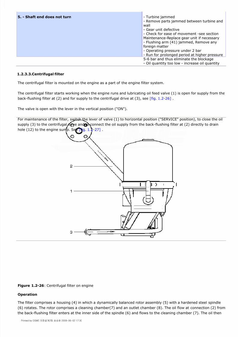
1.2.3.3.Centrifugal filter
The centrifugal filter is mounted on the engine as a part of the engine filter system.
The centrifugal filter starts working when the engine runs and lubricating oil feed valve (1) is open for supply from the
back-flushing filter at (2) and for supply to the centrifugal drive at (3), see [fig. 1.2-26] .
The valve is open with the lever in the vertical position ("ON").
For maintenance of the filter, switch the lever of valve (1) to horizontal position ("SERVICE" position), to close the oil
supply (3) to the centrifugal drive and to connect the oil supply from the back-flushing filter at (2) directly to drain
hole (12) to the engine sump. See [fig. 1.2-27] .
Figure 1.2-26: Centrifugal filter on engine
Operation
The filter comprises a housing (4) in which a dynamically balanced rotor assembly (5) with a hardened steel spindle
(6) rotates. The rotor comprises a cleaning chamber(7) and an outlet chamber (8). The oil flow at connection (2) from
the back-flushing filter enters at the inner side of the spindle (6) and flows to the cleaning chamber (7). The oil then
5. - Shaft end does not turn - Turbine jammed- Remove parts jammed between turbine andwall- Gear unit defective- Check for ease of movement -see sectionMaintenance-Replace gear unit if necessary- Flushing arm (41) jammed, Remove anyforeign matter- Operating pressure under 2 bar- Run for prolonged period at higher pressure5-6 bar and thus eliminate the blockage- Oil quantity too low - increase oil quantity
Printed by DSME 의장설계2팀 송승화 2009-06-02 17:30

8/9/2019 W26 Instruction Manual
http://slidepdf.com/reader/full/w26-instruction-manual 46/304
P_0000045
passes from the cleaning chamber to the outlet chamber (8) with outlet holes (9) at the lower part of the rotor.
Figure 1.2-27: Centrifugal filter
Centrifugal filter cleaning
Note!
The rotor assembly should be removed with care in order not to damage the lower bearing, Pelton wheel and jet
pipes.
Note!
For easy removal of dirt in the rotor unit use a paper insert.
For the part number of the insert see the parts catalogue.
If the filter has reached the maximum dirt deposit layer thickness of 25mm within the recommended cleaning interval
(weekly), it is necessary to clean the filter more frequently.
1 Close the oil supply to the centrifugal filter by switching the lever of valve (1) to the horizontal position, see
[fig. 1.2-26] .
2 Wait a few minutes to be sure that the centrifuge has come to a complete stop and to allow the oil to drain to
the sump
3 Loosen the cover clamp (13), remove filter cover (14) and rotor assembly carefully, see [fig. 1.2-27] .
4 Hold the rotor body and remove the rotor cover nut (16). Remove the rotor cover (15) and the rotor wall
from the rotor bottom.
5 Clean the parts of the rotor assembly and the filter housing (4). Ensure that all rotor components are
thoroughly cleaned and free from dirt deposits.
6 Clean the jet pipe outlets (10) of the rotor drive with compressed air.
7 Examine the lower bearing in the filter housing and the ball bearing in the filter cover (14) to ensure they are
free from damage or excessive wear. Examine the O-rings for damage. Renew if necessary.
Printed by DSME 의장설계2팀 송승화 2009-06-02 17:30

8/9/2019 W26 Instruction Manual
http://slidepdf.com/reader/full/w26-instruction-manual 47/304
P_0000045
1.2.3.4.Lubricating oil sampling valve
[Fig. 1.2-28] shows the position of the lubricating oil sampling valve (1) on the engine. Take the lubricating oilsamples according the instructions in section [1.2.1.3.]
Figure 1.2-28: Location of lubricating oil sampling valve
1.2.4.Crankcase breathing system
The function of the crankcase breather is to avoid overpressure in the crankcase caused by blow-by of the piston rings
and/or bad functioning turbocharger sealings.
The crankcase breather consists of a housing (1), containing a horizontally positioned plate valve (2), see
.
Any crankcase over pressure is released via the plate valve and the vent pipe (3).
Inspect proper functioning of the system periodically during engine operation. The free end of the vent pipe should be
8 Fit a new paper insert into the rotor body and reassemble the rotor in opposite order. Use silicone grease for
the O-rings.
9 Tighten nut (16) with a torque of 20 Nm(or hand tight +1/3 of a turn).
10 Replace the rotor assembly ensuring spindle (6) slides smoothly into the lower bearing and the Pelton wheel
and jet pipe assembly are not damaged.
11 Check if the rotor unit (5) rotates easily.
12 Slide the filter cover (14) together with the ball bearing onto spindle (6) and down onto the locating ring of
the filter housing. Fit the clamp (13) and tighten the cover to the housing. (Torque of the clamp bolts is 6-8
Nm)
13 Open the oil supply to the filter by switching the lever of valve (1) to the vertical position, see [fig. 1.2-26] .
14 Check during running of the engine for leaks and check if the rotor is rotating.
Printed by DSME 의장설계2팀 송승화 2009-06-02 17:30

8/9/2019 W26 Instruction Manual
http://slidepdf.com/reader/full/w26-instruction-manual 48/304
P_0000045
covered by an anti flame gauze. Clean this gauze periodically to avoid crankcase over pressure.
A part of the crankcase gases consists of water vapour that, in contact with the relative colder vent pipe, will
condensate. Condensate runs down and is collected at the bottom of the breather and drained at connection (4), see
[fig. 1.2-29] .
Figure 1.2-29: Crankcase breather and vent pipe
The drained condensate via connection (4) during "normal" engine operation at certain load is a fixed amount. Check
this quantity daily. An increased quantity of condensate might indicate e.g.:
more gas blow-by by possible worn or sticked piston rings water in the crankcase caused by a leaking O-rings.
bad functioning turbocharger sealings.
Note!
Excessive smoke from crankcase breather might indicate that a hot spot is vaporizing lubricating oil and may lead to
a crankcase explosion.
Printed by DSME 의장설계2팀 송승화 2009-06-02 17:30

8/9/2019 W26 Instruction Manual
http://slidepdf.com/reader/full/w26-instruction-manual 49/304
P_0000045
1.3.1.General
The start of an engine requires a large amount of air under high pressure for a relatively brief period. To meet this
demand it is necessary to provide a system for compressed air stored in vessels until needed.
The starting air system should consist of an air compressor driven by an electric motor, air vessel(s), pressure gauge,
relief valve, piping to the engine and a compressed air supply valve located near the engine.
Normally, the minimum compressor capacity should be sufficient to replenish the starting air for the largest unit in one
hour after such supply has been reduced to the minimum pressure necessary to start the engine.
The total air vessel volume depends on the air storage pressure, the number of starts required before recharging the
vessels, the number of engines in the installation and the starting air requirements for the largest engine.
At least two vessels should be available in each installation to insure that starting air pressure is always available even
if a vessel is out of service for any reason.
The compressed air system should be free of condensation and the most effective way to prevent condensation
occurring in a compressed air line is to ensure that the air has a dew-point below the temperature to which any part of
the system will be exposed for an appreciable period of time. This can be achieved by appropriated components.
Water in compressed air systems can give rise to one or several of the following indirect costs:
water damage to instrumentation and compressed air starter motor.
rusting of pipework which will lead to leaking traps, joints and solenoids etc.
clogging of hygroscopic materials.
1.3.2.Start stop system
Engine start process
The engine is started by compressed air for driving the compressed air starter motor(s) ( max. 30 bar and min. 15
bar), see [fig. 1.3-1] .
On a signal to start the engine:
Start solenoid valve (01) is activated electrically,
Admitting throttled air to rotate the starter motor slowly while connecting the bendix 'L' to the gear ring on theflywheel.
after the bendix is engaged, valve 'F' opens the air supply to switch valve 'H' into open position, supplying full airpessure to the starter motor 'K'.
the starter motor 'K' starts to rotate the engine.
At the moment the engine fires, solenoid valve (01) is de-energized, valve 'F' is depressurized and the main startingvalve 'H' is closed. The air supply to the compressed air starter motor stops.
1.3.Starting Air System 1.3-PAAE062665-00
Printed by DSME 의장설계2팀 송승화 2009-06-02 17:31

8/9/2019 W26 Instruction Manual
http://slidepdf.com/reader/full/w26-instruction-manual 50/304
P_0000045
Figure 1.3-1: Start system diagram ( principle working )
The "Internal Start/Stop Air System" diagram is provided in Annex A - Internal systems/Pipe arrangement , of this
Instruction Manual.
Emergency engine start
The start solenoid valve is provided with an emergency start push button. For the emergency start procedure see
section [2.3.1.7.]
Warning!
Be aware that all safety devices are overruled if the engine is started by using the emergency start push button.
Engine stop
When the engine has to be stopped by the operator or by the protecting system, solenoid (7) is activated admitting air
(30 bar) to the stop cylinders (5) mounted on the HP fuel pump racks, see [fig. 1.6-5] and 1.3 - 2 .
Air bottle (4) contains sufficient control air to stop the engine in case of too low control air pressure in the main supply
line.
For the control and safety system, see chapter [1.6.]
Printed by DSME 의장설계2팀 송승화 2009-06-02 17:31

8/9/2019 W26 Instruction Manual
http://slidepdf.com/reader/full/w26-instruction-manual 51/304
P_0000045
Figure 1.3-2: Pneumatic stop system
1.3.3.Compressed air starter motor
1.3.3.1.General
The compressed air starter motor has two spur gears (rotors). All distribution valves are inside the motor body.
The problem of high torques to be transmitted has been solved by means of a direct mechanical transmission without
clutch or free wheel, and the driving pinion, thus engages directly and smoothly with the flywheel gear ring. The helix,
carrying the pinion, is supported by the motor body.
Air starters can be operated manually or remote.
Although starters are designed to work at a pressure of 30 bar they can operate also at lower pressures.
An electrically start interlock and a pneumatically start interlock prevent running of the compressed air starter motor
in case the turning gear is engaged.
1.3.3.2.Description of compressed air starter motor
Control circuit
After opening the starting air vessels, air is admitted into duct (1), and via tubes (2) and (3), to start solenoid valve
(4), see [fig. 1.3-3] .
By manually or remote operating valve (4), the valve stem closes orifice (5) and air passes tube (6) operating piston
(7). Piston (7) opens valve (8) closing at the same time orifice (9) which is connected to the atmosphere. Air from
duct (1), via tube (2), charges channel (10).
Printed by DSME 의장설계2팀 송승화 2009-06-02 17:31

8/9/2019 W26 Instruction Manual
http://slidepdf.com/reader/full/w26-instruction-manual 52/304
P_0000045
Figure 1.3-3: Compressed air starter motor disengaged
Pre-engagement
Air in channel (10) and channel (12), passing the check valve-orifice (13), is filling ducting (14), see [fig. 1.3-4] . A
small flow of air is now driving the rotary motor (15) in a slow motion.
By means of shaft (16), engaged with internal gear (17), the rotary motor transmits an even more reduced rotating
movement through helix (18) to shaft (19) and so the driving pinion (20). Simultaneously, air in channel (10) pushes
piston (11) and shaft (19) outwards against the spring force (22).
Due to this axial displacement and slow motion of the rotary motor (15), driving pinion (20) is gentle engaged, with
the additional help of helix (18), into the gear ring (23) of the engine flywheel.
Figure 1.3-4: Engaging process compressed air starter motor
Start
When the driving pinion (20) is fully engaged, piston (11) is displaced which opens gate (25) for air to piston (26), see
fig.1.3 - 5 . Piston (26) operates the main air valve (27).
Starting air, from duct (1) into duct (14), starts driving the rotary motor with increasing speed. The diesel engine
accelerates in speed up to firing speed. The starting air, after passing the rotary motor, is exhausted at (30), see
[fig. 1.3-5] .
Printed by DSME 의장설계2팀 송승화 2009-06-02 17:31

8/9/2019 W26 Instruction Manual
http://slidepdf.com/reader/full/w26-instruction-manual 53/304
P_0000045
Figure 1.3-5: Compressed air starter motor engaged
Stop
Once the engine start is achieved, valve (4) is manually or remotely closed. Air, acting on piston (7), is vented
through tube (6) and orifice (5) to atmosphere, see [fig. 1.3-6] .
As piston (7) is not longer pressurized, valve (8) closes and orifice (9) opens venting the air from channel (10).
Check valve/orifice (13) is closed by pressure in duct (14). Piston (26) is released and main air valve (27) is closing.
Due to the high speed, achieved by rotors (28) and (29) of the rotary motor (15), a vacuum is created in duct (14)
opening check valve-orifice (13). Vacuum in channel (12), (10) and (25) is retracting piston (11), shaft (19) and
pinion (20) disconnecting the compressed air starter motor from the engine flywheel (23).
Figure 1.3-6: Stop process compressed air starter motor
1.3.4.Operating instructions
1.3.4.1.Commissioning and operation
Check the air vessels are charged and the flow valve is open.
Test for air leaks and check the control circuit is not choked.
Purge the starting air vessels and starting air lines from water. Be sure the starting air is always absolutely dry and
Printed by DSME 의장설계2팀 송승화 2009-06-02 17:31

8/9/2019 W26 Instruction Manual
http://slidepdf.com/reader/full/w26-instruction-manual 54/304
P_0000045
clean.
In case of a manual start, operate the push button valve for very short periods only.
Check the compressed air starter motor stops automatically once the engine is running.
1.3.5.Maintenance
1.3.5.1.Complete overhaul
For overhaul send the complete compressed air starter motor to
Wärtsilä Corporation or the nearest Wärtsilä Service Office.
1.3.5.2.Storage
When leaving our works, the compressed air starter motor contains anti corrosion oil to protect the inner parts. In
spite of this, we must recommend storage in a dry place.
1.3.6.Trouble shooting
For pos. numbers see [fig. 1.3-3] up to and included [fig. 1.3-6]
. Action
6. On pressing push-button, starter does not respond and noair flow seems to exist in control circuit.
.
a) Empty air vessel(s). Re-fill vessel(s).
b) Supply valve(s) closed. Open supply valve(s).
c) Control circuit blocked. Disconnect and clean .
7. On pressing push-button, starter does not respond,although air flows through control circuit.
.
a) Leaking control duct. Repair or replace.
b) Insufficient air pressure. Increase pressure in vessel.
c) Piston (7) and valve (8) sticking in closed position. Remove and check both; smoothen guides orchange parts.
d) Push-button stuck. Remove and clean same.
e) Excessive length of main air pipework. Approach push-button to starter or install asolenoid valve near the latter.
8. Pinion revolves and advances, but does not engage the ringgear.
.
a) Ring gear and/or pinion burrs or damage. Clean gear ring and remove burrs
b) Lack of clearance between pinion and ring gear ring. Check for distortion of gear ring and pinion.
9. Pinion revolves but does not advance. .
a) Push-rod (11) inoperative. Disassemble, check, smoothen guide dia-meter; clean or replace if corrosion is visible.
b) Insufficient air pressure. Increase pressure in air vessel.
c) Splined shaft (19) sticking. Disassemble, clean, check spring (22) andreassemble.
d) Excessive length of control pipe. Approach push-button to the starter or installa solenoid valve near the latter.
10. Pinion advances but does not revolve. .
a) Pneumatic motor inoperative. Disassemble, inspect rotors for foreignmatters between teeth and for possible wearof gears, spindles and bearings. Clean andreassemble. Replace worn parts.
b) Check valve (13) stuck or blocked. Disassemble, clean and reassemble.
11. Pinion engages gear ring, but will not turn the engine. .
Printed by DSME 의장설계2팀 송승화 2009-06-02 17:31

8/9/2019 W26 Instruction Manual
http://slidepdf.com/reader/full/w26-instruction-manual 55/304
P_0000045
a) Main valve (26) blocked. Disassemble, clean and reassemble or replacemain valve.
b) Rotors worn or blocked. Disassemble, clean and reassemble or replace
rotors.
c) Insufficient air pressure. Increase pressure in air vessel.
d) Main air pipework restricted or of insufficient bore. Check all pipework and replace it if necessary.
12. Starter starts working after opening the flow valve of thefeed line, although push-button (or solenoid valve ) is notactuated.
.
a) Incorrect connection of control pipes. Connect control pipes as per installationinstructions.
b) Main valve (26) blocked and open. Disassemble, clean, and replace joint ifneeded.
13. Lack of starter power. .
a) Main pipework choked or its bore is less than stipulated for thestarter.
Check entire pipework for correct bore andreplace if incorrect.
b) Insufficient air pressure. Increase pressure in air vessel.
c) Badly worn rotors. Disassemble, replace rotors andreassemble.
14. After starting the engine, pinion tries to re-engage andhits the ring gear which results in damage to both.
.
a) Incorrect bore of main pipework. Check entire pipework for correct bore andreplace if incorrect.
b) Starting period unnecessarily long. Check and adjust timer (if fitted) or pressstarter push-button for shorter period.
c) Idling of main valve (26). Disassemble, clean and reassemble.
15. Starter motor will not stop. .
a) Main valve (26) blocked. Disassemble, clean and reassemble.b) Piston (7) and leak valve (8) defective. Disassemble, clean and reassemble, Replace
if needed.
c) Check valve (13) keeps open or does not seat properly. Disassemble, check for correct closing of theball and that plug presses the valve againstits seat.
d) Seal ring badly fitted. This is a frequent fault after changing themotor bearings. Check for correct position.
e) Incorrect adjustment of controls. Adjust timer (if fitted), or operate push-button for shorter periods.
f) Splined shaft (19) sticking. Disassemble, clean, check spring (22) and
reassemble.
Printed by DSME 의장설계2팀 송승화 2009-06-02 17:31

8/9/2019 W26 Instruction Manual
http://slidepdf.com/reader/full/w26-instruction-manual 56/304
P_0000045
1.4.1.General
To prevent formation of scale and to maintain the highly efficient and uniform heat transfer rate through the engine
liners and cylinder heads, only soft, treated water (cooling water), should be used. Furthermore, water should be free
of corrosive properties. A competent water chemist specialised in closed cooling water circuits or manufacturer of
water treatment chemicals should be consulted for recommendations.
1.4.2.Cooling water
1.4.2.1.General
Cooling water = Make-up water + additives.
Make-up water has to meet certain requirements. Water that normally fulfils these requirements, in order of
preference :
Demineralized water.
Reverse osmosis water.
Distillate, (provided the quality is good, little corrosion products, salts etc.).
Softened and decarbonated water.
Softened water.
Cooling water must be treated with an additive in order to prevent corrosion, scale or other deposits in closed
circulating water systems.
Example of water that normally not fulfils these requirements:
Rainwater has a high oxygen and carbon dioxide content; great risk of corrosion.
Drinking water in many places is practically too hard and may contain considerable quantities of chlorides.
Sea water will cause severe corrosion and deposit formation, even if supplied to the system in small amounts.
Note!
The better the water quality the less additive has to be supplied.
Make-up water must be checked before adding the additive. For requirements see section [1.4.2.2.]
1.4.2.2.Requirements
Make-up water must be checked before adding the additive.
For make-up water quality see table.
1.4.Cooling Water System 1.4-PAAE062665-00
Make-up water quality
Free of any foreign particles, air, gases and within the followingspecification:
Property Unit
Chloride (Cl) [mg/l] max. 80
Sulphate content (S) [mg/l] max. 150
pH [-] min. 6.5
Hardness [° dH] max. 10
Engine cooling water system
Cooling water supply - cooling water loss through evaporation should be compensated by make-up water.- cooling water loss through leakages or otherwise should be compensated by adding fullytreated water.
Printed by DSME 의장설계2팀 송승화 2009-06-02 17:31

8/9/2019 W26 Instruction Manual
http://slidepdf.com/reader/full/w26-instruction-manual 57/304
P_0000045
Note!
Re-use of cooling water provided that the quality is beyond any doubt is highly recommended instead of new. Used
cooling water contains very little oxygen, is environmentally more friendly and needs less correction.
Not re-usable cooling water should be drained and disposed of in an ecologically safe way.
1.4.2.3.Qualities of cooling water additives
General
Use of approved cooling water additives during the warranty period is mandatory and is also strongly recommended
after the warranty period.
Start always with the maximum concentration of additives due to the fact that the concentration of active corrosioninhibitors drops in time.
Approved cooling water additives
For approved cooling water additives and systems please contact Wärtsilä Corporation.
Recommended
Coolant based on
Nitrite - borate - Not to be used with soldered surfaces, aluminium and zinc.
- Toxic.
Limited suitable (see restrictions when mentioned):
Coolant based on
Nitrite (sole) - In combination with borate (pH control)
nitrite performs better.
- Not to be used with soldered surfaces, aluminium and zinc.
- Toxic.
Silicate - Harmless to handle.
- Can protect steel as well as copper and
aluminium.
- Not so efficient.
Molybdate - Harmless to handle.
- Can form undesirable deposits.
Organic - May contain phosphonates, polymers
(like polycarboxylic acid) and azoles (for
Cooling water re-use Cooling water to be drained may be re-used provided that it is collected in a clean tank.
Property Unit
Temperatures and pressure See operating data
Preheating:-Temperature of HT cooling water system before starting: [° C] min. 60
Printed by DSME 의장설계2팀 송승화 2009-06-02 17:31

8/9/2019 W26 Instruction Manual
http://slidepdf.com/reader/full/w26-instruction-manual 58/304
P_0000045
instance tolytriazole).
Not advised
Chromate, Phosphate, Borate (sole) and Zinc.
The use of glycol is not recommended. If however glycol is used an additional de-rating has to be applied. See section
de-rating, 1.0.3.
1.4.2.4.Cooling water control
Check the cooling water quality according the maintenance schedule.
Most suppliers of cooling water additives can provide a test kit for measuring the active corrosion inhibitors.
Note!
With most additives correct dosing is very important. Under dosing of additives causes spot corrosion while overdoses
may cause deposits.
Request the supplier of the treatment product for instructions, procedures, dosage and concentration based on the
applicable make -up water.
1.4.3.Internal cooling water system
1.4.3.1.General
Engine cooling is arranged by two separate cooling water circuits.
The High Temperature circuit and the Low Temperature circuit.
The HT cooling water circuit cools the cylinders and the HT section (first stage) of the charge air cooler.
The LT cooling water circuit cools the LT section (second stage) of the charge air cooler and the lubricating oilcooler.
Most components are connected to the engine without external piping.
Built-on are:
HT and LT thermostatic valves.
HT and LT cooling water pump with non return valves.
Charge air cooler HT and LT section.
Lubricating oil cooler.
Connecting piece for cooling water in and outlet.
Common cooling water venting point.
The "Internal Cooling Water System" diagram is provided in Annex A - Internal systems/Pipe arrangement , of this
Instruction Manual.
Note!
For maintenance background information, safety aspects, tools, intervals, tolerances, inspection, tightening torque
and procedures see chapter [2.4.]
1.4.3.2.Description HT cooling water system
At the suction side (1) of the HT cooling water pump (2) water returning from the engine and water from the external
cooler (16) is mixed in the thermostatic block (3). The cooling water at the correct temperature is forced to (4A) and
(4B); the cooling water inlet channels for A- and B-bank.
1 Follow thoroughly the instructions of the supplier.
2 Record results of tests in the engine log book.
Printed by DSME 의장설계2팀 송승화 2009-06-02 17:31

8/9/2019 W26 Instruction Manual
http://slidepdf.com/reader/full/w26-instruction-manual 59/304
P_0000045
Figure 1.4-1: General flow HT cooling water system
Flow from cylinder liner to cylinder head
The cooling water flows with a relatively low speed from the inlet channel (4) at the bottom of the liners upwards
almost to the top of the liners. At the exhaust side, a recess in the engine block makes it possible to pass the rim
around the liner. Next cooling water flows with increased speed from one side to the other resulting in better cooling
of the liner top side.
After circulating around the liner top side, cooling water is collected at camshaft side in a vertical drilling in top of the
engine block. An interconnecting pipe (11) conducts the cooling water into the cylinder head bottom side, see
[fig. 1.4-2] .
Printed by DSME 의장설계2팀 송승화 2009-06-02 17:31

8/9/2019 W26 Instruction Manual
http://slidepdf.com/reader/full/w26-instruction-manual 60/304
P_0000045
Figure 1.4-2: Interconnection into cylinder head
Cylinder head
The cooling water is forced over the cylinder head bottoms and along the injector sleeves. A part of the cooling water
is forced around both the exhaust valve seats. In a common space in the cylinder head, cooling water is cooling the
exhaust gas ductings. Cooling water is collected at top of the cylinder head at exhaust gas side into the multiduct
(12). After the multiduct water goes to the outlet channel (5A and 5B), see [fig. 1.4-1] .
HT cooling water charge air cooler
The water from the engine main outlet (5A) and (5B) is conducted to the HT section (8) of the charge air cooler (first
stage). See also charge air and exhaust gas system, chapter [1.5.] From the charge air cooler the water is conducted
via (9) and (10) and the thermostatic block (3) to the external cooler (15) or the suction side (1) of the cooling water
pump, see [fig. 1.4-1] .
Thermostatic valves
Relative cold water, returning from the external HT water cooler, is mixed with hot water from the engine outlet by a
thermostatic valve to the correct temperature for the engine inlet. The thermostatic block accommodates the
thermostatic valve for HT and LT cooling water circuits. The upper four thermostats control the engine HT water inlet
temperature to the engine. The lower six thermostats control the engine LT water inlet temperature to the engine. Be
careful when elements of different liquid systems are become mixed up for instance during testing on working range.
Sleeve (1) avoids flow between the two channels and is not provided with a thermostatic valve.
Printed by DSME 의장설계2팀 송승화 2009-06-02 17:31

8/9/2019 W26 Instruction Manual
http://slidepdf.com/reader/full/w26-instruction-manual 61/304
P_0000045
Figure 1.4-3: Location of cooling water thermostatic valves
Operation
Cooling systems will usually operate at or slightly below or above nominal temperature.
Any system operating at a deviation of 6°C or more from nominal is probably malfunctioning. The cause should be
located and corrected immediately.
Trouble shooting
In the event the cooling system does not operate near to the operating temperature see section [2.3.2.6.1.] for help
to find the problem.
1.4.3.2.1.Maintenance thermostatic valves
Check periodically according the maintenance intervals the correct working range of the elements.
Removal / mounting of thermostatic valves
Note!
Be careful not to mix the thermostatic valves of different liquid systems due to the fact that each system has its own
working range.
Warning!
Elements exposed to a temperature of more than 10°C above the nominal working range will be damaged and
1 Drain the cooling water system.
2 Remove thermostat housing (2) and thermostatic valve (3), see
3 Check the element by heating it slowly in water while measuring the water temperature. Check at whichtemperature the valve starts to open. The nominal temperature range is mentioned on the elements.
4 Renew element if damaged or out of range.
5 Renew sealing rings (4), (5) and (7), see
6 Fill the cooling water system and check for leaks .
Printed by DSME 의장설계2팀 송승화 2009-06-02 17:31
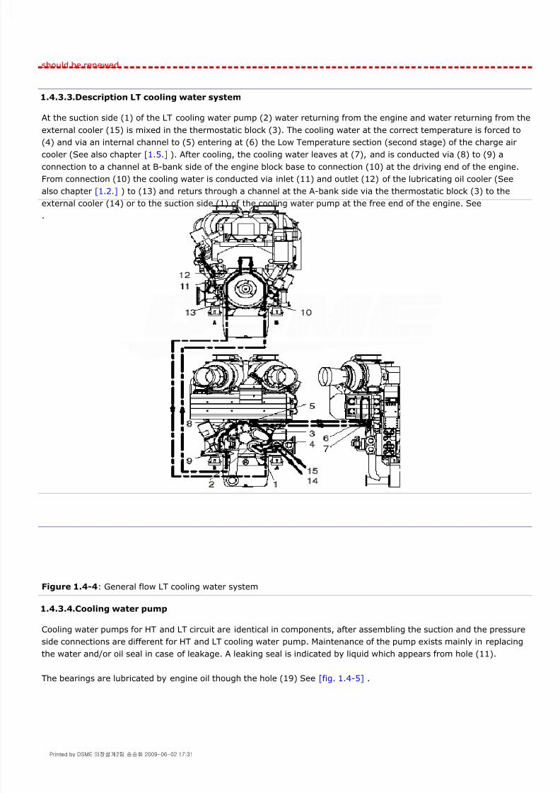
8/9/2019 W26 Instruction Manual
http://slidepdf.com/reader/full/w26-instruction-manual 62/304
P_0000045
should be renewed.
1.4.3.3.Description LT cooling water system
At the suction side (1) of the LT cooling water pump (2) water returning from the engine and water returning from the
external cooler (15) is mixed in the thermostatic block (3). The cooling water at the correct temperature is forced to(4) and via an internal channel to (5) entering at (6) the Low Temperature section (second stage) of the charge air
cooler (See also chapter [1.5.] ). After cooling, the cooling water leaves at (7), and is conducted via (8) to (9) a
connection to a channel at B-bank side of the engine block base to connection (10) at the driving end of the engine.
From connection (10) the cooling water is conducted via inlet (11) and outlet (12) of the lubricating oil cooler (See
also chapter [1.2.] ) to (13) and returs through a channel at the A-bank side via the thermostatic block (3) to the
external cooler (14) or to the suction side (1) of the cooling water pump at the free end of the engine. See
.
Figure 1.4-4: General flow LT cooling water system
1.4.3.4.Cooling water pump
Cooling water pumps for HT and LT circuit are identical in components, after assembling the suction and the pressure
side connections are different for HT and LT cooling water pump. Maintenance of the pump exists mainly in replacing
the water and/or oil seal in case of leakage. A leaking seal is indicated by liquid which appears from hole (11).
The bearings are lubricated by engine oil though the hole (19) See [fig. 1.4-5] .
Printed by DSME 의장설계2팀 송승화 2009-06-02 17:31

8/9/2019 W26 Instruction Manual
http://slidepdf.com/reader/full/w26-instruction-manual 63/304
P_0000045
Figure 1.4-5: Cooling water pump
1.4.3.4.1.Renewal of seals
For the renewal of mechanical water and oil seals it is not necessary to remove the cooling water pump from the
engine.
Removal seals
Mounting seals
1 Drain cooling water and collect for re-use.
2 Remove nuts, spring washers and suction line with impeller cover (1).
3 To remove the impeller (5) loosen all locking bolts (2) a few turns. Remove the bolts adjacent to each
threaded hole in the ring (3) and screw them as jack bolts into these holes pressing off the ring (4).
Remove the impeller and the locking assembly from the pump shaft (13), see [fig. 1.4-5] .
4 Remove the rotating parts of the mechanical water seal set (8A).
5 Remove bolts (6) and slide out seal holder (7).
6 Remove non-rotating ring (8B) of the mechanical seal set and the oil seal (10).
7 Clean all parts carefully and check for wear and damage; replace if necessary.
Printed by DSME 의장설계2팀 송승화 2009-06-02 17:31

8/9/2019 W26 Instruction Manual
http://slidepdf.com/reader/full/w26-instruction-manual 64/304
P_0000045
1.4.3.4.2.Maintenance cooling water pump
Removal pump from engine
8 Clean recess in cooling water pump and clean water circulation hole (12) in seal holder and pump casing.
9 Check tell-tale hole (11) is open and clean.
10 Fit new O-rings (9) with silicon grease on seal holder (7) and fit a new oil seal (10) .
11 Slide seal holder in recess of pump casing. After fully inserting, seal holder outer side should be flat with
pump casing recess.
12 Fit and tighten bolts (6).
13 Press the non-rotating ring of the mechanical seal set (8B) in seal holder (7). Use a plastic pressure piece.
14 Put some liquid soap on the bellows of the rotating part of the mechanical seal set (8A) and slide it on to the
pump shaft until the seal faces touch each other.
15 Place ring (27) over the pump shaft.
16 Prior to installation of the impeller locking assembly clean and slightly oil the contact surfaces of all parts (Do
not use Molybdenum Disulphide). Note that by re-assembling, the threaded holes in ring (3) have to be
positioned opposite undrilled spaces of ring (4) and have to be kept free for disassembling.
17 Place the locking assembly together with the impeller over the pump shaft (13).
18 Keep on pressing ring (3), against the spring pressure of the mechanical seal, as far as possible on to the
pump shaft while tightening the bolts evenly and crosswise in two ore three steps to the final torque. See
section [2.4.4.]
19 Re-check tightening torque by applying it to all bolts all the way around. When no screw will turn any more,
the assembly is completed.
20 Renew sealing rings of pump cover (1) and place cover with spring washers and nuts. Tighten cover nuts
evenly in steps of 20 Nm. For final torque see section [2.4.4.]
1 Drain cooling water and collect for re-use.
2 Remove nuts, spring washers and suction line with impeller cover.
3 If applicable remove cooling water supply at 'X', see [fig. 1.4-5] .
4 Keep the pump against the engine while removing the nuts (14).
5 Install lifting tool [9612ZT937] against the bottom side of the charge air cooler with four bolts, see
[fig. 1.4-6] .
Printed by DSME 의장설계2팀 송승화 2009-06-02 17:31

8/9/2019 W26 Instruction Manual
http://slidepdf.com/reader/full/w26-instruction-manual 65/304
P_0000045
Figure 1.4-6: Lifting tool for pumps
Removal gear wheel and pump shaft
Figure 1.4-7: Pump shaft
Pump inspection and assembling
6 Remove sealings as described in section
7 To remove the gear wheel (18) loosen all locking bolts (15) a few turns. Remove the bolts adjacent to each
threaded hole in the ring (16) and screw them as jack bolts into these holes pressing off the ring (17). The
connection is then released and the locking assembly can be taken out of the gear wheel hub.
Remove the gear wheel from the pump shaft (13), see [fig. 1.4-5] .
8 Apply slight force to push pump shaft (13) out of bearing bracket.
9 Bend lip of locking ring (19) backwards. Loose and remove locking nut (20), see [fig. 1.4-7] .
10 Heat inner race (21) of roller bearing and remove the ring from pump shaft (13).
11 Heat ball bearing (22) and remove ball bearing from pump shaft (13).
12 Remove circlip (23) and roller bearing outer race (24) with roller bearing, out of bearing bracket. See
[fig. 1.4-5] .
13 Clean all parts carefully.
14 Check bearing and shaft clearances.
Printed by DSME 의장설계2팀 송승화 2009-06-02 17:31

8/9/2019 W26 Instruction Manual
http://slidepdf.com/reader/full/w26-instruction-manual 66/304
P_0000045
1.4.3.5.Flexible pipe connections
Some pipe connections are made flexible by the application of a "metal-grip-coupling". To apply the "metal-grip-
coupling" the pipe ends should be well in line and lateral within 1% of the pipe diameter.
Fitting instructions
15 Inspect parts for cavitation, scoring and other possible damage.
16 Replace all wearing parts (bearings, oil seal, mechanical seal, O-rings).
17 Heat ball bearing (22) to 80°C and shrink it on pump shaft (13).
Fit locking ring (19) and turn on locking nut (20) on pump shaft (13).
Secure locking nut (20) by bending over a lip of locking ring (19).
18 Heat inner race of roller bearing (21) to 80°C and shrink the race on pump shaft (13), see [fig. 1.4-7] .
19 Mount outer race of roller bearing (24) and circlip (23) in bearing bracket, see [fig. 1.4-5] .
20 Mount sub-assembled pump shaft and inner race of roller bearing (21) see [fig. 1.4-7] , in the cooling water
pump housing.
21 Check if the shaft is free spinning.
22 Assemble mechanical seals as described in section [1.4.3.4.1.] - Mounting seals: points 2 up to and
including 13.
23 Prior to installation of the gear wheel locking assembly, clean and slightly oil the contact surfaces of all parts
(Do not use Molybdenum Disulphide). Note that by re-assembling, the threaded holes in ring (3) have to be
positioned opposite undrilled spaces of ring (4) and have to be kept free for disassembling.
24 Place the locking assembly together with the gear wheel (18) over the pump shaft (13).
25 Tighten the locking bolts (15) lightly and slide gear wheel (18) to its position on the pump shaft (13), see
[fig. 1.4-5] . Hold the gear wheel in position while tightening the bolts evenly and crosswise in two ore three
steps to the final torque. See section [2.4.4.]
26 Re-check tightening torque by applying it to all bolts all the way around. When no screw will turn any more,
the assembly is completed.
27 Fit new O-rings (25), and (26) with silicon grease on pump casing.
28 Use tool [9612ZT937] to lift pump casing to engine block.
29 Fit and tighten nuts (14), see [fig, 1.4-6] , evenly in steps of 40 Nm to torque setting as mentioned in section
[2.4.4.]
30 Renew sealing rings of pump cover (1), see [fig. 1.4-5] and place cover with spring washers and nuts.
Tighten cover nuts evenly in steps of 20 Nm. For final torque see section [2.4.4.]
31 Check the presence of backlash by opening the cover next to the pump. See section [2.4.5.] [fig. 2.4-32] .
32 Pipe connections to pump casings must be stress free. Tighten flange bolts evenly and cross wise.
1 Remove sharp edges and burrs.
2 Clean pipe where coupling mounts. Eliminate such as scratches, cracks, remove rust, paint and other
coatings,
Printed by DSME 의장설계2팀 송승화 2009-06-02 17:31

8/9/2019 W26 Instruction Manual
http://slidepdf.com/reader/full/w26-instruction-manual 67/304
P_0000045
Note!
Torque indicated on coupling is valid for radially rigid pipes.
Couplings can be used several times! No dirt under sealing lips!
Disassembling of coupling
Loosen screw. Casing must eventually be spread and grip ring with screw driver released from anchoring on pipe. Do
not rotate coupling as long as teeth are in contact with the pipe. Grease bolt before new assembly.
1.4.4.Maintenance cooling water system
1.4.4.1.General
Normally, no reason for maintenance of the cooling water systems exists unless the temperatures tend to rise without
clear reason. A deviation in cooling water temperature can be caused by malfunctioning of one of the cooling water
thermostats. Normally, all inspections and cleaning of cooling water system components should be carried out at
planned intervals.
If the risk of freezing occurs, drain all water by opening the plugs of the highest and lowest points in the external
system. Collect drained water for re-use.
If an emulsion oil has been used the entire system must be cleaned from oil deposits. Changing brand and type ofadditives requires cleaning by flushing of the entire system.
Compensate leakage or spillage by treated water.
1.4.4.2.Cleaning
In completely closed systems fouling will be minimal if cooling water is treated according instructions in section
[1.4.2.]
Depending on the cooling water quality and the efficiency of the treatment, cooling water spaces may or may not foul
over the length of time. Deposits on cylinder liners, cylinder heads and cooler stacks should be removed to avoid
disturbance in heat transfer to the cooling water with thermal overload as consequence.
Necessity of cleaning should be investigated, especially during the first year of operation. This may be executed during
a cylinder liner inspection on fouling and deposits on the liner and block. Deposits can quite vary in structure and
consistency and can in principle mechanically and/or chemically be removed.
1.4.4.3.Cooling water venting
To keep the quantity of air in the cooling water low, the water surface in the make-up tank and expansion tank must
be free of turbulence.
Permanent venting pipes are to end below the water level. Check periodically the tank level. Air also tends to enter thecooling water through a defective shaft seal of the cooling water pump when the suction pressure is below zero.
Continuous venting points of the HT cooling water system are located on the multiducts (1). With the ball valve(s) (2)
the system can be vented manually, see [fig. 1.4-8] .
The venting plugs of the LT cooling water system are located on the charge air cooler and the lube oil cooler and are
3 Mark half width of coupling symmetrically on both pipe ends.
4 Slide coupling over pipe end. Do not rotate coupling if teeth are in contact with the pipe.
5 Push pipes together and make sure they are in line.
6 Position coupling such that marks are visible on both sides.
7 Tighten bolt with a torque wrench.
Printed by DSME 의장설계2팀 송승화 2009-06-02 17:31
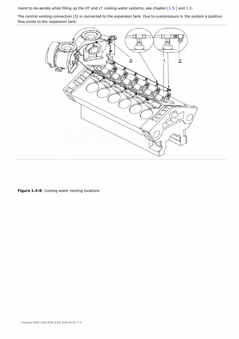
8/9/2019 W26 Instruction Manual
http://slidepdf.com/reader/full/w26-instruction-manual 68/304
P_0000045
mend to de-aerate while filling up the HT and LT cooling water systems, see chapter [1.5 ] and 1.2.
The central venting connection (3) is connected to the expansion tank. Due to overpressure in the system a positive
flow exists to the expansion tank.
Figure 1.4-8: Cooling water venting locations
Printed by DSME 의장설계2팀 송승화 2009-06-02 17:31

8/9/2019 W26 Instruction Manual
http://slidepdf.com/reader/full/w26-instruction-manual 69/304
P_0000045
1.5.1.General
The term "charge air" or "supercharging" refers to the practice of filling the cylinder, with air at a pressure
substantially higher than atmospheric pressure to support the combustion of the fuel, plus a sufficient excess to
control internal combustion and exhaust gas temperatures.
Supercharging is realised by a turbo charging system consisting of centrifugal compressor(s) each driven by an
exhaust gas turbine.
Turbochargers utilise energy in the exhaust gasses and improve the engine efficiency. The speed of turbochargers has
no fixed ratio to the engine speed but will vary with the load.
1.5.2.Quality of suction air filtration
The highest allowable concentration of dust and harmful components at the turbocharger inlet, after filtration, is given
in the table below.
Note! m³n is given at 0°C and 1013 mbar.
Measurements are to be performed during a 24-hour period and the highest 1-hour average is to be compared with
the above mentioned boundary values.
Weather conditions such as wind speed, wind direction, ambient temperature and air humidity may vary considerable
during one year. Therefore a one-day measurement may not reflect the most critical situation.
A detailed investigation concerning filtration has to be done in installations where the air includes components that are
known to be caustic, corrosive or toxic.
1.5.3.Internal system
Components of the internal system built-on the engine are:
Air intake filter with silencer on the turbocharger.
Turbocharger
Two stage charge air cooler with HT and LT section
Compressor cleaning device
The "Internal Charge Air Exhaust Gas System" diagram is provided in Annex A - Internal systems/Pipe arrangement,
of this Instruction Manual.
1.5.4.Charge air system
1.5.4.1.General
If the engine takes combustion air from the engine room, all combustion air should than first be supplied into the
engine room. The design of engine room ventilation, special in the vicinity of the charge air intake filters, can highly
influence the good performance of the engine combustion process. Full air supply to the air intake filter under arctic
conditions may create too low combustion gas temperature, and ambient air further heated in the engine room under
tropical conditions will raise the exhaust gas temperatures in the engine far too much. For good engine operation the
following should be taken into consideration:
1.5.Charge Air and Exhaust Gas System 1.5-PAAE062665-00
Property Unit
Dust concentration (particles > 5 µm) 3.0 [mg/m³n]
Chlorides (Cl) 1.5 [mg/m³n]
Hydrogen Sulphide (H2 S) 375 [µg/m³n]
Sulphur dioxide (SO2 ) 1.25 [mg/m³n]
Ammonia (NH3 ) 94 [µg/m³n]
Printed by DSME 의장설계2팀 송승화 2009-06-02 17:31

8/9/2019 W26 Instruction Manual
http://slidepdf.com/reader/full/w26-instruction-manual 70/304
P_0000045
Engine room ventilation should be such that water, foam, sand, dust exhaust smoke etc. can't enter the engineroom.
Avoid heating of fresh combustion air by striking hot engine room machinery.
In case the engine room temperature raises over 45°C the engine room ventilation ducting should be directed even
nearer to the turbocharger inlet filter to avoid further heating of the fresh air. If such situation cannot be arranged,derating of the engine load should be considered to avoid thermal overloading the engine.
Avoid discharge of generator cooling air to the turbocharger intake.
For restrictions on suction air temperatures, see chapter [2.3.]
It is recommended to have separate ventilators for combustion air and ventilating system provided. Air supply fans
must be dimensioned to obtain a slight over pressure in the engine room, but must not exceed 1 mbar.
Note!
For maintenance background information, safety aspects, intervals, tolerances, inspections, tools and torque spanner
instructions, see chapter [2.4.]
1.5.4.2.Charge air cooler
To maintain the required charged air temperature at higher engine load the charge air has to be cooled.
The temperature at the compressor discharge side at full load is approximately 200°C. To cool the charged air after
the compressor the air passes a two stage air cooler (1) in which the compressed air is cooled by water. See
[fig. 1.5-1] .
The first stage is cooled by HT water and cools the charge air till approximately 90-100°C. The second stage is cooled
with water from the LT water system and cools the charge air till the required temperature of approximately 50°C.
Figure 1.5-1: Charge air cooler
1.5.4.2.1.Cooler stack
The cooler stack (6), with build-on cooling water manifold (7) and cooling water box (8), is located inside a cast
housing (9).
At the bottom side the charge air in and outlet casings are provided with drain holes for condensate, which are
Printed by DSME 의장설계2팀 송승화 2009-06-02 17:31

8/9/2019 W26 Instruction Manual
http://slidepdf.com/reader/full/w26-instruction-manual 71/304

8/9/2019 W26 Instruction Manual
http://slidepdf.com/reader/full/w26-instruction-manual 72/304
P_0000045
Figure 1.5-3: Cooling water by-pass
1.5.4.3.Condensate draining
Check daily, during operation of the engine, if the condensate drain pipes located on the housing of the charge air
cooler and charge air receiver are open. Under normal operating conditions only compressed air should escape from
these holes and possible some condensate.
If excessive water escapes from the condensate drain pipes this can be caused by:
- Condensate due to high air humidity.
Condensate can be formed at the outside of the tubes of the LT part of the air cooler and is carried together with the
air into the combustion chambers of the cylinders.
The quantity of condensate depends on the suction air temperature, humidity, charge air pressure and charge air
temperature. There will always be some condensate on the pipes of the LT section of the charge air cooler. By
increasing the temperature of the the LT cooling water before the charge air cooler the quantity of condensate is
reduced.
Do not reduce the cooling water flow.
Excessive water (condensate) in the combustion chambers can cause corrosion on liners, piston rings and pistons andcold corrosion on fuel injector nozzles.
- Charge air cooler stack has one or more leaking tubes.
This should be confirmed by a lowering of the level of the HT and / or LT expansion tank. Check the kind of water
(treated water or not) Continuously water leaking when the engine is out of operation may indicate a leaking cooler
stack.
Inspection of the cooler stack on short notice is required.
Note!
Condensate drain points have the function to inform the operator on the presence of water in the charge air receiver.Condensate drain points are not designed to drain large quantities of water and should always be open.
Figure 1.5-4: Condensate drain points
1.5.4.4.Maintenance
Clean the cooler at intervals according to chapter [2.4.] or, if at full load, the charge air temperature cannot be
maintained.
Removal of charge air cooler stack
Drain the HT and LT cooling water from the engine and collect water for re-use.
Printed by DSME 의장설계2팀 송승화 2009-06-02 17:31

8/9/2019 W26 Instruction Manual
http://slidepdf.com/reader/full/w26-instruction-manual 73/304
P_0000045
Figure 1.5-5: Charge air cooler
1
2 Remove HT cooling water drain plug (11) and LT cooling water drain plug (12) from the cooler and collect
water for re-use, see [fig. 1.5-5] .
3 Disconnect and remove HT cooling water connecting pipes (2+3) from the cooling water manifold (7).
4 Disconnect LT cooling water connecting pipes (4+5) from the cooling water manifold (7).
5 Remove the heat protective panel (15).
6 After removal of panel (15) remove from the air cooler housing the front cover (16).
Printed by DSME 의장설계2팀 송승화 2009-06-02 17:31

8/9/2019 W26 Instruction Manual
http://slidepdf.com/reader/full/w26-instruction-manual 74/304
P_0000045
Figure 1.5-6: Removal charge air cooler stack
Mounting cooler stack
7 Mount transport slide (17) of tool [9612ZT949] on top of the charge air cooler housing with one bolt near the
cylinder block and with two pins (18) near the front side of the aircooler, see [fig. 1.5-6] .
8 Remove security plate (19) and place carrier (20). Replace security plate.
9 Slack all bolts (21) of side cover 3 turns.
10 Remove from the side cover two bolts (21) at top and fit two conducting pins (22) at the corners of the cooler
stack.
11 Insert pillar bolts (23) and push cooler stack in horizontal direction till it is free from the cylindrical support
(24) of the cooler stack housing.
12 Fit beam (25) with four cover bolts against the charge air cooler stack and with four M16x35 bolts to carrier
(20).
13 Pull the cooler stack out of the housing and support the charge air cooler stack if necessary.
14 Lift away the cooler stack with the aid of the two shackles (26 ).
15 Clean and check outer circumference of cooler housing.
16 Check if the cooler stack and housing are clean and free from scratches on metal sealings.
17 Fit carrier (20) together with beam (25) with four front cover bolts against the charge air cooler stack.
18 Mount transport slide (17) of tool [9612ZT949] on top of the charge air cooler housing with one bolt near the
cylinder block and with two pins (18) near the front side of the aircooler, see [fig. 1.5-6] .
19 Fit the two conducting pins (22) at side flange of cooler housing to guide the cooler stack.
20 Remove security plate (19) and lift carrier (20) together with beam and cooler stack onto the transport slide
(17). Replace security plate.
Printed by DSME 의장설계2팀 송승화 2009-06-02 17:31

8/9/2019 W26 Instruction Manual
http://slidepdf.com/reader/full/w26-instruction-manual 75/304
P_0000045
1.5.4.4.1.Cleaning
General
Cleaning of the water and air side of the charge air cooler is required to restore thermal cooler performance. Cleaning
can be done either mechanical, hydraulic or chemical. Several international companies supply equipment andchemicals for cleaning of heat exchangers.
Cleaning intervals vary with the mode of operation, cooling water and intake air quality, etc.
During cleaning the cooler should internally be inspected on scaling and corrosion.
Scale increases the risk of pitting corrosion and scale coming loose blocks the tubes leading to erosion.
Always check for erosion after cleaning.
Cleaning water side
Remove the water covers from the stack and inspect the tubes internally. When deposits are soft, which will occur in
most of the installations, use special nylon brushes connected to a rod. The type of brush must be selected in
accordance with the finned tube. Replace gaskets or O-rings.
Cleaning air side
Remove the cooler stack. To clean the fins of the tubes, immerse the stack in a chemical bath containing a degreasing
solvent. Raising and lowering the stack in the solution or bringing the solution into movement by means of a steam jet
or air, will accelerate the cleaning process. Direct after the cleaning is completed the cooler is to be flushed by
applying a powerful water jet
Note!
When using chemicals take the necessary precaution and follow the instructions provided by the manufacturer of the
chemicals.
Hydraulic cleaning
Hydraulic cleaning has to be carried out with the cooler stack removed using a high pressure spray gun with a special
nozzle to remove dirt deposits inside the tubes. For the outside of the tubes a nozzle with a diameter of 3 mm is
21 Roll the cooler stack into the charge air cooler housing.
22 Apply a liquid gasket material on flange of cooling water manifold. For gasket specs see parts catalogue.
23 Disconnect beam (25) from the charge air cooler stack.
24 Use jack bolts (27) to force the cooler stack side wards over the conducting pins (22). Pay attention that the
dowel pins fit into the corresponding side cover holes and the cylindrical support (24) of the cooler stack fits into
the recess of the housing.
25 Watch the correct mounting of the supporting ring (28).
26 Remove jack bolts and fit all side cover bolts.
27 Connect LT water connecting pipes and refit drain plug(s).
28 Connect HT water connecting pipes and refit drain plug(s).
29 Fill HT and LT water systems, pressurise systems and check cooler stack and water connections for leaks.
30 Remove carrier and transport slide from engine.
31 Replace front cover to charge air cooler housing.
32 Replace heat protective panel.
Printed by DSME 의장설계2팀 송승화 2009-06-02 17:31

8/9/2019 W26 Instruction Manual
http://slidepdf.com/reader/full/w26-instruction-manual 76/304
P_0000045
recommend. Attack the cooling tubes with the water yet vertical this means parallel to the fins. A suitable distance to
avoid damage is 2 meter.
Note!
When using a high pressure water cleaning device take care not to damage the fins. Damaged fins will result in an
decreased capacity of the cooler stack.
1.5.4.4.2.Repairs
Leaking tubes
Tube leaks can be caused by corrosion, erosion or improper operation of the cooler. A leaking tube cannot be
removed, they are roller expanded into tube plates.
Leaking tubes may be sealed by turned hardwood plugs or rubber plugs on both sides. Up till 10 tubes per system
may be sealed. Fit a new cooler stack or send the cooler stack for repair if more than 10 tubes are leaking.
Hydro test cooler with the specified test pressure which is stated on the name plate fitted on the cooler side wall or
casing.
Leaking seal
All seals are either O-rings, soft metal rings, gaskets or liquid gasket. If necessary disassemble the cooler as far asneeded. Remove dirt and corrosion residues and restore the surfaces in good shape again. Mount new seals.
1.5.5.Exhaust gas system
1.5.5.1.Exhaust gas manifold
The exhaust gas manifold is assembled of manifold sections (2) interconnected by compensators (3). Branches of the
manifold sections are rigid mounted via the multiduct (1) to the cylinder heads and cylinder block, see [fig. 1.5-7] .
The manifold is connected to the turbocharger.
The exhaust gas manifold requires under normal operation conditions no maintenance. A periodical inspection to
connections and to the condition of the compensators is sufficient.
The manifold can be inspected after removal of one or more panels from the insulation box.
Figure 1.5-7: Exhaust gas manifold configuration
Printed by DSME 의장설계2팀 송승화 2009-06-02 17:31

8/9/2019 W26 Instruction Manual
http://slidepdf.com/reader/full/w26-instruction-manual 77/304
P_0000045
1.5.5.2.Multiduct
The multiduct is a casting to conduct HT water, charge air (5) and exhaust gases (1), see [fig. 1.5-8] . The exhaust
channel (1), as part of the multiduct, is cooled by the HT cooling water, entering at (2) and leaving at (3). On top of
the multiduct is a vent connection (4) for the HT cooling water. After the cylinder head is removed, the multiduct
remains in place supporting the exhaust gas manifold.
Figure 1.5-8: Multiduct
Multiduct connection
Each multiduct (1) is connected to the engine block by 6 bolts (2) with distance bushes (3) and sealed with a gasket
(4) and (9), see [fig. 1.5-9] .
Figure 1.5-9: Sealing multiduct / cylinder head / cylinder block
The connection of the multiduct and exhaust gas manifold (5) is face to face; there is no gasket.
The sealing between multiduct and cylinder head for exhaust gas, charge air and HT water is by means of gasket (6).
Printed by DSME 의장설계2팀 송승화 2009-06-02 17:31

8/9/2019 W26 Instruction Manual
http://slidepdf.com/reader/full/w26-instruction-manual 78/304
P_0000045
This gasket is kept in the correct position during assembling with the aid of clips (7). The gasket needs to be replaced
every time the cylinder head is disconnected.
Tighten the bolts (8) according to the torque setting mentioned in section [2.4.4.] Tightening the multiduct bolts
requires the application of a torque spanner [9622ZT215] with extension [9612ZT332] .
1.5.5.3.Compensators
Compensators in the exhaust gas manifold enable thermal expansion of the manifold. Make sure that, whenever the
compensators have to be replaced, the arrow on the compensators corresponds to the gas flow direction. See
[fig. 1.5-10] . There is no gasket between compensators and exhaust manifold, it is a face to face connection.
Figure 1.5-10: Gas flow through compensators
Note!
When reinstalling a compensator check if flanges of the exhaust manifolds are in line and parallel. Maximum deviation
1mm.
1.5.5.3.1.'V' Clamp installation instructions
1.5.5.4.Insulation box
The insulation box (1), enclosing the exhaust gas manifold, is rigid mounted to the multiducts (2), see [fig. 1.5-11] .
1 Ensure flanges and sealing surfaces are clean.
2 Place compensator in position and ensure that the flanges assemble freely.
3 Fit the clamp 'V' sections (1) over the flange profiles. See [fig. 1.5-10] .
4 Engage the T-bolts through the trunnions and locate the nuts on the T-bolts.
5 Over-tighten the nuts evenly to 20 Nm, keeping the gaps equal on each side of the clamp, then slacken
them off half a turn.
Next tighten them to the recommended 9-12 Nm.
Printed by DSME 의장설계2팀 송승화 2009-06-02 17:31

8/9/2019 W26 Instruction Manual
http://slidepdf.com/reader/full/w26-instruction-manual 79/304
P_0000045
Figure 1.5-11: Insulation box
Warning!
The heat insulating box is not designed to carry weight.
The heat insulating material, as part of the panels, is at the inside cladded with stainless steel sheeting. This sheeting
should not be painted as part of the heat insulation exist in the reflection of heat radiation.
1.5.5.5.Maintenance
Well designed and installed exhaust gas systems require little maintenance and can be limited to long term visual
periodical inspections consisting of:
Inspection of all the connections in the exhaust gas manifold.
Inspection of all rigid and flexible mountings between exhaust gas system and the engine room structure. Specialattention should be paid to the support of the ducting after the turbocharger. (Load on the turbocharger is notallowed).
Inspection of the exhaust ducting insulation and cladding between turbocharger and uptake.
1.5.5.6.Operations
1.5.6.Turbocharger
The turbocharger consists of a single stage axial-flow turbine and a centrifugal air compressor connected by a single
rotor shaft supported on inboard bearings.
The inboard bearings are lubricated and cooled by the engine lubricating oil system.
The turbocharger is equipped with a cleaning device for the compressor side.
1 Check the working of water separating pockets and drainage system of the external exhaust system.
2 The exhaust gas back pressure should not exceed the maximum mentioned, see section
3 Check the good working of the sliding supports of the ducting after the turbocharger.
4 Check during operation of the engine the entire exhaust gas system on gas leakage's.
Printed by DSME 의장설계2팀 송승화 2009-06-02 17:31

8/9/2019 W26 Instruction Manual
http://slidepdf.com/reader/full/w26-instruction-manual 80/304
P_0000045
The rotor shaft rpm. is measured by a speed transmitter system installed at the compressor side and described in the
sub-suppliers manual of the turbo charger.
1.5.6.1.Maintenance
Maintain the turbocharger according instructions of the turbocharger manufacturer. It is recommended to make use of
the service network of Wärtsilä Corporation.
Use high temperature resistant grease on exhaust bolt connections.
1.5.6.2.Turbocharger cleaning devices
The diesel engine efficiency is highly related to the efficiency of the turbocharger. The turbocharger efficiency is
directly influenced by the degree of fouling of the compressor wheel, diffuser ring, nozzle ring and turbine wheel.
Regularly cleaning is essential during engine operation. The cleaning is not effective when the water cleaning is not
carried out on regularly schedule. See maintenance schedule section [2.4.1.]
The following factors may influence the degree of fouling e.g.:
Environment.
Fuel quality.
Load pattern.
Bad combustion.
1.5.6.3.Compressor side cleaning
The compressor should be cleaned by water injection during the engine operation. The cleaning process will have good
results as long as the deposit formation has not gone too far.
In this method of cleaning the water is not acting as a solvent but instead removes the deposits mechanically by the
impact of the water droplets. Use clean water without additives.
Daily cleaning of the compressor prevents or delays excessive build-up of dirt.In case a very thick hardened crust of
dirt is formed the compressor has to be dismantled for cleaning.
The cleaning system is provided with a water container (1). During cleaning the container is pressurised by the charge
air via line (2) by which water is forced to the compressor inlet via line (3).
Figure 1.5-12: Compressor cleaning device
Printed by DSME 의장설계2팀 송승화 2009-06-02 17:31

8/9/2019 W26 Instruction Manual
http://slidepdf.com/reader/full/w26-instruction-manual 81/304
P_0000045
Cleaning procedure
Water injection is to be executed when the engine is running at normal operating conditions and with a load >70% .
Record the charge air pressure, exhaust gas temperatures and the turbocharger speed to ascertain the efficiency of
cleaning.
1 Loosen grip screw (4) and remove container (1), see [fig. 1.5-12] .
2 Fill container with clean water.
3 Replace container and retighten grip screw (4).
4 By opening valve (5) charged air enters the container via pipe (2). The water content is via pipe (3) forced to
the compressor wheel inlet.
5 The complete water volume should be injected in 4 - 10 sec. The success of cleaning can be evaluated by
comparing engine exhaust gas temperatures before and after cleaning. If unsuccessfully, the cleaning process
should be repeated earliest after an interval of 10 minutes.
6 On completion of the cleaning process the engine should at least run another 5 minutes under load.
Printed by DSME 의장설계2팀 송승화 2009-06-02 17:31
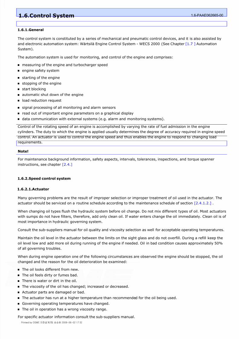
8/9/2019 W26 Instruction Manual
http://slidepdf.com/reader/full/w26-instruction-manual 82/304
P_0000045
1.6.1.General
The control system is constituted by a series of mechanical and pneumatic control devices, and it is also assisted by
and electronic automation system: Wärtsilä Engine Control System - WECS 2000 (See Chapter [1.7 ] Automation
System).
The automation system is used for monitoring, and control of the engine and comprises:
measuring of the engine and turbocharger speed
engine safety system
starting of the engine
stopping of the engine
start blocking
automatic shut down of the engine
load reduction request
signal processing of all monitoring and alarm sensors
read out of important engine parameters on a graphical display data communication with external systems (e.g. alarm and monitoring systems).
Control of the rotating speed of an engine is accomplished by varying the rate of fuel admission in the engine
cylinders. The duty to which the engine is applied usually determines the degree of accuracy required in engine speed
control. An actuator is used to control the engine speed and thus enables the engine to respond to changing load
requirements.
Note!
For maintenance background information, safety aspects, intervals, tolerances, inspections, and torque spanner
instructions, see chapter [2.4.]
1.6.2.Speed control system
1.6.2.1.Actuator
Many governing problems are the result of improper selection or improper treatment of oil used in the actuator. The
actuator should be serviced on a routine schedule according to the maintenance schedule of section [2.4.1.2.] .
When changing oil types flush the hydraulic system before oil change. Do not mix different types of oil. Most actuators
with sumps do not have filters, therefore, add only clean oil. If water enters change the oil immediately. Clean oil is of
most importance in hydraulic governing system.
Consult the sub-suppliers manual for oil quality and viscosity selection as well for acceptable operating temperatures.
Maintain the oil level in the actuator between the limits on the sight glass and do not overfill. During a refill keep the
oil level low and add more oil during running of the engine if needed. Oil in bad condition causes approximately 50%
of all governing troubles.
When during engine operation one of the following circumstances are observed the engine should be stopped, the oil
changed and the reason for the oil deterioration be examined:
The oil looks different from new.
The oil feels dirty or fumes bad.
There is water or dirt in the oil.
The viscosity of the oil has changed; increased or decreased. Actuator parts are damaged or bad.
The actuator has run at a higher temperature than recommended for the oil being used.
Governing operating temperatures have changed.
The oil in operation has a wrong viscosity range.
For specific actuator information consult the sub-suppliers manual.
1.6.Control System 1.6-PAAE062665-00
Printed by DSME 의장설계2팀 송승화 2009-06-02 17:32
8/9/2019 W26 Instruction Manual
http://slidepdf.com/reader/full/w26-instruction-manual 83/304
P_0000045
1.6.2.2.Booster
The booster activated by air the moment the engine is started, boosts the oil pressure in the actuator accumulator.
This makes fast response of the actuator power piston and fuel rack possible at initial start of the engine.
The booster supplies pressurized oil to mechanical-hydraulic actuators and electro-hydraulic actuators instantaneous
the starting air fills the starting air header on the engine. This instant oil pressure eliminates the time required for
gear pump in the actuator to build up enough oil pressure to move the linkage. This produces a faster start,
conserving starting air.
The booster is positioned lower than the actuator to prevent trapped air in booster and oil lines.
When the booster is inactive, the piston is held at one end of a cylinder by a spring. The cylinder is filled with oil
supplied from a line from the actuator's sump.
When the booster is activeted, engine starting air at the bottom side of the piston pressurises the oil which is forced
through ports and piping into the oil system of the actuator.
Check valves control the oil to flow in only one way.
This avoids the returning of booster oil during the starting process.
1.6.3.Fuel control mechanism
The movement of the power output shaft of the actuator is transferred to the common fuel control shaft (1) through a
link. The common fuel control shaft is supported to the engine block by bearings (2) and (3), see [fig. 1.6-1] .
Rotation of the common fuel control shaft is transferred through lever (4) to the HP fuel pump racks.
Torsion springs enable the common fuel control shaft to be moved to zero position in case one of the fuel racks will
jam.
Warning!
Special attention should be paid to the function of the fuel linkage mechanism as a defect to this mechanism may
result in a disastrous over speeding of the engine, unstable engine operation or an engine unable to take load.
Printed by DSME 의장설계2팀 송승화 2009-06-02 17:32

8/9/2019 W26 Instruction Manual
http://slidepdf.com/reader/full/w26-instruction-manual 84/304

8/9/2019 W26 Instruction Manual
http://slidepdf.com/reader/full/w26-instruction-manual 85/304
P_0000045
Figure 1.6-3: Linkage actuator / common control shaft
1.6.3.3.Checking linkage between fuel rack and common fuel control shaft
If necessary adjust the HP fuel pump racks to the average position. See section [1.6.3.3.]
2 Check if the angles between the levers (1) and (6) with rod (5) are about 90 °.
3 Check if the power output shaft (3) indicates ' 5 ' on the load
indicator (7) (scale 0-10).
4 If necessary adjust the length of rod (5) and secure all lockings on levers etc.
5 Place the HP fuel pump racks on position 0 mm by moving lever (6).
6 Check if the power output shaft (3) indicates between ' 0 and 0.5 ' on the load indicator scale (7).
7 Place the HP fuel pump racks on mid position (22 mm) by moving lever (6), see [fig. 1.6-3] .
8 Check if HP fuel pump rack position for A- and B-bank is equal.
9 Check if the angles between the levers (6) and (9) with rods (8) are about 90 °.
10 Check if the power output shaft (3) indicates ' 5.5 ' on the load indicator scale (7), ( scale 0-10 ) .
11 If necessary adjust the length of rod (5) and tighten the connections of the linkage to the specified torque,
see section [2.4.4.]
12 Place the HP fuel pump racks on position 0 mm by moving lever (6).
13 Check if the power output shaft (3) indicates between ' 0 and 0.5' on the load indicator scale (7).
1 Adjust spring loaded levers (7) with set screws (8) at a
Printed by DSME 의장설계2팀 송승화 2009-06-02 17:32

8/9/2019 W26 Instruction Manual
http://slidepdf.com/reader/full/w26-instruction-manual 86/304
P_0000045
Figure 1.6-4: Pre-clearance levers to HP fuel pump
Note!
The maximum deviation between fuel rack positions is ± 0.5 mm.
1.6.3.4.Stop mechanism
1.6.3.4.1.Manual stop
Move stop lever (6) from normal operating position 'A' into stop position 'B'. Check if pin (7) locks the stop lever see
[fig. 1.6-6] .
1.6.3.4.2.Local stop
Push stop button (2) on the engine mounted local control panel, see [fig. 2.3-1] . The stop signal activates solenoid
(7), see [fig. 1.6-5] , and air is admitted to the stop cylinders (5) mounted to the fuel racks of the HP fuel pumps. The
air pressure in the stop cylinders will be released after solenoid (7) is deactivated.
1.6.3.4.3.Remote stop
Push stop button in the control room. The stop signal deactivates the actuator controller, activates solenoid (7) (see
local stop) and if present the stop solenoid in the actuator.
1.6.3.4.4.Checking stop mechanism
Check of stop cylinder adjustment (limit position) and start blocking sensor (8). See [fig. 1.6-6] .
pre- clearence of 5 mm, see [fig. 1.6-4] .
2 Place actuator lever in mid position.
3 Record all HP fuel pump rack positions and calculate the average position. With set screws (8) all HP fuelpump rack readings should be adjusted at the average value calculated.
4 Check and if necessary adjust the linkage between the actuator and the common fuel control shaft. See
section [1.6.3.2.]
5 Secure all lockings on levers etc.
1 Place stop lever (6) in operating position 'A' see [fig. 1.6-6] .
2 Place actuator in maximum position (fuel pump racks in full position).
3 Push stop button (2) on the engine mounted local control panel, see [fig. 2.3-1] , to move all stop cylinder
pistons to zero position.
4 Check all fuel racks are moved into "zero" fuel position.
Printed by DSME 의장설계2팀 송승화 2009-06-02 17:32

8/9/2019 W26 Instruction Manual
http://slidepdf.com/reader/full/w26-instruction-manual 87/304
P_0000045
Figure 1.6-5: Stop device
1.6.3.5.Checking actuator stop position
Figure 1.6-6: Stop mechanism
1.6.3.6.Removing the actuator
5 Check the distance 'X' between the sensor tip and stop lever.
'X' must be between 1 and 1.5 mm. See [fig. 1.6-6] .
1 Place lever (6) in stop position 'B' see [fig. 1.6-6] .
2 Check if the power output shaft (3) indicates between ' 0 and 0.5 ' on the load indicator (7) (scale 0-10), see[fig. 1.6-3] .
3 Place lever (6) in stop position 'B' see [fig. 1.6-6] .
4 Check if the power output shaft (3) indicates between ' 0 and 0.5 ' on the load indicator (7) (scale 0-10), see
[fig. 1.6-3] .
5 Check all HP fuel pump racks are now in the 'no fuel position'. Position zero mm.
6 Release stop lever by pulling locking pin (7).
1Make a clear match mark on lever (1) and power shaft (3) for refitting the power shaft lever (1), see
[fig. 1.6-3] .
2 Remove lever (1) and disconnect electrical connections of actuator.
3 Drain actuator oil by opening the drain plug
Printed by DSME 의장설계2팀 송승화 2009-06-02 17:32

8/9/2019 W26 Instruction Manual
http://slidepdf.com/reader/full/w26-instruction-manual 88/304
P_0000045
Note!
The actuator should not rest on its drive shaft.
1.6.3.7.Mounting of the actuator
1.6.4.Governing system maintenance and trouble shooting
Maintenance of the actuator is limited and should mainly exist of:
periodically renewal and level control of the lubrication oil
observation to proper working of the actuator
observation to proper connections of the linkage mechanism
Trouble shooting
Fluctuations in engine speed or load are usual ascribed to an improper working of the actuator however before
exchanging or doing any inspection of the actuator check the following:
Fuel control mechanism maintenance
4 Remove pipe connections to booster.
5 Remove bolts (2) and lift actuator from engine.
1 Clean the joint faces of the actuator drive and engine block.
Check the condition of the serrated power shaft (3) of the actuator. See [fig. 1.6-3] .
2 During assembling use Loctite 5910 or similar as gasket.
3 Be careful not to damage the serrated drive sleeve when lifting the actuator into position.
4 Fasten bolts (2), booster pipe connections and electrical connections. See [fig. 1.6-3] .
5 Mount power shaft lever (1) according to the match mark on the power shaft (3).
6 Check the position of the actuator in relation with the HP fuel pump rack position, see section
1 Check engine load is not beyond maximum load.
2 Check if the fuel supply to the fuel pumps is at operating pressure and no vapour locks exist.
3 Check cylinder firing pressures and proper working of injectors.
4 Check adjustment of external setting devices of the actuator.
5 Check adjustment and linkage between actuator and fuel pumps.
6 The fuel control mechanism should be operated with minimal friction.
Bearings in linkages and on the common fuel control shaft require no lubrication and should not be in contact
with degreasing agents.
Pivoting point should be lubricated periodically with engine oil.
7 Keep all parts of the fuel control system clean and well preserved against rust.
8 Clearances of all connections should be minimal. Total backlash should not exceed 0.5 mm at the HP fuel
pump rack position.
Printed by DSME 의장설계2팀 송승화 2009-06-02 17:32
8/9/2019 W26 Instruction Manual
http://slidepdf.com/reader/full/w26-instruction-manual 89/304
P_0000045
Stop device maintenance
9 Check regularly the adjustment of the mechanism and actuators stop position.
10 Check and inspect filter/water separator.
11 Check control air pressure.
12 Check for air leaks.
13 Check stop cylinder parts for wear (piston, cylinder and sealing rings) and replace if necessary.
Printed by DSME 의장설계2팀 송승화 2009-06-02 17:32

8/9/2019 W26 Instruction Manual
http://slidepdf.com/reader/full/w26-instruction-manual 90/304
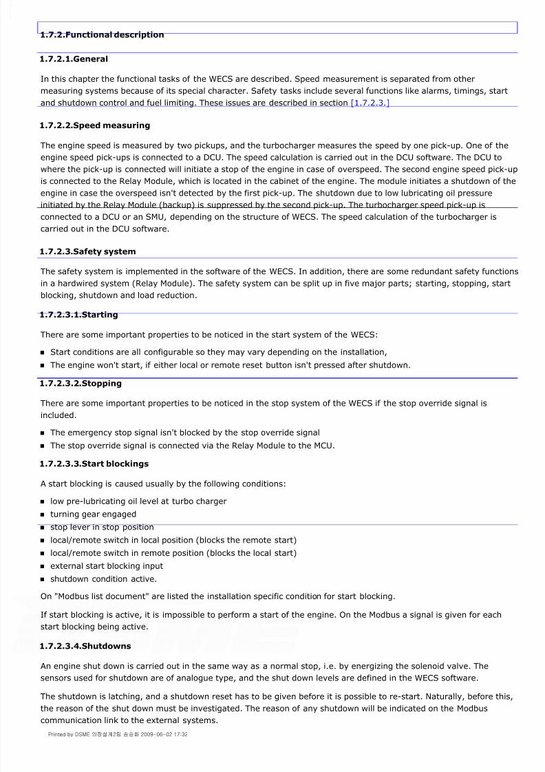
8/9/2019 W26 Instruction Manual
http://slidepdf.com/reader/full/w26-instruction-manual 91/304
P_0000045
1.7.2.Functional description
1.7.2.1.General
In this chapter the functional tasks of the WECS are described. Speed measurement is separated from other
measuring systems because of its special character. Safety tasks include several functions like alarms, timings, start
and shutdown control and fuel limiting. These issues are described in section [1.7.2.3.]
1.7.2.2.Speed measuring
The engine speed is measured by two pickups, and the turbocharger measures the speed by one pick-up. One of the
engine speed pick-ups is connected to a DCU. The speed calculation is carried out in the DCU software. The DCU to
where the pick-up is connected will initiate a stop of the engine in case of overspeed. The second engine speed pick-up
is connected to the Relay Module, which is located in the cabinet of the engine. The module initiates a shutdown of the
engine in case the overspeed isn't detected by the first pick-up. The shutdown due to low lubricating oil pressure
initiated by the Relay Module (backup) is suppressed by the second pick-up. The turbocharger speed pick-up is
connected to a DCU or an SMU, depending on the structure of WECS. The speed calculation of the turbocharger is
carried out in the DCU software.
1.7.2.3.Safety system
The safety system is implemented in the software of the WECS. In addition, there are some redundant safety functions
in a hardwired system (Relay Module). The safety system can be split up in five major parts; starting, stopping, start
blocking, shutdown and load reduction.
1.7.2.3.1.Starting
There are some important properties to be noticed in the start system of the WECS:
Start conditions are all configurable so they may vary depending on the installation,
The engine won't start, if either local or remote reset button isn't pressed after shutdown.
1.7.2.3.2.Stopping
There are some important properties to be noticed in the stop system of the WECS if the stop override signal is
included.
The emergency stop signal isn't blocked by the stop override signal
The stop override signal is connected via the Relay Module to the MCU.
1.7.2.3.3.Start blockings
A start blocking is caused usually by the following conditions:
low pre-lubricating oil level at turbo charger
turning gear engaged
stop lever in stop position
local/remote switch in local position (blocks the remote start)
local/remote switch in remote position (blocks the local start)
external start blocking input
shutdown condition active.
On "Modbus list document" are listed the installation specific condition for start blocking.
If start blocking is active, it is impossible to perform a start of the engine. On the Modbus a signal is given for each
start blocking being active.
1.7.2.3.4.Shutdowns
An engine shut down is carried out in the same way as a normal stop, i.e. by energizing the solenoid valve. The
sensors used for shutdown are of analogue type, and the shut down levels are defined in the WECS software.
The shutdown is latching, and a shutdown reset has to be given before it is possible to re-start. Naturally, before this,
the reason of the shut down must be investigated. The reason of any shutdown will be indicated on the Modbus
communication link to the external systems.
Printed by DSME 의장설계2팀 송승화 2009-06-02 17:32
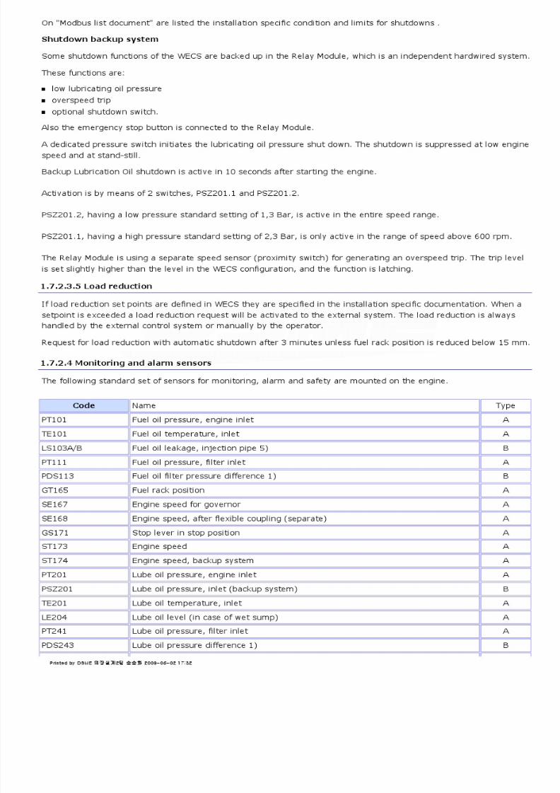
8/9/2019 W26 Instruction Manual
http://slidepdf.com/reader/full/w26-instruction-manual 92/304
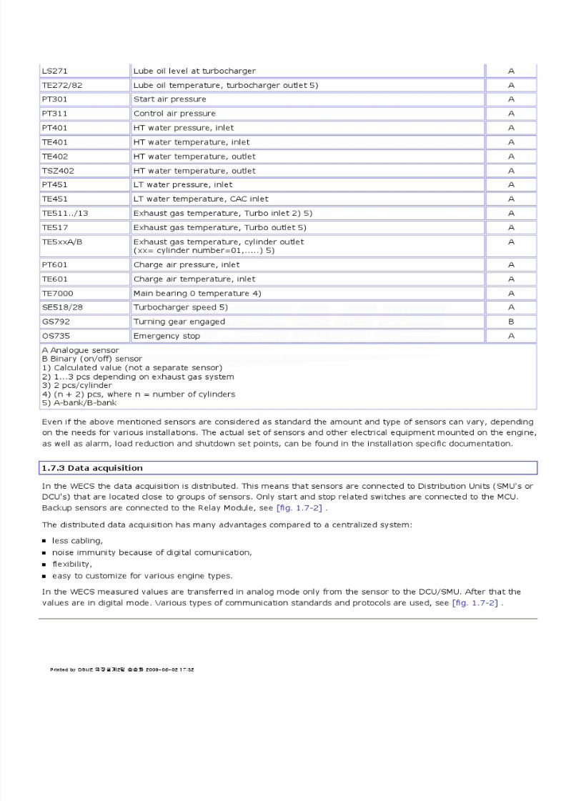
8/9/2019 W26 Instruction Manual
http://slidepdf.com/reader/full/w26-instruction-manual 93/304

8/9/2019 W26 Instruction Manual
http://slidepdf.com/reader/full/w26-instruction-manual 94/304
P_0000045
Figure 1.7-2: Sensor connection in the WECS
The data handling procedure in the WECS is shown in fig 1.7 - 3 . The sensor value is normally measured by the I/O
section of the SMU Board. Filtering, linearization and error check operations are made to the data and then it is
transferred to a DCU Board.
The DCU software verifies the validity of the measured data and checks the value against alarm, power reduction and
shutdown limits. After these operations the data is saved to the database of the DCU. Then the data is immediately
transferred via CAN to the MCU. The data receiving software in the MCU distributes the data to the Modbus and to the
database of the MCU. The data saved to the database of the DCU or the MCU can be used by several application
modules (like Math, LDU, etc.). These modules read values from the database and , in some cases, save producedvalues to the database. Data can also be transferred from the MCU database to the Modbus.
Figure 1.7-3: Data handling procedure
DCU/SMU
In the WECS sensors are normally connected to DCU/SMU's. The DCU includes the same sensor connections as the
SMU, but an additional PCB for CAN communication and data processing. Only two types of Distribution Units are
needed because their measuring channels are multiusage type. Various types of sensors can be connected to these
channels:
4-20 mA current loop,
current transducer,
voltage transducer,
Pt-100,
Printed by DSME 의장설계2팀 송승화 2009-06-02 17:32

8/9/2019 W26 Instruction Manual
http://slidepdf.com/reader/full/w26-instruction-manual 95/304
P_0000045
thermocouples of type J , K, S and T,
resistant,
potentiometer,
switch (max. 2 way).
Every measuring channel has an option to supply voltage for the sensor connected to it. Eight channels (0-7) supply
either 12 V DC or 15 V DC and two channels (8-9) supply 5 V DC.
There are also eight (8) digital inputs in the DCU/SMU's. Selectors are recommended to be connected to these inputs.
For the speed measuring there are two (2) frequency inputs in the DCU/SMU.
1.7.4.WEnCoM-functions
1.7.4.1.Background
The original WEnCoM was developed by Wärtsilä Diesel in the early 80's and comprised a microprocessor based
temperature measuring system designed for condition monitoring of diesel engines. The temperatures of the cylinder
liners, the main bearings and the exhaust gas valves were measured with thermocouples, presented on a CRT-screen
or printer as tables or charts and stored in a separate memory cassette. The system also performed certain
mathematical operations of the data. When the alarm levels were reached, the system generated alarms or shutdown
signals for the engine.
Today WEnCoM is divided into two parts: the safety functions included in the WECS and the trend diagrams
implemented in the external system. The external system in this meaning is any control, alarm or monitoring system
connected to the WECS. The temperature measuring of the cylinder liners, main bearings and the exhaust gas valves,
the checking against alarm, power reduction and shutdown levels and the needed mathematical operations are all
included in the WECS.
The presentations of all measured and calculated data should be implemented, according to the recommendations, in
the external system connected to the MCU. Depending on engine type and size the amount of sensors included for the
WEnCoM-functions may vary.
1.7.4.2.Main bearings
The temperature of the main bearing is monitored with the sensor in direct contact with the bearing shell, see
[fig. 1.7-4] . Alarm, power reduction or shutdown is generated if the value exceeds specified limits. The updating
frequency is 1 Hz.
Figure 1.7-4: Temperature sensors of the main bearing
Note!
It is recommended to have trend diagrams of the main bearing temperatures in the external system.
1.7.4.3.Exhaust gas valves
Printed by DSME 의장설계2팀 송승화 2009-06-02 17:32
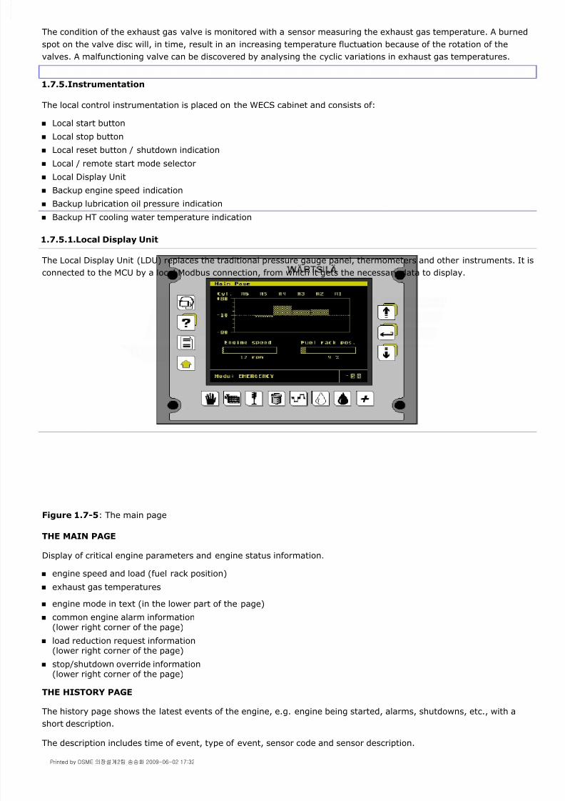
8/9/2019 W26 Instruction Manual
http://slidepdf.com/reader/full/w26-instruction-manual 96/304
P_0000045
The condition of the exhaust gas valve is monitored with a sensor measuring the exhaust gas temperature. A burned
spot on the valve disc will, in time, result in an increasing temperature fluctuation because of the rotation of the
valves. A malfunctioning valve can be discovered by analysing the cyclic variations in exhaust gas temperatures.
1.7.5.Instrumentation
The local control instrumentation is placed on the WECS cabinet and consists of:
Local start button
Local stop button
Local reset button / shutdown indication
Local / remote start mode selector
Local Display Unit
Backup engine speed indication
Backup lubrication oil pressure indication
Backup HT cooling water temperature indication
1.7.5.1.Local Display Unit
The Local Display Unit (LDU) replaces the traditional pressure gauge panel, thermometers and other instruments. It is
connected to the MCU by a local Modbus connection, from which it gets the necessary data to display.
Figure 1.7-5: The main page
THE MAIN PAGE
Display of critical engine parameters and engine status information.
engine speed and load (fuel rack position)
exhaust gas temperatures
engine mode in text (in the lower part of the page)
common engine alarm information(lower right corner of the page)
load reduction request information(lower right corner of the page)
stop/shutdown override information(lower right corner of the page)
THE HISTORY PAGE
The history page shows the latest events of the engine, e.g. engine being started, alarms, shutdowns, etc., with a
short description.
The description includes time of event, type of event, sensor code and sensor description.
Printed by DSME 의장설계2팀 송승화 2009-06-02 17:32

8/9/2019 W26 Instruction Manual
http://slidepdf.com/reader/full/w26-instruction-manual 97/304
P_0000045
A = Alarm
B = Startblock
S = Shutdown
E = Emergency
L = Load reduction
M = Mode change
N = Note (e.g. for indication that a pump starts)
THE SYSTEM PAGE
There are always several system pages. The number of pages varies depending on the number of sensors in the
WECS. One system page shows values of logical sensor groups like for example main bearing temperatures.
Start blocks and air pressures
Engine performance
Exhaust gas
Crankcase
Water systems
Oil systems
Logical name
Analog value (abnormal value inverted)
Bar graph
THE KEY BUTTONS
The MAIN key takes you to the main page. Use the HISTORY key to view alarm and shutdown history.
The F8 key takes you to a menu of additional pages. To choose a page use the UP and DOWN keys and select with the
ENTER key.
Use the HELP key to show the help page.
Figure 1.7-6: The key buttons on the panel
The keys F1-F7 take you to the status page of a logical group of sensors according to description below:
F1: Start blockings & air pressures
F2: Engine performance
F3: Exhaust gas temperatures
F4: Cylinder liner temperatures (not applicable on W26 engine)
F5: Main bearing temperatures
F6: Cooling water systems
F7: Fuel and lubricating oil systems
Some system pages are divided into several pages. When a page is divided, an arrow is displayed in the upper right
Printed by DSME 의장설계2팀 송승화 2009-06-02 17:32

8/9/2019 W26 Instruction Manual
http://slidepdf.com/reader/full/w26-instruction-manual 98/304
P_0000045
corner. Use the UP and DOWN keys to scroll pages within the same level.
All main levels have two sub levels: a STATUS level and a SERVICE level. The levels are indicated by a hollow arrow.
Use SHIFT+UP or SHIFT+DOWN to change level
MODBUS ACTIVE INDICATION
In the upper right corner there is an indication of the MODBUS status. If the MODBUS is up and running the indicator
will flash continuously. If the MODBUS is not working properly, the indicator is black.
1.7.5.2.Backup instruments
In addition to the LDU there are three backup instruments that are independent from the rest of the system. The three
instruments are: engine speed, HT cooling water temperature and lubricating oil pressure.
1.7.5.3.Controls
The control functions local/remote, start, stop and shutdown reset are included in the control panel. The functions and
layout of the control panel may vary depending on engine type.
Local/Remote
There are two modes, local and remote. In local mode the start can be executed only locally from the control panel not
from the control room. The remote mode differs between marine and power plant applications.
Start
The start button is used to start the engine locally.
Stop
The stop button is used to stop the engine locally.
Shutdown reset
After an automatic shutdown the control system is to be resetted before the engine can be started again. This is due
to safety requirements. A blue light in the reset button indicates an automatic shutdown. After reset the light turns off.
1.7.6.Functional testing
In this section there are described the procedures for testing of overspeed trip and pressure sensors.
1.7.6.1.Testing of overspeed trip
There are two sensors measuring the engine speed. One sensor (ST173) is connected to a DCU/SMU and the other
sensor (ST174) is connected to the Relay Module. Overspeed is detected by both sensors.
The overspeed limit set in the DCU/SMU is lower than the overspeed limit set in the Relay Module. The limit of
overspeed in the DCU/SMU is 15 % above the engine nominal speed. The limit of overspeed in the Relay Module is
18% above the engine nominal speed.
The overspeed trip can be tested by actually running the engine at overspeed if that is possible. Otherwise the testing
has to be done by simulating the engine speed with a signal generator.
The overspeed trip should stop the engine when the overspeed limit is exceeded.
The overspeed trip on the Relay Module is a backup of the normal overspeed trip.
Warning!
If the WECS does not receive both signals from the speed sensors ST173 and ST174 the safety and alarm system is
NOT fully activated. Running of the engine, however, is still possible but this could lead to serious engine damage.The absents of both signals can be seen during engine start-up. On the "Main page" of the WECS-screen, first the
signal "Start fail or rpm missing" and after a while "Start blocked" appears. An alarm "SS174 Engine speed" will be
activated when one ore both signals fail.
1.7.6.1.1.Testing of overspeed trip by running the engine
Printed by DSME 의장설계2팀 송승화 2009-06-02 17:32

8/9/2019 W26 Instruction Manual
http://slidepdf.com/reader/full/w26-instruction-manual 99/304
P_0000045
The overspeed trip can be tested by running the engine at overspeed. The speed of the engine is not allowed to be
increased more than 60 rpm over the over speedlimit.
The limit of overspeed will be first exceeded in the DCU/SMU.
When testing the overspeed trip of the Relay Module the speed sensor of the DCU/SMU (ST173) has to be
disconnected.
Note!
Do not forget to connect the speed sensor after testing!
1.7.6.1.2.Testing of overspeed trip by using a signal generator
The speed is detected from the camshaft gear. The rotation speed of the camshaft gear is half of the engine rotation
speed. The frequency corresponding to the overspeed can be easily calculated when the teeth number of the camshaft
gear is known.
Note!
The Relay module is delivered with the "Record Relay Module Tuning document" where are indicated all the test
frequecies and the Relay Module's set points.
The following formula gives the frequency detected by the sensor corresponding to engine speed:
The frequency corresponding to the engine speed is shown in the following tables with engine nominal speed of 900
rpm and 1000 rpm accordingly and a camshaft gear with 46 teeth.
1 Increase the engine speed
2 Check at what speed the overspeed is detected
1 Connect the signal generator to both speed sensors one at a time. The signal generator is connected to the
pins signal and gnd of the speed sensor. See fig 1.7 - 24 for connections. The overspeed stop should be
detected when the overspeed limit is exceeded.
The signal for the test should be a wave with amplitude minimum 12 V.
2 Increase the frequency of the input signal.
3 Check at what frequency the overspeed is detected.
. Frequencycorresponding
to speed
900 rpm (nominal speed) 345 Hz
1035 rpm (15% overspeed limit, DCU/SMU) 396 Hz
1062 rpm (18% overspeed limit, RM) 407 Hz
. Frequencycorrespondingto speed
1000 rpm (nominal speed) 383 Hz
1050 rpm (15% overspeed limit, DCU/SMU) 440 Hz
1180 rpm (18% overspeed limit, RM) 452 Hz
Printed by DSME 의장설계2팀 송승화 2009-06-02 17:32

8/9/2019 W26 Instruction Manual
http://slidepdf.com/reader/full/w26-instruction-manual 100/304
P_0000045
1.7.6.1.3.Testing of pressure switches (back-up)
The testing of pressure sensors can be done with a pressure calibration device.
Figure 1.7-7: Testing of pressure switches
In figure 1.7 - 7 there is a pressure switch with a shut-off valve and a test pressure connection. The pressure switch is
disconnected from the pressure with the shut-off valve. The pressure calibration device is then connected to the plug
for test pressure. A requested pressure is set with the help of the calibration device.
Note!
Do not forget to open the shut-off valve after testing!
1.7.7.Hardware
1.7.7.1.General
This section covers the whole range of WECS hardware units, summarizing their technical and physical properties.
Enclosure and frame characteristics like dimensions are also described. Most PCB's are illustrated with a layout figure
and a block diagram including I/O description. DIP-switches, jumpers, trimmers and indicators are discussed whenever
they exist.
1.7.7.2.Main Control Unit
The MCU consist s of a series of boards that combine to provide all requirements for data acquisition, control, and
communication. The basic concept of the MCU includes the Frame, the Mother Board, the Processor Board, the DC/DC
Converter, the Memory Unit, the LAN Board and two Interface Boards.
Printed by DSME 의장설계2팀 송승화 2009-06-02 17:32

8/9/2019 W26 Instruction Manual
http://slidepdf.com/reader/full/w26-instruction-manual 101/304
P_0000045
Figure 1.7-8: MCU frame
1.7.7.2.1.Frame
The aluminum frame provides a compact housing for the interconnection of the MCU boards and cable ground
terminals. The MCU frame has provision optional Interface Boards.
1.7.7.2.2.Motherboard
The DMB50 Mother Board is mainly a busboard having no electrical functions of its own. It is divided into a group of
buses and the power connection circuitry. Refer to [fig. 1.7-9] when reading the following sections.
Figure 1.7-9: Layout of mother Board
1.7.7.2.3.DC/DC Converter
The DPS50 DC/DC Converter is a multifunction switcher power supply board for the MCU. It carries four independent
supplies and circuits for control and BIT purposes.
The functional blocks of the DC/DC Converter are shown in [fig. 1.7-11]
Printed by DSME 의장설계2팀 송승화 2009-06-02 17:32

8/9/2019 W26 Instruction Manual
http://slidepdf.com/reader/full/w26-instruction-manual 102/304

8/9/2019 W26 Instruction Manual
http://slidepdf.com/reader/full/w26-instruction-manual 103/304
P_0000045
Figure 1.7-12: Layout of the Processor Board
Figure 1.7-13: Block diagram of the Processor Board
1.7.7.2.5.Memory Unit
The DMM50 Memory Unit enables the use of removable PC Cards for program and configuration upgrading.
Figure 1.7-14: Memory Unit Layout
LED indicators
The PC Card drives A and B both have an LED for indicating their activity. The indicator is green or red depending on
the type of activity. The STATUS-LED is also located on the front panel of the Memory Unit.
1.7.7.2.6.LAN Board
Printed by DSME 의장설계2팀 송승화 2009-06-02 17:32

8/9/2019 W26 Instruction Manual
http://slidepdf.com/reader/full/w26-instruction-manual 104/304

8/9/2019 W26 Instruction Manual
http://slidepdf.com/reader/full/w26-instruction-manual 105/304
P_0000045
Figure 1.7-17: Layout of the Interface Board
Figure 1.7-18: Block Diagram of the Interface Board
1.7.7.3.Distribution Unit
The Distribution Unit can either be a Sensor Multiplexer Unit (SMU) including an SMU Board or a Distributed Control
Unit (DCU) including both an SMU Board and a Control Board.
Figure 1.7-19: SMU and DCU
Printed by DSME 의장설계2팀 송승화 2009-06-02 17:32

8/9/2019 W26 Instruction Manual
http://slidepdf.com/reader/full/w26-instruction-manual 106/304
P_0000045
The SMU is a microprocessor based measuring unit, designed for continuous operation in harsh environmental
conditions. It acts as an interface between sensors and a DCU. The SMU can measure both analog and digital sensors.
It stores data of one measurement at a time to its SRAM memory. The data is transmitted from the memory to the
host processor by a separate command. The SMU also performs linearization of temperature sensors and error
checkups. The SMU is connected to the host processor through one serial line channel. This channel is a galvanically
isolated RS-485 half-duplex connection and each SMU has its own address to which it responds.
A DCU comprises an SMU Board and a DCU Board on the lid of the enclosure. These boards are connected to each
other with a flat cable. In addition to the features of the SMU the DCU Board adds a more power full microprocessor,
flash memories, a PC Card socket and a CAN controller.
1.7.7.3.1.SMU board
The SMU Board is rather flexible in application in a variety of possible configurations. Various types of sensors can be
connected to it:
4-20 mA current loop
current transducer
voltage transducer
Pt-100
thermocouples of type J, K, S and T
resistant
potentiometer
switch (max. 2 way)
Figure 1.7-20: SMU Board layout
The SMU Board includes an 8-bit Intel 80C51FC CPU running with clock frequency 14.7 MHz. The SMU Board also has
a memory circuit for storing operation variables and system parameters. The AD conversion is made with a 16-bit
sigma/delta A/D converter with digital filter and gains.
The SMU Board converts all the required operating voltages for itself from the 24 V level. The switching power supply
of SMU is isolated. The SMU Board floats from other electronics of the WECS because of isolated power supply.
Printed by DSME 의장설계2팀 송승화 2009-06-02 17:32

8/9/2019 W26 Instruction Manual
http://slidepdf.com/reader/full/w26-instruction-manual 107/304

8/9/2019 W26 Instruction Manual
http://slidepdf.com/reader/full/w26-instruction-manual 108/304
P_0000045
1.7.7.4.Sensors
1.7.7.4.1.Speed sensors
Engine speed sensor
The rotation speed of the engine is measured with two touch free inductive PNP-type proximity switches. The sensor is
supplied with a 10 - 30 V DC supply voltage (normally 15 V DC in the WECS). The third pin of the sensor is the speed
proportional pulse train output. The voltage level of pulse output varies between two fixed levels; 0 V DC and +15 V
DC (supply voltage).
The electronics of the sensor is resin-molded into a tubular housing of nickel-plated brass with external thread of M18
x 1.5 mm. The cable is connected by means of a four-pole Euchner BS4 connector.
To install the sensor turn the engine until the top of a cog is visual in the sensor mountinghole. Screw carefully the
sensor completely in by hand. Unscrew it approximately 1.5 revolutions for a sensing distance of 2.0 - 2.5 mm, and
tighten the counter nut well with a spanner.
Figure 1.7-24: Engine speed sensors
ABB TPS turbocharger speed sensor
The turbocharger speed sensor is a magnetic type and it does not require any supply voltage. The sensor is mounted
eccentrically in the turbocharger's bearing space cover. In a lubricating wheel on the shaft there are six embedded
magnets, which generate a pulse in the sensor when passing the sensing head. The sinusoidal signal from the sensor
is thus proportional to the rotation speed of the charger, and connected to the WECS.
The metal housing of the sensor is M12 x 1.25 mm. The cable is connected by means of a four-pole connector.
To install the sensor, screw carefully the sensor completely in by hand. Do not forget to install the gasket as well.
Tighten the sensor well with a spanner, with a tightening torque of 15 Nm.
Figure 1.7-25: ABB turbocharger speed sensor
FLASH Yellow Continuously ON when FLASH voltage is connected (normally duringconfiguration or software loading)
RESET Red Indicates system reset at start-up, during manual reset or in insufficientpower supply conditions
Printed by DSME 의장설계2팀 송승화 2009-06-02 17:32

8/9/2019 W26 Instruction Manual
http://slidepdf.com/reader/full/w26-instruction-manual 109/304
P_0000045
EGT turbocharger speed sensor
The speed sensor of the EGT turbocharger functions like the speed sensor of the ABB turbocharger except that it gives
either two, six , nine or thirteen pulses during each revolution of the TC shaft.
The metal housing of the sensor has 5/8" UNF thread. The length of the sensor depends on the exact type of
turbocharger as shown in table 3-4.
Figure 1.7-26: EGT turbocharger speed sensor
1.7.7.5.Solenoid valves
The solenoid valves used on the engines are 3-way type valves of make E. Seitz. They can, depending on the
application, either be normally open or normally closed. The nominal operation voltage is 24 V DC, and the solenoids
have a voltage tolerance of -15 % to +10 %. The coil has a power rating of 11 W and it has (built-in) voltage
suppression and reverse polarity protection diodes.
1.7.7.6.Relay Module
The Relay Module is a device that executes orders from the MCU by means of activating solenoids etc. It also serves
as a safety backup system when the main safety system doesn't work properly or if the rest of the system is out of
operation. Most of the hardwired signals as the emergency switch etc. are connected to the Relay Module. The Relay
Module also provides power supply for the whole system.
Unlike the other units of the WECS the Relay Module has no processor or software. Consequently the Relay Module is a
totally hardware driven unit. The Relay Module consists of the following functional blocks:
speed measuring block (backup)
lube oil shut down block (backup)
optional shutdown block (backup)
MCU stop/shutdown block
hardwired stop block overspeed shutdown block (backup)
emergency stop block
MCU watch dog block
stop/shut down override block
shutdown reset block
EGT turbocharger speed sensor
Turbocharger type Pulses
Napier 155 2
Napier 295 2
Napier 297 G-wheel 9
Napier 297 GS-whell 13
Napier 355 2
Napier 457 6
Napier 557 6
Printed by DSME 의장설계2팀 송승화 2009-06-02 17:32
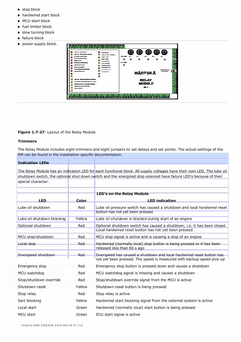
8/9/2019 W26 Instruction Manual
http://slidepdf.com/reader/full/w26-instruction-manual 110/304
P_0000045
stop block
hardwired start block
MCU start block
fuel limiter block
slow turning block
failure block
power supply block.
Figure 1.7-27: Layout of the Relay Module
Trimmers
The Relay Module includes eight trimmers and eight jumpers to set delays and set points. The actual settings of the
RM can be found in the installation specific documentation.
Indication LEDs
The Relay Module has an indication LED for each functional block. All supply voltages have their own LED. The lube oil
shutdown switch, the optional shut down switch and the energized stop solenoid have failure LED's because of their
special character.
LED's on the Relay Module
LED Color LED indication
Lube oil shutdown Red Lube oil pressure switch has caused a shutdown and local hardwired resetbutton has not yet been pressed
Lube oil shutdown blocking Yellow Lube oil shutdown is blocked during start of an engine
Optional shutdown Red Optional shutdown switch has caused a shutdown; i.e. it has been closed.Local hardwired reset button has not yet been pressed
MCU stop/shutdown Red MCU stop signal is active and is causing a stop of an engine
Local stop Red Hardwired (normally local) stop button is being pressed or it has beenreleased less than 60 s ago
Overspeed shutdown Red Overspeed has caused a shutdown and local hardwired reset button hasnot yet been pressed. The speed is measured with backup speed pick-up
Emergency stop Red Emergency stop button is pressed down and causes a shutdown
MCU watchdog Red MCU watchdog signal is missing and causes a shutdown
Stop/shutdown override Red Stop/shutdown override signal from the MCU is active
Shutdown reset Yellow Shutdown reset button is being pressed
Stop relay Red Stop relay is active
Sart blocking Yellow Hardwired start blocking signal from the external system is active
Local start Green Hardwired (normally local) start button is being pressed
MCU start Green ECU start signal is active
Printed by DSME 의장설계2팀 송승화 2009-06-02 17:32

8/9/2019 W26 Instruction Manual
http://slidepdf.com/reader/full/w26-instruction-manual 111/304

8/9/2019 W26 Instruction Manual
http://slidepdf.com/reader/full/w26-instruction-manual 112/304
P_0000045
Figure 1.7-28: Software structure of the WECS
1.7.9.Maintenance of electrical contacts
To prolong the lifetime of electrical contact surfaces and to provide proper electrical connection under all conditions
and to maintain a high availability of the WECS system.
The maintenance is carried out by applying contact lubricats to electrical contact surfaces. for best result the contact
surface should be cleaned with aereosol electrical contact cleaner before applying the lubricant.
Contact lubricants are specially formulated greases and oils that reduce friction and enhance the electrical
performance of current carrying metal interfaces in switches and connectors. They also exhibit a neutral pH thereby
avoiding surface corrosion.
Note!
Prior to use read the product information.
Action 1 Preliminary actions
Step 1 Stop the engine.
Step 2 Switch off the WECS engine control and monitoring system.
Warning!
If Check there is no tension in CAN-bus
Action 2 Cleaning of the DCUs and SMUs
Step 3 Loosen the four screws in the cover by using an allen key and open the cover (01) (See [Fig. 1.7-29] ).
Step 4 Clean the box inside with a soft cloth.
Action 3 Lubricating of electrical contacts
Step 5 Loosen all the screws of the first Phoenix connector and remove the connector (02).
Step 6 Clean the connections and spread some electrolube grease (03).
Note!
If electrolube grease is missing use CRC for electric circuit.
Step 7 Press down the Phoenix connector by finger tips and tighten all the screws.
Step 8 Check all the cable connections.
Printed by DSME 의장설계2팀 송승화 2009-06-02 17:32

8/9/2019 W26 Instruction Manual
http://slidepdf.com/reader/full/w26-instruction-manual 113/304
P_0000045
Step 9 In case of DCU reset it by pushing the relevant button (04).
Figure 1.7-29: Lubricating of contacts
1.7.10.List of abbreviations
AC Alternative Current
A/DC Analog to Digital Conversion
AMX Real time operating kernel
BIT Built-In-Test
bit Binary digit 0 or 1 used in computers
bps bits per second
CA Charge Air
CAC Charge Air Cooler
CAN Controller Air Network
CIL Command Line Interpreter
CRC Cyclical Redundancy Check
CRT Cathode Ray Tube
CTS Clear To Send
D/AC Digital to Analog Conversion
DC Direct Current
DCU Distribuited Control Unit
DIP Dual In-line Package
Printed by DSME 의장설계2팀 송승화 2009-06-02 17:32

8/9/2019 W26 Instruction Manual
http://slidepdf.com/reader/full/w26-instruction-manual 114/304
P_0000045
DOS Disk Operating System
DPM Digital Panel Memory
DRAN Dynamic Random Acces Memory
DUART Dual Universal Asynchronous
Reciver/Transmiter
DTE Data Terminal Equipment
EEPROM Electrically Erasable Programmable Read Only Memory
ELD Electro luminescent dispay
EMC Electro Magnetic Interference
EPROM Erasable Programmable Read Only Memory
ESD Electro Statictic Discharge
FAT File Allocation Table usaed By DOS to
allocate files on a disk
FFT Fast Fourier Transformation
FLASH Electrically erasable EPROM memory
FSR Full SCale Range
GND Ground
HT High Temperature
HW Hardware
I2C Medium speed, multimaster, two wire bus of
Philips
ID Identification Number of a SMU
ID-EEPROM Serially controlled Identification
EEPROM on each MCU board
I/O Input/ Output
LAN Local Area Network
LDU Local Dispay Unit
LED Light Emitting Diode
LOC Lubricating Oil Cooler
LRU Lowest Replaceable Unit
LT Low Temperature
LSB Least Significant Bit
Mb Mega bit (one million bits)
MB Mega Byte (one million bytes)
MCU Main Control Unit
MODBUS Industrial, one master bus of Modicon
MSB Most Significant Bit
MSG Message
Printed by DSME 의장설계2팀 송승화 2009-06-02 17:32

8/9/2019 W26 Instruction Manual
http://slidepdf.com/reader/full/w26-instruction-manual 115/304

8/9/2019 W26 Instruction Manual
http://slidepdf.com/reader/full/w26-instruction-manual 116/304
P_0000045
TJ Thermocouple type J
TK Thermocouple type K
TS Thermocouple type S
TT Thermocouple type T
TXD Transmitted Data (RS232-C)
UNF Thread standard
VEP Vaisala Enhanced Protocol
VGA Video Grafphics Arry
VRX Real-time operating system
shell "Vaisala Real-time eXecutive"
WECS Wärtsilä Engine Control System
WEnCoM Wärtsilä ENgine COndition monitoring
XT Personal computer including
Intel 086/088 compatible processor
Printed by DSME 의장설계2팀 송승화 2009-06-02 17:32

8/9/2019 W26 Instruction Manual
http://slidepdf.com/reader/full/w26-instruction-manual 117/304
P_0000045
2.3.1.General
Before an operator takes an engine a first time in operation he should be acquainted with the location and function of
the components of the installation.
It is desirable, in case of new installations or those which have been out of service for some time, before starting, that
the operator tests all fuel, lubricating oil, water and air lines, to see they are tight and functional.
Air should be purged from liquid systems through vents at the highest point while filling or circulating the liquid.
The engine should be cranked a few revolutions to ensure there are no restrictions. After all necessary preparations
have been made prior to starting, the engine should run at idle speed recommended in the main data, see chapter
[1.0.] The engine speed should be increased gradually while observing pressures and temperatures to make sure all
parts are working properly.
Wärtsilä Corporation issues instructions for each engine and such instructions are the result of wide experience. To
secure the utmost in reliability and efficiency these instructions should be read, understood, and followed.
All well-managed installations maintain engine log sheets. The logs should have provision for recording the starting
and stopping time of each engine, the loads, pressures and temperatures. These logs are usually based on a 24-hours
operating period and provide space for each of the shift engineers. Well maintained logs will provide an invaluable
record of the performance of the engines and all maintenance made or needed.
2.3.1.1.Preheating
In a stand-by preheated mode the engine is ready to accept load instantly.
Stand-by preheated mode of the engine means:
Fuel must be of the correct viscosity in the internal engine system.
HT cooling water must be preheated as near as possible to the operating temperature or at least to a temperature
of minimum 60°
C by means of an external preheating system. Preheating water flow shall be minimum 4% ofnominal water flow.
Lubricating oil temperature minimum 40 °C.
2.3.1.2.Preparations before the start
Before a trial run and after maintenance/repairs or a prolonged stop, the engine and system should be thoroughly
inspected and prepared for operation.
Before an engine is started, pay attention to:
Levels in tanks.
Systems vented.
Check correct valve positions in supply and discharge on the engine.
Observe the system diagrams.
Required coolers are in service.
Leaking pipes.
Safety systems tested and operational.
Check crankcase for possible water leakages from liner walls.
Cooling water has preheated the engine.
Fuel is circulating at the required pressure and viscosity.
The prelubricating to the engine is correct.
Filters on differential pressures.
Starting air vessels are on pressure and drained from water and oil.
Gauges for normal readings.
All covers are closed and locked.
Prohibiting tags removed.
Start blocking is released.
Engine and engine shafting clear for rotating.
2.3.Operation 2.3-PAAE062665-00
Printed by DSME 의장설계2팀 송승화 2009-06-02 17:33

8/9/2019 W26 Instruction Manual
http://slidepdf.com/reader/full/w26-instruction-manual 118/304
P_0000045
Engine room is free of obstructions.
Bar engine two revolutions with indicator cocks open.
Note!
Keep engine clear during start-up and operation.
2.3.1.3.Local start
Warning!
In case a stand-by pump is used for prelubrication prevent continuous operating to avoid excessive fouling of the
turbocharger. See also sub-suppliers manual of the turbocharger.
Figure 2.3-1: Local control panel
pressures of the engine systems
1 Depending on the system, start the prelubricating oil system to obtain the start blocking release. If anexternal full flow lubricating oil pump is installed adjust the pressure at nominal. See section [1.0.4.]
2 Adjust actuator at idle speed, see sub-suppliers manual.
3 Follow the instructions in section
4 Check if the automatic alarm and stop devices are in service.
5 Switch the engine to local control.
6 Push the start button (1) at the local control panel, see [fig. 2.3-1] . The compressed air starter motor will
engage and the crankshaft will rotate. The actuator displaces the racks of the HP fuel pumps.
The compressed air starter motor will automatically disengage after engine reaches 100 rpm or after 10 sec.
7 During the start procedure a fuel limiter, integrated in the speed control unit, limits the fuel rack movementto avoid excessive fuel injection and unnecessary smoke. The limiter is automatically released after the engine
reaches idle speed.
8 Direct after engine start check:
Printed by DSME 의장설계2팀 송승화 2009-06-02 17:33

8/9/2019 W26 Instruction Manual
http://slidepdf.com/reader/full/w26-instruction-manual 119/304
P_0000045
engine systems are free of leakages
no engine alarms appear
engine and system for anomalies
engine gauges for deviations
actuator stability and uniformity of crankshaft rotation.
levels in tanks and sumps remain normal
combustion in all cylinders to be indicated by a rise in exhaust gas temperature
2.3.1.4.Remote or automatic start
A remote or automatic start of an engine requires the same preparations as for a normal (local) start with the
exception the engine was not in maintenance for any reason.
To start the engine remotely the engine should first have been started locally under full supervision of the operator.
After performing the start, a successfully run, and the engine left in a stand by position, it is permitted to switch the
engine controls from local to remote.
After switching to remote or automatic engine control, every person in the engine room has to be aware of an engine
start without notice.
2.3.1.5.Start after a normal stop
If, after a normal engine stop, the engine has to run again within a few hours the following should be observed:
The engine is left in the stand-by preheated mode.See section [2.3.1.1.]
Pressures, flows and fuel viscosity remain at values as required for a local start.
Fuel and lubricating oil separators are kept in operation.
No maintenance is carried out.
All covers are closed and locked.
The turning gear is not engaged.
If the engine stop takes 8 hours ore more, the engine should be cranked 2 revolutions with open indicator cocksbefore starting to be sure there is no liquid on top of the pistons.
2.3.1.6.Start after overhaul
In general, overhaul means the engine is out of service for some purpose. The more extensive the overhaul, the more
carefully the operator has to be during the start-up procedure.
General
Test run
After maintenance and/or repair work on engine parts run the engine at idling speed.
Note!
If anything is suspected during the test run procedure, stop the engine immediately.
1 After any kind of maintenance the operator should be fully informed regarding the results of the maintenance
to be able to operate the engine accordingly.
2 Full attention should be paid to the cleaning of pipe systems between filters and engine.
3 Depending on the kind of maintenance, safety devices should be tested on setting and function.
4 Activate stop solenoid with governor power shaft at maximum and stop lever in operating position and check
all HP fuel pump racks move to zero at once.
5 Prelubricate the engine. Check where possible, if all points which have to be lubricated receive oil.
6 Start the engine according to the local start procedures as mentioned in section [2.3.1.3.] .
Printed by DSME 의장설계2팀 송승화 2009-06-02 17:33

8/9/2019 W26 Instruction Manual
http://slidepdf.com/reader/full/w26-instruction-manual 120/304
P_0000045
Leakage of water, fuel, lubricating oil or air. Especially, observe fuel lines, HP fuel pumps and injectors.
Excessive quantities of the leak oil pipes.
Pressures.
Temperatures.
Strange sounds.
Fluid levels.
Warning!
Removing of the crank case covers immediately after engine stop is only allowed after maximal 5 minutest test
running.
In all other cases allow the engine to cool down 10 minutes.
Operating check
If the 5 minutes test run is ok, close and lock all covers.
Start the engine and pay attention to the following points:
7 Immediately after starting up special-check for:
8 After 5 minutes test run stop the engine.
9 Open crank case covers at operating side.
10 Check main and connecting rod bearing temperature differences, in particular bearings that have been in
maintenance.
Check if the connecting rod big end moves easily in axial direction.
11 Inspect during cranking liners and pistons for normal pattern from the crankcase side.
12 Check bottom part of cylinder liners for water leakage.
13 Check readings and alarms of safety and alarm system.
14 Check pressure and temperature gauges.
15 Check automatic alarm and stop devices.
16 Check pressure drop over fuel filter and lubricating oil filter.
17 Check oil level in the oil sump/oil tank. Make some simple quality checks of the oil.
18 Check venting of engine cooling water systems.
19 Check quantity of fuel leak.
20 Check condensate drain points in charge air receiver on presence of water.
21 Check cooling water quality.
22 Check exhaust gas temperatures.
23 Listen for strange sounds.
24 Check crankcase pressure.
Printed by DSME 의장설계2팀 송승화 2009-06-02 17:33

8/9/2019 W26 Instruction Manual
http://slidepdf.com/reader/full/w26-instruction-manual 121/304
P_0000045
2.3.1.7.Emergency start
In case of an emergency the engine can be started by means of the emergency start push button (1) on the start
solenoid valve (2). The engine will start by-passing all the safety devices. To operate the emergency start push button
first turn the protecting plate (3) away. The position of the start solenoid valve (2) is shown in [fig. 2.3-2] .
Keep the emergency start button activated until the engine fires.
Take notice that the appropriate switches of the speed control unit and the stop lever are in the "RUN" position.
Monitor the local speed and pressure instruments.
Warning!
Be aware that all safety devices are overruled if the engine is started by using the emergency start push button.
Figure 2.3-2: Start solenoid valve
2.3.2.Operation
Normal operation and supervision includes all activities to assure a smooth and trouble free operation of the complete
installation against the lowest costs as well as to guarantee the safety of operators working at that plant.
Golden rule
Satisfactorily operation of a diesel engine depends mainly on the quality of the systems supporting the engine.
25 Check maximum cylinder pressures, see section
Printed by DSME 의장설계2팀 송승화 2009-06-02 17:33

8/9/2019 W26 Instruction Manual
http://slidepdf.com/reader/full/w26-instruction-manual 122/304
P_0000045
To guarantee a trouble free and smooth plant operation one should take the following remarks into account:
testbed- and commissioning protocols
manual, parts catalogue and sub-suppliers manuals
engine log book for each engine etc.
The basic acknowledge to be gained by intensive basic studies, by long term practical experiences on comparableinstallations and studies of relevant manuals available.
Only under safe working conditions of operators a safe running situation of the installation can be realised. Unsafelocations in general will be avoided.
Safety of operators includes also the use of adequate clothes and shoes complemented with helmeted, glasses,gloves and ear protectors.
Furthermore, safety of operators depends largely on observing of the rules.
The installation is assembled and in operation according to manufactures prescriptions.
Specified genuine parts have been used.
The operator is well informed about the systems and their safeties.
Reliable working of all safety systems are approved periodically.
1 There is no automatic supervision or control arrangement that replaces an experienced engineer
observations.
It is not only a matter of FEEL, LOOK and LISTEN, but also a correct interpretation of signals from monitoring
devices.
Do not jumper safety devices in case of malfunction but make the safety equipment reliable. In case the
malfunction can not locally be solved contact Wärtsilä Corporation, service department.
2 Keep the engine installation in operation in a way it is designed.
3 The operator has to know what normally can be expected of a plant in operation and ought to have admission
to all relevant technical data being part of the installation such as:
4 The operator must be convinced that the instrument readings are correct.
The indicated process values must be according to operating data.
5 The operator should, by consequent keeping the engine and/or
installation logs, be in time aware of all changes in engine and installation processes and be able to take
necessary corrective actions.
6 Operators involved should have more than marginal
knowledge of on-going processes in engine and installation.
7 Safety of operators should, during their stay at the installation, be guarantied in an optimum way.
8 Sufficient means and "tools" have to be available for optimum working conditions of the operator and for
uninterrupted operation of engine and installation.
9 Run engine and installation in a safe way.
This can be realised when one keeps the following in mind:
10 Loading :
The way of increasing the output of the engine depends largely on the engine preheating time and load level.
See also section [2.3.2.2.]
11 Do not exceed the restrictions for low load and idling.
Printed by DSME 의장설계2팀 송승화 2009-06-02 17:33

8/9/2019 W26 Instruction Manual
http://slidepdf.com/reader/full/w26-instruction-manual 123/304
P_0000045
Note!
Unnecessary idling should be avoided as much as possible.
Note!
The maximum deviation between fuel rack positions is ± 0.5 mm.
2.3.2.1.Restrictions
2.3.2.1.1.Restrictions for operation at excessive suction air temperature
To load an engine in case of excessive ambient conditions consider that derating of the engine may be required, see
section [1.0.3.]
For suction air temperature < -5 °C heating of the suction air and / or special requirements may be required.
2.3.2.1.2.Restrictions for low load and idling
During idling and low load operation, and depending on the fuel quality and combustion, more soot and sludge will be
formed than during higher loads. These combustion products will contaminate the internals of the engine. As a result
lubricating oil filters and separator will be higher loaded during such periods. As well as sticking of piston rings and
valve stems may occur after a stop. Furthermore, combustion products, not sufficiently neutralised by the lubricating
oil, may cause corrosion. By reloading of the engine the concentration of all kind of combustion products reduces. This
is specially important if the engine is to be stopped.
Restrictions for idling:
(declutched main engine, unloaded generator):
Maximum 15 minutes and recommended minimum 10 minutes if the engine is to be stopped after idling.
Maximum 6 hours if the engine is to be loaded after idling.
Note!
Unnecessary idling should be avoided as much as possible.
Restrictions for low load operation:
Operation between 5...20% load:
Maximum 100 hours continuous low load operation.
After every 100 hours low load operation and before stopping, the engine must be loaded at least till 70% loadduring 1 hour.
2.3.2.1.3.Restrictions for a planned stop
For a planned stop decrease the engine load with 20% every minute.
2.3.2.2.Loading performance
The load steps must be controlled to deliver sufficient air for a complete combustion in the cylinders. Turbochargedengines should be loaded successively due to the air deficit, which is apparent, until the turbocharger has reached the
required speed. The engine loading should preferably be controlled by a load/speed increase program included in the
control system.
Note!
See section [2.3.2.1.2.]
12 Check condensate drain points in charge air cooler and charge air ducting are open and free of condensate.
13 Never try to adjust exhaust gas temperatures all to the same level by readjusting rack positions of HP fuel
pumps.
Printed by DSME 의장설계2팀 송승화 2009-06-02 17:33

8/9/2019 W26 Instruction Manual
http://slidepdf.com/reader/full/w26-instruction-manual 124/304
P_0000045
Maximum loading speed should only be used when absolutely necessary.
2.3.2.2.1.Gradual load increase
The limiting curves for loading of the engine at certain engine conditions in [%] as a function of the time [s] are shown
in [fig. 2.3-3] .
Load the engine as gradually as possible.
Note!
Fast loading creates larger thermal load strain and reduces life time of the engine components considerably.
Figure 2.3-3: Gradual load increase
2.3.2.2.2.Sudden load increase
A limiting curve for load increase as a function of engine load in % are shown in [fig. 2.3-4] . The maximum sudden
power increase fulfils requirements of ISO 8528-5.
Figure 2.3-4: Maximum sudden power increase
Printed by DSME 의장설계2팀 송승화 2009-06-02 17:33
8/9/2019 W26 Instruction Manual
http://slidepdf.com/reader/full/w26-instruction-manual 125/304
P_0000045
2.3.2.3.Maintenance points during operations
The following points give some additional information about maintenance points mentioned in the maintenance
schedule.
Note!
For the complete maintenance schedule see section [2.4.1.2.]
fuel system
lubricating oil system
cooling water system
charge air system (condensate drain holes must be open) and exhaust gas system
start, stop and pneumatic control system.
1 Observe all temperature and pressure readings.
To keep a close check on engine in operation it is advised to keep a log book. For an engine log sheet example
see section [2.3.2.3.1.] .
2 Check daily the good working of temperature and pressure sensors.
Defective instruments should be replaced as soon as possible.
3 Check engine circulating water venting system is working.
4 Fluid levels
Checks should include the following:
- lubricating oil level
- level of fresh cooling water system(s)
- level of daily service fuel tank.
5 Leaks
During operation check following for leaks:
6 Draining
The daily fuel service tank must regularly be drained at the lowest points for water and sludge. If water or
sludge of any importance appears, check origin. Air vessels and water separators in air lines should be regularly
drained.
7 Keep the HP fuel pump racks clean (free from sticky components), check rack linkage connections on
movability and excessive clearances.
8 Circulate the lubricating oil on a stopped engine once a week. This reduces the risk of CORROSION of engine
parts.
9 Check cylinder firing pressures. At the same time record engine load, fuel rack position, turbine speed,
charge air pressure and inlet air temperature. All offer information about the engine performance.
10 Record lube oil analysis and lube oil service time.
11 Record the cleaning intervals of engine mounted centrifugal lubricating oil filters.
12 Record the cleaning intervals of lubricating oil filter candles.
Printed by DSME 의장설계2팀 송승화 2009-06-02 17:33
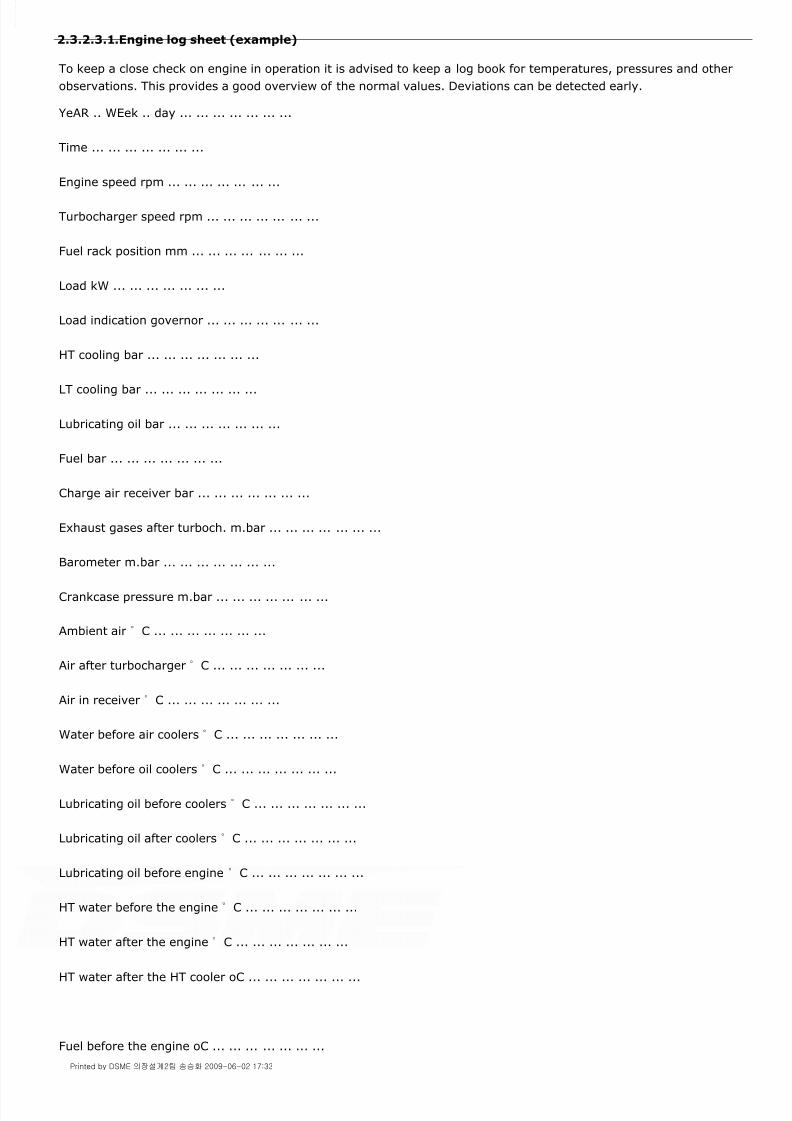
8/9/2019 W26 Instruction Manual
http://slidepdf.com/reader/full/w26-instruction-manual 126/304
P_0000045
2.3.2.3.1.Engine log sheet (example)
To keep a close check on engine in operation it is advised to keep a log book for temperatures, pressures and other
observations. This provides a good overview of the normal values. Deviations can be detected early.
YeAR .. WEek .. day ... ... ... ... ... ... ...
Time ... ... ... ... ... ... ...
Engine speed rpm ... ... ... ... ... ... ...
Turbocharger speed rpm ... ... ... ... ... ... ...
Fuel rack position mm ... ... ... ... ... ... ...
Load kW ... ... ... ... ... ... ...
Load indication governor ... ... ... ... ... ... ...
HT cooling bar ... ... ... ... ... ... ...
LT cooling bar ... ... ... ... ... ... ...
Lubricating oil bar ... ... ... ... ... ... ...
Fuel bar ... ... ... ... ... ... ...
Charge air receiver bar ... ... ... ... ... ... ...
Exhaust gases after turboch. m.bar ... ... ... ... ... ... ...
Barometer m.bar ... ... ... ... ... ... ...
Crankcase pressure m.bar ... ... ... ... ... ... ...
Ambient air °C ... ... ... ... ... ... ...
Air after turbocharger °C ... ... ... ... ... ... ...
Air in receiver °C ... ... ... ... ... ... ...
Water before air coolers °C ... ... ... ... ... ... ...
Water before oil coolers °C ... ... ... ... ... ... ...
Lubricating oil before coolers °C ... ... ... ... ... ... ...
Lubricating oil after coolers °C ... ... ... ... ... ... ...
Lubricating oil before engine °C ... ... ... ... ... ... ...
HT water before the engine °C ... ... ... ... ... ... ...
HT water after the engine °C ... ... ... ... ... ... ...
HT water after the HT cooler oC ... ... ... ... ... ... ...
Fuel before the engine oC ... ... ... ... ... ... ...
Printed by DSME 의장설계2팀 송승화 2009-06-02 17:33

8/9/2019 W26 Instruction Manual
http://slidepdf.com/reader/full/w26-instruction-manual 127/304
P_0000045
Fuel after the engine oC ... ... ... ... ... ... ...
Exhaust gases cyl.1, A1 / B1 oC ./. ./. ./. ./. ./. ./. ./.
" cyl.2, A2 / B2 oC ./. ./. ./. ./. ./. ./. ./.
" cyl.3, A3 / B3 oC ./. ./. ./. ./. ./. ./. ./.
" cyl.4, A4 / B4 oC ./. ./. ./. ./. ./. ./. ./.
" cyl.5, A5 / B5 oC ./. ./. ./. ./. ./. ./. ./.
" cyl.6, A6 / B6 oC ./. ./. ./. ./. ./. ./. ./.
" cyl.7, A7 / B7 oC ./. ./. ./. ./. ./. ./. ./.
" cyl.8, A8 / B8 oC ./. ./. ./. ./. ./. ./. ./.
" cyl.9, A9 / B9 oC ./. ./. ./. ./. ./. ./. ./.
Exhaust gases before turboch. oC ... ... ... ... ... ... ...
Exhaust gases after turboch. oC ... ... ... ... ... ... ...
2.3.2.4.Measurement of cylinder pressure
General
The maximum cylinder pressure is measured with a peak pressure meter connected to the indicator cock on top of the
cylinder head.
The obtained pressure can only be used for comparison with pressures of other cylinders of the engine.
Depending on type of fuel, engine load and rpm, the pressure measured at the indicator cock differs from the
maximum pressure in the cylinder and can be 5-15 bar higher.
Note!
Cylinder pressure measurement at the indicator cock is useful for individually comparison, however, the value
measured is not representative for the real pressure in the combustion space.
More sophisticated instruments can present the cylinder pressure / crank angle diagram showing the start of
combustion and angle of maximum pressure. However, the mean indicated pressure and heat release, as calculated
with these data, does in no way represent the engine performance as measured at the indicator cock.
The obtained data should not be used for this purpose as:
The cylinder pressure indicator is placed at the end of a small bore on top of the cylinder head. In this bore the
pressure is developing steeper giving pressure fluctuations and higher maximum values than in the cylinder space.
Due to length of the indicator channel the pressure pulse is delayed giving a wrong time monitoring.
Note!
It is not permitted to switch off fuel injection of a cylinder to measure compression pressure.
Checking cylinder firing pressure
Check cylinder firing pressures. At the same time record engine load, fuel rack position, turbine speed, charge air
pressure and inlet air temperature. All offer information about the engine performance.
Note!
Printed by DSME 의장설계2팀 송승화 2009-06-02 17:33

8/9/2019 W26 Instruction Manual
http://slidepdf.com/reader/full/w26-instruction-manual 128/304

8/9/2019 W26 Instruction Manual
http://slidepdf.com/reader/full/w26-instruction-manual 129/304

8/9/2019 W26 Instruction Manual
http://slidepdf.com/reader/full/w26-instruction-manual 130/304

8/9/2019 W26 Instruction Manual
http://slidepdf.com/reader/full/w26-instruction-manual 131/304

8/9/2019 W26 Instruction Manual
http://slidepdf.com/reader/full/w26-instruction-manual 132/304
P_0000045
2.3.2.7.Emergency operation
2.3.2.7.1.Operation with defective air cooler(s)
Defective cooling tubes of an air cooler permit cooling water entering the cylinders. Water in the charge air receiver
can be indicated by the condensate drain points. If water or water mist escapes the condensate drain point, check
whether it is cooling water or condensate. If it is condensate, increase the charge air temperature a few degrees (seesection [1.0.4.] ). If it is cooling water, stop the engine as soon as possible and plug off the leaking tube. If cooler
leakage cannot be remedied by tube plugging exchange cooler for a spare. Leaking cooling water is indicated by the
water level in expansion tank.
2.3.2.7.2.Operation with defective turbocharger
A defective turbocharger should be treated in accordance with instructions given in the turbocharger instruction book.
Permissible engine output with blocked turbocharger is approx. 20% load. Engine output must, however, be limited
not to exceed the normal full load exhaust temperatures. Maximum permissible exhaust gas temperature after the
cylinder at continuous operation with blocked turbocharger is 500°C.
2.3.2.7.3.Operation with one cylinder misfiring
A torsional vibration analysis is made for each installation and all possible modes of operation. This is done for as well
normal conditions as for so called misfire conditions.
With misfire conditions we mean: no combustion in one cylinder, only compression and expansion. This can occur due
to for instance a defect HP fuel pump. In case there is also no compression and expansion, Wärtsilä Corporation has to
be consulted.
Eventual restrictions, from point of view of torsional vibration behaviour, mentioned in a torsional vibration analysis
report, have to be obeyed. Otherwise, especially in emergency operation -one cylinder unit out of operation- critical
components as torsional vibration damper, crankshaft, torsional elastic coupling, gearwheel, propeller shaft etcetera,are subjected to not allowable torsional vibration loads.
Note!
Engine operation, with one cylinder misfiring, is only allowed in case restrictions, mentioned in a report concerning
torsional vibration behaviour of this particular installation, are observed!
2.3.3.Engine stop
The engine can always be stopped: remotely, locally or manually.
The local or remote stop involves the following devices:
Stop cylinders on fuel pumps.
Stop signal to actuator controller.
Stop solenoid in actuator (if applicable).
Note!
d) Malfunctioning of actuator. See actuator manual
e) Malfunctioning of actuator drive. .
20. Engine continuous running although stop lever is set in stopposition or remote stop signal is given
.
a) Fuel control mechanism wrongly set (3b, 3c). Activate stop device manually. If enginedoes not stop immediately close fuelsupply to engine.Before restarting problem must be
located and corrected.Risk of overspeed.
b) Malfunction remote engine stop. Use stop lever on engine.
c) Engine is driven by generator, propeller or other source. .
Printed by DSME 의장설계2팀 송승화 2009-06-02 17:33

8/9/2019 W26 Instruction Manual
http://slidepdf.com/reader/full/w26-instruction-manual 133/304
P_0000045
Idle engine 5 - 10 minutes before a normal stop.
Local stop
Push stop button (2) on the local control panel. The engine stops hard wired via the relay module.
Figure 2.3-6: Local stop
Remote stop
Push stop button in the control room, the engine stops electronically.
If applicable, the engine can be stopped by the emergency stop button.
Manual stop
Move stop lever (6) from operating position 'A' into stop position 'B'. Check if pin (7) locks the stop lever.
Figure 2.3-7: Manual stop
Final stop of the engine
For safety reasons open the indicator cocks after final stop of the engine.
Printed by DSME 의장설계2팀 송승화 2009-06-02 17:33
8/9/2019 W26 Instruction Manual
http://slidepdf.com/reader/full/w26-instruction-manual 134/304

8/9/2019 W26 Instruction Manual
http://slidepdf.com/reader/full/w26-instruction-manual 135/304
P_0000045
Last check
2.4.1.2.Maintenance schedule
The total running hours between overhauls as well as the effective life time of components depend generally on the
following aspects:
The operation and maintenance of the engine should be in accordance with instructions as specified in the engine
documentation. The intervals stated in the maintenance schedule are guidance values only, but must not be exceeded during the
guarantee period.
Everyone concerned with the maintenance of the engine should be trained and qualified for the job and should havethe engine documentation available.
To ensure the efficiency, reliability and lifetime of the engine and its components, only genuine spare parts shouldbe used.
The load of the engine should be between 60% and 100% of the output, indicated on the engine type plate, making3,000 to 6,000 running hours annually.
The build on sub-suppliers components should be maintained according the sub-suppliers manufacturersinstructions.
Quality and treatment of lubricating oil, fuel, cooling water and air should be on accordance with the rules.
Deviation from the above factors may result in adapting the running hours between overhauls and/or effective life
time of the components.
2.4.1.2.1.Procedure for inspection and maintenance
Inspection
If, for example, two valve rotators have to be replaced inspect also two rotators of an other cylinder unit. If theresult of this second inspection is also negative replace all valve rotators.
The results of the first 4,000 hours inspection are mend to establish the further service intervals.
Maintenance intervals
15 Before using the hydraulic tools read section [2.4.3.] carefully.
16 For advised glues, lubricants, sealants, see the parts catalogue. Never use other lubricants for bolt
connections of engine components than those advised. Tightening torques will strongly differ if lubricants of
different brand or type are used.
17 Before fitting spare parts, available as complete sub-assemblies, all "O" rings integrated must be inspected
on aging and damage, and replaced if necessary.
18 In general, all piping should be carefully cleaned before installing. Fuel, lubricating oil and air lines should beacid cleaned and neutralized. Also after heating of pipe sections iron oxidation has to be removed by pickling
(acid cleaning).
19 Fit all piping stress free.
20 It is important no tools, parts or other foreign matters have been left in or on the engine and all parts have
been thoroughly cleaned before closing the engine.
21 Due to the compression ability of some gasket material the prestress of some flange connections should be
checked after 24 hours of operation.
22 Record engine parts renewed.
23 Record engine running hours.
General
Every
(running hours)
Printed by DSME 의장설계2팀 송승화 2009-06-02 17:34

8/9/2019 W26 Instruction Manual
http://slidepdf.com/reader/full/w26-instruction-manual 136/304

8/9/2019 W26 Instruction Manual
http://slidepdf.com/reader/full/w26-instruction-manual 137/304
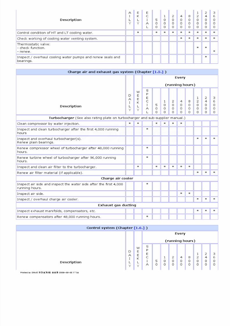
8/9/2019 W26 Instruction Manual
http://slidepdf.com/reader/full/w26-instruction-manual 138/304
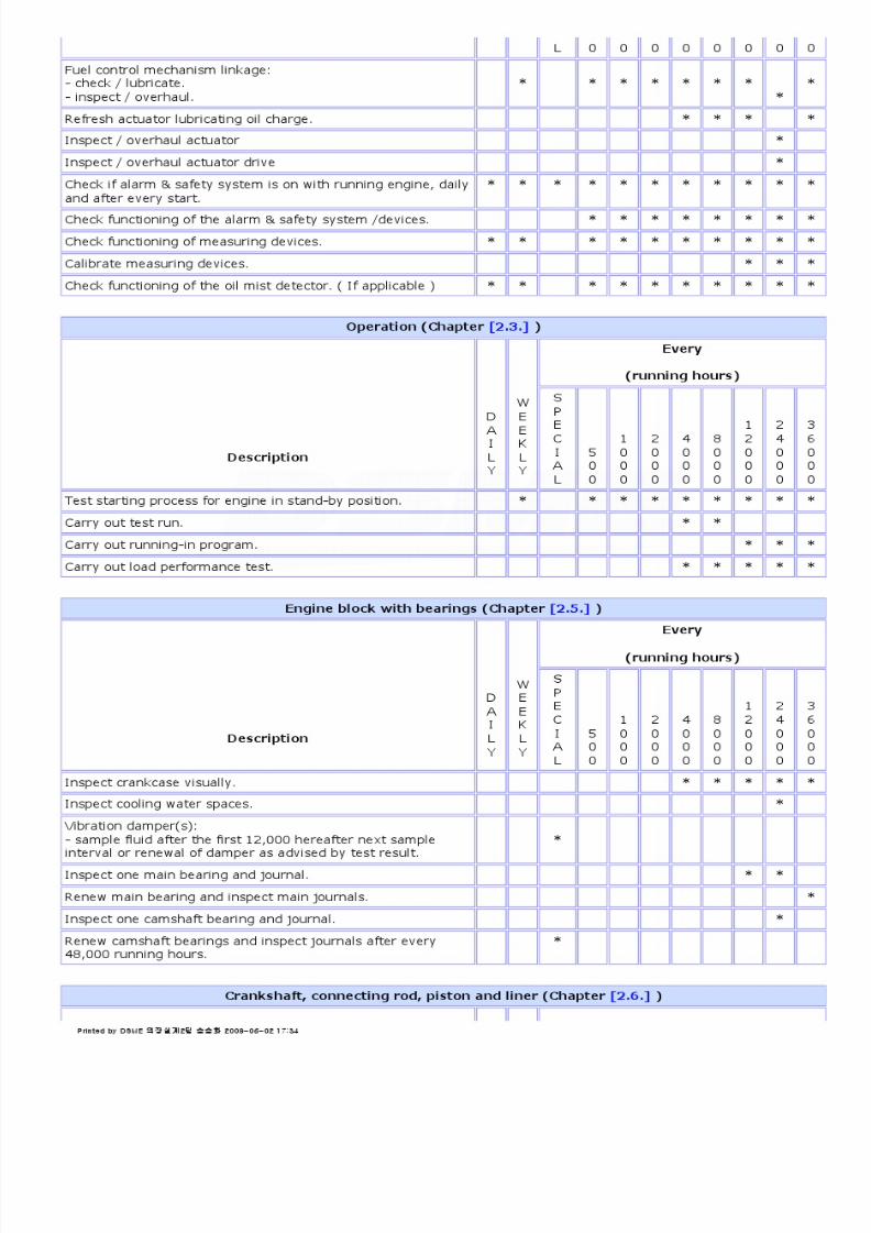
8/9/2019 W26 Instruction Manual
http://slidepdf.com/reader/full/w26-instruction-manual 139/304

8/9/2019 W26 Instruction Manual
http://slidepdf.com/reader/full/w26-instruction-manual 140/304

8/9/2019 W26 Instruction Manual
http://slidepdf.com/reader/full/w26-instruction-manual 141/304

8/9/2019 W26 Instruction Manual
http://slidepdf.com/reader/full/w26-instruction-manual 142/304
P_0000045
2.4.2.Maintenance Tools
Maintenance of a diesel engine requires a number of special tools developed in the course of engine design. Some of
these tools are supplied with the engine and others are available through our service stations or for direct purchase by
the customer.
Tool requirements for a particular installation may vary greatly depending on the use and service area. Special tools
are therefore selected to meet basic requirements.
This section shows a selection of tools for the engine.
These tools are not all described in the related sections.
The tools are grouped in order to facilitate selection for specific service operations.
Miscellaneous tools, as mentioned in section [2.4.2.1.] , are used in various chapters.
Tools for instance needed for cylinder head are grouped in section [2.4.2.7.] The chapter mentioned between brackets
refers to the chapter where these tools are used.
Depending on the scope of supply the following tool sets are available:
1. Tool set for restricted area "Economic Set"
2. Tool set for unrestricted area "Standard Set"
3. Extended tool set for restricted area "Extended Set"
4. Extra extended tool set restricted area "Workshop Set"
5. Special tools "Special Tool Set"
1. "Economic Set" Article number [9612ZT991] A
Tool set [9612ZT991] A consists of the following articles:
Article number Description Number
[9612ZT901] Hydraulic jack 2
[9612DT381] Hydraulic hose 2
[9612ZT992] Hydraulic hand pump 1
[9612ZT927] Lifting tool cylinder head 1
[9612ZT904] Tie rod + distance piece cylinder head 2
[9612ZT255] Socket HP fuel connecting pipe 1
[9612DT259] Socket for injector sleeve nut 1
[9612ZT940] Depth gauge 1
[9612ZT978] Holder for fuel injector 1
[9612ZT913] Hydraulic jack 1
[9612ZT919] Compress tool valve springs 1
[9612DT260] Multiplier max 1700 Nm 1
[9622DT216] Torque wrench 150-800 Nm 1
[9622DT215] Torque wrench 70-350 Nm 1
[9612ZT931] Extractor fuel injector 1
[9612ZT934] Testing device fuel injector 1
Printed by DSME 의장설계2팀 송승화 2009-06-02 17:34
8/9/2019 W26 Instruction Manual
http://slidepdf.com/reader/full/w26-instruction-manual 143/304
P_0000045
[9650ZT108] Adjusting spanner injector 1
[9612ZT187] Spanner for plug injector 1
[9612ZT251] Feeler gauge for valve adjusting 2
[9612SW510] T-bar wrench 8mm 1
[9622DT214] Torque wrench 20-100 Nm 1
[9612ZT331] Crow foot spanner 1
[9612ZT332] Extension with spline for multiduct 1
[9612ZT962] Grinding tool seat injector cylinder head 1
2. "Standard Set" Article number [9612ZT992] A
Consists of:
"Economic set" [9612ZT991] A extended with tool set [9612ZT893] .
Tool set [9612ZT893] consits of the following articles:
Article number Description Number
[9612ZT185] Piston ring pliers 1
[9612ZT195] Tap M8 1
[9612ZT250] Circlip pliers 1
[9612ZT334] Air tool 3/8" 1
[9612ZT445] Mounting unit 1
[9612ZT902] Tie rod + distance piece side stud 2
[9612ZT903] Tie rod + distance piece main bearing cap 2
[9612ZT906] Trolley for main bearing 1
[9612ZT910] Bearing shell driver 1
[9612ZT911] Mounting tool cylinder liner 1
[9612ZT912] Extractor cylinder liner 1
[9612ZT917] Piston ring tool 1
[9612ZT935] Stud remover main bearing / cylinder head 1
[9612ZT938] Piston support 1
[9612ZT941] Depth gauge 1
[9612ZT944] Hydraulic jack connecting rod 2
[9612ZT950] Polishing ring 1
[9612ZT951] Polishing ring 1
[9612ZT877] Extractor cooling water pipe to cylinder head 1
[9612ZT256] Sleeve for cylinder liner fixation 2
[9612ZT856] Dummy counter weight 1
[9612ZT924] Locking ring 4
[9612ZT925] Locking ring 2
Printed by DSME 의장설계2팀 송승화 2009-06-02 17:34

8/9/2019 W26 Instruction Manual
http://slidepdf.com/reader/full/w26-instruction-manual 144/304
P_0000045
3. "Extended Set" Article number [9612ZT994] A
Consits of:
"Standard Set" [9612ZT992] A extended with toolset [9612ZT892]
Toolset [9612ZT892] consists of the following articles:
Article number Description Number
[9612ZT247] Disc 2
[9612ZT380] Pneumatic/hydraulic pump 1400 bar 1
[9612ZT376] Crowbar 1
[9612ZT901] Hydraulic jack 2
[9612ZT915] Tool polishing ring 1
[9612ZT918] Distributing block 2
[9612ZT952] Dis/assembling tool connecting rod cap V 1
[9612ZT936] Stud remover connecting rod 1
[9612ZT942] Frame and jacks cylinder head 1
[9612ZT947] Tool support ring valve spring 1
[9612ZT953] Assembly tool joint washer 1
[9612ZT956] Tool for valve rotator 1
[9612ZT969] Protecting bearing journal V 2
[9612ZT975] Spare set "O & backup" rings 1
[9612DT373] Hydraulic hose 4
4. "Workshop Set" Article numbers [9612ZT995] A + [9612ZT997] B
Tool set [9612ZT995] A consists of tool sets [9612ZT994] A + [9612ZT894] .
Tool set [9612ZT894] consists of the following articles:
Article number Description Number
[9612ZT971] Dis/assembling fuel pump 1
[9612ZT945] Tool for valve seat 1
[9612ZT233] Mounting tool valve guide 1
[9612ZT234] Mounting tool pin bridge piece 1
[9612ZT946] Mounting tool injector sleeve 1
[9612ZT961] Lifting tool bracket fuel pump 1
[9612ZT225] Pin 1
[9612ZT497] Spanner for vibration damper 1
[9612ZT547] Depth gauge 1
[9612ZT377] Pressing punch 2
Printed by DSME 의장설계2팀 송승화 2009-06-02 17:34

8/9/2019 W26 Instruction Manual
http://slidepdf.com/reader/full/w26-instruction-manual 145/304

8/9/2019 W26 Instruction Manual
http://slidepdf.com/reader/full/w26-instruction-manual 146/304
P_0000045
[9622DT941] Peak pressure gauge 0-220 bar 1
[9622DT942] Peak pressure gauge digital 1
[9622DT943] Noncontact thermometer 1
[9622DT944] Crankshaft deflection gauge 1
[9622DT945] Digital crankshaft deflection gauge 1
[9622DT946] Hand tachometer digital 1
[9612ZT353] Micrometer 1
[9612ZT365] Inside micrometer 1
[9612ZT973] Transport case piston-unit 1
[9612ZT865] Pneumatic calibration tool fuel pump 1
[9622DT936] Tool set box 1
[9622DT275] Magnetic stand + Dial indicator 1
[9612ZT867] Mechanic stethoscope 1
[9612ZT868] Endoscope 1
[9612ZT870] Honing machine cylinder liner 1
[9622DT969] Service box for oil mist detector 1
[9612ZT879] Pneumatic atomizer test unit 1
[9612ZT871] Control tools for WECS 1
2.4.2.1.Miscellaneous tools
Description Code number Weightkg
Dimensions
Hydraulic pump (air operated). [9612ZT380] .
.
Description Code number Weightkg
Dimensions
Hydraulic pump (manuallyoperated).
[9612ZT992] .
.
Description Code number Weightkg
Dimensions
Hydraulic jack (3). [9612ZT901] .
Printed by DSME 의장설계2팀 송승화 2009-06-02 17:34

8/9/2019 W26 Instruction Manual
http://slidepdf.com/reader/full/w26-instruction-manual 147/304
P_0000045
With:
1. Knurled nut2. Tool pin.
Used for:- main bearing studs- side studs- cylinder head studs.
[9612ZT119] [9612ZT125]
.
Description Code number Weightkg
Dimensions
Hydraulic jack.
Used in combination
with:- camshaft bearingbush extractor
- valve removing /mounting tool.- extractor forcylinder liner.
[9612ZT913]
[9612ZT850]
[9612ZT919]
[9612ZT912]
.
.
Description Code number Weightkg
Dimensions
HP hose. [9612DT381] .
.
Description Code number Weight
kg
Dimensions
Distribution block HP hoses. [9612ZT918] .
.
Description Code number Weightkg
Dimensions
Hydraulic hose. [9612DT373] .
Printed by DSME 의장설계2팀 송승화 2009-06-02 17:34
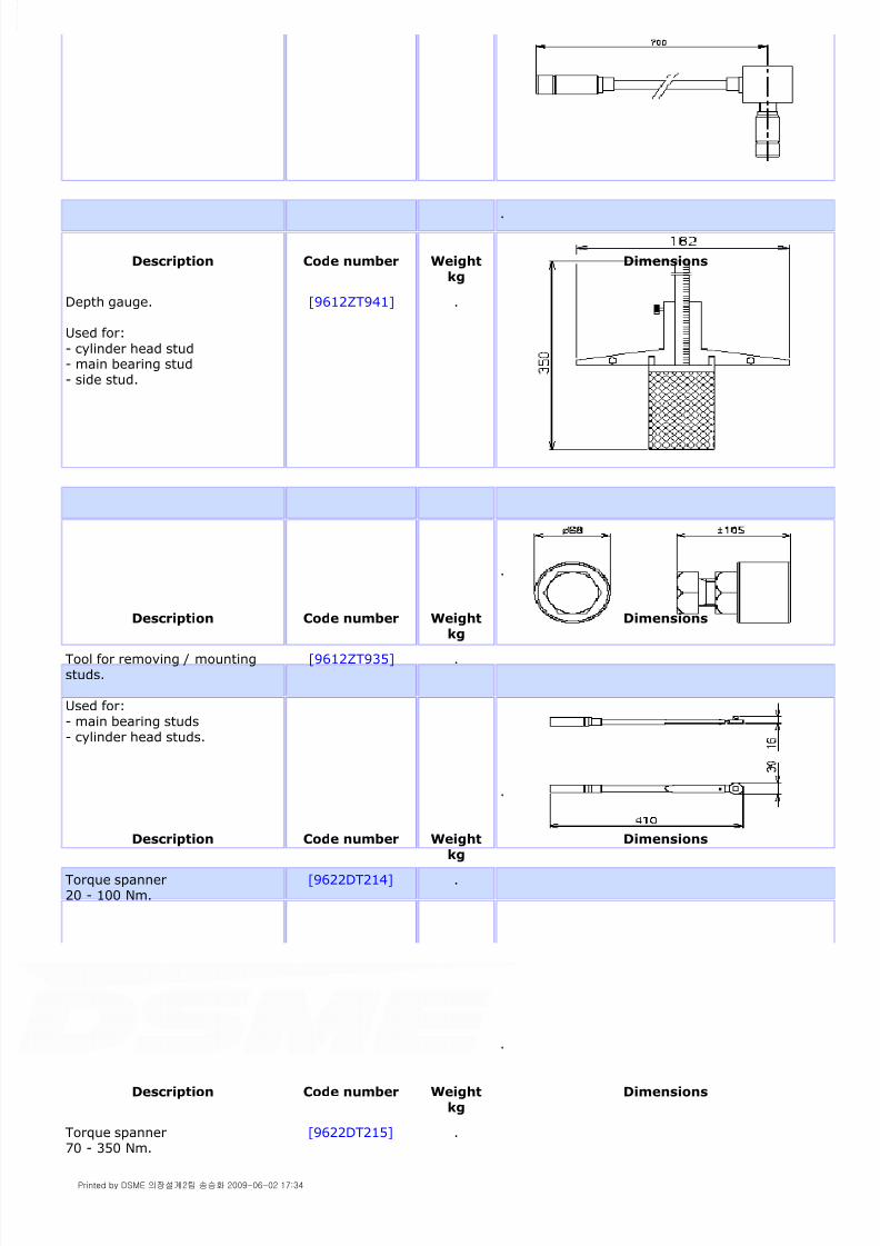
8/9/2019 W26 Instruction Manual
http://slidepdf.com/reader/full/w26-instruction-manual 148/304
P_0000045
.
Description Code number Weightkg
Dimensions
Depth gauge.
Used for:
- cylinder head stud- main bearing stud- side stud.
[9612ZT941] .
.
Description Code number Weight
kg
Dimensions
Tool for removing / mountingstuds.
Used for:- main bearing studs- cylinder head studs.
[9612ZT935] .
.
Description Code number Weightkg Dimensions
Torque spanner20 - 100 Nm.
[9622DT214] .
.
Description Code number Weightkg
Dimensions
Torque spanner70 - 350 Nm.
[9622DT215] .
Printed by DSME 의장설계2팀 송승화 2009-06-02 17:34

8/9/2019 W26 Instruction Manual
http://slidepdf.com/reader/full/w26-instruction-manual 149/304
P_0000045
2.4.2.2.Fuel system
(Chapter [1.1.] )
.
Description Code number Weightkg
Dimensions
Torque spanner
150 - 800 Nm.
[9622DT216] .
.
Description Code number Weightkg
Dimensions
Lifting tool fuel pump bracket. [9612ZT961] .
.
Description Code number Weightkg
Dimensions
Tool for HP fuel pump
tappet.
Used in combinationwith:- HP hose- hydraulic pump.
[9612ZT960]
[9612DT381] [9612ZT992]
.
Printed by DSME 의장설계2팀 송승화 2009-06-02 17:34

8/9/2019 W26 Instruction Manual
http://slidepdf.com/reader/full/w26-instruction-manual 150/304
P_0000045
.
Description Code number Weightkg
Dimensions
Locking tool for HP fuel pump
tappet.
[9612ZT925] .
.
Description Code number Weight
kg
Dimensions
Tool for sealing set in HP fuelpump bracket.
[9612ZT953] .
.
Description Code number Weightkg
Dimensions
Depth gauge for fuel pump pushrods.
[9612ZT547] .
Printed by DSME 의장설계2팀 송승화 2009-06-02 17:34

8/9/2019 W26 Instruction Manual
http://slidepdf.com/reader/full/w26-instruction-manual 151/304

8/9/2019 W26 Instruction Manual
http://slidepdf.com/reader/full/w26-instruction-manual 152/304

8/9/2019 W26 Instruction Manual
http://slidepdf.com/reader/full/w26-instruction-manual 153/304
P_0000045
1. girder
2. top plate3. support4. lifting tool.
[9612ZT261]
[9612ZT262] [9612ZT263] [9612ZT267]
.
Description Code number Weightkg
Dimensions
Bearing shell driver. [9612ZT910] .
.
Description Code number Weightkg
Dimensions
Air driven rachet.
Used for:
- main bearing lifting tool.
[9612ZT334]
[9612ZT267]
.
.
Description Code number Weightkg
Dimensions
Extractor for camshaftbearing bush.
Consisting of:1. disc2. support disc
3. disc axial bearingbush4. support disc foraxial bearing bush.
Used in combinationwith:
[9612ZT850]
[9612ZT545] [9612ZT546]
[9612ZT153]
[9612ZT154]
.
Printed by DSME 의장설계2팀 송승화 2009-06-02 17:34

8/9/2019 W26 Instruction Manual
http://slidepdf.com/reader/full/w26-instruction-manual 154/304
P_0000045
5. hydraulic jack. [9612ZT913]
.
Description Code number Weightkg
Dimensions
Tool for mounting camshaft axialbearing bushes.
[9612ZT948] .
.
Description Code number Weightkg
Dimensions
Sleeve for cylinder liner fixation. [9612ZT256] .
.
Description Code number Weightkg
Dimensions
Positioning pin for camshaft [9612ZT194] .
Printed by DSME 의장설계2팀 송승화 2009-06-02 17:34

8/9/2019 W26 Instruction Manual
http://slidepdf.com/reader/full/w26-instruction-manual 155/304
P_0000045
2.4.2.6.Crankshaft, connecting rod, piston and liner
(Chapter [2.6.] )
bearing bush.
.
Description Code number Weightkg
Dimensions
Polishing ring.
Used for:
- contact surface oncylinder block for liner- cylinder head gassealing surface.
[9612ZT950] .
.
Description Code number Weightkg
Dimensions
Depth gauge for connecting rodstuds.
[9612ZT940] .
.
Description Code number Weightkg
Dimensions
Extractor anti bore polishingring.
[9612ZT915] .
Printed by DSME 의장설계2팀 송승화 2009-06-02 17:34

8/9/2019 W26 Instruction Manual
http://slidepdf.com/reader/full/w26-instruction-manual 156/304
P_0000045
.
Description Code number Weightkg
Dimensions
Tool set for big end
bearing stud.
Consisting of:1. hydraulic jack2. tie rod3. knurled nut4 tool pin
[9612ZT944]
[9612ZT476] [9612ZT477] [9612ZT125]
.
.
Description Code number Weightkg
Dimensions
Tool connecting rod cap. [9612ZT952] .
.
Description Code number Weightkg
Dimensions
Lifting tool for connectingrod/piston/liner assembly(driving unit).
Consisting of:
[9612ZT911] .
Printed by DSME 의장설계2팀 송승화 2009-06-02 17:34

8/9/2019 W26 Instruction Manual
http://slidepdf.com/reader/full/w26-instruction-manual 157/304
P_0000045
1. protecting sleeves
2. positioning bracket3. protecting sleeves.
[9612ZT114]
[9612ZT113] [9612ZT112]
.
Description Code number Weightkg
Dimensions
Extractor for cylinderliner.
Consisting of:1. tie rod2. ring3. nut4. bracket.
Used in combinationwith:- lifting tool.- jack.
[9612ZT912]
[9612ZT160] 0350 007
[9612ZT156] [9612ZT159]
[9612ZT911] [9612ZT913]
.
.
Description Code number Weightkg
Dimensions
Tap M8 for threaded holes inpiston crown.
[9612ZT195] .
.
Description Code number Weightkg
Dimensions
Pliers for locking ring gudgeonpin.
[9612ZT250] .
.
Description Code number Weightkg
Dimensions
Piston ring pliers. [9612ZT185] .
Printed by DSME 의장설계2팀 송승화 2009-06-02 17:34

8/9/2019 W26 Instruction Manual
http://slidepdf.com/reader/full/w26-instruction-manual 158/304
P_0000045
.
Description Code number Weightkg
Dimensions
Clamp for piston rings. [9612ZT917] .
.
Description Code number Weightkg
Dimensions
Tool for removing / mountingconnecting rod studs.
[9612ZT936] .
.
Description Code number Weight
kg
Dimensions
Tilting frame for connecting rod /
piston / liner assembly (drivingunit).
[9612ZT954] .
Printed by DSME 의장설계2팀 송승화 2009-06-02 17:34

8/9/2019 W26 Instruction Manual
http://slidepdf.com/reader/full/w26-instruction-manual 159/304
P_0000045
.
Description Code number Weightkg
Dimensions
Piston support. [9612ZT938] .
.
Description Code number Weightkg
Dimensions
Lever for checking axialclearance crankshaft.
[9612ZT376] .
.
Description Code number Weightkg
Dimensions
Support for connectingrod/piston assembly (drivingunit).
[9612ZT445] .
.
Description Code number Weight
kg
Dimensions
Polishing ring for gas sealingsurface cylinder liner top.
[9612ZT951] .
Printed by DSME 의장설계2팀 송승화 2009-06-02 17:34

8/9/2019 W26 Instruction Manual
http://slidepdf.com/reader/full/w26-instruction-manual 160/304
P_0000045
.
Description Code number Weightkg
Dimensions
Crankshaft protecting sheet. [9612ZT969] .
.
Description Code number Weightkg
Dimensions
Dummy counter weight. [9612ZT856] .
.
Description Code number Weightkg
Dimensions
Spanner for sampling plugvibration damper.
[9612ZT497] .
.
Description Code number Weightkg
Dimensions
Multiplier,
max. 6200 Nm.
[9612ZT979] .
Printed by DSME 의장설계2팀 송승화 2009-06-02 17:34

8/9/2019 W26 Instruction Manual
http://slidepdf.com/reader/full/w26-instruction-manual 161/304
P_0000045
2.4.2.7.Cylinder head with valves
(Chapter [2.7.] )
Used for:- crankshaft vibrationdamper.
.
Description Code number Weightkg
Dimensions
Feeler gauge for valve clearance. [9612ZT251] .
.
Description Code number Weightkg
Dimensions
Extension with spline for
cylinder head - multiductconnection.
Used in combination
with:- torque spanner.
[9612ZT332]
[9622DT215]
.
.
Description Code number Weight
kg
Dimensions
Tool set for cylinder head
Consisting of:
1. frame2. shackle3. hydraulic jack
[9612ZT942]
[9612ZT197] [9612ZT198] [9612ZT901]
.
Printed by DSME 의장설계2팀 송승화 2009-06-02 17:34

8/9/2019 W26 Instruction Manual
http://slidepdf.com/reader/full/w26-instruction-manual 162/304
P_0000045
4. tie rod and distance piece [9612ZT904]
.
Description Code number Weightkg
Dimensions
Tie rod and distancepiece
Consisting of:1. tie rod2. distance piece
Used in combinationwith:- hydraulic jackincluding:- knurled nut- tool pin.
[9612ZT904]
[9612ZT131] [9612ZT196]
[9612ZT901]
.
.
Description Code number Weightkg
Dimensions
Lifting tool for cylinder head. [9612ZT927] .
.
Description Code number Weightkg
Dimensions
Tilting frame for cylinder head. [9612ZT958] .
Printed by DSME 의장설계2팀 송승화 2009-06-02 17:34

8/9/2019 W26 Instruction Manual
http://slidepdf.com/reader/full/w26-instruction-manual 163/304
P_0000045
.
Description Code number Weightkg
Dimensions
Tool set for removing / mountingvalves.
Consisting of:1. pressing plate MDO2. pressing plate HFO.
Used in combinationwith:- jack.
[9612ZT919]
[9612ZT145] [9612ZT184]
[9612ZT913]
.
.
Description Code number Weightkg
Dimensions
Tool for exhaust valve rotator.
Used only for:? HFO engines.
[9612ZT956] .
.
Description Code number Weightkg
Dimensions
Tool support ring valve spring. [9612ZT947] .
Printed by DSME 의장설계2팀 송승화 2009-06-02 17:34

8/9/2019 W26 Instruction Manual
http://slidepdf.com/reader/full/w26-instruction-manual 164/304
P_0000045
.
Description Code number Weightkg
Dimensions
Extractor valve guide. [9612ZT909] .
.
Description Code number Weightkg
Dimensions
Mounting tool valve guides. [9612ZT233] .
.
Description Code number Weightkg
Dimensions
Extractor exhaust valve seat. [9612ZT859] .
Printed by DSME 의장설계2팀 송승화 2009-06-02 17:34

8/9/2019 W26 Instruction Manual
http://slidepdf.com/reader/full/w26-instruction-manual 165/304
P_0000045
.
Description Code number Weightkg
Dimensions
Mounting tool valve seat. [9612ZT945] .
.
Description Code number Weightkg
Dimensions
Tool for refacing valve seats. [9612ZT863] .
.
Description Code number Weightkg Dimensions
Extractor injector sleeve. [9612ZT932] .
Printed by DSME 의장설계2팀 송승화 2009-06-02 17:34
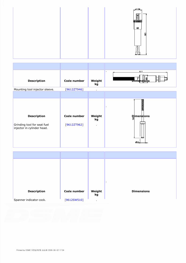
8/9/2019 W26 Instruction Manual
http://slidepdf.com/reader/full/w26-instruction-manual 166/304
P_0000045
.
Description Code number Weightkg
Dimensions
Mounting tool injector sleeve. [9612ZT946] .
.
Description Code number Weightkg
Dimensions
Grinding tool for seat fuel
injector in cylinder head.
[9612ZT962] .
.
Description Code number Weightkg
Dimensions
Spanner indicator cock. [9612SW510] .
Printed by DSME 의장설계2팀 송승화 2009-06-02 17:34

8/9/2019 W26 Instruction Manual
http://slidepdf.com/reader/full/w26-instruction-manual 167/304
P_0000045
2.4.2.8.Camshaft and valve drive mechanism
(Chapter [2.8.] )
.
Description Code number Weightkg
Dimensions
Cylinder liner cover (wood). [9612ZT247] .
.
Description Code number Weightkg
Dimensions
Extractor cooling waterinterconnecting pipe. [9612ZT877] .
.
Description Code number Weightkg
Dimensions
Ratchet spanner for camshaftsection bolts.
[9612ZT560] .
.
Description Code number Weight Dimensions
Printed by DSME 의장설계2팀 송승화 2009-06-02 17:34

8/9/2019 W26 Instruction Manual
http://slidepdf.com/reader/full/w26-instruction-manual 168/304
P_0000045
kg
Torque wrench for camshaftsection bolts.20 - 200 Nm.
Consisting of:1. torque wrench2. bit holder3. screwdriver bit.
[9612ZT558] .
.
Description Code number Weight
kg
Dimensions
Locking tool for tappets inlet andexhaust.
[9612ZT924] .
.
Description Code number Weightkg
Dimensions
Tool for separating camshaftsection from journal.
Consisting of:1. Bolt M12 / 40 mm2. Bolt M12 / 80 mm3. Retainer nut
[9612ZT377] .
.
Description Code number Weightkg
Dimensions
Support for camshaft journal. [9612ZT987] .
Printed by DSME 의장설계2팀 송승화 2009-06-02 17:34
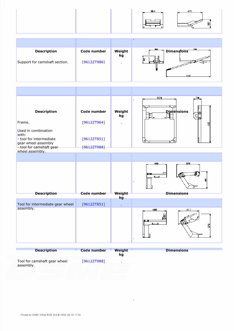
8/9/2019 W26 Instruction Manual
http://slidepdf.com/reader/full/w26-instruction-manual 169/304
P_0000045
.
Description Code number Weight
kg
Dimensions
Support for camshaft section. [9612ZT986] .
.
Description Code number Weightkg
Dimensions
Frame.
Used in combinationwith:- tool for intermediategear wheel assembly- tool for camshaft gearwheel assembly.
[9612ZT964]
[9612ZT851]
[9612ZT988]
.
.
Description Code number Weightkg
Dimensions
Tool for intermediate gear wheelassembly.
[9612ZT851] .
.
Description Code number Weightkg
Dimensions
Tool for camshaft gear wheelassembly.
[9612ZT988] .
.
Printed by DSME 의장설계2팀 송승화 2009-06-02 17:34

8/9/2019 W26 Instruction Manual
http://slidepdf.com/reader/full/w26-instruction-manual 170/304
P_0000045
2.4.2.9.Injection system
(Chapter [2.9.] )
Description Code number Weightkg
Dimensions
Secure tool camshaft. [9612ZT855] .
.
Description Code number Weight
kg
Dimensions
Hydraulic nipple camshaftgearwheel.
[9612ZT864] .
.
Description Code number Weightkg
Dimensions
Tool for separating camshaft end journal from camshaft gearwheel.
[9612ZT982] .
.
Printed by DSME 의장설계2팀 송승화 2009-06-02 17:34

8/9/2019 W26 Instruction Manual
http://slidepdf.com/reader/full/w26-instruction-manual 171/304
P_0000045
Description Code number Weight
kg
Dimensions
Socket spanner for HPfuel pipe in cylinderhead.
Used in combinationwith:- torque spanner
[9612ZT255]
[9622DT215]
.
.
Description Code number Weight
kg
Dimensions
Crow foot spannerHP fuel pipe.
Used in combinationwith:- torque spanner
[9612ZT331]
[9622DT215]
.
.
Description Code number Weightkg
Dimensions
Tool for extracting fuelinjector.
1. handle.
2. nut.3. bush.
[9612ZT931]
[9612ZT178]
.
.
Description Code number Weightkg
Dimensions
Holder for fuel injector.
Used in combinationwith:
[9612ZT978] .
Printed by DSME 의장설계2팀 송승화 2009-06-02 17:34

8/9/2019 W26 Instruction Manual
http://slidepdf.com/reader/full/w26-instruction-manual 172/304
P_0000045
- torque spanner
- multiplier- socket spanner.
[9622DT216]
[9612DT260] [9612ZT259]
.
Description Code number Weightkg
Dimensions
Multiplier,max. 1700 Nm.
Used in combinationwith:- socket spanner- torque spanner- holder for fuel injector.
[9612DT260]
[9612DT259] [9622DT216] [9612ZT978]
.
.
Description Code number Weightkg
Dimensions
Testing device fuel injector. [9612ZT934] .
.
Description Code number Weight
kg
Dimensions
Tool for disassembling /assembling HP fuel pump.
[9612ZT971] .
Printed by DSME 의장설계2팀 송승화 2009-06-02 17:34

8/9/2019 W26 Instruction Manual
http://slidepdf.com/reader/full/w26-instruction-manual 173/304
P_0000045
.
Description Code number Weightkg
Dimensions
Socket spanner forinjector sleeve nut.
Used in combinationwith:- torque spanner
- multiplier- holder for fuel injector.
[9612DT259]
[9622DT216]
[9612DT260] [9612ZT978]
.
.
Description Code number Weightkg
Dimensions
Spanner for plug fuel injector. [9612ZT187] .
.
Description Code number Weight
kg
Dimensions
Adjusting tool fuel injector. [9650ZT108] .
Printed by DSME 의장설계2팀 송승화 2009-06-02 17:34

8/9/2019 W26 Instruction Manual
http://slidepdf.com/reader/full/w26-instruction-manual 174/304
P_0000045
2.4.3.Background information of hydraulic tools and torque spanners
A number of important engine components are fitted by means of hydraulic tools. With the use of hydraulic tools is it
possible to stress a bold or stud of a connection till very high tension. This tightening process can be done within very
small tension limits and a great force and accuracy.
It is necessary to understand the working principle of the hydraulic tools. For this reason an explanation of the
principle is given.
For safety reasons it is important the tools are used in the correct way.
The tightening procedures have to be carried out strictly in accordance with the instructions in this manual.
For the following subjects general background information is described:
"Rolled thread"
The thread of the studs of important connections is manufactured by a "cold rolled" process to make the stud threadstrong and good resistant against fatigue. Due to this process the circumference of the thread becomes smooth and
hard. This process make studs also sensitive to breakage in case of damage. Therefore, studs must always carefully be
handled. Replace a stud when damaged.
The "easy going" nut
The stud becomes a little bit longer over its entire length during elongation. This includes that also the pitch of the
thread is a little extended. However, the pitch of the nut mounted is not extended. To make it possible to turn the nut
on the elongated stud "quite some clearance" must exist between the thread of the nut and the thread of the stud.
This clearance can be felt when turning on the nut. For this reason it must be possible, without any restriction, to turn
on a nut by hand.
In case of "heavy points" remove the nut and find and solve the problem before starting the tightening procedure.
Studs
All hydraulically stretched studs are made of high tensile strength steel. To obtain the correct force in the studs, the
studs have to be stretched to approximately 90% of the yield point of the material.
.
Description Code number Weightkg
Dimensions
Synthetic driver for HP fuelpump barrel.
[9612ZT225] .
.
Printed by DSME 의장설계2팀 송승화 2009-06-02 17:34

8/9/2019 W26 Instruction Manual
http://slidepdf.com/reader/full/w26-instruction-manual 175/304
P_0000045
This means, a force 10% more than the tightening force does overstretch the stud. This may never happen because
over- stretched studs becomes sensitive to fatigue and may break after some time.
Therefore, overstretched studs should be replaced. This is particular important for connecting rod studs and counter
weight studs.
Use genuine parts
There is a real danger in employing studs not delivered by Wärtsilä Corporation in particular studs hydraulically
stretched.
If these studs are not made from the same high tensile strength material and not provided with "cold rolled thread",
problems may occur. Studs, made of material not sufficient strong, will continue to elongate even if the correct oil
pressure is applied. The nuts can be turned further until breaking.
Use of locking fluids
Clean parts carefully with a degreasing agent and dry parts before applying locking fluid.
Note!
See for specification relevant drawing / parts list (Parts Catalogue).
The hydraulic tool set consist of :
Hydraulic pump pneumatically driven or a manually operated pump.
A number of hydraulic jacks, distance pieces, tie rods, knurled nuts, high pressure hoses with quick release couplingand tool pins to tighten or to loosen the nuts of the relevant components.
2.4.3.1.Pneumatic driven hydraulic pump unit
The pump unit ( [fig. 2.4-1] ) consist of a number of main components:
A connection (7) for the supply of service air (maximum pressure 7 bar.
A filter / water separator (12). A lubricator (13).
A reducing valve (6) to adjust the service air between 0 and 6 bar.
A manometer (5) direct mounted after the service air reducing valve.
An air valve (4) to control the pump speed.
An air-operated piston (3) (large surface) connected to a piston in the lower section (small surface) for pressurizing
the hydraulic oil.
A container (1) for hydraulic oil (circa 5 litres).
A double pointer manometer (8) indicating the hydraulic jack pressure.
A quick-release couplings with non return valve (10).
A valve (9) in the H.P. oil return line.
The manometer (5) is connected to the air pressure line after the reducing valve (6). The manometer scale indicates a
comparable oil pressure from 0 to 1000 bar. 6 Bar service air pressure is equivalent to 1000 bar "oil pressure" on the
manometer scale. The manometer (5) makes it possible to set the required H.P. oil pressure before pumping.
To prevent, due to inaccuracy of this manometer, that the final obtained oil pressure will ends higher than the required
pressure, manometer (5) indicates 10% higher.
A manometer (8) indicates the pressure in the H.P. hydraulic system.
This calibrated manometer contains two independently working measuring mechanisms, each provided with a scale
and pointer. Recalibrating of this manometer is necessary when the indication of both pointers differs more then 10
bar.
Check the double pointer pressure gauge (8) regularly. For this purpose a calibrated pressure gauge can be delivered.
This pressure gauge can be connected at the end of the H.P. hose.
Printed by DSME 의장설계2팀 송승화 2009-06-02 17:34

8/9/2019 W26 Instruction Manual
http://slidepdf.com/reader/full/w26-instruction-manual 176/304
P_0000045
Figure 2.4-1: Diagram pneumatically driven hydraulic pump unit
Operating
Always keep the pump unit horizontally. Maintain sufficiently hydraulic oil in the container to avoid air in the system
and check if valve (14) is open.
During filling of the H.P. pump container, it is recommended to connect the set according to [Fig. 2.4-2] . Before
filling, open the release valve (9) and empty the jack (15) by pressing piston and cylinder simultaneously. Next, the
container can be filled through the filling plug (2). (For specification of the hydraulic oil, see chapter [1.2.] ).
Every time the pump is operated, the pressure will rise automatically and accurately till the fixed pump setting
(accuracy ± 5 bar). When the hydraulic stretching procedure is completed close valve (4) and always open slowly
valve (9). Quick opening of valve (4) may damage the hydraulic pressure manometer.
Remark
1 Close valves (4) and (9), see fig 2.4 - 1 and [fig. 2.4-2] .
2 Connect at (10) the H.P. hose (11) to the hydraulic jacks (15).
3 Connect the service air at (7).
4 After adjusting the "air pressure" at the value of the required oil pressure, start the pump by opening air
valve (4). The hydraulic system will be pressurized, visible on manometer (8). At a value of approx. 10% below
the adjusted value, the pump will stop.
5 Slowly turn the spindle of the reducing valve (6) counter clockwise, by which the hydraulic oil pressure will
increase.
6 Continue pumping until the reading on the manometer of the hydraulic system (8) shows the required oil
pressure. The manometer in the air system will now show a pressure of circa 10 % higher.
7 After the correct oil pressure has been reached, push down the locking ring over the reducing valve spindle to
fix the setting of the reducing valve.
Printed by DSME 의장설계2팀 송승화 2009-06-02 17:34

8/9/2019 W26 Instruction Manual
http://slidepdf.com/reader/full/w26-instruction-manual 177/304
P_0000045
When the required pressure is reached and the pump continues slowly working, the hydraulic system is leaking, e.g. a
leaking coupling or a leaking hydraulic jack.
When the hydraulic system contains air, disconnect the coupling at (10).
Press the small valve in the coupling by means of a pin and run the pump slowly. Let oil escape as long as it contains
air.
Warning!
Always check the correct connecting of hose couplings to pump unit and jacks special when more jacks are connected
at the time. An incorrectly made connection may cause the jack is not connected and the jack in question not
pressurized although the manometer indicates the correct pressure.
Figure 2.4-2: Pneumatic driven hydraulic pump unit
2.4.3.2.Hydraulic jack
A hydraulic jack, see [fig. 2.4-3] for an example, consists basically of a housing (3) and a piston (1) which is
accommodated in a recess in the top of the housing. The piston is sealed at the top and the bottom with O-rings, (7)
and (8).
The space between the O-rings can be filled with oil under pressure via connection (13). The enclosed area of the
piston multiplied by the applied oil pressure results in the stretching force in the pulling piece and stud. The stud shall,
as a consequence of the applied force, be lengthened. Every time when the same force (oil pressure) is applied, the
same lengthening of the stud will be realised. To exert the required force in the stud, only a limited lengthening of the
stud is required, a few mm only. The stroke of the jack shown is 9 mm, which can differ with the type of jack, and is
sufficient for the stud elongation.
After the nut is fastened or loosened and the oil pressure is released, the stretching process can be repeated.
After the oil pressure is released it takes some time, for the springs (12) on top of the piston, to force the piston back
into bottom position as friction exists in the returning of the hydraulic oil to the sump of the hydraulic pump in the
small oil drillings in the jack, in the valves in the quick release couplings and the relative large quantity of oil to return
to the pump.
If no time is given to displace the oil and to lower the piston till bottom position, for instance by too quickly
disconnecting the hoses from the jack, the piston will stop a few mm from bottom. If this method of stretching is
repeated the piston finally has no working stroke left and in the next stroke a situation arises in which the retaining
cover (4) is breaking the bolts (11). The retaining cover is not kept in place and will be stopped by two bolts (10).
To avoid this situation the returning of the piston into bottom position can be realized by waiting, or by using a
spanner on top of the jack when mounted on a stud.
The piston is in bottom position when the top face of the jack is level with the top face of the retaining ring.
Printed by DSME 의장설계2팀 송승화 2009-06-02 17:34

8/9/2019 W26 Instruction Manual
http://slidepdf.com/reader/full/w26-instruction-manual 178/304
P_0000045
Figure 2.4-3: Cross section hydraulic jack
2.4.3.3.Hydraulic extractor
For some power demanding operations a hydraulic extractor jack is applied. The jack is utilized in connection with the
manual operated pump, see [fig. 2.4-4] .
Figure 2.4-4: Hydraulic extractor
Figure 2.4-5: Graphic relation pressure / force
2.4.3.4.H.P. hose
The maximum permissable hose pressure is 1500 bar.
The H.P. hose is made up of a plastic inner hose wrapped with 4 layers of steel wire, around which is a flexible, blue-
coloured "skin". This "skin" serves to make any damage to the H.P. hose more easily visible and to retain the oil
stream if an internal leak develops. In this case a "blister" is formed on the hose.
Work safely!
1 Check the hose and quick-release couplings for damage before use.
2 Ensure the quick-release couplings are thoroughly clean before use. Dirt can cause damage to the quick-
release couplings so leaks may develop.
3 After use, seal the quick-release couplings again with the dust caps (1).
Printed by DSME 의장설계2팀 송승화 2009-06-02 17:34

8/9/2019 W26 Instruction Manual
http://slidepdf.com/reader/full/w26-instruction-manual 179/304
P_0000045
Figure 2.4-6: H.P. hose
Never work with damaged hoses! The hoses will remain in good condition if you:
Note!
Damaged hoses or quick-release couplings should be discarded.
DO NOT CARRY OUT REPAIRS!
2.4.3.5.H.P. quick-release coupling
A complete quick-release coupling consists of:
1. male connector
2. female connector
3. spring controlled valves
Figure 2.4-7: H.P. quick-release coupling
The H.P. quick-release couplings are used to facilitate easy connecting and disconnecting of various parts of the
hydraulic tool and are self-closing. This means that it is impossible for air to enter the hose or the jacks, and oil losses
are minimal.
In order to guarantee the valves function efficiently, the couplings should be thoroughly clean before use. For this
reason the quick-release couplings should always be sealed with dust caps (4) and (5).
4 never try to remove the clamp fitting from the hose
5 never bend the hose into a radius smaller than 160 mm
6 never twist the hose
7 never damage the hose by, for example, placing heavy objects on it
8 never apply a tensile load to the hose, for example, by tugging
9 never use any oil other than is specified
10 never use the hose for other purposes.
Printed by DSME 의장설계2팀 송승화 2009-06-02 17:34

8/9/2019 W26 Instruction Manual
http://slidepdf.com/reader/full/w26-instruction-manual 180/304

8/9/2019 W26 Instruction Manual
http://slidepdf.com/reader/full/w26-instruction-manual 181/304
P_0000045
maximum stroke.
Note!
Calibrate the double indicator manometer if the difference between the indicators is more than 10 bar .
2.4.3.7.Safety instructions for hydraulic tools
The following general instructions and guides will be helpful to determine if your system components are properly
connected.
4 Close the release valve of the pump and apply the prescribed pressure. If the pressure drops, there might be
a leakage in a connection or somewhere else. The leakage should be found and repaired.
5 Always reduce the pressure slowly to zero in order to avoid forming of foam on the oil and/or to protect theindicator.
6 During transport of the hydraulic pump lock pump handle (8) with lever (9) to close the venting point (7).
1 Be sure all hydraulic hoses and fittings are connected to the correct inlet and outlet ports of the pump,
cylinders, valves and other system components. An incorrectly made connection may cause a not connected
jack in question and not pressurized although the manometer indicates the correct pressure.
2 Be sure all threaded connections are fully tightened and free of leakage. Seal threaded connections with a
high-grade thread sealer.
Do not over-tighten any connection.
3 Excessive tightening will cause strain on threads and castings which could cause fitting failure at pressures
below rated capacity.
4 Fully tighten hydraulic connectors (avoid excessive force). Loose connectors will act as a partial or complete
line restriction causing little or no oil flow and resulting in equipment damage or failure.
5 If the maximum stroke is exceeded the sealing sets of the piston will be damaged. Pressurized oil will escape
and the pressure drops to zero. If this has happens the jack has to be disassembled, the sealings inspected and
if damaged, replaced by new.
6 Do not drop heavy objects on hydraulic hoses. A sharp impact may cause bends or breaks to internal hose
wire strands. Applying pressure to the damaged hose will cause internal flexing which will eventually break the
hose strands causing the hose to rupture.
7 Do not use the hydraulic hose to carry a hydraulic component (i.e. pumps, cylinders and valves).
8 Avoid sharp bends and kinks when routing hydraulic hoses. If pressure is applied to a bend or kinked hose,the oil flow will be restricted causing severe back-pressure. Also the sharp bend and kinks will internally damage
the hose leading to premature failure.
9 Avoid situations where loads are not directly centered on the cylinder plunger. Off-center loads produce
considerable strain on cylinder plungers and may slip or fail causing potentially dangerous results. Avoid point
loading. Distribute the load evenly across the entire saddle surface.
10 Always provide clearance for hoses and connectors to avoid moving objects, abrasion or sharp objects.
11 Use hydraulic pressure gauges with safe operating ranges in the hydraulic system. Do not exceed the safe
limit of the lowest rated component used within your system.
12 Keep hydraulic equipment away from flames and heat. Excessive heat (above 70°C) will soften packings
and seals, resulting in fluid leaks.
13 Never attempt to lift a load which exceeds the capacity of a cylinder or jack. Overloading causes equipment
failure and possible personal injury.
Printed by DSME 의장설계2팀 송승화 2009-06-02 17:34

8/9/2019 W26 Instruction Manual
http://slidepdf.com/reader/full/w26-instruction-manual 182/304
P_0000045
2.4.3.8.Loosening of hydraulically tightened connection
Note!
Loosening pressure = tightening pressure.
To loosen a connection the same oil pressure, or somewhat lower than the final pressure with which the connection
has been tightened, is required.
Prevent overstretching
To prevent overstretching, the hydraulic pressure applied to the studs should never exceed the tightening pressure
plus 5%. Furthermore, operate the pneumatic driven hydraulic pump according the instructions.
There is no reason to apply a higher pressure than the tightening pressure. When studs have been tightened to the
setting value, the prestress in the studs may decrease slightly during running of the engine as a result of the forces
incurred in the engine components. Therefore, the oil pressure in the hydraulic jacks, required for disassembly will be
the same or somewhat lower than the tightening pressure.
If one or more nuts can't be loosened at setting value check with a feeler gauge of 0.05 mm if the nut is free from the
contact surface. If the nut is free and it is still not possible to turn the nut, the nut is sticking due to dirt, corrosion or
damage. In such case try to turn the nut using a copper pin and a hammer.
If still not successful don't increase the oil pressure because it serves no purpose. Applying a too high oil pressure
introduces the risk of damaging the thread in the engine component in which the stud is mounted.
If the nut is not free
If the nut can still not be loosened the connection has previously been tightened with a too high oil pressure, possible
resulting in an overstretched stud. In this case increase the oil pressure till final setting value + 10%. More than 10%is not allowed as other construction parts can be damaged.
If, at 10% overpressure, the nut is still tight, remove the tools, cut off the nut and remove the stud. Fit a new stud
and nut.
Make sure no iron parts enter the engine.
Note!
If e.g. one cylinder head nut has to be cut leave the other three nuts tightened to prevent damage to cylinder head
and liner.
If, due to any cause, doubt exists regarding the stress in hydraulically tensioned studs the loosening value
must be found.
14 Do not overextend the hydraulic jack. The cylinder will take the load on the plunger stop ring. However, using
the full stroke does not supply power and only adds unnecessary strain to the cylinder.
15 Keep oil lines clean. When connector halves are disconnected, always put on dust caps. Use every precaution
to guard unit against entrance of dirt because dirt and foreign matters may cause pump, cylinder and valve
failures.
1 Check if the oil supply and pressure to all the jacks is correct.
2 Check the quick-release couplings and the non return valves.
3 Check if the nut is free from the tools.
4 Increase the oil pressure by maximum 5%.
5 Increase the oil pressure in the hydraulic jacks in steps e.g. of 50 bar.
6 Check after each step whether the nuts can be turned.
Printed by DSME 의장설계2팀 송승화 2009-06-02 17:34

8/9/2019 W26 Instruction Manual
http://slidepdf.com/reader/full/w26-instruction-manual 183/304
P_0000045
2.4.3.9.Tightening of hydraulically tightened connection
In order to organise the hydraulic procedure (jack pressure and tightening procedure) four steps are defined:
First step, positioning of engine components and pre-stress
Turn manually the nuts on the studs and check the nuts moves easily without feeling any restriction. Tighten the nuts
with the tool pin mount the hydraulic tools and pressurize the hydraulic jacks to the setting value for the pre-stress.
This pressure is applied to position the engine components to be assembled. Turn the nuts on with the tool pin.
Release slowly the oil pressure in the hydraulic jacks to prevent damage to the calibrated oil pressure gauge. Now we
have obtained a basis for the tightening procedure.
Second step, setting of materials
Pressurize the jacks till setting value of the final stress. Turn the nuts with the tool pin and count the number of holes
in the circumference of the nuts the nuts can be shifted.
When all nuts can be shifted the same number of holes we then have the indication that the elongation of all studs is
the same and that is how it should be.
In case one or more nuts can't be turned the same distance, measured on the circumference on the nuts compared to
the others, remove and inspect the tools on good functioning and check the engine components for correct position.
After releasing the jack pressure the force will set the engine components and nuts and the remaining stress in the
studs becomes somewhat lower.
Third step, obtaining the correct final stress
To correct for "setting of materials" the jacks have to be pressurized again to the pressure of the value setting of the
final stress.
Now the engine components are set it is possible to turn all nuts a little further. After the jack pressure is released the
correct final stress in the studs will exist.
Fourth step, checking the correct final stress
To make absolutely sure the connection is correct we have to make a "checking step". Pressurize the jacks again till
setting value and try, with the tool pin, to turn the nuts any further. This may not be possible. Check with a feeler
blade of 0.03 mm that no clearance exists between nut and contact surface.
If that is the case the studs have the required prestress and the components correctly connected.
Warning!
In case it is possible to tighten the nuts more than the prescribed number of holes or there is still clearance between
nut and contact surface, the connection is NOT safe. In such a case all components have to be disconnected and
examined:
- on deviation in material
- wrong assembling
- wrong assembling procedure.
2.4.3.10.Use of torque spanner
Modern technology requires more and more the fastening of screwed connections every time at the same prestress
within certain tolerances. Human forces exerted on spanners are not sufficient accurate to obtain the required result
c.q. the fastening torque. To make this possible the application of a torque spanner becomes a must.
To apply a torque spanner the following must be known to avoid mistakes resulting in unsafe connections.
A torque spanner is a precision instrument that should be handled with utmost care. Every time the torque spanner
7 If this value is more than 10% below the stated value investigate the reason.
Printed by DSME 의장설계2팀 송승화 2009-06-02 17:34

8/9/2019 W26 Instruction Manual
http://slidepdf.com/reader/full/w26-instruction-manual 184/304
P_0000045
is used the spring tension of the spanner should be released before restoring the spanner in its box.
The spanner should be kept clean, not dropped and not drenched with water or dirty oil.
The spanner is calibrated between 20% and 100% of its scale and has a tolerance within 4% of its reading. Takecare the spanner is periodically recalibrated.
Calibrate the torque spanner every time in the horizontal or vertical plane to compensate for the spanner weight.
Never use the spanner over the 100% scale. Distortion may exist and readings may become inaccurate.
Always apply force on the torque spanner in a clockwise rotation, the direction shown on the spanner and only apply
the exerted force in the centre of the knurled handle. The spanner clicks and gives a few degrees of free movementwhen the desired torque is reached. When you completely release the force, the spanner automatically resets forthe next torque application.
Never use a torque spanner to release connections.
A high degree of torque accuracy can be obtained in the application of the correct lubricant on the thread of theconnection. Where the contrary is not mentioned only use engine lubricating oil.
Support the tool well during tightening.The tightening torques are torque spanner readings and should be realised by an even tightening of bolt and nut. (ifapplicable, crosswise).
Always apply force on a torque spanner in a slow on-going move not passing the required setting. Using thespanner in a fast move will easily do pass the required setting.
The rachet requires periodic cleaning and lubrication to ensure proper operation. Lubricate with a light oil. DO NOT
USE GREASE.
Note!
Torque spanner in combination with multiplier
If a torque spanner (1) is used together with a multiplier (2), mind to calculate the torque spanner reading according
the conversion factor of the multiplier.
Figure 2.4-10: Torque spanner - multiplier
Note!
Torque spanner in combination with extension
When using a torque spanner (1) with an extension (2), the torque spanner reading depends on the manner of
connecting the extension piece.
Example:
Required torque = 200 Nm.
Length of the torque spanner 500 mm.
Length of the extension piece 76.2 mm.
Printed by DSME 의장설계2팀 송승화 2009-06-02 17:34

8/9/2019 W26 Instruction Manual
http://slidepdf.com/reader/full/w26-instruction-manual 185/304
P_0000045
Figure 2.4-11: Torque spanner - extension
Note!
10 Nm = 1 Kgm
2.4.4.Tightening torque and jack pressure
2.4.4.1.Lubricating oil system components
(Chapter [1.2.] )
Figure 2.4-12: Lubricating oil pump
Pos. Connection TorqueNm
1. Lubricating oil pump 195
2. Gearwheel on shaft 75
Printed by DSME 의장설계2팀 송승화 2009-06-02 17:34

8/9/2019 W26 Instruction Manual
http://slidepdf.com/reader/full/w26-instruction-manual 186/304
P_0000045
2.4.4.2.Cooling water system components
(Chapter [1.4.] )
Figure 2.4-13: Cooling water pump
2.4.4.3.Control system components
(Chapter [1.6.] )
Pos. Connection TorqueNm
1. Cooling water pump 195
2. Gear wheel on shaft 17
3. Suction house 43
4. Impeller on shaft 15
Pos. Connection TorqueNm
1. Actuator drive housing 175
2. Gear wheel on shaft 10
3. Adapter 80
Printed by DSME 의장설계2팀 송승화 2009-06-02 17:34

8/9/2019 W26 Instruction Manual
http://slidepdf.com/reader/full/w26-instruction-manual 187/304
P_0000045
Figure 2.4-14: Actuator
2.4.4.4.Engine block with bearings
(Chapter [2.5.] )
Note!
The process of stud stretching is mentioned in chapter [2.5.] 2.3.
Pos. Connection Torque /Jack
pressure
Elongation studmm
1. Main bearing stud , mounting 200 Nm .
2. Main bearing cap, tightening
first stepsecond stepthird stepElongation
tool nr.
[9612ZT903]
200 bar900 bar900 bar
Measure size 'X'Measure size 'Y'
'Y'-'X' = 1.4-1.7
3+4 Side stud, mounting 0 Nm180° back
.
3. Side stud (long), tightening
first step
second stepthird stepElongation
tool nr.
[9612ZT902]
100 bar
450 bar450 bar
Measure size 'X'
Measure size 'Y'
'Y'-'X' = 1.35-1.65
4. Side stud (short), tightening
first stepsecond stepthird stepElongation
tool nr.[9612ZT902]
100 bar450 bar450 bar
Measure size 'X'Measure size 'Y'
'Y'-'X' = 1.00-1.25
Printed by DSME 의장설계2팀 송승화 2009-06-02 17:34
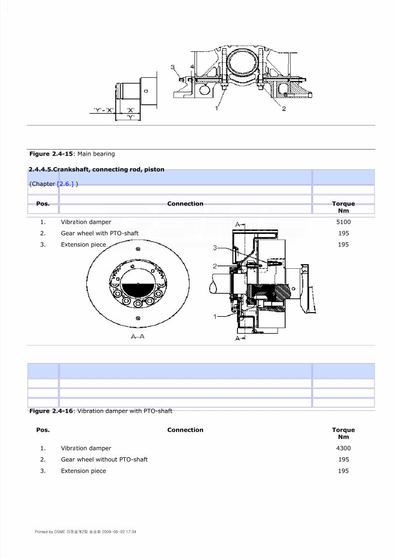
8/9/2019 W26 Instruction Manual
http://slidepdf.com/reader/full/w26-instruction-manual 188/304
P_0000045
Figure 2.4-15: Main bearing
2.4.4.5.Crankshaft, connecting rod, piston
(Chapter [2.6.] )
Figure 2.4-16: Vibration damper with PTO-shaft
Pos. Connection TorqueNm
1. Vibration damper 5100
2. Gear wheel with PTO-shaft 195
3. Extension piece 195
Pos. Connection TorqueNm
1. Vibration damper 4300
2. Gear wheel without PTO-shaft 195
3. Extension piece 195
Printed by DSME 의장설계2팀 송승화 2009-06-02 17:34

8/9/2019 W26 Instruction Manual
http://slidepdf.com/reader/full/w26-instruction-manual 189/304
P_0000045
Figure 2.4-17: Vibration damper without PTO-shaft
Figure 2.4-18: Crankshaft gear
Pos. Connection TorqueNm
1. Split gear wheel on crankshaft 270
2. Split gear wheel on crankshaft 540
Pos. Connection TorqueNm
1. Flywheel 4300
2. Toothed ring 80
Printed by DSME 의장설계2팀 송승화 2009-06-02 17:34

8/9/2019 W26 Instruction Manual
http://slidepdf.com/reader/full/w26-instruction-manual 190/304
P_0000045
Figure 2.4-19: Flywheel
Figure 2.4-20: Big end bearing
2.4.4.6.Cylinder head with valves
(Chapter [2.7.] )
Pos. Connection Torque /Jack
pressure
Elongation studmm
1. Big end stud, mounting 100 Nm .
2. Big end bearing cap, tightening
first stepsecond stepthird stepElongation
tool nr.[9612ZT944]
500 bar970 bar970 bar
Measure size 'X'Measure size 'Y'
'Y'-'X'= 0.6-0.8
Pos. Connection Torque
Printed by DSME 의장설계2팀 송승화 2009-06-02 17:34

8/9/2019 W26 Instruction Manual
http://slidepdf.com/reader/full/w26-instruction-manual 191/304
P_0000045
Figure 2.4-21: Multiduct connection
Figure 2.4-22: Tappet casing
Nm
1. Multiduct to cylinder head 195
2. Multiduct to exhaust gas manifold 195
3. Multiduct to engine block: 80
Pos. Connection TorqueNm
1. Tappet casing 46
Pos. Connection Torque /Jack
pressure
Stud elongationmm
1. Cylinder head stud, mounting 300 Nm .
1. Cylinder head, tightening
first stepsecond stepthird stepElongation
tool nr.
[9612ZT904]
300 bar620 bar620 bar
Measure size 'X'Measure size 'Y'
'Y'-'X' = 0.78 - 0.95
Printed by DSME 의장설계2팀 송승화 2009-06-02 17:34

8/9/2019 W26 Instruction Manual
http://slidepdf.com/reader/full/w26-instruction-manual 192/304
P_0000045
Figure 2.4-23: Cylinder head
Figure 2.4-24: Rocker arm mechanism
2.4.4.7.Camshaft and valve drive
(Chapter [2.8.] )
Pos. Connection TorqueNm
1. Rocker arm bracket 390
2. Locking nut 120
3. Locking nut 220
Pos. Connection TorqueNm
1. Intermediate gear wheel shaft cover 46
2. Gear wheel 560
Printed by DSME 의장설계2팀 송승화 2009-06-02 17:34

8/9/2019 W26 Instruction Manual
http://slidepdf.com/reader/full/w26-instruction-manual 193/304
P_0000045
Figure 2.4-25: Intermediate gear shaft
Figure 2.4-26: Camshaft / camshaft gearwheel
Note!
Pos. Connection TorqueNm
1. Camshaft section to journal:first step
second step (final setting)
40
135
2. Thrust ring to journal 80
3. Journal to camshaft gear wheel 195
Pos. Connection TorqueNm
1. Drive shaft nut 100
2. Locking bolt 10
Printed by DSME 의장설계2팀 송승화 2009-06-02 17:34

8/9/2019 W26 Instruction Manual
http://slidepdf.com/reader/full/w26-instruction-manual 194/304
P_0000045
Make adjustments only with required tools.
Figure 2.4-27: Actuator drive
2.4.4.8.Injection system components
(Chapter [2.9.] )
Figure 2.4-28: Fuel injector
Pos. Connection TorqueNm
1. Fuel injector nut 45
2. Stud 10
Pos. Connection TorqueNm
1. Connecting pipe 120
2. HP fuel line union 140
Printed by DSME 의장설계2팀 송승화 2009-06-02 17:34

8/9/2019 W26 Instruction Manual
http://slidepdf.com/reader/full/w26-instruction-manual 195/304
P_0000045
Figure 2.4-29: Fuel injector, HP fuel line
Figure 2.4-30: Fuel injector
3. Lock nut 60
Pos. Connection TorqueNm
1. Nozzle (Use loctite Molykote G-rapid plus or Never-Seez Regular grade NS 42 B onthread)
750..800
2. Pressure adjustement screw 50..70
3. Guiding screw 10..14
4. Plug 10..22
Printed by DSME 의장설계2팀 송승화 2009-06-02 17:34

8/9/2019 W26 Instruction Manual
http://slidepdf.com/reader/full/w26-instruction-manual 196/304
P_0000045
Figure 2.4-31: HP fuel pump drive and tappet housing
2.4.4.9.General table of tightening torques for not specified bolt connections
When the tightening torque is not specified, use the values from the table below.
Unless stated otherwise all threads and contact surfaces of the nuts and bolts should be sparingly lubricated with
engine oil before tightening.
For general information, see also:
- DIN 13
- "VDI Richtliniën 2230"
- DIN - 912 - 931 - 933 - 6912 - 7984.
Pos. Connection TorqueNm
1. HP fuel pump 140
2. Fuel pump support 46
3. Barrel 90
4. Cover for barrel 53
Printed by DSME 의장설계2팀 송승화 2009-06-02 17:34

8/9/2019 W26 Instruction Manual
http://slidepdf.com/reader/full/w26-instruction-manual 197/304

8/9/2019 W26 Instruction Manual
http://slidepdf.com/reader/full/w26-instruction-manual 198/304
P_0000045
2.4.5.1.Adjustments
2.4.5.2.Tolerances
Note!
For determination of wear, engine components and measuring equipment should for some hours first be acclimated at
room temperature ( 20 °C).
Timing, clearances and settings
Valve clearances cold engine:- Inlet valve: ................................................... 0.75 mm- Exhaust valve: ............................................. 0.75 mm
Fuel delivery commencement: ....................... See test recordsOpening pressure fuel injector needle: ......... 450 bar
Nominal speed
900 rpm
Overspeed stop
1035 ± 10 rpm
. Part, measuring point
. Bearings
. The engine bearings consist of a steel shell onto which a very tiny bonding of almost pure Aluminium.On this bonding is a running layer of Aluminium alloy.It concerns bearings for:
- crankshaft- connecting rod big end- camshaft
A bearing is suitable for use as long as:- the shell thickness is expected to stay within the given tolerances, until the next inspection, (see thischapter).- the inside diameter is within the given tolerances, until the next inspection, (see this chapter).- the bearing shell is free of damage.- the bearing shell is free of corrosion.- the wear pattern is equal.- the running layer is not overloaded. An overloaded bearing shell can be recognized by locally meltedor smeared lining.
Restriction for refitting of bearings.Refitting is only allowed one time if the number of running hours is not more than 5000 hrs. even if thebearing is within the mentioned criteria.
New bearings are treated with a corrosion protection that has to be removed before mounting.
Where bearings show heavy wear grooves in the running layer, the quality of the lubricating oilcleaning process should be observed more carefully.
Part, measuring point Designmeasurements
Nominalclearance [mm]
No - Go
[mm]
Part, measuring point Max.[mm]
Min.[mm]
Nominalclearance [mm]
No - Go
[mm]
Lubricating oil pump (chapter [1.2.] )
Backlash driving gear wheel (1)lubricating oil pump gear wheel (2)
. . 0.45-0.75
0.85
Cooling water pump (chapter [1.4.] )
Backlash driving gear wheel (1)H.T. cooling water pump gear wheel (3)
. . 0.50-0.80
0.90
Backlash driving gear wheel (1)L.T. cooling water pump gear wheel (4)
. . 0.42-0.75
0.85
Printed by DSME 의장설계2팀 송승화 2009-06-02 17:34

8/9/2019 W26 Instruction Manual
http://slidepdf.com/reader/full/w26-instruction-manual 199/304

8/9/2019 W26 Instruction Manual
http://slidepdf.com/reader/full/w26-instruction-manual 200/304
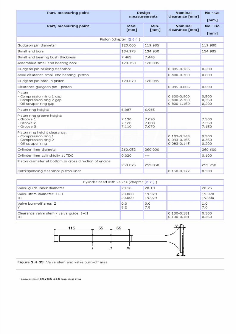
8/9/2019 W26 Instruction Manual
http://slidepdf.com/reader/full/w26-instruction-manual 201/304

8/9/2019 W26 Instruction Manual
http://slidepdf.com/reader/full/w26-instruction-manual 202/304
P_0000045
Figure 2.4-34: Inlet valve and valve seat in cylinder head
Figure 2.4-35: Exhaust valve and valve seat in cylinder head
Part, measuring point Design
measurements
Nominal
clearance [mm]
No - Go
[mm]
Part, measuring point Max.[mm]
Min.[mm]
Nominalclearance [mm]
No - Go
[mm]
Driving gear (chapter [2.8.] )
Backlash crankshaft gear wheel (1)intermediate gear wheel (large) (2)
. . 0.05-0.40
0.50
Backlash intermediate gear wheel (3)camshaft gear wheel (4)
. . 0.05-0.30
0.40
Backlash gear wheel actuator drive (5)gear wheel actuator drive unit (6) . . 0.30-0.40 0.50
Backlash toothed ring flywheel (8)pinion starting unit (7)
. . 0.60-1.10
.
Backlash toothed ring flywheel (8)turning gear gear wheel (9)
. . 0.60-1.30
.
Axial clearance intermediate gear wheel . . 0.30-1.50 1.60
Printed by DSME 의장설계2팀 송승화 2009-06-02 17:34

8/9/2019 W26 Instruction Manual
http://slidepdf.com/reader/full/w26-instruction-manual 203/304

8/9/2019 W26 Instruction Manual
http://slidepdf.com/reader/full/w26-instruction-manual 204/304
P_0000045
Figure 2.4-37: Valve drive mechanism
* Shaft clearance in direction "e" is zero.
Figure 2.4-38: Actuator drive
Part, measuring point Designmeasurements
Nominalclearance [mm]
No - Go
[mm]
Part, measuring point Max.[mm]
Min.[mm]
Nominalclearance [mm]
No - Go
[mm]
Actuator (chapter [2.8.] )
Backlash driving gear * . . 0.12-0.18 0.25
Part, measuring point Designmeasurements
Nominalclearance [mm]
No - Go
[mm]
Part, measuring point Max.[mm]
Min.[mm]
Nominalclearance [mm]
No - Go
[mm]
Injection system (chapter [2.9.] )
Nozzle needle lift 'A' 0.6 0.5 . 0.8
Distance 'B' fuel pump push rod 1.1 0.9 . 1.2
Printed by DSME 의장설계2팀 송승화 2009-06-02 17:34

8/9/2019 W26 Instruction Manual
http://slidepdf.com/reader/full/w26-instruction-manual 205/304
P_0000045
Figure 2.4-39: Nozzle
Figure 2.4-40: fuel pump adjustment
2.4.6.Dimensions and masses
Printed by DSME 의장설계2팀 송승화 2009-06-02 17:34

8/9/2019 W26 Instruction Manual
http://slidepdf.com/reader/full/w26-instruction-manual 206/304
P_0000045
Figure 2.4-41: Engine components
1) 2) 3) Lubricating oil cooler insert with standard1 / higher2 / highest3 capacity
Dimensions and masses of cooler inserts; lubricating oil and charge air
Engine Dimensions [mm] Masses cooler inserts [kg]
Engine A B (B) C (C) D E G H J oil1 oil2 oil3 chargeair
6L268L269L26
121311851185
1001 (774)1007 (830)1007 (830)
756 (756)830 (906)830 (906)
970955955
490535535
55510101010
ø330ø330ø330
975975975
75 85 -75 85 12084 120 -
470570570
12V2616V2618V26
118511851185
830830830
978 (1007)978 (1007)978 (1007)
625625625
605605605
190019001900
ø370ø370ø370
130013001300
145 - -145 165 -145 165 -
680725725
Printed by DSME 의장설계2팀 송승화 2009-06-02 17:34

8/9/2019 W26 Instruction Manual
http://slidepdf.com/reader/full/w26-instruction-manual 207/304
P_0000045
Figure 2.4-42: Main parts
Printed by DSME 의장설계2팀 송승화 2009-06-02 17:34

8/9/2019 W26 Instruction Manual
http://slidepdf.com/reader/full/w26-instruction-manual 208/304
P_0000045
2.5.1.Engine block
The engine block is a one piece stiff nodular cast iron component. The engine block carries the underslung crankshaft.
The nodular cast iron main bearing caps (1) are tightened by two vertically main bearing cap studs (2) and two
horizontally side studs (3). Together they provide a very rigid crankshaft bearing construction. These studs are
tightened by hydraulic tools.
The camshaft bearing housings (4) are incorporated in the engine block.
The lubricating oil sump is mounted under the engine block and sealed by a rubber string gasket. A number of
crankcase covers are equipped with explosion relief valves.
Figure 2.5-1: Engine block
Note!
For maintenance background information, safety aspects, intervals, tolerances, and hydraulic tightening procedures,
see chapter [2.4.]
2.5.2.Main bearings
Main bearing shells are axially guided by lugs to obtain a correct position during assembly. The crankshaft axial
locating bearing, number '0', differs from the other bearings and is provided with thrust rings to limit the axial
displacement of the crankshaft.
Bearing shells are of a bi-metal type. All main bearing caps are provided with a temperature sensor. If abnormal
temperatures appear the suspected bearing, crankshaft deflections and the alignment have to be checked.
Note!
2.5.Engine Block with Bearings 2.5-PAAE062665-00
Printed by DSME 의장설계2팀 송승화 2009-06-02 17:34
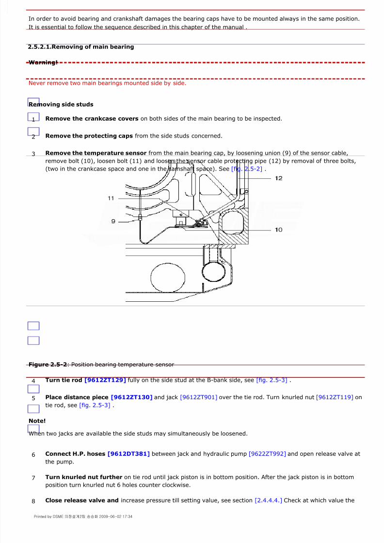
8/9/2019 W26 Instruction Manual
http://slidepdf.com/reader/full/w26-instruction-manual 209/304
P_0000045
In order to avoid bearing and crankshaft damages the bearing caps have to be mounted always in the same position.
It is essential to follow the sequence described in this chapter of the manual .
2.5.2.1.Removing of main bearing
Warning!
Never remove two main bearings mounted side by side.
Removing side studs
Figure 2.5-2: Position bearing temperature sensor
Note!
When two jacks are available the side studs may simultaneously be loosened.
1 Remove the crankcase covers on both sides of the main bearing to be inspected.
2 Remove the protecting caps from the side studs concerned.
3 Remove the temperature sensor from the main bearing cap, by loosening union (9) of the sensor cable,
remove bolt (10), loosen bolt (11) and loosen the sensor cable protecting pipe (12) by removal of three bolts,
(two in the crankcase space and one in the camshaft space). See [fig. 2.5-2] .
4 Turn tie rod [9612ZT129] fully on the side stud at the B-bank side, see [fig. 2.5-3] .
5 Place distance piece [9612ZT130] and jack [9612ZT901] over the tie rod. Turn knurled nut [9612ZT119] on
tie rod, see [fig. 2.5-3] .
6 Connect H.P. hoses [9612DT381] between jack and hydraulic pump [9622ZT992] and open release valve at
the pump.
7 Turn knurled nut further on tie rod until jack piston is in bottom position. After the jack piston is in bottom
position turn knurled nut 6 holes counter clockwise.
8 Close release valve and increase pressure till setting value, see section [2.4.4.4.] Check at which value the
Printed by DSME 의장설계2팀 송승화 2009-06-02 17:34

8/9/2019 W26 Instruction Manual
http://slidepdf.com/reader/full/w26-instruction-manual 210/304
P_0000045
Figure 2.5-3: Positioning jack on side stud
Removing main bearing cap nuts
nut comes free. In case jack pressure deviates more than 5% of setting value the connection should be
investigated.
9 Loosen with tool pin [9612ZT125] the side stud nut 5..6 holes.
10 Slowly lower pressure till zero and give time to the jack piston to travel to the bottom position.
11 Disconnect hose, remove hydraulic tools.
12 Remove side stud.
13 Repeat this procedure on the side stud at the A-bank side.
14 First place from tool set [9612ZT906] the two girders [9612ZT261] with roller bearings on the sliding bars in
the crankcase, see [fig. 2.5-4] .
15 Place in recesses of the girders lifting tool [9612ZT267] together with support [9612ZT263] . Take care the
lifting device fits well in both girders.
16 Place the top plate for the hydraulic jacks [9612ZT262] in support [9612ZT263] .
17 Place from tool set [9612ZT903] , simultaneously both hydraulic jacks [9612ZT901] , both distance pieces
[9612ZT128] and both tie-rods [9612ZT127] in the recesses of top plate [9612ZT262] . To facilitate the insert
of the jacks, the lifting tool can be raised and lowered with spindle (14) using a spanner or air tool
.
Printed by DSME 의장설계2팀 송승화 2009-06-02 17:34

8/9/2019 W26 Instruction Manual
http://slidepdf.com/reader/full/w26-instruction-manual 211/304
P_0000045
Figure 2.5-4: Lifting tool for main bearing cap
18 If necessary, bar the crankshaft for good accessibility.
19 Slide the trolley with the hydraulic jacks underneath the main bearing cap.
20 Raise the lifting tool by means of the spindle (14) till the tie rods just touch the main bearing cap studs.
21 Turn the tie rods fully on the studs.
22 Raise the lifting tool further till the distance pieces are just touching the bearing cap.
23 Turn the knurled nuts [9612ZT119] on the tie rods and tighten with tool pin [9612ZT125] .
24 Connect H.P. hoses [9612DT381] between hydraulic pump [9622ZT992] and jacks, open release valve at
pump and turn knurled nuts further on until jack pistons are in bottom position.
25 After jack pistons are in bottom position turn knurled nuts 6 holes counter clockwise.
26 Pressurise jacks till setting value. See section
27 Turn bearing cap nuts 5..6 holes loose.
28 Slowly lower pressure till zero, wait a few seconds to allow the jack pistons to travel to the bottom position
and disconnect the H.P. hoses.
29 Remove both knurled nuts and turn the tie rods from the main bearing cap studs and lower lifting tool
together with the hydraulic tools.
30 Remove simultaneously both distance pieces, tie rods and
hydraulic jacks.
Printed by DSME 의장설계2팀 송승화 2009-06-02 17:34

8/9/2019 W26 Instruction Manual
http://slidepdf.com/reader/full/w26-instruction-manual 212/304
P_0000045
Figure 2.5-5: Lifting tool for main bearing cap
Lowering main bearing cap
Note!
If it is not possible to lower the main bearing cap loosen the side studs of the adjacent main bearing caps.
Removing of bearing shells
Bar crankshaft to make lube oil supply hole in journal fully visible.
Insert bearing shell driver [9612ZT910] into the lube oil supply hole.
Carefully bar crankshaft till driver starts pushing the bearing shell. Take care the protruding part of the driver easily
slides in the oil groove of the bearing housing.
After most of the bearing shell is pushed out the remaining part can be slide out manually.
Figure 2.5-6: Bearing shell driver
2.5.2.2.Inspection of main bearings and journals
31 Remove top plate [9612ZT262] from support [9612ZT263] , see [fig. 2.5-5] .
32 Elevate lifting tool against main bearing cap and lift bearing cap a little. Hold cap in position.
33 Remove main bearing cap nuts.
34 Lower main bearing cap.
35 Remove the lower bearing shell with main bearing cap in lowest position.
36 In some cases the upper bearing shell can manually be pushed out.
If the bearing shell can't be pushed out manually, make use of the bearing shell driver [9612ZT910] , see
[fig. 2.5-6] :
1 Clean bearing shells and check for wear, scoring and other damages.
2 Main bearing journals should be inspected for surface finish. Damaged journals, i.e. rough surface,
scratches, marks, indents etc. should be polished.
Printed by DSME 의장설계2팀 송승화 2009-06-02 17:34

8/9/2019 W26 Instruction Manual
http://slidepdf.com/reader/full/w26-instruction-manual 213/304
P_0000045
Note!
No scraping of bearing shells, caps and housings is permitted.
2.5.2.3.Main bearing assembling
Bearing shell mounting
Figure 2.5-7: Inserting main bearing shell
Insert driver [9612ZT910] into the lube oil supply hole, see [fig. 2.5-8] .
Bar crankshaft carefully until bearing shell is pushed into position. Take care not to damage the bearing shell lugduring turning in.
Remove driver.
Figure 2.5-8: Driving main bearing shell into position
Lifting bearing cap
1 Clean both main bearing shells, cap and journal very carefully.
New bearing shells have to be degreased before mounting.
2 Oil upper bearing shell only at running side. Avoid any oil at the back side of the shell and at the bearing cap
3 Place end of bearing shell in slot of the housing with part number facing to the driving end of the engine and
with lug guiding in oil groove. Push bearing shell manually as far as possible. Usually it is possible to mount
bearing shell manually in position. Support shell sufficiently by hand, see [fig. 2.5-7] .
4 If it is not possible to insert the complete bearing shell manually into position:
5 Place lower bearing shell in main bearing cap with part number facing to the driving end of the engine. Takecare main bearing cap and outer side of main bearing shell are clean, dry and free from damages and indents.
6 Lubricate the bearing cap side abutting faces.
7 Use from tool set [9612ZT906] lifting tool [9612ZT267] and support [9612ZT263] to elevate main bearing cap
against cylinder block, see [fig. 2.5-4] .
Printed by DSME 의장설계2팀 송승화 2009-06-02 17:34

8/9/2019 W26 Instruction Manual
http://slidepdf.com/reader/full/w26-instruction-manual 214/304
P_0000045
Mounting side studs
Note!
Side studs are different in length depending on the position of the engine feet. Consequently a difference inelongation and so in nut shifting exists. Consult section [2.4.4.]
Figure 2.5-9: Apply new O-ring with silicon grease
Note!
Side studs may not touch main bearing cap studs.
Side stud at A-bank side
Turn tie rod of tool [9612ZT902] fully on side stud at the A-bank side only, see [fig. 2.5-3] .
Place distance piece and jack [9612ZT901] over tie rod and turn on the knurled nut. Connect H.P. hose between jack and pump, open release valve at pump and tighten the knurled nut to displace jack piston into bottom position.
Pressurise jack till 100 bar and tighten side stud nut firmly with tool pin.
Check with feeler of 0.05 mm for any clearance between nut and cylinder block or engine foot. Clearance should notexist.
Slowly lower pressure till zero. Take care jack piston travels to bottom position.
Remove jack from side stud.
Place measuring device [9612ZT941] over stud and measure length from nut surface till end of stud is length 'X'
and record this length. See [fig. 2.5-10] .
Side stud at B-bank side
Repeat point 14 for side stud at the B-bank side.
8 With main bearing cap in top position turn on bearing cap nuts. Tighten nuts firmly with tool pin
.
9 Lower the lifting tool.
10 Clean both bearing cap side studs (17) and fit them with new O-rings (16). Provide O-rings with silicon
grease, see [fig. 2.5-9] .
11 After the side studs are fully turned in, turn the studs half a turn counter clockwise to avoid contact with the
main bearing cap studs. Mark position of the side studs with felt marker and avoid turning of the studs during
mounting the nuts.
12 Oil the stud thread lightly.
13 Fit nuts on side studs and tighten them with the tool pin.
14 1st step
15 1st step
Printed by DSME 의장설계2팀 송승화 2009-06-02 17:34

8/9/2019 W26 Instruction Manual
http://slidepdf.com/reader/full/w26-instruction-manual 215/304
P_0000045
Main bearing cap studs
Increase pressure till 200 bar.
Firmly tighten bearing cap nuts with tool pin.
Check with feeler blade of 0.05 mm that no clearance exists between nut and bearing cap.
Slowly lower pressure till zero. Take care jack pistons travels till bottom position.
Disconnect hoses from jacks and remove both jacks from main bearing cap studs using tool [9612ZT906] , see[fig. 2.5-4] .
Place measuring device [9612ZT941] over stud and measure length from nut surface till end of stud is length 'X'
and record this length.See [fig. 2.5-10] .
Fit jacks again on both studs and connect hoses to hydraulic pump.
Increase pressure till setting value, see section [2.4.4.4.]
Firmly tighten bearing cap nuts with tool pin. Slowly lower pressure till zero. Take care jack pistons travel till bottom position.
Increase pressure till setting value and turn bearing cap nuts with tool pin further on. This should be possible over afew degrees only.
Check with a feeler blade of 0.05 mm that no clearance exists between bearing cap and nut.
Slowly lower pressure till zero. Take care jack pistons travel till bottom position.
Disconnect hoses and remove main bearing tools out of crankcase, see [fig. 2.5-4] .
Place measuring device [9612ZT941] over stud and measure the length from nut surface till end of stud is length 'Y'and record this length. Measure and record also the length of the second stud.
The calculated elongation 'Y' - 'X' of the studs has to be within the limits given in section [2.4.4.4.]
Figure 2.5-10: Measuring stud elongation
Warning!
In case the stud elongation is outside limits the connection is NOT safe. In such a case all components have to be
disconnected and examined on deviation in material or wrong assembling.
Side stud at A-bank side
Turn tie rod of tool [9612ZT902] fully on side stud at the A-bank side only, see [fig. 2.5-3] .
Place distance piece and jack [9612ZT901] over the tie rod and tighten the knurled nut.Connect H.P. hose between jack and pump, open release valve at pump and tighten knurled nut to displace jackpiston into bottom position.
Pressurise jack till setting value and tighten side stud nut firmly with tool pin.
Slowly lower pressure till zero. Take care jack piston travels to bottom position.
16 Fit both main bearing cap jacks according section [2.5.2.1.] point 14 up to and including 24. After jack
pistons are in bottom position tighten knurled nuts with tool pin [9612ZT125] .
17 1st step
18 2nd step
19 3rd step
20 2nd step
Printed by DSME 의장설계2팀 송승화 2009-06-02 17:34
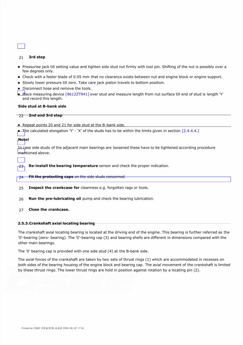
8/9/2019 W26 Instruction Manual
http://slidepdf.com/reader/full/w26-instruction-manual 216/304
P_0000045
Pressurise jack till setting value and tighten side stud nut firmly with tool pin. Shifting of the nut is possibly over afew degrees only.
Check with a feeler blade of 0.05 mm that no clearance exists between nut and engine block or engine support.
Slowly lower pressure till zero. Take care jack piston travels to bottom position.
Disconnect hose and remove the tools.
Place measuring device [9612ZT941] over stud and measure length from nut surface till end of stud is length 'Y'and record this length.
Side stud at B-bank side
Repeat points 20 and 21 for side stud at the B-bank side.
The calculated elongation 'Y' - 'X' of the studs has to be within the limits given in section [2.4.4.4.]
Note!
In case side studs of the adjacent main bearings are loosened these have to be tightened according procedure
mentioned above.
2.5.3.Crankshaft axial locating bearing
The crankshaft axial locating bearing is located at the driving end of the engine. This bearing is further referred as the'0'-bearing (zero- bearing). The '0'-bearing cap (3) and bearing shells are different in dimensions compared with the
other main bearings.
The '0' bearing cap is provided with one side stud (4) at the B-bank side.
The axial forces of the crankshaft are taken by two sets of thrust rings (1) which are accommodated in recesses on
both sides of the bearing housing of the engine block and bearing cap. The axial movement of the crankshaft is limited
by these thrust rings. The lower thrust rings are hold in position against rotation by a locating pin (2).
21 3rd step
22 2nd and 3rd step
23 Re-install the bearing temperature sensor and check the proper indication.
24 Fit the protecting caps on the side studs concerned.
25 Inspect the crankcase for cleanness e.g. forgotten rags or tools.
26 Run the pre-lubricating oil pump and check the bearing lubrication.
27 Close the crankcase.
Printed by DSME 의장설계2팀 송승화 2009-06-02 17:34

8/9/2019 W26 Instruction Manual
http://slidepdf.com/reader/full/w26-instruction-manual 217/304
P_0000045
Figure 2.5-11: Crankshaft axial locating bearing
Note!
For maintenance background information, safety aspects, intervals, tolerances, inspections, and hydraulic tightening
procedures, see chapter [2.4.]
2.5.3.1.Removing of the '0'-bearing
Warning!
Never remove main bearing number 1 if the '0'-bearing is removed. Never move the crankshaft in axial direction by
exerting a force on the counter weights
Before removal of the '0'-bearing, first measure the axial clearance of the crankshaft. To be able to measure this
clearance it is necessary to move the crankshaft to and fro in axial direction.
Measuring the axial clearance
Removing the '0'-bearing
1 Pre-lubricate the engine for a few minutes.
2 Move the crankshaft to and fro in axial direction with tool [9612ZT376] , see section
3 Move the crankshaft as far as possible to the driving end side.
4 Place a dial gauge between engine block and flywheel and adjust it to zero.
5 Move the crankshaft as far as possible to the free end side.
6 Note the value found, and verify the clearance with the commissioning report, see also section [2.4.5.2.] forthe nominal clearance.
7 Follow procedure "Removing of main bearing" section [2.5.2.1.] point 1 up to and included 34 , except point
13.
Printed by DSME 의장설계2팀 송승화 2009-06-02 17:34

8/9/2019 W26 Instruction Manual
http://slidepdf.com/reader/full/w26-instruction-manual 218/304

8/9/2019 W26 Instruction Manual
http://slidepdf.com/reader/full/w26-instruction-manual 219/304
P_0000045
case, the groove in between serves for oil supply to the turbocharger, and the bearing has no axial function.
Figure 2.5-12: Camshaft assembly with bearing bushes
2.5.4.1.Inspection of camshaft bearing bush
2.5.4.2.Removing camshaft bearing bushes and axial bearing bushes
1 Remove the camshaft section and journal, see chapter
2 After the camshaft journal is removed, the running surface of the bearing bush can be inspected. Clean thebearing bush and check visually for wear, scoring or damages and measure the diameter. If the inspected
bearing is worn other bearings could also be worn and have to be inspected as well.
1 Remove the camshaft cover, HP fuel pumps, fuel pump brackets, tappets for inlet and exhaust, camshaft
sections and journals from the cylinder unit concerned and the adjacent cylinder units . In case of axial
camshaft bearing bushes the gearwheel with shaft has to be removed, see chapter concerned.
2 Place extracting tool into position according to [fig. 2.5-13] for removing of camshaft bearing bush (3).
Mind the position of disc [9612ZT546] . The drawing left shows bearing removed and drawing right shows the
bearing not removed.
Printed by DSME 의장설계2팀 송승화 2009-06-02 17:34
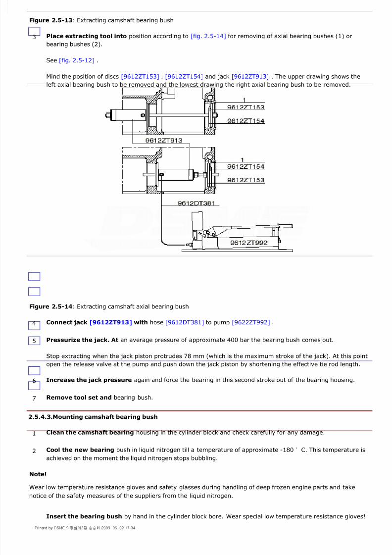
8/9/2019 W26 Instruction Manual
http://slidepdf.com/reader/full/w26-instruction-manual 220/304
P_0000045
Figure 2.5-13: Extracting camshaft bearing bush
Figure 2.5-14: Extracting camshaft axial bearing bush
2.5.4.3.Mounting camshaft bearing bush
Note!
Wear low temperature resistance gloves and safety glasses during handling of deep frozen engine parts and take
notice of the safety measures of the suppliers from the liquid nitrogen.
3 Place extracting tool into position according to [fig. 2.5-14] for removing of axial bearing bushes (1) or
bearing bushes (2).
See [fig. 2.5-12] .
Mind the position of discs [9612ZT153] , [9612ZT154] and jack [9612ZT913] . The upper drawing shows the
left axial bearing bush to be removed and the lowest drawing the right axial bearing bush to be removed.
4 Connect jack [9612ZT913] with hose [9612DT381] to pump [9622ZT992] .
5 Pressurize the jack. At an average pressure of approximate 400 bar the bearing bush comes out.
Stop extracting when the jack piston protrudes 78 mm (which is the maximum stroke of the jack). At this point
open the release valve at the pump and push down the jack piston by shortening the effective tie rod length.
6 Increase the jack pressure again and force the bearing in this second stroke out of the bearing housing.
7 Remove tool set and bearing bush.
1 Clean the camshaft bearing housing in the cylinder block and check carefully for any damage.
2 Cool the new bearing bush in liquid nitrogen till a temperature of approximate -180 °C. This temperature is
achieved on the moment the liquid nitrogen stops bubbling.
Insert the bearing bush by hand in the cylinder block bore. Wear special low temperature resistance gloves!
Printed by DSME 의장설계2팀 송승화 2009-06-02 17:34

8/9/2019 W26 Instruction Manual
http://slidepdf.com/reader/full/w26-instruction-manual 221/304
P_0000045
2.5.4.4.Mounting camshaft axial bearing bush
The shrinking process of the axial bearing bushes and the camshaft bearing bushes is similar.
Note!
Wear low temperature resistance gloves and safety glasses during handling of deep frozen engine parts and take
notice of the safety measures of the suppliers from the liquid nitrogen.
Figure 2.5-15: Holding bearing bushes during mounting
3
4 The lube oil hole in the bearing bush has to come in line with the lube oil hole in the cylinder block. To position
bearing bush in cylinder block housing use tool pin [9612ZT194] .
5 Wait till the temperature of the bearing is the same as the engine block. Check if inner diameter of the
assembled bearing is according the measurements given in section [2.4.5.2.]
6 Mount the camshaft journal and camshaft sections, tappets, push rods, fuel pump bracket and fuel pumps.
See chapters concerned.
7 Adjust valve clearances. See chapter [2.7.] 2.
8 Check the lubrication and close the camshaft covers.
1 Remove camshaft gearwheel, see section
2 Remove camshaft section and journal next to the gearwheel assembly , see section
3 Clean the camshaft bearing housing in the cylinder block. Check camshaft bore in engine block on possible
damages, indents or rough surface.
4 Check diameter of camshaft bore and compare diameter with dimensions in section
5 Check the lubricating oil channel is clean.
6 Cool the bearing bushes in liquid nitrogen. The bearing bushes are at temperature when bubbling of the
nitrogen is stopped.
Place both bearing bushes into the camshaft bore and fit tool [9612ZT948] quickly to keep them tight together.
7 Remove tool [9612ZT948] after 5 minutes to be sure the bearing bushes are tight.
8 Check with a dial gauge, resting against the side of the engine block, the parallelling of the axial running face
of the outer bearing bush with the engine block at four different positions.
9 Check with a micrometer at four different positions the parallelling of the axial running faces between outer
Printed by DSME 의장설계2팀 송승화 2009-06-02 17:34

8/9/2019 W26 Instruction Manual
http://slidepdf.com/reader/full/w26-instruction-manual 222/304
P_0000045
2.5.5.Replacing cylinder head studs
Figure 2.5-16: Replacing cylinder head stud
2.5.6.Crankcase safety valves
Crankcase explosions result from ignition of a combustible mixture of lubricating oil or gas and air. Combustion
pressure, which develops following ignition within the confined space, frequently exceeds the strength of the
crankcase housing or covers, causing destructive failure. The ignition source may be gas blow-by or an overheated
engine part.
Any part moving relative to another potentially can become excessively hot through friction to initiate combustion ifnot lubricated or cooled properly. All bearings, bushing, thrust surfaces, pistons, etc. as well as the surfaces these
parts touch, are included. Broken piston or rings that allow fire in the combustion chamber to blow through to the
crankcase is also a source of crankcase ignition.
Operators must recognize that all engine/compressors have the potential to develop hot spots capable of igniting
crankcase vapours and producing a crankcase explosion. The potential can be reduced or safely contained by attention
and inner bearing bush.
10 Mount camshaft section, journal, gearwheel assembly and end journal.
11 Check if the axial clearance is within the tolerance mentioned in section
1 Fit tool [9612ZT935] onto the stud and tighten the bolt on top of it. Loosen the stud by using a spanner onthe bolt, (the bolt is provided with left-handed thread).
2 Clean thread and recess in top of the engine block and check for corrosion.
3 Degrease both thread ends of the new stud and check the thread ends are free of damage by turning on and
off a cylinder head nut and by turning in and out the stud into the engine block threaded hole.
4 Immerse the thread of the lower part of the stud in Tectyl and turn the stud into the threaded hole in the
engine block. For Tectyl part number see parts catalogue.
5 Tighten stud by torque spanner, see section
6 Before applying sealing compound (1) in gap between engine block and stud make sure that the sealing
compound surfaces are free from Tectyl.
7 Apply sealing compound (1) in gap between engine block and stud to avoid liquids penetrating. For sealing
compound see parts catalogue.
Printed by DSME 의장설계2팀 송승화 2009-06-02 17:34

8/9/2019 W26 Instruction Manual
http://slidepdf.com/reader/full/w26-instruction-manual 223/304
P_0000045
to good maintenance practices.
Engine stop / cool down period
If a crankcase explosion occurs, allow the equipment to cool down at least 15 minutes before attempting to open any
crankcase cover doors. The heat inside the crankcase will promote an inrush of fresh air when cover doors are
removed and hot spots remaining from the explosion may cause a violent secondary explosion.
If smoke is observed coming from crankcase vents ore breathers, safely shut down the equipment and vacate the
area.
Smoke from vents or breathers (especially white smoke) is an indication that a hot spot is vaporizing lubricating oiland is often observed as a precursor to a crankcase explosion.
A sudden increase in crankcase pressure is an indication of gas blow-by probably caused by broken piston rings
indicates an increased risk of a crankcase explosion.
Working
A corrugated plate valve (1), see [fig. 2.5-17] , is by a conical shaped spring (2) forced on an O-ring seat (3) closing
the crankcase to the outside. In case of an excessive overpressure (explosion) the plate valve is forced into open
position allowing gasses to escape through a number of baffle plates (4). The baffle plates extinguish the flames. The
conical shape spring closes the plate valve and avoids the entering of fresh air.
Maintenance
1 Periodically open the plate valve manually over the full stroke and check plate valve returns to its seat
without hamper, see section [2.4.1.]
2 Check conical spring on spring force. Renew oxidised springs.
3 Periodically renew all O-rings, see chapter [2.4.] 1..
4 Check by feeler gauge if plate valve is resting on the O-ring and not on the steel O-ring housing.
5 After O-ring renewal move plate valve manually over the full stroke, see point 1.
Printed by DSME 의장설계2팀 송승화 2009-06-02 17:34

8/9/2019 W26 Instruction Manual
http://slidepdf.com/reader/full/w26-instruction-manual 224/304
P_0000045
Figure 2.5-17: Crankcase safety valve
Printed by DSME 의장설계2팀 송승화 2009-06-02 17:34

8/9/2019 W26 Instruction Manual
http://slidepdf.com/reader/full/w26-instruction-manual 225/304
P_0000045
2.6.1.Crankshaft
The crankshaft design features a very short cylinder distance with a maximum bearing length resulting in a short
engine. The crankshaft is forged from one piece of high tensile steel.
Counterweights are mounted hydraulically onto the crankshaft webs. The high degree of balancing results in an even
and thick oil film for all bearings. Main bearings and crankshaft bearings are of the bimetal type with a steel back and
a soft running layer with excellent corrosion resistance. The gear wheel on the crankshaft is mounted by a flange
connection.
The crankshaft is provided with a torsional vibration damper at the free end of the engine.
Note!
For maintenance background information, safety aspects, intervals, tolerances, inspections, and hydraulic tightening
procedures, see chapter [2.4.]
2.6.1.1.Crankshaft deflections
Take crankshaft deflection readings only when engine and foundation are at ambient temperature (cold engine) or atnormal operating temperature (hot engine), which means within 40 minutes after running the engine for more than 6
hours on at least 60% load.
All measurements have to be recorded on "Crankshaft alignment" measurement record supplied by Wärtsilä. The
document has to be filled in completely,
Note!
Before taking crankshaft deflections on an hot engine, the dial gauge should be warmed up to the same temperature
of the engine in order to avoid temperature influence on the readings. For instance the dial gauge could be warmed
up by placing it on the engine feet for a while (15 minutes).
Figure 2.6-1: Taking crankshaft deflection readings
2.6.Crankshaft, Connecting Rod, Piston and Liner 2.6-PAAE062665-00
1 Lubricate the bearings for a few minutes by running the pre-lubricating pump.
2 Remove crankcase covers at both sides.
3 Start at cylinder 1 and turn crankshaft clockwise till crankpin is ±30 ° after Bottom Dead Centre ( BDC ).
This crankshaft position is starting point 'A' for the dial gauge reading, see [fig. 2.6-1] .
4 Place a dial gauge in between the centre points of the counter weights at position 'A' and adjust dial gauge at
zero. Rotate dial gauge a few times between centre points and check reading is still at zero.
Printed by DSME 의장설계2팀 송승화 2009-06-02 17:35

8/9/2019 W26 Instruction Manual
http://slidepdf.com/reader/full/w26-instruction-manual 226/304
P_0000045
2.6.1.2.Measurement axial clearance thrust bearing
Figure 2.6-2: Measuring crankshaft axial clearance
Note!
Never apply any force on the counter weights to move the crankshaft.
2.6.2.Driving unit
Driving unit
The connecting rod, piston and cylinder liner form the driving unit. For maintenance the driving unit has to be lifted in
one assembly.
5 Turn crankshaft till dial gauge is in position 'B' and record dial gauge reading in measurement record.
6 Turn crankshaft till dial gauge is in position 'C' and record dial gauge reading in measurement record.
7 Turn crankshaft till dial gauge is in position 'D' and record dial gauge reading in measurement record.
8 Turn crankshaft till dial gauge is in position 'E' and record dial gauge reading in measurement record.
9 Repeat procedure for remaining cranks.
10 Compare crankweb deflections readings with readings of commissioning protocol or engine test bed report.
In case the readings are out of tolerance investigate reason and make corrections, see chapter [2.4.] If no
improvements can be obtained, consult the nearest Wärtsilä Service Office.
11 Replace crankcase covers.
1 Lubricate the bearings for a few minutes by running the pre-lubricating pump.
2 Apply the dial gauge for instance against the plane end surface of the flywheel.
3 Move the crankshaft by lever [9612ZT376] in either direction until contact is established with the thrust
bearing, see [fig. 2.6-2] .
4 Adjust the dial gauge to zero.
5 Move the crankshaft in the opposite direction and read the axial clearance on the dial gauge.
6 Compare readings with the readings of the commissioning protocol or engine test bed report. In case the
readings are out of tolerance, check the axial bearing rings and in case of new assembled axial bearing rings
check the mounting procedure.
Printed by DSME 의장설계2팀 송승화 2009-06-02 17:35

8/9/2019 W26 Instruction Manual
http://slidepdf.com/reader/full/w26-instruction-manual 227/304
P_0000045
For piston cooling, lubrication of piston skirt, gudgeon pin bearing and big end bearing, see chapter [1.2.]
Connecting rod
The big end has a horizontal split (1). The big end bearing consists of the lower bearing shell (2) and the upper
bearing shell (3).
The small end has a frozen in bearing (4), see [fig. 2.6-3] (drawing view according to stndard position of observer -
see chapter [0.0)] .
The connecting rod studs (5) are hydraulically tightened, for background information see section [2.4.3.]
Figure 2.6-3: Connecting rod
Piston
The piston consists of a nodular piston skirt (6) and a steel piston crown (7) bolted together by two bolts (8).
Note!
Do not remove the piston crown from the piston skirt.
Printed by DSME 의장설계2팀 송승화 2009-06-02 17:35

8/9/2019 W26 Instruction Manual
http://slidepdf.com/reader/full/w26-instruction-manual 228/304
P_0000045
Figure 2.6-4: Piston
Cylinder liner
The cylinder liner (9), at the top provided with an anti bore-polishing ring (10), is of a flanged type and symmetrically
supported on top of the cylinder block. See [fig. 2.6-5] .
The cylinder liner cooling is divided in two sections; a large volume in the lower section (11) for uniform cooling water
distribution and a smaller upper section (12) for efficient cooling by high water flow.
Note!
Always handle pistons and connecting rods with care.
Printed by DSME 의장설계2팀 송승화 2009-06-02 17:35
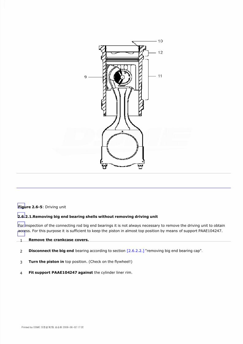
8/9/2019 W26 Instruction Manual
http://slidepdf.com/reader/full/w26-instruction-manual 229/304
P_0000045
Figure 2.6-5: Driving unit
2.6.2.1.Removing big end bearing shells without removing driving unit
For inspection of the connecting rod big end bearings it is not always necessary to remove the driving unit to obtain
access. For this purpose it is sufficient to keep the piston in almost top position by means of support PAAE104247.
1 Remove the crankcase covers.
2 Disconnect the big end bearing according to section [2.6.2.2.] "removing big end bearing cap".
3 Turn the piston in top position. (Check on the flywheel!)
4 Fit support PAAE104247 against the cylinder liner rim.
Printed by DSME 의장설계2팀 송승화 2009-06-02 17:35

8/9/2019 W26 Instruction Manual
http://slidepdf.com/reader/full/w26-instruction-manual 230/304
P_0000045
Figure 2.6-6: Piston support for big end bearing inspection
2.6.2.2.Removing driving unit
The connecting rod / piston assembly has to be removed always in conjunction with the cylinder liner. Before
commencing maintenance drain and collect cooling water for re-use.
5 Turn the crankshaft slowly out of the direction of the support, see arrow in [fig. 2.6-6] , until the piston is
resting on the support.
6 Turn the crankshaft further and take care not to damage the crankshaft with the connecting rod studs.
7 Remove the upper bearing shell when it is free from the crankshaft.
1 Turn the crankshaft 40 out of TDC of the unit concerned.
2 Remove cylinder head, see chapter
3 Fit tool [9612ZT915] in the anti bore polishing ring grooves,
see [fig. 2.6-7] .
Printed by DSME 의장설계2팀 송승화 2009-06-02 17:35

8/9/2019 W26 Instruction Manual
http://slidepdf.com/reader/full/w26-instruction-manual 231/304
P_0000045
Figure 2.6-7: Removing anti bore polishing ring
Note!
Be careful; the bottom side of the connecting rod cap must have passed the side of the crank web for full support of
the jack to be mounted.
Removing big end bearing cap
Note!
Take good care for the correct pressure in relation with the used hydraulic jacks!See also section [2.4.4.]
Note!
The jacks mounted should not rest on or touch the crank webs / counter weights.
Figure 2.6-8: Hydraulic tool for connecting rod studs
4 Fit sleeves [9612ZT256] crosswise over cylinder head studs and turn on cylinder head nuts to avoid cylinder
liner being forced out.
Slowly turn the piston through TDC forcing the anti bore polishing ring out of cylinder liner top.
5 Remove anti bore polishing ring from cylinder liner.
6 Remove crankcase doors at both sides of the engine and turn the crankshaft ±90° out of TDC to make itpossible to fit the hydraulic tool, see [fig. 2.6-8] .
7 Fit tie rods [9612ZT476] crosswise on studs 'A' of the connecting rod bearing, see [fig. 2.6-8] .
8 Place jacks [9612ZT944] over tie rods and turn on the knurled nuts [9612ZT477] , connect H.P. hoses
[9612DT381] between pump PAAE104248 and jacks, open release valve at pump and tighten knurled nuts
completely on. If jack pistons are in bottom position turn the knurled nuts 6 holes counter clockwise.
Printed by DSME 의장설계2팀 송승화 2009-06-02 17:35
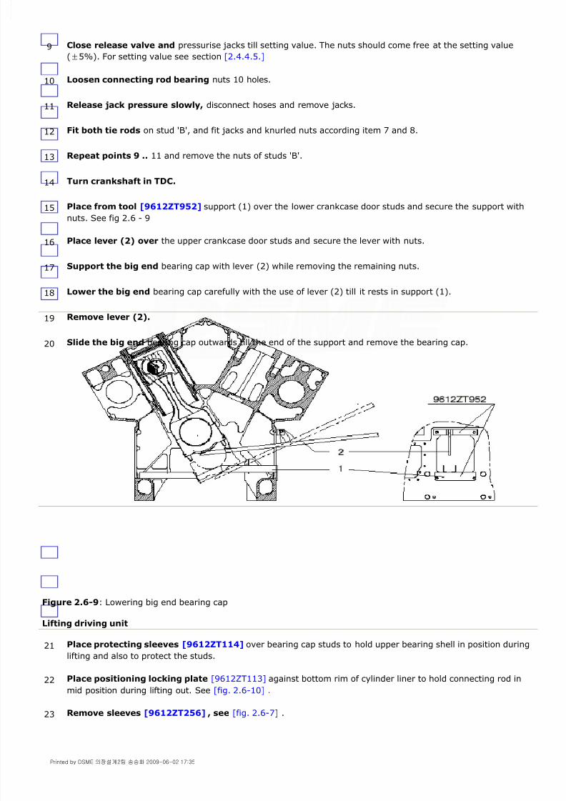
8/9/2019 W26 Instruction Manual
http://slidepdf.com/reader/full/w26-instruction-manual 232/304
P_0000045
Figure 2.6-9: Lowering big end bearing cap
Lifting driving unit
9 Close release valve and pressurise jacks till setting value. The nuts should come free at the setting value
(±5%). For setting value see section [2.4.4.5.]
10 Loosen connecting rod bearing nuts 10 holes.
11 Release jack pressure slowly, disconnect hoses and remove jacks.
12Fit both tie rods on stud 'B', and fit jacks and knurled nuts according item 7 and 8.
13 Repeat points 9 .. 11 and remove the nuts of studs 'B'.
14 Turn crankshaft in TDC.
15 Place from tool [9612ZT952] support (1) over the lower crankcase door studs and secure the support with
nuts. See fig 2.6 - 9
16 Place lever (2) over the upper crankcase door studs and secure the lever with nuts.
17Support the big end bearing cap with lever (2) while removing the remaining nuts.
18 Lower the big end bearing cap carefully with the use of lever (2) till it rests in support (1).
19 Remove lever (2).
20 Slide the big end bearing cap outwards till the end of the support and remove the bearing cap.
21 Place protecting sleeves [9612ZT114] over bearing cap studs to hold upper bearing shell in position during
lifting and also to protect the studs.
22 Place positioning locking plate [9612ZT113] against bottom rim of cylinder liner to hold connecting rod inmid position during lifting out. See [fig. 2.6-10] .
23 Remove sleeves [9612ZT256] , see [fig. 2.6-7] .
Printed by DSME 의장설계2팀 송승화 2009-06-02 17:35

8/9/2019 W26 Instruction Manual
http://slidepdf.com/reader/full/w26-instruction-manual 233/304
P_0000045
Figure 2.6-10: Lifting driving unit
To avoid wrong mounting, connecting bolts are different of length. The threaded holes in the piston crown are
asymmetric positioned.
Note!
If the driving unit does not move easily then carry out the procedure extracting the driving unit.
24 Clean threaded holes in piston crown with tap [9612ZT195] .
25 Fit lifting tool [9612ZT911] with one fixed pin and two sliding pins to cylinder liner and with 2 bolts (12) topiston top, see [fig. 2.6-10] .
26 Place protecting sleeves [9612ZT112] over cylinder head studs, see [fig. 2.6-10] , to protect the cylinder
head studs during lifting.
27 Pull by means of eye bolt (13) on lifting tool [9612ZT911] (see [fig. 2.6-10] ) till the driving unit starts to
move.
28 Lift the driving unit about 10 cm and apply plastic lining to protect water or dirt entering the engine and the
oil supply holes in the crankpin.
29 Continue lifting the driving unit out of the engine taking care not to damage the cylinder liner wall. Observe
that the assembly moves easily without excessive force.
30 Cover the lubricating oil holes in the crankpin against dirt by rubber protecting sheets [9612ZT969] , see
[fig. 2.6-11] .
Printed by DSME 의장설계2팀 송승화 2009-06-02 17:35
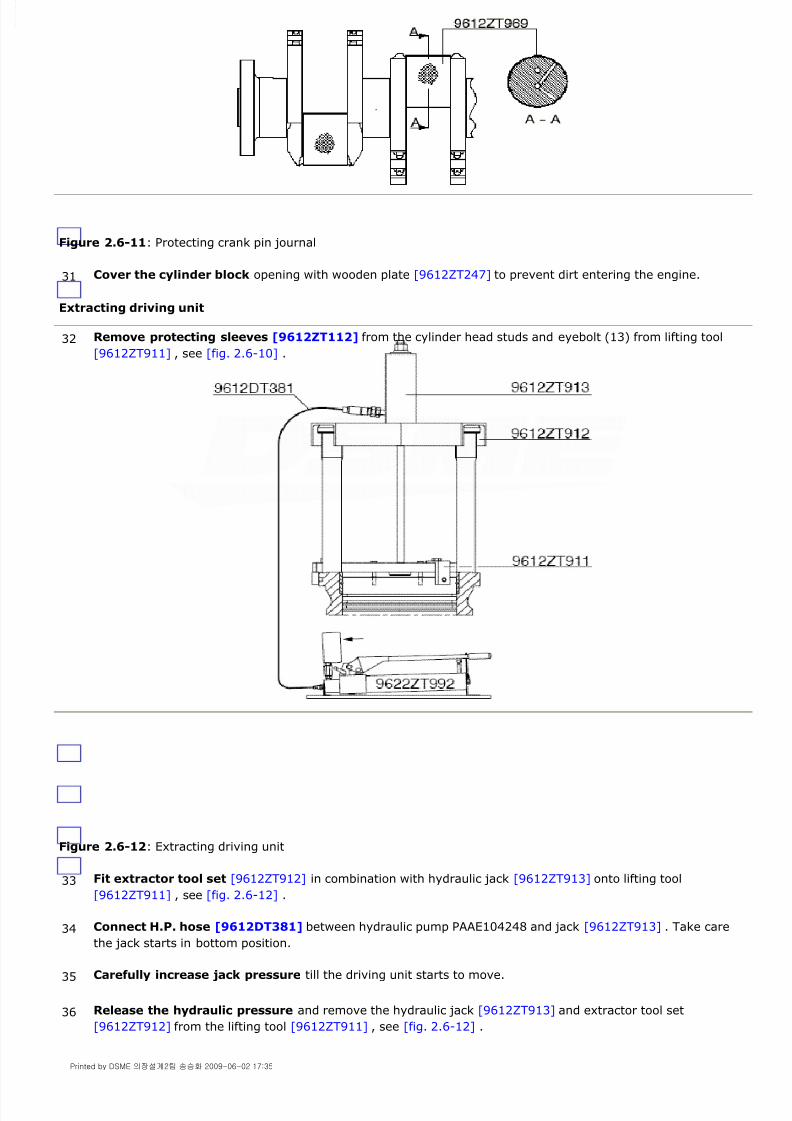
8/9/2019 W26 Instruction Manual
http://slidepdf.com/reader/full/w26-instruction-manual 234/304
P_0000045
Figure 2.6-11: Protecting crank pin journal
Extracting driving unit
Figure 2.6-12: Extracting driving unit
31 Cover the cylinder block opening with wooden plate [9612ZT247] to prevent dirt entering the engine.
32 Remove protecting sleeves [9612ZT112] from the cylinder head studs and eyebolt (13) from lifting tool
[9612ZT911] , see [fig. 2.6-10] .
33 Fit extractor tool set [9612ZT912] in combination with hydraulic jack [9612ZT913] onto lifting tool
[9612ZT911] , see [fig. 2.6-12] .
34 Connect H.P. hose [9612DT381] between hydraulic pump PAAE104248 and jack [9612ZT913] . Take care
the jack starts in bottom position.
35 Carefully increase jack pressure till the driving unit starts to move.
36 Release the hydraulic pressure and remove the hydraulic jack [9612ZT913] and extractor tool set
[9612ZT912] from the lifting tool [9612ZT911] , see [fig. 2.6-12] .
Printed by DSME 의장설계2팀 송승화 2009-06-02 17:35

8/9/2019 W26 Instruction Manual
http://slidepdf.com/reader/full/w26-instruction-manual 235/304
P_0000045
2.6.2.3.Disassembling driving unit
Maintenance work on the connecting rod / piston / cylinder liner assembly, in case tool [9612ZT445] is used.
Keep sleeves [9612ZT114] mounted to protect the connecting rod studs.
Figure 2.6-13: Support driving unit
Maintenance work on the connecting rod / piston / cylinder liner assembly, in case tool [9612ZT445] is not used.
Never compress locking rings more than necessary.
37 Fit eyebolt (13) and place protecting sleeves [9612ZT112] over cylinder head studs to protect the cylinder
head studs during lifting of the assembly, see [fig. 2.6-10] .
38 Continue with "lifting driving unit" point 28.
1 Place the driving unit into support [9612ZT445] . See [fig. 2.6-13] .
2 Remove bolts (12) and locking plate [9612ZT113] .
3 Remove the cylinder liner together with lifting tool [9612ZT911] .
4 Remove the lifting tool from the cylinder liner.
5 Place driving unit horizontal on a flat plywood surface and disconnect lifting tool [9612ZT911] .
6 Turn the driving unit up side down and hoist connecting rod with piston out of cylinder liner.
7 Clean cylinder liner from carbon deposits.
8 Place connecting rod / piston assembly up side down on a flat piece of wood and keep connecting rod vertical
by sling and crane.
9 Remove locking ring (10), see [fig. 2.6-14] .
Printed by DSME 의장설계2팀 송승화 2009-06-02 17:35
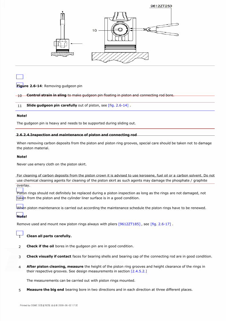
8/9/2019 W26 Instruction Manual
http://slidepdf.com/reader/full/w26-instruction-manual 236/304
P_0000045
Figure 2.6-14: Removing gudgeon pin
Note!
The gudgeon pin is heavy and needs to be supported during sliding out.
2.6.2.4.Inspection and maintenance of piston and connecting rod
When removing carbon deposits from the piston and piston ring grooves, special care should be taken not to damage
the piston material.
Note!
Never use emery cloth on the piston skirt.
For cleaning of carbon deposits from the piston crown it is advised to use kerosene, fuel oil or a carbon solvent. Do not
use chemical cleaning agents for cleaning of the piston skirt as such agents may damage the phosphate / graphite
overlay.
Piston rings should not definitely be replaced during a piston inspection as long as the rings are not damaged, not
taken from the piston and the cylinder liner surface is in a good condition.
When piston maintenance is carried out according the maintenance schedule the piston rings have to be renewed.
Note!
Remove used and mount new piston rings always with pliers [9612ZT185] , see [fig. 2.6-17] .
10 Control strain in sling to make gudgeon pin floating in piston and connecting rod bore.
11 Slide gudgeon pin carefully out of piston, see [fig. 2.6-14] .
1 Clean all parts carefully.
2 Check if the oil bores in the gudgeon pin are in good condition.
3 Check visually if contact faces for bearing shells and bearing cap of the connecting rod are in good condition.
4 After piston cleaning, measure the height of the piston ring grooves and height clearance of the rings in
their respective grooves. See design measurements in section [2.4.5.2.]
The measurements can be carried out with piston rings mounted.
5 Measure the big end bearing bore in two directions and in each direction at three different places.
Printed by DSME 의장설계2팀 송승화 2009-06-02 17:35

8/9/2019 W26 Instruction Manual
http://slidepdf.com/reader/full/w26-instruction-manual 237/304
P_0000045
2.6.2.5.Assembling connecting rod and piston
Position of connecting rod in relation to the crankshaft rotation
Note!
Take good care for the correct pressure in relation with the used hydraulic jacks! See also section [2.4.4.]
Clockwise rotating
For a clockwise rotating engine all connecting rods of 'A' and 'B' bank after mounting into the engine must have their
mark 'OI' (oil inlet) pointing to the 'B'-bank side, see [fig. 2.6-15] .
The 'X' mark on liners and pistons at the 'B' bank must point to the 'B' bank camshaft side.
The 'X' mark on liners and pistons at the 'A' bank must point to the 'A' bank camshaft side.
Figure 2.6-15: Clockwise rotating
This means, before mounting the piston onto the connecting rod, the destination of the connecting rod, piston and
liner assembling must be determined for the 'A' or 'B' bank.
For mounting the unit into the 'B' bank the mark 'X' on the piston crown, the mark 'X' on the liner collar and the 'OI'mark in the connecting rod must all be at one side.
For mounting the unit into the 'A' bank the mark 'X' on the piston crown and the mark 'X' on the liner collar shouldbe at one side and the 'OI' mark in the connecting rod at the opposite side.
Counter clockwise rotating
For a counter clockwise rotating engine all connecting rods of 'A' and 'B' bank after mounting into the engine must
have their mark 'OI' (oil inlet) pointed to the 'A' bank side, see [fig. 2.6-16] .
The 'X' mark on liners and pistons mounted at the 'B' bank must point to the 'B' bank camshaft side.
The 'X' mark on liners and pistons mounted at the 'A' bank must point to the 'A' bank camshaft side.
6 Measure the gudgeon pin diameter in two directions and in each direction at four different places.
7 Measure the small end bearing bore in two directions and in each direction at two different places.
8 Check if the gudgeon pin and small end bearing clearance is within the tolerance. See design measurements
in section [2.4.5.2.]
Printed by DSME 의장설계2팀 송승화 2009-06-02 17:35

8/9/2019 W26 Instruction Manual
http://slidepdf.com/reader/full/w26-instruction-manual 238/304
P_0000045
Figure 2.6-16: Counter clockwise rotating
This means, before mounting the piston onto the connecting rod, the destination of the connecting rod, piston and
liner assembling must be determined for the 'A' or 'B' bank.
For mounting the unit into the 'A' bank the mark 'X' on the piston crown, the mark 'X' on the liner collar and the 'OI'mark in the connecting rod must all be at one side.
For mounting the unit into the 'B' bank the mark 'X' on the piston crown and the mark 'X' on the liner collar shouldbe at one side and the 'OI' mark in the connecting rod at the opposite side.
Note!
Both compression rings (1) and (2) look similar however they are different. Check piston ring part number and
location on piston in the part catalogue, see [fig. 2.6-17] .
Note!
Always mount piston rings with identification number facing top and with the slot opening 120 ° opposite of each
other.
1 Place piston up side down on a flat piece of plywood.
See [fig. 2.6-19] .
2 Lift connecting rod by sling and crane up side down and lower connecting rod slowly into piston.
3 Adjust bores of connecting rod and piston in line.
4 Insert gudgeon pin into piston and connecting rod bore.
5 Refit locking ring (10), see [fig. 2.6-14] .
6 Use piston ring pliers [9612ZT185] to mount compression rings and oil scraper ring in piston ring grooves,
see [fig. 2.6-17] .
7 After mounting the piston rings check if the rings are free moving in piston ring grooves.
Printed by DSME 의장설계2팀 송승화 2009-06-02 17:35

8/9/2019 W26 Instruction Manual
http://slidepdf.com/reader/full/w26-instruction-manual 239/304
P_0000045
Figure 2.6-17: Application piston ring pliers
2.6.2.6.Mounting connecting rod with piston into cylinder liner
Figure 2.6-18: Cylinder liner diameter control
1 Clean cylinder liner inside and outside.
2 Measure the cylinder liner inner diameter in two directions and in each direction at several heights, record
readings. See [fig. 2.6-18] .
For No-Go see section [2.4.5.2.]
3 Place cylinder liner up side down on a flat piece of plywood.
For easy handling and comfortable mounting of piston in cylinder liner, clamp cylinder liner in tool
[9612ZT954] , see [fig. 2.6-19] .
4Turn piston with connecting rod up side down.
5 Divide piston ring slots evenly (120° opposite of each other) over circumference of piston crown.
6 Clean cylinder liner bore and lubricate the surface with engine oil.
Printed by DSME 의장설계2팀 송승화 2009-06-02 17:35

8/9/2019 W26 Instruction Manual
http://slidepdf.com/reader/full/w26-instruction-manual 240/304

8/9/2019 W26 Instruction Manual
http://slidepdf.com/reader/full/w26-instruction-manual 241/304
P_0000045
asymmetric positioned.
Figure 2.6-20: Lowering driving unit
Mounting support ring cylinder liner
6 Fit locking plate [9612ZT113] to keep the connecting rod in the centre line of the cylinder liner and lift the
driving unit on eye bolt (14), see [fig. 2.6-20] .
7 Place connecting rod upper bearing shell in connecting rod and hold shell in position by the four protecting
sleeves [9612ZT114] .
See [fig. 2.6-20] .
8 Observe mark 'X' on cylinder liner is facing camshaft side (operating side).
9 Turn crankshaft into top position of the cylinder concerned, remove rubber protection sheet, check ifcrankpin is clean and undamaged, oil the crankpin.
10 Place protecting sleeves [9612ZT112] over cylinder head studs, see [fig. 2.6-20] , to protect the cylinder
head studs during lowering.
11 Check if contact faces for cylinder liner in the cylinder block at top and bottom side are still clean.
12 Clean carefully the contact faces of the new support ring (2), engine block (1) and cylinder liner (3), see
[fig. 2.6-21] .
Printed by DSME 의장설계2팀 송승화 2009-06-02 17:35

8/9/2019 W26 Instruction Manual
http://slidepdf.com/reader/full/w26-instruction-manual 242/304
P_0000045
Figure 2.6-21: Support ring cylinder liner
Note!
To avoid lifting of the cylinder liner while cranking the engine the sleeves [9612ZT256] must remain mounted until
the cylinder head is mounted.
13 Place the support ring (2) on top of the engine block (1) with the centring lips positioned near the cylinder
head studs (4).
14 Lower driving unit carefully into the cylinder block.
15 Remove lifting tool [9612ZT911] from cylinder liner and piston. The connecting rod bearing is now resting
on the crankpin. See [fig. 2.6-20] .
16 Remove the four protecting sleeves [9612ZT112] from the cylinder head studs, see [fig. 2.6-20] .
17 Fit two sleeves [9612ZT256] over cylinder head studs and turn on cylinder head nuts to press the cylinder
liner D-rings into the cylinder block bore till the collar of the cylinder liner rests on the support ring, see
[fig. 2.6-22] .
Printed by DSME 의장설계2팀 송승화 2009-06-02 17:35

8/9/2019 W26 Instruction Manual
http://slidepdf.com/reader/full/w26-instruction-manual 243/304
P_0000045
Figure 2.6-22: Securing cylinder liner
Mounting big end bearing cap
Note!
The jacks mounted should not rest on or touch the crank webs / counter weights.
Note!
Take good care for the correct pressure in relation with the used hydraulic jacks!
See also section [2.4.4.]
18 Remove connecting rod locking plate [9612ZT113] from cylinder liner rim, see [fig. 2.6-20] .
19 Remove protecting sleeves [9612ZT114] from connecting rod studs, see [fig. 2.6-20] .
20 Check connecting rod bearing cap and place lower bearing shell in cap. Lubricate bearing shell only at
running side with engine oil.
21 Place the big end bearing cap on support (1) of tool [9612ZT952] and slide it inwards against the support
stop. See [fig. 2.6-9] .
22 Place lever (2) over the upper crankcase door studs at each side of the crankcase opening and secure the
lever with nuts.
23 Lift the big end bearing cap carefully with the use of lever (2) against the connecting rod and tighten the nuts
with the tool pin.
24 Remove tool [9612ZT952] .
25 Fit tie rods [9612ZT476] on both connecting rod stud 'A' according [fig. 2.6-8] .
26 Place both jacks [9612ZT944] over tie rods [9612ZT476] and turn knurled nuts [9612ZT477] by hand as far
as possible on the tie rods.
27 Connect H.P. hoses [9612DT381] between jacks and hydraulic pump PAAE104248 according [fig. 2.6-8] and
open release valve at pump.
28 Tighten knurled nuts further on with tool pin to force jack pistons to bottom position.
29 1st step 'A' studs
Printed by DSME 의장설계2팀 송승화 2009-06-02 17:35

8/9/2019 W26 Instruction Manual
http://slidepdf.com/reader/full/w26-instruction-manual 244/304
P_0000045
Pressurise jacks till 500 bar.
Use tool pin [9612ZT125] to tighten the bearing cap nuts.
Check with a feeler blade of 0.05 mm that nuts are on.
Release hydraulic pressure slowly till zero. Give time to the jack pistons to travel to bottom position.
Place jacks on the 'B' studs. Check if the jack pistons are in bottom position.
Pressurise jacks till 500 bar.
Use tool pin [9612ZT125] to tighten the nuts.
Check with a feeler blade of 0.05 mm that nuts are on.
Release hydraulic pressure slowly till zero. Give time to the jack pistons to travel to bottom position.
Remove both jacks from studs 'B'.
Place measuring device [9612ZT940] over each of the studs (A and B) and measure the distance between the nutsurfaces and the end of the studs, measure 'X' and record these measures, see [fig. 2.6-23] .
Place jacks on the 'B' studs. Check if the jack pistons are in bottom position.
Pressurise jacks till setting value, see section [2.4.4.5.] and tighten the nuts. Nut shifting is limited.
Release hydraulic pressure slowly till zero. Give time to the jack pistons to travel to bottom position.
Place jacks on the 'A' studs. Check if the jack pistons are in bottom position.
Pressurise jacks till setting value and tighten the nuts. Nut shifting is limited.
Release hydraulic pressure slowly till zero. Give time to the jack pistons to travel to bottom position.
Pressurise jacks again till setting value and tighten the nuts again. Nut shifting should not exist.
Check with a 0.05mm feeler blade that nuts are on.
Release hydraulic pressure slowly till zero. Give time to the jack pistons to travel to bottom position.
Place jacks on the 'B' studs. Check if the jack pistons are in bottom position.
Pressurise jacks till setting value and tighten the nuts. Nut shifting should not exist.
Check with a 0.05mm feeler blade that nuts are on.
Release hydraulic pressure slowly till zero. Give time to the jack pistons to travel to bottom position.
Remove jacks.
Place measuring device [9612ZT940] over each of the studs (A and B) and measure the distance between the nutsurfaces and the end of the studs, measure 'Y' and record these measures, see [fig. 2.6-23] .
Calculate 'Y' - 'X' the elongation has to be in between limits given in section [2.4.4.5.] ( [fig. 2.4-20] ).
Figure 2.6-23: Measuring stud elongation
Warning!
In case stud elongation is outside limits the connection is NOT safe. In such a case all components have to be
30 1st step 'B' studs
31 2nd step 'B' studs
32 2nd step 'A' studs
33 3rd step 'A' studs
34 3rd step 'B' studs
Printed by DSME 의장설계2팀 송승화 2009-06-02 17:35

8/9/2019 W26 Instruction Manual
http://slidepdf.com/reader/full/w26-instruction-manual 245/304
P_0000045
disconnected and examined on deviation in material or wrong assembling.
2.6.3.Vibration damper crankshaft
The vibration damper serves to reduce the torsional vibration in the crankshaft. The damper consists of a housing and
a free rotating inertia ring supported by an axial and radial bearing. It forms a totally enclosed unit. The free space
between inertia ring and damper housing is filled with a high viscosity fluid. The combustion pressure, exerted on thepistons, causes a torsional vibration in the crankshaft. The energy caused by the vibration, is converted into heat and
cooled by engine lubricating oil at the outside of the vibration damper.
2.6.3.1.Maintenance
The viscous damper fluid is subject to aging during engine operation. In sending fluid samples on a regular base to
Wärtsilä Corporation the change of the viscosity can be determined. In the analysis the quality of the fluid is
mentioned and a forecast is given of the number of running hours still to go.
The damper cover has two sampling plugs located 180° opposed. If one of the sampling plugs is accessible, a fluid
sample can be taken with the damper in situ. For liquid sampling, a kit can be ordered from Wärtsilä Corporation
department under no. 17630 [9622DT472] .
Note!
Dampers with a viscosity out of range may cause crankshaft breakdown.
2.6.3.2.Liquid sampling
It is advisable to take a sample when the engine is still warm.
Proceed as follows:
35 Fit cylinder head, see chapter
36 Fill the cooling water system and check the sealing of D-rings at the cylinder liner bottom on water leakagebefore starting the engine.
37 Start the prelubricating oil pump and check the bearings get oil.
38 Close the crankcase.
1 Bar the crankshaft until a sampling plug is easy accessible.
2 Remove the lubricating oil pump if neither of the sampling plugs in the damper is accessible for sampling.
3 Remove locking of sampling plug, using a punch and unscrew plug with spanner [9612ZT497] . Do not yet
remove plug!
4 Unscrew one cap nut from (plastic) liquid container, the thread of which corresponds to that of the sampling
plug in the damper. The sides of the liquid container have various threads for other damper types.
5 Remove sampling plug and screw liquid container instead.
Printed by DSME 의장설계2팀 송승화 2009-06-02 17:35

8/9/2019 W26 Instruction Manual
http://slidepdf.com/reader/full/w26-instruction-manual 246/304
P_0000045
Figure 2.6-24: Liquid sampling
If no liquid appears:
Remove second sampling plug.
Supply nitrogen of 3.5 bar maximum pressure through the open second sampling plug hole. If no nitrogen isavailable air may be used provided this air is properly filtered and dry.
If a liquid sample can not be obtained in this way it can be assumed that the damper liquid has thickened to much.
In this case the damper has to be replaced.
Cut off the nitrogen/air if applicable. Screw the outer cap nut onto the liquid container.
serial number of the vibration damper (if possible)
engine type
engine number
number of operating hours
6 Remove the outer cap nut from the liquid container. Make sure that no machine oil or dirt can enter while
filling the liquid container!
7 The filling period of the container may take from a few seconds up to more than an hour depending on liquid
condition.
8 Once the liquid has reached the open end of the liquid container:
9 Unscrew the container from the damper and fit the second cap onto the container.
10 Fit the damper sampling plug(s) with new joint ring(s) supplied with the mounting kit. Replace any damaged
sampling plug if necessary.
11 Tighten the sampling plugs at a torque of 35 Nm.
12 Lock the sampling plugs.
13 After sampling, provide the sample with a label (included in the sampling kit) showing the following data :
Printed by DSME 의장설계2팀 송승화 2009-06-02 17:35

8/9/2019 W26 Instruction Manual
http://slidepdf.com/reader/full/w26-instruction-manual 247/304
P_0000045
date of sampling
Forward the sample to : Wärtsilä Italia S.p.A.
Service Department
Bagnoli della Rosandra, 334
34018 San Dorligo della Valle
Trieste - Italy
Once we have examined the sample the result will be reported to you in writing. This report will also include our
recommendation.
2.6.4.Turning gear
Engine cranking is done by means of an electrical motor which drives a gearbox (5).
For fine adjustment of the crankshaft use the hexagon spindle (3).
The engaging and disengaging of the turning gear is done by operating lever (1) and is secured by a locking pin (2),
see [fig. 2.6-25] .
An electrically start interlock (6) and a pneumatically start interlock (7) block the engine start in case the turning gear
is engaged.
Figure 2.6-25: Turning gear
Life time of worm gear units depends to a great extent on the grade of oil used. Use only the grade of oil stated on the
instruction plate.
The gear units are maintenance free under normal operating conditions. They should be checked for leakages at
certain intervals.
14 Max. 10 liquid samples of 1 cm³ each are allowed to be taken.
Printed by DSME 의장설계2팀 송승화 2009-06-02 17:35

8/9/2019 W26 Instruction Manual
http://slidepdf.com/reader/full/w26-instruction-manual 248/304
P_0000045
The applied gear unit is filled with a synthetic lubricant. If topping-up is necessary a synthetic lubricant should be used
in accordance with the instruction plate.
See also section [1.2.1.1.2.] for the recommended lubricating oil.
Maintenance
1 Grease the nipple (4) on the hub of the gearwheel only at disengaged turning gear. This to avoid an overdose
of grease behind the gearwheel shaft.
2 Check, with the engine not in operation, by engaging and disengaging a few times, the turning gear moves
smoothly on the shaft.
3 Check the locking pin (2) of the engaging lever (1) is smooth and correctly working.
Printed by DSME 의장설계2팀 송승화 2009-06-02 17:35

8/9/2019 W26 Instruction Manual
http://slidepdf.com/reader/full/w26-instruction-manual 249/304
P_0000045
2.7.1.Cylinder head
The cylinder head is provided with two inlet valves(1) and two exhaust valves (2) with valve rotators (10) and bridge
pieces (11), a fuel injector (3), a safety valve (25) and an indicator cock (26). The cylinder head and the exhaust
valves seats (4) are cooled by HT cooling water. See [fig. 2.7-1] and [fig. 2.7-8] .
HT cooling water is supplied from the engine block to the cylinder head by means of a free inserted interconnecting
pipe (27) between engine block and cylinder head. HT cooling water is discharged through an outlet channel (6) at the
upper side of the cylinder head via a multiduct, back to the engine block. Integrated in the multiduct are the charge
air, exhaust gas and cooling water connections, the multiduct remains normally connected to the engine block. By
removing 6 bolts the cylinder head is disconnected from the the multiduct.
The valve lifting gear (7) is mounted to the cylinder head by two bolts and is described in chapter [2.8.]
A single pipe connects cylinder head with the engine lubricating oil system and takes care for lubrication of valve lifting
gear, bridge pieces, valves and valve stems.
Figure 2.7-1: Cross section cylinder head
2.7.1.1.Maintenance of cylinder head
Cylinder head maintenance consists mainly in measurement checks, cleaning, grinding of sealing surfaces and
maintenance of cylinder head components.
Scale formation in cooling water spaces will disturb the cooling effect. Cleaning can be realised by chemical solvents.
Contact a specialised company for chemical cleaning.
When scale formation exists observe the cooling water treatment.
A comfortable manner of doing maintenance to cylinder heads is with the aid of a tilting frame [9612ZT958] . After
placing the cylinder head onto the tilting frame fixate the head by 2 nuts and rings (12).
The cylinder head can be turned over and fixed in position by means of locking pin (13) in one of the holes (14).
2.7.Cylinder Head with Valves 2.7-PAAE062665-00
Printed by DSME 의장설계2팀 송승화 2009-06-02 17:35

8/9/2019 W26 Instruction Manual
http://slidepdf.com/reader/full/w26-instruction-manual 250/304

8/9/2019 W26 Instruction Manual
http://slidepdf.com/reader/full/w26-instruction-manual 251/304
P_0000045
Figure 2.7-3: Disconnecting pipes from cylinder head
Figure 2.7-4: Cylinder head with 4 jacks
8 Remove protecting caps from cylinder head studs. Make sure the thread of the cylinder head studs is clean
and free of damage.
9 Remove push rods.
10 Fit from tool set [9612ZT904] , hydraulic jacks [9612ZT901] together with tie rods [9612ZT131] and distance
pieces [9612ZT196] . Connect HP hoses according [fig. 2.7-4] (in case of applying 4 jacks) or according
[fig. 2.7-10] (in case of 2 jacks).
11 Open bleed-off valve on hydraulic pump and tighten knurled nuts [9612ZT119] completely to force jack
pistons into bottom position, see [fig. 2.7-4] . After jack pistons are at bottom position turn knurled nuts 6 holes
counter clockwise.
12 Pressurize jacks to setting value and turn cylinder head nuts
8 holes counter clockwise with tool pin [9612ZT125] .
13 Lower pressure slowly till zero and remove tool set.
14 Remove cylinder head nuts.
Printed by DSME 의장설계2팀 송승화 2009-06-02 17:35

8/9/2019 W26 Instruction Manual
http://slidepdf.com/reader/full/w26-instruction-manual 252/304
P_0000045
Figure 2.7-5: Lifting cylinder head
Figure 2.7-6: Securing cylinder liner
15 Use lifting tool [9612ZT927] to remove cylinder head from engine. See [fig. 2.7-5] . The cylinder head
should be lifted in line in relation to the centre line to avoid damage to the cylinder head studs and cooling
water interconnecting pipe.
16 Check if cooling water interconnecting pipe (27) is free. Support both push rod protecting pipes (23) till
cylinder head is completely free from the engine to avoid lifting damage. See [fig. 2.7-8] .
17 Whenever a cylinder head is removed place both sleeves [9612ZT256] over the cylinder head studs and
secure them with cylinder head nuts to keep the liner in place in case of cranking the engine, see [fig. 2.7-6] .
Printed by DSME 의장설계2팀 송승화 2009-06-02 17:35

8/9/2019 W26 Instruction Manual
http://slidepdf.com/reader/full/w26-instruction-manual 253/304
P_0000045
Figure 2.7-7: Cylinder liner cover
2.7.1.3.Mounting cylinder head
Figure 2.7-8: Cylinder head build-on
18 Cover liner with wooden plate [9612ZT247] .
19 Use tool [9612ZT877] to remove the cooling water interconnecting pipe (27). See [fig. 2.7-8] .
1 Clean all sealing surfaces of cylinder head, liner and multiduct connections.
2 Fit new O-rings (20) and (30) with silicon grease on cooling water interconnecting pipe, see [fig. 2.7-8] .
Printed by DSME 의장설계2팀 송승화 2009-06-02 17:35

8/9/2019 W26 Instruction Manual
http://slidepdf.com/reader/full/w26-instruction-manual 254/304
P_0000045
Mounting procedure with 4 jacks
Cylinder head studs
Pressurize jacks till 300 bar.
Firmly tighten all 4 cylinder head nuts with tool pin. Check with a feeler blade of 0.05 mm that nuts are fullytightened.
Slowly lower jack pressure till zero. Take care jack pistons travels till bottom position and remove the hydraulictools.
Place measuring device [9612ZT941] over each of the studs and measure the distance between the nut surfacesand the end of the studs, measure 'X' and record these measures, see [fig. 2.7-9] .
Fit hydraulic tools and make sure that the pistons of the jacks are in bottom position and increase jack pressure till
setting value, see chapter [2.4.] Firmly tighten all 4 cylinder nuts further on.
Slowly lower pressure till zero.Take care the jack pistons travel till bottom position.
Increase jack pressure till setting value and shift nuts with tool pin further on. This should be possible over a fewdegrees only.
Check with a feeler blade of 0.05 mm that no clearance exists between cylinder head and nut.
Slowly lower pressure till zero. Take care jack pistons travel till bottom position.
Remove the hydraulic tools.
Place measuring device [9612ZT941] over each of the studs and measure the distance between the nut surfacesand the end of the studs, measure 'Y' and record these measures, see [fig. 2.7-9] .
Difference in elongation between 'Y' and 'X' has to be in between limits given in chapter [2.4.] 4., see [fig. 2.7-9] .
3 Fit new O-rings (21) with silicon grease in push rods fittings. Renew and lubricate V-rings (22) with silicon
grease and place push rod protecting pipes (23) in position.
4 Turn piston in TDC combustion to be sure the tappet rollers for in and exhaust rest on the base circle.
5 Mount lifting tool [9612ZT927] to cylinder head, see [fig. 2.7-5] .
6 Place a new gas sealing ring (24) on top of liner with centring lips positioned near cylinder head studs (29).
See [fig. 2.7-8] view A-A.
7 Place a new gasket on the multiduct and fix it with two clips. See section [1.5.5 ] multiduct sealing.
8 During lowering the cylinder head on liner take care push rod protecting pipes slide into O-rings and the
cooling water interconnecting pipe (27) slides in cylinder head bore without hampering.
9 Fit cylinder head nuts and tighten firmly with tool pin [9612ZT125] .
10 Apply heat resistant compound on the exhaust bolts. Turn bolts for inlet and exhaust from multiduct intocylinder head do not tighten the bolts.
11 Fit hydraulic tools according [fig. 2.7-4] .
12 Open bleed off valve at hydraulic pump and tighten knurled nuts completely to force jack pistons into bottom
position before pressurizing.
13 1st step
14 2nd step
15 3rd step
Printed by DSME 의장설계2팀 송승화 2009-06-02 17:35

8/9/2019 W26 Instruction Manual
http://slidepdf.com/reader/full/w26-instruction-manual 255/304
P_0000045
Figure 2.7-9: Stud elongation
Warning!
In case difference in elongation is outside limits as mentioned in chapter [2.4.] 4. the connection is NOT safe. In such
a case all components have to be disconnected and examined on deviation in material or wrong assembling.
Mounting procedure with 2 jacks
Cylinder head studs
Pressurize jacks till 300 bar.
Firmly tighten both nuts 'A' with tool pin.
Check with a feeler blade of 0.05 mm that nuts are fully tightened.
Slowly lower jack pressure till zero. Take care jack pistons travel till bottom position.
Remove hydraulic tools.
Figure 2.7-10: Cylinder head with 2 jacks
Tighten nuts handtight with tool pin.
Fit hydraulic tools on the 'B' studs and tighten knurled nuts completely to force jack pistons to bottom position.
Pressurize jacks till 300 bar.
Firmly tighten both 'B' nuts with tool pin.
16 Fit of tool set [9612ZT904] hydraulic tools according [fig. 2.7-10] . Open bleed off valve at hydraulic pump
and tighten knurled nuts completely to force jack pistons to bottom position.
17 1st step 'A' studs
18 1st step 'B' studs
Printed by DSME 의장설계2팀 송승화 2009-06-02 17:35
8/9/2019 W26 Instruction Manual
http://slidepdf.com/reader/full/w26-instruction-manual 256/304
8/9/2019 W26 Instruction Manual
http://slidepdf.com/reader/full/w26-instruction-manual 257/304

8/9/2019 W26 Instruction Manual
http://slidepdf.com/reader/full/w26-instruction-manual 258/304
P_0000045
Figure 2.7-11: Valve clearance adjustment
2.7.3.Valves and valve seats
The valve stem is guided in the valve guide (4). O-ring (5) takes care for the distribution of the lubricating oil between
valve guide and valve stem and prevents gasses to escape from the cylinder head. The valve guides and the valve
seat inserts are frozen in the cylinder head.
A valve rotator (6) rotates the valve to ensure smooth and even wear. The valve rotator is fixed to the valve by means
of valve collets (7).
Note!
Inlet (1) and exhaust (2) valves differ in material and must not be mixed. Inlet valves are larger in valve disc
diameter.
Printed by DSME 의장설계2팀 송승화 2009-06-02 17:35

8/9/2019 W26 Instruction Manual
http://slidepdf.com/reader/full/w26-instruction-manual 259/304
P_0000045
Figure 2.7-12: Valves and valve seats
2.7.3.1.Removing of valves
After the cylinder head is taken from the engine and the injector removed, see section [2.9.3.2.] , the valves can be
removed.
1 After the valve lifting gear is removed mount tool set [9612ZT919] in combination with jack [9612ZT913] to
the cylinder head, see [fig. 2.7-13] .
2 Fit tool [9612ZT145] over valve spring sets and place centering bush in hole of injector.
3 Fixate construction to cylinder head by 2 nuts to injector studs.
4 Leave about 40 mm distance between jack and nut to allow the springs to expand after removal of the valve
collets (7).
Use hydraulic pump [9622ZT992] to compress spring assembly and to remove valve collets.
Printed by DSME 의장설계2팀 송승화 2009-06-02 17:35
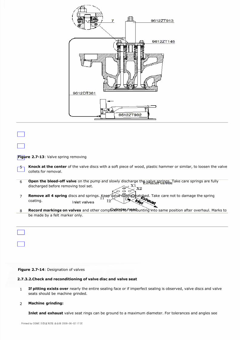
8/9/2019 W26 Instruction Manual
http://slidepdf.com/reader/full/w26-instruction-manual 260/304
P_0000045
Figure 2.7-13: Valve spring removing
Figure 2.7-14: Designation of valves
2.7.3.2.Check and reconditioning of valve disc and valve seat
5 Knock at the center of the valve discs with a soft piece of wood, plastic hammer or similar, to loosen the valve
collets for removal.
6 Open the bleed-off valve on the pump and slowly discharge the valve springs. Take care springs are fully
discharged before removing tool set.
7 Remove all 4 spring discs and springs. Keep valve collets matched. Take care not to damage the spring
coating.
8 Record markings on valves and other components for remounting into same position after overhaul. Marks to
be made by a felt marker only.
1 If pitting exists over nearly the entire sealing face or if imperfect sealing is observed, valve discs and valveseats should be machine grinded.
2 Machine grinding:
Inlet and exhaust valve seat rings can be ground to a maximum diameter. For tolerances and angles see
Printed by DSME 의장설계2팀 송승화 2009-06-02 17:35

8/9/2019 W26 Instruction Manual
http://slidepdf.com/reader/full/w26-instruction-manual 261/304
P_0000045
Note!
Manual grinding is not permitted in order to maintain difference in valve seat angle.
Machine grinding tools are available through Wärtsilä Corporation Service Department or through your local Wärtsilä
Service Office.
For execution of machine grinding see instruction manual included in the tool box grinding machine.
Figure 2.7-15: Blueing test
2.7.3.3.Valve seats
Valve seats are mounted into the cylinder head by means of a shrinking process and fits in the cylinder head with high
force.
Removing of the exhaust valve seat
figures 2.4 - 34 and 2.4 - 35 .
Replace rings after exceeding the maximum diameter.
3 Blueing test:
Apply marginal Prussian Blue on the contact surface of the valve disc. Place the valve in the cylinder head
and make a contact print by slamming the valve onto the valve seat. Do not rotate the valve.
The obtained contact area should be between 20% and 40%, for inlet valve as well as exhaust valve seats, see[fig. 2.7-15] .
1 Turn the cylinder head up side down. Clean inner side of the valve seat and place from tool set
[9612ZT859] , disc set (1), tie rod (2) in the valve seat and secure the discs by tightening nut (3) with a torque
of 100 Nm. See [fig. 2.7-16] .
2 Place bridge piece (4), hydraulic jack [9612ZT913] and connect to pump [9622ZT992] .
3 Apply pressure till 450 bar if necessary release pressure and increase slowly the pressure again till max
520 bar. If needed repeat this procedure a few times to loosen the seat. Pull the valve seat (5) out of the
cylinder head.
4 Loosen nut (3) and remove the seat from the tool.
5 Clean and degrease valve recesses in cylinder head and check diameter in two directions at two heights.
Compare diameters with nominal dimensions mentioned in section [2.4.5.] [fig. 2.4-35] .
Printed by DSME 의장설계2팀 송승화 2009-06-02 17:35

8/9/2019 W26 Instruction Manual
http://slidepdf.com/reader/full/w26-instruction-manual 262/304

8/9/2019 W26 Instruction Manual
http://slidepdf.com/reader/full/w26-instruction-manual 263/304

8/9/2019 W26 Instruction Manual
http://slidepdf.com/reader/full/w26-instruction-manual 264/304
P_0000045
Figure 2.7-18: Extracting valve stem guide
Mounting valve guide
Mounting process for inlet and exhaust valve stem guide is similar.
Note!
Wear low temperature resistance gloves and safety glasses during handling of deep frozen engine parts and take
notice of the safety measures of the suppliers from the liquid nitrogen.
Note!
If the valve guide is renewed the contact faces of the valve disc and seat have to be checked by the blueing test, see
section [2.7.3.2.]
2.7.3.5.Assembling of valves
4 Apply pressure on jack [9612ZT913] and continue till the guide is extracted from the cylinder head.
5 Clean and degrease valve stem guide recess in cylinder head.
6 Heat cylinder head equally, preferably in a stove till 90°C.
7 Cool valve guide in liquid nitrogen till bubbling stops (-150°C).
8 Oil valve guide recess in cylinder head scarcely.
9 Place valve guide on tool [9612ZT233] for inserting into the cylinder head. Leave pin inserted and check with
some light hammer strokes the guide is completely inserted, see section [2.4.2.7.]
10 Mount the valve spring washer of the valve rotator, see [fig. 2.7-21] .
1 Check valve springs on cracks and wear marks. Replace springs in case of wear marks or other damage.
2Clean valve guides thoroughly and fit new O-rings (13).
Printed by DSME 의장설계2팀 송승화 2009-06-02 17:35

8/9/2019 W26 Instruction Manual
http://slidepdf.com/reader/full/w26-instruction-manual 265/304
P_0000045
Figure 2.7-19: Valve stem guide
2.7.4.Valve rotators
Exhaust and inlet valves are provided with valve rotators devices. These devices slowly rotate the valves during engine
operation. The valve rotation results in an even wear pattern with a better metallic contact between valve and valve
seat. The rotating of the valves improves the running behavior and in turn considerably extends the maintenance
interval period of the valve.
The valve rotators for inlet and exhaust are similar. In both cases the valve rotator rotates the valves only during the
opening process of the valves.
During maintenance only use engine oil for lubrication. Don't grease the steel balls of the rotator bearings as this may
result in a less effective working of the rotator.
Valve rotators should periodically be checked on good working i.e. the valve rotates slowly during engine operation.Before an overhaul remove cylinder head cover and check rotation of all valves. Check during each valve maintenance
the valve rotator on wear. During maintenance work, keep the rotator components as a set and do not mix with parts
of other sets.
2.7.4.1.Inlet valve-, exhaust valve rotator
Maintenance of valve rotator
3 Lubricate valve stems with clean engine oil.
4 Fit valves and check the free movement. Before the valve touches the valve seat seat be sure the seat
surfaces are absolute clean. Replace valves in their original locations.
5 Carry out the blueing test, see section
6 Make sure the contact surfaces of springs, spring discs and valve rotators are undamaged and clean. Installsprings and valve rotators.
7 Place assembling tool [9612ZT919] in combination with jack [9612ZT913] in position, see [fig. 2.7-13] .
8 Compress valve springs and fit valve collets.
9 Unload springs slowly. Check if valve collets do fit properly during unloading of the springs and clearances
between the two valve collets halves is equal.
1 After removal of the valve collets (7) the valve rotator assembly can be removed, see [fig. 2.7-20] .
2 Turn assembly up side down on a workbench.
3 Remove spring locking wire (6).
4 Remove cover plate (2).
5 Remove spring disc (3).
Printed by DSME 의장설계2팀 송승화 2009-06-02 17:35

8/9/2019 W26 Instruction Manual
http://slidepdf.com/reader/full/w26-instruction-manual 266/304
P_0000045
Figure 2.7-20: Inlet valve rotator
Removing/mounting the valve spring washer of the valve rotator
After removal of the valve rotator, the spring, valve and spring disc can be removed/mounted with tool [9612ZT947] .
Turn tool and spring disc counter clockwise for removal and clockwise for mounting.
Figure 2.7-21: Removing/mounting of valve spring washer
2.7.5.Injector sleeve
2.7.5.1.Maintenance
Every time an injector is extracted from the cylinder head the sealing surface at the bottom of the cylinder head has to
be cleaned and inspected to be sure of a gas tight sealing against the high combustion pressures.
One of the possibilities to reface the seal is to lap the surface with a fine grinding compound in combination with
grinding tool [9612ZT962] .
6 Remove steel balls (4) and springs (5).
7 Clean base plate (1) and other components.
8 Check components on wear and damage. Renew the entire unit in case a single component is worn.
9 During first running of the engine after maintenance check if the valve rotator revolves.
Printed by DSME 의장설계2팀 송승화 2009-06-02 17:35

8/9/2019 W26 Instruction Manual
http://slidepdf.com/reader/full/w26-instruction-manual 267/304

8/9/2019 W26 Instruction Manual
http://slidepdf.com/reader/full/w26-instruction-manual 268/304
P_0000045
Figure 2.7-23: Extracting injector sleeve
2.7.5.3.Mounting injector sleeve
1 Clean and degrease injector sleeve and injector sleeve recess in cylinder head.
2 Heat cylinder head till 90°C.
3 Cool injector sleeve till -50°C.
4 Apply sealing compound at outer circumferences of the sleeve in contact with the cylinder head. Remove
sealing compound in excess.
5 Place sleeve on tool [9612ZT946] and insert sleeve into cylinder head.
6 Tighten nut (1) and keep sleeve compressed in cylinder head during at least 5 min.
Printed by DSME 의장설계2팀 송승화 2009-06-02 17:35

8/9/2019 W26 Instruction Manual
http://slidepdf.com/reader/full/w26-instruction-manual 269/304
P_0000045
Figure 2.7-24: Mounting new injector sleeve
2.7.6.Indicator cock and Safety valve
Indicator cock
Each cylinder head is provided with an indicator cock (1), see [fig. 2.7-25] . The inside construction is such that
pressure in the cylinder closes the valve. Consequently the force needed to close the valve is relatively low.
Figure 2.7-25: Indicator cock / safety valve
Safety valve
1 Before starting the engine close the indicator cocks with just enough force to bring the sealing surfaces
together. The cylinder pressure will further close the cock.
2 After an engine stop open the indicator cocks only half a turn.
3 Avoid inadvertent tightening during measuring cylinder pressures.
4 Add high temperature resistant lubricant (up to 1000°C) to spindle threads when it gives friction.
5 Always use tool [9612SW510] to open and close the indicator cocks (1), see [fig. 2.7-25] .
Printed by DSME 의장설계2팀 송승화 2009-06-02 17:35

8/9/2019 W26 Instruction Manual
http://slidepdf.com/reader/full/w26-instruction-manual 270/304
P_0000045
Each cylinder head is provided with a spring loaded safety valve (2). This valve emits an alarming sound at excessive
cylinder pressures. The blow-off pressure is stamped in top of the valve. If safety valves during operation are leaking,
replace at once. Mount the valve with a high temperature resistance lubricant.
Printed by DSME 의장설계2팀 송승화 2009-06-02 17:35

8/9/2019 W26 Instruction Manual
http://slidepdf.com/reader/full/w26-instruction-manual 271/304
P_0000045
2.8.1.Camshaft driving gear
The camshaft is driven by the crankshaft through gear wheels. The gearing consists of a split gear wheel (1) on the
crankshaft, an intermediate gear wheel (2) and a camshaft gear wheel (3), see [fig. 2.8-1] . The camshaft rotates in
the same direction as the crankshaft at half the speed.
Figure 2.8-1: Gearwheel drive camshaft
The camshaft is assembled of camshaft sections (4) and camshaft journals (5) which are connected by bolts (6), see
[fig. 2.8-2] . The camshaft sections are per camshaft identical.
Each cylinder has its own camshaft section in which is integrated the fuel, exhaust and inlet cam. The camshaft journals are not identical in relation to the position of the locating pins (7) on both sides of the camshaft journal. The
position of the locating pins determine the firing order.
It is therefore that the camshaft journals have to be remounted to their original position or replaced by a similar
camshaft journal.
2.8.Camshaft and Valve Drive 2.8-PAAE062665-00
Printed by DSME 의장설계2팀 송승화 2009-06-02 17:35

8/9/2019 W26 Instruction Manual
http://slidepdf.com/reader/full/w26-instruction-manual 272/304
P_0000045
Figure 2.8-2: Camshaft
At the driving end of the camshaft an axial bearing is located consisting of two equal bearing bushes with collar (8),
see fig .2.8 - 2 .
For the correct position and part number of the camshaft journals consult the parts catalogue.
For lubrication of camshaft and camshaft drive see chapter [1.2.]
Note!
For maintenance background information, safety aspects, intervals, tolerances, inspections, and torque spanner
instructions, see chapter [2.4.]
2.8.1.1.Crankshaft gear wheel
The crankshaft gear wheel consists of two parts (9) connected together with bolts (10) and to the crankshaft flange
with bolts (11) see [fig. 2.8-3] . The crankshaft gear wheel can be changed part by part.
Figure 2.8-3: Crankshaft gear wheel
Inspection camshaft driving gear
Inspect the gear wheels, camshaft sections and camshaft journals according the maintenance schedule for clearance
and possible wear, see chapter [2.4.] Early detection and replacement of damaged parts will prevent serious damage.
2.8.1.2.Camshaft gear wheel
2.8.1.2.1.Removing of camshaft gear wheel
Warning!
Printed by DSME 의장설계2팀 송승화 2009-06-02 17:35

8/9/2019 W26 Instruction Manual
http://slidepdf.com/reader/full/w26-instruction-manual 273/304
P_0000045
Turning the crankshaft with disconnected camshaft can result in damaging of in- and exhaust valves.
Figure 2.8-4: Removing camshaft gear wheel
1 Engage turning gear.
2 Remove all cylinder head upper covers and take all rocker arm brackets from the cylinder heads of the
concerning bank, see chapter [2.7.]
3 For the A-bank side remove speed pick-up sensors out of camshaft gear wheel cover, disconnect and removebooster and air bottle for access to camshaft end cover.
Empty sump of governor before disconnecting booster oil lines.
4 For the B-Bank side remove the lubricating oil pipe between filter and end cover.
5 Remove the concerned camshaft gear wheel cover.
6 Bar the crankshaft in TDC of cylinder number "1" and place proper markings on camshaft gear wheel and
intermediate gearwheels.
7 Remove all connecting bolts (10) between camshaft gear wheel and journal completely except one bolt, see
[fig. 2.8-5] .
8 Apply tool [9612ZT377] on the remaining bolt. Separate journal male from camshaft gear wheel recess and
check if locating pin (11) is free, see [fig. 2.8-5] .
9 Remove the tool and the remaining bolt from the camshaft journal.
10 Remove crankcase cover of the gear wheel drive and place bracket of tool [9612ZT964] on studs of
crankcase cover no.1, see [fig. 2.8-4] .
11 Connect hinges of lever [9612ZT988] on suspension point of tool [9612ZT964] . Check free swing of leverfrom vertical till horizontal and backwards.
12 Connect the lifting eye of tool [9612ZT988] to a chain block or crane. Check again free swing of lever.
13 Connect gripping device (3) of tool [9612ZT988] to shaft section of camshaft wheel. If necessary adjust the
height with eccentric shaft (1).
14 Secure position of tool [9612ZT888] to keep camshaft gear wheel assembly in position.
Remove cover (4) for access to camshaft axial bearing, see [fig. 2.8-5] .
Printed by DSME 의장설계2팀 송승화 2009-06-02 17:35

8/9/2019 W26 Instruction Manual
http://slidepdf.com/reader/full/w26-instruction-manual 274/304

8/9/2019 W26 Instruction Manual
http://slidepdf.com/reader/full/w26-instruction-manual 275/304
P_0000045
Note!
As connection between crankshaft and camshaft still not exist, barring of crankshaft is only permitted within a few
crankshaft degrees.
2.8.2.Camshaft
2.8.2.1.Maintenance
Inspect the camshaft according maintenance schedule, see chapter [2.4.] Make visual inspections of cams, tappets
and rollers. A camshaft section has to be replaced when the cam surface profile is damaged. Early detection can
prevent a serious damage.
2.8.2.2.Removing camshaft section and journal
Camshaft section
2 Connect the lifting eye of tool [9612ZT988] to a chain block or crane.
3 Check full swing of lever.
4 Place lever horizontal and mount camshaft gear wheel into bracket of lever. Tighten the bracket bolts.
5 Lift lever with camshaft gear wheel till it rests into teeth of intermediate wheel. If necessary adjust the
height with eccentric shaft (1). See [fig. 2.8-4] .
6 Check if markings on camshaft and intermediate gearwheels are in line, see point 6 of section
7 Slide end journal (8) against flange of camshaft wheel and turn in bolts (7), see fig 2.8 - 5 . If necessary
rotate eccentric shaft (1) of tool [9612ZT964] in lever hinge for lining camshaft wheel to end journal. Lock
eccentric shaft position by bolts (2).
8 Remove lever [9612ZT988] and bracket [9612ZT964] .
9 Bar crankshaft manually into the position till locating pin (11) fits into the locating pin hole, see [fig. 2.8-5] ,
and bolts (10) can be inserted for connection with the camshaft journal.
10 Tighten all bolts (10) according procedure prescribed in
section [2.8.2.3.]
11 Tighten all bolts (7).
12 Mount thrust disc (5) with bolts (6).
13 Check axial clearance, see chapter
14 Mount end cover (4).
15 Check timing.
16 Mount all remaining parts in reversed order.
17 Dis-engage turning gear.
1 Turn the fuel cam, of the camshaft section to be removed, in top and install tool [9612ZT925] to keep the fuel
pump tappet roller free from the fuel cam, see section [2.9.2.1.]
2 Turn the inlet and exhaust cam one by one in top and install tool [9612ZT924] to keep the inlet en exhaust
Printed by DSME 의장설계2팀 송승화 2009-06-02 17:35
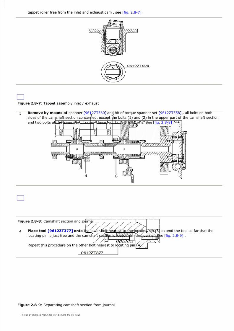
8/9/2019 W26 Instruction Manual
http://slidepdf.com/reader/full/w26-instruction-manual 276/304
P_0000045
Figure 2.8-7: Tappet assembly inlet / exhaust
Figure 2.8-8: Camshaft section and journal
Figure 2.8-9: Separating camshaft section from journal
tappet roller free from the inlet and exhaust cam , see [fig. 2.8-7] .
3 Remove by means of spanner [9612ZT560] and bit of torque spanner set [9612ZT558] , all bolts on bothsides of the camshaft section concerned, except the bolts (1) and (2) in the upper part of the camshaft section
and two bolts at the lower part. Loosen these four bolts 3 full turns. See [fig. 2.8-8] .
4 Place tool [9612ZT377] onto the lower bolt nearest to the locating pin (3) extend the tool so far that the
locating pin is just free and the camshaft section is loose from the journal. See [fig. 2.8-9] .
Repeat this procedure on the other bolt nearest to locating pin (4).
Printed by DSME 의장설계2팀 송승화 2009-06-02 17:35

8/9/2019 W26 Instruction Manual
http://slidepdf.com/reader/full/w26-instruction-manual 277/304
P_0000045
Figure 2.8-10: Tool for camshaft section
Removing camshaft journal
Before removing the camshaft journal first remove the camshaft sections at both sides of the journal according
previous description.
Figure 2.8-11: Sliding out camshaft journal
2.8.2.3.Mounting camshaft section and journal
Warning!
Not all camshaft journals are identical! Before mounting, check the parts catalogue for correct location of camshaft
journal.
Camshaft journal
5 Mount tool [9612ZT986] against the camshaft casing. Fine adjust the lever with bolt (3) for easy removal of
the four bolts. See [fig. 2.8-10] .
6 The camshaft section is now fully resting on the lever and can be moved to the outside. Use sling and crane
to lift the camshaft section.
7 Mount tool [9612ZT987] against the camshaft casing, see [fig. 2.8-11] . Slide the journal out of the bearing
bush onto this tool and to the outside of the engine.
1 Inspect if the bearing bush is free from damage. For inspection and mounting of bearing bush see chapter
[2.5.]
2 Clean journal and the threaded holes. Check if the locating pin holes are not damaged. Check if the lube oil
supply bores are clean.
Printed by DSME 의장설계2팀 송승화 2009-06-02 17:35
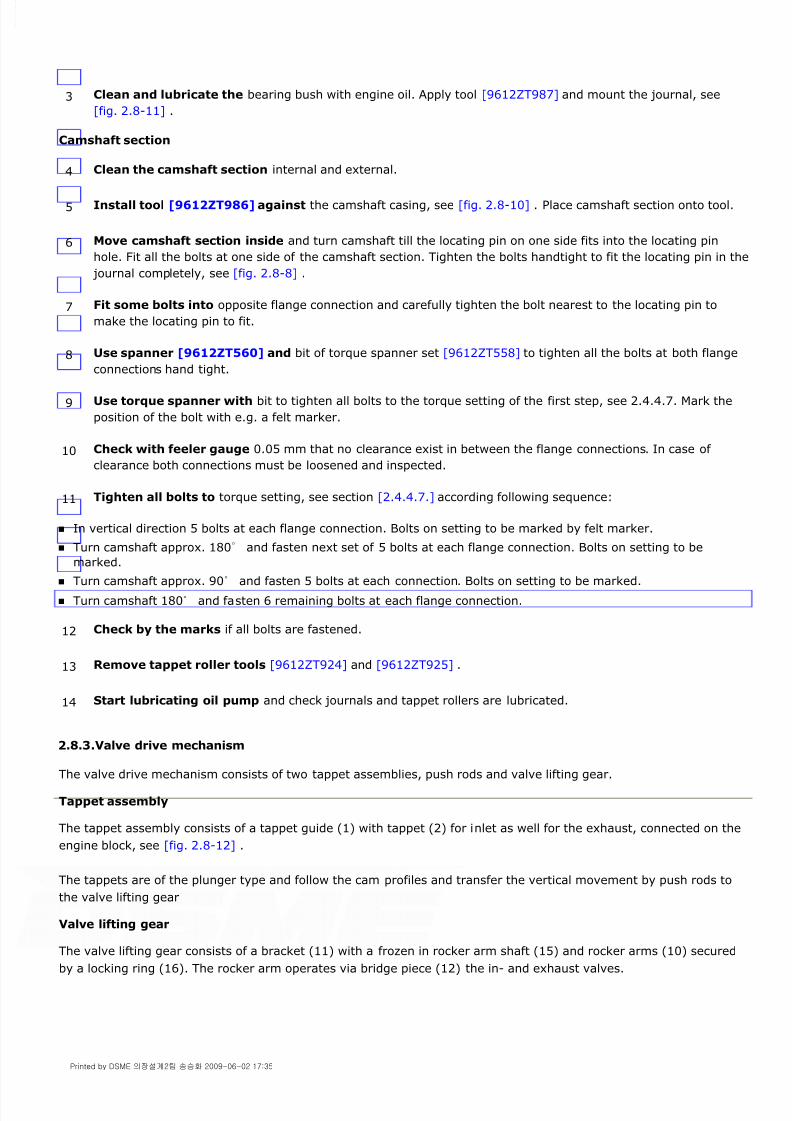
8/9/2019 W26 Instruction Manual
http://slidepdf.com/reader/full/w26-instruction-manual 278/304
P_0000045
Camshaft section
In vertical direction 5 bolts at each flange connection. Bolts on setting to be marked by felt marker.
Turn camshaft approx. 180° and fasten next set of 5 bolts at each flange connection. Bolts on setting to be
marked.
Turn camshaft approx. 90° and fasten 5 bolts at each connection. Bolts on setting to be marked.
Turn camshaft 180° and fasten 6 remaining bolts at each flange connection.
2.8.3.Valve drive mechanism
The valve drive mechanism consists of two tappet assemblies, push rods and valve lifting gear.
Tappet assembly
The tappet assembly consists of a tappet guide (1) with tappet (2) for inlet as well for the exhaust, connected on the
engine block, see [fig. 2.8-12] .
The tappets are of the plunger type and follow the cam profiles and transfer the vertical movement by push rods to
the valve lifting gear
Valve lifting gear
The valve lifting gear consists of a bracket (11) with a frozen in rocker arm shaft (15) and rocker arms (10) securedby a locking ring (16). The rocker arm operates via bridge piece (12) the in- and exhaust valves.
3 Clean and lubricate the bearing bush with engine oil. Apply tool [9612ZT987] and mount the journal, see
[fig. 2.8-11] .
4 Clean the camshaft section internal and external.
5 Install tool [9612ZT986] against the camshaft casing, see [fig. 2.8-10] . Place camshaft section onto tool.
6 Move camshaft section inside and turn camshaft till the locating pin on one side fits into the locating pin
hole. Fit all the bolts at one side of the camshaft section. Tighten the bolts handtight to fit the locating pin in the
journal completely, see [fig. 2.8-8] .
7 Fit some bolts into opposite flange connection and carefully tighten the bolt nearest to the locating pin to
make the locating pin to fit.
8 Use spanner [9612ZT560] and bit of torque spanner set [9612ZT558] to tighten all the bolts at both flange
connections hand tight.
9 Use torque spanner with bit to tighten all bolts to the torque setting of the first step, see 2.4.4.7. Mark the
position of the bolt with e.g. a felt marker.
10 Check with feeler gauge 0.05 mm that no clearance exist in between the flange connections. In case of
clearance both connections must be loosened and inspected.
11 Tighten all bolts to torque setting, see section [2.4.4.7.] according following sequence:
12 Check by the marks if all bolts are fastened.
13 Remove tappet roller tools [9612ZT924] and [9612ZT925] .
14 Start lubricating oil pump and check journals and tappet rollers are lubricated.
Printed by DSME 의장설계2팀 송승화 2009-06-02 17:35

8/9/2019 W26 Instruction Manual
http://slidepdf.com/reader/full/w26-instruction-manual 279/304
P_0000045
Figure 2.8-12: Tappet assembly and valve lifting gear
2.8.3.1.Removing valve drive mechanism
Note!
Mark parts properly before removing.
Bracket of valve lifting gear
Figure 2.8-13: Valve lifting gear
1 Remove cover from hot box and camshaft and remove cover from the cylinder head concerned.
2 Turn crankshaft in TDC at firing for cylinder concerned. Inlet and exhaust rollers are now on base circle (push
rods can rotate freely).
3 Remove bolts (13) and lift rocker arm bracket (11) with the use of eyebolt M16 (14) from cylinder head, see
[fig. 2.8-13] .
4 Remove push rods and push rod protecting sleeves.
Printed by DSME 의장설계2팀 송승화 2009-06-02 17:35

8/9/2019 W26 Instruction Manual
http://slidepdf.com/reader/full/w26-instruction-manual 280/304
P_0000045
Tappet assembly
Roller and shaft
2.8.3.2.Inspection of valve lifting gear
Rocker arm
Pivots
Figure 2.8-14: Valve lifting gear
Tappet assembly
Push rods
5 Place tool [9612ZT924] inside the 2 holes in tappet guide for inlet and exhaust to keep tappet roller lifted,
see [fig. 2.8-7] .
6 Disconnect tappet roller assemblies by removing bolts (3), see [fig. 2.8-12] .
7 Lift tappet roller assemblies out of cylinder block.
8 Take care for proper marking of all parts.
9 Remove tool [9612ZT924] and slide out tappet (2), push spring loaded locking pin (4) fully into shaft (5),
push shaft out off roller and remove roller (6) and bearing bush (7), see [fig. 2.8-12] .
1 Clean rocker arms and rocker arm shaft and measure for wear. After cleaning check oil channels. Refer to
chapter [2.4.] for clearance and wear limits.
2 Inspect running surfaces of pivoting points (18) in rocker arms (10) and from valve adjuster (17), see
[fig. 2.8-14] .
3 Clean and inspect all parts of tappet assembly for wear. Check if oil channels are open.
4 Measure diameters of bore and shaft. Replace parts outside the tolerance, see chapter
5 Clean and inspect running surfaces of the pivots.
6 Check if the push rods are straight.
Printed by DSME 의장설계2팀 송승화 2009-06-02 17:35

8/9/2019 W26 Instruction Manual
http://slidepdf.com/reader/full/w26-instruction-manual 281/304
P_0000045
2.8.3.3.Mounting valve drive mechanism
Note!
Take care, rollers are resting on base circle before mounting valve lifting gear.
2.8.4.Actuator drive
The actuator is driven by a separate drive unit with helical gear wheels (1) and (2). The drive unit is driven by the
camshaft gear wheel. The actuator is mounted on the drive unit and connected to the drive shaft through a serrated
connection (3).
Figure 2.8-15: Actuator drive
Pressurized oil is supplied through drillings in the drive unit for lubrication of the the bearings, the helical gear wheels
and the gear wheel drive.
1 Lubricate parts of tappet assembly with clean engine oil.
2 Slide tappet roller shaft (5) together with tappet roller (6) and bearing bush (7) into tappet (2), observing
spring loaded pin (4) fits into the corresponding hole of the tappet roller, see [fig. 2.8-12] .
3 Check if lube oil channels in cylinder block are clean. Fit new O-rings (8) and (9) before mounting.
4 Fit tappet roller lifting tool [9612ZT924] , see [fig. 2.8-7] .
5 Place tappet assemblies in cylinder block and fit bolts (3). See [fig. 2.8-12] .
6 Remove tappet roller lifting tool [9612ZT924] .
7 Slide push rod protecting sleeves from top side down.
8 Insert both push rods.
9 Check if the contact faces of the valve lifting gear and the cylinder head are clean.
10 Align the pivot of valve adjuster (17) to the centre of the topside of the bridge pieces (12), see [fig. 2.8-13] ,
fit bolts (13) and tighten the bolts to the correct torque. See chapter [2.4.]
11 Check free movement of rocker arms.
12 Check and adjust valve clearances according chapter [2.7.] and check lubrication. Mount covers and hot box
shields.
Printed by DSME 의장설계2팀 송승화 2009-06-02 17:35

8/9/2019 W26 Instruction Manual
http://slidepdf.com/reader/full/w26-instruction-manual 282/304
P_0000045
Maintenance
Actuator drive maintenance exists mainly of inspection of:
Warning!
If helical gear wheels are damaged, both gear wheels have to be renewed as a set.
Special tools are necessary to adjust the gearwheels.
1 Radial and axial clearances of bearings. See chapter
2 Backlash and condition of gear wheels.
3 Oil supply to bearings and gear wheels.
4 Condition of serrations of actuator drive shaft and coupling sleeve.
Printed by DSME 의장설계2팀 송승화 2009-06-02 17:35

8/9/2019 W26 Instruction Manual
http://slidepdf.com/reader/full/w26-instruction-manual 283/304
P_0000045
2.9.1.High Pressure (HP) fuel pump
Each cylinder has his own HP fuel pump (1), see [fig. 2.9-1] , which is connected by a shielded HP line (2) to the
injector.
The fuel pumps are of the mono-element and flow through type to ensure good performance. The pumps are
completely sealed from the crankcase preventing fuel contamination.
The fuel injection equipment and system piping are located in a hot box providing maximum reliability and safety. The
fuel oil supply and return manifolds are integrated in the HP fuel pump brackets (4).
Through line (7) lubricating oil is supplied for cooling of the injector.
Each HP fuel pump is provided with an air operated stop cylinder (3) which will bring the fuel rack to zero position
after control air is admitted .
Figure 2.9-1: HP fuel pump
Note!
For maintenance background information, safety aspects, intervals, tolerances, inspections, tools and torque spanner
instructions, see chapter [2.4.]
2.9.1.1.Removing HP fuel pump
Before removing the HP fuel pump take care the tappet roller (16) is resting on the base circle of the fuel cam (17),
see [fig. 2.9-7] .
2.9.Injection System 2.9-PAAE062665-00
1 Close the fuel supply to the engine.
2 Drain engine fuel system, see section
3 Remove fuel drain line (5).
Printed by DSME 의장설계2팀 송승화 2009-06-02 17:36

8/9/2019 W26 Instruction Manual
http://slidepdf.com/reader/full/w26-instruction-manual 284/304
P_0000045
Note!
The connecting pipe and HP fuel pipe must not be rotated with or against each other. Take care the locking plate
remains tight.
Figure 2.9-2: Fuel rack connection to common fuel control rod
Note!
Carefully lift the HP fuel pump in centre line direction to avoid clamping of push rod top (15) in fuel pump bottom
section, see [fig. 2.9-7] . Cover immediately all openings with tape or plugs to avoid dirt admission.
2.9.1.2.HP fuel pump disassembling
Note!
HP fuel pump parts should be kept matched during overhaul.
Note!
Plunger (7) is spring loaded. See [fig. 2.9-3]
4 To remove the HP fuel pipe (2), see section
5 Remove the air line (6) to stop cylinder (3).
6 Disconnect fuel rack (8) from the common fuel control rod (9) by removing nut (10) and connecting bolt
(11), see [fig. 2.9-2] .
7 Disconnect HP fuel pump (1) by removing nuts (12), see [fig. 2.9-1] .
8 Turn an eye bolt M12 into cover (9) and lift the HP fuel pump from the engine. See
1Before dismantling clean the pump externally.
2 Place the pump up side down.
3 Before mounting tool [9612ZT971] turn the disc nut (1) half way down on pivot (2). See [fig. 2.9-3] .
4 Mount tool [9612ZT971] with bolts (4)
5 Move pivot (2) down by turning the disc nut (1) with hook spanner [9612ZT442] till circlip (3) is free and the
remove the circlip.
6 Release spring (5) by turning nut (1) with hook spanner [9612ZT442] .
Printed by DSME 의장설계2팀 송승화 2009-06-02 17:36

8/9/2019 W26 Instruction Manual
http://slidepdf.com/reader/full/w26-instruction-manual 285/304
P_0000045
Figure 2.9-3: Disassembling HP fuel pump
Figure 2.9-4: HP fuel pump
7 Remove tool [9612ZT971] .
8 Remove spring disc (6), spring (5) and plunger (7) and turn pump into vertical position.
9 Remove bolts (8) and cover (9) and (10)), see [fig. 2.9-4] .
Printed by DSME 의장설계2팀 송승화 2009-06-02 17:36

8/9/2019 W26 Instruction Manual
http://slidepdf.com/reader/full/w26-instruction-manual 286/304
P_0000045
Figure 2.9-5: Removing barrel
Note!
Protect parts against rust and don't touch plunger element surfaces with bare fingers.
Keep pump element and pump barrel always matched as a pair.
2.9.1.3.HP fuel pump maintenance and inspection
Maintenance
Inspect fuel pump according maintenance intervals in chapter [2.4.] or earlier if performance requires.
Inspection
Note!
The barrel and the plunger of the fuel pump are matched and machined to each other. Barrel and plunger may
therefore not be exchanged with another barrel or plunger.
10 Remove main delivery valve (11) with spring (12) and constant pressure valve (13) with spring (14).
11 Put fuel rack (17) in zero position (0 mm), turn the pump up side down and remove control sleeve (23)
together with support ring (28).
12 To remove the fuel pump barrel (16), remove the bolts (15) and place the synthetic driver
[9612ZT225] against the bottom part of the barrel. With a few light hammer strokes the barrel comes free.),
see [fig. 2.9-5] .
13 To remove fuel rack (17) first disconnect stop cylinder (18) and piston (19). Take off plate (20) by removingbolt (21). Turn out guide plug (22) and pull out the fuel rack (17).
14 For inspection, flush plunger and barrel in clean fuel and keep plunger inserted in the barrel.
1 Check springs (12) and (14). Replace broken or damaged springs, see [fig. 2.9-4] .
2 Valves (11) and (13) should not be damaged. Valve (11) must slide easily in cylinder of barrel top. Valve (13)
must slide easily in valve (11).
3 Check sealing of cover (10) with barrel (16). Sealing edges should be free of damages.
4 Check fuel control sleeve (23) on free moving on outside of barrel (16). Check sleeve on fretting.
5 Check condition of barrel (16) and plunger (7). Replace barrel and plunger if necessary or according to the
maintenance intervals in chapter [2.4.]
6 Check if channel hole in barrel (16) at 'A' is open.
7 Check vertical fuel supply holes in pump body are clean and open.
8 Check erosion plugs (29) and renew if necessary.
9 Check fuel rack (17) on wear. Fuel rack wear introduces unstable pump deliveries.
Printed by DSME 의장설계2팀 송승화 2009-06-02 17:36

8/9/2019 W26 Instruction Manual
http://slidepdf.com/reader/full/w26-instruction-manual 287/304
P_0000045
2.9.1.4.Assembling the HP fuel pump
Note!
To prevent leakage always renew cover (10) and bolts (8), see [fig. 2.9-4]
Note!
The protruding vanes at both sides of the plunger lower side have to slide into the grooves of the control sleeve. To
make this easy going move at the same time the fuel rack to and fro.
Note!
Unless the HP fuel pump is immediately mounted on the engine, oil it well before storage. All openings in the pump
house should be well covered by plastic caps or tape.
2.9.1.5.HP fuel pump adjustment
The injection timing is determined by the moment the top of the plunger is in line with the top of the suction holes of
10 Check condition of spring (5)
1 Wash the components in absolutely clean diesel oil and lubricate the internal parts with clean engine oil.
During handling of the injection equipment components, keep your hands absolutely clean and greased with oil.
2 Reinstall spring (14), constant pressure valve (13), main delivery valve (11) and spring (12) into barrel
(16), see [fig. 2.9-4] .
3 Place a new cover (10), cover (9) and new bolts (8).
4 Apply new O-rings (24) and (25) with silicon grease on barrel.
5 Insert barrel in pump body (26). Position of barrel in pump body is determined by a dowel pin at top. Fit the
bolts (15).
6 Place pump body in a bracket to tighten bolts (15) in steps of 25Nm crosswise to required setting, see chapter
[2.4.] 4.8.
7 Tighten bolts (8) in steps of 10Nm crosswise to required setting, see section [2.4.4.8.] and check if top side
of barrel (16) and cover (9) are parallel ( tolerance // 0.3 mm ).
8 Release and retighten bolts (8) in one turn and one by one to the required setting.
9 Turn fuel pump up side down. Oil and insert fuel rack (17). Avoid sliding out of rack by fitting guide plug (22).
10 Oil and insert the fuel control sleeve (23) with the fuel rack in the zero position (0 mm). The control sleeve isat the serration provided with a pin (27). This pin has to fit into a recess of the fuel rack.
11 Move the fuel rack in mid position and place support ring (28).
12 After oiling of the plunger insert the plunger (7), the spring (5) and hook the spring disc (6) to the plunger.
13 Use tool [9612ZT971] to compress spring (5) and fit circlip (3), see [fig. 2.9-3] .
14 Release slowly the spring compression, remove the tool and check if the fuel rack moves easily in the pump
housing.
15 Mount stop cylinder to fuel rack and test working of stop cylinder with service air.
16 Check if the position of the stop block corresponds with the value mentioned in the testbed protocol.
Printed by DSME 의장설계2팀 송승화 2009-06-02 17:36

8/9/2019 W26 Instruction Manual
http://slidepdf.com/reader/full/w26-instruction-manual 288/304
P_0000045
the plunger housing
The timing may deviate due to manufacturing tolerances in pumps, cams and drive. To obtain the best possible
performance of the engine it is important that the injection timing is in accordance with the test bed protocol. See test
records.
Note!
Checking of the injection timing is always necessary after major components have been replaced, e.g. HP fuel pump
element, pump drive, camshaft section or some maintenance has been done on gears, especially to the intermediate
gear.
Checking the fuel pump drive
Checking the fuel injection timing
1 Remove the HP fuel pump. See section
2 Make sure the HP fuel pump bracket is properly mounted and no clearance exists between bracket and engine
block.
3 Remove the camshaft cover and check if the fuel cam roller (16) rests on the base circle of the cam (17), see
[fig. 2.9-6] .
4 Push the push rod (15) completely down and measure distance "X"
The top of push rod (15) is lower than the upper surface of the HP fuel pump bracket (4).
5 Check distance "X", see section [2.4.5.] [fig. 2.4-40] .
6 If distance "X" is out of range, see section [2.9.2.4.] and section
7 Starting point is that measurement "X" is within tolerance and the tappet roller (16) rests on the base circle
of the fuel cam (17).
8Place dial gauge [9622DT275] according [fig. 2.9-6] on top of the fuel pump bracket (4) with the contact
point of the dial gauge on top of the push rod (15) and set dial gauge at zero.
9 Turn the crankshaft in direction of rotation till the mark on the flywheel indicates the injection moment
mentioned in the test bed protocol.
10 Dial gauge reading should indicate a lift of the push rod of 4.5 mm with a tolerance of ±0.1 mm. (This is the
point where the effective pressure stroke of the fuel pump starts).
Printed by DSME 의장설계2팀 송승화 2009-06-02 17:36
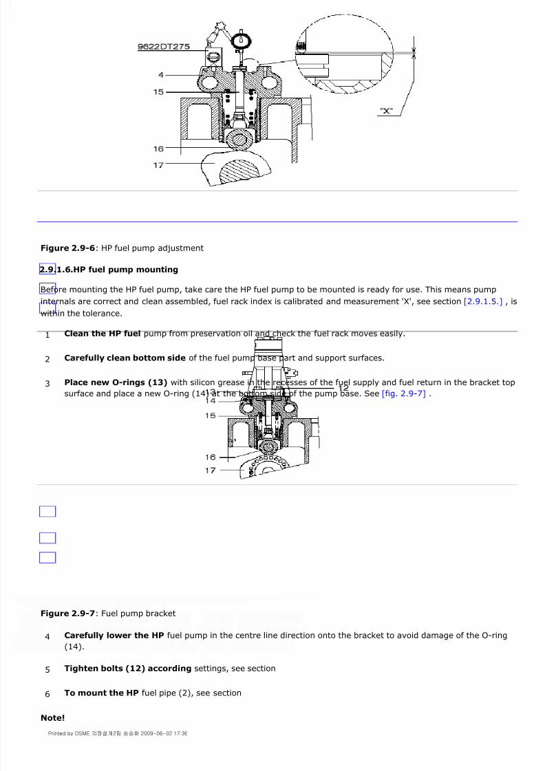
8/9/2019 W26 Instruction Manual
http://slidepdf.com/reader/full/w26-instruction-manual 289/304
P_0000045
Figure 2.9-6: HP fuel pump adjustment
2.9.1.6.HP fuel pump mounting
Before mounting the HP fuel pump, take care the HP fuel pump to be mounted is ready for use. This means pump
internals are correct and clean assembled, fuel rack index is calibrated and measurement 'X', see section [2.9.1.5.] , is
within the tolerance.
Figure 2.9-7: Fuel pump bracket
Note!
1 Clean the HP fuel pump from preservation oil and check the fuel rack moves easily.
2 Carefully clean bottom side of the fuel pump base part and support surfaces.
3 Place new O-rings (13) with silicon grease in the recesses of the fuel supply and fuel return in the bracket top
surface and place a new O-ring (14) at the bottom side of the pump base. See [fig. 2.9-7] .
4 Carefully lower the HP fuel pump in the centre line direction onto the bracket to avoid damage of the O-ring
(14).
5 Tighten bolts (12) according settings, see section
6 To mount the HP fuel pipe (2), see section
Printed by DSME 의장설계2팀 송승화 2009-06-02 17:36

8/9/2019 W26 Instruction Manual
http://slidepdf.com/reader/full/w26-instruction-manual 290/304
P_0000045
The connecting pipe and HP fuel pipe must not be rotated with or against each other.
All the fuel pump racks follow the rod movement.
All the fuel pump rack readings are equal. The maximum allowable difference between the fuel pump racks is 1 mm.
2.9.2.Fuel pump bracket
The fuel pump brackets (4) are each interconnected by pipe sections (18) for the fuel supply (19) to and return (20)
from the pump (1).
In top of the brackets two small drillings (21), each surrounded by an O-ring (13), are connected to the internal fuel
supply (19) and return (20) of the fuel pumps. These drillings are restrictions to damp the chock pulses generatedafter the pump plunger releases the compressed HP fuel. The fuel pump bracket (4) is also a guidance for the fuel
pump tappet (37) and push rod (15).
The fuel pump bracket (4), near end cover (22), is provided with an internal pipe section (23) see [fig. 2.9-8] .
Figure 2.9-8: Fuel pump bracket
2.9.2.1.Removing fuel pump bracket
7 Mount fuel drain line (5) and air line (6) to the stop cylinder (3), see
8 Connect fuel rack to common fuel control rod. See [fig. 2.9-2] .
9 Rotate the common fuel control rod and check if :
10 Open the fuel supply and discharge lines to the engine and circulate the fuel for some time to vent the
system. Turn simultaneously the crankshaft.
1 Close the fuel supply to the engine.
Printed by DSME 의장설계2팀 송승화 2009-06-02 17:36

8/9/2019 W26 Instruction Manual
http://slidepdf.com/reader/full/w26-instruction-manual 291/304
P_0000045
Note!
When the fuel pump bracket (4) next to the end cover (22) has to be removed, first remove the adjacent fuel pump
bracket with the pipe sections (18). Next shift the internal pipe sections (23) of the bracket out of the end cover (22).
Figure 2.9-9: Fuel pump bracket
For inspection of the fuel pump bracket see section [2.9.2.5.]
2 Drain the engine fuel system, see section [1.1.5.] .
3 Remove HP fuel pump, see section
4 Disconnect the lube oil line (7) from the pump bracket to the cylinder head, see section [2.9.1.]
5 Slide circlip (24) of the pipe sections concerned backwards, see [fig. 2.9-8] .
6 Slide the pipe sections concerned into the brackets, see [fig. 2.9-8] .
7 Turn camshaft till tappet roller (16) is on top of fuel cam (17) and fit locking tool [9612ZT925] . See
[fig. 2.9-9] .
8 Turn camshaft till tappet roller (16) is free from fuel cam (17). See [fig. 2.9-7] .
9 Remove positioning bolt (25), see [fig. 2.9-9] .
10 Fit lifting tool [9612ZT961] to the fuel pump bracket, see [fig. 2.9-10] .
11 Lift fuel pump bracket out of engine block.
12 Cover all holes against dirt penetration.
Printed by DSME 의장설계2팀 송승화 2009-06-02 17:36
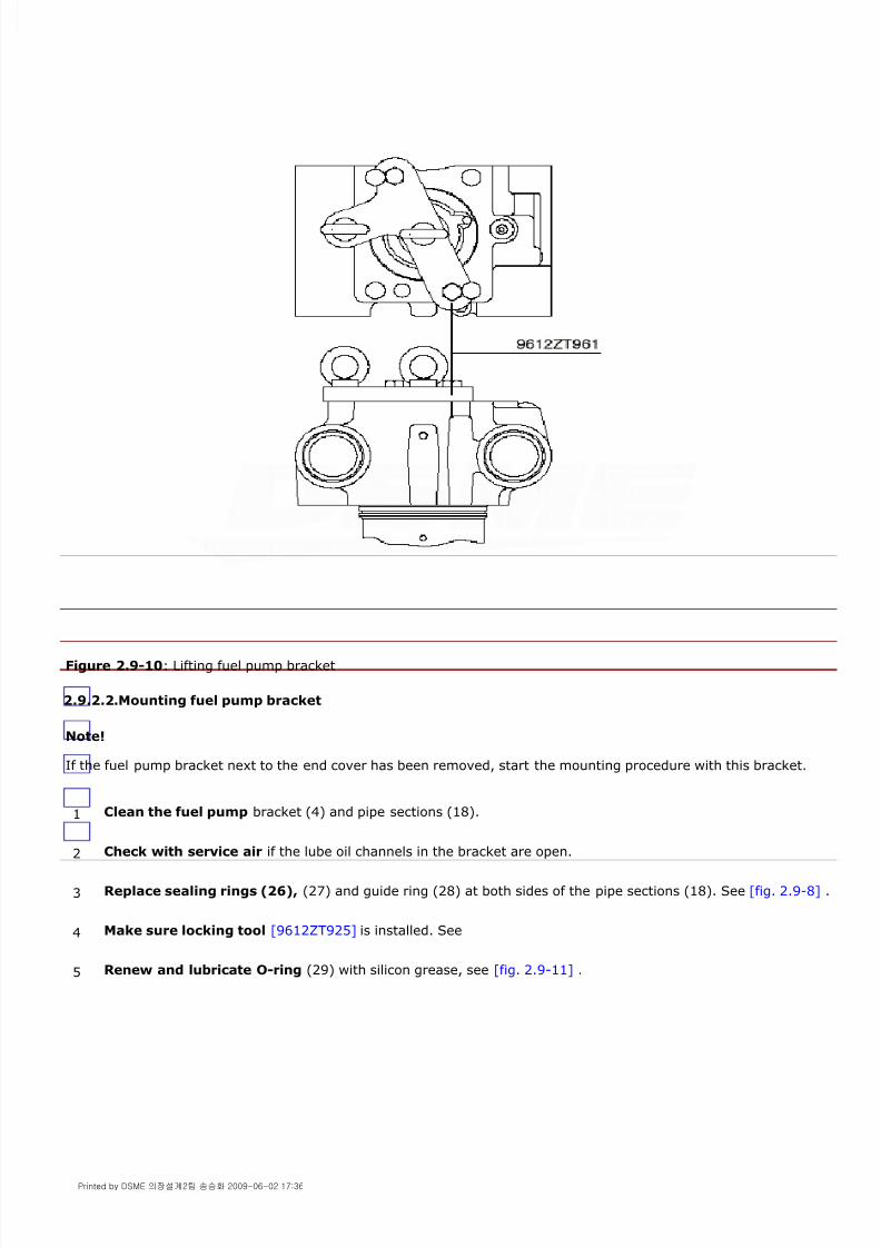
8/9/2019 W26 Instruction Manual
http://slidepdf.com/reader/full/w26-instruction-manual 292/304
P_0000045
Figure 2.9-10: Lifting fuel pump bracket
2.9.2.2.Mounting fuel pump bracket
Note!
If the fuel pump bracket next to the end cover has been removed, start the mounting procedure with this bracket.
1 Clean the fuel pump bracket (4) and pipe sections (18).
2 Check with service air if the lube oil channels in the bracket are open.
3 Replace sealing rings (26), (27) and guide ring (28) at both sides of the pipe sections (18). See [fig. 2.9-8] .
4 Make sure locking tool [9612ZT925] is installed. See
5 Renew and lubricate O-ring (29) with silicon grease, see [fig. 2.9-11] .
Printed by DSME 의장설계2팀 송승화 2009-06-02 17:36

8/9/2019 W26 Instruction Manual
http://slidepdf.com/reader/full/w26-instruction-manual 293/304
P_0000045
Figure 2.9-11: Fuel pump bracket
6 Insert the two pipe sections (18), provided with circlip (24), not yet fitted in the groove, into the bracket (4),
see [fig. 2.9-8] .
7 Turn the camshaft till the tappet roller (16) rests on the base circle of the fuel cam (17). See [fig. 2.9-11] .
8 Clean bottom side fuel pump bracket and and top side of cylinder block. Take care of presence of dowel pin
(30). Renew the O-ring between engine block and bracket and lower bracket onto the clean engine block, see[fig. 2.9-9] .
9 Fit the positioning bolt (25), see [fig. 2.9-9] and set the bolt to the right torque, see section [2.4.4.8.] .
10 Turn fuel cam into top, remove locking tool [9612ZT925] .
11 Turn camshaft till tappet roller (16) rests on the base circle of the fuel cam (17), see [fig. 2.9-11] .
12 Make sure the HP fuel pump bracket is properly mounted and no clearance exists between bracket and engine
block.
13 Check the sealing set (31+32) of the fuel pump push rod. Renew if necessary, see section [2.9.2.3.] for the
procedure.
14 Push the push rod (15) completely down and measure distance "X"
Top of push rod (15) is lower than upper surface of bracket (4), see [fig. 2.9-6] .
15 Check distance "X", see section [2.4.5.] [fig. 2.4-40] .
16 If distance "X" is out of range, see section [2.9.2.4.] and section
17 Slide pipe sections in place and lock pipe sections with circlip (24), see [fig. 2.9-8] .
18 Mount the lube oil line (7) from the pump bracket to the cylinder head, see section [2.9.1.]
19 Mount the HP fuel pump, see section
Printed by DSME 의장설계2팀 송승화 2009-06-02 17:36

8/9/2019 W26 Instruction Manual
http://slidepdf.com/reader/full/w26-instruction-manual 294/304
P_0000045
Warning!
Do not run the engine with tool [9612ZT925] mounted.
2.9.2.3.Renewal sealing set push rod
To keep the fuel pump bottom side separated from the camshaft space the fuel pump push rod passage is sealed by a
sealing set consisting of an O-ring (31) and a scraper ring (32), see [fig. 2.9-11] .
Mounting push rod sealing set
20 Open fuel supply, circulate fuel over the engine and check for fuel leaks.
1 Clean and inspect the sealing ring recess.
2 Lubricate the O-rings (31) of the sealing set with silicon grease and insert them in the recess, see
[fig. 2.9-11] .
3 Fit the scraper ring (32) onto penetrator (33) and lubricate the scraper ring with silicon grease. Take care ofthe correct scraper ring position on penetrator, see [fig. 2.9-12] .
4 Place conductor (34) firm onto the bracket top side and slide the penetrator into the conductor till the end.
The compressed scraper ring will expand into the recess.
5 Retract the penetrator (33).
6 Provide the expander (35) with silicon grease and slide the expander through the mounted scraper ring (32)
to widen the diameter till normal.
7 After the scraper ring is mounted place plug (36) into the penetrator (33) and restore the tool set in the
toolbox.
8 Install the fuel pump push rod (15).
Printed by DSME 의장설계2팀 송승화 2009-06-02 17:36

8/9/2019 W26 Instruction Manual
http://slidepdf.com/reader/full/w26-instruction-manual 295/304
P_0000045
Figure 2.9-12: Mounting push rod seal set
2.9.2.4.Inspection of fuel pump push rod
The connection between the fuel pump tappet (37) and fuel pump plunger is made by the fuel pump push rod (15),
see [fig. 2.9-11] .
Due to machining tolerances in components between the fuel pump tappet and the fuel pump plunger, the push rod
lengths vary from one to another.
During maintenance the push rods should be provided with the cylinder unit number and not be interchanged. A new
push rod should be machined to the correct length at the smallest end.
Note!
Fuel pump push rods are precision ground to the exact length for each individual pump bracket. Do not interchange
these push rods.
For determination of length of fuel pump push rod (15) take care that the tappet roller (16) rests on the base circle.
Take the push rod out and place depth gauge [9612ZT547] , see [fig. 2.9-13] . The depth gauge reading minus 1 mm
gives the exact length of push rod to be installed. If 'X' is not within tolerance inspect the concerned parts for wear.
For tolerance see section [2.4.5,] [fig. 2.4-40] .
Printed by DSME 의장설계2팀 송승화 2009-06-02 17:36

8/9/2019 W26 Instruction Manual
http://slidepdf.com/reader/full/w26-instruction-manual 296/304
P_0000045
Figure 2.9-13: Depth gauge for push rod
2.9.2.5.Inspection of fuel pump tappet
Figure 2.9-14: Assembling tool fuel pump bracket
1 Remove the fuel pump bracket from the engine according to
section [2.9.2.1.]
2 Remove the push rod out of the fuel pump bracket.
3 Place the bracket up side down on the base plate of tool [9612ZT960] , see [fig. 2.9-14] and connect the jack[9612ZT341] of tool [9612ZT960] to the hydraulic pump [9612ZT955] .
4 Compress the fuel pump tappet spring and remove the locking tool [9612ZT925] , see [fig. 2.9-9] .
5 Slowly release the jack pressure till the fuel pump tappet spring is fully expanded.
6 The fuel pump tappet assembly can be taken out of the bracket.
7 Press locking pin (38) to slide shaft (39) out of the fuel pump tappet and the tappet roller. See [fig. 2.9-14] .
Printed by DSME 의장설계2팀 송승화 2009-06-02 17:36

8/9/2019 W26 Instruction Manual
http://slidepdf.com/reader/full/w26-instruction-manual 297/304
P_0000045
2.9.3.Fuel injector
HP fuel (1) enters the injector holder sideways delivered through the connecting piece, see [fig. 2.9-15] .
Spill fuel (4), passing the injector needle, escapes along the holder and the connecting piece through a hole in the
cylinder head at (4).
Leaking combustion gases, passing the sealing between the sealing surface in the cylinder head and the injector tip,
will escape together with the spill fuel at (5).
The injector tip is cooled by lubricating oil supplied by the engine lubrication system. The oil enters the injector at (2)
and after cooling the injector tip it leaves at (3) at top of the injector. Afterwards the oil runs down to the crankcase.
An O-ring is fitted around the injector to avoid lube oil leaking downwards the injector holder.
Figure 2.9-15: Cylinder head with injector
2.9.3.1.Fuel injector maintenance
Follow the injector maintenance schedule or overhaul the injectors when engine performance gives indication of poor
injection (large deviation from normal exhaust gas temperature etc.). See chapter [2.4.]
2.9.3.2.Fuel injector removing
8 Clean and inspect all parts for wear.
9 For assembling of the fuel pump bracket, assemble in reversed way. Do not forget to replace spring discs
(40) during assembling of bracket unit.
10 Place the locking tool [9612ZT925] , see [fig. 2.9-9] .
1 Remove the cylinder head cover and the Hot-Box cover.
2 To remove the HP fuel pipe (2) and the HP connecting pipe (3), see section
Printed by DSME 의장설계2팀 송승화 2009-06-02 17:36

8/9/2019 W26 Instruction Manual
http://slidepdf.com/reader/full/w26-instruction-manual 298/304
P_0000045
Note!
The connecting pipe and HP fuel pipe must not be rotated with or against each other. Take care the locking plate
remains tight.
Figure 2.9-16: Fuel injector in cylinder head
Warning!
Don't start engine lubrication when an injector is removed from cylinder head. Lubricating oil may uncontrolled enter
top of piston.
Note!
Check if the sealing washer (20) is present on the injector tip (15), if not remove it from the cylinder head. See
fig .2.9 - 18 .
3 Remove nuts (6), distance sleeves (7) and gland (8), see [fig. 2.9-16] .
4 Extract injector with tool [9612ZT178] or with tool [9612ZT931] in case the injector is too tight in the
injector sleeve.
Printed by DSME 의장설계2팀 송승화 2009-06-02 17:36
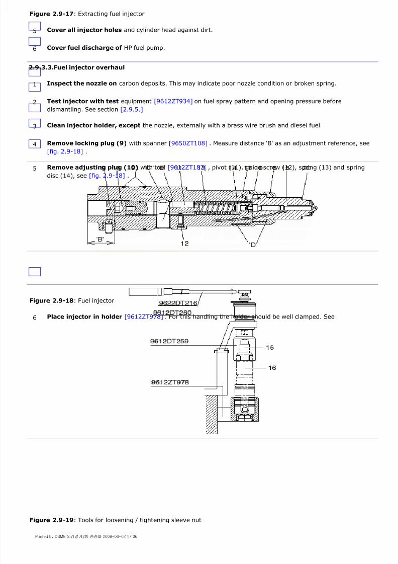
8/9/2019 W26 Instruction Manual
http://slidepdf.com/reader/full/w26-instruction-manual 299/304
P_0000045
Figure 2.9-17: Extracting fuel injector
2.9.3.3.Fuel injector overhaul
Figure 2.9-18: Fuel injector
Figure 2.9-19: Tools for loosening / tightening sleeve nut
5 Cover all injector holes and cylinder head against dirt.
6 Cover fuel discharge of HP fuel pump.
1 Inspect the nozzle on carbon deposits. This may indicate poor nozzle condition or broken spring.
2 Test injector with test equipment [9612ZT934] on fuel spray pattern and opening pressure before
dismantling. See section [2.9.5.]
3 Clean injector holder, except the nozzle, externally with a brass wire brush and diesel fuel.
4 Remove locking plug (9) with spanner [9650ZT108] . Measure distance 'B' as an adjustment reference, see
[fig. 2.9-18] .
5 Remove adjusting plug (10) with tool [9612ZT187] , pivot (11), guide screw (12), spring (13) and spring
disc (14), see [fig. 2.9-18] .
6 Place injector in holder [9612ZT978] . For this handling the holder should be well clamped. See
Printed by DSME 의장설계2팀 송승화 2009-06-02 17:36

8/9/2019 W26 Instruction Manual
http://slidepdf.com/reader/full/w26-instruction-manual 300/304
P_0000045
Note!
Carbon deposits can make it difficult to slide injector tip out off sleeve nut. In such a case place injector tip with
sleeve nut on a soft support and knock injector tip out by using a piece of pipe.
Never knock directly on injector tip, see [fig. 2.9-20] .
Figure 2.9-20: Separating injector tip from sleeve nut
Needle moves freely over full length.
Needle moves freely within normal lifting range.
Needle is not sticking.
Injector tip is free from signs of cavitation.
Spray holes of injector tip are open.
Maximum needle lift 'A', see chapter [2.4.] 5. Replace injector tip if 'A' is out of limit.
Cooling oil passage is free and clean.
Sealing faces are clean between injector tip (15) and injector holder (17).
Sealing face 'C' must be clean and undamaged. See [fig. 2.9-18] . Cooling oil supply and discharge holes are free and clean.
Fuel spill drain is free and clean.
Condition O-ring grooves
Note!
Apply Molykote G-rapid plus or Never-Seez Regular grade NS 42 B between contact surfaces 'D' of sleeve nut and
injector tip and on the thread. See [fig. 2.9-18] .
7 Remove injector tip (15) from holder by turning off sleeve nut (16) with socket spanner
[9612DT259] multiplier [9612DT260] and spanner [9622DT216] .
8 Use a chemical carbon dissolving solution to clean injector tips. If such is not available immerse components
in clean fuel oil, white spirit or similar to soak carbon. Clean parts carefully. Don't apply steel wire brushes or
hard abrasive tools. Clean injector spray holes with needles provided for this purpose. Keep injector tips and
needles matched.
9 Check following of injector tip and needle:
10 Immerse parts in clean fuel oil or in a calibration fluid before inserting needle in injector tip.
11 Check following of injector holders:
12 Check condition of spring and spring disc.
13 Place injector tip (15) over both dowel pins (19) onto injector holder. .
14 Turn on the sleeve nut (16) and tighten the nut to the correct torque using socket spanner [9612DT259] and
torque spanner [9622DT216] in combination with multiplier [9612DT260] see [fig. 2.9-19] . For torque settings
see section [2.4.4.8.]
Printed by DSME 의장설계2팀 송승화 2009-06-02 17:36

8/9/2019 W26 Instruction Manual
http://slidepdf.com/reader/full/w26-instruction-manual 301/304
P_0000045
Note!
Calculate torque spanner reading according the conversion factor of the multiplier and see for torque spanner
instructions section [2.4.3.]
2.9.3.4.Fuel injector mounting
Before mounting an injector check the injector condition with test equipment [9612ZT934] on opening pressure, spray
pattern and nozzle needle leak.
Note!
The connecting pipe and HP fuel pipe must not be rotated with or against each other.
2.9.4.HP fuel pipe
The connection between HP fuel pump (1) and fuel injector (4) consists of a shielded HP fuel pipe (2) and a connecting
pipe (3) mounted in the fuel injector (4), see [fig. 2.9-21] .
15 Insert spring disc (14), spring (13), guide screw (12), pivot (11) and turn in adjusting plug (10) to distance
'B'.
16 Check the injector condition with test equipment [9612ZT934] . See section
17 After adjusting the opening pressure, turn in the locking plug (9) with tool [9650ZT108] , tighten the plug to
the correct torque see section [2.4.4.8.]
1 Remove the old sealing washer (20) if still present (see [fig. 2.9-18] ), from the sealing surface in the
cylinder head and clean the injector sleeve.
2 Check the sealing surface in the cylinder head is clean. Apply a fine lapping compound on tool
[9612ZT962] in case of irregularities.
3 Place a new sealing washer (20), see [fig. 2.9-18] .
4 Fit new O-rings (21) with silicon grease onto the injector body and place the injector into the cylinder head.
See [fig. 2.9-18] .
5 Place the injector gland (8) and distance sleeves (7). Fasten the injector nuts (6) by hand and loosen half a
turn. See [fig. 2.9-16]
6 Mount the HP connecting pipe (3), see section
7 Fasten nuts (6) in steps of 10 Nm by torque spanner up till final setting, see section
8 Tighten locking plate (5) see [fig. 2.9-21] .
9 Mount the HP fuel pipe (2), see section
10 Start engine lubrication and observe lubricating oil escaping at the top of the injector.
Printed by DSME 의장설계2팀 송승화 2009-06-02 17:36
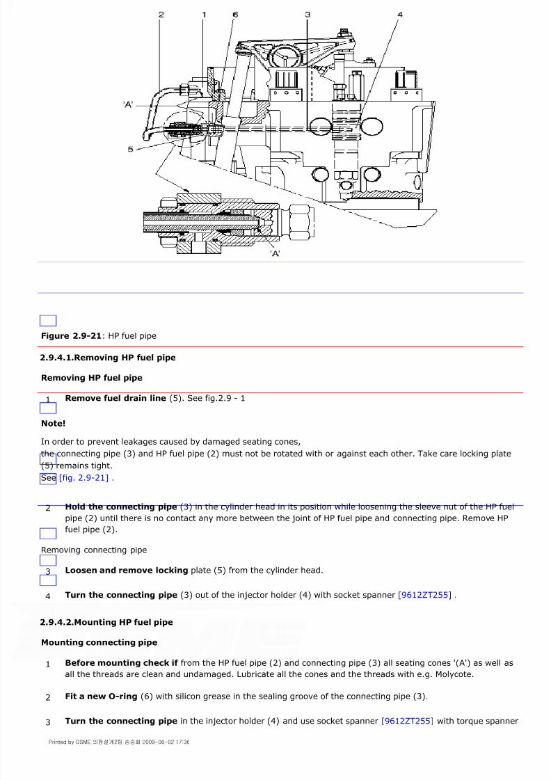
8/9/2019 W26 Instruction Manual
http://slidepdf.com/reader/full/w26-instruction-manual 302/304
P_0000045
Figure 2.9-21: HP fuel pipe
2.9.4.1.Removing HP fuel pipe
Removing HP fuel pipe
Note!
In order to prevent leakages caused by damaged seating cones,
the connecting pipe (3) and HP fuel pipe (2) must not be rotated with or against each other. Take care locking plate
(5) remains tight.
See [fig. 2.9-21] .
Removing connecting pipe
2.9.4.2.Mounting HP fuel pipe
Mounting connecting pipe
1 Remove fuel drain line (5). See fig.2.9 - 1
2 Hold the connecting pipe (3) in the cylinder head in its position while loosening the sleeve nut of the HP fuel
pipe (2) until there is no contact any more between the joint of HP fuel pipe and connecting pipe. Remove HP
fuel pipe (2).
3 Loosen and remove locking plate (5) from the cylinder head.
4 Turn the connecting pipe (3) out of the injector holder (4) with socket spanner [9612ZT255] .
1 Before mounting check if from the HP fuel pipe (2) and connecting pipe (3) all seating cones '(A') as well asall the threads are clean and undamaged. Lubricate all the cones and the threads with e.g. Molycote.
2 Fit a new O-ring (6) with silicon grease in the sealing groove of the connecting pipe (3).
3 Turn the connecting pipe in the injector holder (4) and use socket spanner [9612ZT255] with torque spanner
Printed by DSME 의장설계2팀 송승화 2009-06-02 17:36

8/9/2019 W26 Instruction Manual
http://slidepdf.com/reader/full/w26-instruction-manual 303/304
P_0000045
Mounting HP fuel pipe
Note!
In order to prevent leakages caused by damaged seating cones,
the connecting pipe (3) and HP fuel pipe (2) must not be rotated with or against each other. See [fig. 2.9-21] .
2.9.5.Testing of fuel injectors
Warning!
Be careful in testing fuel injectors. Fuel jets are powerful and will penetrate skin and underlying skin layers and blood.
Such an accident calls for direct specialistic treatment. Should this aid not be available disinfect affected part of body.
However, it remains necessary to consult a specialist.
Testing the opening pressure
Figure 2.9-22: Testing device fuel injectors
[9622DT215] to tighten the connecting pipe at correct torque according section [2.4.4.8.]
4 Place locking plate (5), do not tighten the bolts.
If necessary first tighten the injector nuts, see section
5 Tighten locking plate (5) to the cylinder head.
6 Set the HP fuel pipe simultaneously into the appropriate position to the pump and to the connecting piece
connection. Turn both sleeve nuts manually onto the connections.
7 Tighten the sleeve nuts using crow foot spanner [9612ZT331] and torque spanner [9622DT215] till torque
setting, mentioned in section [2.4.4.8.]
8 Mount fuel drain line (5). See fig.2.9 - 1
1 Fill the pump reservoir with absolutely calibration fluid even if a filter is mounted in the reservoir.
2 Connect the injector to the test equipment.
3 Before final tightening of the connecting line between the pump and the injector fill the connecting line with
fuel and vent the air by a few pump strokes.
4 Tighten the connection.
5 Increase the pump pressure slowly and watch the manometer pressure on fuel spraying commencement.
The opening pressure should be accurate within 10 bar. For openings pressure see section [2.4.5.1.]
Printed by DSME 의장설계2팀 송승화 2009-06-02 17:36

8/9/2019 W26 Instruction Manual
http://slidepdf.com/reader/full/w26-instruction-manual 304/304
P_0000045
Adjusting the opening pressure