w controller plant
TRANSCRIPT

��
�
�
�
�R Y
Controller Plant
D (s) G (s)
Sensor
H (s)
U
W
�
�
�V
Figure 5.1 Basic closed loop block diagram
©2002 Prentice Hall, Inc. Gene F. Franklin, J. David Powell, Abbas Emami-NaeiniFeedback Control of Dynamic Systems, 4e

�2 �1
Real axis
0 1 2�1.5
�1
�0.5
0
0.5
1
1.5
Imag
axi
s
u � sin�1 z � 30�
Figure 5.2 Root locus for L(s) = 1/[s(s + 1)]
©2002 Prentice Hall, Inc. Gene F. Franklin, J. David Powell, Abbas Emami-NaeiniFeedback Control of Dynamic Systems, 4e

�2 �1
Real axis
0 1 2�1.5
�1
�0.5
0
0.5
1
1.5
Imag
axi
s
Figure 5.3 Root locus vs. damping factor c for 1 + G(s) = 1 + 1/[s(s + c)] = 0
©2002 Prentice Hall, Inc. Gene F. Franklin, J. David Powell, Abbas Emami-NaeiniFeedback Control of Dynamic Systems, 4e

�2 �1
Real axis
0 1 2�3
�2
�1
0
1
2
3
Imag
axi
s
f2 � 0
f3
s0
c1
f4f1
Figure 5.4 Measuring the phase of Eq. (5.15)
©2002 Prentice Hall, Inc. Gene F. Franklin, J. David Powell, Abbas Emami-NaeiniFeedback Control of Dynamic Systems, 4e

�8 �2�4�6
Real axis
0 1 2�4
�2
2
4
Imag
axi
ss0
f3 � 0
f1
f2
Figure 5.5 Rule 2. The real-axis parts of the locus are to the left of an odd numberof poles and zeros.
©2002 Prentice Hall, Inc. Gene F. Franklin, J. David Powell, Abbas Emami-NaeiniFeedback Control of Dynamic Systems, 4e

�10 �5
Real axis
0 5�6
�4
�2
0
2
4
6
Imag
axi
s
Figure 5.6 The asymptotes are n − m radial lines from α at equal angles.
©2002 Prentice Hall, Inc. Gene F. Franklin, J. David Powell, Abbas Emami-NaeiniFeedback Control of Dynamic Systems, 4e

�10 �5
Real axis
0 5�6
�4
�2
0
2
4
6
Imag
axi
s
f2
Pole 1
Pole 3
f3
f1
Pole 2
s0
Figure 5.7 The departure and arrival angles are found by looking near a pole or zero.
©2002 Prentice Hall, Inc. Gene F. Franklin, J. David Powell, Abbas Emami-NaeiniFeedback Control of Dynamic Systems, 4e

�10 �5
Real axis
0 5�6
�4
�2
0
2
4
6
Imag
axi
s
jv crossing
Figure 5.8 A locus crosses the imaginary axis as determined by Routh’s criterion for stability.
©2002 Prentice Hall, Inc. Gene F. Franklin, J. David Powell, Abbas Emami-NaeiniFeedback Control of Dynamic Systems, 4e

�10 �5
Real axis
0 5�6
�4
�2
0
2
4
6
Imag
axi
s
Figure 5.9 Root locus for L(s) = 1/[s(s2 + 8s + 32)]
©2002 Prentice Hall, Inc. Gene F. Franklin, J. David Powell, Abbas Emami-NaeiniFeedback Control of Dynamic Systems, 4e

�5 0
Real axis
5 10�6
�4
�2
0
2
4
6
Imag
axi
s
Figure 5.10 Negative root locus corresponding to L(s) = (s − 6)/s(s2 + 4s + 13)
©2002 Prentice Hall, Inc. Gene F. Franklin, J. David Powell, Abbas Emami-NaeiniFeedback Control of Dynamic Systems, 4e

�6 �4
Real axis
�2 0 2�3
�2
�1
0
1
2
3
Imag
axi
s
Figure 5.11 Root locus for L(s) = G(s) = (s + 1)/s2
©2002 Prentice Hall, Inc. Gene F. Franklin, J. David Powell, Abbas Emami-NaeiniFeedback Control of Dynamic Systems, 4e

�6 �4
Real axis
�2 0 2�3
�2
�1
0
1
2
3
Imag
axi
s
Figure 5.12 Root locus for L(s) = (s + 1)/s2(s + 12)
©2002 Prentice Hall, Inc. Gene F. Franklin, J. David Powell, Abbas Emami-NaeiniFeedback Control of Dynamic Systems, 4e

�6 �4
Real axis
�2 0 2�3
�2
�1
0
1
2
3
Imag
axi
s
Figure 5.13 Root locus for L(s) = (s + 1)/s2(s + 4)
©2002 Prentice Hall, Inc. Gene F. Franklin, J. David Powell, Abbas Emami-NaeiniFeedback Control of Dynamic Systems, 4e

�6 �4
Real axis
�2 0 2�3
�2
�1
0
1
2
3
Imag
axi
s
Figure 5.14 Root locus for L(s) = (s + 1)/s2(s + 9)
©2002 Prentice Hall, Inc. Gene F. Franklin, J. David Powell, Abbas Emami-NaeiniFeedback Control of Dynamic Systems, 4e

�15 �10
Real axis
0�5 5�8
�6
�4
�2
0
2
4
6
8
Imag
axi
sf5
c1
c2
c3
f1
f2, f3
f4
Figure 5.15 Figure for computing a departure angle for
L(s) = s + 1s + 12
(s + 0.1)2 + 62
s2[(s + 0.1)2 + 6.62]
©2002 Prentice Hall, Inc. Gene F. Franklin, J. David Powell, Abbas Emami-NaeiniFeedback Control of Dynamic Systems, 4e

�15 �10
Real axis
0�5 5�8
�6
�4
�2
0
2
4
6
8
Imag
axi
s
Figure 5.16 Root locus for L(s) = s + 1s + 12
(s + 0.1)2 + 62
s2[(s + 0.1)2 + 6.62]
©2002 Prentice Hall, Inc. Gene F. Franklin, J. David Powell, Abbas Emami-NaeiniFeedback Control of Dynamic Systems, 4e

�15 �10
Real axis
0�5 5�8
�6
�4
�2
0
2
4
6
8
Imag
axi
sf5
c1
f1
f2, f3
f4
Figure 5.17 Figure to compute a departure angle for
L(s) = s + 1s + 12
1s2[(s + 0.1)2 + 6.62]
©2002 Prentice Hall, Inc. Gene F. Franklin, J. David Powell, Abbas Emami-NaeiniFeedback Control of Dynamic Systems, 4e

�15 �10
Real axis
0�5 5�8
�6
�4
�2
0
2
4
6
8
Imag
axi
s
Figure 5.18 Root locus for L(s) = s + 1s + 12
1s2[(s + 0.1)2 + 6.62]
©2002 Prentice Hall, Inc. Gene F. Franklin, J. David Powell, Abbas Emami-NaeiniFeedback Control of Dynamic Systems, 4e

�4 �2
Real axis
0 2 4�3
�2
�1
0
1
2
3
Imag
axi
s
f3
f1f2
f4
Figure 5.19 Figure to compute departure angle for L(s) = 1s(s + 2)[(s + 1)2 + 4]
©2002 Prentice Hall, Inc. Gene F. Franklin, J. David Powell, Abbas Emami-NaeiniFeedback Control of Dynamic Systems, 4e

�4 �2
Real axis
0 2 4�3
�2
�1
0
1
2
3
Imag
axi
s
Figure 5.20 Root locus for L(s) = 1s(s + 2)[(s + 1)2 + 4]
©2002 Prentice Hall, Inc. Gene F. Franklin, J. David Powell, Abbas Emami-NaeiniFeedback Control of Dynamic Systems, 4e

s0 � s2
s0 � s1
z � 0.5
z � 0.5
s0 � s3
�10 6420�2�4�6�8�6
�4
�2
0
2
4
6
Imag
e ax
is
Real axis
Figure 5.21 Root locus for L(s) = 1/{s[(s + 4)2 + 16]} showing calculations of gain K
©2002 Prentice Hall, Inc. Gene F. Franklin, J. David Powell, Abbas Emami-NaeiniFeedback Control of Dynamic Systems, 4e

��
�
R Y
Controller Plant
G (s)D(s)
U
Figure 5.22 Feedback system with compensation
©2002 Prentice Hall, Inc. Gene F. Franklin, J. David Powell, Abbas Emami-NaeiniFeedback Control of Dynamic Systems, 4e

Imag
e ax
is
Real axis
�6 210�1�2�3�4�5�3
�2
�1
0
1
2
3
Figure 5.23 Root loci for 1 + D(s)G(s) = 0, G(s) = 1/[s(s + 1)]: with compensationD(s) = K (solid lines) and with D(s) = K(s + 2) (dashed lines)
©2002 Prentice Hall, Inc. Gene F. Franklin, J. David Powell, Abbas Emami-NaeiniFeedback Control of Dynamic Systems, 4e

Imag
e ax
is
Real axis
�6 210�1�2�3�4�5�3
�2
�1
0
1
2
3
Lead pole at �20
Lead pole at �10
PD control
Figure 5.24 Root loci for three cases with G(s) = 1/[s(s + 1)]:(a) D(s) = (s + 2)/(s + 20); (b) D(s) = (s + 2)/(s + 10);
(c) D(s) = s + 2 (solid lines)
©2002 Prentice Hall, Inc. Gene F. Franklin, J. David Powell, Abbas Emami-NaeiniFeedback Control of Dynamic Systems, 4e

�14 420�2�4�6�8�10�12Real axis
�8
�6
�4
�2
0
2
4
6
8
Rea
l axi
s
Damping � 0.5
K � 70
w � 7
Figure 5.25 Root locus for lead design
©2002 Prentice Hall, Inc. Gene F. Franklin, J. David Powell, Abbas Emami-NaeiniFeedback Control of Dynamic Systems, 4e

0 1.81.51.20.90.60.3
Time (sec)
1.4
1.2
1
0.8
0.6
0.4
0.2
0
Am
plitu
de
Figure 5.26 Step response for Example 5.11
©2002 Prentice Hall, Inc. Gene F. Franklin, J. David Powell, Abbas Emami-NaeiniFeedback Control of Dynamic Systems, 4e

r0
Imag
e ax
is
�20 �18 �16 �14 �12 �10 �8 �6 �4 �2 0
Real axis
c
�8
�6
�4
�2
0
2
4
6
8
Figure 5.27 Construction for placing a specific point on the root locus
©2002 Prentice Hall, Inc. Gene F. Franklin, J. David Powell, Abbas Emami-NaeiniFeedback Control of Dynamic Systems, 4e

Imag
e ax
is
�20 50�5�10�15
Real axis
�8
�6
�4
�2
0
2
4
6
8
Figure 5.28 Root locus for L(s) = s + 5.4s(s + 20)(s + 1)
©2002 Prentice Hall, Inc. Gene F. Franklin, J. David Powell, Abbas Emami-NaeiniFeedback Control of Dynamic Systems, 4e

0 1.61.20.80.4
Time (sec)
1.4
1.2
1
0.8
0.6
0.4
0.2
0
Am
plitu
de
Figure 5.29 Step response for K = 127 and L(s) = s + 5.4(s + 20)
1s(s + 1)
©2002 Prentice Hall, Inc. Gene F. Franklin, J. David Powell, Abbas Emami-NaeiniFeedback Control of Dynamic Systems, 4e

Imag
e ax
is
�20 50�5�10�15
Real axis
(a)
�8
�6
�4
�2
0
2
4
6
8
Imag
e ax
is
0 0.05 0.1 0.15 0.2�0.2 �0.05�0.1�0.15
Real axis
(b)
�0.15
�0.1
�0.05
0
0.05
0.1
0.15
Figure 5.30 Root locus with both lead and lag compensations: (a) whole locus; (b) portion ofpart (a) expanded to show the root locus near the lag compensation
©2002 Prentice Hall, Inc. Gene F. Franklin, J. David Powell, Abbas Emami-NaeiniFeedback Control of Dynamic Systems, 4e

Imag
e ax
is
�20 50�5�10�15
Real axis
�8
�6
�4
�2
0
2
4
6
8
Figure 5.31 Root locus with lead, lag, and notch compensations
©2002 Prentice Hall, Inc. Gene F. Franklin, J. David Powell, Abbas Emami-NaeiniFeedback Control of Dynamic Systems, 4e

Am
plitu
de
0.9 1.2 1.5 1.80 0.3 0.6
Time (sec)
0
0.5
1
1.5
Figure 5.32 Step response with lead, lag, and notch compensations
©2002 Prentice Hall, Inc. Gene F. Franklin, J. David Powell, Abbas Emami-NaeiniFeedback Control of Dynamic Systems, 4e

Vin V0�
C Rf
R1 R2
Figure 5.33 Possible circuit of a lead compensation
©2002 Prentice Hall, Inc. Gene F. Franklin, J. David Powell, Abbas Emami-NaeiniFeedback Control of Dynamic Systems, 4e

Am
plitu
de
0 0.2 0.4 0.6 0.8 1 1.2 21.81.61.4
Time (sec)
0
0.5
1
1.5Digital controller
Continuous controller
Am
plitu
de
0 0.2 0.4 0.6 0.8 1 1.2 21.81.61.4
Time (sec)
(a)
(b)
0
0.5
1
1.5
Digital controller
Continuous controller
Figure 5.34 Comparison of analog and digital control (a) Output responses (b) Control responses
©2002 Prentice Hall, Inc. Gene F. Franklin, J. David Powell, Abbas Emami-NaeiniFeedback Control of Dynamic Systems, 4e
Ri
R1 R2
C
�
�
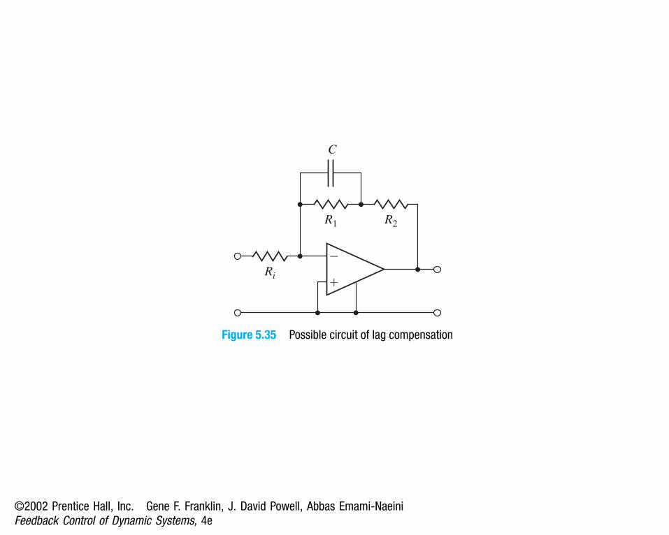
Figure 5.35 Possible circuit of lag compensation
©2002 Prentice Hall, Inc. Gene F. Franklin, J. David Powell, Abbas Emami-NaeiniFeedback Control of Dynamic Systems, 4e

Trim tab dt
Elevator de
(a)
(b)
Figure 5.36 Auto-pilot design in the Piper Dakota, showing elevator and trim tab(Photo courtesy of Denise Freeman)
©2002 Prentice Hall, Inc. Gene F. Franklin, J. David Powell, Abbas Emami-NaeiniFeedback Control of Dynamic Systems, 4e

d t(s) KD (s)1 ��
� e(s)�
Md(s)
��
��
�
de(s) G (s) u (s)
ur(s)de(s)
G (s) u (s)
(a) (b)
Figure 5.37 Block diagrams for auto-pilot design: (a) open loop;(b) feedback scheme excluding trim control
©2002 Prentice Hall, Inc. Gene F. Franklin, J. David Powell, Abbas Emami-NaeiniFeedback Control of Dynamic Systems, 4e
Re(s)
Im(s)
Re(s)
Im(s)
�2�3�4
1.0
0.5
�0.5
�1.0
Im(s)
5
10
�5�10�15�20
Im(s)
�5
�10
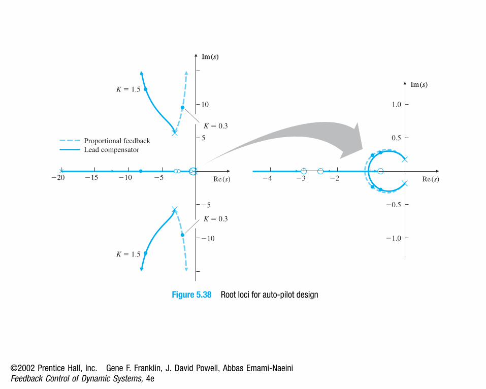
K � 1.5
K � 1.5
K � 0.3
K � 0.3
Proportional feedbackLead compensator
Figure 5.38 Root loci for auto-pilot design
©2002 Prentice Hall, Inc. Gene F. Franklin, J. David Powell, Abbas Emami-NaeiniFeedback Control of Dynamic Systems, 4e

1.5�
1.0�
0.5�
0�0 1 2 3 4 5 6
Lead compensator
Proportional feedbacku
Time (sec)
Figure 5.39 Time-response plots for auto-pilot design
©2002 Prentice Hall, Inc. Gene F. Franklin, J. David Powell, Abbas Emami-NaeiniFeedback Control of Dynamic Systems, 4e

��
�
�
Md
��
��
�
G (s) u ur G (s) u
(a) (b)
DI (s)
Md
d t1
sKI
��
�ur KD (s)
de�
��
Figure 5.40 Block diagram showing the trim-command loop
©2002 Prentice Hall, Inc. Gene F. Franklin, J. David Powell, Abbas Emami-NaeiniFeedback Control of Dynamic Systems, 4e

Re(s)
Im(s)
Re(s)
Im(s)
�1�2�3�4
1.5
1.0
0.5
�0.5
�1.5
�1.0
Im(s)
5
10
15
�5�10�15�20
Im(s)
�5
�10
�15
Figure 5.41 Root locus versus KI : assumes an added integral term and lead compensationwith a gain K = 1.5; roots for KI = 0.15 marked with •
©2002 Prentice Hall, Inc. Gene F. Franklin, J. David Powell, Abbas Emami-NaeiniFeedback Control of Dynamic Systems, 4e

0.2�
0.1�
0�
�0.1�
�0.2�
de
0 1 2 3 4 5 6 7 8 9 10
Time (sec)
(a)
0 5 10 15 20 25 30 35 40 45 50
Time (sec)
(b)
6�
4�
2�
0�
u
Figure 5.42 Step response for the case with an integral term and 5◦ command
©2002 Prentice Hall, Inc. Gene F. Franklin, J. David Powell, Abbas Emami-NaeiniFeedback Control of Dynamic Systems, 4e

��
�
R Ys � 1
1s1KA �
�
�
1
KT
Figure 5.43 Block diagram of a servomechanism structure including tachometer feedback
©2002 Prentice Hall, Inc. Gene F. Franklin, J. David Powell, Abbas Emami-NaeiniFeedback Control of Dynamic Systems, 4e

Re(s)
Im(s)Im(s)
Figure 5.44 Root locus of closed-loop poles of the system in Fig. 5.42 vs. KT
©2002 Prentice Hall, Inc. Gene F. Franklin, J. David Powell, Abbas Emami-NaeiniFeedback Control of Dynamic Systems, 4e

Re(s)
Im(s)Im(s)
Figure 5.45 Root locus vs. K1 = KA + 4 after choosing KT = 1
©2002 Prentice Hall, Inc. Gene F. Franklin, J. David Powell, Abbas Emami-NaeiniFeedback Control of Dynamic Systems, 4e
Re(s)
Im(s)
2
1 1
Im(s)
2 2
2
1�1�2�3 2 3
2
1
�1
�2
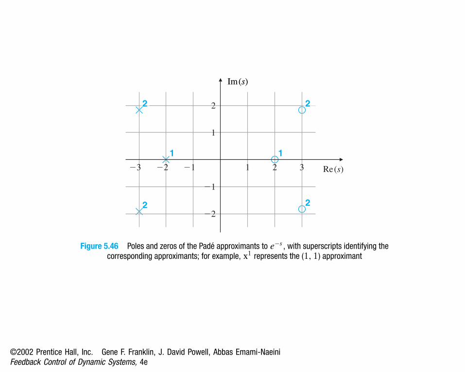
Figure 5.46 Poles and zeros of the Padé approximants to e−s , with superscripts identifying thecorresponding approximants; for example, x1 represents the (1, 1) approximant
©2002 Prentice Hall, Inc. Gene F. Franklin, J. David Powell, Abbas Emami-NaeiniFeedback Control of Dynamic Systems, 4e

Im(s)
Re(s)
No delay
Delay approximated by
first-order lag, Eq. (5.54)
Delay approximated by
Padé (2, 2) approximant, Eq. (5.53)
Delay � e�5s (exact)
0.6
0.4
0.2
�0.2
�0.4
�0.6
�0.5 0.50
Figure 5.47 Root loci for the heat exchanger with and without time delay
©2002 Prentice Hall, Inc. Gene F. Franklin, J. David Powell, Abbas Emami-NaeiniFeedback Control of Dynamic Systems, 4e

u
y
�N
N
a
�a
u
y
u
y
a
�a
u
y
�N
N
�N
N
a
�a
u
y
�N
N
�q
�2q
2q
q
u
y
(a) (b) (c)
(d) (e) (f)
Slope K0
Slope K0
Figure 5.48 Nonlinear elements with no dynamics: (a) saturation, (b) relay, (c) relay with deadzone, (d) gain with dead zone, (e) preloaded spring, or coulomb plus viscous friction,
and (f) quantization
©2002 Prentice Hall, Inc. Gene F. Franklin, J. David Powell, Abbas Emami-NaeiniFeedback Control of Dynamic Systems, 4e

�u�
K
N/a
a Input magnitude
Gai
n
Figure 5.49 General shape of the effective gain of saturation
©2002 Prentice Hall, Inc. Gene F. Franklin, J. David Powell, Abbas Emami-NaeiniFeedback Control of Dynamic Systems, 4e

��
�
r yK0.4�0.4
�0.4
0.4
Saturation
s2s � 1
Figure 5.50 Dynamic system with saturation
©2002 Prentice Hall, Inc. Gene F. Franklin, J. David Powell, Abbas Emami-NaeiniFeedback Control of Dynamic Systems, 4e

Re(s)
Im(s)Im(s)
�1
K � 1
Figure 5.51 Root locus of (s + 1)/s2 , the system in Fig. 5.50 with the saturation removed
©2002 Prentice Hall, Inc. Gene F. Franklin, J. David Powell, Abbas Emami-NaeiniFeedback Control of Dynamic Systems, 4e

20
18
16
14
12
10
8
6
4
2
00 5 10 15 20 25 30
Time (sec)
12
8y
10
6
4
r � 2
Figure 5.52 Step responses of system in Fig. 5.50 for various input step sizes
©2002 Prentice Hall, Inc. Gene F. Franklin, J. David Powell, Abbas Emami-NaeiniFeedback Control of Dynamic Systems, 4e

��
�
R YK
1
s3
(s � 1)2
1
u
Figure 5.53 Block diagram of a conditionally stable system
©2002 Prentice Hall, Inc. Gene F. Franklin, J. David Powell, Abbas Emami-NaeiniFeedback Control of Dynamic Systems, 4e

Imag
e ax
is
�6 �1�2�3�4�5 20 1
Real axis
�3
�2
�1
0
1
2
3
Figure 5.54 Root locus for G(s) = (s + 1)2/s3 from system in Fig. 5.53
©2002 Prentice Hall, Inc. Gene F. Franklin, J. David Powell, Abbas Emami-NaeiniFeedback Control of Dynamic Systems, 4e

Am
plitu
de
0 2018161412108642
Time (sec)
r � 3.475
32
1
�10123456789
Figure 5.55 Step responses of system in Fig. 5.52
©2002 Prentice Hall, Inc. Gene F. Franklin, J. David Powell, Abbas Emami-NaeiniFeedback Control of Dynamic Systems, 4e

��
�
R YK 0.10.1
0.1
s2 � 0.2s � 11
s1U
Figure 5.56 Block diagram of a system with an oscillatory mode
©2002 Prentice Hall, Inc. Gene F. Franklin, J. David Powell, Abbas Emami-NaeiniFeedback Control of Dynamic Systems, 4e

Imag
e ax
is
�2 �1.5 �1�2.5 �0.5�3 0.5 10
Real axis
�1.5
�1
�0.5
0
0.5
1
1.5
K � 0.5
Figure 5.57 Root locus for the system in Fig. 5.56
©2002 Prentice Hall, Inc. Gene F. Franklin, J. David Powell, Abbas Emami-NaeiniFeedback Control of Dynamic Systems, 4e

0 50 100 150
Time (sec)
0
1
2
3
4
5
6
7
8
9
Am
plitu
de
r � 8
r � 4
r � 1
Figure 5.58 Step responses of system in Fig. 5.56
©2002 Prentice Hall, Inc. Gene F. Franklin, J. David Powell, Abbas Emami-NaeiniFeedback Control of Dynamic Systems, 4e

Re(s)
Im(s)Im(s)Im(s)
�0.5�1.0
0.5
�0.5
�10.0
Figure 5.59 Root locus including compensation
©2002 Prentice Hall, Inc. Gene F. Franklin, J. David Powell, Abbas Emami-NaeiniFeedback Control of Dynamic Systems, 4e

��
�
R Y0.1
0.1
s2 � 0.2s � 11
s1u
21
(s � 10)2s2 � 0.18s � 0.81
0.81100
Figure 5.60 Block diagram of the system with a notch filter
©2002 Prentice Hall, Inc. Gene F. Franklin, J. David Powell, Abbas Emami-NaeiniFeedback Control of Dynamic Systems, 4e

255 10 15 200 35 40 45 5030
Time (sec)
0
0.5
1
1.5
2
2.5
3
3.5
4
40.5
Am
plitu
de
r � 4
r � 2
Figure 5.61 Step responses of the system in Fig. 5.60
©2002 Prentice Hall, Inc. Gene F. Franklin, J. David Powell, Abbas Emami-NaeiniFeedback Control of Dynamic Systems, 4e

(a) (b) (c)
(d) (e) (f)
Figure 5.62 Pole-zero maps
©2002 Prentice Hall, Inc. Gene F. Franklin, J. David Powell, Abbas Emami-NaeiniFeedback Control of Dynamic Systems, 4e

��
YR 5s � 10
2s1
s � lK1
0.1 0.2
��
�
��
�
�
Figure 5.63 Control system for Problem 11
©2002 Prentice Hall, Inc. Gene F. Franklin, J. David Powell, Abbas Emami-NaeiniFeedback Control of Dynamic Systems, 4e

��
Rc � s
c � 16ss29
Y�
Figure 5.64 Control system for Problem 12
©2002 Prentice Hall, Inc. Gene F. Franklin, J. David Powell, Abbas Emami-NaeiniFeedback Control of Dynamic Systems, 4e

Y��
�R G (s)
H (s)
Figure 5.65 Feedback system for Problem 5.15
©2002 Prentice Hall, Inc. Gene F. Franklin, J. David Powell, Abbas Emami-NaeiniFeedback Control of Dynamic Systems, 4e

��
�R YK
s(s2 � 4s � 5)s � 3
s � 11
Figure 5.66 Feedback system for Problem 5.16
©2002 Prentice Hall, Inc. Gene F. Franklin, J. David Powell, Abbas Emami-NaeiniFeedback Control of Dynamic Systems, 4e

Y��
�R
s(s � 2)5
1 � as
Figure 5.67 Control system for Problem 5.17
©2002 Prentice Hall, Inc. Gene F. Franklin, J. David Powell, Abbas Emami-NaeiniFeedback Control of Dynamic Systems, 4e

��
�R YK
(a)
��
�R YK
(b)
s (s � 2)(s2 � 2s � 10)s � 2
s(s � 5)(s � 6)(s2 � 2s � 1)s2 � s � 2
Figure 5.68 Feedback systems for Problem 5.20
©2002 Prentice Hall, Inc. Gene F. Franklin, J. David Powell, Abbas Emami-NaeiniFeedback Control of Dynamic Systems, 4e

��
�R Y
s � 13s � 1( )K
s2(s2 � 100)s2 � 81
Figure 5.69 Feedback system for Problem 5.22
©2002 Prentice Hall, Inc. Gene F. Franklin, J. David Powell, Abbas Emami-NaeiniFeedback Control of Dynamic Systems, 4e

��
Y(s)R (s) 10 ��
��s1
Ks
s1
��
�
Figure 5.70 Feedback system for Problem 5.23
©2002 Prentice Hall, Inc. Gene F. Franklin, J. David Powell, Abbas Emami-NaeiniFeedback Control of Dynamic Systems, 4e

Y��
�R D(s) G(s)
Figure 5.71 Unity feedback system for Problems 5.24 to 5.30 and 5.35
©2002 Prentice Hall, Inc. Gene F. Franklin, J. David Powell, Abbas Emami-NaeiniFeedback Control of Dynamic Systems, 4e

u
iv0
Photodetector
e
Light
Solenoid
Ball
x
Figure 5.72 Elementary magnetic suspension
©2002 Prentice Hall, Inc. Gene F. Franklin, J. David Powell, Abbas Emami-NaeiniFeedback Control of Dynamic Systems, 4e

x��
�
H(s)
s21
Sensor
Fc F
Figure 5.73 Block diagram for rocket-positioning control system
©2002 Prentice Hall, Inc. Gene F. Franklin, J. David Powell, Abbas Emami-NaeiniFeedback Control of Dynamic Systems, 4e

Y��
�
1
s21
R K �
�
W2
��
�
W1
�
(s � 6 � 2j)(s � 6 � 2j)100
s�
�
�
Figure 5.74 Control system for Problem 5.34
©2002 Prentice Hall, Inc. Gene F. Franklin, J. David Powell, Abbas Emami-NaeiniFeedback Control of Dynamic Systems, 4e

Y��
�D (s) �
��
W
s(s � 1)1
R
Figure 5.75 Control system for Problem 5.36
©2002 Prentice Hall, Inc. Gene F. Franklin, J. David Powell, Abbas Emami-NaeiniFeedback Control of Dynamic Systems, 4e
Gears�
��
KA
va
1000 �
1000 �C
ef
Amplifier Motor
Outputpotentiometer
Inputpotentiometer
u i uo
km
Jm
JL
Feedback filter
Kpot Kpot
eo
ei
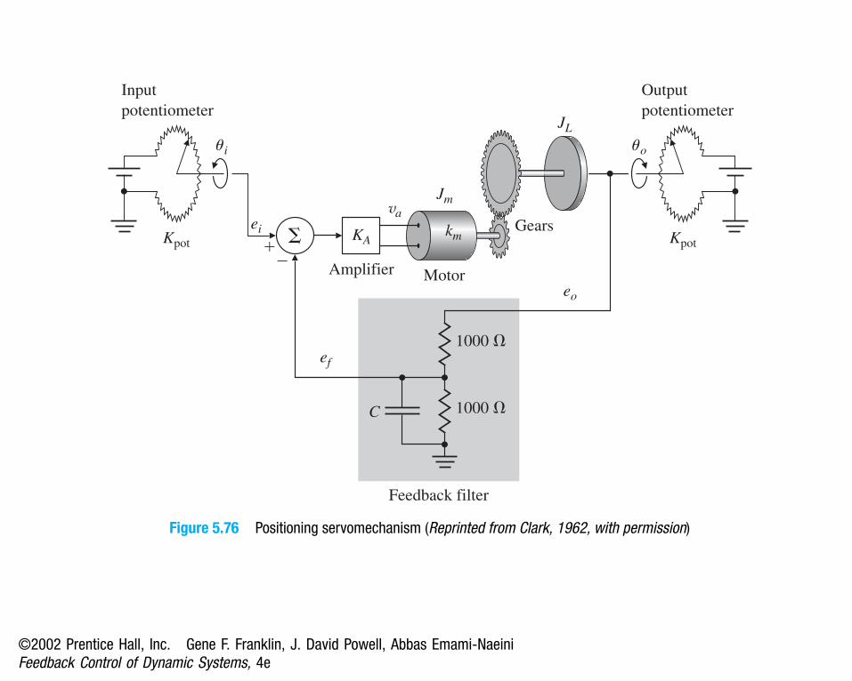
Figure 5.76 Positioning servomechanism (Reprinted from Clark, 1962, with permission)
©2002 Prentice Hall, Inc. Gene F. Franklin, J. David Powell, Abbas Emami-NaeiniFeedback Control of Dynamic Systems, 4e

Trolley or cart
y
u
Figure 5.77 Figure of cart-pendulum for problem 5.39
©2002 Prentice Hall, Inc. Gene F. Franklin, J. David Powell, Abbas Emami-NaeiniFeedback Control of Dynamic Systems, 4e

0� 10� 20� 30� 40� 50�
Figure 5.78 USCG cutter Tampa (902)
©2002 Prentice Hall, Inc. Gene F. Franklin, J. David Powell, Abbas Emami-NaeiniFeedback Control of Dynamic Systems, 4e

uu
��
��
��
Elevatorservo
s � 10Ku r
Me
Mp Aircraftdynamics
s2 � 4s � 5s � 3
s1
KTu
Rate gyro
KTAttitudesensor
1
Figure 5.79 Golden Nugget Airlines autopilot
©2002 Prentice Hall, Inc. Gene F. Franklin, J. David Powell, Abbas Emami-NaeiniFeedback Control of Dynamic Systems, 4e

��
�R Y
s2 � 51s � 5501
D(s)u
H(s)
s1
Sensor
Compensator
Figure 5.80 Control system for Problem 5.42
©2002 Prentice Hall, Inc. Gene F. Franklin, J. David Powell, Abbas Emami-NaeiniFeedback Control of Dynamic Systems, 4e

��
�R Y
sK2K1(1 � ) s (s � 1)(s � 0.5)
1E U
Figure 5.81 Feedback system for Problem 5.43
©2002 Prentice Hall, Inc. Gene F. Franklin, J. David Powell, Abbas Emami-NaeiniFeedback Control of Dynamic Systems, 4e

Y��
�KR
s3(s � 1)2e u
Figure 5.82 Control system for Problem 5.44
©2002 Prentice Hall, Inc. Gene F. Franklin, J. David Powell, Abbas Emami-NaeiniFeedback Control of Dynamic Systems, 4e

Y��
�KR �
�
�
s � 11
s1
KT
Figure 5.83 Control system for Problem 5.45
©2002 Prentice Hall, Inc. Gene F. Franklin, J. David Powell, Abbas Emami-NaeiniFeedback Control of Dynamic Systems, 4e
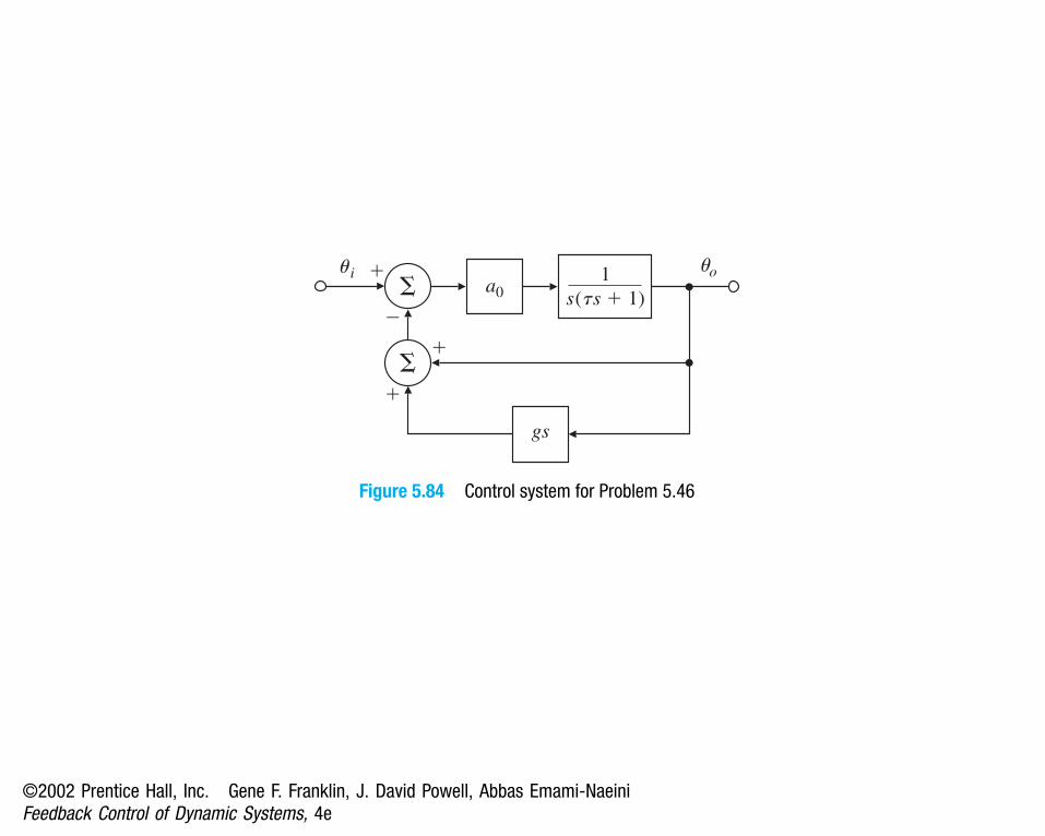
��
�a0
u i
��
�
gs
s(ts � 1)1 uo
Figure 5.84 Control system for Problem 5.46
©2002 Prentice Hall, Inc. Gene F. Franklin, J. David Powell, Abbas Emami-NaeiniFeedback Control of Dynamic Systems, 4e

��
�KR Y
s � 0.011
e�s
Figure 5.85 Control system for Problem 5.47
©2002 Prentice Hall, Inc. Gene F. Franklin, J. David Powell, Abbas Emami-NaeiniFeedback Control of Dynamic Systems, 4e