vw2009 architect tutorial sample
TRANSCRIPT

8/8/2019 VW2009 Architect Tutorial Sample
http://slidepdf.com/reader/full/vw2009-architect-tutorial-sample 1/18
Vectorworks Architect
Tutorial Manual by Jonathan Pickup

8/8/2019 VW2009 Architect Tutorial Sample
http://slidepdf.com/reader/full/vw2009-architect-tutorial-sample 2/18
©2008 Jonathan Pickup | Vectorworks Architect Tutorial Manual i
Table of Contents
Introduction .....................................................................................iii
Step 1 Layer and Model Setup ...................................................1Document Setup ..................................................................................................1Layer Setup (Model Setup) .................................................................................7
Step 2 Property Line ................................................................ 13
Step 3 Creating the Site Model ................................................17Creating the Site Model .....................................................................................19Height in Relation to Boundary ..........................................................................32
Step 4 Quick Bulk and Location ............................................... 43Creating the Lower Floor ...................................................................................43Creating the Upper Floor ...................................................................................46Linking Spaces to Site Plan ...............................................................................52
Step 5 Creating The Walls ....................................................... 63Creating Basement Walls ..................................................................................63Creating Upper Floor Walls ...............................................................................68
Step 6 Creating The Roof ....................................................... 83Existing Roof ....................................................................................................83
Step 7 Concept Drawings ...................................................... 103Plan Viewports.................................................................................................103
Step 8 Doors and Windows .....................................................111Standard Vectorworks Doors and Windows. ...................................................113WinDoor Manager ...........................................................................................118Updating the Concept Plan .............................................................................125
Step 9 Site Modifiers ..............................................................129Roads ..............................................................................................................130Pads and Fences ............................................................................................135
Step 10 Stairs........................................................................... 141
Step 11 Annotation ................................................................... 147Standard Title Blocks (Drawing Border) ..........................................................147Drawing Labels ................................................................................................150
Notes, Keynotes and Callouts .........................................................................153Step 12 Working Drawings ....................................................... 161
Drawing 01 - Site Plan .....................................................................................161Drawing 02 - Foundation Plan .........................................................................163Drawing 03 - Framing Plan ..............................................................................167
Other Drawings .....................................................................................................................176Thank You ........................................................................................................................176

8/8/2019 VW2009 Architect Tutorial Sample
http://slidepdf.com/reader/full/vw2009-architect-tutorial-sample 3/18
©2008 Jonathan Pickup | Vectorworks Architect Tutorial Manual 1
Step 1 Layer and Model Setup
Document Setup
We will set up the file from the beginning, from a blank document. Vectorworks has set up
commands to make it easier to set up the file. When you have set up the file, it can become a
template file that you can use to start every new job, saving you a lot of setup time.
Go to the Menu Bar.•
Choose• File > New...
This opens a dialog box for you•
to choose Blank Document.
A blank file opens with a layer •scale of 1:1 and a letter-size page.
We should set up our page first.•

8/8/2019 VW2009 Architect Tutorial Sample
http://slidepdf.com/reader/full/vw2009-architect-tutorial-sample 4/18
2 Vectorworks Architect Tutorial Manual | © 2008 Jonathan Pickup
Go to the• Menu Bar .
Choose• File > Page Setup...
This opens a dialog box for you to set up the page size.•
This dialog box allows you to set•
up the printer that you are using.
Click on the• Printer Setup... button.
This dialog box will vary depending on your printer.•
On a Macintosh the dialog box will look similar to this•
picture. Set the printer, page size and page orientation.
Click on the• OK button.
On a Windows machine the dialog box will look•
similar to this picture. Set the printer, page size
and page orientation.
Click on the• OK button.

8/8/2019 VW2009 Architect Tutorial Sample
http://slidepdf.com/reader/full/vw2009-architect-tutorial-sample 5/18
©2008 Jonathan Pickup | Vectorworks Architect Tutorial Manual 3
This takes you back to the Page Setup•
dialog box.Our drawings are going to be set up•
using Viewports, so the page boundary
won’t be meaningful on our design layers.
Turn off • Show Page Boundary.
Turn off • Show Page Breaks.
Click on the• OK button.
Vectorworks shows the•
new drawing area.
The reference grid may not appear on
the screen due to the density of the grid
at a particular scale and page size.
Go to the• Menu Bar .
Choose• File > Document Settings > Document
Setup...
Document Setup is a quick way to set up the drawing
when you are starting a new project.

8/8/2019 VW2009 Architect Tutorial Sample
http://slidepdf.com/reader/full/vw2009-architect-tutorial-sample 6/18
4 Vectorworks Architect Tutorial Manual | © 2008 Jonathan Pickup
On this dialog box we get the opportunity to check the•
setup of the project as a whole: the units, layer scale,drawing area, grid setting and the title block size.
Click on the• Drawing Units: Change... button. This
will open the Units dialog box for us to set up the
drawing units, primary dimensioning, secondary
dimensioning and area and volume units.
Set your • General Display units to
the settings that you want.
Set the• Dimension Objects
(Primary) to the settings that youwant.

8/8/2019 VW2009 Architect Tutorial Sample
http://slidepdf.com/reader/full/vw2009-architect-tutorial-sample 7/18

8/8/2019 VW2009 Architect Tutorial Sample
http://slidepdf.com/reader/full/vw2009-architect-tutorial-sample 8/18
6 Vectorworks Architect Tutorial Manual | © 2008 Jonathan Pickup
Click on the• Drawing Grids: Change... button. This
will open the Set Grid dialog box for us to set the snapand reference grids for our file.
Choose• Grid on the left hand side.
For metric drawings set the snap grid•
to 100mm and the reference grid to
1000mm .
For for imperial drawings set the•
snap grid to 4” and the reference
grid to 3’.
Click on the• OK button.
The reference grid may not appear on the screen due to the density of the grid at a particular
scale and page size.
The Document Setup dialog box now
shows you your setup...
Click on the• OK button.

8/8/2019 VW2009 Architect Tutorial Sample
http://slidepdf.com/reader/full/vw2009-architect-tutorial-sample 9/18
©2008 Jonathan Pickup | Vectorworks Architect Tutorial Manual 7
Layer Setup (Model Setup)
We need to break up the project into a series of manageable chunks to make it easier to draw
the building. These chunks are called layers, and at the beginning we will have a layer for
each storey of the building, a layer for the site plan, a layer for the site survey data and a layer
for the contour plan.
If you are not familiar with layers please refer to the Vectorworks Essential Manual, which has
a series of exercises to explain layers.
We can create a few layers now to draw the existing building, then add more layers later as
we need them. There is a way to have a file set up with most of the design layers and sheetlayers, called Layer and Class standards. This allows you to grab a few layers when you want
them. For more information on creating a Layer and Class Standard, refer to the Vectorworks
Productivity Manual available from www.archoncad.com or www.Vectorworks.net.
One way of creating the layers is to use the Model Setup Command. This will create some of
our layers for us and input the correct heights. It’s also a graphical way of creating the layers
at the right height, so it will make it easier to understand layers and their heights. Our building
is similar to this sketch, and we will use these dimensions for our model setup.

8/8/2019 VW2009 Architect Tutorial Sample
http://slidepdf.com/reader/full/vw2009-architect-tutorial-sample 10/18
8 Vectorworks Architect Tutorial Manual | © 2008 Jonathan Pickup
Go to the Menu Bar.•
Choose• File > Document Settings > Model Setup...
This command is for setting up the project as a model,
setting the number of floors, the heights of the floors, etc.
We had a house with foundations (400mm high), ground
floor slab (100mm thick), a lower floor with a stud height
of 2464mm, an upper floor with a stud height of 2490mm
and a roof.
The Model Setup dialog box can be used to set up all the model layers for this project, but we
will still need to add other layers to help us make this project. When you use this command on
a new file, you get the first dialog box to set up the number of floors.
2 floors (the basement will be the lower floor).•
No basements.•
Click on the• OK button.
On the next dialog box, set the layer
heights for each layer of the project.
For this project we will not be using the•
correct project levels for the layer heights.
We will use the upper floor as the main floor.
This will be set at Z=0, and all the other floors will be related to this.
The foundation should be below the ground•
floor slab. The foundations will vary due to
the site conditions, but enter an elevation
value of -2864mm (-9’5”) (so that the
foundations are 400mm (1’4”) below the
lower floor).

8/8/2019 VW2009 Architect Tutorial Sample
http://slidepdf.com/reader/full/vw2009-architect-tutorial-sample 11/18
©2008 Jonathan Pickup | Vectorworks Architect Tutorial Manual 9
The lower floor, Mod-Floor-1, has its•
Elevation set to -2464mm (-8’1”) (so that itis below the main floor).
The walls will go from the top of the slab to•
the top of the floor above, so the Ceiling
Height need to be 2464mm (8’1”).
The slab thickness for this project is 100mm•
(the floor is a concrete slab).
Turn off the option to create Slab Layers,•
which would give us extra layers that wedon’t need.
The upper floor, Mod-Floor-2, is the main•
floor, and we want to set its Elevation to 0.
The walls will go from the top of the floor to•
the underside of the roof above, so the walls
need to be 2490mm (8’2”).

8/8/2019 VW2009 Architect Tutorial Sample
http://slidepdf.com/reader/full/vw2009-architect-tutorial-sample 12/18
10 Vectorworks Architect Tutorial Manual | © 2008 Jonathan Pickup
Finally the roof has its elevation set at• Z=0.
This allows us to use the bearing height of the roof to control the 3D height of the roof.
This is the easiest way to control the roof. You
can use the bearing height of the individual roof
planes to control the height rather than the
layer height.
Click on the• OK Button.
You can see all the new layers in the• Navigation palette.
We can edit the layers in the Navigation palette, but the•
Organization dialog box gives us additional information.
Before you do anything else, make sure that you save your file.•
Get into the habit of saving your file on a regular basis.
From the Menu Bar choose• File > Save...

8/8/2019 VW2009 Architect Tutorial Sample
http://slidepdf.com/reader/full/vw2009-architect-tutorial-sample 13/18

8/8/2019 VW2009 Architect Tutorial Sample
http://slidepdf.com/reader/full/vw2009-architect-tutorial-sample 14/18
12 Vectorworks Architect Tutorial Manual | © 2008 Jonathan Pickup
Click on the• Scale button.
Change the scale to• 1:200.
Click on the• OK button.
Now the layers have the•
settings that we want.
Click on the• OK button.
The layer scales can be changed at any time.
Right mouse click on any layer in the Navigation•palette to edit, duplicate or remove layers.

8/8/2019 VW2009 Architect Tutorial Sample
http://slidepdf.com/reader/full/vw2009-architect-tutorial-sample 15/18
©2008 Jonathan Pickup | Vectorworks Architect Tutorial Manual 13
Step 2 Property Line
When you want to draw a property line (site boundary) you will notice that surveyors usually
use 0º for North while Vectorworks uses horizontally across to the right as 0º.
You may think that this causes us a problem. It doesn’t because we have a tool that will
translate the surveyors information into native Vectorworks information. This tool is called the
Property Line Tool.
Make sure that the Active Layer is• Mod-Site Plan.
Select the• Property Line Tool to draw the site.
Go to the• Tool Bar .
Click on the• Preferences button.
Choose the• Simple Dialog option.
Click on the• OK button.
In some countries, surveyors always assume that the
bearings are measured from north through east so that
true north is 0º and true east is 90º. The simple dialog box
works very well for this method. In other countries you will
need to use N_E or N_W depending on the bearings from
the surveyor.

8/8/2019 VW2009 Architect Tutorial Sample
http://slidepdf.com/reader/full/vw2009-architect-tutorial-sample 16/18
14 Vectorworks Architect Tutorial Manual | © 2008 Jonathan Pickup
Click once in the drawing area, near •
the bottom, to start.The Create Property Line dialog box•
will open.
Type in the surveyors bearings from•
the plan. You can use a decimal point
between the degrees, minutes and
seconds, or you can use DMS for the
degrees, minutes and seconds.
Type in the bearing,• 19.01.10 (19d01m10s).
Type in the bearing length• 41.855m (137.32’).
Click on the• Enter button or hit
the Enter key and you should
notice a line on the screen.
Vectorworks draws the first
boundary line.
Type in the second distance and bearing.•
Type in the bearing,• 285.57.50 (285d57m50s).
Type in the bearing length• 16.278m (53.41’).
Click on the• Enter button or hit the Enter key.

8/8/2019 VW2009 Architect Tutorial Sample
http://slidepdf.com/reader/full/vw2009-architect-tutorial-sample 17/18
©2008 Jonathan Pickup | Vectorworks Architect Tutorial Manual 15
Vectorworks draws the next boundary•
line and connects it to the firstboundary.
Sooner or later though, you will find that
the surveyor has measured the boundary
in the opposite direction to the way you
are drawing it. Don’t worry about this.
Type in the bearing normally but type in
the distance as a negative distance. Youwill find that it works out OK.
Type in the bearing,• 24.08.34 (24d08m34s).
Type in the bearing length -• 39.269m (128.84’).
Click on the• Enter button or hit the Enter key.
The site is complete if you click on•
the Close Shape tick box.
Click on the• Done Button.
8/8/2019 VW2009 Architect Tutorial Sample
http://slidepdf.com/reader/full/vw2009-architect-tutorial-sample 18/18
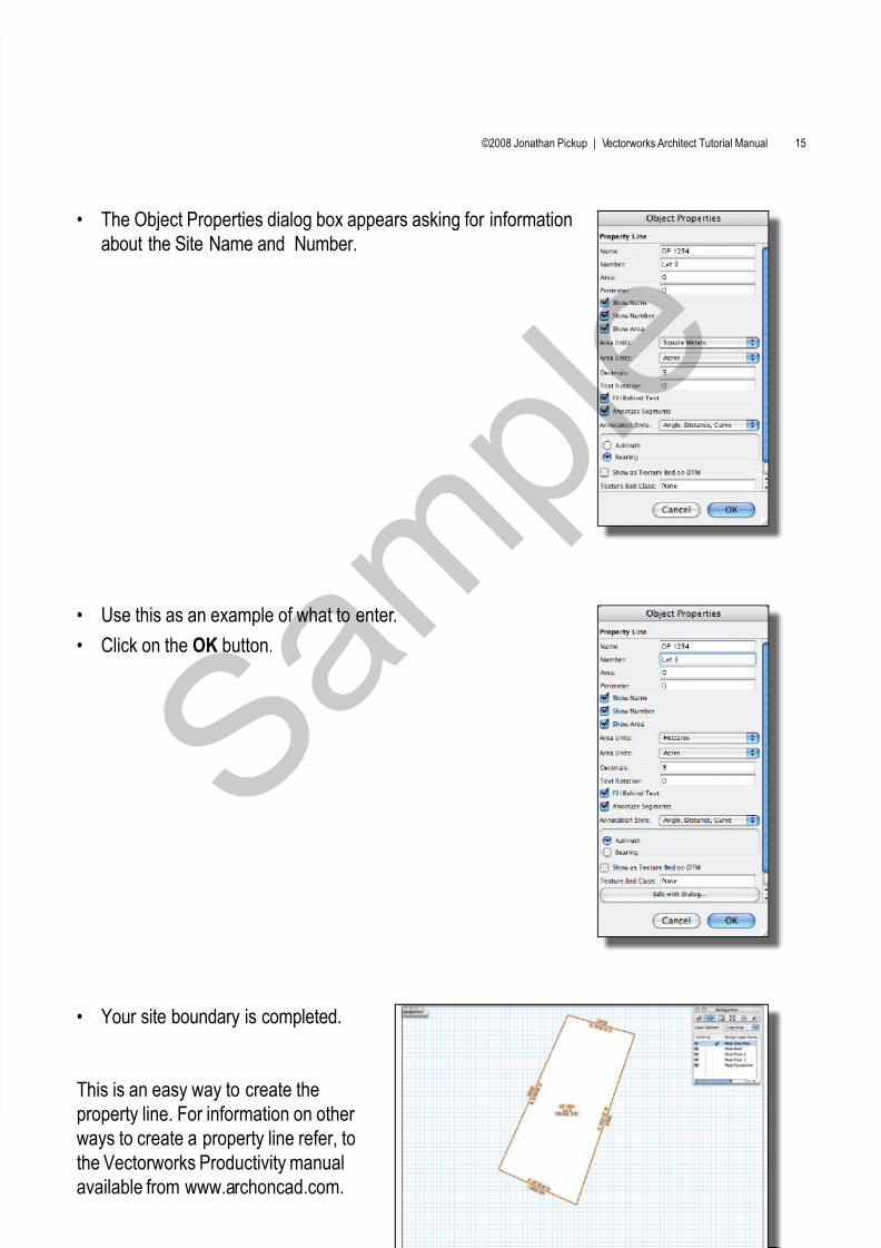
The Object Properties dialog box appears asking for information•
about the Site Name and Number.
Use this as an example of what to enter.•
Click on the• OK button.
Your site boundary is completed.•
This is an easy way to create the
property line. For information on other ways to create a property line refer, to
the Vectorworks Productivity manual
available from www.archoncad.com.