vth15 series user’s manual - msistemi.com · under calling, status, click this button to answer...
TRANSCRIPT

VTH15 Series User’s Manual
V4.0.0

Table of Contents
1. General Introduction ................................................................................................... 5
1.1 Model List ........................................................................................................................... 5
1.2 Front Panel .......................................................................................................................... 6
1.2.1. Button ......................................................................................................................... 8
1.2.2. Indicator ..................................................................................................................... 9
1.3 Rear Panel ......................................................................................................................... 10
1.3.1. VTH15 Series Model CH ............................................................................................ 10
1.3.2. VTH2221A ................................................................................................................. 11
2. Installation and Debugging ....................................................................................... 12
2.1 Install Device ..................................................................................................................... 12
2.1.1. Embedded Box.......................................................................................................... 12
2.1.2. Direct Installation ..................................................................................................... 14
2.2 Cabling .............................................................................................................................. 15
2.3 Debug Device .................................................................................................................... 15
2.3.1. Before Debugging ..................................................................................................... 15
2.3.2. Debugging Step......................................................................................................... 15
2.3.3. Result Verification .................................................................................................... 19
3. Operation .................................................................................................................. 21
3.1 Homepage ......................................................................................................................... 21
3.2 System Settings ................................................................................................................. 22
3.2.2. Project Settings ......................................................................................................... 26
3.2.3. Introduction .............................................................................................................. 27
3.2.4. Version ...................................................................................................................... 27
3.3 Call .................................................................................................................................... 28
3.3.1. Call User .................................................................................................................... 28
3.3.2. Contacts .................................................................................................................... 29
3.3.3. Records ..................................................................................................................... 31
3.4 SOS Call ............................................................................................................................. 32
3.5 Monitor ............................................................................................................................. 33
3.6 Alarm................................................................................................................................. 34

3.6.1. Area Status ............................................................................................................... 34
3.6.2. Mode Settings .......................................................................................................... 37
3.6.3. Arm/Disarm .............................................................................................................. 37
3.6.4. Alarm Record ............................................................................................................ 39
3.7 Smart Home ...................................................................................................................... 40
3.7.1. Home Control ........................................................................................................... 40
3.7.2. Home Config ............................................................................................................. 40
3.8 Message ............................................................................................................................ 40
3.9 Unlock ............................................................................................................................... 41
3.10 Default .............................................................................................................................. 41
4. Appendix 1 Technical Specification ........................................................................... 42

Important Safeguards and Warnings
Please read the following safeguards and warnings carefully before using the product in order
to avoid damages and losses.
Note:
Do not expose the device to lampblack, steam or dust. Otherwise it may cause fire or
electric shock.
Do not install the device at position exposed to sunlight or in high temperature.
Temperature rise in device may cause fire.
Do not expose the device to humid environment. Otherwise it may cause fire.
The device must be installed on solid and flat surface in order to guarantee safety
under load and earthquake. Otherwise, it may cause device to fall off or turnover.
Do not place the device on carpet or quilt.
Do not block air vent of the device or ventilation around the device. Otherwise,
temperature in device will rise and may cause fire.
Do not place any object on the device.
Do not disassemble the device without professional instruction.
Warning:
Please use battery properly to avoid fire, explosion and other dangers.
Please replace used battery with battery of the same type.
Do not use power line other than the one specified. Please use it properly. Otherwise,
it may cause fire or electric shock.
Special Announcement
This manual is for reference only.
All the designs and software here are subject to change without prior written notice.
owners.
If there is any uncertainty or controversy, please refer to the final explanation of us.

1. General Introduction
1.1 Model List
This manual is for the following product models; please carefully check your model and
corresponding functions.
VTH Series Model Front Camera
Screen SD Card
VTH15 series model A
VTH1510A Not support Resistive touch screen
Not support
VTH1520A Not support Resistive touch screen
Support
VTH1520AS-H Not support Resistive touch screen
Support
VTH15 series model B
VTH1550B Not support Capacitive touch screen
Not support
VTH1560B(W) Not support Capacitive touch screen
Support
VTH15 series model CH
VTH1510CH Not support Resistive touch screen
Not support
VTH1520CH Support Resistive touch screen
Support
VTH1580CS Not support Capacitive touch screen
Support
VTH2X series model A
VTH2221A Not support Resistive touch screen
Not support
Chart 1-1

1.2 Front Panel
Figure 1-1 VTH15 Series Model A

Figure 1-2 VTH15 Series Model B
Figure 1-3 VTH15 Series Model CH
Note:
Only VTH1520CH-C model has front camera and other models do not have front camera.

Figure 1-4 VTH2X Series Model A
1.2.1. Button
Different models of VTH may have slightly different button locations, but same silk-screens still
correspond to the same function. See Figure 1-5 and Figure 1-6.
Figure 1-5
Figure 1-6

No. Icon Name Note
1 SOS Emergent call to center.
2
Arm/Menu Click this button to return to main menu or arm.
3
Call
Under calling, status, click this button to answer
call. During a call, click this button to hang up.
4
Monitor Monitor VTO video.
5
Unlock
During incoming call, calling, monitoring status,
click this button to unlock.
Chart 1-2
1.2.2. Indicator
Some 7 inch VTHs only have power and info indicator. Indicator of different models of VTH
may vary.
Indicator of VTH 15 series model A and VTH2X model A are in Figure 1-7.
Figure 1-7
Indicator
Name
Description
Power Power cable is correctly connected, after device boot up, power
indicator is green NO.
Info When there is unread info, light is NO, after info is read, light is
off.
Network
Communication with VTO is normal, light on; communication
with VTH is abnormal, light off. Only VTH15 series model A has
network indicator.
DND
When you enable DND function, DND indicator is green NO.
Note
Only VTH15 series model A has DND indicator.
See Ch 3.2.1.5.
Chart 1-3

1.3 Rear Panel
Ports of VTH of different models may have different locations, but corresponding ports’
functions stay the same.
The following are two examples.
1.3.1. VTH15 Series Model CH
Figure 1-8
No. Name Description
1 Alarm Port 8-ch alarm, please refer to tag.
2 Debug Port Extension port, for RS485 communication port.
3 Network Port Plug in network cable.
4 Alarm Output
Note:
Reserved port.
5 Power Port Connect to 2-pin green 12V power supply.
Chart 1-4

1.3.2. VTH2221A
Figure 1-9
No Name Description
1 Power Port Connect to 2-pin green 12V power supply.
2 Network Port Plug in network cable.
3
12-pin Port
Alarm input 1 Alarm input 2 Alarm input 3 Alarm input 4 GND Alarm input 5 Alarm input 6 Alarm input 7 Alarm input 8 GND
Alarm output NO(not included)
Alarm output COM(not included)
Chart 1-5

2. Installation and Debugging
2.1 Install Device
The device has two installation methods: embedded box and direction installation.
Warning:
Avoid installation in poor environment, such as condensation, high temperature, oil
stain, dust, corrosion or direct sunlight.
After device is plugged to power, if you find any abnormal phenomenon, you shall
immediately unplug network cable and cut power supply. You may re-plug in power
after troubleshooting.
Project installation and debugging must be done by professionals. Please do not
open the device in case of failure, and please contact after sales service.
2.1.1. Embedded Box
Embedded box has 86 box and metal case.
2.1.1.1. 86 Box
Applicable to all devices.
Screw
Component Name Figure Quantity
M4×30 cross slot pan
head screw 2
Chart 2-1
Steps
Note:
During installation, distance from the device center to the ground shall be 1400mm~16mm.
Step 1. Embed the 86 box into a wall at appropriate height (if there is embedded 86 box
already, please skip this step).
Step 2. Fix installation bracket on 86 box with 2 screws (M4×30).

Step 3. Face VTH back toward installation bracket. Hang VTH back on the bracket from up to
down.
Step 4. Check whether VTH is installed in place.
Figure 2-1
2.1.1.2. Metal Case
Applicable for model CH device only, including VTH1510CH and VTH1520CH.
Screw
Component Name Figure Quantity
M4×30 cross slot pan
head screw 3
Chart 2-2
Steps
Note:
During installation, distance from the device center to the ground shall be 1400mm~16mm.
Step 1. Embed the metal case into a wall at appropriate height.
Step 2. Fix installation bracket on metal case with screws.
Step 3. Fix the device unit on installation bracket with buckle.

Figure 2-2
2.1.2. Direct Installation
Direct installation is to pull all device cables from side without digging holes on wall as exit
hole.
Step 1. Install bracket on tall, fix it with screw (M4*30).
Step 2. Fix the device unit on installation bracket, fix with buckle.
Figure 2-3

2.2 Cabling
See Ch 1.3 for detailed port.
2.3 Debug Device
After you have successfully set VTH and VTO, you start talk.
2.3.1. Before Debugging
Debugging personnel should be familiar with the relevant information, understand the
device installation, wiring and use.
Debugging personnel to detect whether there is a short circuit or open circuit, confirm line
is normal, plug the device to power.
After debugging complete, clean up the site (including joint processing, device fixing, etc.).
2.3.2. Debugging Step
Note:
Project Settings interface is for engineer only. The entrance password is 888888.
Step 1. Settings>Project Settings.
Step 2. Enter project setting password (888888 by default).
See Figure 2-4.

Figure 2-4
Step 3. Set VTH room no.
Warning:
VTH room no. must match VTH short no. set on VTO WEB page.
If this VTH is set as master VTH, then select “Master”.
1. Fill in room no., local IP, subnet mask, gateway and etc.
2. Click OK to save.
If this VTH is set as extension, click “Master” to select extension.
1. Fill in room no., master IP, subnet mask, gateway and etc.
Note:
Some of extension config will be synced with master VTH automatically, and cannot
be changed. See Figure 2-5.

Figure 2-5
2. Click OK to save.
Note:
You also can enable DHCP, to auto get device IP, subnet mask and gateway.
Step 4. Set SIP server.
Step 1. Click SIP Server. See Figure 2-6.
Figure 2-6
Step 2. See Chart 2-3 to set SIP server.

Parameter Note
IP Address SIP server IP address.
Network Port SIP server port no., default is 5060.
Username Login SIP server username and password, default
username is the room no. of VTH. Password
Realm SIP server domain registered, which can be blank.
Chart 2-3
Step 3. Set enable status to ON.
Step 4. Click OK to save.
Step 5. Add VTO info.
Step 6. Click Network. See Figure 2-7.
Step 7. Fill in VTO name, VTO IP address, set Enable Status to ON.
Figure 2-7
If you want to add sub VTO, you can press to page down. Fill in sub VTO name, sub VTO IP
Address. Set Enable Status to ON. See Figure 2-8.

Figure 2-8
Step 8. Click OK.
Step 5. IPC Info to view IPC.
You can view IPC info gotten by VTH from SIP server, used to monitor IPC specified by
VTH.
2.3.3. Result Verification
Call VTH room no. from VTO. On VTH, a monitoring window pops up, see Figure 2-9.
On VTH, you can accept call, hang up, unlock and etc., see Chart 2-4.
Note:
VTH1520A\VTH1520AS-H\VTH1520CH\VTH1560B(W)models of VTH has built-in SD card
supporting record, snapshot. If no SD card inserted, the button of record and snapshot will be
grey.

Figure 2-9
Icon Name Note
Accept For incoming call, click to answer.
Hang Up For incoming call, click to hang up.
Unlock When VTH is being called, click to
unlock corresponding VTO. 。
Speaker Used to enable or disable VTH audio output.
MIC Used to enable or disable audio input.
Record
Click to start record, click to end record.
Snapshot Click to snapshot 2 pictutres.
Volume Adjust VTH volume.
Chart 2-4
3. Operation
3.1 Homepage
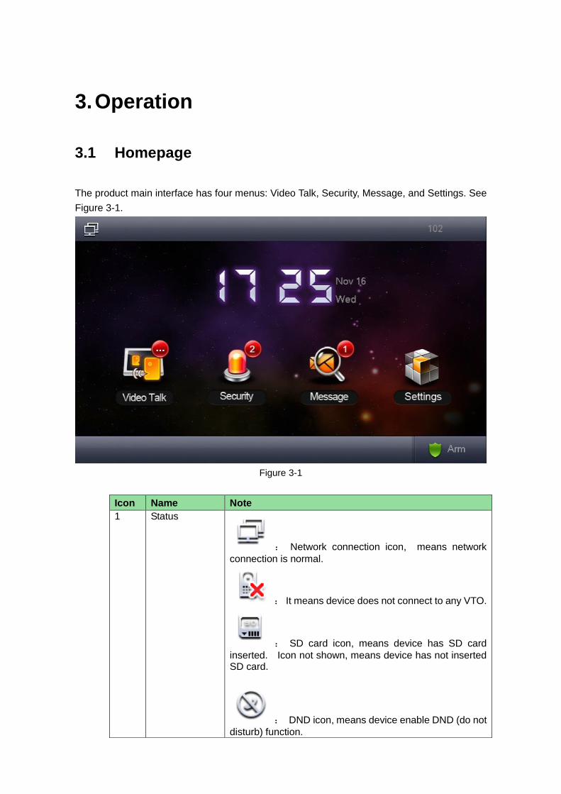
The product main interface has four menus: Video Talk, Security, Message, and Settings. See
Figure 3-1.
Figure 3-1
Icon Name Note
1 Status
: Network connection icon, means network
connection is normal.
: It means device does not connect to any VTO.
: SD card icon, means device has SD card
inserted. Icon not shown, means device has not inserted SD card.
: DND icon, means device enable DND (do not
disturb) function.

Chart 3-1
3.2 System Settings
You can go to System Settings>User Settings, set VTH password, ring, talk, DND, SD card
and etc. You also may restore all user settings to default, see Figure 3-2.
Figure 3-2
3.2.1.1. Password
You can go to System Settings>User Settings>Password, set user password, unlock password,
arm/disarm password, anti-hijack password.
Step 1. System Settings>User Settings>Password. See Figure 3-3.
: Missed icon, means user has missed message.
2 Time Display Show date, week and time.
3 Video Talk View all call records in this face, including missed call and called call, support contact creation.
4 Alarm Set zone type, status, delay time, zone switch and etc. of each zone.
5 Info Search You can view, delete and clear Manager Center released info and alarm info, as well as guest info and record/snapshot.
6 Project Settings
Click this icon, to enter Project Settings.
7 Arm Click this icon, to enter arm mode.

Figure 3-3
Step 2. Select password type, such as user password.
Step 3. Enter old password, new password and confirm password.
Note:
Initial user password is 123456.
Initial unlock password is null.
Initial disarm/arm password is 123456.
Initial anti-hijack password is 654321.
Step 4. Click OK.
3.2.1.2. Display
You can go to System Settings>User Settings>Display, click and to set screen
breightness and screen saver, click OK.
3.2.1.3. Ring
You can go to System Settings>User Settings>Ring, select incoming ring and alarm ring, click
and to set volume, click OK.

3.2.1.4. Talk
You can go to System Settings>User Settings>Talk, click and to set VTO ring time,
VTH ring time, VTO talk time, VTH talk time, monitor time, record time and VTO message time,
see Figure 3-4.
Figure 3-4
Note:
Max time for a VTO to call a VTH is 120 seconds; message time can be 0~90
seconds. When you set message time to 0, then message is not allowed.
VTO calls VTH, when VTH ring time is 15 seconds, if VTO message time is 0
seconds, and VTO call VTH without being accepted in 15 seconds, the VTO auto
hangs up. If VTO message time is not 0, then when VTO call VTH without being
accepted in 15 seconds, it prompts whether you want to leave a message.
3.2.1.5. DND
You can go to System Settings>User Settings>DND, set DND time to eliminate disturbance in
(0~24) hours after setup.
Note:
DND is disabled by default.

3.2.1.6. SD Card
You can go to System Settings>User Settings>SD Card, view SD card free space and format
SD card.
Note:
Please check if you have inserted SD card in the device.
3.2.1.7. Forward
You can go to System Settings>User Settings>Forward, enter number to forward to, see
Figure 3-5.
Figure 3-5
Note:
If you want to forward to room 101, unit 1, building 1, then enter 0101101.
Parameter Note
Always ON means to enable this function, after setup, all incoming calls will be forward to the set number.
Busy ON means to enable this function, after setup, when a user is on a call and there is incoming call from a third party, this incoming call will be forwarded to set number. If not set “no answer”, then if this incoming is hanged up, it stil

Parameter Note
will be forwarded.
No Answer ON means to enable this function, after setup, when an incoming is not accepted, this call will be forwarded. When an incoming call is not accepted exceeding VTH ring time, it will be treated as no answer. Note: You can go to System Settings > User Settings > Talk interface to set VTH ring time.
Chart 3-2
3.2.1.8. Clean
You can go to System Settings>User Settings>Clean, click Clean and wait until screen is
locked, you can clean the screen.
3.2.1.9. Default
Restore all settings in user settings interface to default.
Step 1. Select System Settings>User Settings>Default.
Step 2. In pop-up box enter password, click OK.
Device shows Default interface.
Note:
This verification password is the password of user. You can set in System Settings>
User Settings>Password Settings. Default password is 123456.
Step 3. Click OK.
3.2.1.10. Touch Ring
Slide , ON means touch ring ON. OFF means no touch ring.
3.2.2. Project Settings
Click , and this function is for engineer only. Password to enter Project
Settings is 888888.

3.2.3. Introduction
Go to System Settings>Introduction, view functions and FAQ of this product, see Figure 3-6.
Figure 3-6
3.2.4. Version
Go to System Settings>Version, view or upgrade VTH device software version, see Figure 3-7.

Figure 3-7
3.3 Call
Note:
If both users on a call have camera, then they can have video talk.
3.3.1. Call User
3.3.1.1. Directly Call User
Step 1. Select Video Talk>Call User, see Figure 3-8.

Figure 3-8
Step 2. Enter room no. of party you want to call, click icon to call. When the
party being called accept this call, the bidirectional video talk starts.
Note:
If you want to forward to room 101, unit 1, building 1, then enter 0101101.
3.3.1.2. Call User in Contact
Warning:
Before you call user, please add user in Contacts, see Ch 3.3.2.
Step 1. Select Video Talk> Call User. See Figure 3-8.
Step 2. Click to open Contacts.
Step 3. Select user to call, click Call.
3.3.2. Contacts
You can go to Video Talk>Call User, to add, call, delete, modify, and clear contacts.

To add contact:
Select Video Talk>Call User.
Click . See Figure 3-9.
Figure 3-9
Click Add.
Enter contact first name, last name and room no. See Figure 3-10.
Figure 3-10
Click Save.

Call User
If you call contact, select contact you want to call, and click Call.
Modify Contact Info
If you modify contact info, select contact you want to modify, and click Edit.
Delete Contact
If you delete contact, select contact you want to delete, and click Delete.
Delete All
If you want to clear all contacts, click Delete All. In pop-up box click OK.
3.3.3. Records
You can go to Video Talk>Records to view, store, delete or clear call records of this VTH, and
call back missed call, see Figure 3-11.
Note:
Do not support call back and storage of records on VTO and Manager Center.
Figure 3-11
3.3.3.1. Call Back
If you need to call back (dial back) number, select number you want to dial, click Call.

3.3.3.2. Storage
If you want to save contact, select number you want to save, click Save. Enter first name, last
name, room no. is auto entered, click Save. See Figure 3-12.
Figure 3-12
3.3.3.3. Delete, Delete All
Select call record you want to delete, click Delete to delete the call record.
You also can click Delete All to delete all call records. In pop-up box, click OK.
3.4 SOS Call
Under emergency conditions, click SOS button on device, or in the interface to
call Manager Center. See Figure 3-13.

Figure 3-13
3.5 Monitor
VTH can monitor VTH, fence station or any other specified IPC. Under monitoring, click Call
button on device front panel, to call VTO. When a call starts, VTO automatically accept call.
For example to monitor VTO:
Step 1. Select Video Talk>Monitor>Unit Door Station. See Figure 3-14.
Figure 3-14

Step 2. Select VTO to monitor, see Figure 3-15 and Chart 3-3.
Figure 3-15
Icon Note
Switch to monitor previous channel or next channel of VTO.
Unlock button, may remotely unlock VTO lock.
Record button, click start to record, and click to end record.
Snapshot button, click to snapshot 2 pictures.
Return button, may return to previous menu.
Click to one-click call Manager Center.
Chart 3-3
3.6 Alarm
3.6.1. Area Status
VTH supports 8-ch of area setup.
Note:
In disarm status, you can enter area setup.
You can go to Security>Area Status, set area type, status, delay of each channel.
Step 1. Select Security>Area Status, see Figure 3-16.

Figure 3-16
Parameter Note
Set Set zone, including “Area Type”, “NO/NC”, “Alarm”, “Enter Delay” and “Exit Delay”.
Bypass Area is shielded in this arming. When a device disarms, area when return to status before bypass.
Remove Area is shielded at arming/disarming
Refresh Refresh area.
Chart 3-4
Step 2. Select area to set, click Setup.
Step 3. Enter arm password, which is 123456 by default.
Note:
You can change arm/disarm password in System Settings>User Settings>Password.
Step 4. Click OK. See Figure 3-17.

Figure 3-17
Step 5. According to Chart 3-5. Set “Area Type”, “NO/NC”, “Alarm”, “Enter Delay” and “Exit
Delay”.
Parameter Note
Area No. Set sensor area no., not changed by default.
Area Type According to each zone sensor type, select corresponding zone type, including IR, gas, smoke, SOS, door sensor, theft, perimeter and etc. Note: Area 1~area 3 cannot set area type by default.
NO/NC According to sensor type, select NO/NC type, which shall match type of sensor.
Alarm Alarm status includes instant alarm, delay alarm, bypass and remove.
Instant alarm:this area enters arm status when prompt sound
ends.
Delay alarm:this area enters arm status when delay time ends.
Bypass:this area is shielded in this arming, when device disarms,
area restores to normal working status.
Remove:this area is shielded in arming/disarming.
Enter Delay
When alarm is triggered, if you disarm within delay time, then it will not trigger alarm. If not, after delay time ends, it alarms.
Note: This option is enabled only for delay alarm.
Chart 3-5
Step 6. Click OK.

3.6.2. Mode Settings
Go to Security>Mode Settings, set switch under each area, including Out, In, Sleep and
Custom modes. See Figure 3-18.
Note:
You can set switch under each mode in disarm status only
Figure 3-18
3.6.3. Arm/Disarm
Arm: After being enabled, device enter arm status. When it detects an alarm, device creates
alarm, and upload alarm info.
Disarm: After being enabled, device exit arm status.
3.6.3.1. Arm
Step 1. Click , see Figure 3-19.

Figure 3-19
Step 2. Select one mode.
Step 3. In pop-up box, enter password.
Device beeps, now it has successfully armed.
Note:
Initial arm password is 123456, you can change disarm password in System
Settings>User Settings>Password.
3.6.3.2. Disarm
Step 1. Click Disarm icon at the lower right corner in homepage.
Step 2. In pop-up box, enter password.
If password is correct, then it will prompt that it successfully disarmed. If password is
incorrect, then it will prompt an error, and ask you to retry.
Note:
Initial disarm password is 123456. You can change disarm password in System
Settings>User Settings>Password.
Warning:
In emergency, if you are forces to disarm by someone, you can enter anti-hijack
password. Now alarm system stops working, but device auto upload alarm info
to Manager Center and platform.
Anti-hijack password is 654321. You can change anti-hijack password in
System Settings>User Settings>Password.

3.6.4. Alarm Record
Go to Security>Records, you can view, delete or clear alarm time, area no., event and etc. See
Figure 3-20. Meantime, alarm info will be sent to platform, when each channel has alarm,
device will have a 15s alarm beeps with pop-up alarm interface. See Figure 3-20 and
Figure 3-21.
Figure 3-20
Figure 3-21

3.7 Smart Home
Note:
Functions supported by your project subject to actual product.
3.7.1. Home Control
You can set scene mode of control over light, curtain, air-conditioner.
3.7.2. Home Config
Password to enter home config : 002236.
3.8 Message
Go to Message>Publish Info, to view, delete and clear publish info, see Figure 3-22.
When VTH receives info sent by Manager Center, message light is On, the message will be
removed after reading.
Figure 3-22

3.9 Unlock
When VTH is being called, monitored, in call status, click unlock button or unlock icon on VTH
to remotely unlock door.
3.10 Default
Go to System Settings>Project Settings>Default, restore all settings in Project Settings page to
default setup. Be careful!
Note:
After restoration, device will reboot.

4. Appendix 1 Technical Specification
VTH Model
VTH 15
Series Model
A
VTH 15 Series
Model B(W)
VTH 15 Series
Model CH VTH 2X Model A
System
Main Processor Built-in microcontroller
Operating System Built-in LINUX system
Video
Video Standard H.264
Video Resolution 800x480
Front Camera Only VTH1520CH supports front camera, 0.3
megapixels. N/A
Audio
Input All-direction microphone
Output Built-in speaker
Bidirectional Talk Bidirectional audio talk
Display
Screen
Dimension 7 inch TFT full real color
Operating Mode
Input Mechanical button (SOS, arm/menu, call, monitor, unlock), touch screen
technology
Alarm
Alarm Input Support 8 channels alarm input
Alarm Output N/A Reserved 1-ch local
alarm output
Network
Ethernet 10M/100Mbps self-adaptive
Networking
Protocol TCP/IP
Specifications
Power DC 10~15V or AV direct supply
Power
Consumption Standby ≤1.5W ; Working ≤7W
Working
Environment
-10℃~+60℃ -10℃~+55℃
10~90%RH
Dimensions
(L*W*H)
221mm*154m
m*25mm
221mm*154mm*25
mm
200mm*136mm*
22 mm
200mm*153mm*22 .5
mm
Weight 0.8 kg

Note:
This manual is for reference only. Slight difference may be found in user
interface.
All the designs and software here are subject to change without prior written
notice.
All trademarks and registered trademarks are the properties of their respective
owners.
If there is any uncertainty or controversy, please refer to the final explanation
of us.
Please visit our website or contact userr local service engineer for more
information.