vt-300-8-404- satellite reservoir
TRANSCRIPT

VT-300-8-404- SATELLITE RESERVOIR Description & Operation Instructions
CAUTION: Va-Tran Systems satellites are installed as a part of an existing High Pressure Vapor/Liquid CO2 Distribution System. Only qualified and authorized personnel should perform any maintenance. The Vapor/liquid Distribution system is at approximately 300psig. Pressures of this magnitude can be dangerous or deadly if not handled properly. Questions about safe working practices for high-pressure gasses should be answered before beginning work on a pressure charged system. The Va-Tran Systems satellite will continue to be under pressure even if the valve to the primary pressure source is closed.
LOCATION – LOCATION - LOCATION Va-Tran Systems Satellite reservoirs contain refrigeration equipment and like all such equipment may condense water from ambient air. Care should be taken to ensure this equipment does not cause dripping on personnel or equipment sensitive to water. For best performance, the bottom of Va-Tran Systems satellite reservoirs should be elevated above the CO2 solenoid valve on the environmental chamber(s) and as close to the point of liquid CO2 delivery as reasonably possible. The liquid line from the CO2 satellite should slope downhill at all points to allow any bubbles generated in the liquid line to return to the Satellite Reservoir. For proper performance the downward slope of the liquid delivery line should be a minimum of 10% (a drop of 1 foot vertical for every 10 foot of horizontal run). When positioning the satellite it is important to allow a minimum of 12" clearance between any wall and the ventilation screens on the sides of the unit. The airflow through these screens must never be blocked or the compressor may overheat and have a dramatically decreased lifetime. The location of the cabinet should allow for ease of access to both end panels and screens to allow for installation as well as periodic cleaning and maintenance.

INSTALLATION INSTRUCTIONS
1. Unbox the unit and check for visible shipping damage before removing equipment from the receiving area. If damage is detected, notify the freight carrier immediately and request an inspection.
2. Remove the shipping bolts securing the unit to the pallet. Install satellite in the desired location allowing a minimum of 12" clearance between a wall and the screens for proper cooling and maintenance.
3. Remove valve end panel.
4. Peel back the cork tape insulation from the liquid outlet line (if present) to expose the flare nut and elbow.
5. Remove the 5/8" flare nut from the 5/8" male flare elbow. Satellites are shipped with some residual pressure in the reservoir. This pressure may be relieved by opening the vapor inlet valve before connecting the unit to the vapor supply by using an open-end to support the elbow from within the cabinet and a 1 -1/16" socket used on the nut. Use care as the liquid outlet line is easily bent and must run slightly downhill as positioned at the factory.
6. Connect your CO2 liquid line to the satellite "liquid out" line using the 5/8" flare nut provided with the flare bonnet.
Va-Tran Systems recommends using a VT-11 3/4" Ball Valve on the liquid outlet of all satellite reservoirs. The use of this valve allows service to be performed on the liquid line without draining the entire satellite reservoir of liquid CO2. These valves are constructed specially to prevent liquid CO2 from being trapped within the ball when the valve is closed. If another valve is used a dangerous situation may occur causing the valve body to rupture.
7. Connect the CO2 vapor line from your source to the satellite vapor input valve. The satellite vapor input connection is a #4 male flare fitting. If this fitting is to be removed, use a 3/4" open-end wrench to hold valve nut inside the cabinet while unscrewing the flare fitting using a 9/16" box wrench. If this procedure is not followed, the valve adapter will unscrew from the valve body.
8. Purge CO2 vapor input lines allowing the satellite to fill with 300 psig CO2 vapor. Leak check all
7 Vapor Inlet
6 Liquid Outlet

connections with soapy water or leak indicator fluid. This purging procedure eliminates any air and moisture in the vapor supply lines.
9. Install insulation around all exposed areas of the liquid output line and the liquid line connection.
Va-Tran Systems recommends using 2"OD closed cell rubber tubing insulation. This 5/8" I.D. X 11/16" wall tubing can be slit and glued using contact cement, then wrapped with 1/8" X 2" foam insulation tape. Seal any gaps between the insulation and pan hole with silicone rubber caulking to ensure a water tight seal (note: if CO2 lines are not properly insulated they may frost and drip). This insulation tubing is available from Va-Tran Systems in six-foot lengths (Part Number VT-6F).
10. Reinstall valve end panel.
11. Connect power cord to a grounded AC outlet. Refer to label above power cord on cabinet for proper power requirements (Generally 115VAC, 60Hz, 11.8Amps, Single Phase). Note: Compressor failure can occur if voltage is not within factory specification +/- 10%.
REGULAR MAINTENANCE
Unplug the unit before any maintenance operation. The condenser radiator and fan should be cleaned periodically to prevent compressor overheating. The condenser radiator is located near the compressor and has a fan drawing air through it. Cleaning is easily done by removing the screen covering the condenser and vacuuming the dust accumulation from the condenser. A soft brush or compressed air may be used to dislodge the accumulated dust. The compressor oil level should be maintained at or slightly above the center of the sightglass while operating. An abnormally low oil level may result in a loss of lubrication; while an excessively high oil level may result in oil slugging and possible damage to the compressor valves or excessive oil circulation. The oil level may very considerably on initial start-up if liquid refrigerant is present in the crankcase. The oil level should be checked with the compressor running after having reached a stabilized condition.
DRAINING A SATELLITE RESERVOIR
If a Va-Tran Systems reservoir must be emptied for service or transportation the safest and simplest method is to simply remove electrical power from the satellite. Be sure that a free path to the bulk tank exists (no closed valves on the vapor line between the satellite and bulk tank). This allows the liquid in the reservoir to boil back to the bulk tank. This process generally takes several hours depending upon the configuration of the CO2 distribution system. Check to ensure
11

that all residual liquid CO2 has been removed from the tank by slightly cracking a connection in the liquid outlet line to see if dry ice is generated. If liquid CO2 is still present, the opening will "spit" dry ice as a white cloud.
NOTE: After the liquid has boiled back to the bulk tank, there will still be 300 psig CO2 vapor in the satellite.
If it is necessary to drain the reservoir quickly, the method recommended by Va-Tran Systems is to remove electrical power and to attach an injection tube to the liquid outlet line. Open the output valve allowing the CO2 liquid be turned to dry ice and vapor in the injection tube. Leave the vapor input line connected and input valve open. Va-Tran Systems injection tubes have been specially designed for the conversion from liquid to solid to occur within these tubes. A satellite can also be drained through the liquid outlet by continuous injection into the temperature chamber attached to it. Leave the vapor input line connected and input valve open. Simply leave the door on your chamber open and set the chamber to go cold.
CAUTION: Make sure there is a free path "downwind" from the satellite if it will be drained in this manner. This procedure can generate a cloud of high velocity CO2 several feet from the chamber or injection tube. Allow for adequate ventilation in the area in which this procedure will be done. CO2 will fall to the floor because it is heavier than air, however the hazard of an Oxygen depleted environment must be avoided. Carbon Dioxide is not a toxic gas, it will however displace Oxygen and can cause unconsciousness if breathed in a concentration exceeding 10%. Before the concentration reaches this level however a sharp odor or taste will be detected. The liquid from a VT 300-8 will occupy over 1,300 cubic feet as a vapor, so any area smaller than 13,000 cubic feet should not be used for this procedure without proper ventilation.
DO NOT SIMPLY OPEN EITHER THE INPUT OR OUTPUT VALVES DIRECTLY TO ATMOSPHERE. Opening the vapor line to the atmosphere will allow the pressure to be reduced in the tank to the point where all of the liquid will solidify and turn to dry ice. It can take over a week for the dry ice in the satellite to sublime (vaporize) and this will only occur if the valve continues to be left open. Leaving the valves to the satellite open will allow water vapor in the air to enter the tank and condense which will contaminate the entire CO2 system served by the satellite. Opening the liquid line directly to atmosphere will allow dry ice to be formed in a number of possible places, such as in the valve or in any hose connected to the valve. This dry ice will form a plug and stop the flow. This can cause overpressure to occur or the plug may dislodge as the pressure rises allowing it to become a dangerous projectile.
ALWAYS DRAIN THE VA-TRAN SYSTEMS SATELLITE RESERVOIR FOLLOWING THE ABOVE INSTRUCTIONS. DO NOT PERFORM A SUBSTITUTE PROCEDURE NOT AUTHORIZED BY VA-TRAN SYSTEMS.

SAFETY
All Va-Tran Systems equipment has been designed with the safety of the user in mind. This equipment is protected against overpressure. Do not defeat or replace the factory installed safety devices with unapproved substitutes.
CAUTION
When the Va-Tran Systems satellite devices have liquid CO2 in the reservoir, do not close the Satellite vapor input valve. Overpressure may occur causing the overpressure device to rupture as designed. Additional Relief Valves and Rupture Devices are available directly from Va-Tran Systems. Occasionally an overpressurization of a satellite reservoir will cause a rupture device to burst. Spare rupture disks should be readily available to allow for immediate replacement.
WARRANTY
Va-Tran Systems manufactured products are warranted free of original defects in material and workmanship for a period of one year from date of purchase or lease. This warranty does not include O-rings, seals, wear parts, or failures caused by lack of proper maintenance, incompatible fluids, or foreign contaminants. Products believed to be defective may be returned upon written approval by Va-Tran Systems, freight prepaid for repair or replacement at the sole discretion of Va-Tran Systems, Inc. Any modification to any product manufactured by Va-Tran Systems, Inc. by the customer is done at the customer's sole risk and responsibility. Va-Tran disclaims any claims, demands, or causes of action for damage or personal injuries from the modification and or use of such a modified product. Va-Tran Systems’ obligation with respect to its products shall be limited, and in no event shall Va-Tran be liable for any loss or damage of whatever kind or nature, or any other expense which may arise in connection with or as a result of such products being used. If repair is necessary, it is required that you obtain an RA, returned authorization, number from Va-Tran Systems, Inc. Address, phone number, and Internet address are as follows:
677 Anita St., Ste 'A' | Chula Vista, CA. 91911 | 619-423-4555 | Fax 619-423-4604
[email protected] | www.vatran.com

VAPOR LINE DESIGN FOR VT-300 CO2
VAPOR DISTRIBUTION SYSTEMS
Rated Internal Working Pressure for Type ACR Annealed Copper Tubing
Nominal Size
Wall
1000F
2000F
3000F
3/8 (.030) 900 psi 880 psi 740 psi
1/2 (.032) 740 psi 730 psi 610 psi
5/8 (.035) 740 psi 720 psi 610 psi
3/4 (.042) 650 psi 630 psi 530 psi
7/8 (.045) 590 psi 570 psi 480 psi
1-1/8 (.050) 510 psi 490 psi 420 psi
1-3/8 (.055) 460 psi 440 psi 370 psi
1-5/8 (.060) 430 psi 410 psi 350 psi
Vapor distribution systems are easily designed for almost any installation. Two factors must be considered. 1) The system must be designed to safely handle the 300 psi pressure of the CO2 to be distributed. 2) There must be minimal drop in pressure due to vapor flow at the satellite to be served. No Insulation: A CO2 vapor distribution system does not have to be insulated because the CO2 vapor rapidly attains ambient temperature after leaving the bulk CO2 storage tank receiver. Uninsulated vapor distribution lines remain clear of condensation and icing whenever CO2 vapor is being transferred to the satellite reservoir. Line Material: Dry CO2 vapor is inert so the choice of pipe or tubing is dependent only on pressure ratings. Copper tubing is readily available, inexpensive, light and very workable. For these reasons it is the primary choice in most VT-300 CO2 vapor distribution systems. Pressure Ratings: Copper tubing for refrigeration and air conditioning use has pressure ratings sufficiently high for bulk CO2 vapor use. The table below gives the rated internal working pressure for several sizes of refrigeration tubing.

Pressure Ratings and Burst Pressures: The pressure ratings above have been determined using an allowable stress that is a small fraction of copper's ultimate tensile strength. The actual burst pressure is many times higher than this; for example the measured burst pressure the 1/2" tube is 5900 psi. Joining Tubing sections: The vapor system may be assembled using compression fittings, or permanently with solder-type fittings. If solder type fittings are used, use a brazing alloy or 95-5 Tin-Antimony solder. (Do not use soft solder, a tin-lead 50-50 solder provides a joint with a pressure rating of only 200 psi.) Line Pressure Drop: Whenever CO2 vapor flows through a pipeline a pressure drop occurs due to friction loss. The magnitude of the drop is dependent upon the velocity of the flow, and the size and physical properties of the pipe. The velocity of the CO2 vapor is proportional to the rate of
recondensing in the VT-300 units in pounds of CO2/hour. Allowance for Bends and Elbows and Tees: Flow disturbances that occur at tube fittings add to the pressure drop substantially. For instance, an elbow on a 1/2" line is equivalent to about one foot added to the length. For a one inch diameter, add two feet to the length. The proper factors must be considered when laying the system out. Peak Flow Rate for Small Systems: In small systems with only a few VT-300 CO2 Satellite reservoirs, the possibility that all satellites are recondensing at the same time is high. The peak flow rate should be used for design and calculated by adding the condensing rates of all of the satellite reservoirs. For example, a system with four VT-300-8 CO2 Satellite reservoirs would have four times the 35 pounds/hr flow rate for a single unit or 140 pounds/hr. Peak Flow Rate For Large Systems: In large systems the probability of all stations condensing CO2 simultaneously is low enough to safely assume that only a fraction of the units will be recondensing at any time. If the maximum flow rate is assumed, the system will probably not be modified if more VT-300 CO2 Satellite Reservoirs are added. Acceptable Pressure Drop: A pressure drop of 10 or 15 psi is acceptable for satisfactory operation of the VT-300 satellites reservoirs and the environmental chamber solenoid valves. The pressure at any satellite is the source pressure less the pressure drops in all segments supplying it. Select segment pressure drops sufficiently low, so that when added together the sum is less than 15 psi at all satellites. Calculating Pressure Drops: In a single piping system with satellites spaced along it, add the average recondensing rates of all satellites to determine the flow rate in the first segment of the piping. The next section of pipe will have the mass flow rate of the first section less the recovery rate of the first satellite. The last section of the piping system would only have the flow-rate of a single VT-300. The average condensing rates for VT-300 CO2 Satellites are listed on the VT-300 price list.
Refer to "PRESSURE DROP PER 100 FEET" diagram at end of this paper

Designing Trunk Lines: To determine the required pipe sizes for the system with branches start at the CO2 receiver and select a tubing size to accommodate the total mass flow for the system. Add up the average recovery rates for all of the VT-300 Satellite reservoirs. Using the pressure drop table select a tubing size that gives a pressure drop of 5 psi or less. Designing Branch Lines: Calculate the pressure drops of branch lines by adding the average recovery rates of all VT-300 units on the branch. Smaller diameter tubing may be used since there are fewer VT-300 CO2 Satellite Reservoirs on a branch than a trunk. Generally two tubing sizes will satisfy the needs of an entire system. Each successive segment will have a lower pressure drop per 100 feet because the mass flow rate is reduced as each reservoir is passed. The total pressure drop at the end of any branch line should not be more than 15 psi under full flow condition. Typical Calculation: Four VT-300-8 CO2 Satellite reservoirs, each with an average condensing rate of 35 pounds of CO2 per hour are fed from a line 500 feet long. The units are spaced 100 feet apart with the first VT-300-8 200 feet from the CO2 receiver.
Figure 1
The mass flow rate in the first segment is 140 pounds per hour because all four VT-300-8 CO2 Satellites draw CO2 vapor through the first line segment. Referring to the graph, it is apparent that 0.5" OD tubing with a 1.7 psi/100' pressure drop is the minimum pipe diameter. The next size smaller tubing shown (0.375") has an unacceptable pressure drop of almost 8 psi/100'. The total pressure drop in the 200' first segment is 3.4 psi. The second segment will have a flow rate of 105 pounds per hour because the first VT-300-8 CO2 Satellite has been passed. From the graph it is apparent that the tubing still must be 0.5" OD which has a pressure drop of about 1 psi for the 100' segment. The third segment will have a flow rate of 70 pounds per hour with the load of the two
Bulk Receiver
VT-300 VT-300 VT-300
VT-300
(SR1-200FT)
(SR2-100FT) (SR3-100FT)
(SR4-100FT)

remaining VT-300-8 CO2 Satellites remaining. The next size smaller tubing now can be selected because 0.375" OD tubing only has a drop of 2.11 psi per hundred feet at 40 pounds per hour. The last segment with only the flow rate of the last VT-300-8 CO2 Satellite would have a pressure drop of less than 1 psi. For 0.375" OD tubing, the total pressure drop between the receiver and the last reservoirs would be the sum of the drops for each segment, 3.4 + 1.0 + 2.11 + 1.0 =7.51 psi. The total pressure drop of 7.51 psi is well within the 15 psi specified limit. From a practical viewpoint, it is likely that a single size of tubing will be used. This is a wise choice because it allows for future expansion of the vapor distribution system.
677 Anita St., Ste 'A' | Chula Vista, CA. 91911 | 619-423-4555 | Fax 619-423-4604
[email protected] | www.vatran.com


LIQUID LINE DESIGN FOR VT-300 C02
VAPOR DISTRIBUTION SYSTEMS
A properly designed liquid CO2 line is simple to design and install and will save time, money and frustration. A few rules peculiar to the piping of a boiling (or near boiling) liquid must be followed but other than these, the installation is very routine. A tempting misconception is to design a liquid CO2 distribution line for a fluid flowing under the influence of a 300 PSI pressure drop. Whenever the solenoid valve at the end of the line is closed, the pressure increase at the bottom of the line is due only to weight of the liquid, not the VAPOR PRESSURE OF THE CO2 IN THE SATELLITE. The hydraulic head accounts for a maximum pressure increase in any CO2 distribution line of only a few PSI.
Vapor Traps – Liquid CO2 at 300 PSIG and 0F is at its boiling point, even the smallest amount of added heat will generate vapor. This vapor displaces the CO2 liquid and will rise to seek the highest point that it can. A vapor trap will be formed at any isolated rise on a liquid distribution line between the end point and the VT-300. A high point on this line is a perfect place for vapor to collect and begin to displace liquid. This “vapor trap” will prevent the flow of liquid to the solenoid valve and allow the entire branch of the liquid line to warm up. As soon as the value on the end of the line is opened, liquid will rush past this vapor filled area and will be forced to cool the line down as it passes thus, generating additional vapor.
Because liquid CO2 is a volatile fluid at it’s boiling point, the temptation to treat liquid CO2 like water can lead to some very inefficient distribution systems.
Ideal Liquid CO2 Line – Ideally, a liquid line will supply saturated or slightly subcooled liquid CO2 to each temperature chamber. Temperature chambers especially microprocessor controlled chambers, work most efficiently when supplied with this type of liquid CO2. Unsaturated liquid CO2 results in difficulty maintaining a desired temperature range and inefficient operation.
Two Solutions – Two methods of meeting or closely approaching the criteria of an ideal line are discussed in the following paragraphs.
1) Minimize heat intrusion by using a line as sort as possible;
2) Use lines that encourage the vapor generated within the line to return to the VT-300 CO2 Satellite Reservoir.
Short Lines – An ideal liquid CO2 distribution system can be approached with short, well insulated hoses between the VT-300 CO2 Satellite Reservoir and the temperature chamber. The definition of “short” is related to the size of the chamber being supplied with liquid CO2. Small chambers typically demand less CO2 than larger chambers and require shorter liquid delivery lines. The liquid CO2 flow rate within the line is lower and vaporization is proportionately higher. Insulated sleeving is available in six foot lengths (VT-6F) so six foot insulated hoses are widely used. Custom length hoses are available through Va-Tran Systems allowing hose lengths to be kept to an absolute minimum.
If several chambers are connected to one VT-300, plumb an insulated line to the closest chamber and continue with “daisy chain” hoses to chambers that are farther out. These branch hoses can be made shorter than hose connected directly back to the VT-300. The increased liquid CO2 flow in the common hose reduces the effect of CO2 vaporization due to heat intrusion.
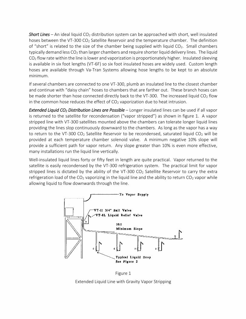
Extended Liquid CO2 Distribution Lines are Possible – Longer insulated lines can be used if all vapor is returned to the satellite for recondensation (“vapor stripped”) as shown in figure 1. A vapor stripped line with VT-300 satellites mounted above the chambers can tolerate longer liquid lines providing the lines slop continuously downward to the chambers. As long as the vapor has a way to return to the VT-300 CO2 Satellite Reservoir to be recondensed, saturated liquid CO2 will be provided at each temperature chamber solenoid valve. A minimum negative 10% slope will provide a sufficient path for vapor return. Any slope greater than 10% is even more effective, many installations run the liquid line vertically.
Well-insulated liquid lines forty or fifty feet in length are quite practical. Vapor returned to the satellite is easily recondensed by the VT-300 refrigeration system. The practical limit for vapor stripped lines is dictated by the ability of the VT-300 CO2 Satellite Reservoir to carry the extra refrigeration load of the CO2 vaporizing in the liquid line and the ability to return CO2 vapor while allowing liquid to flow downwards through the line.
Figure 1
Extended Liquid Line with Gravity Vapor Stripping

A high quality pipe or tube should be used when installing a Liquid CO2 Distribution System. The nominal pressure of the system is 300 PSI. Type ACR copper tubing is well suited for this use in sizes up to 1 ½” diameter. A Liquid Distribution line should be at least 5/8” diameter and lines up to 1” in diameter are often used. Va-Tran Systems recommends that all connections on the liquid line be brazed (not soldered) using a brazing alloy with a minimum 15% silver content. Whenever brazing on a liquid line, an inert cover gas such as N2 or CO2 should be employed to prevent oxidation of the internal surface of the pipe and fittings. This cover gas can be bled through the tubing very slowly. Care must be taken not to allow pressure to build up within the tubing and fittings or the joints formed will leak. Whenever elbows must be used, long radius fittings should be employed providing minimum impedance to liquid or vapor flow.
Installation – It is advisable to install a valve at the liquid outlet of the satellite to allow for service of the liquid line without draining the entire reservoir. A full-Throat ball valve (VT-11) placed vertically will allow vapor to freely return to the satellite. This liquid line supply valve will be used rarely and it is probably desirable to place a note or placard indicating that the valve should remain open at all times. As with all valves on the liquid distribution system, a liquid relief valve (VT-8L) should be installed as a pressure relief device (figure 1). The entire liquid distribution line should be insulated using high quality insulation. VT-6F is a closed cell neoprene pipe insulation available in six-foot lengths providing a minimum 5/8” of insulation. All joints in this insulation should be wrapped with self-adhesive foam as should all valves and other fittings (except VT-8L and vapor riser). If properly insulated, there should not be any place on a liquid line; especially relief valves where ice will form. When affixing the liquid distribution line to supports, do not clamp the insulation, this will decrease its thickness and therefore, it’s ability to keep heat away from the liquid line. Ideally, the line can be suspended on wide supports, alternatively, 2"”plastic pipe can be cut into short sections (2"”to 4"”long) and the insulated pipe run through these sections every 6 to 10 feet.
Liquid Line Protection – Liquid CO2 expands considerably as it warms up and high pressures can develop in the liquid line if liquid CO2 is trapped. Any liquid output valve on the VT-300 should remain open so this cannot happen. Liquid distribution lines should have a relief valve suitable for use with liquid CO2 (VT-8L) placed in each section of liquid line which could be isolated by valves being closed intentionally or inadvertently. The relief valve should be mounted with a tee and extended vertically on an uninsulated riser 9 to 12 inches above the liquid hose or line. The outlet of the relief valve should point downwards and away from anything that might be damaged by a burst of CO2 vapor. Relief valves should never be allowed to become coated with ice or water, a relief valve that has a ball of ice surrounding it is likely to be non-functional. A typical protected liquid drop is shown in Figure 2.
If Valves are Necessary for Each Chamber – When several small chambers are clustered around one VT-300 satellite it is sometimes desirable to put ball valves on the liquid line segments to facilitate the removal of one chamber while others are running. If this is done, every possible segment of the liquid line should be protected with a relief valve. Since lines contain small volumes of liquid, a self-closing relief valve line the VT-8L is suitable.

Figure 2
Liquid CO2 Drop
Connection of Liquid Line to Chamber Solenoid Valve – It is best to install a line filter such as the VT-17 at the solenoid valve input connection to prevent any foreign debris from contaminating the solenoid valve and injector. It is important that all connections be leak-tight since escaping liquid CO2 will excessively chill the solenoid valve. Liquid CO2 leaks will chill the adjacent mass to
–109.7F, which often shrinks other parts and causes more leaks. Throughout the system, Teflon tape should never be used as a pipe sealant but rather a paste type of pipe sealant with Teflon should be used.

677 Anita St., Ste 'A' | Chula Vista, CA. 91911 | 619-423-4555 | Fax 619-423-4604 [email protected] | www.vatran.com

TROUBLE SHOOTING GUIDE FOR VT-300 C02
VAPOR BOOSTING SYSTEMS
1. Provide Serial Number
2. If the unit has been operating properly, has testing load or requirements changed?
3. Check the CO2 vapor supply pressure into unit. Pressure should ideally be 300 PSI and a minimum of 280 PSI. CO2 pressure should be checked at the SR. This can be done with a gauge anywhere in the liquid output line or the vapor input line.
4. Check the voltage to the unit while running. Make sure to check the voltage at the unit and not at the wall outlet. The use of an extension cord is not recommended.
5. Check the compressor fan motor. Is it running? Is the blade slipping?
6. Allow unit to run long enough to fill the reservoir tank. Does the unit shut off after it is full?
7. What is the ambient temperature of the location of the SR? Va-Tran
condensing rates are based on 70 F. Higher ambient temperatures will affect the condensing rate.
No CO2 liquid at SR outlet:
1. Test for liquid CO2 at the output valve by loosening the hose fitting just enough to cause a small leak. If the leak spits dry ice, there is liquid in the line. A hissing discharge without dry ice indicates only vapor is in the output line. Is the liquid line too long or too large causing all liquid to be vaporized? Note: Do not remove the hose and open the output ball valve to test for liquid. This may cause dry ice to form a blockage in the line and the output would only be the CO2 from the plug sublimating. This creates the false assumption that there is no liquid in the reservoir. This may also cause a dangerous situation where the plug can be dislodged and form a projectile.
2. The pressure of the outlet should be equal to the pressure of the inlet. If the outlet pressure is less than the input pressure, there may be a clog in the input supply line or water ice blockage in the SR. To correct this; drain the unit and reverse the flow of the CO2 making the output line the inlet and vice versa.

3. A dirty condenser may affect the performance of the unit. Check to insure airflow to the radiating surfaces is not restricted in any way. Minimum clearance from obstructions is 12”.
4. Check the refrigeration lines inside the cabinet from the compressor into the insulated reservoir while the unit is running. The discharge line should be hot to the touch and the suction line should be cool.
5. Check the pressure controller settings on the compressor. These should match the factory settings that depend upon the serial number and the type of refrigeration media used. Contact Va-Tran for the correct settings based on the serial number of the unit.
6. Do a pull down test prior to any refrigerant work (See VT-300 instruction booklet).
Only after all the above items have been checked should you look into the refrigeration system. Only qualified refrigeration technicians should attempt repairs.
No CO2 liquid at chamber or end of liquid line:
1. If there is no liquid after a successful period of operation, the demand may exceed the condensing rate of the SR. Va-Tran can help calculate the CO2 consumption for your chamber, cold plate or other device.
2. Poor liquid line design – CO2 liquid lines should maintain a minimum 10% downward slope at all times. Check our instruction booklet or website for proper CO2 liquid line design.
3. Chambers, plates or other devices may be located too far from the SR. CO2 liquid lines may be too long and the liquid may be vaporizing in the line. Are the liquid lines properly insulated?
ADDITIONAL QUESTIONS OR INFORMATION:
Should you find you experience problems with your product, please contact our team at Va-Tran Systems. Our fully trained and experienced support staff is on-hand and ready to assist you. In addition, Va-Tran Systems has the experience and capabilities to design and fabricate customized components and specialized systems to assist with application of this equipment.
Thank you for choosing Va-Tran Systems, inc.
677 Anita St., Ste 'A' | Chula Vista, CA. 91911 | 619-423-4555 | Fax 619-423-4604
[email protected] | www.vatran.com