vsd and ss driving atex motors february 2014. 1 introduction to atex 2 atex motor designation 3 vsd...
TRANSCRIPT
VSD AND SSDRIVING ATEX MOTORS
February 2014
1 Introduction to ATEX
2 ATEX motor designation
3 VSD Sample Solutions
4 SS descriptions

EU territory define the use of electrical equipment in potentially explosive atmospheres, within the directives 1992/92/EC and 94/9/EC.
1992/92/EC (ATEX 137) covers the minimum requirements for improving the health and safety protection of workers operating in potentially explosive atmospheres.
94/9/EC (ATEX 95) is intend to allow free trading of equipment and systems for use in a hazardous area without the need for separate testing and documentation.
Introduction to ATEX
ATEX 95Product Directive
94/9/ECRequirements and
certifificates for manufacturers
ATEX 137Workers Protection DIrective
1999/92/ECClassifies zones and states the corresponding product category
*EHSRsProduct Requirements
ZonesRisk analysisCategory 1
Category 2
Category 3
Zone 0/20
Zone 1/21
Zone 2/22
* Essential health and safety requirements

GROUP I ( MINES)
CAT DESCRIPTION
M1 Equipment designed to operate on environments where the explosive atmosphere is present frequently
M2 Equipment that must be powered off if there is any risk of explosion. Explosive atmosphere is present frequently.
CENELEC / IEC Standards provide a criteria which determine the classification of the equipment into groups and categories according to EN / IEC 60079-0:
Depending on the intended use, explosion proof electrical operating equipment is divided into two major groups: Group I: Equipment for coal mines (only special designed motors for mines can be used) Group II: Electrical equipment for use other than mines (surface industry)
GROUP II ( SURFACE INDUSTRY)CAT DESCRIPTION LABEL ZONE
1Equipment with high degree of protection. Explosive atmosphere is present continuously or for long periods of time.
1G (gas)1D (dust)
0 (gas)20 (dust)
2 Equipment with high degree of protection. Explosive atmosphere may occur occasionally..
2G (gas)2D (dust)
1 (gas)21 (dust)
3 Equipment with normal degree of protection. The explosive atmosphere will probably not occur.
3G (gas)3D (dust)
2 (gas)22 (dust)
SUB-GROUP CLASSIFICATION FOR GASES OF EXPLOSURE ATMOSPHERES ( FLAME PROOF MOTORS)GRUPO DESCRIPTION
IIA Acetone, ammonia, benzene, butane, butanol, alcohol butylic, ethane, ethanol, acetate of ethyl, gasoline, hepthanes, hexanes, natural gas, methanol, naphtha, propane, propanol, toluene, esthirene, solvents in general
IIB Acetaldeide, cyclopropane, diethylic ether, ethene, monoxide of carbon
IIC Acetylene, butadiene, oxide of ethene, hydrogen, oxide ofpropylene, gases containing over 30% of hydrogen
Introduction to ATEX

MOTOR DESIGNATION
TYPE DESCRIPTION
tD/DIPProtection by dust ignition prove enclosure according to IEC 61241-1
nA Not sparking. Increased safety in terminal box.
d Explosion Proof (Rugged frame)
de Explosion Proof withIncreased Safety Terminal Box
e Increased Safety. Increased safety in terminal box.
p Pressurized. (Special construction)
ATEX MOTOR DESIGNATION AND AREAS

CLASSES OF TEMPERATURE
The minimum temperature that causes an explosion of a gas, vapour of explosive mixture is called ignition temperature. To avoid any risk of explosion, the motor surface temperature must always stay below the ignition temperature of the explosive mixture.
Class of Temperature (ºC)Maximum motor surface
temperature (C)EN / IEC60079-0 NEC
T1 T1450
T2 T2T2A12BT2CT2D
300280260230215
T3 T3T3AT3BT3C
200180165160
T4 T4T4A
135120
T5 T5100
T6 T685

VSD SAMPLE SOLUTION
The installation of an “Ex e” motor in Zone 1 or 2 is not feasible.
SD700 offers unique features that reduces associated hazard effects in ATEX Zones:o It integrates built-in as standard a dV/dt filter and a CLAMP system that reduce dV/dt rise time
to (500V/µs -800V/µs)o Reduce Peak Voltages at the Motor Windingo Reduce CMC and bearing currents that reduce the risk of winding sparks. o Works at a switching frequency over 4kHz that reduce motor overheatingo Built-in and adjustable motor thermal model.
Solution for “Ex nA” y “Ex tD/DIP” (T3, T4, T5, T6 < 200ºC) y “Ex d, de y p” en Zone 2o ATEX (PT100 or PTC) temperature relay that can be either connected to the drive’s STO or the
upstream disconnector.o Appropiate motor sizing(motor derating)o Switching frequency >3kHzo Declaration of conformity. Power Electronics assumes the responsibility.
Solutions for Ex d y Ex p motors (Zone 1) :o The intrinsic construction of the motors reduce all the risk except the overheating of the motor
housingo That risk can be eliminated by installing:
o ATEX (PT100 o PTC) relay connected to the drive’s input safe stop STO (SD700 only).o ATEX (PT100 o PTC) relay connected to the upstream disconnector.
o Appropiate motor sizing(motor derating)o Switching frequency >3kHz

DERATING CURVE FOR ABB MOTORS
tD/DIP motors derating PWM converters fs>3kHz
nA motors derating PWM converters fs>3kHz
SS DESCRIPTION
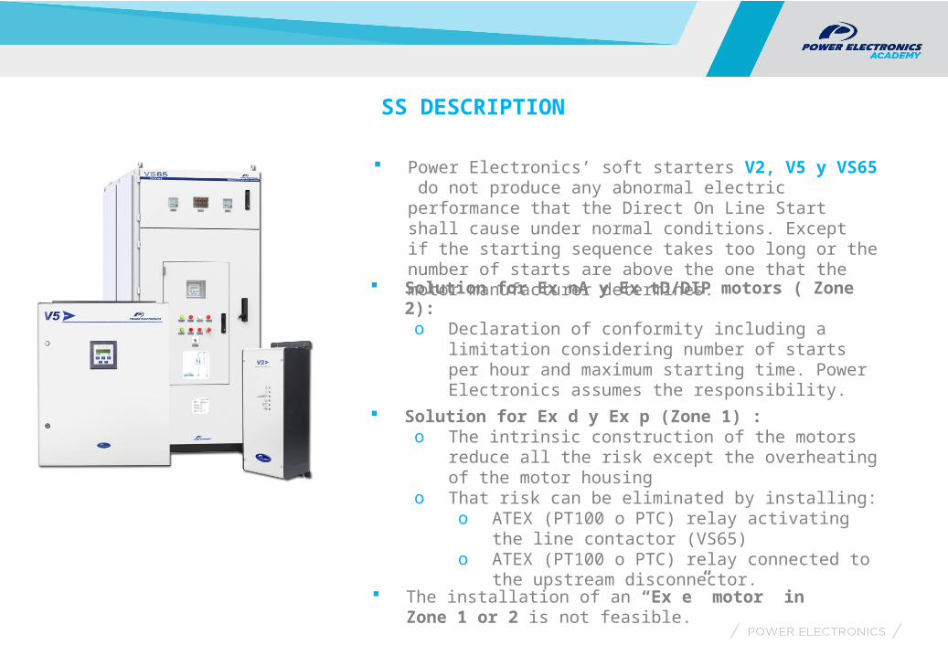
Power Electronics’ soft starters V2, V5 y VS65 do not produce any abnormal electric performance that the Direct On Line Start shall cause under normal conditions. Except if the starting sequence takes too long or the number of starts are above the one that the motor manufacturer determines.
Solution for Ex nA y Ex tD/DIP motors ( Zone 2):o Declaration of conformity including a limitation
considering number of starts per hour and maximum starting time. Power Electronics assumes the responsibility.
Solution for Ex d y Ex p (Zone 1) :o The intrinsic construction of the motors reduce all the
risk except the overheating of the motor housingo That risk can be eliminated by installing:
o ATEX (PT100 o PTC) relay activating the line contactor (VS65)
o ATEX (PT100 o PTC) relay connected to the upstream disconnector.
The installation of an “Ex e” motor in Zone 1 or 2 is not feasible.

POWER ELECTRONICSappreciate your attention
More info:
www.power-electronics.com
More info:
www.power-electronics.com