vsb engineering college, karur department of … · short circuit analysis (symmetrical and...
TRANSCRIPT
1
VSB ENGINEERING COLLEGE, KARUR
DEPARTMENT OF ELECTRICAL AND ELECTRONICS ENGINEERING
ACADEMIC YEAR 2018-2019 (ODD SEMESTER)
III YEAR/V SEMESTER 2 MARK AND 16 MARK QUESTION BANK
S.No SUBJECT
CODE SUBJECT NAME
PAGE
NO
1 EE6501 Power System Analysis 02
2 EE6503 Power Electronics 22
3 ME6701 Power Plant Engineering 34
4 EE6504 Electrical Machines II 53
5 IC6501 Control Systems 70
6 EE6502 Microprocessors and Microcontrollers
89
2
SHORT QUESTIONS AND ANSWERS Year/ Semester/ Class : III/ V/ EEE Subject Code/ Name: EE6501/ Power System Analysis
UNIT – I INTRODUCTION
1. What is the need for system analysis in planning and operation of power system?
2.
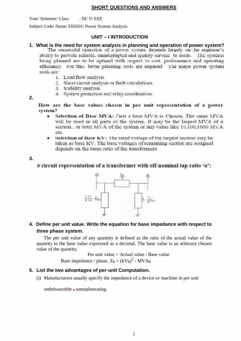
3.
4. Define per unit value. Write the equation for base impedance with respect to
three phase system.
The per unit value of any quantity is defined as the ratio of the actual value of the
quantity to the base value expressed as a decimal. The base value is an arbitrary chosen
value of the quantity. Per unit value = Actual value / Base value
Base impedance / phase, Zb = (kVb)2 / MVAb
5. List the two advantages of per-unit Computation.
(i) Manufacturers usually specify the impedance of a device or machine in per unit
onthebaseofthe.nameplaterating.
3
(ii) The p.u. values of widely different rating machines lie within a narrow range, even though the ohmic values have a very large range.
(iii)The p.u. impedance of circuit element connected by transformers expressed on a
proper base will be same if it is referred to either side of a transformer.
(iv) The p.u. impedance of a three phase transformer is independent of the type of
winding connection. 6. Write the equation for converting the p.u. impedance expressed in one base
to another base.
Zpu,new= Zpu,old x (kVb,old / kVb,new)2 x (MVAb,new / MVAb,old)
7. What are the components of power system?
The components of power system are Generators Power transformers
Transmission lines
Substation transformers
Distribution transformers Loads
8. What is the need for base values?
The components or various sections of power system may operate at different voltage
and power levels. It will be convenient for analysis of power system if the voltage, power,
current and impedance ratings of components of power system are expressed with
reference to a common value called base value. Hence for analysis purpose a base value
is chosen for voltage, power, current and impedance ratings of the components are
expressed as a percent or per unit of the base value.
9. What is bus admittance matrix?
The matrix consisting of the self and mutual admittances of the network of a power
system is called bus admittance matrix.
10. What is single line diagram? Give it advantages.
A single line diagram is diagrammatic representation of power system in which the
components are represented by their symbols and the interconnection between them are
shown by a straight line (even though the system is three phase system).The ratings and
the impedances of the components are also marked on the single line diagram.
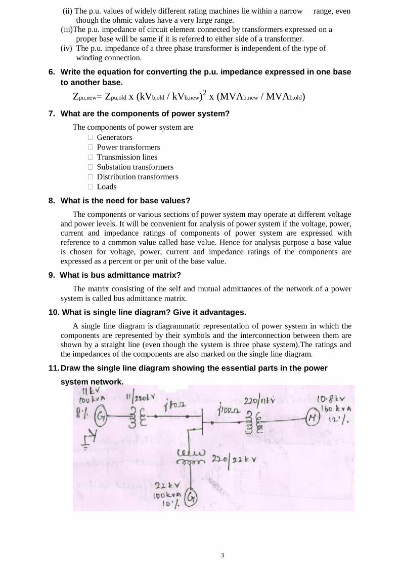
11. Draw the single line diagram showing the essential parts in the power
system network.
4
12. What is a bus?
The meeting points of various components in a power system are called a bus. The
bus is a conductor made of copper or aluminum having negligible resistance. The buses
are considered as points of constant voltage in a power system.
13. What are the applications of Y-bus matrix?
Load flow analysis Optimal load flow analysis Stability analysis.
14. What are the applications of Z-bus matrix? Short Circuit Analysis (symmetrical and unsymmetrical fault analysis).
15. What is the purpose of using single line diagram?
The purpose of the single line diagram is to supply in concise form of the significant
information about the system.
16. What is impedance and reactance diagram?
The impedance diagram is the equivalent circuit of power system in which the various
components of power system are represented by their approximate or simplified
equivalent circuits. The impedance diagram is used for load flow studies.
The reactance diagram is the simplified equivalent circuit of power system in which
the various components of power system are represented by their reactances. The
reactance diagram can be obtained from impedance diagram if all the resistive
components are neglected. The reactance diagram is used for fault calculations.
17. What are the approximations made in impedance diagram?
The following approximations are made while forming impedance
diagram (i)The natural reactance’s are neglected.
(ii)The shunt branches in equivalent circuit of induction motor are neglected
18. What is bus impedance matrix?
The matrix consisting of driving point impedances and transfer
impedances Of the network of a power system is called bus impedance matrix.
19. Write the four ways of adding impedance to an existing system so as to
modify bus impedance matrix.
Adding a branch of impedance Zb from a new bus-p to the reference bus.
Adding a branch of impedance Zb from a new bus-p to an existing bus-q. Adding a branch of impedance Zb from an existing bus-q to the reference bus. Adding a branch of impedance Zb between two existing buses h and q.
20. A generator rated at 30 MVA, 11 kV has a reactance of 20%. Calculate it’s
per unit reactance for a base of 50 MVA and 10 kV.
New p.u.reactance of generator,
Xpu,new= Xpu,old x (kVb,old / kVb,new)2 x (MVAb,new / MVAb,old)
Here, Xpu,old =20%=0.2p.u. , MVAb,old=30MVA, MVAb,new=50MVA,
kVb,old =11KV, kVb,new =50MVA
New p.u.reactance of generator = 0.2 x (11/10)2 x (50/30) =0.403 p.u.
5
21. What are the approximations made in impedance diagram? (Or) What are the factors that need to be omitted for an impedance diagram to reduce it to a reactance diagram?
The neutral reactance are neglected.
Shunt branches in the equivalent circuits of transformer are neglected.
The resistances are neglected.
All static loads and induction motors are neglected.
The capacitances of the transmission lines are neglected.
22. Name the diagonal and off-diagonal elements of bus admittance matrix.
The diagonal elements of bus admittance matrix are called self admittances of the
buses and off-diagonal elements are called mutual admittances of the buses.
UNIT II-POWER FLOW ANALYSIS 1. What is P-Q bus in power flow analysis?
A bus is called PQ-bus or load bus when real and reactive components of power
are specified for the bus. In a load bus the voltage is allowed to vary within
permissible limits.
2. What is the need for power flow or load flow study?
The load flow study of a power system is essential to decide the best operation of
existing system and for planning the future expansion of the system. It is also essential
for designing a new power system.
3. Give the advantages of N-R method.
The N-R method is faster, more reliable and the results are accurate.
Requires less number of iterations for convergence.
The number of iterations are independent of the size of the system(number of buses).
Suitable for large size system.
4. Give the disadvantages of N-R method.
The programming is more complex.
The memory requirement is more.
Computational time per iteration is higher due to large number of calculations per
iteration.
5. Mention any three advantages of N-R method over G-S method.
The N-R method has quadratic convergence characteristic and so convergence
faster than G-S method.
The number of iterations for convergence is independent of the size of the
system in N-R method.
In N-R method the convergence is not affected by the choice of slack bus.
6. What is the need for slack/swing bus in power system?
The slack/swing bus is needed to account for transmission line losses. In a power
system the total power generated will be equal to sum of power consumed by loads
and losses. In a power system only the generated power and load power are specified
for buses. The slack bus is assumed to generate the power required for losses. Since
the losses are unknown the real and reactive power are not specified for slack bus.
They are estimated through the solution of load flow equations.
7. What are the advantages of FDLF method?
o FDLF method is faster, simple to program, more reliable and requires less memory than NR load flow method.
6
8. What are the types of buses? or What are the three classes of buses of a
power system used in power flow analysis?
Load bus or PQ-bus (P and Q are specified)
Generator bus or voltage controlled bus or PV bus (P and V are specified)
Slack bus or swing bus or reference bus (Voltage magnitude and angle are specified)
.
9. Why the load flow studies are important for planning the existing system as well
as its future expansion?
The load flow studies are very important for planning, economic scheduling,
control and operations of existing systems as well as planning its future expansion
depends upon knowing the effect of interconnections, new loads, new generating
stations, or new transmission lines, etc., before they are installed.
10. What is power flow study or load flow study?
The study of various methods of solution to power system network is referred to as load flow
study. The solution provides the voltages at various buses, power flowing in various lines and line-
losses.
11. What is the information that is obtained from load flow study?
The magnitude and phase of bus voltages, real and reactive power flowing in
each line and the line losses.
The load flow solution also gives the initial conditions of the system
when the transient behavior of the system is to be studied.
12. What are the quantities to be specified and to be computed for each class during
power flow solution?
Load bus or PQ-bus (P and Q are specified- Voltage magnitude and angle are to be
obtained)
Generator bus or voltage controlled bus or PV bus (P and V are specified-
Voltage angle and Q are to be obtained)
Slack bus or swing bus or reference bus (Voltage magnitude and angle are
specified- P and Q are to be obtained)
13. What is swing bus (or slack bus)?
A bus is called swing bus (or slack bus) when the magnitude and phase of bus voltage
are specified for it. The swing bus is the reference bus for load flow solution and it is
required for accounting line losses.
Usually one of the generator bus is selected as the swing bus.
14. What are the methods used for the iterative solution of non-linear algebraic equations?
Gauss-Seidal Load Flow Method(GSLF)
Newton-Raphson Load Flow Method(NRLF)
Fast-decoupled Load Flow Method(FDLF)
15. What do you mean by flat voltage start?
In iterative methods of load flow solution, the initial voltages of all buses except slack
bus are assumed as 1+j0 p.u. This is referred to as flat voltage start.
16. What is a bus?
The meeting point of various components in a power system is called as bus.At
some of the buses power is being injected into the network, whereas at other buses it
is being tapped by the system loads.When the generator bus is treated as load bus?
If the reactive power of a generator bus violates the specified limits then the
7
generator bus is treated as load bus.
17. What technique is used to solve load flow problems using Z-bus (Bus impedance
matrix)?
The formulation of load flow problem using Zbus employs Diakoptics techniques
which is actually the piecewise solution of the power system problem by using tearing
off technique.
18. What is PQ bus?
A bus is called PQ bus or load bus when real and reactive components of power
are specified for the bus. In a load bus the voltage is allowed to vary within
permissible limits.
19. What are the four quantities that are associated with each bus in a system?
Real Power
Reactive Power
Voltage magnitude
Phase angle of voltage
UNIT III FAULT ANALYSIS – BALANCED FAULT
1. Write the relative frequency of occurrence of various types of faults.
S.No. Type of fault Relative frequency
of occurrence
1. Three phase fault 5%
2. Double line-to- ground fault
10%
3. Line- to-line fault 15%
4. Single line-to-ground fault
70%
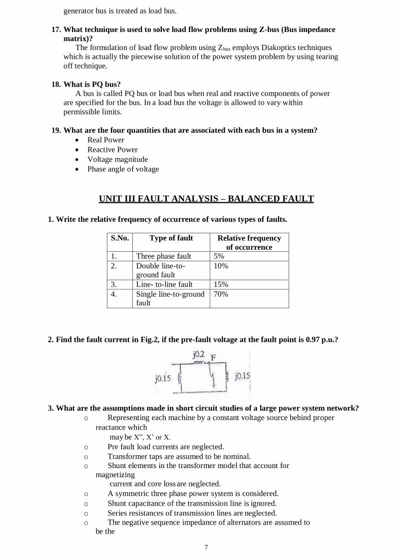
2. Find the fault current in Fig.2, if the pre-fault voltage at the fault point is 0.97 p.u.?
3. What are the assumptions made in short circuit studies of a large power system network?
o Representing each machine by a constant voltage source behind proper
reactance which
may be X”, X’ or X.
o Pre fault load currents are neglected.
o Transformer taps are assumed to be nominal.
o Shunt elements in the transformer model that account for
magnetizing
current and core loss are neglected.
o A symmetric three phase power system is considered.
o Shunt capacitance of the transmission line is ignored.
o Series resistances of transmission lines are neglected.
o The negative sequence impedance of alternators are assumed to be the
8
same as their positive sequence impedance.Z1=Z2
4. What are the reactances used in the analysis of symmetrical faults on the
synchronous machines as its equivalent reactance?
1. Sub transient reactance Xd”
2. Transient reactance Xd’
3. Synchronous reactance Xd 5. What is the reason for Transient during short circuit? The faults or short circuits are associated with sudden change in currents. Most of the components of the power system have inductive property which opposes any sudden change in currents
so the faults (short circuit) are associated with transients.
6. Define short circuit interrupting MVA of a circuit breaker.
The short circuit interrupting MVA of a circuit breaker is the volt-amperes (power)
flowing through it at the moment of opening its contacts due to a fault.It is estimated by
the following equations.
7. Define short circuit capacity of power system (or) fault level.
Short circuit capacity or short circuit MVA or fault level at a bus is defined as the product
of the magnitudes of the pre fault bus voltage and the post fault current.
8. What is meant by doubling effect?
If a symmetrical fault occurs when the voltage wave is going through zero then the
maximum momentary short circuit current will be double the value of maximum
symmetrical short circuit current. This effect is called doubling effect.
9. What is momentary current rating of circuit breaker? How it is estimated.
The momentary current rating is the maximum current that may flow through a circuit
breaker for a short duration. It is estimated by multiplying the symmetrical sub transient
fault current by a factor of 1.6.
10 What is interrupting short circuit current rating of circuit breaker? How it is estimated.
The interrupting short circuit current rating of the circuit breaker is the maximum current
that may flow through it when its contact open due to fault. It is estimated by multiplying
the transient short circuit current by a factor of 1.0 to 1.5.The value of the factor depends
on the speed of the breaker.
11. List the various types of shunt faults.
Line to ground fault
Line to line fault
Double Line to ground fault
Three phase fault
12. What is the need for short circuit analysis?
The short circuit studies are essential in order to design or develop the protective
schemes for various parts of the system. The protective scheme consists of current and
voltage sensing devices, protective relays and circuit breakers. The selection of these
devices mainly depends on various currents that may flow in the fault conditions.
13. List the various types of shunt and series faults.
The various types of shunt faults are
Line to ground fault
Line to line fault
Double Line to ground fault
Three phase fault
The various types of series faults are
9
One open conductor fault
Two open conductor fault
14. List the symmetrical and unsymmetrical faults.
The three phase fault is the only symmetrical fault. All other types of faults are
unsymmetrical faults are unsymmetrical faults.
The various unsymmetrical faults are
Line to ground fault
Line to line fault
Double Line to ground fault
One or two open conductor fault.
15. Name any two methods of reducing short circuit current.
By providing neutral reactance
By introducing a large value of shunt reactance between buses.
16. Define DC off-set current.
The unidirectional transient component of short circuit current is called DC off-set current.
UNIT IV FAULT ANALYSIS – UNBALANCED FAULTS
1. What are the reactances used in the analysis of symmetrical faults on the
synchronous machines as its equivalent reactance?
4. Sub transient reactance Xd”
5. Transient reactance Xd’
6. Synchronous reactance Xd 2. What is the reason for Transient during short circuit? The faults or short circuits are associated with sudden change in currents. Most of the components of the power system have inductive property which opposes any sudden change in currents
so the faults (short circuit) are associated with transients.
3. Define short circuit interrupting MVA of a circuit breaker.
The short circuit interrupting MVA of a circuit breaker is the volt-amperes (power)
flowing through it at the moment of opening its contacts due to a fault.It is estimated by
the following equations.
4. Define short circuit capacity of power system (or) fault level.
Short circuit capacity or short circuit MVA or fault level at a bus is defined as the product
of the magnitudes of the pre fault bus voltage and the post fault current.
5. What is meant by doubling effect?
If a symmetrical fault occurs when the voltage wave is going through zero then the
maximum momentary short circuit current will be double the value of maximum
symmetrical short circuit current. This effect is called doubling effect.
6. What is momentary current rating of circuit breaker? How it is estimated.
The momentary current rating is the maximum current that may flow through a circuit
breaker for a short duration. It is estimated by multiplying the symmetrical sub transient
fault current by a factor of 1.6.
7. What is interrupting short circuit current rating of circuit breaker? How it is estimated.
The interrupting short circuit current rating of the circuit breaker is the maximum current
10
that may flow through it when its contact open due to fault. It is estimated by multiplying
the transient short circuit current by a factor of 1.0 to 1.5.The value of the factor depends
on the speed of the breaker.
8. List the various types of shunt faults.
Line to ground fault
Line to line fault
Double Line to ground fault
Three phase fault
9. What is the need for short circuit analysis?
The short circuit studies are essential in order to design or develop the protective
schemes for various parts of the system. The protective scheme consists of current and
voltage sensing devices, protective relays and circuit breakers. The selection of these
devices mainly depends on various currents that may flow in the fault conditions.
10. List the various types of shunt and series faults.
The various types of shunt faults are
Line to ground fault
Line to line fault
Double Line to ground fault
Three phase fault
The various types of series faults are
One open conductor fault
Two open conductor fault
11. List the symmetrical and unsymmetrical faults.
The three phase fault is the only symmetrical fault. All other types of faults are
unsymmetrical faults are unsymmetrical faults.
The various unsymmetrical faults are
Line to ground fault
Line to line fault
Double Line to ground fault
One or two open conductor fault.
12. Define DC off-set current.
The unidirectional transient component of short circuit current is called DC off-set current.
13. Name any two methods of reducing short circuit current.
By providing neutral reactance
By introducing a large value of shunt reactance between buses.
UNIT V STABILITY ANALYSIS
1. Define infinite bus in a power system.
A bus is called infinite bus if its voltage remains constant and does not altered by any changes
in generator excitation.
11
2. Define stability.
The stability of a system is defined as the ability of power system to return to stable
(synchronous) operation when it is subjected to a disturbance.
3. Define steady state and transient state stability.
The steady state stability of a system is defined as the ability of power system to remain stable
(without loosing synchronism) for small disturbances.
The transient stability of a system is defined as the ability of power system to remain stable
(without loosing synchronism) for large disturbances.
4. Define power angle.
The power angle (or torque angle) is defined as the angular displacement of the rotor from
synchronously rotating reference frame.
5. What is power system stability?
Power system stability is the property of the system that enables it to remain in a state of operating equilibrium under normal operating conditions and to regain an acceptable state of
equilibrium after being subjected to a disturbance.
6. State equal area criterion.
The equal area criterion for stability states that the system is stable if the area under Pa-
curve
reduces to zero at some value of .This is possible if the positive (accelerating) area under Pa-
curve is equal to the negative (decelerating) area under Pa-
curve for a finite change in .Hence
the
stability criterion is called equal area criterion.
7. Write the concept of critical clearing angle.
The critical clearing angle, cc is the maximum allowable change in the power angle before clearing the fault, without loss of synchronism. The time corresponding to this angle is called critical clearing time, tcc.
8. Define steady state stability limit.
The steady state stability limit is the maximum power that can be transmitted by
a machine (or transmitting system) to a receiving system without loss of synchronism. In
steady state the power transferred by synchronous machine (or power system) is always
less than the steady state stability limit.
9. State equal area criterion. The equal area criterion for stability states that the system is stable if the area under Pa- Curve reduces to zero at some value of . This is possible only if the positive (accelerating) area under Pa- curve is equal to the negative (deceleration) area under Pa- curve for a finite change in .Hence this stability criterion is called equal area criterion.
10. In a 3-machine system having ratings S1 S2 and S3 and inertia constants M1 M2
and M3, what is inertia constant M and H of the equivalent system?
Meq=M1S1/Sb+ M2S2/Sb+ M3S3/Sb
Where, S1, S2, S3=MVA ratings of machines 1, 2, 3 respectively. Sb =Base MVA or MVA rating of system.
Heq= M eq�f
Sb
12
11. List any two methods of improving the transient stability limit of power system.
The following are the methods used to improve the transient stability of a system. • Increase of system voltage and use of AVR (Automatic Voltage Regulation). • Use of high speed excitation systems.
• Reduction in system transfer reactance.
• Use of high speed reclosing breakers. 12. Define swing curve. What is the use of swing curve?
The swing curve is the plot or graph between the power angle and time t. It is usually plotted for a transient state to study the nature of variation in for a sudden large
disturbance.
From the nature of variation of the stability of the system for any disturbance can be determined.
13. Write the power-angle equation of a synchronous machine connected to an infinite
bus and also the expression for maximum power transferable to the bus.
The power-angle equation of a machine connected to an infinite bus is given by, Pe � Pmax sin
Where, Pmax � E V / X 1. =Magnitude of internal E.M.F of generator. 2. = Magnitude of infinite bus voltage. =Transfer reactance between generator and infinite bus.
=Power angle or torque angle.
14. Define critical clearing time and critical clearing angle.
The critical clearing angle, cc is the maximum allowable change in the power angle before clearing
the fault, without loss of synchronism. The time corresponding to this angle is called critical
clearing time, tcc.The critical clearing time, tcc can be defined as the maximum time delay that can be allowed to clear a fault without loss of synchronism.
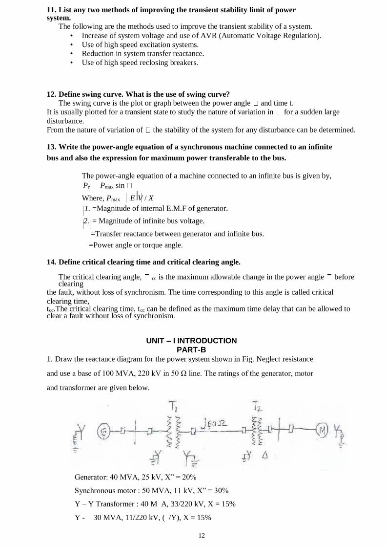
UNIT – I INTRODUCTION PART-B 1. Draw the reactance diagram for the power system shown in Fig. Neglect resistance
and use a base of 100 MVA, 220 kV in 50 Ω line. The ratings of the generator, motor
and transformer are given below.
Generator: 40 MVA, 25 kV, X” = 20%
Synchronous motor : 50 MVA, 11 kV, X” = 30%
Y – Y Transformer : 40 M A, 33/220 kV, X = 15%
Y - 30 MVA, 11/220 kV, ( /Y), X = 15%
13
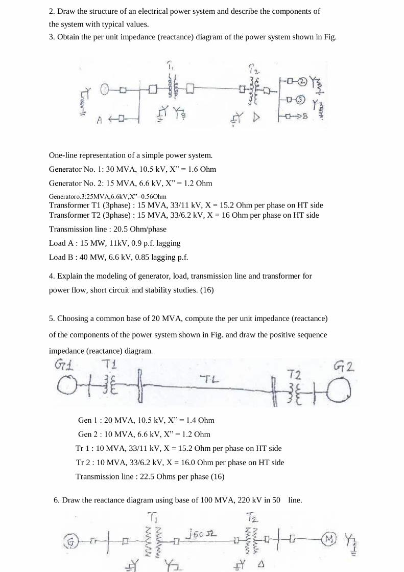
2. Draw the structure of an electrical power system and describe the components of
the system with typical values.
3. Obtain the per unit impedance (reactance) diagram of the power system shown in Fig.
One-line representation of a simple power system.
Generator No. 1: 30 MVA, 10.5 kV, X” = 1.6 Ohm
Generator No. 2: 15 MVA, 6.6 kV, X” = 1.2 Ohm
Generatoro.3:25MVA,6.6kV,X”=0.56Ohm
Transformer T1 (3phase) : 15 MVA, 33/11 kV, X = 15.2 Ohm per phase on HT side Transformer T2 (3phase) : 15 MVA, 33/6.2 kV, X = 16 Ohm per phase on HT side
Transmission line : 20.5 Ohm/phase
Load A : 15 MW, 11kV, 0.9 p.f. lagging
Load B : 40 MW, 6.6 kV, 0.85 lagging p.f.
4. Explain the modeling of generator, load, transmission line and transformer for
power flow, short circuit and stability studies. (16)
5. Choosing a common base of 20 MVA, compute the per unit impedance (reactance)
of the components of the power system shown in Fig. and draw the positive sequence
impedance (reactance) diagram.
Gen 1 : 20 MVA, 10.5 kV, X” = 1.4 Ohm
Gen 2 : 10 MVA, 6.6 kV, X” = 1.2 Ohm
Tr 1 : 10 MVA, 33/11 kV, X = 15.2 Ohm per phase on HT side
Tr 2 : 10 MVA, 33/6.2 kV, X = 16.0 Ohm per phase on HT side
Transmission line : 22.5 Ohms per phase (16)
6. Draw the reactance diagram using base of 100 MVA, 220 kV in 50 line.
14
Generator : 40 MVA, 25 kV,, X” = 20%
Synchronous motor : 50 MVA, 11 kv, X” = 30%
Star-Star transformer : 40 MVA, 33/220 kV, X = 15%
Star-delta transformer : 30 MVA, 11/220 kV, X = 15%. (16)
7. (i) What are the step by step procedures to be followed to find the per-unit
impedance diagram of a power system? (4)
(ii) Draw the structure of an electrical power system and describe the
components of the system with typical values. (12)
8. Write short notes on:
(i) Single line diagram (5)
(ii) Change of base. (5)
(iii)Reactanceofsynchronosmachies.(6)
9. A 120 MVA, 19.5 kV Generator has a synchronous reactance of 0.15 p.u
and it is connected to a transmission line through a Transformer rated 150
MVA, 230/18 kV (star/delta) with X = 0.1 p.u.
(i) Calculate the p.u reactance by taking generator rating as base values
(5)
(ii) Calculate the p.u reactance by taking transformer rating as base
values. (5) (iii) Calculate the p.u reactance for a base value of 100 MVA
and 220 kV on H.T
side of transformer. (6)
15
UNIT II-POWER FLOW ANALYSIS
PART-B
1. Derive load flow algorithm using Gauss – Seidel method with flow chart and discuss
the advantages of the method. (16)
2. Derive load flow algorithm using Newton-Raphson method with flow chart and state
the importance of the method. (16)
3. Explain clearly the algorithmic steps for solving load flow equation using Newton –
Raphson method (polar form) when the system contains all types of buses. Assume that
the generators at the P-V buses have adequate Q Limits. (16)
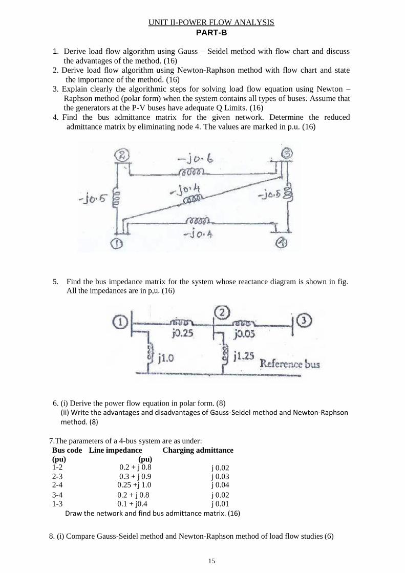
4. Find the bus admittance matrix for the given network. Determine the reduced
admittance matrix by eliminating node 4. The values are marked in p.u. (16)
5. Find the bus impedance matrix for the system whose reactance diagram is shown in fig.
All the impedances are in p,u. (16)
6. (i) Derive the power flow equation in polar form. (8)
(ii) Write the advantages and disadvantages of Gauss-Seidel method and Newton-Raphson method. (8)
7.The parameters of a 4-bus system are as under:
Draw the network and find bus admittance matrix. (16)
8. (i) Compare Gauss-Seidel method and Newton-Raphson method of load flow studies (6)
Bus code
(pu) 1-2
Line impedance
(pu) 0.2 + j 0.8
Charging admittance
j 0.02
2-3 0.3 + j 0.9 j 0.03 2-4 0.25 +j 1.0 j 0.04
3-4 0.2 + j 0.8 j 0.02 1-3 0.1 + j0.4 j 0.01
16
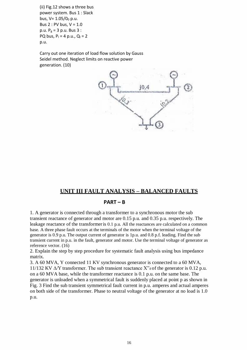
(ii) Fig.12 shows a three bus power system. Bus 1 : Slack bus, V= 1.05/00 p.u. Bus 2 : PV bus, V = 1.0 p.u. Pg = 3 p.u. Bus 3 : PQ bus, Pl = 4 p.u., Ql = 2 p.u.
Carry out one iteration of load flow solution by Gauss Seidel method. Neglect limits on reactive power generation. (10)
UNIT III FAULT ANALYSIS – BALANCED FAULTS
PART – B
1. A generator is connected through a transformer to a synchronous motor the sub
transient reactance of generator and motor are 0.15 p.u. and 0.35 p.u. respectively. The
leakage reactance of the transformer is 0.1 p.u. All the reactances are calculated on a common
base. A three phase fault occurs at the terminals of the motor when the terminal voltage of the generator is 0.9 p.u. The output current of generator is 1p.u. and 0.8 p.f. leading. Find the sub
transient current in p.u. in the fault, generator and motor. Use the terminal voltage of generator as
reference vector. (16)
2. Explain the step by step procedure for systematic fault analysis using bus impedance
matrix.
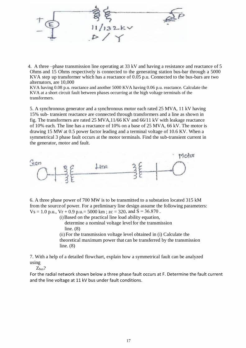
3. A 60 MVA, Y connected 11 KV synchronous generator is connected to a 60 MVA,
11/132 KV Δ/Y transformer. The sub transient reactance X”d of the generator is 0.12 p.u.
on a 60 MVA base, while the transformer reactance is 0.1 p.u. on the same base. The
generator is unloaded when a symmetrical fault is suddenly placed at point p as shown in
Fig. 3 Find the sub transient symmetrical fault current in p.u. amperes and actual amperes
on both side of the transformer. Phase to neutral voltage of the generator at no load is 1.0
p.u.
17
4. A three –phase transmission line operating at 33 kV and having a resistance and reactance of 5 Ohms and 15 Ohms respectively is connected to the generating station bus-bar through a 5000 KVA step up transformer which has a reactance of 0.05 p.u. Connected to the bus-bars are two alternators, are 10,000 KVA having 0.08 p.u. reactance and another 5000 KVA having 0.06 p.u. reactance. Calculate the KVA at a short circuit fault between phases occurring at the high voltage terminals of the
transformers.
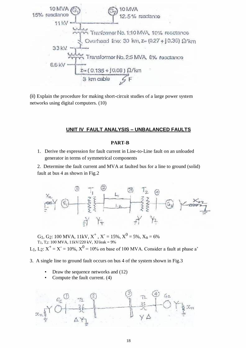
5. A synchronous generator and a synchronous motor each rated 25 MVA, 11 kV having
15% sub- transient reactance are connected through transformers and a line as shown in
fig. The transformers are rated 25 MVA,11/66 KV and 66/11 kV with leakage reactance
of 10% each. The line has a reactance of 10% on a base of 25 MVA, 66 kV. The motor is
drawing 15 MW at 0.5 power factor leading and a terminal voltage of 10.6 KV. When a
symmetrical 3 phase fault occurs at the motor terminals. Find the sub-transient current in
the generator, motor and fault.
6. A three phase power of 700 MW is to be transmitted to a substation located 315 kM
from the source of power. For a preliminary line design assume the following parameters:
Vs = 1.0 p.u., Vr + 0.9 p.u.= 5000 km ; zc = 320, and Ś = 36.870 . (i) Based on the practical line load ability equation,
determine a nominal voltage level for the transmission
line. (8)
(ii) For the transmission voltage level obtained in (i) Calculate the
theoretical maximum power that can be transferred by the transmission
line. (8)
7. With a help of a detailed flowchart, explain how a symmetrical fault can be analyzed
using
Zbus?
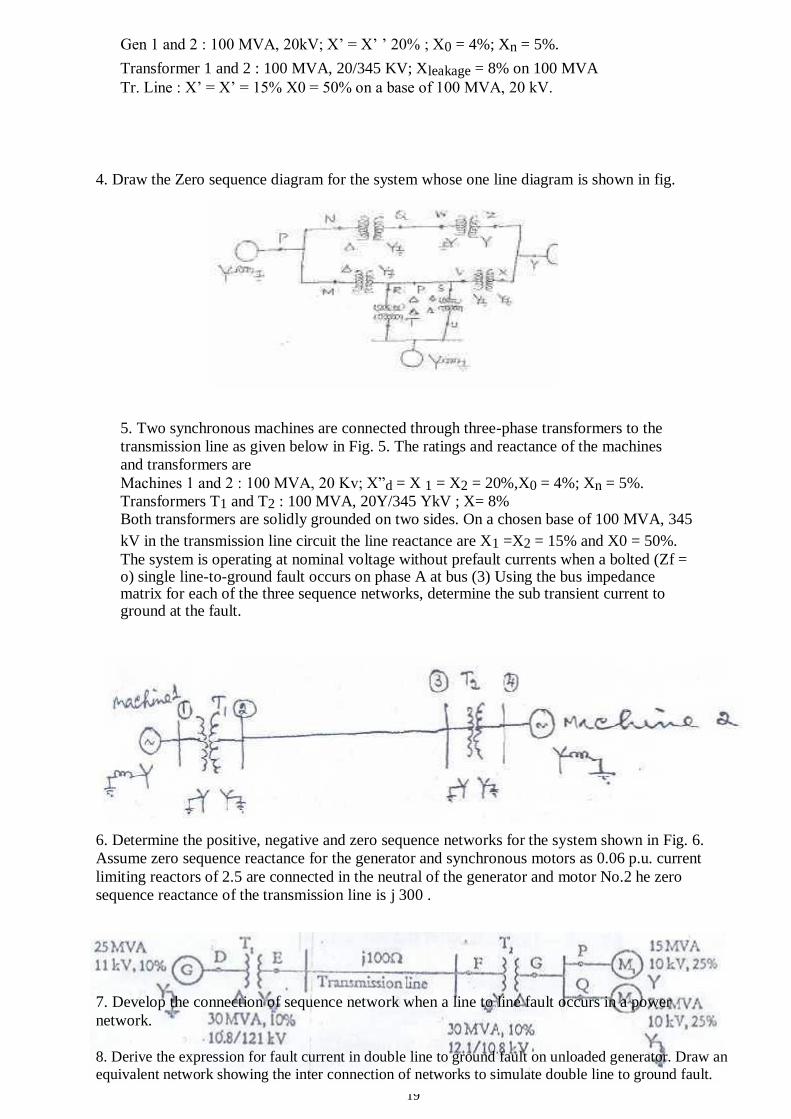
For the radial network shown below a three phase fault occurs at F. Determine the fault current and the line voltage at 11 kV bus under fault conditions.
18
(ii) Explain the procedure for making short-circuit studies of a large power system
networks using digital computers. (10)
UNIT IV FAULT ANALYSIS – UNBALANCED FAULTS
PART-B
1. Derive the expression for fault current in Line-to-Line fault on an unloaded
generator in terms of symmetrical components
2. Determine the fault current and MVA at faulted bus for a line to ground (solid)
fault at bus 4 as shown in Fig.2
G1, G2: 100 MVA, 11kV, X+ , X
- = 15%, X
0 = 5%, Xn = 6%
T1, T2: 100 MVA, 11kV/220 kV, Xl\leak = 9%
L1, L2: X+ = X
- = 10%, X
0 = 10% on base of 100 MVA. Consider a fault at phase a’
3. A single line to ground fault occurs on bus 4 of the system shown in Fig.3
• Draw the sequence networks and (12)
• Compute the fault current. (4)
19
Gen 1 and 2 : 100 MVA, 20kV; X’ = X’ ’ 20% ; X0 = 4%; Xn = 5%.
Transformer 1 and 2 : 100 MVA, 20/345 KV; Xleakage = 8% on 100 MVA Tr. Line : X’ = X’ = 15% X0 = 50% on a base of 100 MVA, 20 kV.
4. Draw the Zero sequence diagram for the system whose one line diagram is shown in fig.
5. Two synchronous machines are connected through three-phase transformers to the
transmission line as given below in Fig. 5. The ratings and reactance of the machines
and transformers are
Machines 1 and 2 : 100 MVA, 20 Kv; X”d = X 1 = X2 = 20%,X0 = 4%; Xn = 5%.
Transformers T1 and T2 : 100 MVA, 20Y/345 YkV ; X= 8% Both transformers are solidly grounded on two sides. On a chosen base of 100 MVA, 345
kV in the transmission line circuit the line reactance are X1 =X2 = 15% and X0 = 50%.
The system is operating at nominal voltage without prefault currents when a bolted (Zf = o) single line-to-ground fault occurs on phase A at bus (3) Using the bus impedance matrix for each of the three sequence networks, determine the sub transient current to ground at the fault.
6. Determine the positive, negative and zero sequence networks for the system shown in Fig. 6.
Assume zero sequence reactance for the generator and synchronous motors as 0.06 p.u. current
limiting reactors of 2.5 are connected in the neutral of the generator and motor No.2 he zero
sequence reactance of the transmission line is j 300 .
7. Develop the connection of sequence network when a line to line fault occurs in a power
network.
8. Derive the expression for fault current in double line to ground fault on unloaded generator. Draw an
equivalent network showing the inter connection of networks to simulate double line to ground fault.
20
UNIT V STABILITY ANALYSIS
PART-B
1. Derive swing equation used for stability studies in power system.
2.
Explain the modified Euler method of analyzing multi machine power system for stability with
a neat flow chart.
3. (i)Derive swing equation for a synchronous machine.
(ii)A 50 Hz generator is delivering 50% of the power that it is capable of delivering through a
transmission line to an infinite bus. A fault occurs that increases the reactance between the
generator
and the infinite bus to 500% of the value before the fault. When the fault is isolated, the
maximum
power that can be delivered is 75% of the original maximum value. Determine the critical
clearing
angle for the condition described.
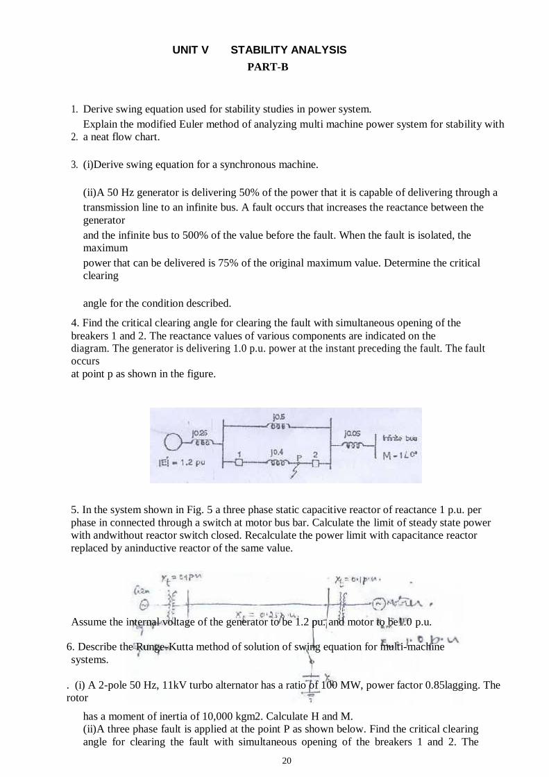
4. Find the critical clearing angle for clearing the fault with simultaneous opening of the
breakers 1 and 2. The reactance values of various components are indicated on the diagram. The generator is delivering 1.0 p.u. power at the instant preceding the fault. The fault
occurs
at point p as shown in the figure.
5. In the system shown in Fig. 5 a three phase static capacitive reactor of reactance 1 p.u. per
phase in connected through a switch at motor bus bar. Calculate the limit of steady state power
with andwithout reactor switch closed. Recalculate the power limit with capacitance reactor
replaced by aninductive reactor of the same value.
Assume the internal voltage of the generator to be 1.2 pu. and motor to be1.0 p.u.
6. Describe the Runge-Kutta method of solution of swing equation for multi-machine
systems.
. (i) A 2-pole 50 Hz, 11kV turbo alternator has a ratio of 100 MW, power factor 0.85lagging. The
rotor
has a moment of inertia of 10,000 kgm2. Calculate H and M.
(ii)A three phase fault is applied at the point P as shown below. Find the critical clearing
angle for clearing the fault with simultaneous opening of the breakers 1 and 2. The
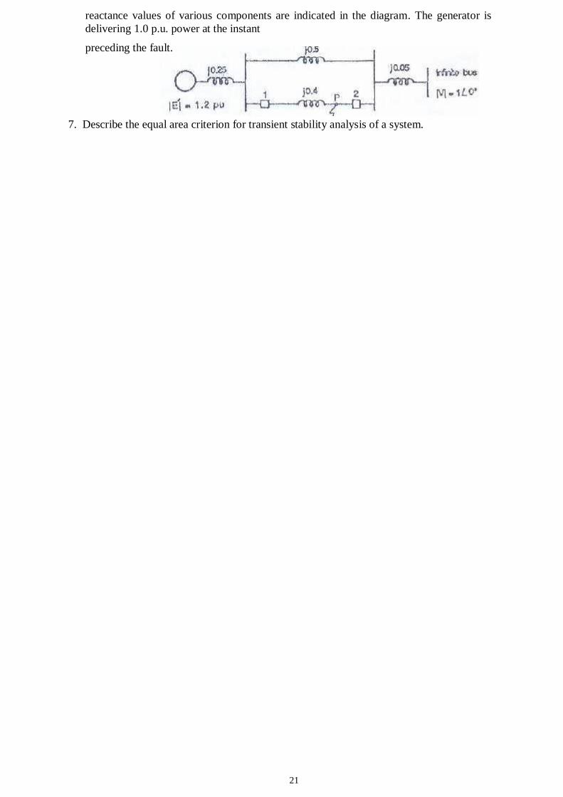
21
reactance values of various components are indicated in the diagram. The generator is
delivering 1.0 p.u. power at the instant
preceding the fault.
7. Describe the equal area criterion for transient stability analysis of a system.
22
EE 6503 - POWER ELECTRONICS
TWO MARK QUESTIONS WITH ANSWER
UNIT-I
POWER SEMI-CONDUCTOR DEVICES
1. Why IGBT is very popular nowadays?
i) Lower hate requirements
ii) Lower switching losses
iii) Smaller snubbed circuit requirements
2. What are the different methods to turn on the thyristor?
i) Forward voltage triggering
ii) Gate triggering
iii) dv/dt triggering
iv) Temperature triggering
v) Light triggering
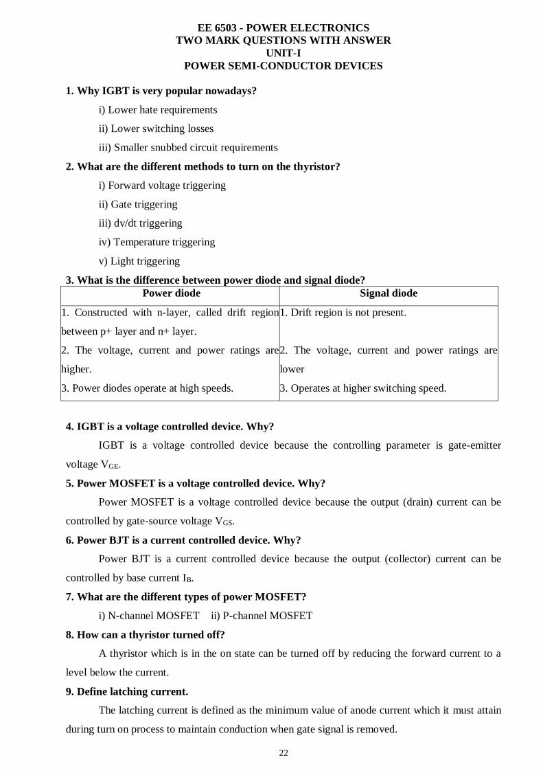
3. What is the difference between power diode and signal diode?
Power diode Signal diode
1. Constructed with n-layer, called drift region
between p+ layer and n+ layer.
2. The voltage, current and power ratings are
higher.
3. Power diodes operate at high speeds.
1. Drift region is not present.
2. The voltage, current and power ratings are
lower
3. Operates at higher switching speed.
4. IGBT is a voltage controlled device. Why?
IGBT is a voltage controlled device because the controlling parameter is gate-emitter
voltage VGE.
5. Power MOSFET is a voltage controlled device. Why?
Power MOSFET is a voltage controlled device because the output (drain) current can be
controlled by gate-source voltage VGS.
6. Power BJT is a current controlled device. Why?
Power BJT is a current controlled device because the output (collector) current can be
controlled by base current IB.
7. What are the different types of power MOSFET?
i) N-channel MOSFET ii) P-channel MOSFET
8. How can a thyristor turned off?
A thyristor which is in the on state can be turned off by reducing the forward current to a
level below the current.
9. Define latching current.
The latching current is defined as the minimum value of anode current which it must attain
during turn on process to maintain conduction when gate signal is removed.
23
10. Define holding current.
The holding current is defined as the minimum value of anode current below which it must
fall to for turning off the thyristor.
11. What is a snubber circuit?
It consists of a series combination of a resistor and a capacitor in parallel with the
thyristors. It is mainly used for dv / dt protection.
12. What losses occur in a thyristor during working conditions?
i) Forward conduction losses
ii) Loss due to leakage current during forward and reverse blocking.
iii) Switching losses at turn-on and turn-off.
iv) Gate triggering loss.
13. Define hard-driving or over-driving.
When gate current is several times higher than the minimum gate current required, a
thyristor is said to be hard-fired or over-driven. Hard-firing of a thyristor reduces its turn-on time
and enhances its di/dt capability.
14. Define circuit turn off time.
It is defined as the time during which a reverse voltage is applied across the thyristor
during its commutation process.
15. Why circuit turn off time should be greater than the thyristor turn-off time?
Circuit turn off time should be greater than the thyristor turn-off time for reliable turn-off,
otherwise the device may turn-on at an undesired instant, a process called commutation failure.
16. Why MOSFETs are not preferred for low frequency applications?
MOSFETs are majority carrier devices. At low frequency the internal losses are very high,
hence MOSFETs are not preferred for low frequency
17. What is the turn-off time for converter grade SCRs and inverter grade SCRs?
Turn-off time for converter grade SCRs is 50 – 100 ms turn-off time for converter grade
SCRs and inverter grade SCRs and for inverter grade SCRs is 3 – 50 ms.
18. What are the advantages of GTO over SCR?
i) Elimination of commutation of commutating components in forced commutation,
resulting in reduction in cost, weight and volume.
ii) Faster turn-off, permitting high switching frequencies.
iii) Reduction in acoustic noise and electromagnetic noise due to elimination of
commutation chokes.
iv) Improved efficiency of the converters.
19. What is reverse recovery time?
24
It is the time for which negative current flows through the SCR. During this period, all the
carriers inside the SCR are removed and junctions J1 and J3 achieve their forward blocking
state. At the end of reverse recovery time, anode current becomes zero.
20. In Triacs which of the mode the sensitivity of gate is high?
In Triac sensitivity of gate is high in I+ (MT2 positive, gate current and voltage positive)
and III- (MT2 negative, gate current and voltage negative).
UNIT-II
PHASE CONTROLLED CONVERTERS
1. What is the function of freewheeling diodes in controlled rectifier?
It serves two processes
i) It prevents the output voltage from becoming negative.
ii) The load current is transferred from the main thyristors to the freewheeling diode there
by allowing all of its thyristors to regain their blocking states.
2. What are the advantages of freewheeling diodes in a controlled in a controlled rectifier?
i) Input power factor is improved.
ii) Load current waveform is improved and thus the load performance is better.
3. What is meant by delay angle?
The delay angle is defined as the angle between the zero crossing of the input voltage and
the instant the thyristor is fired.
4. What are the advantages of single phase bridge converter over single phase mid-point
Converter?
i) SCRs are subjected to a peak-inverse voltage of 2Vm in a fully controlled bridge
rectifier. Hence for same voltage and current ratings of SCRs, power handled by mid-point
configuration is about.
ii) In mid-point converter, each secondary winding should be able to supply the load
power. As such, the transformer rating in mid-point converter is double the load rating.
5. What is commutation angle or overlap angle?
The commutation period when outgoing and incoming thyristors are conducting is known
as overlap period. The angular period, when both devices share conduction is known as the
commutation angle or overlap angle.
6. What are the different methods of firing circuits for line commutated converter?
i) UJT firing circuit.
ii) The cosine wave crossing pulse timing control.
iii) Digital firing schemes.
7. Give an expression for average voltage of single phase semiconverters?
Average output voltage(Vdc) is given by
Vdc = (Vm / π) (1 + cosα)
8. What is meant by input power factor in controlled rectifier?
25
The input power factor is defined as the ratio of the total mean input power to the total
RMS Input volt-amperes.pf = (V1I1cosφ1) / (Vrms x Irms) where V1= phase voltage, I1 =
fundamental component of the supply current, φ1 = input displacement angle, Irms = supply rms
current.
9. What are the advantages of six pulse converter?
i) Commutation is made simple.
ii) Distortion on the ac side is reduced due to the reduction in lower order harmonics.
iii) Inductance reduced in series is considerably reduced
10. What is meant by commutation?
It is the process of changing the direction of current flow in a particular path of the
circuit. This process is used in thyristors for turning it off.
11. What are the types of commutation?
i) Natural commutation.
ii) Forced commutation
12. What is meant by natural commutation?
Here the current flowing through the thyristor goes through a natural zero and enable the
thyristor to turn off.
13. What is meant by forced commutation?
In this commutation, the current flowing through the thyristor is forced to become zero by
external circuitry.
14. What is meant by phase controlled rectifier?
Phase controlled rectifier converts fixed ac voltage into variable dc voltage.
15. Mention some of the applications of controlled rectifier?
i) Steel rolling mills, printing press, textile mills and paper mills employing dc motor
drives.
ii) DC traction
iii) Electro chemical and electro-metallurgical process
iv) Portable hand tool drives
v) HVDC transmission system
16. What is the displacement factor?
Displacement factor is equal to power factor for linear loads with sinusoidal voltages and
currents.
17. What is the turns-ratio of a transformer?
It is defined as the number of the turns on its secondary divided by the number of turns on
its primary. Vs/Vp=Ns/Np
18. What is the difference between rectifier and converters?
Rectifier is a system which converts AC voltage in to DC voltage. Converter is a system
which contains both inverter and rectifier.
26
19. What are the performance parameters of a rectifier?
Rectifiers have two parameters
(1) Maximum forward current.
(2) Maximum reverse voltage
20. What is the purpose of the form factor of the rectifier?
The purpose of the form factor which measure of the shape of output voltage.
FF=Vrms / Vdc.
UNIT-III
DC TO DC CONVERTER
1. What is meant by dc chopper?
A dc chopper is a high speed static switch used to obtain variable dc voltage from a
constant dc voltage.
2. What are the applications of dc chopper?
i) Battery operated vehicles
ii) Traction motor control in electric traction
iii) Trolley cars
iv) Marine hoists
v) Mine haulers
vi) Electric braking.
3. What are the advantages of dc chopper?
i) High efficiency
ii) Smooth acceleration
iii) Fast dynamic response
iv) Regeneration
4. What is meant by step-up and step-down chopper?
In a step- down chopper or Buck converter, the average output voltage is less than the input
voltage. In a step- up chopper or Boost converter, the average output voltage is more than the input
voltage.
5. What is meant by duty-cycle?
Duty cycle is defined as the ratio of the on time of the chopper to the total time period
of the chopper. It is denoted by α.
6. What are the two types of control strategies?
i) Time Ratio Control (TRC)
ii) Current Limit Control method (CLC)
7. What is meant by Time Ratio Control?
In Time Ratio Control, the value of Ton / T is varied in order to change the average output
voltage.
27
8. What are the two types of Time Ratio Control?
i) Constant frequency control
ii) Variable frequency control
9. What is meant by FM control in a dc chopper?
In frequency modulation control, the chopping frequency f (or the chopping period T) is
varied. Here two controls are possible. i) On-time Ton is kept constant, ii) Off period Toff is
kept constant.
10. What is meant by PWM control in dc chopper?
In this control method, the on time Ton is varied but chopping frequency is kept constant.
The width of the pulse is varied and hence this type of control is known as Pulse Width
Modulation (PWM).
11. Write down the expression for the average output voltage for step down and step up
chopper?
Average output voltage for step down chopper is Vo=αVs. Average output voltage for step
up chopper is Vo =αVs x [1/ (1-α)].
12. What are the different types of chopper with respect to commutation process?
i) Voltage commutated chopper.
ii) Current commutated chopper.
iii) Load commutated chopper.
13. What is meant by voltage commutation?
In this process, a charged capacitor momentarily reverse biases the conducting thyristor and
turn it off.
14. What is meant by current commutation?
In this process, a current pulse is made to flow in the reverse direction through the
conducting thyristor and when the net thyristor current becomes zero, it is turned off.
15. What is meant by load commutation?
In this process, the load current flowing through the thyristor either becomes zero or is
transferred to another device from the conducting thyristor.
16. What are the advantages of current commutated chopper?
i) The capacitor always remains charged with the correct polarity.
ii) Commutation is reliable as load current is less than the peak commutation current ICP.
iii) The auxiliary thyristor TA is naturally commutated as its current passes through zero
value.
17. What are the advantages of load commutated chopper?
i) Commutating inductor is not required.
ii) It is capable of commutating any amount of load current.
iii) It can work at high frequencies in the order of kHz.
iv) Filtering requirements are minimal.
18. What are the disadvantages of load commutated chopper?
28
i) For high power applications, efficiency becomes very low because of high switching
losses at high operating frequencies.
ii) Freewheeling diode is subjected to twice the supply voltage.
iii) Peak load voltage is equal to twice the supply voltage.
iv) The commutating capacitor has to carry full load current at a frequency of
half chopping Frequency.
v) One thyristor pair should be turned-on only when the other pair is commutated. This
can be realized by sensing the capacitor current that is alternating.
19. Write down the expression for average output voltage for step down chopper?
Average output voltage for step down chopper is Vo=αVs,
where, α is the duty cycle
20. What is SMPS?
SMPS means switch mode power supply. It is an electronic device which converts or
switches required dc voltage to the appliances.
UNIT-V
AC TO AC CONVERTERS
1. What does ac voltage controller mean?
It is device which converts fixed alternating voltage into a variable voltage without change
in frequency.
2. What are the applications of ac voltage controllers?
i) Domestic and industrial heating
ii) Lighting control
iii) Speed control of single phase and three phase ac motors
iv) Transformer tap changing
3. What are the advantages of ac voltage controllers?
i) High efficiency
ii) Flexibility in control
iii) Less maintenance
4. What are the disadvantages of ac voltage controllers?
The main drawback is the introduction of harmonics in the supply current and the load
voltage waveforms particularly at low output voltages.
5. What are the two methods of control in ac voltage controllers?
i) ON-OFF control
ii) Phase control.
6. What is the difference between ON-OFF control and phase control?
ON-OFF control: In this method, the thyristors are employed as switches to connect the
load circuit to the source for a few cycles of the load voltage and disconnect it for another few
29
cycles. Phase control: In this method, thyristor switches connect the load to the ac source for a
portion of each half cycle of input voltage.
7. What is the advantage of ON-OFF control?
Due to zero-voltage and zero current switching of thyristors, the harmonics generated by
the switching action are reduced.
8. What is the disadvantage of ON-OFF control?
This type of control is applicable in systems that have high mechanical inertia and high
thermal time constant.
9. What is the duty cycle in ON-OFF control method?
Duty cycle K = n/ (n + m), where n = number of ON cycles, m = number of OFF cycles.
10. What is meant by unidirectional or half-wave ac voltage controller?
In unidirectional controller the power flow is controlled only during the positive half-cycle
of the input voltage.
11. What are the disadvantages of unidirectional or half-wave ac voltage controller?
i) Due to the presence of diode on the circuit, the control range is limited and the effective
RMS output voltage can be varied between 70.7% and 100%.
ii) The input current and output voltage are asymmetrical and contain a dc component. If
there is an input transformer, saturation problem will occur
iii) It is only used for low power resistive load.
12. What is meant by bidirectional or half-wave ac voltage controller?
In bidirectional controller the power flow is controlled during both cycles of the input
voltage.
13. What type of gating signal is used in single phase ac voltage controller with RL load?
High frequency carrier gating signal is used for single phase ac voltage controller with RL
load.
14. What are the disadvantages of continuous gating signal?
i) More heating of the SCR gate.
ii) Increases the size of pulse transformer.
15. What is meant by high frequency carrier gating?
Thyristor is turned on by using a train of pulses from a to p. This type of signal is called as
high frequency carrier gating.
16. What is meant by sequence control of ac voltage regulators?
It means that the stages of voltage controllers in parallel triggered in a proper sequence one
after the other so as to obtain a variable output with low harmonic content.
17. What are the advantages of sequence control of ac voltage regulators?
i) System power factor is improved.
ii) Harmonics are reduced in the source current and the load voltage.
18. What is meant by cyclo-converter?
30
It converts input power at one frequency to output power at another frequency with one-
stage conversion. Cycloconverter is also known as frequency changer.
19. What are the two types of cyclo-converters?
i) Step-up cyclo-converters
ii) Step-down cyclo-converters
20. What is meant by step-down cyclo-converters?
In these converters, the output frequency (fo) is less than the supply frequency (fs).
i.e., fo < fs
21. What is meant by step-up cyclo-converters?
In these converters, the output frequency (fo) is greater than the supply frequency (fs).
i.e., fo > fs
22. What are the applications of cyclo-converter?
i) Induction heating
ii) Speed control of high power ac drives
iii) Static VAR generation
iv) Power supply in aircraft or ship boards
23. What is meant by positive converter group in a cyclo converter?
The part of the cycloconverter circuit that permits the flow of current during Positive half
cycle of output current is called positive converter group.
24. What is meant by negative converter group in a cyclo converter?
The part of the cyclo converter circuit that permits the flow of current during negative half
cycle of output current is called negative converter group.
PART-B
UNIT-I
POWER SEMI-CONDUCTOR DEVICES
1. Discuss the different modes of operation of thyristor with the help of static VI characteristics.
2. Explain the construction of SCR with neat sketch.
3. Draw the switching characteristics of SCR and explain it.
4. Discuss the different modes of operation of TRIAC with the help of VI characteristics.
5. Explain the switching characteristics of TRIAC.
6. With the help of neat diagram explain the operation of BJT.
7. Discuss the different modes of operation of thyristor with the help of its static V-I
characteristics.
8. Explain why TRIAC is rarely operated in I quadrant with negative gate current & in III quadrant
positive gate current.
9. Describe the structure of an IGBT.
10. Draw the simplified model of a MOSFET to show the inter electrode capacitance.
31
11. Explain the four modes of operation of a TRIAC. Compare their sensitivity.
12. Draw the dynamic characteristics of SCR during turn-on and turn-off and explain.
13. Describe any one driver circuit and snubber circuit for MOSFET.
14. Write short notes on:
(a) Snubber circuit of BJT
(b) Commutation circuit of SCR
15. Draw and explain the forward characteristics of SCR using two transistor model of SCR.
16. Compare any six salient features of MOSFET & IGBT.
UNIT-II
PHASE CONTROLLED RECTIFIERS
1. Discuss the working of 1Φ two pulse bridge converter with RLE load using relevant waveforms.
2. A 1 Φ two pulse bridge converter feeds power to RLE load with R=6Ω, L= 6mH, E = 60V, ac
source voltage is 230V, 50Hz for continuous conduction. Find the average value of load current for
firing angle of 50 °. In case one of four SCRs gets open circuited. Find the new value of average
load current assuming the output current as continuous.
3. Explain the operation of 1Φ semi converter and derive the expressions for its average and rms
output voltage.
4. Derive the expressions for harmonic, displacement and power factor of a 1Φ full converter from
the fundamental principle.
5. Explain the working of 1Φ full converter with RL load and derive the expression for the average
and rms value.
6. Discuss the principle of operation of DC-DC step down chopper with suitable waveforms.
Derive the expression for its average dc voltage.
7. A step down dc chopper has input voltage of 230V with 10ohm load, voltage drop across
chopper is 2V, when it is on for a duty cycle of 0.5.
8. Discuss the operation of single phase half controlled rectifier with inductive load. Derive the
average output voltage equation.
9. Explain the principle of operation of single phase dual converter with neat power circuit
diagram.
10. Explain the operation of three phase half controlled rectifier supplying R- load with neat
waveforms. Derive an expression for the average output voltage.
11. With necessary circuit and waveforms explain the principle of operation of single Phase fully
controlled converter. Derive the expression for average output voltage.
12. Explain the effect of source inductance in the operation of single phase fully controlled
converter. Derive the expression for its output voltage.
13. Explain the operation of three -phase full converter. Derive expression for its average output
voltage.
32
UNIT-III
DC TO DC CONVERTERS
1. Explain the two quadrant dc chopper operation with RLE load using suitable waveforms.
2. Explain time ratio control and current limit control strategies.
3. Explain the resonant switching based SMPS.
4. Explain any one type of switched mode regulator and derive the expression for it.
5. Derive the expression for the output voltage of a step-up chopper & explain its control
strategies.
6. Discuss the principle of operation of DC-DC step-down chopper with suitable waveform.
Derive an expression for its average DC output voltage.
7. Draw the power circuit diagram of cuk regulator and explain its operation with equivalent
circuit for different modes with necessary waveforms.
8. Explain the various modes of operation of Boost DC – DC converter with necessary
waveforms.
9. Explain the operation of class C and class D types of two quadrant choppers.
10. Explain about Type – E chopper.
11. Classify the basic topologies of switching regulators and explain the operation of buck
regulator with continuous load current using suitable waveform
UNIT-IV
INVERTERS
1. Explain the operation of single phase half bridge inverter with a neat sketch.
2. Explain different PWM techniques in detail.
3. Explain the operation of single phase full bridge inverter with neat sketch.
4. Write short notes on the following:
i) Sinusoidal pulse width modulation as applied to inverters
ii) Current source inverters.
5. Describe the working of three phase inverter with suitable waveform
6. Explain the principle of operation of three phase inverter with 180° conduction mode with
necessary waveforms and circuits.
7. Describe the functioning of three phase voltage source inverter supplying a balanced star -
connected load in 120° operating mode.
8. Describe any one PWM technique used in inverter in detail.
9. Explain the working principle of single phase current source inverter.
10. Write short note on series resonant inverter.
11. Explain how inverter can be controlled using multiple and sine PWM technique.
12. Explain the operation of single phase commutated current source inverter with R load.
33
13. Explain the different methods of voltage control adopted in an inverter with suitable
waveforms.
UNIT-V
AC TO AC CONVERTER
1. With the aid of circuit diagram and waveform explain the operation of power factor control in
AC voltage regulation.
2. Draw the circuit diagram of three phase to single phase cycloconverter and explain its operation
with necessary waveforms.
3. With the aid of circuit diagram and waveform explain the operation of single phase full wave
AC voltage controller.
4. Write short notes on the following:
i) Integral cycle control
ii) Multistage sequence control
iii) Step up cycloconverter
iv) Matrix converter.
5. Explain the operation of multistage control of AC voltage controllers with neat diagram.
6. .Explain the operation of single phase AC voltage controller with RL load.
7. Explain the operation of sequence control of AC voltage controller.
8. Explain the operation of single phase sinusoidal AC voltage controller.
9. For a single phase voltage controller, feeding a resistive load, draw the waveforms of source
voltage, gating signals, output voltage and voltage across the SCR. Describe the working with
reference to waveforms drawn.
10. Describe the basic principle of working of 1Φ-1Φ step down cycloconverter for a bridge type
converter. Assume both discontinuous and continuous conduction and draw the load current and
load voltage waveforms for both cases. Mark the conduction of various thyristors.
34
POWER PLANT ENGINEERING
UNIT-1 THERMAL POWER PLANTS
1.State thermodynamic law:
1. Zeroth law refers to thermodynamic equilibrium and temperature
2. First law refers to heat, work and energy
3. Second law refers to entropy
2.State zeroth law of thermodynamics:
“Two systems in thermal equilibrium with a third system are in thermal equilibrium
with each other”
3. State First law of thermodynamics and energy conversion.
The first law of thermodynamics is often called as Law of conversion of energy. This
law suggests that energy can be transferred from one system to another in many forms.
Also, it cannot be destroyed or created.
4.State second and third law of thermodynamics:
The second law of thermodynamics another state variable called entropy. In any
closed system, the entropy of the system will either a thermodynamic process, the system
can never completely return precisely the same state it was in before.
The third law of thermodynamics states that if all the thermal motion of
molecules(kinetic energy) could be removed, a state called absolute zero will occur.
Absolute zero results in a temperature of 0 kelvin or -273.15 celcius.
5.What is thermodynamic cycle?
A Thermodynamic cycle is a series of thermodynamic processes transferring heat
and work, while varying pressure,temperature,and other state variables,eventually
returning a system to its initial state.
6.List the various thermodynamic processes:
1. Adiabatic process- a process with no heat transfer into or out of the system
2. Isochoric process- a process with no change in volume, in such case the system
does no work
3. Isobaric process- a process with no change in pressure
4. Isothermal process- a process with no change in temperature
7.What is meant by power plant?
Power can be defined as the rate of flow of energy and state that a power plant is a
unit built for production and delivery of a flow of mechanical work and electrical energy.
A machine or assembling of equipment that produces and delivers a flow of mechanical
and electrical energy is a power plant.
8.List the factors of power plant performance.
The performance of a power plant can be expressed through some common
performance factors as
1. Heat rate
2. Capacity factor

35
3. Economic efficiency
4. Load factor
5. Operational efficiency
9.What are available energy sources for various power plants?
1.Conventional energy sources or Non-renewable energy sources
2. Non conventional energy sources or Renewable energy sources
10.What are the major power limitations of conventional energy sources?
1.Resources for power generation i.e, coal, gas etc., are limited
2.The hydro power is seasonal and varies depending upon the rainfall in the
catchment areas
3.Submersion of land area due to raise in water level
4.Centralized power generation and distribution of the same to long distances will
result in high losses.
5.The energy conversion process from thermal power projects results in emission of
green house gases
11.List out the various conventional and non conventional power plant:
Types of conventional power plant:
1. Hydro power plant
2. Steam power plant
3. Nuclear power plant
4. Gas turbine power plant
Types of non-conventional power plant:
1. Tidal power plant
2. Wind power plant
3. Geothermal power plant
4. Solar power plant
5. Wave power plant
6. MHD Generation
12.What is hydraulic/ Pneumatic type ash handling system?
The hydraulic system carried the ash with the flow of water high velocity through a
channel and finally dumps into a sump. The hydraulic system is divided into a low
velocity and high velocity system. The advantages of this system are that its clean,large
ash handling capacity, considerable distance can be traversed, absence of working parts
in contact with ash
In pneumatic type ash handling is the most popular method used in medium level
power plants. It uses dense phase conveying system for conveying ash is totally enclosed
without any leakage. The system can convey materials up to distance of around 200 -250
mts.
13.List the challenges of ash handling:
1.Indian coal contains high ash content generally which tends to be inconsistent.
2.Design of the system has to adequately cover anticipated variations and be capable
of handling the worst scenario
3.System has to be environmentally friendly
4.System has to be energy efficient
14.What is crusher and its crushing method?

36
A crusher is a machine designed to reduce large solid chunks of raw materials iinto
smaller chunks. Crushers are commonly classified by the degree to which they tragment
the starting material.
Crushing Methods:
1.Impact
2.Shear
3.Attrition 4.Compression
15.What are all the types of Mechanical drafts?
There are three types of mechanical drafts: They are:
1.Induced draft
2.Forced draft
3.Balanced draft
16.What is Deaeration?
Mechanical and chemicall deaearation is an integral part of modern boiler water
protection and control. Deaeration coupled with other aspects of external
treatment,provides the best and highest quality feed water for boiler use.
17.What is the purpose of deaeration?
The purpose of deaeration are:
1. To remove oxygen,carbon dioxide and other noncondensable gases from
feedwater.
2. To heat the incoming makeup water and return condensate to an pptimum
temperature
3. Minimizing solubility of undesirable gases
4. Providing the highest temperature water for injection to the boiler.
18.What are the types of deaerators?
1. Tary-Type Deaerating heaters
2. Spray-Type Deaerating heaters
19.What is meant by cooling Towers? It is a tower or building like device in which atmospheric air circulates in direct or
indirect contact with warmer water and water is thereby cooled. Cooling towers may
either use the evaporation of water to remove process heat and cool the working fluid.
20.List the types of cooling towers: 1.Evaporative or wet cooling tower
2.Nonevaporative or dry cooling tower
(a) Air cooled condensers (b)Air cooled exchangers
21.List the types of cooling functions to condense the steam:
1.Once-through wet cooling
2.Recirculating wet cooling 3.Dry cooling
22.List the factors to be considered while choosing a site for steam power station: 1.Supply of fuel
2.Availability of water
3.Transportation facilities
4.Cost and type of land
5.Nearness to load centres
6.Distance from populated area

37
23.List the thermal power plant in Tamilnadu.
Alathiur(2*18MW), Tamilnadu, Madras cements
Ennore(2*60MW,3*110MW) Tamilnadu Electricity Board
Neyveli(6*50MW,2*100MW) Tamilnadu Neyveli lignite corp Ltd.
24.Define super heater:
A Super heater is a device used to convert saturated steam into a dry steam used
for power generation or prosesses steam which has been super heated is known as
superheated steam.
25.List the types of super heaters: 1. Radient super heater- absorb heat by radiation
2. Convention super heater-absorb heat via a fluid
3. Separately fixed super heaters- it is totally separated from the boiler
UNIT-II HYDRO ELECTRIC POWER PLANT
1.Write the formula to calculate the hydraulic power produced by a hydroturbine:
The hydraulic power is given by the formula:
P=GpQH
Where P is the hydraulic energy in watts
G is acceleration due to gravity (9.81
M/s2) P is water density
Q is the flow or discharge
H is the height of fall of water or head in meter.
2.List any four advantages of hydro power:
1.Water source is perennially available
2.Running cost is very low
3.Non-polluting
4.Power generation can be switched on and off in a very short period.
3.List any four disadvantages of hydropower: 1. High capital investment and low rate of return
2. Gestation period is very large
3. Power generation depends on availability of water
4. Transmission cost and losses are high
4.List the factors to be considered for the selection of site for hydro power plant:
1.Availability of water and water head
2.Accessibility of site
3.Water storage capacity
4.Distance from the load center
5.Type of land
5.List the classification of dams:
1. Based on their
functions: (a) storage dams
(b) Diversion dams
(c) Detention dams
2.Based on their shape:
(a) Trapezoidal dams
(b) Arch dams

38
3.Based on the materials of
construction: (a)Earth dams (b) Rock
pieces dams
(c) Stone masonary dams (d) concrete dams
(e) RCC dams (f)Timber and Rubber dams
4.Based on hydraulic
design: (a) Overflow type
dam
(b) Non-overflow type dam
5.Based on structural
Design: (a) Gravity dam
(b) Arch dam
(c) Buttresses dam
6.What is a surge tank?
A surge tank is a small reservoir in which the water level rises or falls to reduce
the pressure swings during opening and closing of inlet valve. The surge tank is not
required for run off plants and medium head plants.
7.What is a Draft tube? The draft tube allows the turbine to be set above the tail race to facilitate inspection
and maintenance. It also regains the major portion of the kinetic energy at the runner
outlet by diffuser action. The draft tube can be a straight conical tube or an allow tube.
8.List the equipments present in a power house:
1. Hydraulic turbines
2. Electric generators
3. Governors
4. Gate valves and rehet valves
5. Water circulating pumps
6. Air duct
7. Switch board and instruments
8. Storage batteries and cranes
9.List the types of hydro power plants based on availability of head; 1. High head power plant(head>100m)
2. Medium head power plant(30m-100m)
3. Low head power plants(head<30m)
10.List the advantages of pumped storage power plants:
1. Increases the peak load capacity at low cost
2. High operating efficiency
3.Better load factor
4.Independence of steam flow conditions
11.List the advantages of impulse turbine: 1.Greater tolerance of sand and other particles in the water
2.Better access to working parts
3.No pressure seals around the shaft
4.Easier to fabricate and maintain
5.Better part-flow efficiency
12.List any four pumped storage hydro power plants in India:
1. Bihar, Maharastra, 150 MW
2. Kadamparai, Coimbatore, Tamilnadu, 400MW
3. Nagarjuna Sagar PH, Andhra Pradesh,810MW
4. Purulia pumped storage project, Avodhva hills,West Bengal, 900MW
5. Srisailam Left Bank PH, Andhra Pradesh,900 MW
39
6. Tehri Dam, Uttranchal, 1000 MW
13.What are the essential elements of hydro power plant?
1. Catchment area
2. Reservation
3. Dam
4. Surge tanks
5. Draft tubes
6. Power house
7. Switched for transmission of power
14.What is meant by catchment area and explain its function:
The whole area behind the dam is called the catchment area. The rain water in the
area will be drained into the dam through a dam or river.
15.Explain Reservoir:
A reservoir may be natural, like a lake on a mountain or artificially built by
erecting a dam across a river.
16.Define surge tank:
A Surge tank is a small reservoir in which the water level rises swings during
opening and closing of inlet valve.
17.What is power house?
A power house is a stable structure which houses the equipment in the power plant
18.What is meant by pumped storage power plant? The pumped storage plants are used for load balancing. During peak load water is
used to work on turbines to produce electricity. Water after working in turbines is stored
in the tail race reservoir.
19. What is mini Hydro plants?
The mini power plants operate with 5m-20m head and produce about 1 MW to 5
MW of power.
20.What is micro hydro plants?
The micro power plants require a head less than 5m and produce 0.1 MW to 1
MW.
21.Define turbines:
A turbine converts energy in the form of falling water into rotating shaft power.
The selection of best turbine for any particular site depends on the site characteristics.
22. What are the disadvantages of impulse turbine?
They are unsuitable for low-head sites because of their low specific speeds.
23.What is pelton turbine? A pelton turbine consists of a set of specially spread buckets mounted on a
periphery of a circular disc. It is turned by jets of water which are discharged from one or
more nozzles.
24.What is meant by reaction turbines?
Francis turbine and propeller turbines are the reaction turbines. The reaction
turbines rotate faster than impulse turbine.

40
25.What is meant by propeller turbine?
The basic propeller turbine consists of a propeller. Inside it consist of a
continuation of the penstock tube.
26.What is meant by Kaplan turbine?
The pitch of the propeller blades together with wicket gate adjustment, enables
reasonable efficiency to be maintained under part flow conditions. Such turbines are
called as Kaplan turbines.
27.Define twin runners:
Two runners can be placed on the same shaft either side by side or on opposite
sides of the generator. This configuration is unusual and would only be used if the
number of jets per runner had maximized.
28.State the advantages of impulse turbine over reaction turbine:
Impulse turbine are usually cheaper then reaction turbine because there is no need
for a specialist pressure casing.
29.Explain impulse turbine in terms of heads?
High head- pelton Turgo
Medium head- Multi jet pelton turgo
Low head- cross flow
30.Explain reaction turbine in terms of head: High head- Francis
Medium head-
Propeller Low head-
Kaplan

41
UNIT-III NUCLEAR POWER PLANTS
1.What is meant by radioactivity?
It refers to the german name of Radio-Activitat. Radioactivity is the spontaneous
disintegration of atomic nuclei. The nucleus emits particles or electromagnetic rays
during this process.
2.What is the unit of Radioactivity?
1.Roentgen
2.RAD(Radiation Absorbed Dose)
3.RBE(Relative Biological Effectiveness)
4.REM(Roentgen Equivalent in Man)
5.Gray(GY)-100 rads
6.Sievert(SV)
3.What are the types of Radioactive decay?
1.Alpha decay
2.Beta decay
3.Gamma decay
4.Poistron emission(Beta positive decay)
5.Electron capture
4.Define-Decay timing. The number of decay events – d N expected to occur in a small interval of time dt is
proportional to the number of atoms present. If N is the number of atoms, then the
probability of decay(-d N/N) is proportional to dt.
5.What is Uranium enrichment?
In most types of reactor, a higher concentration of uranium is used to make fuel rod.
This produced by a process termed enrichment. The enriched uranium containing more
than natural 0.7% U-235.
6.What are the two ways of uranium enrichment? 1.Gas centrifuge process
2. Gas diffusion
7.What is the purpose of reprocessing of nuclear waste? The used fuel contains 96% uranium,1% plutonium and 3% radioactive wastes.
Reprocessing is used to separate the waste from the uranium and plutonium which can be
recycled inti new fuel. The reprocessing effectively reduces the volume of waste and
limits the need to mine new supplies of uranium, so that extending the time of resources.
8.Define Nuclear Fission. An atom’s nucleus can be split apart. When this is done a tremendous amount of
energy is released. The energy is both heat and light energy.This energy ,when let out
slowly can be harnessed to generate electricity.
9.Define Nuclear Fusion. Fusion means joining smaller nuclei to make a larger nucleus. The sun uses nuclear
fusion of hydrogen atoms into helium atoms . This gives off heat and other radiation.
10.What is Neutron life time? The prompt neutron lifetime, is the average time between the emission of neutrons
and either their absorbtion in the system or their escape from the system. The term
lifetime is used because the emission of a neutron is often considered its birth, and the
subsequent absorption is considered its death.
11.What is Uranium-235 chain Reactor? In a chain reaction, particles released by the splitting of the atom go off and strike
42
other uranium atoms splitting those. Those particles given off split still other atoms in a
chain reaction. If an least one neutron from U-235 fission strikes another nucleus and
causes it to fission, Then the chain reaction will continue.
12.What is four factor formula?
The four factor formula is used in nuclear engineering to determine the
multiplication of a nuclear chain reaction in an infinite medium. The formula is:
- Reproduction Factor - The thermal utilization factor
- The resonance escape probability - The fast fission factor
13.List the four types of radiation associated with nuclear fission.
1. Alpha radiation
2. Beta radiation
3. Gamma radiation
4. Neutron radiation
14.Define Alpha radiation.
This is basically the atomic nucleus of the element(He) consisting of two protons
and two neutrons. It is not very penetrative and the danger to man arises if an alpha
emitting element,such as plutonium,then the alpha radiation be very damaging.
15.Define Beta radiation. Beta radiation consists of electrons or their positively charged counterparts. This
can penetrate the skin, but not very far.
16.Define Gamma radiation. Gamma radiation is penetrative in a manner similar to X-rays and has similar
physical properties. It can be stopped only by thick shields of lead or concrete.
17.Define Neutron radiation.
Neutron radiation consists of the neutrons emitted during the fission process.
Neutrons are also very penetrative, but less so then gamma-radiation.
18.Define water as moderator.
Neutrons from fission have very high speeds and must slowed greatly by water
moderation to maintain the chain raction. The Uranium-235 is enriched to 2.5-3.5% to
allow ordinary water to be the moderator. Enough spontaneous events occur to initiate a
chain reaction if the proper moderation and fuel density is provided.
19.List the types of Nuclear reactors.
The reactors are classified based on the following:
1.Type of fuel used
2. Neutron flux spectrum
3. The coolant
20.List the various widespread power plant reactor types.
1.Pressurized water reactor(PWR)
2.Boling water reactor(BWR)
3. Pressurized Heavy water reactor(PHWR)
4. Liquid metal fast Breeder Reactors(LMFBR)
5. High temperature Gas cooled reactors(HTGCR)
21.What is pressurized water reactors(PWR)? The PWR belongs to the lidht water type. The moderator and the coolant are both
light water(H2O). The cooling water circulates in two loops, which are fully separated
from one another. PWR keep water under pressure, so the water heats but does not boil
even at the high operating temperature.
43
22.What is boiling water reactor(BWR)? In a boiling water reactor, Light water plays the role of moderator and coolant as
well. Part of the water boils away in the reactor pressure vessel, thus a mixture of water
and steam leaves the reactor core.
23.What is Molten Salt Reactor(MSR)?
A molten salt reactor is a type of nuclear reactor where the primary coolant is a
molten salt. Molten salt refers to a salt that is in the liquid phase that is normally a solid at
standard temperature ionic liquid, although technically molten salts are a class of ionic
liquids.
24.Nuclear Powerplant safety.
Radiation doses can be controlled through the following procedures:
1.The handling of equipment via remote in the core of the reactor
2. Physical shielding
3. Limit on the time a worker spends in areas with significant radiation levels
4. Monitoring of individual doses and of the working environment
5. Safety mechanism of a Nuclear power reactor
25. List the Nuclear power plants in India. 1. Kaiga(3*22MWPHWR), Karnataka
2. Kakrapar(2*22MWPHWR), Gujarat
3. Kudankulam(2*100MWPWR), Tamilnadu
4. Madras(2*17MWPHWR), Tamilnadu
26.Define mean generation time.
It is the average time from a neutron emission to a capture results in fission. The
mean generation time is different from prompt neutron lifetime because the mean
generation time only includes neutron absorption that leads to fission reaction.

44
UNIT IV GAS DIESEL POWER PLANT
1.List the advantages of gas turbine power plant.
1. Low capital cost
2. High reliability
3. Flexibility in operation
4. Capability to quick start
5. High efficiency e.t.c.
2.List the major components of gas turbine.
1.Compressor
2. Combustion chamber and
3. Turbine
3.List the types of gas turbine power plants.
1.Open cycle gas turbine power plant
2. Closed cycle gas turbine power plant
4.List the disadvantages of gas turbine power plant.
1.No load and Partial load efficiency is low
2.High sensitive to component efficiency
3.The efficiency depends on ambient pressure and ambient temperature
4.High air rate is required to limit the maximum inlet air temperature. Hence exhaust
losses are high
5. Air and gas filter is required to prevent dust into the combustion chambers.
5.Define regenerator efficiency.
The regenerator efficiency is defined as:
=Actual temperature rise of air/ Maximum temperature rise possible
6.List the factors which affect the performance of gas turbine power plants.
1. Part load efficiency
2. Fuel consumption
3. Air mass flow rate
4. Thermal efficiency
5. Regeneration
7.What are the working fluids in gas turbine?
1.Air
2.Helium
3.Argon
4.Carbon dioxide
8.List the various types of diesel plants.
Based on number of strokes: (a) Two stroke diesel engine (b) Four srtoke diesel engine Based on
orientation:
45
(a) Horizontal diesel engine (b) Vertical diesel engine Based on number of cylinders: (a) single
cylinder
(b) Multi cylinder
And other type like naturally aspirated, superheated etc.,
9.List the components of diesel power plant.
1.Diesel engine
2. Air intake system
3. Exhaust system
4. Fuel system
5. Cooling system
6. Lubricating system
7. Starting of engine
10.List the various functions of fuel injection system.
1.It filters the fuel
2.Monitor the correct quantity of fuel to be injected
3. Timing of the injection process
4. Regulates the fuel supply
5. Fine atomization of fuel oil
6. Distributes the automized fuel properly inside the combustion chamber
11.List the classification of oil injection system.
(a) Common rail injection system
(b) Individual pump injection system
(c) Distributor system
12.List the reason why the cooling system is necessary for a diesel engine.
1. To avoid detemiation of lubricating oil
2. To avoid damages and overheating of piston
3. To avoid uneven expansion which results in craking
4. To avoid pre-ignition and detonation or knocking
5. To avoid reduction in volumetric efficiency and power output of the engine
13.What are the methods of cooling system used?
1. Air cooling
2. Water cooling
14.List the methods adopted for circulating the water in a cooling system.
1. Thermosiphon cooling
2. Forced cooling by pump
3. Thermostat cooling
4. Pressurised water cooling
5. Evaporative cooling
15.What are the important functions of a lubricating system?
1. Lubricating
2. Cooling
3. Cleaning
4. Sealing

46
5. Noise absorption
16.List the various types of lubricating system used in diesel engine.
1. Mist lubricating system
2. Wet sump lubrication system
3. Dry sump lubrication system
17.What are the starting methods of diesel engine?
1. By an auxiliary engine
2. By an electric motor
3. By compressed air
18.List any four advantages of diesel power plant.
1. It is easy to design and install
2. It is easily available in standard capacities
3. They can respond to load changes
4. They have less stand by losses
19.List any four disadvantages of diesel power plant.
1.High operating cost
2.High maintenance and lubrication cost
3.Capacity is restricted
4.Noise pollution
20.List any four applications of diesel power plant.
1. Used as peak load plants
2. Suitable for mobile plants
3. Used as standby units
4. Used as emergency plant
47
UNIT-V NON CONVENTIONAL POWER GENERATION
1.What are the components of solar energy?
1.Collector
2. Storage unit
2.What is concentration ratio?
Concentration ratio is defined as the ratio between the aperture area and the receiver
absorber area of the collector.
3.List the various types of solar energy collectors.
1.Stationary collectors (or) Non- concentrating
(a) Flate plate collectors
(b) Compound parabolic collectors
(c) Evaculated tube collectors
2.Sun tracking concentrating collector
(a) single axis tracking
(b) Two-axis tracking
4.List any four applications of solar collectors.
1.Solar water heating
2. Solar space heating systems
3. Solar refrigeration
4. Industrial process heat systems
5.List the four important solar systems.
1.Low temperature cycles using flat plat collector or solar pond
2.Power tower or central receiver system
3.Distributed collector system
4. Concentrating collectors for medium and high temperature cycle
6.List the advantages of solar Energy.
1.Solar energy is free from pollution
2.They collect solar energy optically and transfer it to a single receiver, thus
minimizing thermal-energy transport requirements
3.They typically achieve concentration ratios of 300 to 1500 and so are highly
efficient both in collecting energy and converting it to electricity.
4.The plant requires little maintenance or help after setup
5. It is economical
7.List any four disadvantages of solar energy.
1.Avilable in day time only
2.Need storage facilities
3.It needs a backup power plant
4.Keeping back up plants hot includes an energy cost which includes coal burning
8.List the classification of OTEC based on location.
1. Land based plant
2. Shelf based plant
48
3. Floating plant
9.List the classification of OTEC based on cycle.
1.Open cycle
2.Closed cycle
3.Hybrid cycle
10.List any four benefits of OTEC.
1.Airconditioning
2.Chilled soil agriculture
3.Aquaculture
4.Desalination
11.List any four disadvantages of OTEC.
1.Degradation of heat exchanger performance as dissolved gases.
2.Degradation of heat exchanger performance by microbial fouling
3.Improper sealing
4.Parasitic power consumption by exhaust compressor
12.List the various components of wind energy system.
1.Rotor
2.Gearbox
3.Enclosure
4.Tailvane
13.What are the two basic design of turbines?
1.Vertical axis (or) Egg beater style
2.Horizontal axis (propeller style) machines
14.Write down the various types of wind power plants.
1.Remote
2.Hybrid
3.Grid connected
15.List any four advantages of wind turbine.
1.Inexhaustible fuel source
2.No pollution
3.Excellent supplement to other renewable source
4.Its free
16.List the disadvantages of wind power generation.
1.Low energy production
2.Expensive maintenance
17.What are the various ways of creating tidal energy?
1.Tidal Barrager
2.Tidal fences
3.Tidal turbines
18.List the various types of turbines used in tidal power station.

49
1.Buld turbine
2.Rim turbine
3.Tubular turbines
19.What are the components of tidal power station?
1.Barrage
2.Turbines
3.Sluices
4.Embankments
20.List any four advantages of tidal power generation.
1.Renewable and sustainable energy
2.No liquid or Solid pollution
3.Little visual impact
4.Reduces dependence upon fossil fuels
21.List the limitations of tidal energy.
1.Orientation problem
2.Requires storage devices
3.Available at a lower rating and time
4.High capital cost
22.What are the main parts of geothermal power plant?
1.Production well
2.Vaporizer
3.Circulating pump
4.Expansion turbine
5.Generator
6.Condenser
7.Transformer
23.What are the classifications of geothermal energy conversion system?
1.Single cycle geothermal powerplant
2.Binary cycle power plant
24.What are the applications of geothermal energy?
1.Generation of electric power
2.Space heating for building
3.Industrial process heat
25.What are the advantages of geothermal energy?
1.Cheaper
2.Versatile in its use
3.Delivers greater amount of energy
26.What are the disadvantages of geothermal energy?
1.Drilling operation is noisy
2.It needs large areas of exploitation of geothermal energy
3.Low overall power production efficiency.

50
27.What are the classification of MHD system?
1.Open cycle systems
2. Closed cycle systems
(a) Seeded inert gas systems
(b)Liquid metal systems
28.What are the advantages of MHD systems?
1.Large amount of power is generated
2.No moving parts, so more reliable.
3.Closed cycle system produces power, free of pollution
4.Ability to reach its full power as soon as started.
29.List the classification of oil injection system.
(a) Common rail injection system
(b) Individual pump injection system
(c) Distributor system
30. List the disadvantages of MHD systems.
1.Needs very large magnets(high expenses)
2.Very high friction and heat transfer losses
3.It suffers from the reverse flow of electrons through the conducting fluids around
the ends of the magnetic field.
PART-B
UNIT – 1: THERMAL POWER PLANTS 1. Draw a general lay out of a thermal power plant and explain the working of different circuits. 2. What factors are considered for selecting a site for a big thermal power plant?
3. How much coal, cooling water and combustion air are required for a thermal power station of
500 MW capacity per hour. 4. How much ash and SO2 are produced per day from a plant of Koradi size if Indian low grade
coal is used. 5. What is the importance of thermal power plant in the national power grid?
6. What is meant by overfeed and underfeed principles of coal firing? Which is preferred for high
volatile coal and why. 7. What are the advantages of burning the fuels in pulverized form? 8. Why ash and dust handling problem is more difficult than coal handling problems. 9. What are different ash handling systems? Discuss the relative merits and demerits.
10. How the ash produced carries the importance in the selection of thermal power plant site 11 Draw a general lay out of a thermal power plant and explain the working of different circuits. 12 What factors are considered for selecting a site for a big thermal power plant?
13 How much coal, cooling water and combustion air are required for a thermal power station of
500 MW capacity per hour. 14 How much ash and SO2 are produced per day from a plant of Koradi size if Indian low grade
coal is used. 15 What is the importance of thermal power plant in the national power grid?
16 What is meant by overfeed and underfeed principles of coal firing? Which is preferred for

51
high volatile coal and why. 17 What are the advantages of burning the fuels in pulverized form? 18 Why ash and dust handling problem is more difficult than coal handling problems. 19 What are different ash handling systems? Discuss the relative merits and demerits. 20. How the ash produced carries the importance in the selection of thermal power plant site.
UNIT – 2: HYDROELECTRIC POWER PLANTS
1. What are the different factors to be considered while selecting the site for hydroelectric power
plant? 2. How the hydroelectric power plants are classified. 3. How the most economical capacity of hydroelectric power plant is decided. 4. What do you understand by run-off river power plant and how its performance is increased by
introducing a pondage in the plant? 5. Explain in detail about pump storage plant. 6. Draw a neat diagram of storage type hydroelectric power plant and describe the function of each
component used in the plant. 7. Mention the advantages and disadvantages of hydroelectric power plants compared with thermal
power plants.
8. Why the combined operation of hydro and thermal plants is more economical than individual
operation of the plant. 9. What do you understand by pump storage plant and what are the advantages and limitations of
this plant. 10. What are the specific advantages of storage reservoir type power plant? How they differ from
other types of hydro power plant?
UNIT – 3: NUCLEAR POWER PLANTS
1. Why uranium oxide is preferred over uranium as fuel. 2. Why cladding is necessary. What are the requirements of a good cladding material? 3. What properties are required for a good coolant? Which gases are used as coolant? 4. What are the desirable properties of a good moderator? Compare H2O, D2O and C as
moderators. 5. What are the desirable properties of control rod materials? Compare the merits and demerits of
different control rod materials. 6. Why shielding of a reactor is necessary. What do you understand by thermal shielding? 7. Compare the properties of stainless steel and zirconium for use as reactor fuel element cladding. 8. How induced radioactivity affects the cost of shielding. 9. Considering the problem of induced radioactivity which coolant among water and sodium is
more desirable and why. 10. Discuss the advantages and disadvantages of Lithium, Bismuth and sodium as coolants for
nuclear reactors.
UNIT – 4: GAS AND DIESEL POWER PLANTS
1. What are the main advantages of a combined cycle system in the present power picture of the
world? 2. Draw the line diagrams of repowering system using steam turbine only and boiler only. Discuss
the merits and demerits also. 3. What is the gasification of coal and explain in detail. 4. What are the merits and demerits of using air or O2 in a gasification plant when the gasification

52
plant is integrated with closed cycle? 5. What do you understand by PFBC, Explain in detail? 6. Draw the line diagrams of two different PFBC systems which are commonly used and discuss
their merits and demerits. 7. What are the main difficulties faced in developing the combined cycles with PFBC. 8. Why and when organic fluid is preferred over water in the bottoming cycle. What are its
advantages? 9. Discuss the part behavior of combined cycle plant and compare with conventional gas turbine
plant of the same capacity. 10. What future developments are expected in combined cycle plants?
UNIT – 5: NON-CONVENTIONAL POWER GENERATION 1. What are the non-conventional sources of energy and why are they seriously thought throughout
the world. 2. What are the different sources of geothermal energy? 3. Discuss the different systems used for generating the power using geo-thermal energy. 4. What are the specific environmental effects if the geothermal source of energy is used for power
generation? 5. What factors are considered for selecting a suitable site for tidal power plants? 6. Differentiate with neat sketches the difference between single basin and double basin systems. 7. List out the advantages of tidal power plants over the conventional hydel power plants. 8. What are the basic requirements for locating a wind power plant? What factors affect them? 9. What methods are used to overcome the fluctuating power generation of a wind mill? 10. Explain the working of a fuel cell and list out its advantages over other non-conventional
systems of power generation.
53
Electrical Machines-II
Unit I Alternator
1. Why a 3-phase synchronous motor will always run at synchronous speed?
Because of the magnetic coupling between the stator poles and
rotor poles the motor runs exactly at synchronous speed.
2. What are the two classification synchronous machines?
The classification synchronous machines are:
i. Cylindrical rotor type
ii. Salient pole rotor type
3. What are the essential features of synchronous machine?
i. The rotor speed is synchronous with stator rotating field.
ii. Varying its field current can easily vary the speed.
iii. It is used for constant speed operation.
4. Mention the methods of starting of 3-phase synchronous motor.
a. A D.C motor coupled to the synchronous motor shaft. b. A small induction motor coupled to its shaft. (Pony method)
c. Using damper windings started as a squirrel cage induction motor.
5. What are the principal advantages of rotating field system type of construction of
synchronous machines?
Form Stationary connection between external circuit and
system of conditions enable the machine to handle large
amount of volt-ampere as high as 500 MVA.
The relatively small amount of power required for field
system can be easily supplied to the rotating field system
via slip rings and brushes.
More space is available in the stator part of the machine
for providing more insulation to the system of conductors.
Insulation to stationary system of conductors is not
subjected to mechanical stresses due to centrifugal action.
6. Write down the equation for frequency of emf induced in an alternator.
F = PN / 120 Hertz
Where P = No. Of poles
N = Speed in rpm.
7. What are the advantages of salient pole type of construction used for synchronous
machines?
❖ They allow better ventilation.
❖ The pole faces are so shaped radial air gap length increases
from the pole center to the pole tips so that flux distribution
in the air gap is sinusoidal in shape which will help to
54
generate sinusoidal emf.
❖ Due the variable reluctance, the machine develops additional
reluctance power, which is independent of excitation.
8. Why do cylindrical rotor alternators operate with steam turbines?
Steam turbines are found to operate at fairly good efficiency
only at high speeds. The high-speed operation of rotor tends to
increase mechanical losses, so the rotors should have smooth external
surface. Hence smooth cylindrical type rotors with less diameter and
large axial length are used for synchronous generators driven by steam
turbines with either 2 or 4 poles.
\
9. Which type of synchronous generators are used in Hydroelectric plants and
why?
As the speed of operation is low, for hydro turbines used in
hydroelectric plants, salient pole type synchronous generators are
used. These allow better ventilation and also have other advantages
over smooth cylindrical type rotor.
10. What is the relation between electrical degree and mechanical degree?
Electrical degree e and mechanical degree are related to one
another by the number of poles P, the electrical machine has, as given
by the following equation.
e = (P/2) m
11. What is the meaning of electrical degree?
Electrical degree is used to account the angle between two
points in rotating electrical machines. Since all electrical machines
operate with the help of magnetic fields, the electrical degree is
accounted with reference to the polarity of magnetic fields. 180
electrical degrees is accounted as the angle between adjacent North
and South poles
12. Why short-pitch winding is preferred over full pitch winding? Advantages: -
Waveform of the emf can be approximately made
to a sine wave and distorting harmonics can be
reduced or totally eliminated.
Conductor material, copper is saved in the back and front-
end connections due to less coil span.
Fractional slot winding with fractional number of
slots/phase can be used which in turn reduces the tooth
ripples.
Mechanical strength of the coil is increased.
13. Write down the formula for distribution factor.
Kd = sin(m /2)
msin( /2)
55
m - number of slots/pole/phase
- angle between
adjacent slots in
electrical degree n
- order
of harmonics.
14. Define winding factor.
The winding factor Kw is defined as the ratio of phasor addition
of emf induced in all the coils belonging to each phase winding
of their arithmetic addition.
15. Why are alternators rated in kVA and not in kW?
The continuous power rating of any machine is generally
defined as the power the machine or apparatus can deliver for a
continuous period so that the losses incurred in the machine gives
rise to a steady temperature rise not exceeding the limit
prescribed by the
insulation class.
Apart from the constant loss the variable loss incurred in
alternators is the copper loss, occurring in the 3-phase winding, which
depends on I2R, the square of the current delivered by the
generator. is directly related to apparent power delivered by the
generator,Thus the alternators have only their apparent power in
VA/kVA/MVA as their power rating.
16. What are the causes of changes in voltage of alternators when loaded?
➢ Voltage variation due to the resistance of the winding R.
➢ Voltage variation due to the leakage reactance of the winding X1.
➢ Voltage variation due to the armature reaction.
17. What is meant by armature reaction in alternators?
The interaction between flux set up by the current carrying
armature conductors and the main field flux is defined as the
armature reaction.
18. What do you mean by synchronous reactance?
It is the sum of the leakage reactance X1
and armature reactance Xa Xs =
X1 + Xa
19. What is effective resistant [Reff]?
The apparent increase in resistance of the conductor when
an alternating current is flowing through it is known as effective
resistance.
20. What is synchronous impedance?
56
The complex addition of resistance R and synchronous reactance jXs is synchronous impedance Zs.
21. What is meant by load angle of an alternator?
The phase angle introduced between the induced emf sor E
and terminal voltage phasor V during the load condition of an
alternator is called load angle. The load angle increases with increase
in load. It is positive during generator operation and negative during
motor operation.
22. Define the term voltage regulation of alternator.
It is defined as the change in terminal voltage from no load-
to-load condition expressed as a function or terminal voltage at load
condition, the speed and excitation conditions remaining same.
% Regulation = (E-V)/V x 100
23. What is the necessity for predetermination of voltage regulation?
Most of the alternators are manufactured with large power
rating and large voltage ratings. Conduction load test is not possible
for such alternators. Hence other indirect methods of testing are used
and the performance can be predetermined at any desired load
currents and power factors.
24. Why is the synchronous impedance method of estimating voltage
regulation is considered as pessimistic method?
Compared to other methods, the value of voltage regulation
obtained by this method is always higher than the actual value and
therefore is called pessimistic method.
25. Why is the MMF method of estimating the voltage regulation is considered
as the optimization method?
Compared to EMF method, MMF method involves more
number of complex calculation steps. Further the OCC is referred
twice and SCC is referred once while predetermining the voltage
regulation for each load condition. Reference of OCC takes core
saturation effect. As this method requires more effort, the final result
is very close to the actual value. Hence this method is called the
optimistic method.
UNIT-II
SYNCHRONOUS-MOTOR
26. What does hunting of synchronous motor mean?
When the load applied to the synchronous motor is
suddenly increased or decreased, the rotor oscillates about its
synchronous position with respect to the stator field. This action is
called hunting.
57
27. What could be the reasons if a 3-phase synchronous motor fails to start?
It is usually due to the following reasons
a. Voltage may be too low.
b. Too much starting load.
c. Open circuit in one phase or short circuit.
d. Field excitation may be excessive
28. What is synchronous condenser?
An over-excited synchronous motor under no load ,used
for the improvement of power factor is called as synchronous
condenser because, like a capacitor it takes a leading current.
29. Write the applications of synchronous motor.
e. Used for power factor improvement in sub-stations and in industries.
f. Used in industries for power applications.
g. Used for constant speed drives such as motor-generator set, pumps and
compressors.
30. What is an inverted 'V' curve?
For a constant load, if the power factor is plotted against
various values of field exciting current, the curve formed is inverted
V Shape and called as inverted 'V' curve.
31. A synchronous motor starts as usual but fails to develop its full torque. What could it be due
to?
h. Exciter voltage may be too low.
i. Field spool may be reversed.
32. What are the two types of 3-phase induction motor?
j. Squirrel cage induction motor.
k. Slip ring induction motor.
33. Write the two extra features of slip ring induction motors.
l. Rotor is having 3-phase winding.
m. Extra resistance can be added in the rotor circuit by
connecting through the help of three slip rings for
improving the power factor, increasing Starting Torque,
limiting the starting current.
34. Can we add extra resistance in series with squirrel cage rotor? State the reason?
We cannot add extra resistance in series with the rotor
because all the copper bars of the rotor are short circuited in both the
sides by copper end rings to have a closed circuit.
35. Why an induction motor is called rotating transformer?
The rotor receives electrical power in exactly the same
way as the secondary of a two winding transformer receiving its
58
power from primary. That is why an induction motor can be called as
a rotating transformer i.e., in which primary winding is stationary but
the secondary is free to rotate.
36. Why an induction motor will never run at its synchronous speed?
If it runs at synchronous speed then there would be no
related speed between the two, hence no rotor emf, no rotor
current so no rotor torques to maintain rotation. That is why the
rotor runs at its synchronous speed.
37. Define SCR?
Short circuit ratio (SCR) is defined as the ratio of field current
required to produce rated voltage on open-circuit to field current
required to produce rated armature current with the terminals shorted,
while the machine runs at synchronous speed.
38. Why is open circuit charactertics called magnetic charactertic?
The OCC is called magnetic charactertic because it gives the
variation of space component of flux in air gap and mmf / pole of
magnetic circuit.
39. What are the losses determined from SCC?
i. Copper loss
ii. Mechanical loss
40. What are stray load losses?
Stray load loss is the sum of load core loss and loss due to the
additional conductor resistance offered to the ac.
41. What is synchronizing?
The operation of connecting an alternator in parallel with
another alternator or with common bus bars is known as
synchronizing.
42. What is a synchroscope?
Synchroscope is an instrument, which shows the phase
relationship of emf of the incoming alternator. It also indicates
whether the incoming alternator is running slow or fast.
43. What is direct axis?
The mmf wave is height when it is aligned with the field pole
axis called the direct axis or d axis.
44. What is quadrature axis?
The permeance offered to a mmf wave is lower when it is oriented 90o
45. What are the two curves required for POTIER method?
i. No load curve.
ii. Full load zero power factor curve called wattless load charactertic.
46. What are the three methods of determining voltage regulation?
i. Synchronous impedance method or EMF method.
ii. The ampere-turn or MMF method.
59
iii. Zero power factor or potier method.
47. When does a synchronous motor get over excited?
If the field excitation of the motor is increased, the field flux will
become strong and Eb will increase. As a result Eb will exceed V and
the motor will be called an over excited motor.
48. Define pullout torque?
The pullout torque is the torque, beyond which the synchronous
link between field poles and resultant flux wave is severed and the
machine falls out-of-slip.
49. What is the main advantage of POTIER method?
The voltage regulation calculated by potier s method is quite accurate.
50. What is meant by the subtransient period?
The initial period of decay of the short circuit current is called
the subtransient, in which the current decay is governed mainly by
the damper winding constant.
51. What is fractional pitch winding?
When a winding is made with coil span less than full pitch, the
winding is called as fractional pitch winding.
UNIT-III
THREE PHASE INDUCTION MOTOR
1. What are types of 3- phase induction motor?
i. Squirrel cage induction motor
ii. Slip ring induction motor
2. Why the rotor slots of a 3-phase induction motor are skewed?
The rotor slots of a three -phase induction motor are skewed
i. to make the motor run
quietly by reducing the
magnetic hum
ii. to reduce the locking tendency of the rotor
iii.
3. Why the induction motor is called asynchronous motor?
Since the induction motor runs always at a speed lesser than
synchronous speed, it is called asynchronous motor.
4. What are slip rings?
The slip rings are made of copper alloys and are fixed
around the shaft insulating it. Through these slip rings and brushes the
rotor winding can be connected to external circuits.
5. State the difference between slip ring rotor and cage rotor of an induction
motor?
Slip ring rotor has 3-phase windings. Three ends of
which are stared and the other three ends are brought up and
connected to 3 slip rings mounted in the shaft. Extra resistance can be
added in the rotor circuit. Squirrel cage rotor has short-circuited
60
copper bars. Extra resistance can t be added as slip ring rotor.
6. Write an expression for the slip of an induction motor.
Percentage slip = (Ns -Nr) / Ns * 100.
7. What is cogging of an induction motor?
When the number of stator and rotor teeth s is equal or integral multiple of
rotor teeth
,they have a tendency to align themselves exactly to minimum
reluctance position. Thus the rotor may refuse to accelerate. This
phenomenon is known as cogging.
8. Explain why the no load current of an induction motor is much higher than that of an
equivalent
transformer.
In induction motor, due to the presence of the air gap, the
magnetizing current that is required to set up the flux is much higher.
The working component of the current has to meet the hysteresis loss,
eddy current loss, friction and windage losses. Hence the no load
current of induction motor is higher.
9. State the effect of rotor resistance on starting torque?
Starting torque increases with increase in value of rotor resistance.
10. What are the advantages of cage motor?
➢ Since the rotor has very low resistance, the copper loss is low and efficiency
is high
➢ On the account of simple construction of rotor, it is mechanically robust.
➢ Initial cost is less.
➢ Maintenance cost is less.
➢ Simple stating arrangement
11. Give the conditions for maximum torque for 3-phase induction motor?
The rotor resistance and rotor reactance should be equal for developing
maximum torque
i.e. R2 = s X2 where s is the slip
under running conditions. R2 =
X2 under starting conditions
12. What is reason for inserting additional resistance in rotor circuit of a slip ring
induction motor?
Introduction of additional resistance in the rotor circuit will increase the starting
torque as well as running torque. Also it limits the starting
current, improves the power factor.
13. List out the methods of speed control of cage type 3-phase induction motor?
a) By changing supply frequency
b) By changing the number of poles
c) By operating two motors in cascade
61
14. Mention different types of speed control of slip ring induction motor?
a) By changing supply frequency
b) By changing the number of stator poles
c) By rotor rheostat control
d) By operating two motors in cascade
15. What are the advantages of 3-phase induction motor?
a) It was very simple and extremely rugged, almost unbreakable
construction
b) Its cost is very low and it is very reliable
c) It has been suffiently high efficiency .No brushes
are needed and hence frictional losses are reduced
d) It requires minimum of maintenance.
16. What does crawling of induction motor mean?
Squirrel cage type, sometimes exhibit a tendency to
run stably at speeds as low as 1/7 the of their synchronous
speed, because of the harmonics this phenomenon is known
as crawling
17. State the application of an induction generator?
a) Used in windmill for generating electric power.
b) Used in regenerative breaking places like traction.
18. Name the two windings of a single-phase induction motor.
Running Winding
Starting Winding
19. What are the various methods available for making a single-phase motor self-
starting?
i. By splitting the single phase into 2 phases ii. By providing shading coil in the poles.
20. What is the function of capacitor in a single-phase induction motor?
I. To make more phase difference between
the starting and running winding. ii. To
improve the power factor and to get more
torque.
21. Give the names of three different types of single-phase motor.
Split phase motor
Repulsion motor.
22. What is the use of shading ring in a pole motor?
The shading coil causes the flux in the shaded portion to lag behind
the flux in unshaded portion of pole. This gives in effect a rotation of
flux across the pole face and under the influence of this moving flux a
stating torque is developed.
23. Why is the efficiency of a 3-phase induction motor less than of a transformer?
In induction motor, there is a mechanical loss due to the
rotation of the rotor. Hence the efficiency of an induction
motor is less than that of the transformer.
62
24. What are the types of starters?
Stator rheostat, Autotransformer and Star to Delta switch Rotor resistance starter.
UNIT-IV
STARTING AND SPEED CONTROL OF THREE PHASE
INDUCTION MOTOR
1. What are the types of starters? Stator rheostat, Autotransformer Star to Delta starter and rotor resistance starter.
2. List out the methods of speed control of cage type 3-phase induction motor?
a) By changing supply frequency
b) By changing the number of poles
c) By operating two motors in cascade
3. Mention different types of speed control of slip ring induction motor?
e) By changing supply frequency
f) By changing the number of stator poles
g) By rotor rheostat control
h) By operating two motors in cascade
4. State the advantages of capacitor start run motor over capacitor start motor.
Running torque is more; Power factor during running is more.
5. What is Universal motor?
A Universal motor is defined as a motor, which may be
operated either on direct current or single-phase ac supply.
6. State some application of universal motor.
Used for sewing machines, table fans, Vaccum cleaners, hair driers, blowers etc
7. Explain why single-phase induction motor is not self-starting one.
When the motor is fed from a single phase supply its stator winding
produces an alternating or pulsating flux, which develops no torque
which is explained in Double revolving field theory.
8. What type of motor is used for ceiling fan?
Capacitor start and capacitor run single-phase motor is used for ceiling fans.
9. What is the application of shaded pole induction motor?
Because of its small starting torque, it is generally used for small
fans, toys, instruments, hair driers, ventilators, electric clock etc.
10. In which direction does a shaded pole motor run?
The rotor starts rotation in the direction from unshaded part to the shaded part.
11. why single-phase induction motor has low power factor?
The current through the running winding lags behind the
63
supply voltage by a very large angle. Therefore power factor
is very low.
12. Diffrentiate between “capacitor start “and “capacitor start capacitor run “induction
motor?
In capacitor start motor, capacitor is connected in series with
the starting winding. But it will be disconnected fro m the supply,
when the motor picks up its speed. But in capacitor start capacitor
run motor the above starting winding and capacitor are not
disconnected, but always connected in the supply .so it has high
starting and running torque.
13. State the application of an induction generator?
❖ Used in windmill for generating electric power.
❖ Used in regenerative breaking places like traction.
14. What do you mean by residual EMF in a generator.
The EMF induced in the armature conductor
only due to the residual flux in the field
poles is known as residual EMF
15. State the effect of rotor resistance on starting torque?
Starting torque increases with increase in value of rotor resistance.
16. How can varying supply frequency control speed?
We know that
Ns = 120f
P
From the equation it is clear that by varying frequency speed can be varied it is
very rarely.
17. How is speed control achieved by changing the number of stator poles? Here change in stator poles is achieved by having two or more independent stator windings
in the same slot. Each winding gives different number of poles
and different speeds. At a time only one winding is used and
other is closed
18. What are the methods of speed control preferred for large motors?
➢ Kramer system
➢ Scherbius system
19. What is an induction regulator?
An induction regulator is used to obtain the constant voltage at the
feeder end. Varying the range between the magnetic axes of the
primary and secondary windings controls the voltage; it may be a
single phase. Rotor is moved usually by a maximum of 180 degree.
20. Define-Slip frequency.
The relation motion of the stator flux and the rotor conductors
64
induces the voltage of frequency Sf called slip frequency.
21. Define- Asynchronous torque.
When stator and rotor fields are stationary with respect to each
other, a steady torque is produced and rotation is maintained. Such a
torque existing at any mechanical speed other than synchronous speed
is called as an asynchronous torque.
22. What is the main use of squirrel cage winding in synchronous motor starting?
When a squirrel cage winding called the amortissuer or damper
winding is inserted in the rotor pole faces, the rotor comes up to the
synchronous speed by induction motor action with the field winding
unexcited.
23. What is breakdown torque?
From the torque verses slip charactertics, we can infer that as the
torque increases, slip increases upto a maximum torque developed is
called a breakdown torque.
24. What is the function of rotary converter? Where it is used?
Rotary converter converts low slip ac power. It is used in Kramer
system, which is for the speed control of three-phase induction motor.
25. What are the advantages of Kramer system of speed control?
Any speed with in the working range can be obtained
When rotary converter is overexcited, it will take leading current,
compensates with the lagging current drawn by the motor, thus
improving power factor.
Unit –V
SINGLE PHASE INDUCTION MOTORS AND SPECIAL MACHINES
1. Name the two winding of single phase induction motor?
Running and starting winding.
2. What are methods available for making single phase induction motor a self
starting?
By slitting the single phase, by providing shading coil in the poles.
3. What is the function of capacitor in single phase induction motor?
To make phase difference between starting and running winding,
to improve PF and to get more torque.
4. State any 4 use of single phase induction motor?
Fans, wet grinders, vacuum cleaner, small pumps, compressors, drills. Explain
5. Why single phase induction motor is not a self starting one?
When motor fed supply from single phase, its stator winding
65
produces an alternating flux, which doesn t develops any torque.
6. What kind of motors used in ceiling fan and wet grinders?
Ceiling fan - Capacitor start and capacitor run single phase
induction motor, wet grinders - Capacitor start capacitor run
single phase induction motor.
7. What is the application of shaded pole induction motor?
Because of its small starting torque, it is generally used for small
toys, instruments, hair driers, ventilators.etc.
8. In which direction a shaded pole motor runs?
The rotor starts rotation in the direction from unshaded part to the shaded part.
9. Why single phase induction motor have low PF?
The current through the running winding lags behind the supply
voltage by large angle so only single phase induction motor have low
PF.
10. Differentiate between “capacitor start” & “Capacitor start capacitor run” single
phase
induction motor?
Capacitor start capacitor is connected series with starting winding,
but it will be disconnected from supply when motor pick up its speed.
Capacitor start capacitor run# starting winding and capacitor will not be
disconnected from supply even though motor pickup its speed.
11. What are the principal advantages of rotating field type construction?
Relatively small amount of power required for field system can easily
supplied to rotating system using slip rings and brushes, more space is
available in the stator part of the machine to provide more insulation, it is
easy to provide cooling system, stationary system of conductors can easily
be braced to prevent deformation.
12. Why an induction motor never runs at its synchronous speed?
If it runs at sy.speed then there would be no relative speed between the
two, hence no rotor emf, so no rotor current, then no rotor torque to
maintain rotation.
13. What are the advantages of cage motor?
Since the rotor has low resistance, the copper loss is low and efficiency
is very high. On account of simple construction of rotor it is mechanically
robust, initial cost is less; maintenance cost is less, simple starting
arrangement.
14. Why an induction motor is called as rotating transformer?
The rotor receives same electrical power in exactly the same way as the
secondary of a two winding transformer receiving its power from primary.
66
That is why induction motor is called as rotating transformer.
15. What is the use of shading coil in the shaded pole motor?
In shaded pole motors the necessary phase splitting is produced by
induction. These motors have salient poles on stator and a squirrel cage
type rotor. The poles are shaded ie each pole carries a copper band one of
its unequally divided part is called shading band. When single phase ac
supply is given to the stator winding due to shading provided to the poles
a rotating magnetic field is generated.
16. Why capacitor –start induction motors advantageous?
In capacitor start induction motors capacitor is connected in series
with the auxiliary winding. When speed of the motor approaches to 75
to80%of the synchronous speed the starting winding gets disconnected
due to the operation of the centrifugal switch. The capacitor remains in the
circuit only at start. The starting torque is proportional to phase angle and
hence such motors produce very high starting torque.
17. List out 4 applications of shaded pole induction motor?
Shaded pole motors have very low starting torque, low power
factor and low efficiency. The motors are commonly used for small fans,
toy motors, advertising displays, film projectors, record players,
gramophones, hair dryers , photocopying machines etc
18. What are the drawbacks of the presence of the backward rotating field in a
single phase induction motor?
Due to cutting of flux, emf gets induced in the rotor which
circulates rotor current .the rotor current produces rotor flux. This flux
interacts with forward component f to produce a torque in one particular
direction say anticlockwise direction. While rotor flux interacts with
backward component b to produce a torque in the clockwise direction. So
if anti clock wise torque is positive then clockwise torque is negative thus
net torque experienced by the rotor is zero at start.
19. Why is hysteresis motor free from mechanical and magnetic vibrations?
The stator of hysteresis motor carries main and auxiliary windings
to produce rotating magnetic field or of shaded pole type also. The rotor is
smooth cylindrical type made up of hard magnetic material. The torque in
this motor is constant at all speeds it runs at synchronous speed. There is
not relative motion between stator and rotor field so the torque due to
eddy current vanishes. Only hysteresis torque is present which keeps
rotor running at synchronous speeds .the high retentivity ensures
continuous magnetic locking between stator and rotor. Hence it is free
from magnetic vibrations
20. What types of motor is used in computer drives and wet grinders?
For computer drives permanent magnet dc motors are used
while in wet grinder s universal motor may be used.
21. List some applications of linear induction motor?
67
They are used in machine tool industry and in robotics .They are used
in trains operated on magnetic levitation , reciprocating compressors can
also be driven by linear motors
22. What are the specific characteristic features of the repulsion motor?
Repulsion motors give excellent performance characteristics. A very
high starting torque of about 300 to350% of full load can be obtained with
starting currents of about 3 to 4 times the full load current. Thus it has got
very good operating characteristics. The speed of the motor changes with
load .with compensated type of repulsion motor the motor runs with
improved power factor as the quadrature drop in the field winding is
neutralized. Also the leakage between armature and field is reduced which
gives better regulation.
UNIT-I
PART-B
1. Describe with neat sketches the constructional details of a salient pole type
alternator.
2. Draw a neat sketch showing the various parts of a synchronous machine. State the
type of synchronous generator used in nuclear power stations.
3. Discuss briefly the load charactertics of alternator for different power factor.
4. Explain any one method of predetermining the regulation of an alternator.
5. Explain why the potier reactance is slightly higher than leakages reactance.
6. Explain dark lamp method of synchronizing an alternator with the bus bar.
7. Explain Blondel s two-reaction theory,
8. Explain how will you determine the d and q axes reactance of a synchronous
machine in your laboratory.
9. Derive an expression for synchronizing power.
10. For a salient pole synchronous machine, derive an expression for power
developed as a function of load angle.
11. Explain the operating principle of three-phase alternator.
UNIT-II
PART-B
1. Explain why a synchronous motor does not have starting torque.
2. Explain one method of starting a synchronous motor.
3. Why does the power factor of industrial installation tend to be low? How can it be
improved?
4. Does the change in excitation affect the p.f of the synchronous motor?
5. An over excited synchronous motor is called a synchronous condenser. Explain.
6. Mention some specific applications of synchronous motor.
7. Explain what happens when the load on a synchronous motor is changed.
8. What is meant by constant power circle for synchronous motor?
9. What is meant by hunting in a synchronous motor? Why is it undesirable? What is
done to minimize it?
68
10. Explain V-curves and inverted V-curves.
11. Draw the power angle diagram of a synchronous machine.
12. Explain briefly the principle of operation of three-phase synchronous motor.
13. Describe the effect of varying the excitation on the armature current and power
factor of a synchronous motor when input power to the motor is maintained
constant.
UNIT-III
PART-B
1. Develop the equivalent circuit for 3-phase induction motor?
2. Explain the different speed control methods of squirrel cage induction motor.
3. Describe the principle of operation of synchronous induction motor.
4. Explain any one method of speed control of three- phase induction motor
5. Draw the slip-torque charactertics for a three-phase induction motor and explain.
6. Explain how a rotating magnetic field is produced in a three-phase induction
motor.
7. Draw and explain the equivalent circuit of a three-phase induction motor.
8. Describe with a neat diagram, the principle of operation of induction generator
9. Draw and explain the torque/slip curves of a three-phase induction motor for
different values of rotor resistance.
10. Starting from the first principles, develop the equivalent circuit of a 3- phase
induction motor.
11. Explain the procedure of drawing the circle diagram of an induction motor. How
is the performance character tics obtained from it?
12. Explain the operation of induction generator.
UNIT-IV
PART-B
1. With neat diagrams explains the working of any two types of starters used for
squirrel cage type 3 phase induction motor.
2. Discuss the various starting methods of induction motors.
3. Explain the different speed control methods of phase wound induction motor
4. Explain the different speed control methods of phase wound induction motor
5. Discuss the theory of star delta starter
6. Explain the cascade operation of induction motors to obtain variable speed
7. Explain the various techniques of sped control of induction motor from rotor
side control.
8. Explain the various schemes of starting squirrel cage induction motor
69
UNIT-V
PART-B
1. Give the classification of single phase motors .Explain any two types of single
phase induction motors.
2. Explain the double field revolving theory for operation of single phase induction
motor.
3. Explain the operation of shaded pole induction motor with diagram.
4. Develop equivalent circuit of a single phase induction motor ignoring core losses.
5. Explain the working principle of single phase induction motor .Mention its four
applications.
6. What is the principle and working of hysteresis motor? Explain briefly.
7. Explain the construction and working of stepper motor.
8. Explain the principle of operation and applications of reluctance motor.
9. Explain the principle of operation and applications of repulsion motor and
hysteresis motor.
70
IC6501- CONTROL SYSTEMS
UNIT-I SYSTEM REPRESENTATION
Part – A
1. What are the basic elements in control systems? (IC6501-May-June-16)
The components of feedback control system are plant, feedback path elements, error
detector and controller.
2. Define open loop and closed loop control systems. (EC2255-Apr-May-11/Nov-Dec-11)
The control system in which the output quantity has no effect upon the input quantity is
called open loop control system. This means that the output is not feedback to the input for
correction.
The control systems in which the output quantity has effect upon the input quantity in
order to maintain the desired output value is called closed loop systems.
3. Give an example for open loop and closed loop control system. (EE2253-Nov-Dec-11)
Open loop control system: Electric Hand Drier, Washing Machine, Bread
Toaster, Automatic Tea/Coffee Maker, Timer Based Clothes Drier, Light Switch,
Volume on Stereo System.
Closed loop control system: Automatic Electric Iron, Servo Voltage Stabilizer,
Water Level Controller, Missile Launched & Auto Tracked by Radar and Air
Conditioner
4. Distinguish between open loop and closed loop control systems.
5. List the advantages of Closed Loop System?
Closed loop control systems are more accurate even in the presence of non-
linearity.
Highly accurate as any error arising is corrected due to presence of feedback
signal.
Bandwidth range is large.
Facilitates automation.
The sensitivity of system may be made small to make system more stable.
This system is less affected by noise.
6. List the major advantages and disadvantages of open-loop control systems.
Advantages of Open Loop Control System
1. Simple in construction and design.
2. Economical.
3. Easy to maintain.
4. Generally stable.
5. Convenient to use as output is difficult to measure.
Sl.No Open loop system Closed loop system
1 Inaccurate and unreliable Accurate and reliable
2 Simple and economical Complex and costly
3 Changes in output due to external
disturbance are not corrected
automatically
Changes in output due to external disturbance are corrected automatically
4 They are generally stable Great efforts are needed to design a stable system
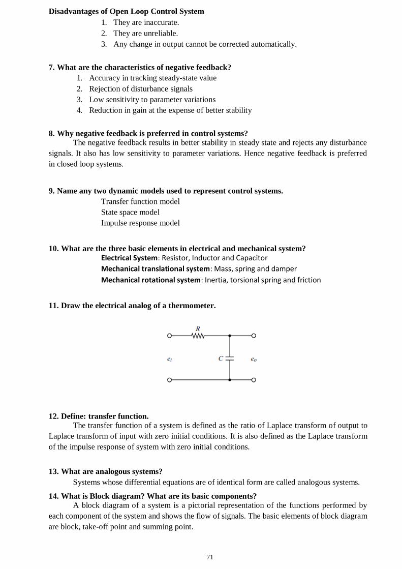
71
Disadvantages of Open Loop Control System
1. They are inaccurate.
2. They are unreliable.
3. Any change in output cannot be corrected automatically.
7. What are the characteristics of negative feedback?
1. Accuracy in tracking steady-state value
2. Rejection of disturbance signals
3. Low sensitivity to parameter variations
4. Reduction in gain at the expense of better stability
8. Why negative feedback is preferred in control systems?
The negative feedback results in better stability in steady state and rejects any disturbance
signals. It also has low sensitivity to parameter variations. Hence negative feedback is preferred
in closed loop systems.
9. Name any two dynamic models used to represent control systems.
Transfer function model
State space model
Impulse response model
10. What are the three basic elements in electrical and mechanical system?
Electrical System: Resistor, Inductor and Capacitor
Mechanical translational system: Mass, spring and damper
Mechanical rotational system: Inertia, torsional spring and friction
11. Draw the electrical analog of a thermometer.
12. Define: transfer function.
The transfer function of a system is defined as the ratio of Laplace transform of output to
Laplace transform of input with zero initial conditions. It is also defined as the Laplace transform
of the impulse response of system with zero initial conditions.
13. What are analogous systems?
Systems whose differential equations are of identical form are called analogous systems.
14. What is Block diagram? What are its basic components?
A block diagram of a system is a pictorial representation of the functions performed by
each component of the system and shows the flow of signals. The basic elements of block diagram
are block, take-off point and summing point.
72
15. What are the advantages of signal flow graph method?
1. Gains of various forward paths and feedback loops are just the product of
corresponding branch gains. No formula is required for their simplification.
2. The Mason’s Gain formula is available which can be used directly to get resultant
transfer function without reduction of signal flow graph. Thus, signal flow graph
clearly and easily highlights the cause and effect relationship in the system.
16. Define Synchros.
A synchro is a device used to convert an angular motion to an electrical signal or vice
versa. It works on the principle of a rotating transformer (Induction motor).
17. What is electrical zero position of a synchro transmitter?
The electrical zero of a synchro transmitter is a position of rotor at which one of the coil to
coil voltages is zero. Any angular motion of the rotor is measured with respect to the electrical
zero position of the rotor.
18. What are the applications of synchros?
The synchros are used in positional control systems (servomechanism) as error detector
and to convert angular displacements to proportional electrical signals. It is also used in control
systems to transmit angular motions from one place to another.
19. What are the differences between a Synchro transmitter and a Synchro control
transformer?
The rotor of a synchro transmitter is of dumb-bell shape, but the rotor of synchro control
transformer is cylindrical. The rotor winding of a synchro transmitter is excited by an ac voltage.
In a synchro control transformer, the induced emf in the rotor is used as an output signal (error
signal)
20. What are the advantages of AC servomotor?
Low cost.
Higher efficiency and less maintenance (because no commutator and brushes).
Can be effectively used in low power applications.
73
UNIT-II TIME RESPONSE ANALYSIS
Part – A
1. List the standard test signals used in time domain analysis.
The commonly used test input signals in control system are impulse, step, ramp,
acceleration and sinusoidal signals.
2. What are transient and steady state responses of a control system?
The transient response is the response of the system when the input changes from one state
to another. The response of the system as t→∞ is called steady state response.
3. Distinguish between steady state and transient response of the system.
Initially output of the system varies as function of time. This portion is called transient
response. While the output settles at a particular value and remains there afterwards, this portion
is called steady state response.
4. How do you find the type of a system?
The number of poles at the origin of a loop transfer function decides the type number of
the system. Hence, by looking at denominator polynomial of the system we can find the type of a
system.
5. Distinguish between type and order of the system.
(i) Type number is specified for loop transfer function but order can be specified for
any transfer function. (open loop or closed loop transfer function)
(ii) The type number is given by number of poles of loop transfer function lying at
origin of s-plane but the order is given by the number of poles of transfer
function.
6. What are type 0 and type 1 system?
Type number of a system is equal to number of poles at origin. Type 0 system do not have
any pole at origin. Type 1 system has one pole at origin.
7. How a control system is classified depending on the value of damping?
Depending on the value of damping, the system can be classified into the following four
cases.
Case 1: Undamped system, τ = 0
Case 2: Underdamped system, 0 < τ
< 1 Case 3: Critically damped
system, τ = 1 Case 4: Over damped
system, τ>1
8. List the time domain specifications.
The time domain specifications are, (i) Delay time (ii) Rise time (iii) Peak time (iv)
Maximum overshoot and (v) Settling time.
9. What is meant by rise time?
It is the time taken for response to raise from 0 to 100%, the very first time. For
underdamped system, the rise time is calculated from 0 to 100%. But for overdamped system it is
the time taken by the response to raise from 10% to 90%. For critically damped system, it is the
time taken for response to raise from 5% to 95%.
10. With reference to time response of a control system, define ‘peak time’.
It is the time taken for the response to reach the peak value, the very first time (or) It is the
time taken for the response to reach peak overshoot, Mp.
74
11. What do you mean by peak over shoot?
It is defined as the ratio of the maximum peak value to final value, where maximum peak
value is measured from final value.
12. Define “Settling time.”
It is defined as the time taken by the response to reach and stay within a specified error
and the error is usually specified as % of final value. The usual tolerable error is 2% or 5% of the
final value.
13. What is a steady state error?
The steady state error is the value of error signal, e(t), when t tends to infinity. The steady
state error is a measure of system accuracy. These errors arise from the nature of inputs, type of
system and from non-linearity of system components.
14. Give the steady state errors to a various standard input for type-2 system.
Unit step: 0 ; Unit ramp: 0; Unit parabolic: 1/Ka
15. What are the advantages of generalized error series?
(i) Generalized error series gives error signal as a function of time.
(ii) Using generalized error constants, the steady state error can be determined for
any type of input but static error constants are used to determine steady state error
when the input is anyone of the standard input.
16. What are the difference between steady state and generalized error coefficients?
Sl. No
Static error coefficients Dynamic error coefficients
1
Static error coefficients fail to indicate the exact manner in which the error function
changes with time
Dynamic error coefficients give error signal as a function of time.
2
They do not give any information on the steady state when inputs are other than the standard test signals.
The steady state error can be determined for any type of input.
17. What is the effect on system performance when a proportional controller is introduced in
a system?
The proportional controller improves the steady state tracking accuracy, disturbance signal
rejection and relative stability of the system. It also increases the loop gain of the system which
results in reducing the sensitivity of the system to parameter variations.
18. Why is the derivative control not used in control systems?
The derivative controller produces a control action based on rate of change of error signal
and it does not produce corrective measures for any constant error. Hence derivative controller is
not used in control systems.
19. State the effect of PI-controller on the system performance.
The PI controller increases the order of the system by one, which results in reducing, the
steady state error. But the system becomes less stable than the original system.
75
20. What is the effect of PD controller on the performance of a system?
The effect of PD-controller is to increase the damping ratio of the system and so the peak
overshoot is reduced.
21. State the effect of PI and PD controller on system performance.
The PI controller increases the order of the system by one, which results in reducing, the
steady state error. But the system becomes less stable than the original system.
The effect of PD-controller is to increase the damping ratio of the system and so the peak
overshoot is reduced.
UNIT-III FREQUENCY RESPONSE
Part – A
1. What is meant by frequency response?
The magnitude and phase function of sinusoidal transfer function of a system are real
function of frequency ω, and so they are called frequency response.
2. What are the advantages of frequency response analysis?
1. The absolute and relative stability of the closed loop system can be estimated from
the knowledge of the open loop frequency response.
2. The practical testing of system can be easily carried with available sinusoidal signal
generators and precise measurement equipment.
3. The transfer function of complicated functions can be determined experimentally by
frequency response testes.
4. The design and parameter adjustment can be carried more easily.
5. The corrective measure for noise disturbance and parameter variation can be easily
carried.
6. It can be extended to certain non-linear systems.
3. What are the frequency domain specifications? (i) Resonant peak (ii) Resonant frequency (iii) Bandwidth
(iv) Cut-off rate (v) Gain margin (vi) Phase margin
4. Define phase and gain crossover frequencies.
The gain cross over frequency is the frequency at which the magnitude of the open loop
transfer function is unity. The phase cross over frequency is the frequency at which the phase of
the open loop transfer function is 1800.
5. Define phase and gain margin.
The gain margin, Kg is defined as the value by which gain of the system has to be
increased to drive system to be verge of instability.
The phase margin, γ is that amount of additional phase lag at the gain cross-over
frequency, ωgc required to bring the system to the verge of instability.
6. Define the terms: ‘resonant peak’, and ‘resonant frequency’.
76
The maximum value of the magnitude of closed loop transfer function is called resonant
peak. The frequency at which the resonant peak occurs is called resonant frequency.
7. What is cut-off frequency?
The frequency at which the magnitude of the system is -3db is called as cut-off frequency.
8. What does a gain margin close to unity or phase margin close to zero indicate?
A gain margin close to unity or phase margin close to zero indicate a highly oscillatory
system.
9. Write the correlation of time domain specifications and frequency domain specifications.
Correlation exists between time and frequency response of first or second order systems.
The frequency domain specifications can be expressed in terms of the time domain parameters τ
and ωn. For a peak overshoot in time domain there is a corresponding resonant peak in frequency
domain.
10. What is the basis for the selection of a particular compensator for a system?
When mainly transient response is to be improved, a lead compensator is chosen. When
steady-state response is to be improved, while nearly preserving the transient response, a lag
compensator is chosen. When both the transient and steady state responses are to be improved, a
lag-lead compensator is chosen.
11. What are the advantages of Bode plot?
1. The magnitudes are expressed in db, and so, a simple procedure is available to add
magnitude of each term one by one.
2. The approximate bode plot can be quickly sketched, and the corrections can be made at
corner frequencies to get the exact plot.
3. The frequency domain specifications can be easily determined.
4. The bode plot can be used to analyse both open loop and closed loop system.
12. What is Corner frequency?
The magnitude plot can be approximated by asymptotic straight lines. The frequencies
corresponding to the meeting point of asymptotes are called corner frequency. The slope of the
magnitude plot changes at every corner frequency.
13. What is Lag-Lead Compensation?
The lag-lead compensation is a design procedure in which a lag-lead compensator is
introduced in the system so as to meet the desired performance.
14. What are the characteristics of phase lead network?
Increases system bandwidth which usually correlates to reduced rise and settling
times
and a susceptibility to high frequency noise.
Increases the phase of the forward-path transfer function in the vicinity of the
zero-gain crossover frequency. This increases the phase margin of the closed-
loop system and hence the relative stability.
15. What are M & N circles?
The magnitude, M of closed loop transfer function with unity feedback will be in the form
of circle in complex plane for each constant value of M. The family of these circles are called M-
circles.
77
Let N = tan α, where α is the phase of closed loop transfer function with unity feedback.
For each constant value of N, a circle can be drawn in the complex plane. The family of these
circles are called N-circles.
16. What is the use of Nichol’s chart?
1. The complete closed loop frequency response can be obtained.
2. The value of Mr can be obtained
3. The 3 dB bandwidth of closed loop system can be obtained.
4. The frequency wr corresponding to Mr can be obtained.
17. How will you get closed loop frequency response from open loop response?
The G(jω) locus or polar plot of open loop system is sketched on the standard M and N
circles chart. The meeting point of M circle with G(jω) locus gives the magnitude of closed loop
system. The meeting point of G(jω) locus with N-circle gives the value of phase of closed loop
system.
18. What is Nichols chart? List the advantages of Nichol’s chart?
The Nichols chart consists of M and N contours superimposed on ordinary graph. Along each M-
contour the magnitude of closed loop system, M will be a constant. Along each N-contour, the
phase α of closed loop system will be constant.
19. What is Nichols plot?
The Nichols plot is a frequency response plot of the open loop transfer function of a system. It is a
graph between magnitude of G(jω) in db and the phase of G(jω) in degree, plotted on an ordinary
graph sheet.
20. What are the effects and limitations of phase-lag control?
For a given forward path gain K, the magnitude of the forward path transfer
function is attenuated near and above the gain crossover frequency, thus allowing
improvement of the relative stability of the system. The additional attenuation of
high frequencies improve the signal to noise ratio of the system.
The gain crossover frequency is decreased and the bandwidth of the system is
reduced, the rise time and settling times are longer.
The system is more sensitive to parameter variations.
78
UNIT-IV STABILITY AND COMPENSATOR DESIGN Part – A
1. What is characteristic equation?
The denominator polynomial of C(s)/R(s) is the characteristic equation of the system.
2. What is BIBO stability criterion?
A linear relaxed system is said to have BIBO stability if every bounded (finite) input results in a
bounded (finite) output.
3. Define stability of a system.
A system is stable if for a bounded disturbing input signal, the output vanishes ultimately as
t approaches infinity.
4. What are two notions of system stability to be satisfied for a linear time-invariant system
to be stable?
(i) When the system is excited by a bounded input, the output is bounded.
(ii) In the absence of the input, the output tends to zero irrespective of the
initial conditions.
5. Define relative stability.
System is said to be relatively more stable if settling time for that system is less than that of the
other system. Relative stability of the system improves, as the closed loop poles move away
from the imaginary axis in left half of s-plane.
6. How are the roots of the characteristic equation of a system related to stability?
If the roots of the characteristic equation have positive real part, then the impulse response of the
system is not bounded. Hence the system will be unstable.
If the roots of the characteristic equation have negative real part, then the impulse response is
bounded. Hence the system will be stable.
7. State the necessary and sufficient condition for stability.
The necessary condition for stability is that all the coefficients of the characteristic polynomial
be positive.
The necessary and sufficient condition for stability is that all of the elements in the first column
of the Routh array should be positive.
8. State any two limitations of Routh-stability criterion.
1. It is valid only for real coefficients of the characteristic equation.
2. It does not provide exact locations of the closed loop poles in left or right half of s-
plane.
3. It does not suggest methods of stabilising an unstable system.
4. Applicable only to linear systems.
9. Define Nyquist stability criterion.
If G(s)H(s) contour in the G(s)H(s) plane corresponding to Nyquist contour in s-plane
encircles the point -1+j0 in the anticlockwise direction as many times as the number of right
half s-plane poles of G(s)H(s). Then the closed loop system is stable.
79
10. State the advantages of Nyquist stability criterion over that of Routh’s criterion.
1. It gives information about absolute stability of the system
2. Useful for determining the stability of the closed loop system from open loop
transfer function without knowing the roots of the characteristic equation.
3. It also indicates relative stability giving the values of GM and PM.
4. It indicates reality, the manner in which system should be compensated to yield
desired response.
5. Information regarding frequency response can be obtained.
6. Very useful for analysing conditionally stable systems.
11. Define compensator and list the types of compensators?
A device inserted into the system for the purpose of satisfying the specifications is called
compensator. The different types of compensators are lag, lead and lag-lead compensator.
12. Why compensation is needed in feedback control system?
In feedback control systems compensation is required in the following situations.
1. When the system is absolutely unstable, then compensation is required to stabilize
the system and also to meet the desired performance.
2. When the system is stable, compensation is provided to obtain the desired
performance.
13. What are the primary advantages of the frequency domain design of control system?
The advantages of frequency domain design are the following
1. The effect of disturbances, sensor noise and plant uncertainties are easy to visualize
and asses in frequency domain.
2. The experimental verification can be used for design purpose.
14. Why the frequency domain compensation is normally carried out using Bode plots?
The Bode plots are easier to draw and modify.
Bode plot retains the original shape ever after compensation. So, it can be easily
visualized. Graphical addition of Bode plots of compensator and
uncompensated system gives Bode plot of compensated system.
The gain adjustment can be conveniently carried out using the Bode plots.
Gain adjustment just shifts the Bode plot up and down only.
The error constants are always clearly in evidence when the Bode plots are used.
15. What type of compensator suitable for high frequency noisy environment?
Lag compensator. A lag compensator acts as low pass filter and does not allow high
frequency noise signal to enter into the system. Hence lag compensator is suitable for high
frequency noisy environment.
16. List out the advantages and disadvantages of phase lag network.
Advantages
a. Phase lag network allows low frequencies and high frequencies are attenuated.
b. Due to the presence of phase lag compensation the steady state accuracy increases.
Disadvantages
a. Due to the presence of phase lag compensation the speed of the system decreases.
17. What is lead compensator? When it is preferred?
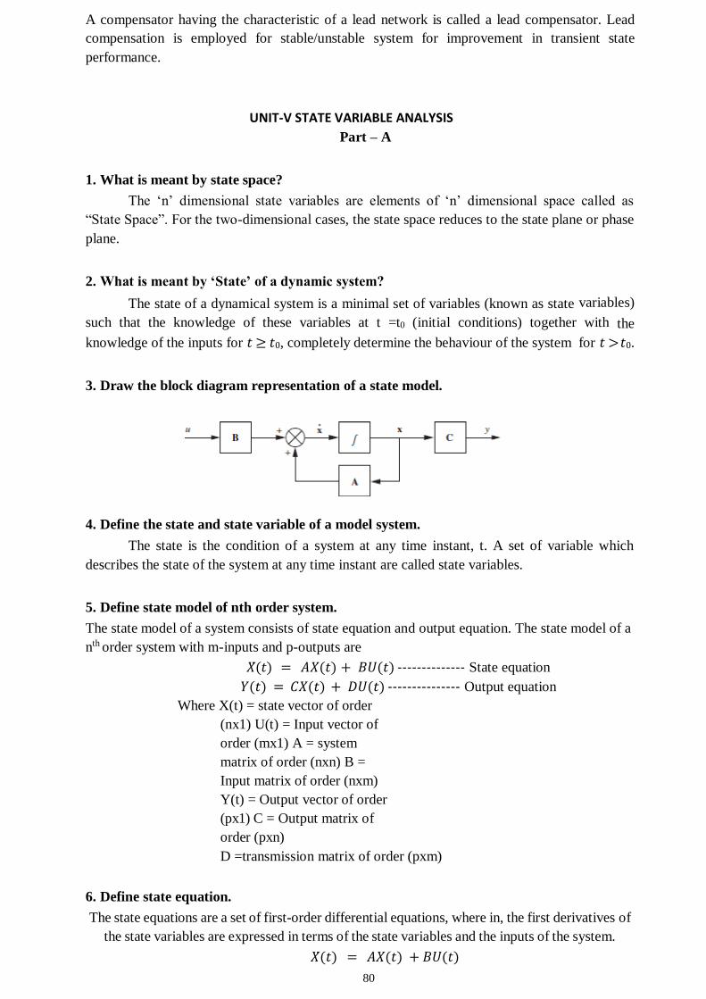
80
A compensator having the characteristic of a lead network is called a lead compensator. Lead
compensation is employed for stable/unstable system for improvement in transient state
performance.
UNIT-V STATE VARIABLE ANALYSIS
Part – A
1. What is meant by state space?
The ‘n’ dimensional state variables are elements of ‘n’ dimensional space called as
“State Space”. For the two-dimensional cases, the state space reduces to the state plane or phase
plane.
2. What is meant by ‘State’ of a dynamic system?
The state of a dynamical system is a minimal set of variables (known as state variables)
such that the knowledge of these variables at t =t0 (initial conditions) together with the
knowledge of the inputs for 𝑡 ≥ 𝑡0, completely determine the behaviour of the system for 𝑡 > 𝑡0.
3. Draw the block diagram representation of a state model.
4. Define the state and state variable of a model system.
The state is the condition of a system at any time instant, t. A set of variable which
describes the state of the system at any time instant are called state variables.
5. Define state model of nth order system.
The state model of a system consists of state equation and output equation. The state model of a
nth order system with m-inputs and p-outputs are
𝑋̇ (𝑡) = 𝐴𝑋̇(𝑡) + 𝐵𝑈(𝑡) -------------- State equation
𝑌(𝑡) = 𝐶𝑋̇(𝑡) + 𝐷𝑈(𝑡) --------------- Output equation
Where X(t) = state vector of order
(nx1) U(t) = Input vector of
order (mx1) A = system
matrix of order (nxn) B =
Input matrix of order (nxm)
Y(t) = Output vector of order
(px1) C = Output matrix of
order (pxn)
D =transmission matrix of order (pxm)
6. Define state equation.
The state equations are a set of first-order differential equations, where in, the first derivatives of
the state variables are expressed in terms of the state variables and the inputs of the system.
𝑋̇ (𝑡) = 𝐴𝑋̇(𝑡) + 𝐵𝑈(𝑡)
81
7. Name the methods of state space representation for phase variables.
1. Companion form
2. Direct decomposition of transfer function
3. Controllable canonical form
4. Observable canonical form
8. Mention the need for state variables?
In the conventional approach, the significant initial conditions lose their importance. It is not
suitable for analysing higher order systems and multiple input and multiple output systems. It is
suitable only linear time invariant systems. All these limitations are eliminated in state variable
method. Thus, to obtain the precise optimum solution considering the initial conditions for any
type of input the state variables are necessary.
9. What are the advantages of state space representation?
a. The state space analysis is applicable to any type of systems. They can be used
for modelling and analysis of linear and nonlinear systems, time invariant &
time variant systems and multiple input & multiple output systems.
b. The state space analysis can be performed with initial conditions.
c. The variables used to represent the system can be any variables in the system.
d. Using this analysis, the internal states of the system at any time instant can be
predicted.
10. When a system is said to be completely observable?
A system is said to be observable at time t0, if with the system in state x(t0), it is possible to
determine this state from the observation of the output over a finite time interval.
11. When do you say that a system is completely state controllable?
A system is said to be completely state controllable at time t0, if it is possible by means
of an un constrained control vector u(t) to transfer the system from an initial state x(t0)
to any other desired state x(t) in a finite interval of time.
12. Define observability of a system.
A system is said to be completely state observable if every state X(t) can be completely
identified by measurements of the output Y(t) over a finite time interval.
13. Define controllability of a system.
A system is said to be completely state controllable if it is possible to transfer the system state
from any initial state X(t0) at any other desired state X(t), in specified finite time by a control
vector U(t).
14. What are the drawbacks of transfer function approach?
Transfer function is defined under zero initial conditions.
Transfer function is applicable to linear time invariant systems.
Transfer function analysis is restricted to SISO systems.
It does not provide information regarding the internal state of the system.
82
15. What are phase variables?
The phase variables are defined as those particular state variables which are obtained from one
of the system variable and its derivatives. Usually the variable used is the system output and the
remaining state variables and then derivatives.
16. What is canonical form of state model?
If the system matrix, A is in the form of diagonal matrix then the state model is called canonical
form.
17. What is pole placement by state feedback?
The pole placement by state feedback is a control system design technique in which the state
variables are used for feedback to achieve the desired closed loop poles
18. What are the advantages of state space modelling using physical variable?
1. The state variable can be utilized for the purpose of feedback.
2. The solution of state equation gives time variation of variables which have direct
relevance to the Physical system.
19. State the limitations of state variable feedback.
State feedback is not usually practical for two reasons: (i) State feedback tends to PD type or
PID compensators which have infinite bandwidth, whereas real components and compensators
always have finite bandwidth. (ii) It is simply not possible or practical to sense all the states and
feed them back. In reality, only certain states or combinations of states are measurable as
outputs. Consequently, any practical compensator must rely on system outputs, inputs, and a few
state variables for compensation.
20. What is zero input response of a system? How to obtain it?
The behaviour of X(t) under the initial conditions without any input U(t) is called the zero-
input response of the system. It is obtained as 𝑒𝐴𝑡𝑋̇(0) where 𝑒𝐴𝑡 is state transition matrix and
X(0) is the initial state vector.
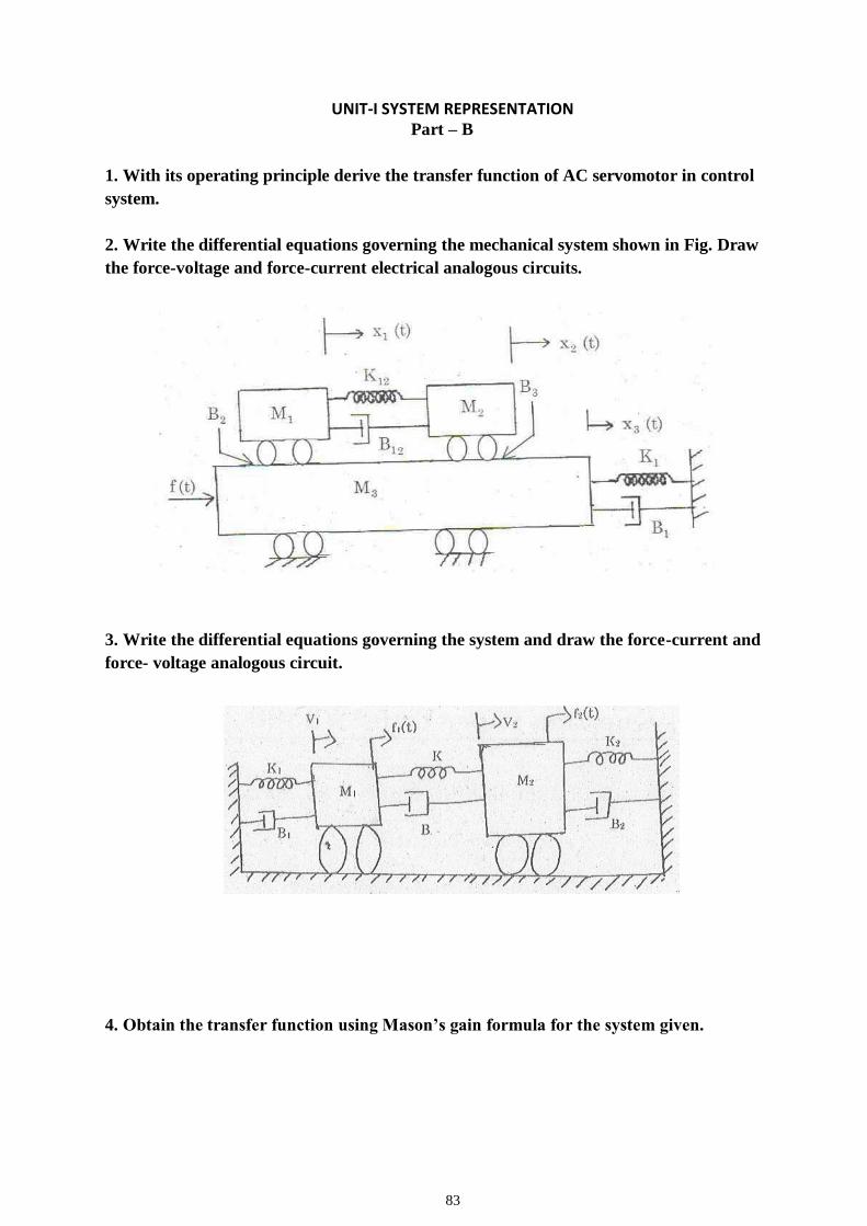
83
UNIT-I SYSTEM REPRESENTATION Part – B
1. With its operating principle derive the transfer function of AC servomotor in control
system.
2. Write the differential equations governing the mechanical system shown in Fig. Draw
the force-voltage and force-current electrical analogous circuits.
3. Write the differential equations governing the system and draw the force-current and
force- voltage analogous circuit.
4. Obtain the transfer function using Mason’s gain formula for the system given.
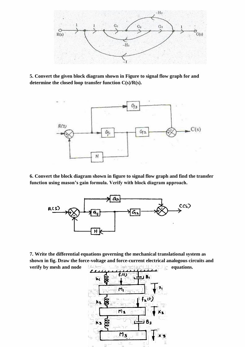
84
5. Convert the given block diagram shown in Figure to signal flow graph for and
determine the closed loop transfer function C(s)/R(s).
6. Convert the block diagram shown in figure to signal flow graph and find the transfer
function using mason’s gain formula. Verify with block diagram approach.
7. Write the differential equations governing the mechanical translational system as
shown in fig. Draw the force-voltage and force-current electrical analogous circuits and
verify by mesh and node equations.
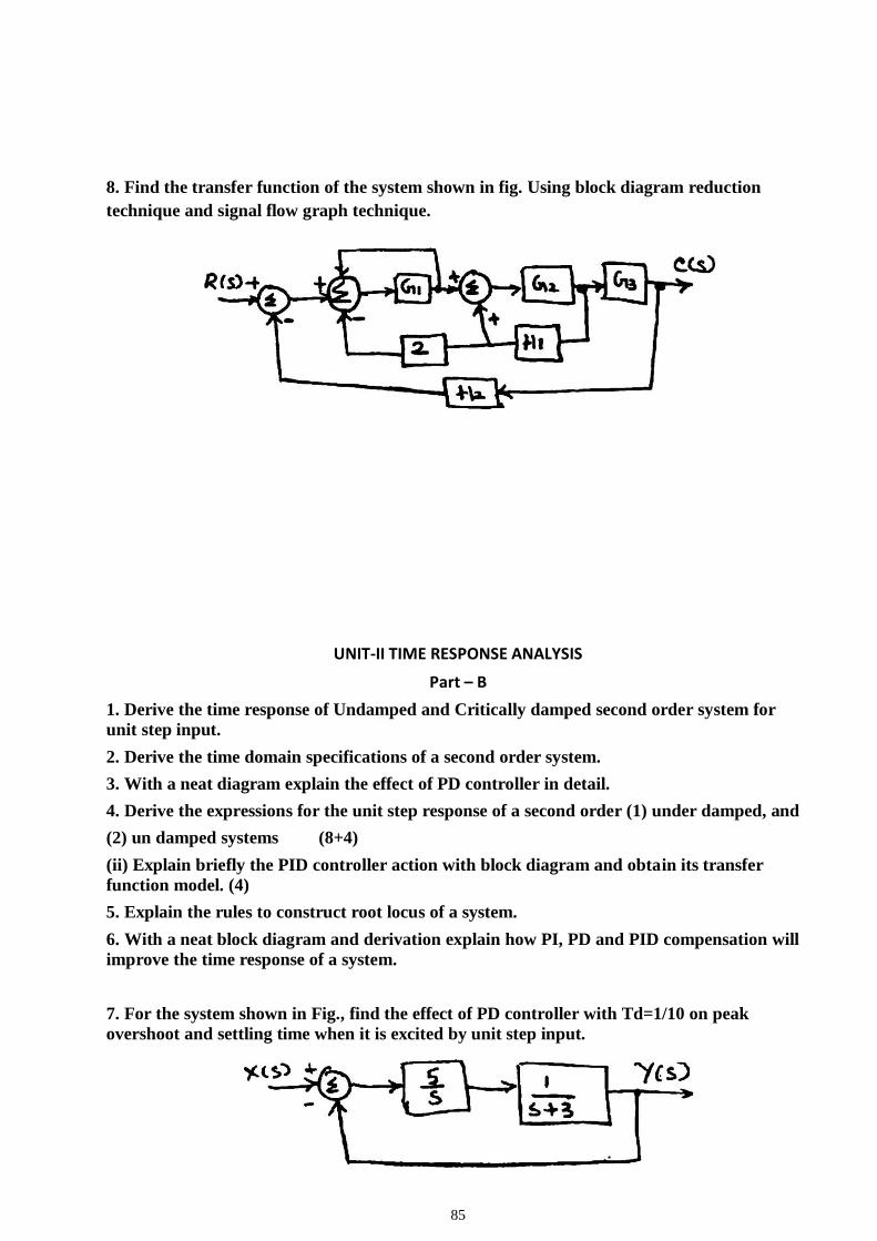
85
8. Find the transfer function of the system shown in fig. Using block diagram reduction
technique and signal flow graph technique.
UNIT-II TIME RESPONSE ANALYSIS
Part – B
1. Derive the time response of Undamped and Critically damped second order system for
unit step input.
2. Derive the time domain specifications of a second order system.
3. With a neat diagram explain the effect of PD controller in detail.
4. Derive the expressions for the unit step response of a second order (1) under damped, and
(2) un damped systems (8+4)
(ii) Explain briefly the PID controller action with block diagram and obtain its transfer
function model. (4)
5. Explain the rules to construct root locus of a system.
6. With a neat block diagram and derivation explain how PI, PD and PID compensation will
improve the time response of a system.
7. For the system shown in Fig., find the effect of PD controller with Td=1/10 on peak
overshoot and settling time when it is excited by unit step input.
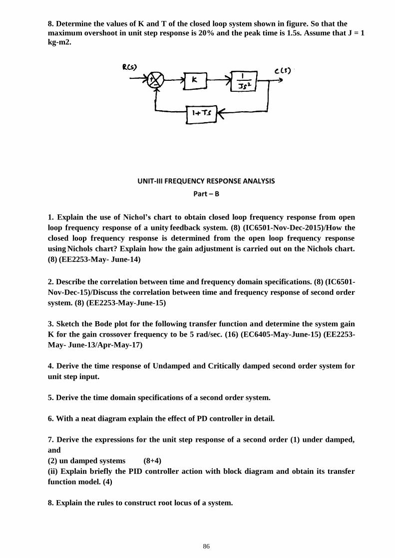
86
8. Determine the values of K and T of the closed loop system shown in figure. So that the
maximum overshoot in unit step response is 20% and the peak time is 1.5s. Assume that J = 1
kg-m2.
UNIT-III FREQUENCY RESPONSE ANALYSIS
Part – B
1. Explain the use of Nichol’s chart to obtain closed loop frequency response from open
loop frequency response of a unity feedback system. (8) (IC6501-Nov-Dec-2015)/How the
closed loop frequency response is determined from the open loop frequency response
using Nichols chart? Explain how the gain adjustment is carried out on the Nichols chart.
(8) (EE2253-May- June-14)
2. Describe the correlation between time and frequency domain specifications. (8) (IC6501-
Nov-Dec-15)/Discuss the correlation between time and frequency response of second order
system. (8) (EE2253-May-June-15)
3. Sketch the Bode plot for the following transfer function and determine the system gain
K for the gain crossover frequency to be 5 rad/sec. (16) (EC6405-May-June-15) (EE2253-
May- June-13/Apr-May-17)
4. Derive the time response of Undamped and Critically damped second order system for
unit step input.
5. Derive the time domain specifications of a second order system.
6. With a neat diagram explain the effect of PD controller in detail.
7. Derive the expressions for the unit step response of a second order (1) under damped,
and
(2) un damped systems (8+4)
(ii) Explain briefly the PID controller action with block diagram and obtain its transfer
function model. (4)
8. Explain the rules to construct root locus of a system.
87
UNIT-IV STABILITY AND COMPENSATOR DESIGN
Part – B
1. Explain in detail the realization of Lag, Lead and Lag-Lead electrical networks.
2. State and explain Nyquist stability criterion
3. Use R-H criterion to determine the location of the roots and stability for the
system represented by characteristic equation 𝑠5 + 4𝑠4 + 8𝑠3 + 8𝑠2 + 7𝑠 + 4 = 0.
4. Explain the procedure for the design of a lead compensator using Bode plot.
Write down the procedure for designing Lead compensator using Bode plot.
Explain the design procedure of a lead compensator with a suitable example.
5. Using Routh Hurwitz criterion, determine the stability of a system
representing the characteristic equation 𝑠6 + 2𝑠5 + 8𝑠4 + 12𝑠3 + 20𝑠2 + 16𝑠 +
16 = 0 and comment on location of the roots of the characteristics equation.
6. Design a lead compensator for the system G(s) = 1/s(s+2) with damping
coefficient equal to 0.45, velocity error constant > 20 and small setting time.
7. Draw the Nyquist plot and find the stability of the following open loop transfer
function of unity feedback control system G(s)H(s) = K(s+1)/s2(s+10). If the
system is conditionally stable, find the range of K for which the system is
stable.
8. Write the procedure for the design of lag compensator and lag-lead compensator
using bode plot. (8+8)
9. Explain the electric network realization of a lead compensator and also its
frequency response characteristics.
10.Write the design procedure for lag-lead compensator using Bode-plot. Derive
the transfer function of a lag-lead compensator based on electrical network.
UNIT-V STATE VARIABLE ANALYSIS Part – B
1. Obtain the state model of the mechanical system shown in fig., in which f(t) is the input
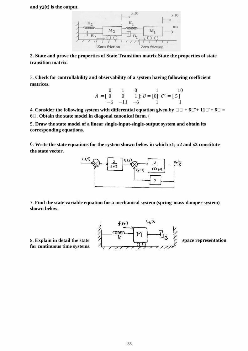
88
and y2(t) is the output.
2. State and prove the properties of State Transition matrix State the properties of state
transition matrix.
3. Check for controllability and observability of a system having following coefficient
matrices.
0 1 0 1 10 𝐴 = [ 0 0 1 ]; 𝐵 = [0]; 𝐶𝑇 = [ 5 ]
−6 −11 −6 1 1
4. Consider the following system with differential equation given by ⃛⃛ + 6⃛ + 11⃛ + 6⃛ =
6⃛. Obtain the state model in diagonal canonical form. (
5. Draw the state model of a linear single-input-single-output system and obtain its
corresponding equations.
6. Write the state equations for the system shown below in which x1; x2 and x3 constitute
the state vector.
7. Find the state variable equation for a mechanical system (spring-mass-damper system)
shown below.
8. Explain in detail the state space representation
for continuous time systems.

89
EE6502- MICROPROCESSORS AND MICROCONTROLLERS
QUESTION BANK
1. What is Microprocessor ?
It is a program controlled semiconductor device (IC}, which fetches, decode and executes
instructions.
2. What are the basic units of a microprocessor ?
The basic units or blocks of a microprocessor are ALU, an array of registers and control unit
3.what is Software and Hardware?
The Software is a set of instructions or commands needed for performing a specific task by a
programmable device or a computing machine.
The Hardware refers to the components or devices used to form computing machine in
which the software can be run and tested. Without software the Hardware is an idle
machine.
4. What is assembly language?
The language in which the mnemonics (short -hand form of instructions) are used to write a
program is called assembly language. The manufacturers of microprocessor give the
mnemonics
5. What are machine language and assembly language programs?
The software developed using 1's and 0's are called machine language, programs. The
software developed using mnemonics are called assembly language programs.
6. What is the drawback in machine language and assembly language, programs?
The machine language and assembly language programs are machine dependent. The
programs developed using these languages for a particular machine cannot be directly run on
another machine .
7. Define bit, byte and word.
A digit of the binary number or code is called bit. Also, the bit is the fundamental storage
unit of computer memory.
The 8-bit (8-digit) binary number or code is called byte and 16-bit binary number or code is
called word. (Some microprocessor manufactures refer the basic data size operated by the
processor as word).
8. What is a bus?
Bus is a group of conducting lines that carries data, address and control signals.
9. Why data bus is bi-directional?
The microprocessor has to fetch (read) the data from memory or input device for processing
and after processing, it has to store (write) the data to memory or output device. Hence the
90
data bus is bi-directional.
10. Why address bus is unidirectional?
The address is an identification number used by the microprocessor to identify or access a
memory location or I / O device. It is an output signal from the processor. Hence the address
bus is unidirectional.
11. What is the function of microprocessor in a system?
The microprocessor is the master in the system, which controls all the activity of the system.
It issues address and control signals and fetches the instruction and data from memory. Then
it executes the instruction to take appropriate action.
12. What are the modes in which 8086 can operate?
The 8086 can operate in two modes and they are minimum (or uniprocessor) mode and
maximum ( or multiprocessor) mode.
13. What is the data and address size in 8086?
The 8086 can operate on either 8-bit or 16-bit data. The 8086 uses 20 bit address to access
memory and 16-bit address to access 1/0 devices.
14. Explain the function of M/IO in 8086.
The signal M/IO is used to differentiate memory address and 1/0 address When the processor
is accessing memory locations MI 10 is asserted high and when it is accessing 1/0 mapped
devices it is asserted low.
15. Write the flags of 8086.
The 8086 has nine flags and they are
Carry Flag (CF) 6. Overflow Flag (OF)
Parity Flag (PF) 7. Trace Flag (TF)
Auxiliary carry Flag (AF) 8. Interrupt Flag (IF)
Zero Flag (ZF) 9. Direction Flag (DF)
Sign Flag (SF)
16. What are the interrupts of 8086?
The interrupts of 8085 are INTR and NMI. The INTR is general maskable interrupt and NMI
is non-maskable interrupt.
17. How clock signal is generated in 8086? What is the maximum internal clock frequency of
8086?
The 8086 does not have on-chip clock generation circuit. Hence the clock generator chip,
8284 is connected to the CLK pin of8086. The clock signal supplied by 8284 is divided by
three for internal use. The maximum internal clock frequency of8086 is 5MHz.
91
18. Write the special functions carried by the general purpose registers of 8086.
The special functions carried by the registers of 8086 are the following.
Register Special function
1. AX 16-bit Accumulator
2. AL 8-bit Accumulator
3. BX Base Register
4. CX Count Register
5. DX .Data Register 11. What is pipelined architecture?
In pipelined architecture the processor will have number of functional units and the execution
time of functional units are overlapped. Each functional unit works independently most of the
time.
12. What are the functional units available in 8086 architecture?
The bus interface unit and execution unit are the two functional units
available in 8086 architecture21. List the segment registers of 8086.
The segment registers of 8086 are Code segment, Data segment, Stack segment and Extra
segment registers.
22. Define machine cycle.
Machine cycle is defined as the time required to complete one operation of accessing
memory, I/O, or acknowledging an external request. This cycle may consist of three to six T-
states
23. Define T-State.
T-State is defined as one subdivision of the operation performed in one clock period.
These subdivisions are internal states synchronized with the system clock, and each T-
State is precisely equal to one clock period.
24. List the components of microprocessor (single board microcomputer) based system
The microprocessor based system consist of microprocessor as CPU, semiconductor
memories like EPROM and RAM, input device, output device and interfacing devices.
25. Why interfacing is needed for 1/0 devices?
Generally I/O devices are slow devices. Therefore the speed of I/O devices does not match
with the speed of microprocessor. And so an interface is provided between system bus and
I/O devices
92
26. What is the difference between CPU bus and system bus?
The CPU bus has multiplexed lines but the system bus has separate lines for each signal.
(The multiplexed CPU lines are demultiplexed by the CPU interface circuit to form system
bus).
27..What does memory-mapping mean?
The memory mapping is the process of interfacing memories to microprocessor and
allocating addresses to each memory locations.
28..What is interrupt 1/0?
If the 1/0 device initiate the data transfer through interrupt then the 1/0 is called interrupt
driven 1/0.
29. Why EPROM is mapped at the beginning of memory space in 8085
system?
In 8085 microprocessor, after a reset, the program counter will have OOOOH address. If the
monitor program is stored from this address then after a reset, it will be executed
automatically. The monitor
program is a permanent program and stored in EPROM memory. If EPROM memory is
mapped at the beginning of memory space, i.e., at OOOOH, then the monitor program will
be executed automatically after a reset.
30. What is the need for system clock and how it is generated in 8085?
The system clock is necessary for synchronizing various internal operations or devices in the
microprocessor and to synchronize the microprocessor with other peripherals in the system.
31.What is DMA?
The direct data transfer between I/O device and memory is called DMA.
32. What is the need for Port?
The I/O devices are generally slow devices and their timing characteristics do not match
with processor timings. Hence the I/O devices are connected to system bus through the
ports.
33.What is a port?
The port is a buffered I/O, which is used to hold the data transmitted from the
microprocessor to I/O device or vice-versa. 34.Give some examples of port devices used in 8085 microprocessor based system?
The various INTEL I/O port devices used in 8085 microprocessor based system are 8212,
8155, 8156, 8255, 8355 and 8755.

93
35. Write a short note on INTEL 8255?
The INTEL 8255 is a I/O port device consisting of 3 numbers of 8 -bit parallel I/O ports.
The ports can be programmed to function either as a input port or as a output port in
different operating modes. It requires 4 internal addresses and has one logic LOW chip
select pin.
36.What is the drawback in memory mapped I/0?
When I/O devices are memory mapped, some of the addresses are allotted to I/O devices
and so the full address space cannot be used for addressing memory (i.e., physical memory
address space will be reduced). Hence memory mapping is useful only for small systems,
where the memory requirement is less.
37. How DMA is initiated?
When the I/O device needs a DMA transfer, it will send a DMA request signal to DMA
controller. The DMA controller in turn sends a HOLD request to the processor. When the
processor receives a HOLD request, it will drive its tri-stated pins to high impedance state at
the end of current instruction execution and send an acknowledge signal to DMA controller.
Now the DMA controller will perform DMA transfer.
38. What is processor cycle (Machine cycle)?
The processor cycle or machine cycle is the basic operation performed by the processor. To
execute an instruction, the processor will run one or more machine cycles in a particular
order.
39. What is Instruction cycle?
The sequence of operations that a processor has to carry out while executing the instruction
is called Instruction cycle. Each instruction cycle of a processor indium consists of a number
of machine cycles.
40. What is fetch and execute cycle?
In general, the instruction cycle of an instruction can be divided into fetch and execute
cycles. The fetch cycle is executed to fetch the opcode from memory. The execute cycle is
executed to decode the instruction and to perform the work instructed by the instruction.
41.What is Block and Demand transfer mode DMA?
In Block transfer mode, the DMA controller will transfer a block of data and relieve the bus
for processor. After sometime another block of data is transferred by DMA and so on.
In Demand transfer mode the DMA controller will complete the entire
.data transfer at a stretch and then relieve the bus to processor.
94
42. What is the need for timing diagram? The timing diagram provides information regarding the status of various signals, when a machine
cycle is executed. The knowledge of timing diagram is essential for system designer to select
matched peripheral devices like memories, latches, ports, etc., to form a microprocessor system.
43. How many machine cycles constitute one instruction cycle in 8085?
Each instruction of the 8085 processor consists of one to five machine cycles.
44. Define opcode and operand.
Opcode (Operation code) is the part of an instruction / directive that identifies a specific
operation.
Operand is a part of an instruction / directive that represents a value on which the
instruction acts.
45. What is opcode fetch cycle?
The opcode fetch cycle is a machine cycle executed to fetch the opcode of an instruction
stored in memory. Every instruction starts with opcode fetch machine cycle. 46. What operation is performed during first T -state of every machine cycle in 8085 ?
In 8085, during the first T -state of every machine cycle the low byte address is latched into
an external latch using ALE signal.
47. Why status signals are provided in microprocessor?
The status signals can be used by the system designer to track the internal operations of the
processor. Also, it can be used for memory expansion (by providing separate memory banks
for program & data and selecting the bank using status signals).
48. How the 8085 processor differentiates a memory access (read/write) and 1/0 access
(read/write)?
The memory access and 1/0 access is differentiated using 10 I M signal. The 8085 processor
asserts 10 I M low for memory read/write operation and 10 I M is asserted high for 1/0
read/write operation.
49. When the 8085 processor checks for an interrupt?
In the second T -state of the last machine cycle of every instruction, the 8085 processor
checks whether an interrupt request is made or not.
50. What is interrupt acknowledge cycle?
The interrupt acknowledge cycle is a machine cycle executed by 8085 processor to get the
95
address of the interrupt service routine in-order to service the interrupt device.
51. How the interrupts are affected by system reset?
Whenever the processor or system is resetted , all the interrupts except TRAP are disabled. fu
order to enable the interrupts, El instruction has to be executed after a reset.
52. What is Software interrupts?
The Software interrupts are program instructions. These instructions are inserted at desired
locations in a program. While running a program, if software interrupt instruction is
encountered then the processor executes an interrupt service routine.
53. What is Hardware interrupt?
If an interrupt is initiated in a processor by an appropriate signal at the interrupt pin, then the
interrupt is called Hardware interrupt.
54. What is the difference between Hardware and Software interrupt?
The Software interrupt is initiated by the main program, but the Hardware interrupt is
initiated by an external device.
In 8085, the Software interrupt cannot be disabled or masked but the Hardware interrupt
except TRAP can be disabled or masked.
55. What is Vectored and Non- Vectored interrupt?
When an interrupt is accepted, if the processor control branches to a specific address defined
by the manufacturer then the interrupt is called vectored interrupt.
In Non-vectored interrupt there is no specific address for storing the interrupt service
routine. Hence the interrupted device should give the address of the interrupt service
routine.
56. List the Software and Hardware interrupts of 8085?
Software interrupts: RST 0, RSTl, RST 2,
RST 3, RST 4, RST 5,
RST 6 and RST 7.
Hardware interrupts: TRAP, RST 7.5, RST 6.5,
RST 5.5 and INTR. 57. What is TRAP?
The TRAP is non-maskable interrupt of8085. It is not disabled by processor reset or after
reorganization of interrupt.
58. Whether HOLD has higher priority than TRAP or not?
96
The interrupts including mAP are recognized only if the HOLD is not valid, hence TRAP has
lower priority than HOLD.59. What is masking and why it is required?
Masking is preventing the interrupt from disturbing the current program execution. When
the processor is performing an important job (process) and if the process should not be
interrupted then all the interrupts should be masked or disabled.
In processor with multiple 'interrupts, the lower priority interrupt can be masked so as to
prevent it from interrupting, the execution of interrupt service routine of higher priority
interrupt.
60. When the 8085 processor accept hardware interrupt?
The processor keeps on checking the interrupt pins at the second T -state of last Machine
cycle of every instruction. If the processor finds a valid interrupt signal and if the interrupt is
unmasked and enabled then the processor accepts the interrupt. The acceptance of the
interrupt is acknowledged by sending an OOA signal to the interrupted device.
61. When the 8085 processor will disable the interrupt system?
The interrupts of 8085 except TRAP are disabled after anyone of the following operations
1. Executing El instruction.
2. System or processor reset.
3. After reorganization (acceptance) of an interrupt. 62. What is the function performed by Dl instruction?
The function of Dl instruction is to enable the disabled interrupt system
63. What is the function performed by El instruction?
The El instruction can be used to enable the interrupts after disabling. 64. How the vector address is generated for the INTR interrupt of 8085?
For the interrupt INTR, the interrupting device has to place either RST opcode or CALL
opcode followed by l6-bit address. I~RST opcode is placed then the corresponding vector
address is generated by the processor. In case of CALL opcode the given l6-bit address will
be the vector address.
65. How clock signals are generated in 8085 and what is the frequency of the internal clock?
97
The 8085 has the clock generation circuit on the chip but an external quartz crystal or L C
circuit or RC circuit should be connected at the pins XI and X2. The maximum internal
clock frequency of 8085A is 3.03 MHz.
66. What happens to the 8085 processor when it is resetted?
When the 8085 processor is resetted it execute the first instruction at the OOOOH location.
The 8085 resets (clears) instruction register, interrupt mask bits and other registers.
67. What are the operations performed by ALU of 8085?
The operations performed by ALU of 8085 are Addition, Subtraction, Logical AND, OR,
Exclusive OR, Compare Complement, Increment, Decrement and Left I Right shift
68. What is a flag?
Flag is a flip flop used to store the information about the status of the processor and the
status of the instruction executed most recently.
69. List the flags of 8085
There are five flags in 8085. They are sign flag, zero flag, Auxiliary carry flag, parity flag
and carry flag.
70. What is the Hardware interrupts of 8085?
The hardware interrupts in 8085 are TRAP, RST 7.5, RST 6.5 and RST 71.Which interrupt has highest priority in 8085? What is the priority of other interrupts?
The TRAP has the highest priority, followed by RST 7.5, RST 6.5, RST 5.5 and INTR.
72 What is an ALE?
The ALE (Address Latch Enable) is a signal used to demultiplex the address and data lines,
using an external latch. It is used to enable the external latch.
73. Explain the function of IO/M in 8085.
The IO/M is used to differentiate memory access and I/O access. For IN and OUT instruction
it is high. For memory reference instructions it is low.
74. Where is the READY signal used?
READY is an input signal to the processor, used by the memory or I/O devices to get extra
time for data transfer or to introduce wait states in the bus cycles.
75. What is HOLD and HLDA and how it is used?
Hold and hold acknowledge signals are used for the Direct Memory Access (DMA) type of
data transfer. The DMA controller place a high on HOLD pin in order to take control of the
98
system bus. The HOLD request is acknowledged by the 8085 by driving all its tristated pins
to high impedance state and asserting HLDA signal high.
76.What is Polling?
Polling is a scheme or an algorithm to identify the devices interrupting the processor. Polling
is employed when multiple devices interrupt the processor through one interrupt pin of the
processor.
77. What are the different types of Polling?
The polling can be classified into software and hardware polling. In software polling the
entire polling process is govern by a prograrn.1n hardware polling, the hardware takes care of
checking the status of interrupting devices and allowing one by one to the processor.
78.What is the need for interrupt controller?
The interrupt controller is employed to expand the interrupt inputs. It can handle the
interrupt request from various devices and allow one by one to the processor.
79. List some of the features of INTEL 8259 (Programmable Interrupt Controller)
1. It manage eight interrupt request
2. The interrupt vector addresses are programmable.
3. The priorities of interrupts are programmable.
4. The interrupt can be masked or unmasked individually.
80. What is a programmable peripheral device ?
If the functions performed by a peripheral device can be altered or changed by a program
instruction then the peripheral device is called programmable device. Usually the programmable
devices will have control registers. The device can be programmed by sending control word in the
prescribed format to the control register.
81. What is synchronous data transfer scheme?
For synchronous data transfer scheme, the processor does not check the readiness of the
device after a command have been issued for read/write operation. fu this scheme the
processor will request the device to get ready and then read/W1.ite to the device immediately
after the request. In some synchronous schemes a small delay is allowed after the request.
82. What is asynchronous data transfer scheme?
In asynchronous data transfer scheme, first the processor sends a request to the device for
99
read/write operation. Then the processor keeps on polling the status of the device. Once the
device is ready, the processor execute a data transfer instruction to complete the process.
83. What are the operating modes of 8212?
The 8212 can be hardwired to work either as a latch or tri-state buffer. If mode (MD) pin is
tied HIGH then it will work as a latch and so it
can be used as output port. If mode (MD) pin is tied LOW then it work as tri- state buffer
and so it can be used as input port.
84. Explain the working of a handshake output port
In handshake output operation, the processor will load a data to port. When the port
receives the data, it will inform the output device to collect the data. Once the output device
accepts the data, the port will inform the processor that it is empty. Now the processor can
load another data to port and the above process is repeated.
85.What are the internal devices of 8255 ?
The internal devices of 8255 are port-A, port-B and port-C. The ports can be programmed
for either input or output function in different operating modes.
86. What is baud rate?
The baud rate is the rate at which the serial data are transmitted. Baud rate is defined as l
/(The time for a bit cell). In some systems one bit cell has one data bit, then the baud rate and
bits/sec are same.
87. What is USART?
The device which can be programmed to perform Synchronous or Asynchronous serial
communication is called USART (Universal Synchronous Asynchronous Receiver
Transmitter). The INTEL 8251A
is an example of USART. 88. What are the functions performed by INTEL 8251A?
The INTEL 825lA is used for converting parallel data to serial or vice versa. The data
transmission or reception can be either asynchronously or synchronously. The 8251A can be
used to interface MODEM and establish serial communication through MODEM over
telephone lines.
89. What is an Interrupt?
Interrupt is a signal send by an external device to the processor so as to request the
100
processor to perform a particular task or work.
90. What are the control words of 8251A and what are its functions ?
The control words of 8251A are Mode word and Command word. The mode word informs
8251 about the baud rate, character length, parity and stop bits. The command word can be
send to enable the data transmission and reception.
91. What are the information that can be obtained from the status word of 8251 ?
The status word can be read by the CPU to check the readiness of the transmitter or
receiver and to check the character synchronization in synchronous reception. It also
provides information regarding various errors in the data received. The various error
conditions that can be
checked from the status word are parity error, overrun error and framing error.
92. Give some examples of input devices to microprocessor-based system.
The input devices used in the microprocessor-based system are Keyboards, DIP switches,
ADC, Floppy disc, etc.
93. What are the tasks involved in keyboard interface?
The task involved in keyboard interfacing are sensing a key actuation, Debouncing the key
and Generating key codes (Decoding the key). These task are performed software if the
keyboard is interfaced through ports and they are performed by hardware if the keyboard is
interfaced through 8279.
94. How a keyboard matrix is formed in keyboard interface using 8279?
The return lines, RLo to RL7 of 8279 are used to form the columns of keyboard matrix. In
decoded scan the scan lines SLo to SL3 of 8279 are used to form the rows of keyboard
matrix. In encoded scan mode, the output lines of external decoder are used as rows of
keyboard matrix.
95. What is scanning in keyboard and what is scan time?
The process of sending a zero to each row of a keyboard matrix and reading the columns for
key actuation is called scanning. The scan time
is the time taken by the processor to scan all the rows one by one starting from first row and
coming back to the first row again
96. What is scanning in display and what is the scan time?
In display devices, the process of sending display codes to 7 -segment LEDs to display the
LEDs one by one is called scanning ( or multiplexed display). The scan time is the time
taken to display all the 7-segment LEDs one by one, starting from first LED and coming
101
back to the first LED again.
97. What are the internal devices of a typical DAC?
The internal devices of a DAC are R/2R resistive network, an internal latch and current to
voltage converting amplifier.
98. What is settling or conversion time in DAC?
The time taken by the DAC to convert a given digital data to corresponding analog signal is
called conversion time.
99. What are the different types of ADC?
The different types of ADC are successive approximation ADC, counter type ADC flash
type ADC, integrator converters and voltage-to-frequency converters.
100. Define stack
Stack is a sequence of RAM memory locations defined by the
programmer. 101. What is program counter? How is it useful in program execution?
The program counter keeps track of program execution. To execute a program the starting
address of the program is loaded in program counter. The PC sends out an address to fetch a
byte of instruction from memory and increments its content automatically.
102. How the microprocessor is synchronized with peripherals?
The timing and control unit synchronizes all the microprocessor operations with clock and
generates control signals necessary for communication between the microprocessor and
peripherals.
103. What is a minimum system and how it is formed in 8085?
A minimum system is one which is formed using minimum number of IC chips, The 8085
based minimum system is formed using 8155,8355 and 8755.
104. What is mean by microcontroller
A device which contains the microprocessor with integrated peripherals like
memory, serial ports, parallel ports, timer/counter, interrupt controller, data acquisition interfaces
like ADC,DAC is called microcontroller.
105.List the features of 8051 microcontroller? The features are
*single_supply +5 volt operation using HMOS technology. *4096 bytes
program memory on chip(not on 8031)
*128 data memory on chip. *Four
register banks.
*Two multiple mode,16-bit timer/counter. *Extensive
102
boolean processing capabilities. *64 KB external RAM size
*32 bidirectional individually addressible I/O lines.
*8 bit CPU optimized for control applications. 106.Explain the operating mode0 of 8051 serial ports?
In this mode serial enters &exits through RXD, TXD outputs the shift clock.8 bits
are transmitted/received:8 data bits(LSB first).The baud rate is fixed at 1/12 the oscillator
frequency.
107 Explain the operating mode2 of 8051 serial ports?
In this mode 11 bits are transmitted(through TXD)or received (through RXD):a
start bit(0), 8 data bits(LSB first),a programmable 9th data bit ,& a stop bit(1).ON transmit the 9 th
data bit (TB* in SCON)can be assigned the value of 0 or 1.Or for eg:, the parity bit(P, in the
PSW)could be moved into TB8.On receive the 9th data bit go in to the RB8 in Special Function
Register SCON, while the stop bit is ignored. The baud rate is programmable to either 1/32or1/64
the oscillator frequency.
108. Explain the mode3 of 8051 serial ports?
In this mode,11 bits are transmitted(through TXD)or received(through RXD):a start
bit(0), 8 data bits(LSB first),a programmable 9th data bit ,& a stop bit(1).In fact ,Mode3 is the
same as Mode2 in all respects except the baud rate. The baud rate in Mode3 is variable.In all the
four modes, transmission is initiated by any instruction that uses SBUF as a destination register.
Reception is initiated in Mode0 by the condition RI=0&REN=1.Reception is initiated in other
modes by the incoming start bit if REN=1.
109.Explain the interrupts of 8051 microcontroller? The interrupts
are:
Vector address
External interrupt 0 : IE0 : 0003H
Timer interrupt 0 : TF0 : 000BH
External interrupt 1 : IE1 : 0013H
Timer Interrupt 1 : TF1 : 001BH
Serial Interrupt
Receive interrupt : RI : 0023H
Transmit interrupt: TI : 0023H 110.Write A program to perfom multiplication of 2 nos using 8051? MOV A,#data 1
MOV B,#data 2
MUL AB
MOV DPTR,#5000
103
MOV @DPTR,A(lower value) INC DPTR
MOV A,B
MOVX @ DPTR,A 111.Write a program to mask the 0th &7th bit using 8051? MOV A,#data
ANL A,#81
MOV DPTR,#4500
MOVX @DPTR,A LOOP SJMP LOOP
112.List the addressing modes of 8051?
• Direct addressing
• Register addressing
• Register indirect addressing.
• Implicit addressing
• Immediate addressing
• Index addressing
• Bit addressing
113.Write about CALL statement in 8051?
There are two subroutine CALL instructions. They are
*LCALL(Long CALL)
*ACALL(Absolute CALL)
Each increments the PC to the 1st byte of the instruction & pushes them in to the stack.
114.Write about the jump statement?
There are three forms of jump. They are LJMP(Long
jump)-address 16 AJMP(Absolute Jump)-
address 11 SJMP(Short Jump)-relative address
115.Write program to load accumulator ,DPH,&DPL using 8051? MOV A,#30
MOV DPH,A
MOV DPL,A
116.Write a program to find the 2’s complement using 8051? MOV A,R0
CPL A
INC A
117.Write a program to add 2 8-bit numbers using 8051? MOV A,#30H
ADD A,#50H
118.Write a program to swap two numbers using 8051?
MOV A, #data
SWAP A

104
119.Write a program to subtract 2 8-bit numbers &exchange the digits using 8051?
MOV A,#9F
MOV R0,#40
SUBB A,R0
SWAP A
120.Write a program to subtract the contents of R1 of Bank 0from the contents of R0 of Bank 2
using 8051?
MOV PSW,#10
MOV A,R0
MOV PSW,#00
SUBB A,R1
105
EE6502- MICROPROCESSORS AND MICROCONTROLLERS
QUESTION BANK
UNIT – I
1. Explain with a neat block diagram the architecture of 8085 microprocessor. (16)
2. Write about the pin configuration of 8085 processor and explain them in detail. (16)
3. Briefly explain memory interfacing techniques used in 8085 microprocessor (16)
4. (i) Describe the interrupts of 8085 Microprocessor. (8)
(ii) Draw and explain the flag register of 8085 in brief. (8)
5. Draw and explain the timing diagram for MVI A,32H (16)
6. (i) Explain the bus structure of 8085 processor. (8)
(ii) Draw the timing diagram for memory read cycle and explain. (8)
7. Explain with flow diagram how an instruction is fetched and executed in an 8085
processor.(16)
8. Explain the I/O read and write operation of 8085 processor with timing diagram(16)
9. Briefly explain input and output interfacing techniques used in 8085 microprocessor (16)
10. Design an interface circuit for microprocessor controlled system to meet the following
specifications. (16)
(a) 74LS138: 3to 8 decoder
(b) 2732 (4K x 8): EPROM- address range should begin at 0000h and additional 4K
memory space should be available for future expansion.
(c) 6116 (2K x 8): CMOS R/W memory
UNIT II
1. (i) Describe with suitable examples the data transfer instructions in 8085 microprocessor.
(ii) Write an 8085 assembly language program to sort numbers ascending orders. (8)
2. With example explain the different addressing modes of 8085 and the different types of
instruction. (16)
3. (i) Describe with suitable example the operation of stack. (8)
(ii) Describe the categories of instructions used for data manipulation in 8085 μp (8)
4. (i) Describe with a suitable 8085 assembly language program the use of subroutine
instructions. (8)
(ii) Give two examples for data transfer instructions, arithmetic instructions, logic
instructions and branch instructions (8)
5. (i) Write a program with a flowchart to multiply two 8-bit numbers. (8)
(ii) Describe with suitable examples the data transfer, loading and storing instructions. (8)
6. (i) Compare the similarities and differences of CALL and RET instructions with PUSH
andPOP instructions. (8)
(ii) Write an assembly language program based on 8085 microprocessor instruction set to
search the smallest data in a set. (8)
7. Explain the operations carried out when 8085 executes the instructions
(i) MOV A, M (ii) XCHG (iii) DAD B (iv) DAA (16)
8. (i) Explain the loop structure with counting and indexing in 8085 programming. (8)
(ii) Write an 8085 program to count the number of even and odd numbers in a given set of
numbers. (8)
9. Explain how software delays can be implemented using counters. (16)
10. (i) Explain the process of writing assembly Language program with the help of
example.(10)
(ii) What do u mean by hand assembly? Explain with the help of example. (6)
106
UNIT III
1. Explain with a neat block diagram the architecture of 8051 microcontroller. (16)
2. Briefly explain about interrupts used in 8051 microcontroller. (16)
3. (i) Draw the data memory structure of 8051 microcontroller and explain. (8)
(ii) Explain with block diagram how to access external memory devices in an 8051 based
system. (8)
4. Explain in detail pin diagram of 8051 microcontroller. (16)
5. Explain how serial communication is performed in 8051 microcontroller. (16)
6. Discuss about the organization of internal RAM and special function registers of 8051
microcontroller in detail. (16)
7. (i) Explain in detail the different methods of memory address decoding in 8051. (8)
(ii) Explain the operation of stack in 8051. (8)
8. Explain the timer/counter functional unit of microcontroller 8051 with relevant diagrams.
(16)
9. Discuss in detail, the hardware and software support provided by 8051 for serial
communication. (16)
10. Briefly explain the internal port structure of 8051 microcontroller. (16)
UNIT IV
1. Draw the Block diagram of 8255(PPI) and explain its various operating modes. (16)
2. Discuss the various modes of operation of the programmable interval timer 8254. (16)
3. Describe how 8279 keyboard and Display controller is interfaced to 8085 or 8051. (16)
4. Draw the Block diagram of 8259(PIC) and explain the initialization command words. (16)
5. Explain how the serial data transfer can be performed using 8251 USART. (16)
6. Draw and describe the interfacing of A/D and D/A converter interfacing to 8085 μp. (16)
7. (i) Explain the operation of 8255 PPI Port A programmed as input and output in mode 1
withnecessary handshaking signals. (8)
(ii) Explain the parallel communication between two processors using mode 2 of 8255. (8)
8. Draw the architecture of DMA controller 8237 and explain (16)
9. Explain the seven segment LED interface with microprocessor. (16)
10. With a neat Diagram explain the internal architecture of keyboard and display controller
IC-8279. (16)
UNIT V
1. Describe with a neat diagram the stepper motor control using microcontroller. (16)
2. Explain with a neat diagram the closed loop control of servomotor using microcontroller.3.
How to interface a 4 x 4 matrix keyboard using 8051 microcontroller and explain how to
identify the key press. (16)
4. Draw the circuit diagram to interface an LCD display with 8051 microcontroller and
explainhow to display a character using LCD display. (16)
5. Explain with a neat diagram the application of 8051 microcontroller in washing machine
control (16)
6. Explain with a program to rotate the stepper motor in both clockwise and anticlockwise
direction using 8051 microcontroller. (16)
7. Explain the different types of instructions set used in 8051 microcontroller. (16)
8. Write an assembly language program based on 8051 microcontroller instruction set to
perform four arithmetic operations on two 8 bit data. (16)
9. Write a program to generate pulses to derive and for continuous operation of a stepper
motor. (16)
10. Explain about various types of jump instructions according to range. (16)