vpdn configuration guide, cisco ios xe release 3s ·...
TRANSCRIPT

VPDN Configuration Guide, Cisco IOS XE Release 3S
Americas HeadquartersCisco Systems, Inc.170 West Tasman DriveSan Jose, CA 95134-1706USAhttp://www.cisco.comTel: 408 526-4000 800 553-NETS (6387)Fax: 408 527-0883

THE SPECIFICATIONS AND INFORMATION REGARDING THE PRODUCTS IN THIS MANUAL ARE SUBJECT TO CHANGE WITHOUT NOTICE. ALL STATEMENTS,INFORMATION, AND RECOMMENDATIONS IN THIS MANUAL ARE BELIEVED TO BE ACCURATE BUT ARE PRESENTED WITHOUT WARRANTY OF ANY KIND,EXPRESS OR IMPLIED. USERS MUST TAKE FULL RESPONSIBILITY FOR THEIR APPLICATION OF ANY PRODUCTS.
THE SOFTWARE LICENSE AND LIMITEDWARRANTY FOR THE ACCOMPANYING PRODUCT ARE SET FORTH IN THE INFORMATION PACKET THAT SHIPPED WITHTHE PRODUCT AND ARE INCORPORATED HEREIN BY THIS REFERENCE. IF YOU ARE UNABLE TO LOCATE THE SOFTWARE LICENSE OR LIMITED WARRANTY,CONTACT YOUR CISCO REPRESENTATIVE FOR A COPY.
The Cisco implementation of TCP header compression is an adaptation of a program developed by the University of California, Berkeley (UCB) as part of UCB's public domain versionof the UNIX operating system. All rights reserved. Copyright © 1981, Regents of the University of California.
NOTWITHSTANDINGANYOTHERWARRANTYHEREIN, ALL DOCUMENT FILES AND SOFTWARE OF THESE SUPPLIERS ARE PROVIDED “AS IS"WITH ALL FAULTS.CISCO AND THE ABOVE-NAMED SUPPLIERS DISCLAIM ALL WARRANTIES, EXPRESSED OR IMPLIED, INCLUDING, WITHOUT LIMITATION, THOSE OFMERCHANTABILITY, FITNESS FORA PARTICULAR PURPOSEANDNONINFRINGEMENTORARISING FROMACOURSEOFDEALING, USAGE, OR TRADE PRACTICE.
IN NO EVENT SHALL CISCO OR ITS SUPPLIERS BE LIABLE FOR ANY INDIRECT, SPECIAL, CONSEQUENTIAL, OR INCIDENTAL DAMAGES, INCLUDING, WITHOUTLIMITATION, LOST PROFITS OR LOSS OR DAMAGE TO DATA ARISING OUT OF THE USE OR INABILITY TO USE THIS MANUAL, EVEN IF CISCO OR ITS SUPPLIERSHAVE BEEN ADVISED OF THE POSSIBILITY OF SUCH DAMAGES.
Any Internet Protocol (IP) addresses and phone numbers used in this document are not intended to be actual addresses and phone numbers. Any examples, command display output, networktopology diagrams, and other figures included in the document are shown for illustrative purposes only. Any use of actual IP addresses or phone numbers in illustrative content is unintentionaland coincidental.
Cisco and the Cisco logo are trademarks or registered trademarks of Cisco and/or its affiliates in the U.S. and other countries. To view a list of Cisco trademarks, go to this URL: http://www.cisco.com/go/trademarks. Third-party trademarks mentioned are the property of their respective owners. The use of the word partner does not imply a partnershiprelationship between Cisco and any other company. (1110R)
© 2016 Cisco Systems, Inc. All rights reserved.

C O N T E N T S
C H A P T E R 1 VPDN Technology Overview 1
Finding Feature Information 1
Information About VPDNs 1
Overview of VPDN Technology 1
VPDN Terminology 3
VPDN Hardware Devices 3
VPDN Tunnels 4
VPDN Sessions 4
VPDN Architectures 4
Client-Initiated Dial-In VPDN Tunneling 4
NAS-Initiated Dial-In VPDN Tunneling 5
Multihop VPDN Tunneling 6
VPDN Tunneling to an MMP Stack Group 6
Tunnel Switching VPDNs 7
VPDN Tunneling Protocols 8
L2TP 8
L2TPv3 12
VPDN Group Configuration Modes 12
Where to Go Next 12
Additional References 13
Feature Information for VPDN Technology Overview 14
C H A P T E R 2 Configuring AAA for VPDNs 17
Finding Feature Information 17
Prerequisites for Configuring AAA for VPDNs 17
Information About AAA for VPDNs 18
VPDN Tunnel Authorization Search Order 18
VPDN Tunnel Lookup Based on Domain Name 18
VPDN Configuration Guide, Cisco IOS XE Release 3S iii

VPDN Tunnel Lookup Based on DNIS Information 18
VPDN Tunnel Lookup Based on Both Domain Name and DNIS Information 18
VPDN Tunnel Lookup Based on the Multihop Hostname 19
Per-User VPDN AAA 19
VPDN Authorization for Directed Request Users 19
Domain Name Prefix and Suffix Stripping 19
VPDN Tunnel Authentication 20
RADIUS Tunnel Accounting for L2TP VPDNs 20
VPDN-Specific Remote RADIUS AAA Server Configurations 21
L2TP Forwarding of PPPoE Tagging Information 21
DSL Sync-Rate VSAs 23
LNS Address Checking 24
Benefits of LNS Address Checking 24
LNS Address Checking Using a RADIUS Server 24
Debugging Dropped Control Packets 25
Modified LNS Dead-Cache Handling 25
How to Configure AAA for VPDNs 25
Enabling VPDN on the NAS and the Tunnel Server 25
Configuring the VPDN Tunnel Authorization Search Order 26
Configuring per-User VPDN on the NAS 27
Prerequisites 27
Restrictions 27
Configuring Global per-User VPDN 27
Configuring per-User VPDN for a VPDN Group 28
Configuring AAA on the NAS and the Tunnel Server 30
Configuring Remote AAA for VPDNs 31
Configuring the NAS for Remote AAA for Dial-In VPDNs 32
What to Do Next 34
Configuring the Tunnel Terminator for Remote RADIUS AAA for L2TP Tunnels 34
What to Do Next 36
Verifying and Troubleshooting Remote AAA Configurations 37
Verifying that the VPDN Tunnel Is Up 37
Verifying the Remote RADIUS AAA Server Configuration 37
Verifying the Remote TACACS+ AAA Server Configuration on the NAS 38
Verifying the Remote TACACS+ AAA Server Configuration on the Tunnel Server 41
VPDN Configuration Guide, Cisco IOS XE Release 3Siv
Contents

Verifying L2TP Tunnel Establishment PPP Negotiations and Authentication with the
Remote Client 44
Configuring Directed Request Authorization of VPDN Users 45
Configuring Directed Request Authorization of VPDN Users on the Tunnel Server 45
What to Do Next 47
Configuring Directed Request Authorization of VPDN Users on the NAS 47
What to Do Next 48
Configuring Domain Name Prefix and Suffix Stripping 48
What to Do Next 51
Configuring VPDN Tunnel Authentication 51
Prerequisites 52
Configuring VPDN Tunnel Authentication Using the Hostname 52
What to Do Next 53
Configuring VPDN Tunnel Authentication Using the Local Name 53
What to Do Next 54
Configuring VPDN Tunnel Authentication Using the L2TP Tunnel Password 54
What to Do Next 56
Disabling VPDN Tunnel Authentication for L2TP Tunnels 56
Configuring RADIUS Tunnel Accounting for L2TP VPDNs 57
Configuring Authentication of L2TP Tunnels at the Tunnel Terminator Remote RADIUSAAA
Server 58
Configuring Tunnel Assignments on the NAS Remote RADIUS AAA Server 60
Configuring Secure Tunnel Authentication Names on the NAS Remote RADIUS AAA
Server 61
Configuring L2TP Forwarding of PPPoE Tagging Information 62
Configuring L2TP Forwarding of the PPPoE Tagging Information 62
Overriding L2TP Forwarding of PPPoE Tag Information 63
Overriding nas-port VSA with circuit-id 64
Overriding calling-station-id VSA with remote-id 64
Removing L2TP Forwarding of PPPoE Tag Information 65
Displaying the Session Activity Log 66
Configuring L2TP Override Forwarding rx-speed and tx-speed Values Received from
PPPoE 68
Configuring rx-speed and tx-speed Values When the RADIUS Server Is Not Used 68
Configuring rx-speed and tx-speed Values on the RADIUS Server 70
VPDN Configuration Guide, Cisco IOS XE Release 3S v
Contents

Configuring rx-speed and tx-speed Values from ANCP on the RADIUS Server 70
Configuring rx-speed and tx-speed Values from RAM-min on the RADIUS Server 72
Configuring LNS Address Checking 74
Configuring Modified LNS Dead-Cache Handling 76
Identifying an LNS in a Dead-Cache State 76
Clearing an LNS in a Dead-Cache State 76
Generating an SNMP Event for a Dead-Cache Entry 77
Generating a Syslog Event for a Dead-Cache Entry 78
Configuration Examples for AAA for VPDNs 80
Examples Configuring the VPDN Tunnel Authorization Search Order 80
Examples Configuring per-User VPDN on the NAS 80
Examples Configuring AAA on the NAS and the Tunnel Server 80
Examples Configuring Remote AAA for VPDNs on the L2TP Tunnel Terminator 81
Examples Configuring Directed Request Authorization of VPDN Users 82
Examples Configuring Domain Name Prefix and Suffix Stripping 82
Examples Configuring VPDN Tunnel Authentication 83
Example Configuring RADIUS Tunnel Accounting on a NAS 84
Example Configuring RADIUS Tunnel Accounting on a Tunnel Server 85
Example Configuring Tunnel Assignments on the NAS RADIUS AAA Server 87
Examples Configuring rx-speed and tx-speed Values 87
Example Configuring Secure Authentication Names 88
Examples Configuring LNS Address Checking 88
Examples Configuring Modified LNS Dead-Cache Handling 89
Where to Go Next 90
Additional References 90
Feature Information for AAA for VPDNs 92
C H A P T E R 3 Configuring NAS-Initiated Dial-In VPDN Tunneling 95
Finding Feature Information 95
Prerequisites for Configuring NAS-Initiated Dial-In VPDN Tunneling 96
Restrictions for Configuring NAS-Initiated Dial-In VPDN Tunneling 96
Information About NAS-Initiated Dial-In VPDN Tunneling 96
NAS-Initiated Dial-in VPDN Tunneling 96
L2TP Calling Station ID Suppression 97
L2TP Failover 97
VPDN Configuration Guide, Cisco IOS XE Release 3Svi
Contents

How to Configure NAS-Initiated Dial-In VPDN Tunneling 98
Configuring the NAS to Request Dial-In VPDN Tunnels 98
What to Do Next 100
Configuring the Tunnel Server to Accept Dial-In VPDN Tunnels 101
What to Do Next 103
Configuring the Virtual Template on the Tunnel Server 103
Verifying a NAS-Initiated VPDN Configuration 104
Verifying and Troubleshooting Tunnel Establishment Between the NAS and the Tunnel
Server 104
Verifying the Connection Between the Client and the NAS 106
Configuring L2TP Calling Station ID Suppression 108
Prerequisites for Configuring L2TP Calling Station ID Suppression 108
Configuring Global L2TP Calling Station ID Suppression on the NAS 109
Configuring L2TP Calling Station ID Suppression for a VPDN Group on the NAS 110
Configuring L2TP Calling Station ID Suppression on the NAS Remote RADIUS
Server 111
Configuration Examples for NAS-Initiated Dial-In VPDN Tunneling 112
Example Configuring the NAS for Dial-In VPDNs 112
Example Configuring the Tunnel Server for Dial-in VPDNs 113
Example L2TP Calling Station ID Suppression with Local Authorization 113
Example L2TP Calling Station ID Suppression with RADIUS Authorization 115
Where to Go Next 117
Additional References 117
Feature Information for NAS-Initiated Dial-In VPDN Tunneling 118
C H A P T E R 4 Configuring Multihop VPDN 121
Finding Feature Information 121
Prerequisites for Multihop VPDN 122
Restrictions for Multihop VPDN 122
Information About Multihop VPDN 122
Tunnel Switching Using Multihop VPDN 122
How to Configure Multihop VPDN 123
Configuring a Multihop Tunnel Switch 123
Prerequisites for Configuring a Multihop Tunnel Switch 123
Enabling Multihop VPDN on the Tunnel Switch 123
VPDN Configuration Guide, Cisco IOS XE Release 3S vii
Contents

What to Do Next 124
Configuring the Multihop Tunnel Switch to Terminate Incoming VPDN Tunnels 124
What to Do Next 126
Configuring the Multihop Tunnel Switch to Initiate Outgoing VPDN Tunnels 126
Configuration Examples for Multihop VPDN 128
Example Configuring Multihop VPDN Tunnel Switching 128
Where to Go Next 129
Additional References 130
Feature Information for Multihop VPDN 131
C H A P T E R 5 Configuring Additional VPDN Features 133
Finding Feature Information 133
Information About Configuring Additional VPDN Features 134
VPDN Template 134
VPDN Source IP Address 134
VPN Routing Forwarding (VRF) Framed Route (Pool) Assignment via PPP 134
VRF-Aware VPDN Tunnels 135
MTU Tuning for L2TP VPDN Tunnels 135
MTU Tuning Using IP MTU Adjustments 135
MTU Tuning Using Path MTU Discovery 136
MTU Tuning Using TCP MSS Advertising 136
MTU Tuning Using PPP MRU Advertising 136
QoS for VPDN Tunnels 137
QoS Classification Preservation 138
IP Precedence for VPDN Tunnels 138
ToS Classification for VPDN Tunnels 138
VPDN Group Selection 138
Benefits of VPDN Group Selection 138
How to Configure Additional VPDN Features 139
Creating a VPDN Template 139
Associating a VPDN Group with a VPDN Template 140
Disassociating a VPDN Group from the VPDN Template 141
Configuring the VPDN Source IP Address 142
Configuring the Global VPDN Source IP Address 142
Configuring the Source IP Address for a VPDN Group 143
VPDN Configuration Guide, Cisco IOS XE Release 3Sviii
Contents

Configuring VRF-Aware VPDN Tunneling 144
Configuring VRF-Aware VPDN Tunneling Locally 144
Configuring VRF-Aware VPDN Tunneling on the Remote RADIUS AAA Server 145
Performing MTU Tuning for L2TP VPDNs 147
Manually Configuring the IP MTU for VPDN Deployments 147
Enabling Automatic Adjustment of the IP MTU for VPDN Deployments 148
Enabling Path MTU Discovery for VPDNs 149
Manually Configuring the Advertised TCP MSS 151
Configuring MRU Advertising 152
Configuring VPDN Group Selection 154
Configuring VPDN Group Selection Based on a Hostname 154
Configuring VPDN Group Selection Based on a Source IP Address 156
Configuring VPDN Group Selection Based on VRF 157
Displaying VPDN Group Selections 159
Configuring QoS Packet Classifications for VPDNs 159
Configuring Preservation of QoS Classifications in the ToS Byte 160
Manually Configuring the IP Precedence for VPDNs 161
Manually Configuring the ToS for VPDN Sessions 162
Configuration Examples for Additional VPDN Features 163
Example Configuring a Global VPDN Template 163
Example Configuring a Named VPDN Template 163
Example Disassociating a VPDN Group from the VPDN Template 164
Example Configuring a Global VPDN Source IP Address 164
Example Configuring a Source IP Address for a VPDN Group 164
Example Configuring VRF-Aware VPDN Tunnels Locally 164
Examples Configuring VRF-Aware VPDN Tunnels on the Remote RADIUS AAA Server 165
Example Manually Configuring the IP MTU for VPDN Deployments 166
Example Enabling Automatic Adjustment of the IP MTU for VPDN Deployments 166
Example Manually Configuring the Advertised TCP MSS 166
Example Configuring MRU Advertising 166
Example Configuring Preservation of QoS Classifications in the ToS Byte 167
Example Manually Configuring the IP Precedence for VPDNs 167
Example Manually Configuring the ToS for VPDN Sessions 167
Configuration Examples for VPDN Group Selection 167
Example Configuring VPDN Group Selection Based on Hostname 167
VPDN Configuration Guide, Cisco IOS XE Release 3S ix
Contents

Example Configuring VPDN Group Selection Based on an IP Address 167
Example Configuring VPDN Group Selection Based on VRF 168
Example Configuring VPDN Group Selection Based on a Hostname and IP
Address 168
Example Configuring VPDN Group Selection Based on Hostname and VRF 168
Example Configuring VPDN Group Selection Based on an IP Address and VRF 169
Example Configuring VPDN Group Selection Based on Hostname VRF and IP
Address 169
Examples Displaying VPDN Group Selection 170
Examples Displaying VPDN Group-Select Summaries 171
Where to Go Next 171
Additional References 171
Feature Information for Additional VPDN Features 173
C H A P T E R 6 VPDN Tunnel Management 175
Finding Feature Information 175
Prerequisites for VPDN Tunnel Management 175
Restrictions for VPDN Tunnel Management 176
Information About VPDN Tunnel Management 176
Termination of VPDN Tunnels 176
VPDN Session Limits 176
Control Packet Parameters for VPDN Tunnels 176
L2TP Congestion Avoidance 177
How L2TP Congestion Avoidance Works 177
VPDN Event Logging 178
How to Manage VPDN Tunnels 178
Manually Terminating VPDN Tunnels 178
Enabling Soft Shutdown of VPDN Tunnels 179
Verifying the Soft Shutdown of VPDN Tunnels 180
Limiting the Number of Allowed Simultaneous VPDN Sessions 182
Restrictions 182
Configuring Global VPDN Session Limits 182
Configuring VPDN Session Limits in a VPDN Template 183
Configuring Session Limits for a VPDN Group 184
Verifying VPDN Session Limits 185
VPDN Configuration Guide, Cisco IOS XE Release 3Sx
Contents

Configuring L2TP Control Packet Parameters for VPDN Tunnels 186
Configuring L2TP Congestion Avoidance 190
Configuring VPDN Failure Event Logging 191
Enabling Generic VPDN Event Logging 193
Configuration Examples for VPDN Tunnel Management 194
Examples Manually Terminating VPDN Tunnels 194
Example Enabling Soft Shutdown of VPDN Tunnels 194
Examples Configuring VPDN Session Limits 194
Example Verifying Session Limits for a VPDN Group 195
Example Configuring L2TP Control Packet Timers and Retry Counters for VPDN Tunnels 195
Example Configuring Verifying and Debugging L2TP Congestion Avoidance 196
Example Configuring VPDN Failure Event Logging 197
Examples Configuring Generic VPDN Event Logging 198
Additional References 198
Feature Information for VPDN Tunnel Management 199
C H A P T E R 7 Configuring L2TP HA Session SSO ISSU on a LAC LNS 203
Finding Feature Information 203
Prerequisites for L2TP HA Session SSO ISSU on a LAC LNS 203
Restrictions for L2TP HA Session SSO ISSU on a LAC LNS 204
Information About L2TP HA Session SSO ISSU on a LAC LNS 204
Stateful Switchover 204
Checkpointing Data 205
ISSU Software Superpackage and Rolling Upgrade Requirements 205
Software Upgrades and Downgrades 205
Adjusting Receive Window Size 206
How to Configure L2TP HA Session SSO ISSU on a LAC LNS 206
Configuring SSO on a Route Processor 206
Configuring Global L2TP HA SSO Mode 207
Configuring VPDN Groups or VPDN Templates for L2TP HA SSO 208
Controlling Packet Resynchronization for L2TP HA 210
Verifying the Checkpoint Status of L2TP HA Sessions 212
Verifying the Checkpoint Status of VPDN Sessions 213
Troubleshooting L2TP or VPDN Redundancy Sessions 214
Configuring L2TP HA SSO ISSU on a RADIUS Server 215
VPDN Configuration Guide, Cisco IOS XE Release 3S xi
Contents

Configuration Examples for L2TP HA Session SSO ISSU on a LAC LNS 215
Example Configuring SSO on a Route Processor 215
Example Configuring L2TP High Availability 216
Examples Displaying L2TP Checkpoint Status 216
Example Displaying L2TP Redundancy Information 216
Example Displaying L2TP Redundancy Detail Information 216
Example Displaying All L2TP Redundancy Information 216
Example Displaying L2TP Redundancy ID Information 217
Example Displaying L2TP Redundancy Detail ID Information 217
Additional References 217
Feature Information for L2TP HA Session SSO ISSU on a LAC LNS 218
C H A P T E R 8 L2TP Disconnect Cause Information 221
Finding Feature Information 221
Restrictions for L2TP Disconnect Cause Information 221
Information About L2TP Disconnect Cause Information 222
How L2TP Disconnect Cause Information Works 222
Benefits of L2TP Disconnect Cause Information 222
L2TP Disconnect Cause Information Codes 222
Additional References 224
Feature Information for L2TP Disconnect Cause Information 225
C H A P T E R 9 Configuring the Managed IPv6 Layer 2 Tunnel Protocol Network Server 227
Finding Feature Information 227
Prerequisites for Configuring the Managed IPv6 LNS 227
Information About Configuring the Managed IPv6 LNS 228
L2TP Network Server 228
Tunnel Accounting 228
How to Configure the Managed LNS 230
Configuring a VRF on the LNS 230
Configuring a Virtual Template Interface 232
Assigning a VRF via the RADIUS Server 234
Configuring the LNS to Initiate and Receive L2TP Traffic 236
Limiting the Number of Sessions per Tunnel 238
Configuring RADIUS Attribute Accept or Reject Lists 240
VPDN Configuration Guide, Cisco IOS XE Release 3Sxii
Contents

Configuring AAA Accounting Using Named Method Lists 242
Configuring RADIUS Tunnel Authentication Method Lists on the LNS 244
Configuring the LNS for RADIUS Tunnel Authentication 245
Configuring RADIUS Tunnel Authentication Method Lists on the LNS 245
Configuring AAA Authentication Methods 248
Configuration Examples for the Managed IPv6 Layer 2 Tunnel Protocol Network Server 248
Example Managed IPv6 LNS Configuration 248
Example LNS Tunnel Accounting Configuration 252
Example Verifying the User Profile on the RADIUS Server 253
Additional References 254
Feature Information for Configuring Managed IPv6 Layer 2 Tunnel Protocol Network Server 255
C H A P T E R 1 0 ISDN/Dialer Access-Link Support for Broadband Aggregation 257
Finding Feature Information 257
Prerequisites for ISDN/Dialer Access-Link Support for Broadband Aggregation 258
Restrictions for ISDN/Dialer Access-Link Support for Broadband Aggregation 258
Information About ISDN/Dialer Access-Link Support for Broadband Aggregation 258
Deployment Model for ISDN/Dialer Access-Link Support for Broadband Aggregation 258
How to Configure ISDN/Dialer Access-Link Support for Broadband Aggregation 259
Configuring an L2TP Access Concentrator 259
Configuring a PRI Group 262
Configuring a Dialer for an ISDN PRI Interface 264
Configuring a Dialer Interface by Enabling PPP Authentication 266
Verifying ISDN/Dialer Access-Link Support for Broadband Aggregation 268
Troubleshooting Tips 269
Configuration Examples for ISDN/Dialer Access-Link Support for Broadband Aggregation 269
Example: Configuring an L2TP Access Concentrator 269
Example: Configuring a PRI Group 269
Example: Configuring a Dialer for an ISDN PRI Interface 270
Example: Configuring a Dialer Interface by Enabling PPP Authentication 270
Additional References 270
Feature Information for ISDN/Dialer Access-Link Support for Broadband Aggregation 271
VPDN Configuration Guide, Cisco IOS XE Release 3S xiii
Contents

VPDN Configuration Guide, Cisco IOS XE Release 3Sxiv
Contents

C H A P T E R 1VPDN Technology Overview
Virtual private dial-up networks (VPDNs) securely carry private data over a public network, allowing remoteusers to access a private network over a shared infrastructure such as the Internet. VPDNs maintain the samesecurity and management policies as a private network, while providing a cost-effective method forpoint-to-point connections between remote users and a central network.
• Finding Feature Information, page 1
• Information About VPDNs, page 1
• Where to Go Next, page 12
• Additional References, page 13
• Feature Information for VPDN Technology Overview, page 14
Finding Feature InformationYour software release may not support all the features documented in this module. For the latest caveats andfeature information, see Bug Search Tool and the release notes for your platform and software release. Tofind information about the features documented in this module, and to see a list of the releases in which eachfeature is supported, see the feature information table.
Use Cisco Feature Navigator to find information about platform support and Cisco software image support.To access Cisco Feature Navigator, go to www.cisco.com/go/cfn. An account on Cisco.com is not required.
Information About VPDNs
Overview of VPDN TechnologyVPDNs extend private network dial-in services to remote users. VPDNs use Layer 2 tunneling technologiesto create virtual point-to-point connections between remote clients and a private network. VPDNs maintainthe same security and management policies as a private network, while providing a cost-effective method forpoint-to-point connections between remote users and a central network.
VPDN Configuration Guide, Cisco IOS XE Release 3S 1
Instead of connecting directly to the remote private network, VPDN users connect to a nearby access server,which is often located at an Internet service provider (ISP) local point of presence (POP). Data is securelyforwarded from the access server to the private network over the Internet, providing a cost-effective methodof communication between remote clients and the private network.
A benefit of VPDNs is the way they delegate responsibilities for the network. The customer can outsourceresponsibility for the information technology (IT) infrastructure to an ISP that maintains the modems that theremote users dial in to, the access servers, and the internetworking expertise. The customer is then responsibleonly for authenticating users and maintaining the private network.
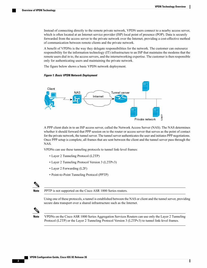
The figure below shows a basic VPDN network deployment.
Figure 1: Basic VPDN Network Deployment
A PPP client dials in to an ISP access server, called the Network Access Server (NAS). The NAS determineswhether it should forward that PPP session on to the router or access server that serves as the point of contactfor the private network, the tunnel server. The tunnel server authenticates the user and initiates PPP negotiations.Once PPP setup is complete, all frames that are sent between the client and the tunnel server pass through theNAS.
VPDNs can use these tunneling protocols to tunnel link-level frames:
• Layer 2 Tunneling Protocol (L2TP)
• Layer 2 Tunneling Protocol Version 3 (L2TPv3)
• Layer 2 Forwarding (L2F)
• Point-to-Point Tunneling Protocol (PPTP)
PPTP is not supported on the Cisco ASR 1000 Series routers.Note
Using one of these protocols, a tunnel is established between the NAS or client and the tunnel server, providingsecure data transport over a shared infrastructure such as the Internet.
VPDNs on the Cisco ASR 1000 Series Aggregation Services Routers can use only the Layer 2 TunnelingProtocol (L2TP) or the Layer 2 Tunneling Protocol Version 3 (L2TPv3) to tunnel link-level frames.
Note
VPDN Configuration Guide, Cisco IOS XE Release 3S2
VPDN Technology OverviewOverview of VPDN Technology

VPDN Terminology
VPDN Hardware DevicesGenerally three devices are involved in VPDN tunneling. Two of these devices function as tunnel endpoints--onedevice initiates the VPDN tunnel, and the other device terminates the VPDN tunnel. Depending on the tunnelingarchitecture, different types of devices can act as the local tunnel endpoint.
As new tunneling protocols have been developed for VPDNs, protocol-specific terminology has been createdto describe some of the devices that participate in VPDN tunneling. However, these devices perform the samebasic functions no matter what tunneling protocol is being used. For the sake of clarity we will use this genericterminology to refer to VPDN devices throughout this documentation:
• Client--The client device can be the PC of a dial-in user, or a router attached to a local network. Inclient-initiated VPDN tunneling scenarios, the client device acts as a tunnel endpoint.
• NAS--The network access server (NAS) is typically a device maintained by an ISP that provides VPDNservices for its customers. The NAS is the local point of contact for the client device. Establishing aconnection between the NAS and the client will referred to as receiving a calll or placing a calll,depending on whether a dial-in or dial-out scenario is being discussed. Depending on the tunnelingarchitecture, the NAS functions as follows:
• For NAS-initiated VPDN tunneling scenarios and dial-out VPDN tunneling scenarios, the NASfunctions as a tunnel endpoint. The NAS initiates dial-in VPDN tunnels and terminates dial-outVPDN tunnels. The Cisco ASR 1000 Series Aggregation Services Routers support dial-in only.
• For client-initiated VPDN tunneling scenarios, the NAS does not function as a a tunnel endpoint;it simply provides Internet connectivity.
• Tunnel server--The tunnel server is typically maintained by the customer and is the contact point for theremote private network. The tunnel server terminates dial-in VPDN tunnels and initiates dial-out VPDNtunnels.
• Tunnel server--The tunnel server is typically maintained by the customer and is the contact point for theremote private network. The tunnel server terminates dial-in VPDN tunnels and initiates dial-out VPDNtunnels.
• Tunnel switch--A tunnel switch is a device configured to perform multihop VPDN tunneling. A tunnelswitch acts as both a NAS and a tunnel server. The tunnel switch terminates incoming VPDN tunnelsand initiates the outgoing VPDN tunnels that will carry data on to the next hop.
Although technically a tunnel switch is a tunnel endpoint for both the incoming tunnel and the outgoing tunnel,for the sake of simplicity the tunnel endpoints in a multihop deployment are considered to be the device thatinitiates the first tunnel and the device that terminates the final tunnel of the multihop path.
The table below lists the generic terms and the corresponding technology-specific terms that are sometimesused to describe the NAS and the tunnel server.
VPDN Configuration Guide, Cisco IOS XE Release 3S 3
VPDN Technology OverviewVPDN Terminology

Table 1: VPDN Hardware Terminology
PPTP TermL2TP TermL2F TermGeneric Term
PPTP access concentrator(PAC)
L2TP access concentrator(LAC)
NASNAS
PPTP network server(PNS)
L2TP network server(LNS)
Home gatewayTunnel server
The Cisco ASR 1000 Series Aggregation Services Routers support only L2TP.Note
VPDN TunnelsAVPDN tunnel exists between the two tunnel endpoints. The tunnel consists of a control connection and zeroor more Layer 2 sessions. The tunnel carries encapsulated PPP datagrams and control messages between thetunnel endpoints. Multiple VPDN sessions can use the same VPDN tunnel.
VPDN SessionsA VPDN session is created between the tunnel endpoints when an end-to-end PPP connection is establishedbetween a client and the tunnel server. Datagrams related to the PPP connection are sent over the tunnel. Thereis a one-to-one relationship between an established session and the associated call. Multiple VPDN sessionscan use the same VPDN tunnel.
VPDN Architectures
Client-Initiated Dial-In VPDN TunnelingClient-initiated dial-in VPDN tunneling is also known as voluntary tunneling. In a client-initiated dial-inVPDN tunneling scenario, the client device initiates a Layer 2 tunnel to the tunnel server, and the NAS doesnot participate in tunnel negotiation or establishment. In this scenario, the NAS is not a tunnel endpoint; itsimply provides Internet connectivity. The client device must be configured to initiate the tunnel.
The main advantage of client-initiated VPDN tunneling is that it secures the connection between the clientand the ISPNAS. However, client-initiatedVPDNs are not as scalable and aremore complex thanNAS-initiatedVPDNs.
Client-initiated VPDN tunneling can use the L2TP protocol or the L2TPv3 protocol if the client device is arouter. If the client device is a PC, only the PPTP protocol is supported.
VPDN Configuration Guide, Cisco IOS XE Release 3S4
VPDN Technology OverviewVPDN Architectures

The figure below shows a client-initiated VPDN tunneling scenario.
Figure 2: Client-Initiated Dial-In VPDN Scenario
For further information about client-initiated tunneling deployments, see the “Configuring Client-InitiatedDial-In VPDN Tunneling” module.Before configuring a client-initiated dial-in VPDN tunneling deployment, you must complete the requiredtasks in the “Configuring AAA for VPDNs” module.
NAS-Initiated Dial-In VPDN TunnelingNAS-initiated dial-in VPDN tunneling is also known as compulsory tunneling. In a NAS-initiated dial-inVPDN tunneling scenario, the client dials in to the NAS through a medium that supports PPP. If the connectionfrom the client to the ISP NAS is over a medium that is considered secure, such as digital subscriber line(DSL), ISDN, or the public switched telephone network (PSTN), the client can choose not to provide additionalsecurity. The PPP session is securely tunneled from the NAS to the tunnel server without any special knowledgeor interaction required from the client.
NAS-initiated VPDN tunneling can be configured with the L2TP or L2F protocol.
The Cisco ASR 1000 Series Aggregation Services Routers support only L2TP.Note
VPDN Configuration Guide, Cisco IOS XE Release 3S 5
VPDN Technology OverviewVPDN Architectures

The figure below shows a NAS-initiated dial-in tunneling scenario.
Figure 3: NAS-Initiated Dial-In VPDN Scenario
For further information about NAS-initiated tunneling deployments, see the Configuring NAS-Initiated Dial-InVPDN Tunneling module.
Before configuring a NAS-initiated dial-in VPDN tunneling deployment, you must complete the requiredtasks in the Configuring AAA for VPDNs module.
Multihop VPDN TunnelingMultihop VPDN is a specialized VPDN configuration that allows packets to pass through multiple tunnels.Ordinarily, packets are not allowed to pass throughmore than one tunnel. In a multihop tunneling deployment,the VPDN tunnel is terminated after each hop and a new tunnel is initiated to the next hop destination. Amaximum of four hops is supported.
Multihop VPDN is required for the scenarios described in these sections:
VPDN Tunneling to an MMP Stack Group
Multihop VPDN is required when the private network uses Mutlichassis Multilink PPP (MMP) with multipletunnel servers in a stack group. Stack group configurations require the ability to establish Layer 2 tunnelsbetween participating hardware devices. If the incoming data is delivered to the stack group over a VPDNtunnel, multihop VPDN is required for the stack group to function.
Multihop VPDN tunneling with MMP can be configured using the L2TP or L2F protocol.
The Cisco ASR 1000 Aggregation Services Routers support only L2TP.Note
VPDN Configuration Guide, Cisco IOS XE Release 3S6
VPDN Technology OverviewVPDN Architectures

The figure below shows a network scenario using a multihop VPDN with an MMP deployment.
Figure 4: MMP Using Multihop VPDN
For further information about configuring multihop VPDN for MMP deployments, see the ConfiguringMultihop VPDN module.
Before configuring amultihop VPDN forMMP deployment, youmust configureMMP and youmust completethe required tasks in the Configuring AAA for VPDNs module.
Tunnel Switching VPDNs
Multihop VPDN can be used to configure a router as a tunnel switch. A tunnel switch is a device that isconfigured as both a NAS and a tunnel server. A tunnel switch is able to receive packets from an incomingVPDN tunnel and send them out over an outgoing VPDN tunnel. Tunnel switch configurations can be usedbetween ISPs to provide wholesale VPDN services.
Multihop tunnel switching can be configured using the L2TP, L2F, or PPTP protocol.
The Cisco ASR 1000 Aggregation Services Routers support only L2TP.Note
VPDN Configuration Guide, Cisco IOS XE Release 3S 7
VPDN Technology OverviewVPDN Architectures

The figure below shows a network scenario using a tunnel switching deployment.
Figure 5: Tunnel Switching Using Multihop VPDN
For further information about multihop tunnel switching deployments, see the Configuring Multihop VPDNmodule.
Before configuring a multihop tunnel switching deployment, you must complete the required tasks in theConfiguring AAA for VPDNs module.
VPDN Tunneling ProtocolsVPDNs use Layer 2 protocols to tunnel the link layer of high-level protocols (for example, PPP frames orasynchronous High-Level Data Link Control (HDLC). ISPs configure their NAS to receive calls from usersand to forward the calls to the customer tunnel server.
Usually, the ISP maintains only information about the customer tunnel server. The customer maintains theusers' IP addresses, routing, and other user database functions. Administration between the ISP and the tunnelserver is reduced to IP connectivity.
This section contains information on L2TP and L2TPv3, which are the only protocols that can be used forVPDN tunneling on the Cisco ASR 1000 Series Routers.
L2TPL2TP is an Internet Engineering Task Force (IETF) standard that combines the best features of the two oldertunneling protocols: Cisco L2F and Microsoft PPTP.
L2TP offers the same full-range spectrum of features as L2F, but offers additional functionality. AnL2TP-capable tunnel server will work with an existing L2F NAS and will concurrently support upgradedcomponents running L2TP. Tunnel servers do not require reconfiguration each time an individual NAS isupgraded from L2F to L2TP. The table below compares L2F and L2TP feature components.
VPDN Configuration Guide, Cisco IOS XE Release 3S8
VPDN Technology OverviewVPDN Tunneling Protocols

Table 2: L2F and L2TP Feature Comparison
L2TPL2FFunction
YesNoFlow Control
YesNoAttribute-value (AV) pair hiding
YesYesTunnel server load sharing
YesYesTunnel server stacking/multihopsupport
YesYesTunnel server primary andsecondary backup
YesYesDomain Name System (DNS)name support
YesYesDomain name flexibility
YesYesIdle and absolute timeout
YesYesMultilink PPP support
YesYesMultichassisMultilink PPP support
• All security benefits of PPP,including multiple per-userauthentication options:
• CHAP
• MS-CHAP
• PAP
• Tunnel authenticationoptional
• All security benefits of PPP,including multiple per-userauthentication options:
• Challenge HandshakeAuthentication Protocol(CHAP)
• Microsoft CHAP(MS-CHAP)
• PasswordAuthentication Protocol(PAP)
• Tunnel authenticationmandatory
Security
Traditional dialup networking services support only registered IP addresses, which limits the types ofapplications that are implemented over VPDNs. L2TP supports multiple protocols and unregistered andprivately administered IP addresses. This allows the existing access infrastructure--such as the Internet,modems, access servers, and ISDN terminal adapters (TAs)--to be used. It also allows customers to outsource
VPDN Configuration Guide, Cisco IOS XE Release 3S 9
VPDN Technology OverviewVPDN Tunneling Protocols

dial-out support, thus reducing overhead for hardware maintenance costs and 800 number fees, and allowsthem to concentrate corporate gateway resources.
The figure below shows the basic L2TP architecture in a typical dial-in environment.
Figure 6: L2TP Architecture
Using L2TP tunneling, an ISP or other access service can create a virtual tunnel to link remote sites or remoteusers with corporate home networks. The NAS located at the POP of the ISP exchanges PPP messages withremote users and communicates by way of L2TP requests and responses with the private network tunnel serverto set up tunnels. L2TP passes protocol-level packets through the virtual tunnel between endpoints of apoint-to-point connection. Frames from remote users are accepted by the ISP NAS, stripped of any linkedframing or transparency bytes, encapsulated in L2TP, and forwarded over the appropriate tunnel. The privatenetwork tunnel server accepts these L2TP frames, strips the L2TP encapsulation, and processes the incomingframes for the appropriate interface.
VPDN Configuration Guide, Cisco IOS XE Release 3S10
VPDN Technology OverviewVPDN Tunneling Protocols

The figure below depicts the events that occur during establishment of a NAS-initiated dial-in L2TP connection.
Figure 7: L2TP Protocol Negotiation Events
The following describes the sequence of events shown in the figure above and is keyed to the figure:
1 The remote user initiates a PPP connection to the ISP NAS using a medium that supports PPP such as theanalog telephone system. The NAS accepts the connection, the PPP link is established, and Link ControlProtocol (LCP) is negotiated.
2 After the end user and NAS negotiate LCP, the NAS partially authenticates the end user with CHAP orPAP. The username, domain name, or Dialed Number Information Service (DNIS) is used to determinewhether the user is a VPDN client. If the user is not a VPDN client, authentication continues, and theclient will access the Internet or other contacted service. If the username is a VPDN client, the mappingwill name a specific endpoint (the tunnel server).
3 The tunnel endpoints, the NAS and the tunnel server, authenticate each other before any tunnel or sessionestablishment is attempted. Alternatively, the tunnel server can accept tunnel creation without any tunnelauthentication of the NAS. The NAS and the tunnel server exchange control messages to negotiate tunnelestablishment.
4 Once the tunnel exists, an L2TP session is created for the end user. The NAS and the tunnel server exchangecall messages to negotiate session establishment.
5 The NAS will propagate the negotiated LCP options and the partially authenticated CHAP or PAPinformation to the tunnel server. The tunnel server will funnel the negotiated options and authenticationinformation directly to the virtual access interface, allowing authentication to be completed. If the optionsconfigured in the virtual template interface do not match the options negotiatedwith the NAS, the connectionwill fail and a disconnect notification will be sent to the NAS.
VPDN Configuration Guide, Cisco IOS XE Release 3S 11
VPDN Technology OverviewVPDN Tunneling Protocols

6 PPP packets are exchanged between the dial-in client and the remote tunnel server as if no intermediarydevice (the NAS) is involved.
Subsequent PPP incoming sessions (designated for the same tunnel server) do not repeat the L2TP tunnelnegotiation because the L2TP tunnel is already open.
L2TPv3L2TPv3 is an enhanced version of L2TP with the capability to tunnel any Layer 2 payload. L2TPv3 definesthe L2TP protocol for tunneling Layer 2 payloads over an IP core network using Layer 2 Virtual PrivateNetworks (VPNs).
In VPDN deployments, L2TPv3 can be used to establish a client-initiated tunnel from a local router to theremote customer network over an emulated circuit known as a pseudowire. There is one pseudowire associatedwith each L2TPv3 session.
Rather than using a VPDN group configuration, L2TPv3 uses an L2TP class configuration that is associatedwith the pseudowire. L2TPv3 pseudowires can also be used to establish L2TP tunnels by configuring an L2TPclass on the local device and an accept-dialin VPDN group on the customer network.
For detailed information about the L2TPv3 protocol, see the Additional References section.
VPDN Group Configuration ModesMany VPDN configuration tasks are performed within a VPDN group. A VPDN group can be configured tofunction either as a NAS VPDN group or as a tunnel server VPDN group, but not as both. However, anindividual router can be configured with both a NAS VPDN group and a tunnel server VPDN group.
You can configure a VPDN group as a specific type of VPDN group by issuing at least one of the commandslisted in the table below:
Table 3: VPDN Subgroup Configuration Modes
Command Mode PromptCommand ModeCommandVPDN Group Type
Router(config-vpdn-acc-in)#VPDN accept-dialinconfiguration
accept-dialintunnel server
Router(config-vpdn-req-in)#VPDN request-dialinconfiguration
request-dialinNAS
Many of the commands required to properly configure VPDN tunneling are issued in one of the VPDNsubgroup configurationmodes shown in the table below. Removing theVPDN subgroup command configurationwill remove all subordinate VPDN subgroup configuration commands as well.
Where to Go NextOnce you have identified the VPDN architecture that you want to configure and the tunneling protocol thatyou will use, you should perform the required tasks in the Configuring AAA for VPDNs module.
VPDN Configuration Guide, Cisco IOS XE Release 3S12
VPDN Technology OverviewVPDN Group Configuration Modes
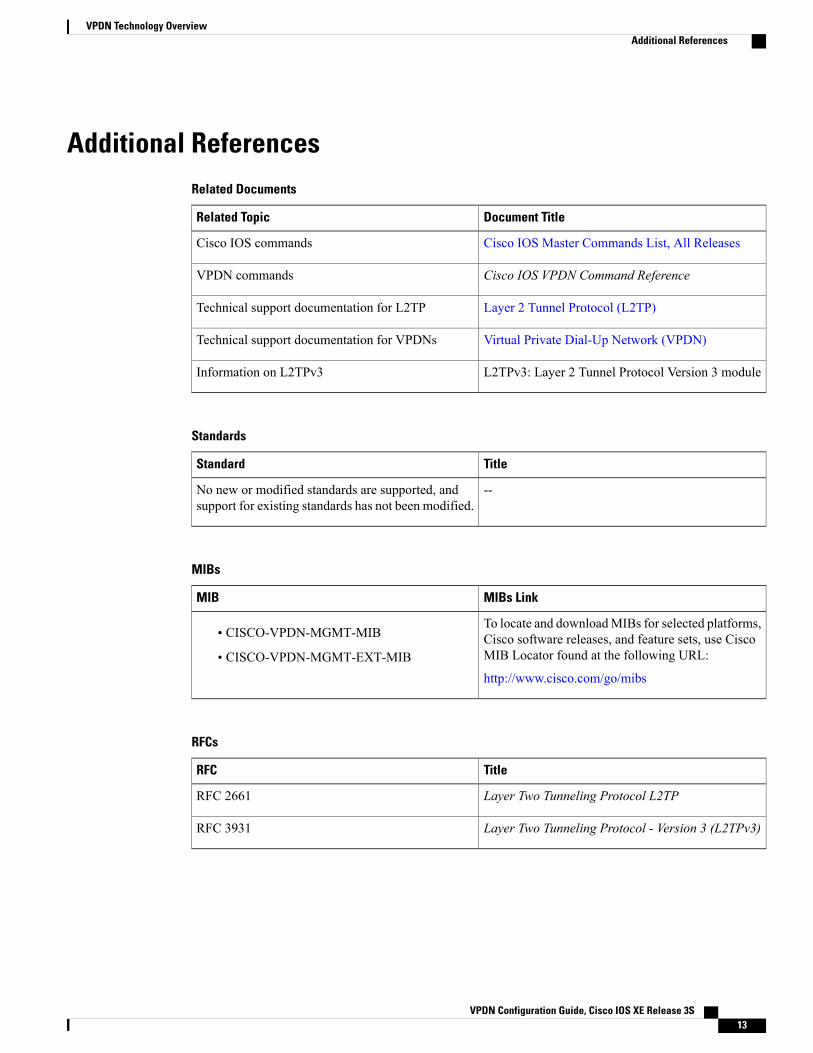
Additional ReferencesRelated Documents
Document TitleRelated Topic
Cisco IOS Master Commands List, All ReleasesCisco IOS commands
Cisco IOS VPDN Command ReferenceVPDN commands
Layer 2 Tunnel Protocol (L2TP)Technical support documentation for L2TP
Virtual Private Dial-Up Network (VPDN)Technical support documentation for VPDNs
L2TPv3: Layer 2 Tunnel Protocol Version 3 moduleInformation on L2TPv3
Standards
TitleStandard
--No new or modified standards are supported, andsupport for existing standards has not been modified.
MIBs
MIBs LinkMIB
To locate and downloadMIBs for selected platforms,Cisco software releases, and feature sets, use CiscoMIB Locator found at the following URL:
http://www.cisco.com/go/mibs
• CISCO-VPDN-MGMT-MIB
• CISCO-VPDN-MGMT-EXT-MIB
RFCs
TitleRFC
Layer Two Tunneling Protocol L2TPRFC 2661
Layer Two Tunneling Protocol - Version 3 (L2TPv3)RFC 3931
VPDN Configuration Guide, Cisco IOS XE Release 3S 13
VPDN Technology OverviewAdditional References

Technical Assistance
LinkDescription
http://www.cisco.com/cisco/web/support/index.htmlThe Cisco Support and Documentation websiteprovides online resources to download documentation,software, and tools. Use these resources to install andconfigure the software and to troubleshoot and resolvetechnical issues with Cisco products and technologies.Access to most tools on the Cisco Support andDocumentation website requires a Cisco.com user IDand password.
Feature Information for VPDN Technology OverviewThe following table provides release information about the feature or features described in this module. Thistable lists only the software release that introduced support for a given feature in a given software releasetrain. Unless noted otherwise, subsequent releases of that software release train also support that feature.
Use Cisco Feature Navigator to find information about platform support and Cisco software image support.To access Cisco Feature Navigator, go to www.cisco.com/go/cfn. An account on Cisco.com is not required.
Table 4: Feature Information for VPDN Technology Overview
Feature InformationReleasesFeature Name
This feature was introduced onCisco ASR 1000 SeriesAggregation Services Routers.
VPDNs use Layer 2 protocols totunnel the link layer of high-levelprotocols (for example, PPP framesor asynchronous HDLC). L2TP isan IETF standard that combines thebest features of the two oldertunneling protocols: Cisco L2F andMicrosoft PPTP.
No commands were introduced ormodified by this feature.
Cisco IOS XE Release 2.1
Cisco IOS XE Release 3.3S
L2TP Layer 2 Tunneling Protocol
VPDN Configuration Guide, Cisco IOS XE Release 3S14
VPDN Technology OverviewFeature Information for VPDN Technology Overview

Feature InformationReleasesFeature Name
This feature was introduced onCisco ASR 1000 SeriesAggregation Services Routers.
VPDNs securely carry private dataover a public network, allowingremote users to access a privatenetwork over a sharedinfrastructure such as the Internet.VPDNsmaintain the same securityand management policies as aprivate network, while providing acost-effective method forpoint-to-point connections betweenremote users and a central network.
No commands were introduced ormodified by this feature.
Cisco IOS XE Release 2.1Virtual Private Dial-up Network(VPDN)
VPDN Configuration Guide, Cisco IOS XE Release 3S 15
VPDN Technology OverviewFeature Information for VPDN Technology Overview

VPDN Configuration Guide, Cisco IOS XE Release 3S16
VPDN Technology OverviewFeature Information for VPDN Technology Overview

C H A P T E R 2Configuring AAA for VPDNs
This module describes how to configure authentication, authorization, and accounting (AAA) for virtualprivate dialup networks (VPDNs).
• Finding Feature Information, page 17
• Prerequisites for Configuring AAA for VPDNs, page 17
• Information About AAA for VPDNs, page 18
• How to Configure AAA for VPDNs, page 25
• Configuration Examples for AAA for VPDNs, page 80
• Where to Go Next, page 90
• Additional References, page 90
• Feature Information for AAA for VPDNs, page 92
Finding Feature InformationYour software release may not support all the features documented in this module. For the latest caveats andfeature information, see Bug Search Tool and the release notes for your platform and software release. Tofind information about the features documented in this module, and to see a list of the releases in which eachfeature is supported, see the feature information table.
Use Cisco Feature Navigator to find information about platform support and Cisco software image support.To access Cisco Feature Navigator, go to www.cisco.com/go/cfn. An account on Cisco.com is not required.
Prerequisites for Configuring AAA for VPDNs• Before configuring AAA for VPDNs, you should understand the concepts in the VPDN TechnologyOverview module.
• You must identify the VPDN architecture you plan to implement.
• You must identify the tunneling protocol you will use.
VPDN Configuration Guide, Cisco IOS XE Release 3S 17

• If you plan to configure remote AAA, you should understand the concepts in the Authentication,Authorization, and Accounting (AAA) module and Security Server Protocols module.
• If you plan to configure Layer 2 Tunneling Protocol (L2TP) Forwarding of Point-to-Point Protocol overEthernet (PPPoE) Tagging Information, it is recommended that you be familiar with RFC 2516 and DSLForum TR-101 before configuring this feature.
Information About AAA for VPDNs
VPDN Tunnel Authorization Search OrderWhen a call to a network access server (NAS) is to be tunneled to a tunnel server, the NAS must identifywhich tunnel server to forward the call to. The router can authorize users and select the outgoing tunnel basedon the domain portion of the username, the Dialed Number Identification Service (DNIS) number, the multihophostname, or any combination of these three parameters in a specified order. The default search order forVPDN tunnel authorization is to first search by DNIS, then by domain.
These sections contain information on VPDN tunnel lookup criteria:
VPDN Tunnel Lookup Based on Domain NameWhen a NAS is configured to forward VPDN calls on the basis of the user domain name, the user must usea username of the form username@domain. The NAS then compares the user domain name to the domainnames it is configured to search for. When the NAS finds a match, it forwards the user call to the proper tunnelserver.
VPDN Tunnel Lookup Based on DNIS InformationWhen a NAS is configured to forward VPDN calls on the basis of the user DNIS information, the NASidentifies the user DNIS information, which is provided on ISDN lines, and then forwards the call to theproper tunnel server.
The ability to select a tunnel on the basis of DNIS information provides additional flexibility to networkservice providers that offer VPDN services and to the companies that use the services. Instead of using onlythe domain name for tunnel selection, the NAS can use dialed number information for tunnel selection.
With this feature, a company--which might have only one domain name--can provide multiple specific phonenumbers for users to dial in to the NAS at the service provider point of presence (POP). The service providercan select the tunnel to the appropriate services or portion of the company network on the basis of the dialednumber.
VPDN Tunnel Lookup Based on Both Domain Name and DNIS InformationWhen a service provider has multiple AAA servers configured, VPDN tunnel authorization searches basedon domain name can be time consuming and might cause the client session to time out.
To provide more flexibility, service providers can configure the NAS to perform tunnel authorization searchesby domain name only, by DNIS only, or by both in a specified order.
VPDN Configuration Guide, Cisco IOS XE Release 3S18
Configuring AAA for VPDNsInformation About AAA for VPDNs

VPDN Tunnel Lookup Based on the Multihop HostnameIf a device will function as a multihop tunnel switch, tunnel authorization searches can be performed basedon the multihop hostname. Configuring a multihop hostname on a tunnel switch allows authorization searchesto be based on the identity of the peer device that initiated the tunnel. The multihop hostname can be thehostname of the remote peer that initiated the ingress tunnel, or the tunnel ID associated with the ingresstunnel.
A multihop tunnel switch can be configured to perform authorization searches by multihop hostname only,by domain name only, by DNIS only, or by any combination of these searches in a specified order.
Per-User VPDN AAAIf remote AAA is used for VPDN, the NAS that receives the call from a user forwards information about thatuser to its remote AAA server. With basic VPDN, the NAS sends the user domain name when performingauthentication based on domain name or the telephone number the user dialed in from when performingauthentication based on DNIS.
When per-user VPDN is configured, the entire structured username is sent to a RADIUS AAA server the firsttime the router contacts the AAA server. This enables the software to customize tunnel attributes for individualusers that use a common domain name or DNIS.
Without VPDN per-user configuration, the software sends only the domain name or DNIS to determine VPDNtunnel attribute information. Then, if no VPDN tunnel attributes are returned, the software sends the entireusername string.
VPDN Authorization for Directed Request UsersDirected requests allow users logging in to a NAS to select a RADIUS server for authorization. With directedrequests enabled, only the portion of the username before the “@” symbol is sent to the host specified afterthe “@” symbol. Using directed requests, authorization requests can be directed to any of the configuredservers, and only the username is sent to the specified server.
Domain Name Prefix and Suffix StrippingWhen a user connects to a NAS configured to use a remote server for AAA, the NAS forwards the usernameto the remote AAA server. Some RADIUS or TACACS+ servers require the username to be in a particularformat, which might be different from the format of the full username. For example, the remote AAA servermight require the username to be in the format [email protected], but the full username could beprefix/[email protected]@suffix. Configuring domain name stripping allows the NAS to strip incompatibleportions from the full username before forwarding the reformatted username to the remote AAA server.
The NAS can be configured to perform in these ways:
• Strip generic suffixes from the full username using the suffix delimiter character @. Any portion of thefull username that follows the first delimiter that is parsed will be stripped.
• Use a different character or set of characters as the suffix delimiter.
• Strip both suffixes and prefixes from the full username. The NAS can also be configured to strip onlyspecified suffixes instead of performing generic suffix stripping.
VPDN Configuration Guide, Cisco IOS XE Release 3S 19
Configuring AAA for VPDNsPer-User VPDN AAA

VPDN Tunnel AuthenticationVPDN tunnel authentication enables routers to authenticate the other tunnel endpoint before establishing aVPDN tunnel. VPDN tunnel authentication is optional for L2TP tunnels.
For additional information on configuring VPDN tunnel authentication for client-initiated VPDN tunnelingdeployments, see the "Configuring VPDN Tunnel Authentication" section.
VPDN tunnel authentication can be performed in these ways:
• Using local AAA on both the NAS and the tunnel server
• Using a remote RADIUS AAA server on the NAS and local AAA on the tunnel server
• Using a remote TACACS+ AAA server on the NAS and local AAA on the tunnel server
For L2TP tunnels only, a remote RADIUS AAA server can be used to perform VPDN tunnel authenticationon the VPDN tunnel terminator as follows:
• Using a remote RADIUS AAA server on the tunnel server for dial-in VPDNs
• Using a remote RADIUS AAA server on the NAS for dial-out VPDNs
For detailed information on configuring remote RADIUS or TACACS+ servers, see the "Additional Referencessection."
RADIUS Tunnel Accounting for L2TP VPDNsRADIUS tunnel accounting for VPDNs is supported by RFC 2867, which introduces six new RADIUSaccounting types. Without RADIUS tunnel accounting support, VPDN with network accounting will notreport all possible attributes to the accounting record file. RADIUS tunnel accounting support allows usersto determine tunnel-link status changes. Because all possible attributes can be displayed, users can betterverify accounting records with their Internet service providers (ISPs).
Enabling tunnel type accounting records allows the router to send tunnel and tunnel-link accounting recordsto the RADIUS server. The two types of accounting records allow the identification of VPDN tunneling eventsas described next.
Tunnel-Type Accounting Records
AAA sends Tunnel-Start, Tunnel-Stop, or Tunnel-Reject accounting records to the RADIUS server to identifythese events:
• A VPDN tunnel is brought up or destroyed.
• A request to create a VPDN tunnel is rejected.
Tunnel-Link-Type Accounting Records
AAA sends Tunnel-Link-Start, Tunnel-Link-Stop, or Tunnel-Link-Reject accounting records to the RADIUSserver to identify these events:
• A user session within a VPDN tunnel is brought up or brought down.
• A user session create request is rejected.
VPDN Configuration Guide, Cisco IOS XE Release 3S20
Configuring AAA for VPDNsVPDN Tunnel Authentication

VPDN-Specific Remote RADIUS AAA Server ConfigurationsThe RADIUS attributes are specific to VPDN configurations. For detailed information on configuring remoteRADIUS or TACACS+ servers, see the Additional References section.
VPDN-specific RADIUS attributes provide this functionality:
• Tunnel assignments--The NAS AAA server can be configured to group users from different per-user ordomain RADIUS profiles into the same active VPDN tunnel when the tunnel type and tunnel endpointare identical.
• Authentication names for NAS-initiated tunnels--The NAS AAA server can be configured withauthentication names other than the default names for the NAS and the NAS AAA server.
L2TP Forwarding of PPPoE Tagging InformationThe L2TP Forwarding of PPPoE Tag Information feature allows you to transfer DSL line information fromthe L2TP access concentrator (LAC) to the L2TP network server (LNS). For example, the LAC transportsthe actual-rate-up and the actual-rate-down PPPoE tag information to the LNS, which learns about the actualPPPoE transfer speeds that are negotiated by the customer premise equipment (CPE) and the digital subscriberline access multiplexer (DSLAM). The DSLAM inserts the PPPoE tag values for the rate up and the rate downand signals this information during PPPoE establishment with the LAC, which in turn, sends this informationto the LNS.
By using the L2TP Forwarding of PPPoE Tag Information feature, you can also override the nas-port-id orcalling-station-id VSAs, or both, on the LNS with the Circuit-ID and Remote-ID VSA respectively.
When you configure the dsl-line-info-forwarding command in VPDN group or VPDN-template configurationmode, and when the LNS receives one of the specified AV pairs, the LNS sends a matching VSA to theRADIUS server as a AAA request. The associated AAA attributes are:
• AAA_CIRCUIT_ID (RADIUS attribute 87)
• AAA_REMOTE_ID (RADIUS attribute 31)
• DSL Sync Rate VSAs
Enter the radius-server attribute 87 circuit-id command to override the nas-port-id with the CIRCUIT_IDVSA. Enter the radius-server attribute 31 remote-id command to override the calling-station-id with theREMOTE_ID VSA.
In accordance with DSL Forum 2004-71, the DSL uses the Vendor Specific tag for line identification. Thefirst 2 octets (TAG_TYPE) are PPPOE_TAG_VENDSPEC (0x0105). The next 2 octets (TAG_LENGTH)contain the total length including Sub-options, Sub-option-lengths, and Tag-values. The first four octets ofthe TAG_VALUE contain the vendor ID. The next octet contains sub-option for Agent Remote ID (0x02).Following octet contains total length of Sub-option-tag in bytes.
Themaximum length for the Remote-ID tag is 63 bytes. The Remote-ID tag contains an operator administeredstring that uniquely identifies the subscriber on the associated DSL line. The Remote-ID tag can be a phonenumber, an email address, a billing account number, or any other string that can be used by Service Providersas a tracking mechanism.
VPDN Configuration Guide, Cisco IOS XE Release 3S 21
Configuring AAA for VPDNsVPDN-Specific Remote RADIUS AAA Server Configurations

If the discovery frame has the sub-option 0x01, it indicates the presence of the Circuit-ID tag. A single framesupports Circuit-ID, Remote-ID, or both. If Circuit-ID is present in the same frame, it sends to the RADIUSserver through the Nas-Port-ID attribute.
The following example shows an access and accounting request sent to the RADIUS server with remote-IDtag and DSL-Sync-Rate tags:
01:24:52: RADIUS/ENCODE: Best Local IP-Address 10.0.73.20 for Radius-Server 128.107.164.25401:24:52: RADIUS(00000011): Send Access-Request to 192.107.164.254:1645 id 1645/3, len 39101:24:52: RADIUS: authenticator 3B 49 F5 7D 8A 6F A4 D7 - 57 99 E6 60 A9 D0 C7 B901:24:52: RADIUS: Vendor, Cisco [26] 4101:24:52: RADIUS: Cisco AVpair [1] 35 "client-mac-address=0090.bf06.c81c"01:24:52: RADIUS: Vendor, Cisco [26] 3901:24:52: RADIUS: Cisco AVpair [1] 33 "actual-data-rate-upstream=20480"01:24:52: RADIUS: Vendor, Cisco [26] 3901:24:52: RADIUS: Cisco AVpair [1] 33 "actual-data-rate-downstream=512"01:24:52: RADIUS: Vendor, Cisco [26] 3901:24:52: RADIUS: Cisco AVpair [1] 33 "minimum-data-rate-upstream=1024"01:24:52: RADIUS: Framed-Protocol [7] 6 PPP [1]01:24:52: RADIUS: User-Name [1] 16 "pshroff-client"01:24:52: RADIUS: CHAP-Password [3] 19 *01:24:52: RADIUS: NAS-Port-Type [61] 6 Ethernet [15]01:24:52: RADIUS: Vendor, Cisco [26] 4601:24:52: RADIUS: Cisco AVpair [1] 40 "circuit-id-tag=Ethernet1/0.1:ababababa"01:24:52: RADIUS: Vendor, Cisco [26] 3601:24:52: RADIUS: Cisco AVpair [1] 30 "remote-id-tag=0090.bf06.c81c"01:24:52: RADIUS: NAS-Port [5] 6 26843548601:24:52: RADIUS: NAS-Port-Id [87] 25 "Ethernet1/0.1:ababababa"01:24:52: RADIUS: Vendor, Cisco [26] 4101:24:52: RADIUS: Cisco AVpair [1] 35 "client-mac-address=0090.bf06.c81c"01:24:52: RADIUS: Service-Type [6] 6 Framed [2]01:24:52: RADIUS: NAS-IP-Address [4] 6 10.0.73.2001:24:55: RADIUS(00000011): Send Accounting-Request to 192.107.164.254:1646 id 1646/4, len49501:24:55: RADIUS: authenticator 22 6F B2 F3 88 B1 03 91 - 4A 70 53 BD 44 A6 A6 0F01:24:55: RADIUS: Acct-Session-Id [44] 19 "1/0/0/30_00000008"01:24:55: RADIUS: Vendor, Cisco [26] 3901:24:55: RADIUS: Cisco AVpair [1] 33 "actual-data-rate-upstream=20480"01:24:55: RADIUS: Vendor, Cisco [26] 3901:24:55: RADIUS: Cisco AVpair [1] 33 "actual-data-rate-downstream=512"01:24:55: RADIUS: Vendor, Cisco [26] 3901:24:55: RADIUS: Cisco AVpair [1] 33 "minimum-data-rate-upstream=1024"01:24:55: RADIUS: Vendor, Cisco [26] 4901:24:55: RADIUS: Cisco AVpair [1] 43 "minimum-data-rate-downstream-low-power=32"01:24:55: RADIUS: Vendor, Cisco [26] 4601:24:55: RADIUS: Cisco AVpair [1] 40 "maximum-interleaving-delay-upstream=64"01:24:55: RADIUS: Framed-Protocol [7] 6 PPP [1]01:24:55: RADIUS: User-Name [1] 16 "pshroff-client"01:24:55: RADIUS: Vendor, Cisco [26] 3201:24:55: RADIUS: Cisco AVpair [1] 26 "connect-progress=Call Up"01:24:55: RADIUS: Acct-Authentic [45] 6 RADIUS [1]01:24:55: RADIUS: Acct-Status-Type [40] 6 Start [1]01:24:55: RADIUS: NAS-Port-Type [61] 6 Ethernet [15]01:24:55: RADIUS: Vendor, Cisco [26] 4601:24:55: RADIUS: Cisco AVpair [1] 40 "circuit-id-tag=Ethernet1/0.1:ababababa"01:24:55: RADIUS: Vendor, Cisco [26] 3601:24:55: RADIUS: Cisco AVpair [1] 30 "remote-id-tag=0090.bf06.c81c"01:24:55: RADIUS: NAS-Port [5] 6 26843548601:24:55: RADIUS: NAS-Port-Id [87] 25 "Ethernet1/0.1:ababababa"01:24:55: RADIUS: Vendor, Cisco [26] 4101:24:55: RADIUS: Cisco AVpair [1] 35 "client-mac-address=0090.bf06.c81c"01:24:55: RADIUS: Service-Type [6] 6 Framed [2]01:24:55: RADIUS: NAS-IP-Address [4] 6 10.0.73.2001:24:55: RADIUS: Acct-Delay-Time [41] 6 001:24:57: RADIUS: Received from id 1646/4 192.107.164.254:1646, Accounting-response, len20The LAC sends the indicated AV pairs, containing the DSL line information to the LNS, which sends themthrough AAA to the RADIUS server. The RADIUS server uses the DSL line identification when processingAAA requests.
VPDN Configuration Guide, Cisco IOS XE Release 3S22
Configuring AAA for VPDNsL2TP Forwarding of PPPoE Tagging Information

If you plan to configure L2TP Forwarding of PPPoE Tagging Information, it is recommended that you befamiliar with RFC 2516 and DSL Forum TR-101 before configuring this feature.
DSL Sync-Rate VSAsThe DSL uses PPPoE Vendor Specific tags for Sync-Rate tag information. DSL Sync-Rates are encoded as32-bit binary values, describing the rate in kbps. The tag length is 4 bytes. The table below shows the mandatoryDSL Sync-Rate tags and their associated RADIUS VSA.
Table 5: Required DSL Sync-Rate Tags
DescriptionRADIUS VSADSL Line Information
Actual data rate upstream in kbps.AAA_AT_ACTUAL_RATE_UPDSL Line Actual-Data-Rate-UpstreamAVP
Actual data rate downstream in kbps.AAA_AT_ACTUAL_RATE_DOWNDSL Line Actual-Data-Rate-DownstreamAVP
Minimum data rate upstream in kbps.AAA_AT_MIN_RATE_UPDSL Line Minimum-Data-Rate-UpstreamAVP
Minimum data rate downstream in kbps.AAA_AT_MIN_RATE_DOWNDSL LineMinimum-Data-Rate-Downstream AVP
PADI/PADR framesmight contain an optional DSL Sync-Rate tag. The table below showsDSL line informationand their associated RADIUS VSA for the optional DSL Sync-Rate tags.
Table 6: Optional DSL Sync-Rate Tags
DescriptionRADIUS VSADSL Line Information
Attainable data rate upstream in kbps.AAA_AT_ATTAINABLE_RATE_UPDSL Line Attainable-Data-Rate-UpstreamAVP
Attainable data rate downstream in kbps.AAA_AT_ATTAINABLE_RATE_DOWNDSL LineAttainable-Data-Rate-Downstream AVP
Maximum data rate upstream in kbps.AAA_AT_MAX_RATE_UPDSL LineMaximum-Data-Rate-UpstreamAVP
Maximum data rate downstream in kbps.AAA_AT_MAX_RATE_DOWNDSL LineMaximum-Data-Rate-Downstream AVP
Minimum data rate upstream in low powerstate in kbps.
AAA_AT_MIN_RATE_UP_LOW_POWERDSL Line Minimum-Data-Rate-Upstream-Low-Power AVP
Minimum data rate downstream in lowpower state in kbps.
AAA_AT_MIN_RATE_DOWN_LOW_POWERDSL LineMinimum-Data-Rate-Downstream-Low-Power AVP
VPDN Configuration Guide, Cisco IOS XE Release 3S 23
Configuring AAA for VPDNsL2TP Forwarding of PPPoE Tagging Information
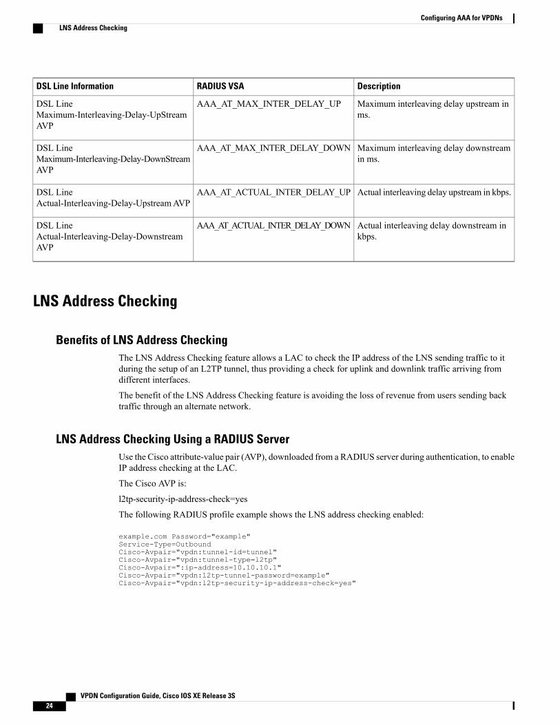
DescriptionRADIUS VSADSL Line Information
Maximum interleaving delay upstream inms.
AAA_AT_MAX_INTER_DELAY_UPDSL LineMaximum-Interleaving-Delay-UpStreamAVP
Maximum interleaving delay downstreamin ms.
AAA_AT_MAX_INTER_DELAY_DOWNDSL LineMaximum-Interleaving-Delay-DownStreamAVP
Actual interleaving delay upstream in kbps.AAA_AT_ACTUAL_INTER_DELAY_UPDSL LineActual-Interleaving-Delay-UpstreamAVP
Actual interleaving delay downstream inkbps.
AAA_AT_ACTUAL_INTER_DELAY_DOWNDSL LineActual-Interleaving-Delay-DownstreamAVP
LNS Address Checking
Benefits of LNS Address CheckingThe LNS Address Checking feature allows a LAC to check the IP address of the LNS sending traffic to itduring the setup of an L2TP tunnel, thus providing a check for uplink and downlink traffic arriving fromdifferent interfaces.
The benefit of the LNS Address Checking feature is avoiding the loss of revenue from users sending backtraffic through an alternate network.
LNS Address Checking Using a RADIUS ServerUse the Cisco attribute-value pair (AVP), downloaded from a RADIUS server during authentication, to enableIP address checking at the LAC.
The Cisco AVP is:
l2tp-security-ip-address-check=yes
The following RADIUS profile example shows the LNS address checking enabled:
example.com Password="example"Service-Type=OutboundCisco-Avpair="vpdn:tunnel-id=tunnel"Cisco-Avpair="vpdn:tunnel-type=l2tp"Cisco-Avpair=":ip-address=10.10.10.1"Cisco-Avpair="vpdn:l2tp-tunnel-password=example"Cisco-Avpair="vpdn:l2tp-security-ip-address-check=yes"
VPDN Configuration Guide, Cisco IOS XE Release 3S24
Configuring AAA for VPDNsLNS Address Checking

Debugging Dropped Control PacketsUse the LNS Address Checking feature to help troubleshoot dropped control packets. If you configure thedebug vpdn 12x-error command, informational messages display for each control packet that is dropped inthe following format:
Tnl <tunnel-ID>L2TP: Drop <L2TP-packet-name>from y.y.y.y (attempted) x.x.x.x
Modified LNS Dead-Cache HandlingTheModified LNS Dead-Cache Handling feature allows you to display and clear (restart) any Layer 2 TunnelProtocol (L2TP) network server (LNS) entry in a dead-cache (DOWN) state. You can use this feature togenerate a Simple Network Management Protocol (SNMP) or system message log (syslog) event when anLNS enters or exits a dead-cache state. Once an LNS exits the dead-cache state, the LNS is able to establishnew sessions.
Prior to Cisco IOS XE Release 2.4, networks could not identify the status of a Load Sharing Group (LSG) ona LAC. As a result, it was not possible to know if an LNS is not responding (dead-cache state). An LNS in adead-cache state causes an LSG to reject a call from an LAC.
Networks also have no method of logging, either though a syslog or SNMP event, when an LNS enters, or iscleared from a dead-cache state.
TheModified LNSDead-Cache Handling feature allows you to view (identify) and clear (restart) one or moreLNS entries in a dead-cache (DOWN) state, and generate either a syslog or SNMP event when an LNS exitsor enters a dead-cache state. Once an LNS clears a dead-cache state, the LNS is active and available for newcall-session establishments.
How to Configure AAA for VPDNs
Enabling VPDN on the NAS and the Tunnel ServerBefore performing any VPDN configuration tasks, you must enable VPDN on the NAS and the tunnel server.If you are deploying a multihop VPDN tunnel switching architecture, VPDN must be enabled on the tunnelswitch as well.
SUMMARY STEPS
1. enable2. configure terminal3. vpdn enable
VPDN Configuration Guide, Cisco IOS XE Release 3S 25
Configuring AAA for VPDNsModified LNS Dead-Cache Handling

DETAILED STEPS
PurposeCommand or Action
Enables privileged EXEC mode.enableStep 1
Example:
Router> enable
• Enter your password if prompted.
Enters global configuration mode.configure terminal
Example:
Router# configure terminal
Step 2
Enables VPDN on the router.vpdn enable
Example:
Router(config)# vpdn enable
Step 3
Configuring the VPDN Tunnel Authorization Search OrderPerform this task on the NAS or the tunnel switch to configure the VPDN tunnel authorization search orderif you prefer to use an order other than the default order. The default search order for VPDN tunnel authorizationis to first search by DNIS, then by domain.
Before You Begin
You must perform the task in the "Enabling VPDN on the NAS and the Tunnel Server" section.
Tunnel authorization searches based on the multihop hostname are supported only for multihop tunnelswitching deployments.
Note
SUMMARY STEPS
1. enable2. configure terminal3. vpdn search-order {dnis [domain] [multihop-hostname] | domain [dnis] [multihop-hostname] |
multihop-hostname [dnis] [domain]}
VPDN Configuration Guide, Cisco IOS XE Release 3S26
Configuring AAA for VPDNsConfiguring the VPDN Tunnel Authorization Search Order

DETAILED STEPS
PurposeCommand or Action
Enables privileged EXEC mode.enableStep 1
Example:
Router> enable
• Enter your password if prompted.
Enters global configuration mode.configure terminal
Example:
Router# configure terminal
Step 2
Specifies how the service provider NAS or tunnel switch is toperform VPDN tunnel authorization searches.
vpdn search-order {dnis [domain][multihop-hostname] | domain [dnis]
Step 3
[multihop-hostname] |multihop-hostname [dnis][domain]} • At least one search parameter keywordmust be specified. You
can specify multiple search parameter keywords in any orderto define the desired order in which searches will be performed.
Example:
Router(config)# vpdn search-order domaindnis
Themultihop-hostname keyword is used only on a deviceconfigured as a tunnel switch.
Note
Configuring per-User VPDN on the NASPer-user VPDN can be configured globally, or for individual VPDN groups. The VPDN group configurationwill take precedence over the global configuration.
Perform one of these tasks on the NAS to configure per-user VPDN:
PrerequisitesThe NAS remote RADIUS server must be configured for AAA. See the "Additional References" section.
Restrictions• Per-user VPDN configuration supports only RADIUS as the AAA protocol.
• This task is compatible only with NAS-initiated dial-in VPDN scenarios.
Configuring Global per-User VPDNConfiguring per-user VPDN on a NAS causes the NAS to send the entire structured username of the user toa RADIUS AAA server the first time the NAS contacts the AAA server. Per-user VPDN can be configured
VPDN Configuration Guide, Cisco IOS XE Release 3S 27
Configuring AAA for VPDNsConfiguring per-User VPDN on the NAS

globally, or for individual VPDN groups. Configuring per-user VPDN globally will apply per-user VPDN toall request-dialin VPDN groups configured on the NAS.
Perform this task on the NAS to configure global per-user VPDN.
SUMMARY STEPS
1. enable2. configure terminal3. vpdn authen-before-forward
DETAILED STEPS
PurposeCommand or Action
Enables privileged EXEC mode.enableStep 1
Example:
Router> enable
• Enter your password if prompted.
Enters global configuration mode.configure terminal
Example:
Router# configure terminal
Step 2
Configures a NAS to request authentication of a completeusername before making a forwarding decision for dial-intunnels.
vpdn authen-before-forward
Example:
Router(config)# vpdn authen-before-forward
Step 3
Configuring per-User VPDN for a VPDN GroupConfiguring per-user VPDN on a NAS causes the NAS to send the entire structured username of the user toa RADIUS AAA server the first time the NAS contacts the AAA server. Per-user VPDN can be configuredglobally, or for individual VPDN groups. Configuring per-user VPDN at the VPDN group level will applyper-user VPDN only to calls associated with that specific VPDN group
Perform this task on the NAS to configure per-user VPDN for a specific VPDN group.
VPDN Configuration Guide, Cisco IOS XE Release 3S28
Configuring AAA for VPDNsConfiguring per-User VPDN on the NAS

SUMMARY STEPS
1. enable2. configure terminal3. vpdn-group name4. request-dialin5. protocol l2tp6. exit7. authen-before-forward
DETAILED STEPS
PurposeCommand or Action
Enables privileged EXEC mode.enableStep 1
Example:
Router> enable
• Enter your password if prompted.
Enters global configuration mode.configure terminal
Example:
Router# configure terminal
Step 2
Creates a VPDN group and enters VPDN group configurationmode.
vpdn-group name
Example:
Router(config)# vpdn-group 1
Step 3
Configures a NAS to request the establishment of an L2TP tunnelto a tunnel server, creates a request-dialin VPDN subgroup, andenters VPDN request dial-in subgroup configuration mode.
request-dialin
Example:
Router(config-vpdn)# request-dialin
Step 4
Specifies the Layer 2 tunneling protocol that the VPDN groupwill use.
protocol l2tp
Example:
Router(config-vpdn-req-in)# protocol l2tp
Step 5
Exits to VPDN group configuration mode.exit
Example:
Router(config-vpdn-req-in)# exit
Step 6
VPDN Configuration Guide, Cisco IOS XE Release 3S 29
Configuring AAA for VPDNsConfiguring per-User VPDN on the NAS
PurposeCommand or Action
Configures a NAS to request authentication of a completeusername before making a forwarding decision for dial-in L2TPtunnels belonging to a VPDN group.
authen-before-forward
Example:
Router(config-vpdn)# authen-before-forward
Step 7
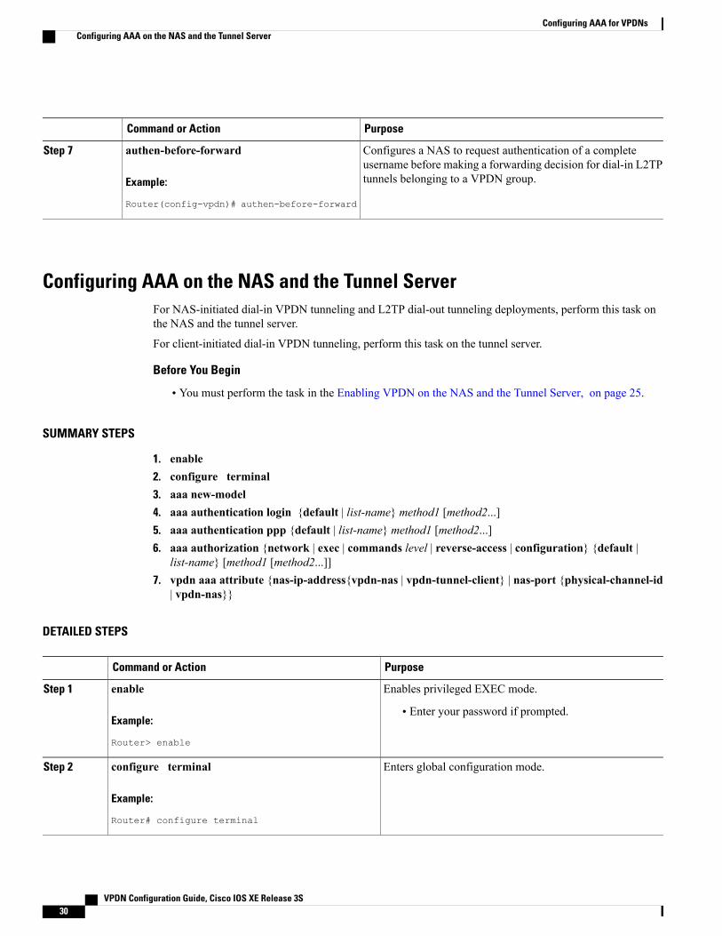
Configuring AAA on the NAS and the Tunnel ServerFor NAS-initiated dial-in VPDN tunneling and L2TP dial-out tunneling deployments, perform this task onthe NAS and the tunnel server.
For client-initiated dial-in VPDN tunneling, perform this task on the tunnel server.
Before You Begin
• You must perform the task in the Enabling VPDN on the NAS and the Tunnel Server, on page 25.
SUMMARY STEPS
1. enable2. configure terminal3. aaa new-model4. aaa authentication login {default | list-name} method1 [method2...]5. aaa authentication ppp {default | list-name} method1 [method2...]6. aaa authorization {network | exec | commands level | reverse-access | configuration} {default |
list-name} [method1 [method2...]]7. vpdn aaa attribute {nas-ip-address{vpdn-nas | vpdn-tunnel-client} | nas-port {physical-channel-id
| vpdn-nas}}
DETAILED STEPS
PurposeCommand or Action
Enables privileged EXEC mode.enableStep 1
Example:
Router> enable
• Enter your password if prompted.
Enters global configuration mode.configure terminal
Example:
Router# configure terminal
Step 2
VPDN Configuration Guide, Cisco IOS XE Release 3S30
Configuring AAA for VPDNsConfiguring AAA on the NAS and the Tunnel Server

PurposeCommand or Action
Enables the AAA access control model.aaa new-model
Example:
Router(config)# aaa new model
Step 3
Sets AAA authentication at login.aaa authentication login {default | list-name}method1[method2...]
Step 4
Example:
Router(config)# aaa authentication login defaultlocal
Specifies one or more AAA authentication methods for useon serial interfaces that are running PPP.
aaa authentication ppp {default | list-name} method1[method2...]
Step 5
Example:
Router(config)# aaa authentication ppp defaultradius
This command must be configured with theif-needed option for the method1argument if youare configuring shell-based authentication forVPDNs. This configures PPP to bypass userauthentication if the user has been authenticated atthe login prompt.
Note
Sets parameters that restrict user access to a network.aaa authorization {network | exec | commands level |reverse-access | configuration} {default | list-name}[method1 [method2...]]
Step 6
Example:
Router(config)# aaa authorization network defaultradius
(Optional) Enables AAA attributes related to a VPDN thatwill be reported to the AAA server in accounting records.
vpdn aaa attribute {nas-ip-address{vpdn-nas |vpdn-tunnel-client} | nas-port {physical-channel-id |vpdn-nas}}
Step 7
Configure this command only on the tunnel serverwhen remote AAA accounting will be enabled onthe NAS.
Note
Example:
Router(config)# vpdn aaa attribute nas-ip-addressvpdn-nas
Configuring Remote AAA for VPDNsA remote RADIUS or TACACS+ AAA server can be used for tunnel authentication. For detailed informationon configuring remote RADIUS or TACACS+ servers, see the "Additional References" section.
Remote AAA authentication can be configured on the NAS or the tunnel server in these ways:
VPDN Configuration Guide, Cisco IOS XE Release 3S 31
Configuring AAA for VPDNsConfiguring Remote AAA for VPDNs

Dial-In Configurations
• The NAS can be configured to use a remote AAA server.
• The tunnel server, functioning as the tunnel terminator, can be configured to use a remote AAA serverfor L2TP tunnels only.
Dial-Out Configurations
• The NAS, functioning as the tunnel terminator, can be configured to use a remote AAA server for L2TPtunnels only.
Perform one of these tasks to configure remote AAA for VPDNs:
Configuring the NAS for Remote AAA for Dial-In VPDNsPerform this task to configure the NAS to use a remote RADIUS or TACACS+ server for tunnel authentication.This task applies only to dial-in VPDN configurations.
Before You Begin
SUMMARY STEPS
1. enable2. configure terminal3. Do one of the following:
• radius-server host {hostname | ip-address} [auth-port port-number] [acct-port port-number][timeout seconds] [retransmit retries] [key string] [alias {hostname | ip-address}]
• tacacs-server host {host-name | host-ip-address} [key string] [nat] [port [integer]][single-connection] [timeout [integer]]
4. Do one of the following:
• aaa group server radius group-name
• aaa group server tacacs+ group-name
5. Do one of the following:
• server ip-address [auth-port port-number] [acct-port port-number]
• server ip-address
DETAILED STEPS
PurposeCommand or Action
Enables privileged EXEC mode.enableStep 1
VPDN Configuration Guide, Cisco IOS XE Release 3S32
Configuring AAA for VPDNsConfiguring Remote AAA for VPDNs

PurposeCommand or Action
Example:
Router> enable
• Enter your password if prompted.
Enters global configuration mode.configure terminal
Example:
Router# configure terminal
Step 2
Specifies a RADIUS server host.Do one of the following:Step 3
or• radius-server host {hostname | ip-address} [auth-portport-number] [acct-port port-number] [timeout seconds] Specifies a TACACS+ host.[retransmit retries] [key string] [alias {hostname |ip-address}]
• tacacs-server host {host-name | host-ip-address} [keystring] [nat] [port [integer]] [single-connection] [timeout[integer]]
Example:
Router(config)# radius-server host 10.1.1.1
Example:
Router(config)# tacacs-server host 10.2.2.2
(Optional) Groups different RADIUS server hosts intodistinct lists and distinct methods and enters RADIUSserver group configuration mode.
Do one of the following:Step 4
• aaa group server radius group-name
• aaa group server tacacs+ group-name or
(Optional) Groups different TACACS+ server hosts intodistinct lists and distinct methods and enters RADIUSserver group configuration mode.Example:
Router(config)# aaa group server radius group1
Example:
Router(config)# aaa group server tacacs+ group7
(Optional) Configures the IP address of the RADIUSserver for the group server.
Do one of the following:Step 5
• server ip-address [auth-port port-number] [acct-portport-number] or
(Optional) Configures the IP address of the TACACS+server for the group server.
• server ip-address
VPDN Configuration Guide, Cisco IOS XE Release 3S 33
Configuring AAA for VPDNsConfiguring Remote AAA for VPDNs

PurposeCommand or Action
Example:
Router(config-sg-radius)# server 10.1.1.1 auth-port1000 acct-port 1646
Perform this step multiple times to configuremultiple RADIUS or TACACS+ servers as partof the server group.
Note
Example:
Router(config-sg-radius)# server 10.2.2.2
What to Do Next
You must perform the process in the Configuring VPDN Tunnel Authentication section.
Configuring the Tunnel Terminator for Remote RADIUS AAA for L2TP TunnelsYou can configure the device that terminates the L2TP VPDN tunnel to perform remote RADIUS AAA.Without this functionality, the tunnel terminator can only perform L2TP authentication locally. Localauthentication requires that data about the corresponding tunnel endpoint be configured within a VPDN group.This mechanism does not scale well because the information stored in the VPDN groups on each device mustbe updated independently.
Remote RADIUS authentication allows users to store configurations on the RADIUS server, avoiding theneed to store information locally. New information can be added to the RADIUS server as needed, and agroup of tunnel terminators can access a common database on the RADIUS server.
Perform this task to configure remote RADIUS AAA for L2TP tunnels on the tunnel terminator. This taskcan be performed on the tunnel server for dial-in VPDN tunnels, or on the NAS for dial-out VPDN tunnels.
Before You Begin
• The remote RADIUS AAA server must be configured. For more information on configuring remoteRADIUS AAA servers, see the "Additional References" section.
• AAA must be enabled. To enable AAA, perform the task in the "Configuring AAA on the NAS and theTunnel Server" section.
VPDN Configuration Guide, Cisco IOS XE Release 3S34
Configuring AAA for VPDNsConfiguring Remote AAA for VPDNs

SUMMARY STEPS
1. enable2. configure terminal3. radius-server host {hostname | ip-address} [auth-port port-number] [acct-port port-number] [timeout
seconds] [retransmit retries] [key string] [alias {hostname | ip-address}]4. aaa group server radius group-name5. server ip-address [auth-port port-number] [acct-port port-number]6. exit7. vpdn tunnel authorization network {list-name | default}8. vpdn tunnel authorization virtual-template vtemplate-number9. vpdn tunnel authorization password password
DETAILED STEPS
PurposeCommand or Action
Enables privileged EXEC mode.enableStep 1
Example:
Router> enable
• Enter your password if prompted.
Enters global configuration mode.configure terminal
Example:
Router# configure terminal
Step 2
Specifies a RADIUS server host.radius-server host {hostname | ip-address} [auth-portport-number] [acct-port port-number] [timeout
Step 3
seconds] [retransmit retries] [key string] [alias{hostname | ip-address}]
Example:
Router(config)# radius-server host 10.1.1.1
Groups different RADIUS server hosts into distinct lists anddistinct methods and enters RADIUS server groupconfiguration mode.
aaa group server radius group-name
Example:
Router(config)# aaa group server radius group1
Step 4
Configures the IP address of the RADIUS server for the groupserver.
server ip-address [auth-port port-number] [acct-portport-number]
Step 5
VPDN Configuration Guide, Cisco IOS XE Release 3S 35
Configuring AAA for VPDNsConfiguring Remote AAA for VPDNs

PurposeCommand or Action
Example:
Router(config-sg-radius)# server 10.1.1.1auth-port 1000 acct-port 1646
Perform this step multiple times to configure multipleRADIUS or TACACS+ servers as part of the servergroup.
Note
Exits RADIUS server group configuration mode.exit
Example:
Router(config-sg-radius)# exit
Step 6
Specifies the AAA authorization method list that will be usedfor remote tunnel hostname-based authorization.
vpdn tunnel authorization network {list-name |default}
Step 7
Example:
Router(config)# vpdn tunnel authorizationnetwork default
• If the list-name argument was specified in the aaaauthorization command, you must use that list name.
• If the default keyword was specified in the aaaauthorization command, you must use that keyword.
(Optional) Selects the default virtual template from which toclone virtual access interfaces.
vpdn tunnel authorization virtual-templatevtemplate-number
Example:
Router(config)# vpdn tunnel authorizationvirtual-template 3
Step 8
(Optional) Configures a false password for the RADIUSauthorization request to retrieve the tunnel configuration thatis based on the remote tunnel hostname.
vpdn tunnel authorization password password
Example:
Router(config)# vpdn tunnel authorizationpassword my-secret
Step 9
If this command is not enabled, the password willalways be "cisco."
Note
What to Do Next
You must perform the task in the “Configuring the Multihop Tunnel Switch to Initiate Outgoing VPDNTunnels” section.
VPDN Configuration Guide, Cisco IOS XE Release 3S36
Configuring AAA for VPDNsConfiguring Remote AAA for VPDNs

Verifying and Troubleshooting Remote AAA Configurations
Verifying that the VPDN Tunnel Is Up
SUMMARY STEPS
1. enable2. show vpdn tunnel
DETAILED STEPS
Step 1 enableEnter this command to enable privileged EXEC mode. Enter your password if prompted:
Example:
Router> enable
Step 2 show vpdn tunnelEnter this command to display information about active VPDN tunnels. At least one tunnel and one session must be setup.
Example:
Router# show vpdn tunnelL2TP Tunnel and Session Information Total tunnels 1 sessions 1LocID RemID Remote Name State Remote Address Port Sessions VPDN Group4571 61568 csidtw13 est 10.0.195.4 1701 1 ?LocID RemID TunID Intf Username State Last Chg4 11 4571 Vi4.1 [email protected] est 00:02:29%No active PPPoE tunnels
Verifying the Remote RADIUS AAA Server ConfigurationPerform this task to verify that the remote AAA authorization server is configured on the tunnel endpoint andthat the tunnel endpoint can receive attributes 90 and 69 from the RADIUS server.
In this example the steps are performed on the tunnel server, which is performing remote RADIUS AAA asa tunnel terminator. These steps can also be performed on the NAS when remote RADIUS AAA is beingperformed on the NAS as a tunnel initiator for dial-in VPDNs or as a tunnel terminator for dial-out VPDNs.
SUMMARY STEPS
1. enable2. debug radius3. show logging
VPDN Configuration Guide, Cisco IOS XE Release 3S 37
Configuring AAA for VPDNsVerifying and Troubleshooting Remote AAA Configurations

DETAILED STEPS
Step 1 enableEnter this command to enable privileged EXEC mode. Enter your password if prompted:
Example:
Router> enable
Step 2 debug radiusEnter this command on the tunnel server to display RADIUS debugging messages.
Example:
Router# debug radius
Step 3 show loggingEnter this command on the tunnel server to display the contents of the standard system logging message buffer. Ensurethat "access-accept" is in the output and that attributes 90 and 69 can be seen in the RADIUS reply, as shown in bold.
Example:
Router# show logging00:32:56: RADIUS: Received from id 21645/5 172.19.192.50:1645, Access-Accept, len 8100:32:56: RADIUS: authenticator 73 2B 1B C2 33 71 93 19 - 62 AC 3E BE 0D 13 14 8500:32:56: RADIUS: Service-Type [6] 6 Outbound [5]00:32:56: RADIUS: Tunnel-Type [64] 6 00:L2TP [3]00:32:56: RADIUS: Tunnel-Medium-Type [65] 6 00:IPv4 [1]00:32:56: RADIUS: Tunnel-Client-Auth-I[90]6 00:"csidtw13"
00:32:56: RADIUS: Tunnel-Password [69]8 *00:32:56: RADIUS: Vendor, Cisco [26] 2900:32:56: RADIUS: Cisco AVpair [1] 23 "vpdn:vpdn-vtemplate=1"
Verifying the Remote TACACS+ AAA Server Configuration on the NASPerform this task on the NAS to verify that the remote TACACS+ AAA server is properly configured.
Before You Begin
Enable these debug commands before performing this task:
• debug aaa accounting --Displays information on accountable events as they occur.
• debug aaa authentication --Displays information on AAA TACACS+ authentication.
• debug aaa authorization --Displays information on AAA TACACS+ authorization.
• debug tacacs --Displays information associated with TACACS+.
• debug vpdn error --Displays information about Layer 2 protocol-independent errors that occur.
VPDN Configuration Guide, Cisco IOS XE Release 3S38
Configuring AAA for VPDNsVerifying and Troubleshooting Remote AAA Configurations

• debug vpdn events --Displays information about Layer 2 protocol-independent events that are part ofnormal tunnel establishment or shutdown.
• debug vpdn l2x-errors --Displays information about Layer 2 protocol-specific errors that are part ofnormal PPP tunnel establishment or shutdown.
• debug vpdn l2x-events --Displays information about Layer 2 protocol-specific events that are part ofnormal PPP tunnel establishment or shutdown.
• debug vpdn l2x-packets --Displays information about Layer 2 protocol-specific
• debug vtemplate --Displays cloning information for a virtual access interface from the time it is clonedfrom a virtual template to the time the virtual access interface comes down when the call ends.
SUMMARY STEPS
1. enable2. show debugging3. Examine the debug output.
DETAILED STEPS
Step 1 enableEnter this command to enable privileged EXEC mode. Enter your password if prompted:
Example:
Router> enable
Step 2 show debuggingEnter this command to display information about the types of debugging that are enabled for your router.
Example:
Router# show debuggingGeneral OS:AAA Authentication debugging is onAAA Authorization debugging is onAAA Accounting debugging is onVPN:L2X protocol events debugging is onL2X protocol errors debugging is onVPDN events debugging is onVPDN errors debugging is onVTEMPLATE:Virtual Template debugging is on!
Step 3 Examine the debug output.The following example shows complete debug output from the NAS for successful VPDN tunnel establishment usingremote TACACS+ AAA authentication at the NAS:
Example:
Jan 30 12:17:09: As1 AAA/AUTHOR/FSM: (0): LCP succeeds trivially
VPDN Configuration Guide, Cisco IOS XE Release 3S 39
Configuring AAA for VPDNsVerifying and Troubleshooting Remote AAA Configurations

20:03:18: %LINK-3-UPDOWN: Interface Async1, changed state to upJan 30 12:17:09: As1 VPDN: Looking for tunnel -- rtp.cisco.com --Jan 30 12:17:09: AAA: parse name=Async1 idb type=10 tty=1Jan 30 12:17:09: AAA: name=Async1 flags=0x11 type=4 shelf=0 slot=0 adapter=0port=1 channel=0Jan 30 12:17:09: AAA/AUTHEN: create_user (0x278B90) user='rtp.cisco.com'ruser=''port='Async1' rem_addr='' authen_type=NONE service=LOGIN priv=0Jan 30 12:17:09: AAA/AUTHOR/VPDN (898425447): Port='Async1' list='default'service=NETJan 30 12:17:09: AAA/AUTHOR/VPDN: (898425447) user='rtp.cisco.com'Jan 30 12:17:09: AAA/AUTHOR/VPDN: (898425447) send AV service=pppJan 30 12:17:09: AAA/AUTHOR/VPDN: (898425447) send AV protocol=vpdnJan 30 12:17:09: AAA/AUTHOR/VPDN (898425447) found list "default"Jan 30 12:17:09: AAA/AUTHOR/VPDN: (898425447) Method=TACACS+Jan 30 12:17:09: AAA/AUTHOR/TAC+: (898425447): user=rtp.cisco.comJan 30 12:17:09: AAA/AUTHOR/TAC+: (898425447): send AV service=pppJan 30 12:17:09: AAA/AUTHOR/TAC+: (898425447): send AV protocol=vpdnJan 30 12:17:09: TAC+: (898425447): received author response status = PASS_ADDJan 30 12:17:09: AAA/AUTHOR (898425447): Post authorization status = PASS_ADDJan 30 12:17:09: AAA/AUTHOR/VPDN: Processing AV service=pppJan 30 12:17:09: AAA/AUTHOR/VPDN: Processing AV protocol=vpdnJan 30 12:17:09: AAA/AUTHOR/VPDN: Processing AV tunnel-type=l2tpJan 30 12:17:09: AAA/AUTHOR/VPDN: Processing AV tunnel-id=rtp_tunnelJan 30 12:17:09: AAA/AUTHOR/VPDN: Processing AV ip-addresses=10.31.1.56Jan 30 12:17:09: As1 VPDN: Get tunnel info for rtp.cisco.com with NASrtp_tunnel, IP 10.31.1.56Jan 30 12:17:09: AAA/AUTHEN: free_user (0x278B90) user='rtp.cisco.com' ruser=''port='Async1' rem_addr='' authen_type=NONE service=LOGIN priv=0Jan 30 12:17:09: As1 VPDN: Forward to address 10.31.1.56Jan 30 12:17:09: As1 VPDN: Forwarding...Jan 30 12:17:09: AAA: parse name=Async1 idb type=10 tty=1Jan 30 12:17:09: AAA: name=Async1 flags=0x11 type=4 shelf=0 slot=0 adapter=0port=1 channel=0Jan 30 12:17:09: AAA/AUTHEN: create_user (0x22CDEC) user='[email protected]'ruser='' port='Async1' rem_addr='async' authen_type=CHAPservice=PPP priv=1Jan 30 12:17:09: As1 VPDN: Bind interface direction=1Jan 30 12:17:09: Tnl/Cl 74/1 L2TP: Session FS enabledJan 30 12:17:09: Tnl/Cl 74/1 L2TP: Session state change from idle towait-for-tunnelJan 30 12:17:09: As1 74/1 L2TP: Create sessionJan 30 12:17:09: Tnl 74 L2TP: SM State idleJan 30 12:17:09: Tnl 74 L2TP: O SCCRQJan 30 12:17:09: Tnl 74 L2TP: Tunnel state change from idle to wait-ctl-replyJan 30 12:17:09: Tnl 74 L2TP: SM State wait-ctl-replyJan 30 12:17:09: As1 VPDN: [email protected] is forwardedJan 30 12:17:10: Tnl 74 L2TP: I SCCRP from ABCDEJan 30 12:17:10: Tnl 74 L2TP: Got a challenge from remote peer, ABCDEJan 30 12:17:10: AAA: parse name= idb type=-1 tty=-1Jan 30 12:17:10: AAA/AUTHEN: create_user (0x23232C) user='rtp_tunnel'ruser='' port=''rem_addr='' authen_type=CHAP service=PPP priv=1Jan 30 12:17:10: AAA/AUTHEN/START (1598999635): port='' list='default'action=SENDAUTH service=PPPJan 30 12:17:10: AAA/AUTHEN/START (1598999635): found list defaultJan 30 12:17:10: AAA/AUTHEN (1598999635): status = UNKNOWNJan 30 12:17:10: AAA/AUTHEN/START (1598999635): Method=TACACS+Jan 30 12:17:10: TAC+: send AUTHEN/START packet ver=193 id=1598999635Jan 30 12:17:10: TAC+: ver=192 id=1598999635 received AUTHEN status = ERRORJan 30 12:17:10: AAA: parse name= idb type=-1 tty=-1Jan 30 12:17:10: AAA/AUTHEN: create_user (0x232470) user='rtp_tunnel'ruser='' port=''rem_addr='' authen_type=CHAP service=PPP priv=1Jan 30 12:17:10: TAC+: ver=192 id=3400389836 received AUTHEN status = PASSJan 30 12:17:10: AAA/AUTHEN: free_user (0x232470) user='rtp_tunnel'ruser='' port=''rem_addr='' authen_type=CHAP service=PPP priv=1Jan 30 12:17:10: AAA/AUTHEN (1598999635): status = PASSJan 30 12:17:10: AAA/AUTHEN: free_user (0x23232C) user='rtp_tunnel'ruser='' port=''
VPDN Configuration Guide, Cisco IOS XE Release 3S40
Configuring AAA for VPDNsVerifying and Troubleshooting Remote AAA Configurations

rem_addr='' authen_type=CHAP service=PPP priv=1Jan 30 12:17:10: Tnl 74 L2TP: Got a response from remote peer, ABCDEJan 30 12:17:10: AAA: parse name= idb type=-1 tty=-1Jan 30 12:17:10: AAA/AUTHEN: create_user (0x22FBA4) user='rtp_tunnel'ruser='' port=''rem_addr='' authen_type=CHAP service=PPP priv=1Jan 30 12:17:10: AAA/AUTHEN/START (2964849625): port='' list='default'action=SENDAUTH service=PPPJan 30 12:17:10: AAA/AUTHEN/START (2964849625): found list defaultJan 30 12:17:10: AAA/AUTHEN (2964849625): status = UNKNOWNJan 30 12:17:10: AAA/AUTHEN/START (2964849625): Method=TACACS+Jan 30 12:17:10: TAC+: send AUTHEN/START packet ver=193 id=296484962520:03:20: %LINEPROTO-5-UPDOWN: Line protocol on Interface Async1,changed state to upJan 30 12:17:11: TAC+: ver=192 id=2964849625 received AUTHEN status = ERRORJan 30 12:17:11: AAA: parse name= idb type=-1 tty=-1Jan 30 12:17:11: AAA/AUTHEN: create_user (0x22FC8C) user='rtp_tunnel'ruser='' port=''rem_addr='' authen_type=CHAP service=PPP priv=1Jan 30 12:17:11: As1 74/1 L2TP: Discarding data packet because tunnelis not openJan 30 12:17:11: As1 74/1 L2TP: Discarding data packet because tunnelis not openJan 30 12:17:11: TAC+: ver=192 id=1474818051 received AUTHEN status = PASSJan 30 12:17:11: AAA/AUTHEN: free_user (0x22FC8C) user='rtp_tunnel'ruser='' port=''rem_addr='' authen_type=CHAP service=PPP priv=1Jan 30 12:17:11: AAA/AUTHEN (2964849625): status = PASSJan 30 12:17:11: AAA/AUTHEN: free_user (0x22FBA4) user='rtp_tunnel'ruser='' port=''rem_addr='' authen_type=CHAP service=PPP priv=1Jan 30 12:17:11: Tnl 74 L2TP: Tunnel Authentication successJan 30 12:17:11: Tnl 74 L2TP: Tunnel state change from wait-ctl-reply toestablishedJan 30 12:17:11: Tnl 74 L2TP: O SCCCN to ABCDE tnlid 56Jan 30 12:17:11: Tnl 74 L2TP: SM State establishedJan 30 12:17:11: As1 74/1 L2TP: O ICRQ to ABCDE 56/0Jan 30 12:17:11: As1 74/1 L2TP: Session state change from wait-for-tunnelto wait-replyJan 30 12:17:11: Tnl 74 L2TP: Dropping old CM, Ns 0, expected 1Jan 30 12:17:11: As1 74/1 L2TP: O ICCN to ABCDE 56/1Jan 30 12:17:11: As1 74/1 L2TP: Session state change from wait-reply toestablished
Verifying the Remote TACACS+ AAA Server Configuration on the Tunnel ServerPerform this task on the tunnel server to verify that the remote TACACS+AAA server is properly configured.
Before You Begin
Enable these debug commands before performing this task:
• debug aaa authentication --Displays information on AAA authentication.
• debug aaa authorization --Displays information on AAA authorization.
• debug aaa accounting --Displays information on accountable events as they occur. The informationdisplayed by this command is independent of the accounting protocol used to transfer the accountinginformation to a server.
• debug tacacs+ --Displays detailed debugging information associated with TACACS+.
VPDN Configuration Guide, Cisco IOS XE Release 3S 41
Configuring AAA for VPDNsVerifying and Troubleshooting Remote AAA Configurations

• debug vtemplate --Displays cloning information for a virtual access interface from the time it is clonedfrom a virtual template to the time the virtual access interface comes down when the call ends.
• debug vpdn error --Displays errors that prevent a PPP tunnel from being established or errors thatcause an established tunnel to be closed.
• debug vpdn events --Displays messages about events that are part of normal PPP tunnel establishmentor shutdown.
• debug vpdn l2x-errors --Displaysmessages about events that are part of normal PPP tunnel establishmentor shutdown.
• debug vpdn l2x-events --Displaysmessages about events that are part of normal PPP tunnel establishmentor shutdown for Layer 2.
SUMMARY STEPS
1. enable2. show debugging3. Examine the debug output.
DETAILED STEPS
Step 1 enableEnter this command to enable privileged EXEC mode. Enter your password if prompted:
Example:
Router> enable
Step 2 show debuggingEnter this command to display information about the types of debugging that are enabled for your router.
Example:
Router# show debuggingGeneral OS:AAA Authentication debugging is onAAA Authorization debugging is onAAA Accounting debugging is onVPN:L2X protocol events debugging is onL2X protocol errors debugging is onVPDN events debugging is onVPDN errors debugging is onVTEMPLATE:Virtual Template debugging is on
Step 3 Examine the debug output.The following example shows complete debug output from the tunnel server for successful VPDN tunnel establishmentusing remote TACACS+ AAA authentication at the NAS:
VPDN Configuration Guide, Cisco IOS XE Release 3S42
Configuring AAA for VPDNsVerifying and Troubleshooting Remote AAA Configurations

Example:
Jan 30 12:17:09: L2TP: I SCCRQ from rtp_tunnel tnl 74Jan 30 12:17:09: Tnl 56 L2TP: New tunnel created for remotertp_tunnel, address 10.31.1.144Jan 30 12:17:09: Tnl 56 L2TP: Got a challenge in SCCRQ, rtp_tunnelJan 30 12:17:09: AAA: parse name= idb type=-1 tty=-1Jan 30 12:17:09: AAA/AUTHEN: create_user (0x21F6D0) user='ABCDE'ruser='' port=''rem_addr='' authen_type=CHAP service=PPP priv=1Jan 30 12:17:09: AAA/AUTHEN/START (3194595626): port='' list='default'action=SENDAUTH service=PPPJan 30 12:17:09: AAA/AUTHEN/START (3194595626): found list defaultJan 30 12:17:09: AAA/AUTHEN (3194595626): status = UNKNOWNJan 30 12:17:09: AAA/AUTHEN/START (3194595626): Method=TACACS+Jan 30 12:17:09: TAC+: send AUTHEN/START packet ver=193 id=3194595626Jan 30 12:17:09: TAC+: ver=192 id=3194595626 received AUTHEN status = ERRORJan 30 12:17:09: AAA: parse name= idb type=-1 tty=-1Jan 30 12:17:09: AAA/AUTHEN: create_user (0x2281AC) user='ABCDE'ruser='' port=''rem_addr='' authen_type=CHAP service=PPP priv=1Jan 30 12:17:09: TAC+: ver=192 id=3639011179 received AUTHEN status = PASSJan 30 12:17:09: AAA/AUTHEN: free_user (0x2281AC) user='ABCDE' ruser='' port=''rem_addr='' authen_type=CHAP service=PPP priv=1Jan 30 12:17:09: AAA/AUTHEN (3194595626): status = PASSJan 30 12:17:09: AAA/AUTHEN: free_user (0x21F6D0) user='ABCDE' ruser='' port=''rem_addr='' authen_type=CHAP service=PPP priv=1Jan 30 12:17:09: Tnl 56 L2TP: O SCCRP to rtp_tunnel tnlid 74Jan 30 12:17:09: Tnl 56 L2TP: Tunnel state change from idle towait-ctl-replyJan 30 12:17:10: Tnl 56 L2TP: O Resend SCCRP, flg TLF, ver 2, len 152,tnl 74, cl 0, ns 0, nr 1Jan 30 12:17:10: Tnl 56 L2TP: I SCCCN from rtp_tunnel tnl 74Jan 30 12:17:10: Tnl 56 L2TP: Got a Challenge Response in SCCCN from rtp_tunnelJan 30 12:17:10: AAA: parse name= idb type=-1 tty=-1Jan 30 12:17:10: AAA/AUTHEN: create_user (0x227F3C) user='ABCDE'ruser='' port=''rem_addr='' authen_type=CHAP service=PPP priv=1Jan 30 12:17:10: AAA/AUTHEN/STARTTranslating "rtp.cisco.com"(4117701992): port='' list='default' action=SENDAUTH service=PPPJan 30 12:17:10: AAA/AUTHEN/START (4117701992): found list defaultJan 30 12:17:10: AAA/AUTHEN (4117701992): status = UNKNOWNJan 30 12:17:10: AAA/AUTHEN/START (4117701992): Method=TACACS+Jan 30 12:17:10: TAC+: send AUTHEN/START packet ver=193 id=4117701992Jan 30 12:17:11: TAC+: ver=192 id=4117701992 received AUTHEN status = ERRORJan 30 12:17:11: AAA: parse name= idb type=-1 tty=-1Jan 30 12:17:11: AAA/AUTHEN: create_user (0x228E68) user='ABCDE' ruser='' port=''rem_addr='' authen_type=CHAP service=PPP priv=1Jan 30 12:17:11: TAC+: ver=192 id=2827432721 received AUTHEN status = PASSJan 30 12:17:11: AAA/AUTHEN: free_user (0x228E68) user='ABCDE' ruser='' port=''rem_addr='' authen_type=CHAP service=PPP priv=1Jan 30 12:17:11: AAA/AUTHEN (4117701992): status = PASSJan 30 12:17:11: AAA/AUTHEN: free_user (0x227F3C) user='ABCDE' ruser='' port=''rem_addr='' authen_type=CHAP service=PPP priv=1Jan 30 12:17:11: Tnl 56 L2TP: Tunnel Authentication successJan 30 12:17:11: Tnl 56 L2TP: Tunnel state change from wait-ctl-replyto establishedJan 30 12:17:11: Tnl 56 L2TP: SM State establishedJan 30 12:17:11: Tnl 56 L2TP: I ICRQ from rtp_tunnel tnl 74Jan 30 12:17:11: Tnl/Cl 56/1 L2TP: Session FS enabledJan 30 12:17:11: Tnl/Cl 56/1 L2TP: Session state change from idle towait-for-tunnelJan 30 12:17:11: Tnl/Cl 56/1 L2TP: New session createdJan 30 12:17:11: Tnl/Cl 56/1 L2TP: O ICRP to rtp_tunnel 74/1Jan 30 12:17:11: Tnl/Cl 56/1 L2TP: Session state change from wait-for-tunnelto wait-connectJan 30 12:17:11: Tnl/Cl 56/1 L2TP: I ICCN from rtp_tunnel tnl 74, cl 1Jan 30 12:17:11: Tnl/Cl 56/1 L2TP: Session state change from wait-connectto established
VPDN Configuration Guide, Cisco IOS XE Release 3S 43
Configuring AAA for VPDNsVerifying and Troubleshooting Remote AAA Configurations
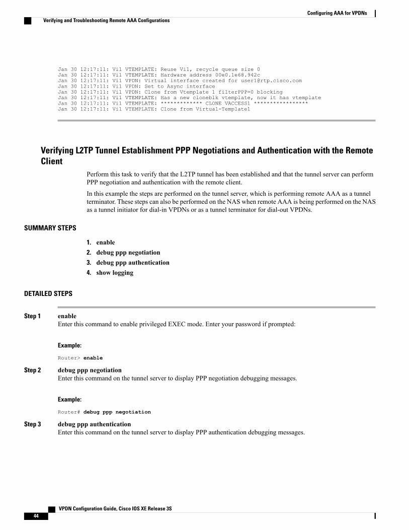
Jan 30 12:17:11: Vi1 VTEMPLATE: Reuse Vi1, recycle queue size 0Jan 30 12:17:11: Vi1 VTEMPLATE: Hardware address 00e0.1e68.942cJan 30 12:17:11: Vi1 VPDN: Virtual interface created for [email protected] 30 12:17:11: Vi1 VPDN: Set to Async interfaceJan 30 12:17:11: Vi1 VPDN: Clone from Vtemplate 1 filterPPP=0 blockingJan 30 12:17:11: Vi1 VTEMPLATE: Has a new cloneblk vtemplate, now it has vtemplateJan 30 12:17:11: Vi1 VTEMPLATE: ************* CLONE VACCESS1 *****************Jan 30 12:17:11: Vi1 VTEMPLATE: Clone from Virtual-Template1
Verifying L2TP Tunnel Establishment PPP Negotiations and Authentication with the RemoteClient
Perform this task to verify that the L2TP tunnel has been established and that the tunnel server can performPPP negotiation and authentication with the remote client.
In this example the steps are performed on the tunnel server, which is performing remote AAA as a tunnelterminator. These steps can also be performed on the NAS when remote AAA is being performed on the NASas a tunnel initiator for dial-in VPDNs or as a tunnel terminator for dial-out VPDNs.
SUMMARY STEPS
1. enable2. debug ppp negotiation3. debug ppp authentication4. show logging
DETAILED STEPS
Step 1 enableEnter this command to enable privileged EXEC mode. Enter your password if prompted:
Example:
Router> enable
Step 2 debug ppp negotiationEnter this command on the tunnel server to display PPP negotiation debugging messages.
Example:
Router# debug ppp negotiation
Step 3 debug ppp authenticationEnter this command on the tunnel server to display PPP authentication debugging messages.
VPDN Configuration Guide, Cisco IOS XE Release 3S44
Configuring AAA for VPDNsVerifying and Troubleshooting Remote AAA Configurations

Example:
Router# debug ppp authentication
Step 4 show loggingEnter this command on the tunnel server to display the contents of the standard system logging message buffer. Observethat the tunnel server receives a PPP Challenge Handshake Authentication Protocol (CHAP) challenge and then sendsa PPP CHAP "SUCCESS" to the client.
Example:
00:38:50: ppp3 PPP: Received LOGIN Response from AAA = PASS00:38:50: ppp3 PPP: Phase is FORWARDING, Attempting Forward00:38:50: Vi4.1 Tnl/Sn4571/4 L2TP: Session state change from wait-for-service-selection to established00:38:50: Vi4.1 PPP: Phase is AUTHENTICATING, Authenticated User00:38:50: Vi4.1 CHAP: O SUCCESS id 1 len 4
After PPP authentication is successful, observe from the debug output that PPP negotiation has started, that the tunnelserver has received Link Control Protocol (LCP) IP Control Protocol (IPCP) packets, and that negotiation is successful.
Example:
00:38:50: Vi4.1 IPCP: State is Open00:38:50: Vi4.1 IPCP: Install route to 10.1.1.4
Configuring Directed Request Authorization of VPDN UsersDirected request authorization of VPDN users can be configured on the NAS or on the tunnel server. Thedirected request configuration is performed on the device that ultimately performs the authentication. Directedrequests are most commonly configured on the tunnel server.
Perform one of these tasks to enable directed request authorization of VPDN users.
Configuring Directed Request Authorization of VPDN Users on the Tunnel ServerPerform this task on the tunnel server to configure directed request authorization of VPDN users when thetunnel server performs authentication.
VPDN Configuration Guide, Cisco IOS XE Release 3S 45
Configuring AAA for VPDNsConfiguring Directed Request Authorization of VPDN Users

Before You Begin
SUMMARY STEPS
1. enable2. configure terminal3. ip host {name | t modem-telephone-number} [tcp-port-number] address1 [address2...address8]4. Do one of the following:
• radius-server directed-request [restricted]
• tacacs-server directed-request [restricted] [no-truncate]
5. vpdn authorize directed-request
DETAILED STEPS
PurposeCommand or Action
Enables privileged EXEC mode.enableStep 1
Example:
Router> enable
• Enter your password if prompted.
Enters global configuration mode.configure terminal
Example:
Router# configure terminal
Step 2
Specifies or modifies the hostname for the network server.ip host {name | t modem-telephone-number}[tcp-port-number] address1 [address2...address8]
Step 3
The IP address specified with the ip host commandmust match the IP address you configured with theradius-server hostor tacacs-server host commandwhen performing the task in the Configuring RemoteAAA for VPDNs, on page 31.
Note
Example:
Router(config)# ip host example.com 10.3.3.3
Allows users logging in to a NAS to select a RADIUS serverfor authentication.
Do one of the following:Step 4
• radius-server directed-request [restricted]or
• tacacs-server directed-request [restricted][no-truncate] Allows users logging in to a NAS to select a TACACS+
server for authentication.
Example:
Router(config)# radius-server directed-request
VPDN Configuration Guide, Cisco IOS XE Release 3S46
Configuring AAA for VPDNsConfiguring Directed Request Authorization of VPDN Users
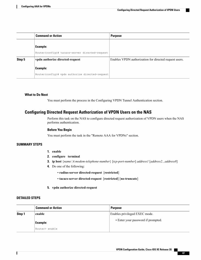
PurposeCommand or Action
Example:
Router(config)# tacacs-server directed-request
Enables VPDN authorization for directed request users.vpdn authorize directed-request
Example:
Router(config)# vpdn authorize directed-request
Step 5
What to Do Next
You must perform the process in the Configuring VPDN Tunnel Authentication section.
Configuring Directed Request Authorization of VPDN Users on the NASPerform this task on the NAS to configure directed request authorization of VPDN users when the NASperforms authentication.
Before You Begin
You must perform the task in the "Remote AAA for VPDNs" section.
SUMMARY STEPS
1. enable2. configure terminal3. ip host {name | t modem-telephone-number} [tcp-port-number] address1 [address2...address8]4. Do one of the following:
• radius-server directed-request [restricted]
• tacacs-server directed-request [restricted] [no-truncate]
5. vpdn authorize directed-request
DETAILED STEPS
PurposeCommand or Action
Enables privileged EXEC mode.enableStep 1
Example:
Router> enable
• Enter your password if prompted.
VPDN Configuration Guide, Cisco IOS XE Release 3S 47
Configuring AAA for VPDNsConfiguring Directed Request Authorization of VPDN Users

PurposeCommand or Action
Enters global configuration mode.configure terminal
Example:
Router# configure terminal
Step 2
Specifies or modifies the hostname for the network server.ip host {name | t modem-telephone-number}[tcp-port-number] address1 [address2...address8]
Step 3
The IP address specified with the ip host commandmust match the IP address you configured with theradius-server host or tacacs-server host commandwhen performing the task in the Configuring RemoteAAA for VPDNs, on page 31.
Note
Example:
Router(config)# ip host example.com 10.3.3.3
Allows users logging in to a NAS to select a RADIUS serverfor authentication.
Do one of the following:Step 4
• radius-server directed-request [restricted]or
• tacacs-server directed-request [restricted][no-truncate] Allows users logging in to a NAS to select a TACACS+ server
for authentication.
Example:
Router(config)# radius-server directed-request
Example:
Router(config)# tacacs-server directed-request
Enables VPDN authorization for directed request users.vpdn authorize directed-request
Example:
Router(config)# vpdn authorize directed-request
Step 5
What to Do Next
You must perform the process in the Configuring VPDN Tunnel Authentication section.
Configuring Domain Name Prefix and Suffix StrippingA single set of stripping rules can be configured globally. An independent set of stripping rules can beconfigured for each virtual private network (VPN) routing and forwarding (VRF) instance.
Global stripping rules are applied to all usernames, and per-VRF rules are applied only to usernames associatedwith the specified VRF. If a per-VRF rule is configured, it will take precedence over the global rule forusernames associated with that VRF.
VPDN Configuration Guide, Cisco IOS XE Release 3S48
Configuring AAA for VPDNsConfiguring Domain Name Prefix and Suffix Stripping

Perform this task on the NAS to configure a set of global or per-VRF stripping rules.
Before You Begin
• AAA must be enabled on the NAS. See the "Configuring AAA on the NAS and the Tunnel Server"section.
• Youmust understand the usage guidelines for the radius-server domain-stripping command as describedin the VPDN command reference.
SUMMARY STEPS
1. enable2. configure terminal3. Do one of the following:
• radius-server domain-stripping [right-to-left] [prefix-delimiter character[character2...character7]] [delimiter character [character2...character7]] [vrf vrf-name]
• tacacs-server domain-stripping [right-to-left] [prefix-delimiter character [character2...character7]][delimiter character [character2...character7]] [vrf vrf-name]
4. Do one of the following:
• radius-server domain-stripping strip-suffix suffix [vrf vrf-name]
• tacacs-server domain-stripping strip-suffix suffix [vrf vrf-name]
DETAILED STEPS
PurposeCommand or Action
Enables privileged EXEC mode.enableStep 1
Example:
Router> enable
• Enter your password if prompted.
Enters global configuration mode.configure terminal
Example:
Router# configure terminal
Step 2
(Optional) Configures a router to strip suffixes, or both suffixes and prefixes,from the username before forwarding the username to the RADIUS server.
Do one of the following:Step 3
• radius-server domain-stripping[right-to-left] [prefix-delimiter orcharacter [character2...character7]] (Optional) Configures a router to strip suffixes, or both suffixes and prefixes,
from the username before forwarding the username to the TACACS+ server.[delimiter character[character2...character7]] [vrfvrf-name]
VPDN Configuration Guide, Cisco IOS XE Release 3S 49
Configuring AAA for VPDNsConfiguring Domain Name Prefix and Suffix Stripping
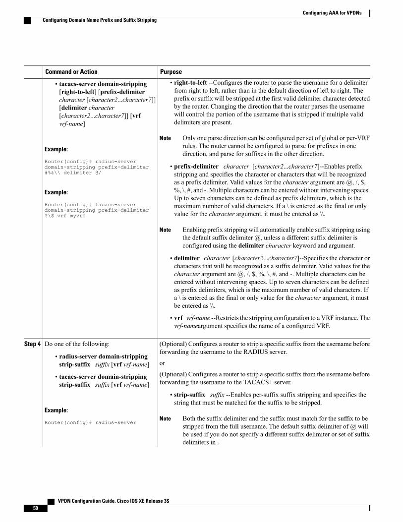
PurposeCommand or Action
• right-to-left --Configures the router to parse the username for a delimiterfrom right to left, rather than in the default direction of left to right. The
• tacacs-server domain-stripping[right-to-left] [prefix-delimiter
prefix or suffix will be stripped at the first valid delimiter character detectedcharacter [character2...character7]]by the router. Changing the direction that the router parses the username[delimiter characterwill control the portion of the username that is stripped if multiple validdelimiters are present.
[character2...character7]] [vrfvrf-name]
Only one parse direction can be configured per set of global or per-VRFrules. The router cannot be configured to parse for prefixes in onedirection, and parse for suffixes in the other direction.
Note
Example:
Router(config)# radius-server• prefix-delimiter character [character2...character7]--Enables prefixstripping and specifies the character or characters that will be recognized
domain-stripping prefix-delimiter#%&\\ delimiter @/
as a prefix delimiter. Valid values for the character argument are @, /, $,Example:
Router(config)# tacacs-server
%, \, #, and -. Multiple characters can be entered without intervening spaces.Up to seven characters can be defined as prefix delimiters, which is themaximum number of valid characters. If a \ is entered as the final or onlyvalue for the character argument, it must be entered as \\.domain-stripping prefix-delimiter
%\$ vrf myvrf
Enabling prefix stripping will automatically enable suffix stripping usingthe default suffix delimiter @, unless a different suffix delimiter isconfigured using the delimiter character keyword and argument.
Note
• delimiter character [character2...character7]--Specifies the character orcharacters that will be recognized as a suffix delimiter. Valid values for thecharacter argument are @, /, $, %, \, #, and -. Multiple characters can beentered without intervening spaces. Up to seven characters can be definedas prefix delimiters, which is the maximum number of valid characters. Ifa \ is entered as the final or only value for the character argument, it mustbe entered as \\.
• vrf vrf-name --Restricts the stripping configuration to a VRF instance. Thevrf-nameargument specifies the name of a configured VRF.
(Optional) Configures a router to strip a specific suffix from the username beforeforwarding the username to the RADIUS server.
Do one of the following:Step 4
• radius-server domain-strippingstrip-suffix suffix [vrf vrf-name] or
(Optional) Configures a router to strip a specific suffix from the username beforeforwarding the username to the TACACS+ server.
• tacacs-server domain-strippingstrip-suffix suffix [vrf vrf-name]
• strip-suffix suffix --Enables per-suffix suffix stripping and specifies thestring that must be matched for the suffix to be stripped.
Example:
Router(config)# radius-serverBoth the suffix delimiter and the suffix must match for the suffix to bestripped from the full username. The default suffix delimiter of @ willbe used if you do not specify a different suffix delimiter or set of suffixdelimiters in .
Note
VPDN Configuration Guide, Cisco IOS XE Release 3S50
Configuring AAA for VPDNsConfiguring Domain Name Prefix and Suffix Stripping

PurposeCommand or Action
• vrf vrf-name --Restricts the per-suffix stripping configuration to a VRFinstance. The vrf-nameargument specifies the name of a VRF.
domain-stripping strip-suffixcisco.com
Example:
Router(config)# tacacs-server
You can configure a single ruleset to strip multiple specific suffixes byperforming this step multiple times.
Note
domain-stripping strip-suffixcisco.net vrf myvrf
What to Do NextYou must perform the process in the Configuring VPDN Tunnel Authentication section.
Configuring VPDN Tunnel AuthenticationVPDN tunnel authentication enables routers to authenticate the other tunnel endpoint before establishing aVPDN tunnel. VPDN tunnel authentication is optional but highly recommended for L2TP, L2TPv3, and PPTPtunnels.
By default, the router will use the hostname as the tunnel name in VPDN tunnel authentication. If a localname is configured under a VPDN group, the router will use the local name when negotiating authenticationfor tunnels belonging to that VPDN group.
For NAS-initiated VPDN deployments VPDN deployments, tunnel authentication requires that a single sharedsecret be configured on both the NAS and the tunnel server. For L2TP tunnels, the password can be configuredusing the hostname, the local name, or the L2TP tunnel password.
For client-initiated VPDN tunneling deployments, tunnel authentication requires that a single shared secretbe configured on both the client and the tunnel server. The available authentication configuration optionsdepend on the tunneling protocol being used.
For L2TPv3 client-initiated VPDN tunnels, the shared secret can be configured on the local peer router andthe tunnel server in either of these ways:
• In an L2TP class configuration. Perform the task Configuring L2TP Control Channel AuthenticationParameters in the Configuring Client-Initiated Dial-In VPDN Tunneling module instead of the processdocumented in this section.
• Using the hostname of the router as described in the process documented in this section.
For L2TP client-initiated VPDN tunnels, the shared secret can be configured on the tunnel server using thehostname, the local name, or the L2TP tunnel password as described the process documented in this section.The shared secret can be configured on the local peer router in either of these ways:
• In an L2TP class configuration. Perform the task Configuring L2TP Control Channel AuthenticationParameters in the Configuring Client-Initiated Dial-In VPDN Tunneling module instead of the processdocumented in this section.
• Using the hostname of the router as described in the process documented in this section.
VPDN Configuration Guide, Cisco IOS XE Release 3S 51
Configuring AAA for VPDNsConfiguring VPDN Tunnel Authentication

For PPTP client-initiated VPDN tunnels, authentication parameters can be configured by using the hostnameor the local name as described in the process documented in this section.
To configure VPDN tunnel authentication, you must perform one of the following tasks on the NAS and thetunnel server as required. You need not choose the same method to configure the secret on the NAS and thetunnel server. However, the configured password must be the same on both devices.
VPDN tunnel authentication is optional for L2TP tunnels. Perform this task on the NAS and the tunnel serverif you want to disable VPDN tunnel authentication:
PrerequisitesAAA must be enabled. See the Configuring AAA on the NAS and the Tunnel Server section.
Configuring VPDN Tunnel Authentication Using the HostnamePerform this task on the NAS or tunnel server to configure VPDN tunnel authentication using the hostname.
SUMMARY STEPS
1. enable2. configure terminal3. hostname name4. username name password secret
DETAILED STEPS
PurposeCommand or Action
Enables privileged EXEC mode.enableStep 1
Example:
Router> enable
• Enter your password if prompted.
Enters global configuration mode.configure terminal
Example:
Router# configure terminal
Step 2
Specifies or modifies the hostname for the network server.hostname name
Example:
Router(config)# hostname tunnelserver12
Step 3
Establishes a username-based authentication system.username name password secretStep 4
VPDN Configuration Guide, Cisco IOS XE Release 3S52
Configuring AAA for VPDNsConfiguring VPDN Tunnel Authentication

PurposeCommand or Action
Example:
Router(config)# username nas4 passwordmysecret
• The specified username must be the name of the remoterouter.
• The secret password must be the same on both routers.
What to Do Next
• Once you have configured a secret password on one tunnel endpoint, you must configure the same tunnelsecret on the corresponding tunnel endpoint.
Configuring VPDN Tunnel Authentication Using the Local NamePerform this task on the NAS or tunnel server to configure VPDN tunnel authentication using the local name.
SUMMARY STEPS
1. enable2. configure terminal3. vpdn-group name4. local name host-name5. exit6. username name password secret
DETAILED STEPS
PurposeCommand or Action
Enables privileged EXEC mode.enableStep 1
Example:
Router> enable
• Enter your password if prompted.
Enters global configuration mode.configure terminal
Example:
Router# configure terminal
Step 2
VPDN Configuration Guide, Cisco IOS XE Release 3S 53
Configuring AAA for VPDNsConfiguring VPDN Tunnel Authentication

PurposeCommand or Action
Enters VPDN group configurationmode and creates a VPDNgroup.
vpdn-group name
Example:
Router(config)# vpdn-group mygroup
Step 3
Specifies a local hostname that the tunnel will use to identifyitself.
local name host-name
Example:
Router(config-vpdn)# local name tunnelserver2
Step 4
Exits VPDN group configuration mode.exit
Example:
Router(config-vpdn)# exit
Step 5
Establishes a username-based authentication system.username name password secretStep 6
Example:
Router(config)# username nas7 passwordmysecret
• The specified usernamemust be the name of the remoterouter.
• The secret password must be the same on both routers.
What to Do Next
• Once you have configured a secret password on one tunnel endpoint, you must configure the same tunnelsecret on the corresponding tunnel endpoint.
Configuring VPDN Tunnel Authentication Using the L2TP Tunnel PasswordPerform this task on the NAS or tunnel server to configure VPDN tunnel authentication using the L2TP tunnelpassword. This task can be used only for VPDN tunnel authentication of L2TP tunnels.
SUMMARY STEPS
1. enable2. configure terminal3. vpdn-group name4. l2tp tunnel password password5. local name host-name6. exit7. username name password secret
VPDN Configuration Guide, Cisco IOS XE Release 3S54
Configuring AAA for VPDNsConfiguring VPDN Tunnel Authentication

DETAILED STEPS
PurposeCommand or Action
Enables privileged EXEC mode.enableStep 1
Example:
Router> enable
• Enter your password if prompted.
Enters global configuration mode.configure terminal
Example:
Router# configure terminal
Step 2
Enters VPDN group configuration mode and creates a VPDN group.vpdn-group name
Example:
Router(config)# vpdn-group mygroup
Step 3
Sets the password that the router will use to authenticate the tunnel.l2tp tunnel password password
Example:
Router(config-vpdn)# l2tp tunnel passwordmysecret
Step 4
(Optional) Specifies a local hostname that the tunnel will use toidentify itself.
local name host-name
Example:
Router(config-vpdn)# local nametunnelserver2
Step 5
• You must perform this step if the remote router does not usethe L2TP tunnel password.
(Optional) Exits VPDN group configuration mode.exitStep 6
Example:
Router(config-vpdn)# exit
• You must perform this step only if the remote router does notuse the L2TP tunnel password method of VPDN tunnelauthentication.
(Optional) Establishes a username-based authentication system.username name password secretStep 7
Example:
Router(config)# username nas64 passwordmysecret
• You need to perform this step only if the remote router doesnot use the L2TP tunnel password method of VPDN tunnelauthentication.
• The specified username must be the name of the remote router.
• The password must be the same on both routers.
VPDN Configuration Guide, Cisco IOS XE Release 3S 55
Configuring AAA for VPDNsConfiguring VPDN Tunnel Authentication

What to Do Next
• Once you have configured a secret password on one tunnel endpoint, you must configure the same tunnelsecret on the corresponding tunnel endpoint.
Disabling VPDN Tunnel Authentication for L2TP TunnelsPerform this task to disable VPDN tunnel authentication for L2TP tunnels. You must perform this task onboth the NAS and the tunnel server to disable VPDN tunnel authentication.
SUMMARY STEPS
1. enable2. configure terminal3. vpdn-group name4. no l2tp tunnel authentication
DETAILED STEPS
PurposeCommand or Action
Enables privileged EXEC mode.enableStep 1
Example:
Router> enable
• Enter your password if prompted.
Enters global configuration mode.configure terminal
Example:
Router# configure terminal
Step 2
Enters VPDN group configuration mode and creates aVPDN group.
vpdn-group name
Example:
Router(config)# vpdn-group mygroup
Step 3
Disables L2TP tunnel authentication.no l2tp tunnel authentication
Example:
Router(config-vpdn)# no l2tp tunnelauthentication
Step 4
VPDN Configuration Guide, Cisco IOS XE Release 3S56
Configuring AAA for VPDNsConfiguring VPDN Tunnel Authentication

Configuring RADIUS Tunnel Accounting for L2TP VPDNsThe new RADIUS tunnel accounting types are used with the RADIUS accounting attribute Acct-Status-Type(attribute 40), which indicates whether an accounting request marks the beginning of user service (start) orthe end (stop).
Perform this task to configure a NAS or tunnel server to send tunnel and tunnel-link accounting records tothe remote RADIUS server.
Before You Begin
• You must perform the tasks in the Configuring AAA on the NAS and the Tunnel Server, on page 30.
• You must configure the router to use a remote RADIUS AAA server as described in the ConfiguringRemote AAA for VPDNs, on page 31.
• You must perform the tasks in the "Configuring VPDN Tunnel Authentication" section.
RADIUS tunnel accounting is supported only for VPDNs using the L2TP protocol.Note
SUMMARY STEPS
1. enable2. configure terminal3. aaa accounting network default | list-name} {start-stop | stop-only |wait-start | none group groupname4. vpdn tunnel accounting network list-name5. vpdn session accounting network list-name
DETAILED STEPS
PurposeCommand or Action
Enables privileged EXEC mode.enableStep 1
Example:
Router> enable
• Enter your password if prompted.
Enters global configuration mode.configure terminal
Example:
Router# configure terminal
Step 2
Enables network accounting.aaa accounting network default | list-name}{start-stop | stop-only | wait-start | nonegroup groupname
Step 3
• default --If the default network accountingmethod-list is configuredand no additional accounting configurations are enabled on the
VPDN Configuration Guide, Cisco IOS XE Release 3S 57
Configuring AAA for VPDNsConfiguring RADIUS Tunnel Accounting for L2TP VPDNs
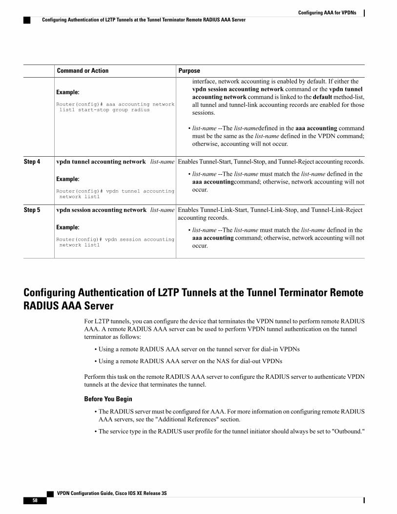
PurposeCommand or Action
Example:
Router(config)# aaa accounting networklist1 start-stop group radius
interface, network accounting is enabled by default. If either thevpdn session accounting network command or the vpdn tunnelaccounting network command is linked to the defaultmethod-list,all tunnel and tunnel-link accounting records are enabled for thosesessions.
• list-name --The list-namedefined in the aaa accounting commandmust be the same as the list-name defined in the VPDN command;otherwise, accounting will not occur.
Enables Tunnel-Start, Tunnel-Stop, and Tunnel-Reject accounting records.vpdn tunnel accounting network list-nameStep 4
Example:
Router(config)# vpdn tunnel accountingnetwork list1
• list-name --The list-name must match the list-name defined in theaaa accountingcommand; otherwise, network accounting will notoccur.
Enables Tunnel-Link-Start, Tunnel-Link-Stop, and Tunnel-Link-Rejectaccounting records.
vpdn session accounting network list-name
Example:
Router(config)# vpdn session accountingnetwork list1
Step 5
• list-name --The list-name must match the list-name defined in theaaa accounting command; otherwise, network accounting will notoccur.
Configuring Authentication of L2TP Tunnels at the Tunnel Terminator RemoteRADIUS AAA Server
For L2TP tunnels, you can configure the device that terminates the VPDN tunnel to perform remote RADIUSAAA. A remote RADIUS AAA server can be used to perform VPDN tunnel authentication on the tunnelterminator as follows:
• Using a remote RADIUS AAA server on the tunnel server for dial-in VPDNs
• Using a remote RADIUS AAA server on the NAS for dial-out VPDNs
Perform this task on the remote RADIUS AAA server to configure the RADIUS server to authenticate VPDNtunnels at the device that terminates the tunnel.
Before You Begin
• The RADIUS server must be configured for AAA. For more information on configuring remote RADIUSAAA servers, see the "Additional References" section.
• The service type in the RADIUS user profile for the tunnel initiator should always be set to "Outbound."
VPDN Configuration Guide, Cisco IOS XE Release 3S58
Configuring AAA for VPDNsConfiguring Authentication of L2TP Tunnels at the Tunnel Terminator Remote RADIUS AAA Server

This task applies only when the device that terminates the VPDN tunnel is performing remote RADIUSAAA. To configure the tunnel terminator to perform remote RADIUS AAA, perform the task in the"Configuring the Tunnel Terminator for Remote RADIUS AAA for L2TP Tunnels" section.
Note
SUMMARY STEPS
1. service type = Outbound2. tunnel-type = protocol3. Cisco:Cisco-Avpair = vpdn:dout-dialer = NAS-dialer-number4. Cisco:Cisco-Avpair = vpdn:vpdn-vtemplate = vtemplate-number
DETAILED STEPS
PurposeCommand or Action
Specifies the service type.service type = Outbound
Example:
service type = Outbound
Step 1
Specifies the tunneling protocol.tunnel-type = protocolStep 2
Example:
tunnel-type = l2tp
L2TP is the only valid protocol for thistask.
Note
Specifies which dialer to use on the NAS for dial-out configuration.Cisco:Cisco-Avpair = vpdn:dout-dialer =NAS-dialer-number
Step 3
Perform this step only for dial-outconfigurations.
Note
Example:
Cisco:Cisco-Avpair = vpdn:dout-dialer = 2
Specifies the virtual template number to use on the tunnel serverfor dial-in configuration.
Cisco:Cisco-Avpair = vpdn:vpdn-vtemplate =vtemplate-number
Step 4
Example:
Cisco:Cisco-Avpair = vpdn:vpdn-vtemplate =1
Perform this step only for dial-inconfigurations.
Note
This configuration is optional if the vpdn tunnelauthorization virtual-template command is used in thetask in the Configuring the Tunnel Terminator for RemoteRADIUS AAA for L2TP Tunnels, on page 34.
Note
VPDN Configuration Guide, Cisco IOS XE Release 3S 59
Configuring AAA for VPDNsConfiguring Authentication of L2TP Tunnels at the Tunnel Terminator Remote RADIUS AAA Server

Configuring Tunnel Assignments on the NAS Remote RADIUS AAA ServerTunnel assignments allow the grouping of users from different per-user or domain RADIUS profiles into thesame active tunnel. This functionality prevents the establishment of duplicate tunnels when the tunnel type,tunnel endpoints, and tunnel assignment ID are identical.
Perform this task on the NAS remote RADIUS AAA server for each user and domain that you want to groupinto the same tunnel.
Before You Begin
The RADIUS server must be configured for AAA.
SUMMARY STEPS
1. Do one of the following:
• user @ domain.com Password = " secret " Service-Type = Outbound
• user.domain.com Password = " secret " Service-Type = Outbound
2. tunnel-type = protocol3. tunnel-server-endpoint = ip-address4. tunnel-assignment-id = name
DETAILED STEPS
PurposeCommand or Action
Specifies the user or domain, the tunnel password, and theservice type.
Do one of the following:Step 1
• user @ domain.com Password = " secret "Service-Type = Outbound
• user.domain.com Password = " secret "Service-Type = Outbound
Example:
[email protected] Password = "cisco" Service-Type= Outbound
Example:
user.cisco.com Password = "cisco" Service-Type= Outbound
Specifies the tunneling protocol used.tunnel-type = protocolStep 2
Example:
tunnel-type = l2tp
• The tunnel type must be identical for users to begrouped into the same tunnel.
VPDN Configuration Guide, Cisco IOS XE Release 3S60
Configuring AAA for VPDNsConfiguring Tunnel Assignments on the NAS Remote RADIUS AAA Server

PurposeCommand or Action
Specifies the IP address of the tunnel server that calls fromthe specified user or domain are tunneled to.
tunnel-server-endpoint = ip-address
Example:
tunnel-server-endpoint = 10.1.1.1
Step 3
• The tunnel server endpoint must be identical for usersto be grouped into the same tunnel.
Specifies the tunnel ID that calls from the specified user ordomain are assigned.
tunnel-assignment-id = name
Example:
tunnel-assignment-id = group1
Step 4
• The tunnel assignment ID must be identical for usersto be grouped into the same tunnel.
Configuring Secure Tunnel Authentication Names on the NAS Remote RADIUSAAA Server
The NAS AAA server can be configured with authentication names other than the default names for the NASand the NAS AAA server, providing a higher level of security during VPDN tunnel establishment.
RADIUS tunnel authentication name attributes allows you to specify a name other than the default name forthe tunnel initiator and for the tunnel terminator. These authentication names are specified using RADIUStunnel attributes 90 and 91.
Perform this task on the remote RADIUS AAA server. This task applies to NAS-initiated tunnels using eitherL2TP or L2F.
Before You Begin
• The RADIUS server must be configured for AAA.
• The NAS must be able to recognize RADIUS attributes 90 and 91.
• The RADIUS server must support tagged attributes to use RADIUS tunnel attributes 90 and 91. Taggedattributes are defined in RFC 2868, RADIUS Tunnel Authentication Attributes .
SUMMARY STEPS
1. Do one of the following:
• user @ example.com Password = " secret " Service-Type = Outbound
• user.example.com Password = " secret " Service-Type = Outbound
2. tunnel-client-auth-id = {:1 | :2}: " NAS-name "3. tunnel-server-auth-id = {:1 | :2}: " tunnel-server-name "
VPDN Configuration Guide, Cisco IOS XE Release 3S 61
Configuring AAA for VPDNsConfiguring Secure Tunnel Authentication Names on the NAS Remote RADIUS AAA Server
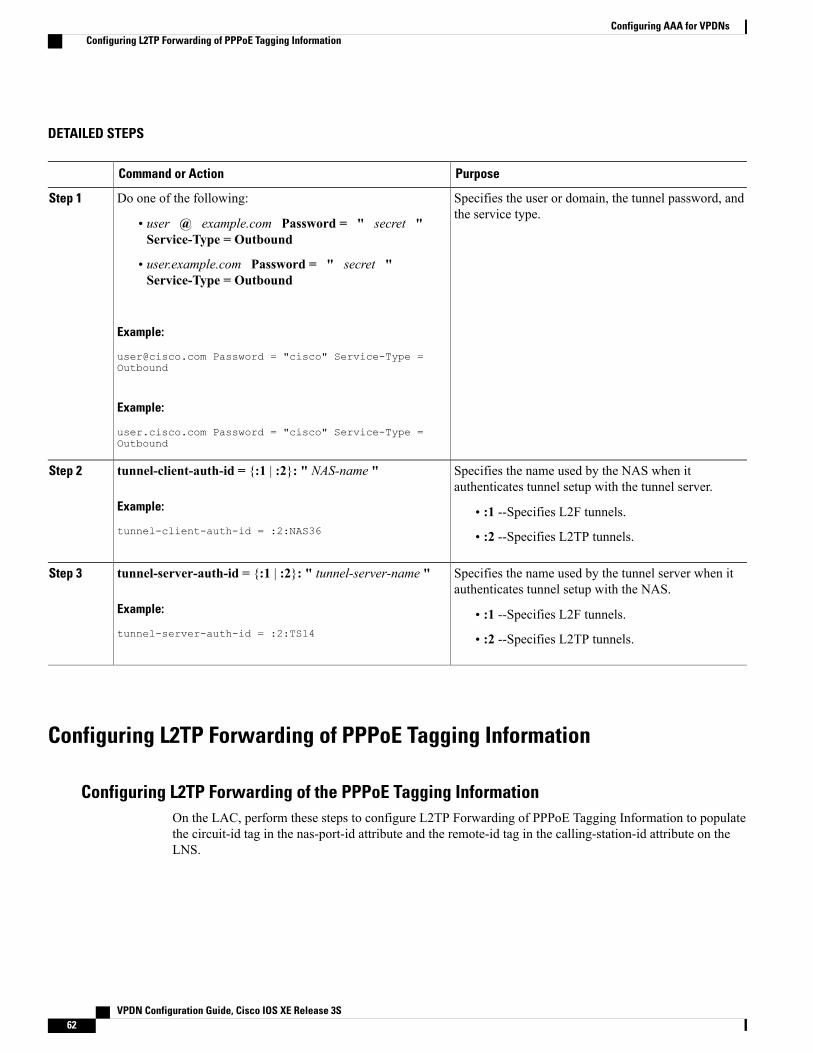
DETAILED STEPS
PurposeCommand or Action
Specifies the user or domain, the tunnel password, andthe service type.
Do one of the following:Step 1
• user @ example.com Password = " secret "Service-Type = Outbound
• user.example.com Password = " secret "Service-Type = Outbound
Example:
[email protected] Password = "cisco" Service-Type =Outbound
Example:
user.cisco.com Password = "cisco" Service-Type =Outbound
Specifies the name used by the NAS when itauthenticates tunnel setup with the tunnel server.
tunnel-client-auth-id = {:1 | :2}: " NAS-name "
Example:
tunnel-client-auth-id = :2:NAS36
Step 2
• :1 --Specifies L2F tunnels.
• :2 --Specifies L2TP tunnels.
Specifies the name used by the tunnel server when itauthenticates tunnel setup with the NAS.
tunnel-server-auth-id = {:1 | :2}: " tunnel-server-name "
Example:
tunnel-server-auth-id = :2:TS14
Step 3
• :1 --Specifies L2F tunnels.
• :2 --Specifies L2TP tunnels.
Configuring L2TP Forwarding of PPPoE Tagging Information
Configuring L2TP Forwarding of the PPPoE Tagging InformationOn the LAC, perform these steps to configure L2TP Forwarding of PPPoE Tagging Information to populatethe circuit-id tag in the nas-port-id attribute and the remote-id tag in the calling-station-id attribute on theLNS.
VPDN Configuration Guide, Cisco IOS XE Release 3S62
Configuring AAA for VPDNsConfiguring L2TP Forwarding of PPPoE Tagging Information

SUMMARY STEPS
1. enable2. configure terminal3. vpdn-group name4. dsl-line-info-forwarding5. exit
DETAILED STEPS
PurposeCommand or Action
Enables privileged EXEC mode.enableStep 1
Example:
Router> enable
• Enter your password if prompted.
Enters global configuration mode.configure terminal
Example:
Router# configure terminal
Step 2
Creates a VPDN group and enters VPDN group configurationmode.
vpdn-group name
Example:
Router(config)# vpdn-group pppoe-group
Step 3
Enables the processing of the received PPPoEVendor-Specifictag in the PADR packet, and sends a matching VSA to theAAA server in RADIUS access and accounting requests.
dsl-line-info-forwarding
Example:
Router(config-vpdn)#dsl-line-info-forwarding
Step 4
Exits VPDN group configuration mode.exit
Example:
Router(config-vpdn)# exit
Step 5
Overriding L2TP Forwarding of PPPoE Tag InformationYou can configure the L2TP Forwarding of PPPoE Tagging Information feature to override the followingVSA:
VPDN Configuration Guide, Cisco IOS XE Release 3S 63
Configuring AAA for VPDNsConfiguring L2TP Forwarding of PPPoE Tagging Information

Overriding nas-port VSA with circuit-id
To override the population of the circuit-id tag in the nas-port-id attribute on the LNS, perform these stepson the LNS.
SUMMARY STEPS
1. enable2. configure terminal3. radius-server attribute 87 circuit-id4. exit
DETAILED STEPS
PurposeCommand or Action
Enables privileged EXEC mode.enableStep 1
Example:
Router> enable
• Enter your password if prompted.
Enters global configuration mode.configure terminal
Example:
Router# configure terminal
Step 2
Overrides the NAS-Port-Id attribute with the Circuit-IDattribute in RADIUS access and accounting requests.
radius-server attribute 87 circuit-id
Example:
Router(config)# radius-server attribute 87circuit-id
Step 3
Exits the current mode.exit
Example:
Router(config)# exit
Step 4
Overriding calling-station-id VSA with remote-id
To override the calling-station-id VSA with the remote-id on the LNS, perform these steps:
VPDN Configuration Guide, Cisco IOS XE Release 3S64
Configuring AAA for VPDNsConfiguring L2TP Forwarding of PPPoE Tagging Information

SUMMARY STEPS
1. enable2. configure terminal3. radius-server attribute 31 remote-id4. exit
DETAILED STEPS
PurposeCommand or Action
Enables privileged EXEC mode.enableStep 1
Example:
Router> enable
• Enter your password if prompted.
Enters global configuration mode.configure terminal
Example:
Router # configure terminal
Step 2
Overrides the calling-station-id attribute with Remote-IDattribute in RADIUS access and accounting requests.
radius-server attribute 31 remote-id
Example:
Router(config)# radius-server attribute 31remote-id
Step 3
Exits the current mode.exit
Example:
Router(config)# exit
Step 4
Removing L2TP Forwarding of PPPoE Tag InformationOutgoing PADO and PADS packets will have the DSLAM-inserted Vendor-Specific Line-Id tag, andDSLAMmust strip the Circuit-Id tag from the packets. If the DSLAM cannot strip the tag, the BRAS must remove itbefore sending out the packets. This task is accomplished through configuration of the vendor-tag remote-idstrip command under BBA group configuration mode.
VPDN Configuration Guide, Cisco IOS XE Release 3S 65
Configuring AAA for VPDNsConfiguring L2TP Forwarding of PPPoE Tagging Information
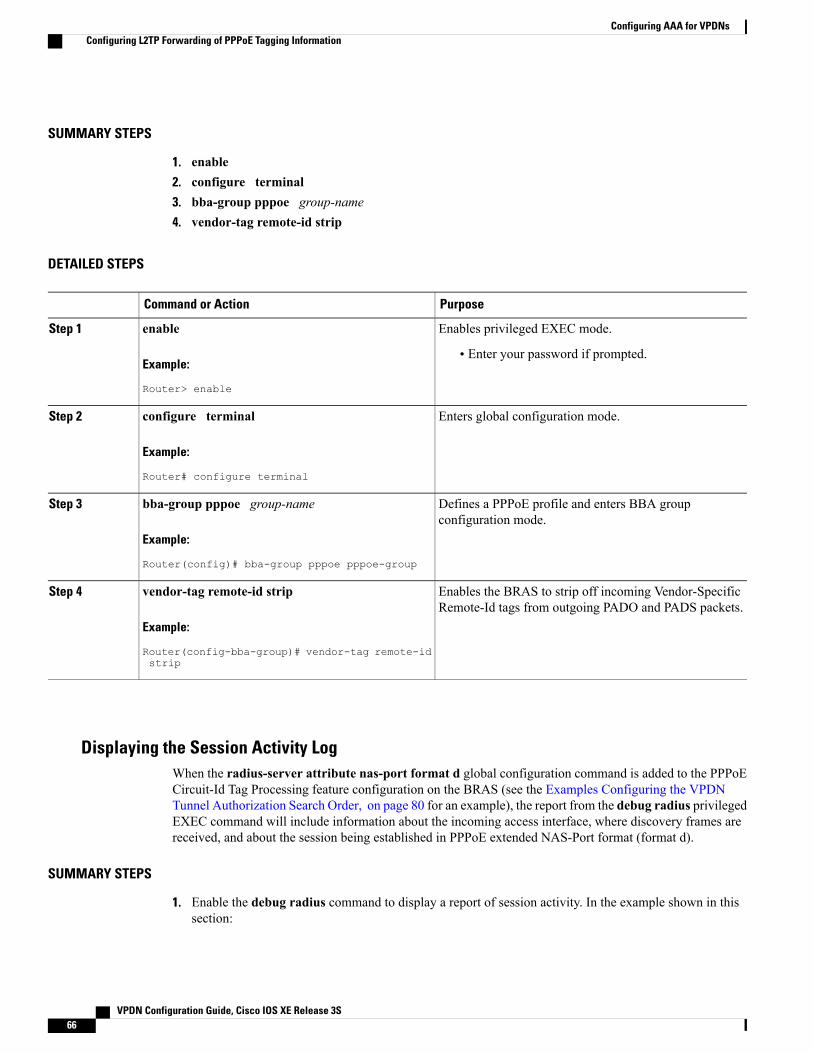
SUMMARY STEPS
1. enable2. configure terminal3. bba-group pppoe group-name4. vendor-tag remote-id strip
DETAILED STEPS
PurposeCommand or Action
Enables privileged EXEC mode.enableStep 1
Example:
Router> enable
• Enter your password if prompted.
Enters global configuration mode.configure terminal
Example:
Router# configure terminal
Step 2
Defines a PPPoE profile and enters BBA groupconfiguration mode.
bba-group pppoe group-name
Example:
Router(config)# bba-group pppoe pppoe-group
Step 3
Enables the BRAS to strip off incoming Vendor-SpecificRemote-Id tags from outgoing PADO and PADS packets.
vendor-tag remote-id strip
Example:
Router(config-bba-group)# vendor-tag remote-idstrip
Step 4
Displaying the Session Activity LogWhen the radius-server attribute nas-port format d global configuration command is added to the PPPoECircuit-Id Tag Processing feature configuration on the BRAS (see the Examples Configuring the VPDNTunnel Authorization Search Order, on page 80 for an example), the report from the debug radius privilegedEXEC command will include information about the incoming access interface, where discovery frames arereceived, and about the session being established in PPPoE extended NAS-Port format (format d).
SUMMARY STEPS
1. Enable the debug radius command to display a report of session activity. In the example shown in thissection:
VPDN Configuration Guide, Cisco IOS XE Release 3S66
Configuring AAA for VPDNsConfiguring L2TP Forwarding of PPPoE Tagging Information

DETAILED STEPS
Enable the debug radius command to display a report of session activity. In the example shown in this section:
• The acct_session_id is 79 or 4F in hexadecimal format.
• In the message Acct-session-id pre-pended with Nas Port = 0/0/0/200, the interface on which the PPPoE discoveryframes arrived is FastEthernet0/0.200. The 0/0/0 is Cisco format for slot/subslot/port.
• The Acct-Session-Id vendor-specific attribute 44 contains the string 0/0/0/200_0000004F, which is a combinationof the ingress interface and the session identifier.
Strings of interest in the debug radius output log are presented in bold text for purpose of example only.Note
Example:
Router# debug radius02:10:49: RADIUS(0000003F): Config NAS IP: 0.0.0.002:10:49: RADIUS/ENCODE(0000003F): acct_session_id: 7902:10:49: RADIUS(0000003F): sending02:10:49: RADIUS/ENCODE: Best Local IP-Address 10.0.58.141 for Radius-Server 172.20.164.14302:10:49: RADIUS(0000003F): Send Access-Request to 172.20.164.143:1645 id 1645/65, len 9802:10:49: RADIUS: authenticator 1C 9E B0 A2 82 51 C1 79 - FE 24 F4 D1 2F 84 F5 7902:10:49: RADIUS: Framed-Protocol [7] 6 PPP [1]02:10:49: RADIUS: User-Name [1] 7 "peer1"02:10:49: RADIUS: CHAP-Password [3] 19 *02:10:49: RADIUS: NAS-Port-Type [61] 6 Ethernet [15]02:10:49: RADIUS: NAS-Port [5] 6 20002:10:49: RADIUS: NAS-Port-Id [87] 22 "FastEthernet6/0.200:"02:10:49: RADIUS: Service-Type [6] 6 Framed [2]02:10:49: RADIUS: NAS-IP-Address [4] 6 10.0.58.14102:10:49: RADIUS: Received from id 1645/65 172.20.164.143:1645, Access-Accept, len 32 02:10:49:RADIUS: authenticator 06 45 84 1B 27 1F A5 C3 - C3 C9 69 6E B9 C0 6F 9402:10:49: RADIUS: Service-Type [6] 6 Framed [2]02:10:49: RADIUS: Framed-Protocol [7] 6 PPP [1]02:10:49: RADIUS(0000003F): Received from id 1645/6502:10:49: [62]PPPoE 65: State LCP_NEGOTIATION Event PPP_LOCAL02:10:49: PPPoE 65/SB: Sent vtemplate request on base Vi202:10:49: [62]PPPoE 65: State VACCESS_REQUESTED Event VA_RESP02:10:49: [62]PPPoE 65: Vi2.1 interface obtained02:10:49: [62]PPPoE 65: State PTA_BINDING Event STAT_BIND02:10:49: [62]PPPoE 65: data path set to Virtual Acess02:10:49: [62]PPPoE 65: Connected PTA02:10:49: [62]PPPoE 65: AAA get dynamic attrs02:10:49: [62]PPPoE 65: AAA get dynamic attrs02:10:49: RADIUS/ENCODE(0000003F):Orig. component type = PPoE02:10:49: RADIUS/ENCODE(0000003F): Acct-session-id pre-pended with Nas Port = 0/0/0/20002:10:49: RADIUS(0000003F): Config NAS IP: 0.0.0.002:10:49: RADIUS(0000003F): sending02:10:49: RADIUS/ENCODE: Best Local IP-Address 10.0.58.141 for Radius-Server 172.20.164.14302:10:49: RADIUS(0000003F): Send Accounting-Request to 172.20.164.143:1646 id 1 646/42, len 11702:10:49: RADIUS: authenticator 57 24 38 1A A3 09 62 42 - 55 2F 41 71 38 E1 CC 2402:10:49: RADIUS: Acct-Session-Id [44] 20 "0/0/0/200_0000004F"02:10:49: RADIUS: Framed-Protocol [7] 6 PPP [1]02:10:49: RADIUS: User-Name [1] 7 "peer1"02:10:49: RADIUS: Acct-Authentic [45] 6 RADIUS [1]02:10:49: RADIUS: Acct-Status-Type [40] 6 Start [1]02:10:49: RADIUS: NAS-Port-Type [61] 6 Ethernet [15]02:10:49: RADIUS: NAS-Port [5] 6 20002:10:49: RADIUS: NAS-Port-Id [87] 22 "FastEthernet6/0.200:"02:10:49: RADIUS: Service-Type [6] 6 Framed [2]02:10:49: RADIUS: NAS-IP-Address [4] 6 10.0.58.14102:10:49: RADIUS: Acct-Delay-Time [41] 6 0
VPDN Configuration Guide, Cisco IOS XE Release 3S 67
Configuring AAA for VPDNsConfiguring L2TP Forwarding of PPPoE Tagging Information

02:10:49: RADIUS: Received from id 1646/42 172.20.164.143:1646, Accounting-resp onse, len 2002:10:49: RADIUS: authenticator 34 84 7E B2 F4 40 B2 7C - C5 B2 4E 98 78 03 8B C0
Configuring L2TP Override Forwarding rx-speed and tx-speed Values Receivedfrom PPPoE
By default, L2TP obtains the receive-speed (rx-speed) and transmit-speed (tx-speed) values from PPPoE andsends the values to LNS. To override L2TP forwarding of the rx-speed and tx-speed values received fromPPPoE, the rx-speed and the tx-speed values should be configured in the RADIUS server, or by using the l2tprx-speed and l2tp tx-speed commands in VPDN group configuration or VPDN template configuration mode.The speed values are configured in kbps.
Configuring rx-speed and tx-speed Values When the RADIUS Server Is Not UsedWhen the RADIUS server is not used, the rx-speed and the tx-speed values can be configured in VPDN groupconfiguration or VPDN template configuration mode. The rx-speed and tx-speed values configured in VPDNgroup configuration mode are specific to the tunnel and are sent to all sessions under the tunnel.
Perform this task to configure rx-speed and tx-speed values in VPDN group configuration or VPDN templateconfiguration mode when the RADIUS server is not used.
SUMMARY STEPS
1. enable2. configure terminal3. vpdn enable4. Do one of the following:
• vpdn-group name
• vpdn-template name
5. l2tp rx-speed value6. l2tp tx-speed value7. end
DETAILED STEPS
PurposeCommand or Action
Enables privileged EXEC mode.enableStep 1
Example:
Router> enable
• Enter your password if prompted.
VPDN Configuration Guide, Cisco IOS XE Release 3S68
Configuring AAA for VPDNsConfiguring L2TP Override Forwarding rx-speed and tx-speed Values Received from PPPoE

PurposeCommand or Action
Enters global configuration mode.configure terminal
Example:
Router# configure terminal
Step 2
Enables VPDN on the router.vpdn enable
Example:
Router(config)# vpdn enable
Step 3
Enters VPDN group configuration mode.Do one of the following:Step 4
or• vpdn-group nameEnters VPDN template configuration mode.• vpdn-template name
Example:
Router(config)# vpdn-group 1
Example:
Router(config)# vpdn-template 1
Sends the rx-speed value to LNS.l2tp rx-speed valueStep 5
Example:
Router(config-vpdn)# l2tp rx-speed 15000
• If the rx-speed value is not provided, L2TP receives therx-speed value from PPPoE.
The command is the same irrespective of whether it isentered from VPDN group configuration or VPDNtemplate configuration mode. These steps show how toenter the command from VPDN group configurationmode.
Note
Sends the tx-speed value to LNS.l2tp tx-speed valueStep 6
Example:
Router(config-vpdn)# l2tp tx-speed 15000
• If the tx-speed value is not provided, L2TP receives thetx-speed value from PPPoE.
Exits VPDN group configuration mode and returns to privilegedEXEC mode.
end
Example:
Router(config-vpdn)# end
Step 7
VPDN Configuration Guide, Cisco IOS XE Release 3S 69
Configuring AAA for VPDNsConfiguring L2TP Override Forwarding rx-speed and tx-speed Values Received from PPPoE

Configuring rx-speed and tx-speed Values on the RADIUS ServerYou can configure the rx-speed and tx-speed values on the RADIUS server by Specifying the rx-speed andtx-speed values on the RADIUS server.
The values configured for rx-speed and tx-speed are session oriented. L2TP stores the rx-speed and tx-speedvalues for every session by using the vpdn-authen-before-forward command configured on LAC.
The steps for configuring the default rx-speed and tx-speed values on the RADIUS server are the same asconfiguring the rx-speed and tx-speed values when the RADIUS server is not used. For configuring rx-speedand tx-speed values on the RADIUS server, see the Configuring rx-speed and tx-speed Values When theRADIUS Server Is Not Used section.
Configuring rx-speed and tx-speed Values from ANCP on the RADIUS ServerANCP sends the upstream and downstream values to L2TP. The upstream value is the rx-speed value and thedownstream value is the tx-speed value.
Perform this task on the RADIUS server to configure rx-speed and tx-speed values from ANCP.
Before You Begin
• The quality of service (QoS) policy must be attached to PPPoE between the client and the LAC.
• The ANCP session and the ANCP neighbor session must be started.
• The average rate traffic shaping value must be configured for the default class by using the shape averagecommand in policy-map class configuration mode.
SUMMARY STEPS
1. enable2. configure terminal3. vpdn enable4. Do one of the following:
• vpdn-group name
• vpdn-template name
5. l2tp rx-speed ancp [value]6. l2tp tx-speed ancp [value]7. end
DETAILED STEPS
PurposeCommand or Action
Enables privileged EXEC mode.enableStep 1
VPDN Configuration Guide, Cisco IOS XE Release 3S70
Configuring AAA for VPDNsConfiguring L2TP Override Forwarding rx-speed and tx-speed Values Received from PPPoE

PurposeCommand or Action
Example:
Router> enable
• Enter your password if prompted.
Enters global configuration mode.configure terminal
Example:
Router# configure terminal
Step 2
Enables VPDN on the router.vpdn enable
Example:
Router(config)# vpdn enable
Step 3
Enters VPDN group configuration mode.Do one of the following:Step 4
or• vpdn-group nameEnters VPDN template configuration mode.• vpdn-template name
Example:
Router(config)# vpdn-group 1
Example:
Router(config)# vpdn-template 1
Sends the rx-speed value to LNS if a value is not configured for ANCP.l2tp rx-speed ancp [value]Step 5
Example:
Router(config-vpdn)# l2tprx-speed ancp 15000
• If the rx-speed value is not configured for ANCP and the rx-speed value isnot provided in the command, L2TP sends the rx-speed value configuredin VPDN group configuration or VPDN template configuration mode.
• If the rx-speed value is not configured in VPDN group configuration orVPDN template configuration mode, L2TP sends the average rate trafficshaping value to LNS.
• For ATM interfaces, if the average rate traffic shaping value is notconfigured, L2TP sends the rx-speed value configured in VC-classconfiguration mode. If the rx-speed value is not configured in VC-classconfiguration mode, L2TP sends the rx-speed value obtained from PPPoE.
• For Ethernet interfaces, if the average rate traffic shaping value is notconfigured, L2TP sends the rx-speed value obtained from PPPoE.
Sends the tx-speed value to LNS if a value is not configured for ANCP.l2tp tx-speed ancp [value]Step 6
VPDN Configuration Guide, Cisco IOS XE Release 3S 71
Configuring AAA for VPDNsConfiguring L2TP Override Forwarding rx-speed and tx-speed Values Received from PPPoE

PurposeCommand or Action
Example:
Router(config-vpdn)# l2tptx-speed ancp 15000
• If the tx-speed value is not configured for ANCP and the tx-speed is notprovided in the command, L2TP sends the tx-speed value configured inVPDN group configuration or VPDN template configuration mode.
• If the tx-speed value is not configured in VPDN group configuration orVPDN template configuration mode, L2TP sends the average rate trafficshaping value to LNS.
• For ATM interfaces, if the average rate traffic shaping value is notconfigured, L2TP sends the peak cell rate (PCR) value configured inVC-class configuration mode using the vbr-nrt command. If the tx-speedvalue is not configured in VC-class configuration mode, L2TP sends thetx-speed value obtained from PPPoE.
• For Ethernet interfaces, if the average rate traffic shaping value is notconfigured, L2TP sends the tx-speed value obtained from PPPoE.
Exits VPDN group configuration mode and returns to privileged EXEC mode.end
Example:
Router(config-vpdn)# end
Step 7
Configuring rx-speed and tx-speed Values from RAM-min on the RADIUS ServerPerform this task on the RADIUS server to configure the rx-speed and tx-speed values from RAM-min.
Before You Begin
• The quality of service (QoS) policy must be attached to PPPoE between the client and the LAC.
• The average rate traffic shaping value must be configured for the default class using shape averagecommand in policy-map class configuration mode.
VPDN Configuration Guide, Cisco IOS XE Release 3S72
Configuring AAA for VPDNsConfiguring L2TP Override Forwarding rx-speed and tx-speed Values Received from PPPoE

SUMMARY STEPS
1. enable2. configure terminal3. vpdn enable4. Do one of the following:
• vpdn-group name
• vpdn-template name
5. l2tp rx-speed ram-min [value]6. l2tp tx-speed ram-min [value]7. end
DETAILED STEPS
PurposeCommand or Action
Enables privileged EXEC mode.enableStep 1
Example:
Router> enable
• Enter your password if prompted.
Enters global configuration mode.configure terminal
Example:
Router# configure terminal
Step 2
Enables VPDN on the router.vpdn enable
Example:
Router(config)# vpdn enable
Step 3
Enters VPDN group configuration mode.Do one of the following:Step 4
or• vpdn-group nameEnters VPDN template configuration mode.• vpdn-template name
Example:
Router(config)# vpdn-group 1
Example:
Router(config)# vpdn-template 1
VPDN Configuration Guide, Cisco IOS XE Release 3S 73
Configuring AAA for VPDNsConfiguring L2TP Override Forwarding rx-speed and tx-speed Values Received from PPPoE

PurposeCommand or Action
Sends the rx-speed value to LNS if the average rate traffic shaping value isnot configured.
l2tp rx-speed ram-min [value]
Example:
Router(config-vpdn)# l2tp rx-speedram-min 15000
Step 5
• For ATM interfaces, if the average rate traffic shaping value is notconfigured and the rx-speed value is not provided in the command,L2TP sends the rx-speed value configured in VC-class configurationmode. If the rx-speed value is not configured in VC-class configurationmode, L2TP sends the rx-speed value obtained from PPPoE.
• For Ethernet interfaces, if the average rate traffic shaping value is notconfigured and the rx-speed value is not provided in the command,L2TP sends the rx-speed value obtained from PPPoE.
Sends the tx-speed value to LNS if the average rate traffic shaping value isnot configured.
l2tp tx-speed ram-min [value]
Example:
Router(config-vpdn)# l2tp tx-speedram-min 15000
Step 6
• For ATM interfaces, if the average rate traffic shaping value is notconfigured and the tx-speed value is not provided in the command,L2TP sends the peak cell rate (PCR) value configured using the vbr-nrtcommand in VC-class configuration mode. If the tx-speed value is notconfigured in VC-class configuration mode, L2TP sends the tx-speedvalue obtained from PPPoE.
• For Ethernet interfaces, if the average rate traffic shaping value is notconfigured and the tx-speed value is not provided in the command,L2TP sends the tx-speed value obtained from PPPoE.
Exits VPDN group configuration mode and returns to privileged EXECmode.
end
Example:
Router(config-vpdn)# end
Step 7
Configuring LNS Address CheckingTo allow a LAC to check the IP address of the LNS sending traffic to it during the setup of an L2TP tunnel,thus providing a check for uplink and downlink traffic arriving from different interfaces, follow this procedure.
VPDN Configuration Guide, Cisco IOS XE Release 3S74
Configuring AAA for VPDNsConfiguring LNS Address Checking

SUMMARY STEPS
1. enable2. configure terminal3. vpdn enable4. vpdn-group name5. l2tp security ip address-check6. exit
DETAILED STEPS
PurposeCommand or Action
Enables privileged EXEC mode.enableStep 1
Example:
Router> enable
• Enter your password if prompted.
Enters global configuration mode.configure terminal
Example:
Router# configure terminal
Step 2
Enables virtual private dialup networking on the router and informsthe router to look for tunnel definitions in a local database or on aremote authorization server (home gateway), if one is present.
vpdn enable
Example:
Router(config)# vpdn enable
Step 3
Creates a VPDN group and enters VPDN group configurationmode.
vpdn-group name
Example:
Router(config)# vpdn-group example
Step 4
Configures the LNS to compare the IP addresses contained in theinbound and outbound message to ensure they are identical. If theIP addresses to not match, the L2TP tunnel is not established.
l2tp security ip address-check
Example:
Router(config-vpdn)# l2tp security ipaddress-check
Step 5
Exits VPDN group configuration mode.exit
Example:
Router(config-vpdn)# exit
Step 6
VPDN Configuration Guide, Cisco IOS XE Release 3S 75
Configuring AAA for VPDNsConfiguring LNS Address Checking

Configuring Modified LNS Dead-Cache Handling
Identifying an LNS in a Dead-Cache StateWith the Modified LNS Dead-Cache Handling feature, you can use the show vpdn dead-cache command todisplay the status of an LNS in an LSG on a LAC and determine if an LNS is not responding (dead-cachestate). The show vpdn dead-cache command displays the IP address of the nonresponding LNS, and a timeentry showing how long the LNS has been down.
This procedure shows how to use the show vpdn dead-cache command to display the status of an LNS todetermine if it is in a dead-cache state. An LNS in a dead-cache state cannot establish new sessions or calls.
SUMMARY STEPS
1. enable2. show vpdn dead-cache {group name | all}3. exit
DETAILED STEPS
PurposeCommand or Action
Enables privileged EXEC mode.enableStep 1
Example:
Router> enable
• Enter your password if prompted.
Displays the status of any LNS in a dead-cache state, includinghow long the entry has been in the dead-cache state.
show vpdn dead-cache {group name | all}
Example:
Router# show vpdn dead-cache all
Step 2
Exits privileged EXEC mode.exit
Example:
Router# exit
Step 3
Clearing an LNS in a Dead-Cache StateWith the Modified LNS Dead-Cache Handling feature, you can use the clear vpdn dead-cache command toclear an LNS entry in the dead-cache based on the IP address of the LNS, clear all LNS dead-cache states ina VPDN group, or clear all dead-cache LNS entries. If you clear an LNS based on its IP address, and the LNSis associated with more than one VPDN group, the LNS is cleared in all the associated VPDN groups.
VPDN Configuration Guide, Cisco IOS XE Release 3S76
Configuring AAA for VPDNsConfiguring Modified LNS Dead-Cache Handling

This procedure shows how to clear an LNS in a dead-cache state. Once an entry clears from the dead-cachestate, the entry is available for new session establishments and calls.
Before You Begin
Perform this procedure on the LAC.
SUMMARY STEPS
1. enable2. clear vpdn dead-cache {group name | ip-address ip-address | all}3. exit
DETAILED STEPS
PurposeCommand or Action
Enables privileged EXEC mode.enableStep 1
Example:
Router> enable
• Enter your password if prompted.
Clears the designated LNS from the dead-cache state.clear vpdn dead-cache {group name | ip-addressip-address | all}
Step 2
Example:
Router# clear vpdn dead-cache ip-address10.10.10.1
Exits privileged EXEC mode.exit
Example:
Router# exit
Step 3
Generating an SNMP Event for a Dead-Cache EntryIf you are a manager responsible for a large number of devices, and each device has a large number of objects,it is impractical for you to poll or request information from every object on every device. SNMP trap-directednotification alerts you without solicitation, by sending a message known as a trap of the event. After youreceive the event, you can display it and can choose to take an appropriate action based on the event.
To generate an SNMP event when an LNS exits or enters the dead-cache state, follow this procedure.
VPDN Configuration Guide, Cisco IOS XE Release 3S 77
Configuring AAA for VPDNsConfiguring Modified LNS Dead-Cache Handling

SUMMARY STEPS
1. enable2. configure terminal3. snmp-server enable traps vpdn dead-cache4. exit
DETAILED STEPS
PurposeCommand or Action
Enables privileged EXEC mode.enableStep 1
Example:
Router> enable
• Enter your password if prompted.
Enters global configuration mode.configure terminal
Example:
Router# configure terminal
Step 2
Enables the generation of an SNMP event whenever anLNS enters or exits the dead-cache state.
snmp-server enable traps vpdn dead-cache
Example:
Router(config)# snmp-server enable traps vpdndead-cache
Step 3
Exits global configuration mode.exit
Example:
Router(config)# exit
Step 4
Generating a Syslog Event for a Dead-Cache EntryTo view a syslog event when an LNS is added, deleted, or cleared from a dead-cache state, configure the vpdnlogging dead-cache command. You can use syslog events to help troubleshoot networks.
The table below summarizes the syslog messages generated by using the vpdn logging dead-cache command.
Table 7: VPDN Logging Dead-Cache Events
DescriptionSyslog Message
Added--An entry in the LSG table enters DOWN status, whichmarks it a dead-cache entry.
MM:DD:hh:mm:ss%VPDN-6-VPDN_DEADCACHE_EVENT:LSG dead cache entry <ip-address> added
VPDN Configuration Guide, Cisco IOS XE Release 3S78
Configuring AAA for VPDNsConfiguring Modified LNS Dead-Cache Handling

DescriptionSyslog Message
Deleted--An entry in the LSG table is removed from DOWNstatus, which deletes its dead-cache entry from the table.
MM:DD:hh:mm:ss%VPDN-6-VPDN_DEADCACHE_EVENT:LSG dead cache entry <ip-address> deleted
Cleared--An entry in the LSG table is manually cleared.MM:DD:hh:mm:ss%VPDN-6-VPDN_DEADCACHE_EVENT:LSG dead cache entry <ip-address> cleared
To generate a syslog event when an LNS enters or exits the dead-cache state, follow this procedure.
SUMMARY STEPS
1. enable2. configure terminal3. vpdn logging dead-cache4. exit
DETAILED STEPS
PurposeCommand or Action
Enables privileged EXEC mode.enableStep 1
Example:
Router> enable
• Enter your password if prompted.
Enters global configuration mode.configure terminal
Example:
Router# configure terminal
Step 2
Enables the generation of a syslog event when an LNSenters or exits the dead-cache state.
vpdn logging dead-cache
Example:
Router(config)# vpdn logging dead-cache
Step 3
Exits global configuration mode.exit
Example:
Router(config)# exit
Step 4
VPDN Configuration Guide, Cisco IOS XE Release 3S 79
Configuring AAA for VPDNsConfiguring Modified LNS Dead-Cache Handling

Configuration Examples for AAA for VPDNs
Examples Configuring the VPDN Tunnel Authorization Search OrderThe following configuration example enables VPDN and configures a tunnel authorization search order thatwill be used instead of the default search order of DNIS number, then domain.
vpdn enablevpdn search-order domain dnisThe following example enables VPDN and multihop, and configures a tunnel authorization search order ofmultihop hostname first, then domain, then DNIS number. This configuration is used only on a tunnel switch.
vpdn enablevpdn multihopvpdn search-order multihop-hostname domain dnis
Examples Configuring per-User VPDN on the NASThe following example enables VPDN and configures global per-user VPDN on the NAS for all dial-in VPDNtunnels. The first time the NAS contacts the remote RADIUS AAA server, the entire structured usernamewill be sent rather than just the domain name or DNIS number.
vpdn enablevpdn authen-before-forwardThe following example enables VPDN and configures per-user VPDN on the NAS for dial-in VPDN tunnelsbelonging to the VPDN group named cisco1. The first time the NAS contacts the remote RADIUS AAAserver, the entire structured username will be sent rather than just the domain name or DNIS number.
vpdn enablevpdn-group cisco1request-dialinprotocol l2tpexitauthen-before-forward
Examples Configuring AAA on the NAS and the Tunnel ServerThe following example enables VPDN and local authentication and authorization on the NAS or the tunnelserver:
vpdn enable!aaa new-modelaaa authentication login default localaaa authentication ppp default localaaa authorization network default localThe following examples enables VPDN and configures the NAS and the tunnel server for dial-in VPDNtunnels when remote RADIUS AAA authentication occurs at the NAS:
VPDN Configuration Guide, Cisco IOS XE Release 3S80
Configuring AAA for VPDNsConfiguration Examples for AAA for VPDNs

NAS Configuration
vpdn enable!aaa new-modelaaa authentication login default radiusaaa authentication ppp default radiusaaa authorization network default radiusaaa accounting network default start-stop radiusradius-server host 10.1.1.1 auth-port 1939 acct-port 1443vpdn aaa untagged
Tunnel Server Configuration
vpdn enable!aaa new-modelaaa authentication login default radiusaaa authentication ppp default radiusaaa authorization network default radiusaaa accounting network default start-stop radiusvpdn aaa attribute nas-ip-address vpdn-nasvpdn aaa untaggedThe Basic TACACS+ Configuration Example document provides a basic configuration of TACACS+ foruser dialup authentication to a NAS.
Examples Configuring Remote AAA for VPDNs on the L2TP Tunnel TerminatorThe following example enables VPDN and configures the NAS and the tunnel server for dial-in VPDN tunnelswith remote RADIUS AAA authentication occurring at the tunnel server. A sample RADIUS user profile forthe remote RADIUS AAA server is also shown.
NAS Configuration
vpdn enable!aaa new-modelaaa authentication login default radiusaaa authentication ppp default radiusaaa authorization network default radiusaaa accounting network default start-stop radiusradius-server host 10.1.1.1 auth-port 1939 acct-port 1443vpdn aaa untagged
Tunnel Server Configuration
vpdn enable!aaa new-modelaaa authentication login default radiusaaa authentication ppp default radiusaaa authorization network default mymethodlist group myvpdngroupradius-server host 10.2.2.2 auth-port 1939 acct-port 1443aaa group server radius myvpdngroupserver 10.2.2.2 auth-port 1939 acct-port 1443!vpdn tunnel authorization network mymethodlistvpdn tunnel authorization virtual-template 1
VPDN Configuration Guide, Cisco IOS XE Release 3S 81
Configuring AAA for VPDNsExamples Configuring Remote AAA for VPDNs on the L2TP Tunnel Terminator

RADIUS User Profile
csidtw13 Password = "cisco"Service-Type = Outbound,Tunnel-Type = :0:L2TP,Tunnel-Medium-Type = :0:IP,Tunnel-Client-Auth-ID = :0:"csidtw13",Tunnel-Password = :0:"cisco"Cisco:Cisco-Avpair = "vpdn:vpdn-vtemplate=1"
Examples Configuring Directed Request Authorization of VPDN UsersThe following example enables VPDN and configures remote RADIUS AAA with VPDN authentication ofdirected request users on the tunnel server:
vpdn enable!aaa new-modelaaa authentication login default radiusaaa authentication ppp default radiusaaa authorization network default mymethodlist group myvpdngroupradius-server host 10.3.3.3 auth-port 1939 acct-port 1443aaa group server radius myvpdngroupserver 10.3.3.3 auth-port 1939 acct-port 1443!ip host example.com 10.3.3.3radius-server directed-requestvpdn authorize directed-requestThe following example enables VPDN and configures per-user VPDN, remote TACACS+ AAA, and VPDNauthentication of directed request users on the NAS:
vpdn enablevpdn-group 1request-dialinprotocol l2tpdomain example.com
!initiate-to 10.3.3.3local name local1authen-before-forward!aaa new-modelaaa authentication login default tacacsaaa authentication ppp default tacacsaaa authorization network default mymethod group mygroupradius-server host 10.4.4.4 auth-port 1201 acct-port 1450aaa group server tacacs mygroupserver 10.3.3.3 auth-port 1201 acct-port 1450!ip host example.com 10.3.3.3radius-server directed-requestvpdn authorize directed-request
Examples Configuring Domain Name Prefix and Suffix StrippingThe following example configures the router to parse the username from right to left and sets the valid suffixdelimiter characters as @, \, and $. If the full username is cisco/[email protected]$cisco.net, the username/[email protected] will be forwarded to the RADIUS server because the $ character is the first valid delimiterencountered by the NAS when parsing the username from right to left.
radius-server domain-stripping right-to-left delimiter @\$
VPDN Configuration Guide, Cisco IOS XE Release 3S82
Configuring AAA for VPDNsExamples Configuring Directed Request Authorization of VPDN Users

The following example configures the router to strip the domain name from usernames only for users associatedwith the VRF instance named abc. The default suffix delimiter @ will be used for generic suffix stripping.
radius-server domain-stripping vrf abcThe following example enables prefix stripping using the character / as the prefix delimiter. The default suffixdelimiter character @ will be used for generic suffix stripping. If the full username is cisco/[email protected],the username user will be forwarded to the TACACS+ server.
tacacs-server domain-stripping prefix-delimiter /The following example enables prefix stripping, specifies the character / as the prefix delimiter, and specifiesthe character # as the suffix delimiter. If the full username is cisco/[email protected]#cisco.net, the [email protected] will be forwarded to the RADIUS server.
radius-server domain-stripping prefix-delimiter / delimiter #The following example enables prefix stripping, configures the character / as the prefix delimiter, configuresthe characters $, @, and # as suffix delimiters, and configures per-suffix stripping of the suffix cisco.com. Ifthe full username is cisco/[email protected], the username user will be forwarded to the TACACS+ server. Ifthe full username is cisco/[email protected]#cisco.com, the username “[email protected]” will be forwarded.
tacacs-server domain-stripping prefix-delimiter / delimiter $@#tacacs-server domain-stripping strip-suffix cisco.comThe following example configures the router to parse the username from right to left and enables suffixstripping for usernames with the suffix cisco.com. If the full username is cisco/[email protected]@cisco.com,the username cisco/[email protected] will be forwarded to the RADIUS server. If the full username iscisco/[email protected]@cisco.net, the full username will be forwarded.
radius-server domain-stripping right-to-leftradius-server domain-stripping strip-suffix cisco.comThe following example configures a set of global stripping rules that will strip the suffix cisco.com using thedelimiter @, and a different set of stripping rules for usernames associated with the VRF named myvrf:
radius-server domain-stripping strip-suffix cisco.com!radius-server domain-stripping prefix-delimiter # vrf myvrfradius-server domain-stripping strip-suffix cisco.net vrf myvrf
Examples Configuring VPDN Tunnel AuthenticationThe following example configures VPDN tunnel authentication using the hostname on a NAS and the localname on the tunnel server. Note that the secret password configured for each device matches.
NAS Configuration
hostname NAS1username tunnelserver1 password supersecret
Tunnel Server Configuration
vpdn-group 1local name tunnelserver1exitusername NAS1 password supersecretThe following example configures VPDN tunnel authentication using the local name on the NAS and theL2TP tunnel password on the tunnel server. Note that the secret password configured for each device matches.
VPDN Configuration Guide, Cisco IOS XE Release 3S 83
Configuring AAA for VPDNsExamples Configuring VPDN Tunnel Authentication

NAS Configuration
vpdn-group 2local name NAS6!username tunnelserver12 password verysecret
Tunnel Server Configuration
vpdn-group 4l2tp tunnel password verysecretlocal name tunnelserver12exitusername NAS6 password verysecretThe following example configures VPDN tunnel authentication using the L2TP tunnel password on both theNAS and the tunnel server. Note that the secret password configured for each device matches.
NAS Configuration
vpdn-group l2tpl2tp tunnel password rathersecret
Tunnel Server Configuration
vpdn-group 46l2tp tunnel password rathersecret
Example Configuring RADIUS Tunnel Accounting on a NASThe following example configures a NAS for remote AAA, configures a dial-in VPDN deployment, andenables the sending of tunnel and tunnel-link accounting records to the RADIUS server:
aaa new-model!aaa authentication ppp default group radiusaaa authorization network default localaaa accounting network m1 start-stop group radiusaaa accounting network m2 stop-only group radiusaaa session-id commonenable secret 5 $1$IDjH$iL7puCja1RMlyOM.JAeuf/enable password secret!username ISP-LAC password 0 tunnelpass!resource-pool disable!ip subnet-zeroip cefno ip domain-lookupip host myhost 172.16.1.129!vpdn enablevpdn tunnel accounting network m1vpdn session accounting network m1vpdn search-order domain dnis!vpdn-group 1request-dialinprotocol l2tpdomain cisco.cominitiate-to ip 10.1.26.71
VPDN Configuration Guide, Cisco IOS XE Release 3S84
Configuring AAA for VPDNsExample Configuring RADIUS Tunnel Accounting on a NAS

local name ISP-LAC!isdn switch-type primary-5ess!fax interface-type fax-mailmta receive maximum-recipients 0!controller T1 7/4framing esflinecode b8zspri-group timeslots 1-24!interface GigabitEthernet0/0/0ip address 10.1.27.74 255.255.255.0no ip mroute-cacheduplex halfspeed autono cdp enable!interface GigabitEthernet0/1/0no ip addressno ip mroute-cacheshutdownduplex autospeed autono cdp enable!interface Serial7/4:23ip address 10.0.0.2 255.255.255.0encapsulation pppdialer string 2000dialer-group 1isdn switch-type primary-5essppp authentication chap!interface Group-Async0no ip addressshutdowngroup-range 1/00 3/107!ip default-gateway 10.1.27.254ip classlessip route 0.0.0.0 0.0.0.0 10.1.27.254no ip http serverip pim bidir-enable!dialer-list 1 protocol ip permitno cdp run!radius-server host 172.19.192.26 auth-port 1645 acct-port 1646 key rad123radius-server retransmit 3call rsvp-sync
Example Configuring RADIUS Tunnel Accounting on a Tunnel ServerThe following example configures a tunnel server for remote AAA, configures a dial-in VPDN deployment,and enables the sending of tunnel and tunnel-link accounting records to the RADIUS server:
aaa new-model!aaa accounting network m1 start-stop group radiusaaa accounting network m2 stop-only group radiusaaa session-id commonenable secret 5 $1$ftf.$wE6Q5Yv6hmQiwL9pizPCg1!username ENT_LNS password 0 tunnelpassusername [email protected] password 0 labusername [email protected] password 0 lab!
VPDN Configuration Guide, Cisco IOS XE Release 3S 85
Configuring AAA for VPDNsExample Configuring RADIUS Tunnel Accounting on a Tunnel Server

spe 1/0 1/7firmware location system:/ucode/mica_port_firmware!spe 2/0 2/9firmware location system:/ucode/mica_port_firmware!resource-pool disableclock timezone est 2!ip subnet-zerono ip domain-lookupip host CALLGEN-SECURITY-V2 10.24.80.28 10.47.0.0ip host myhost 172.16.1.129!vpdn enablevpdn tunnel accounting network m1vpdn session accounting network m1!vpdn-group 1accept-dialinprotocol l2tpvirtual-template 1terminate-from hostname ISP_NASlocal name ENT_TS!isdn switch-type primary-5ess!fax interface-type modemmta receive maximum-recipients 0!interface Loopback0ip address 10.0.0.101 255.255.255.0!interface Loopback1ip address 10.0.0.201 255.255.255.0!interface Ethernet0ip address 10.1.26.71 255.255.255.0no ip mroute-cacheno cdp enable!interface Virtual-Template1ip unnumbered Loopback0peer default ip address pool vpdn-pool1ppp authentication chap!interface Virtual-Template2ip unnumbered Loopback1peer default ip address pool vpdn-pool2ppp authentication chap!interface FastEthernet0no ip addressno ip mroute-cacheshutdownduplex autospeed autono cdp enable!ip local pool vpdn-pool1 10.0.0.2 10.0.0.200ip local pool vpdn-pool2 10.0.0.1 10.0.0.100ip default-gateway 10.1.26.254ip classlessip route 0.0.0.0 0.0.0.0 10.1.26.254ip route 10.1.1.2 255.255.255.255 10.1.26.254no ip http serverip pim bidir-enable!dialer-list 1 protocol ip permitno cdp run!radius-server host 172.16.192.80 auth-port 1645 acct-port 1646 key rad123
VPDN Configuration Guide, Cisco IOS XE Release 3S86
Configuring AAA for VPDNsExample Configuring RADIUS Tunnel Accounting on a Tunnel Server

radius-server retransmit 3call rsvp-sync
Example Configuring Tunnel Assignments on the NAS RADIUS AAA ServerThe following examples configure the RADIUS server to group sessions in a tunnel:
Per-User Configuration
[email protected] Password = "cisco" Service-Type = Outbound,tunnel-type = :1:L2TP,tunnel-server-endpoint = :1:"10.14.10.54",tunnel-assignment-Id = :1:"router"
[email protected] Password = "cisco" Service-Type = Outbound,tunnel-type = :1:L2TP,tunnel-server-endpoint = :1:"10.14.10.54",tunnel-assignment-Id = :1:"router"
Domain Configuration
eng.cisco.com Password = "cisco" Service-Type = Outbound,tunnel-type = :1:L2TP,tunnel-server-endpoint = :1:"10.14.10.54",tunnel-assignment-Id = :1:"router"
sales.cisco.com Password = "cisco" Service-Type = Outbound,tunnel-type = :1:L2TP,tunnel-server-endpoint = :1:"10.14.10.54",tunnel-assignment-Id = :1:"router"
Examples Configuring rx-speed and tx-speed ValuesThe following example shows how to configure average rate traffic shaping value for the default class inpolicy-map class configuration mode:
interface GigabitEthernet3/1/0.30880387encapsulation dot1Q 3088 second-dot1q 20ancp neighbor name ancp-neighbor id 0016.fa11.0488 client-ID "12.124.234.132/0.0.0.0 eth3/4/1.32"pppoe enable group test2service-policy output speed:ether:22000:1200:06/0
!policy-map speed:ether:22000:1200:06/0
class class-defaultshape average 10281000 !10,281 Mbps is so-called Rate Adaptive Mode (RAM) MIN value!
!The following example shows how to configure rx-speed and tx-speed values for an ATM interface when therx-speed and tx-speed values, including 0, 0, are not configured in the RADIUS server. The average ratetraffic shaping value is configured for the Ethernet interface. If the average rate traffic shaping value for thedefault class in policy-map class configuration mode is not configured, the rx-speed and tx-speed valuesspecified in the l2tp rx-speed and l2tp tx-speed commands are configured for the ATM interface.
Interface ATM 1/0/4.2vpdn-template 2l2tp rx-speed ram-min 8000l2tp tx-speed ram-min 8000The following example shows how to configure rx-speed and tx-speed values for an Ethernet interface whenthe rx-speed and tx-speed values, including 0, 0, are not configured in the RADIUS server. The rx-speed andtx-speed values configured for ANCP is configured for the Ethernet interface. If the rx-speed and tx-speed
VPDN Configuration Guide, Cisco IOS XE Release 3S 87
Configuring AAA for VPDNsExample Configuring Tunnel Assignments on the NAS RADIUS AAA Server

values are not configured for ANCP, the rx-speed and tx-speed values specified in the l2tp rx-speed and l2tptx-speed commands are configured for the Ethernet interface.
Interface Ethernet 3/0/1.3vpdn-template 1l2tp rx-speed ancp 15000l2tp tx-speed ancp 15000
Example Configuring Secure Authentication NamesThe following is an example of a RADIUS user profile that includes RADIUS tunneling attributes 90 and 91.This entry supports two tunnels, one for L2F and the other for L2TP. The tag entries with :1 support L2Ftunnels, and the tag entries with :2 support L2TP tunnels.
cisco.com Password = "cisco", Service-Type = OutboundService-Type = Outbound,Tunnel-Type = :1:L2F,Tunnel-Medium-Type = :1:IP,Tunnel-Client-Endpoint = :1:"10.0.0.2",Tunnel-Server-Endpoint = :1:"10.0.0.3",Tunnel-Client-Auth-Id = :1:"l2f-cli-auth-id",Tunnel-Server-Auth-Id = :1:"l2f-svr-auth-id",Tunnel-Assignment-Id = :1:"l2f-assignment-id",Cisco-Avpair = "vpdn:nas-password=l2f-cli-pass",Cisco-Avpair = "vpdn:gw-password=l2f-svr-pass",Tunnel-Preference = :1:1,Tunnel-Type = :2:L2TP,Tunnel-Medium-Type = :2:IP,Tunnel-Client-Endpoint = :2:"10.0.0.2",Tunnel-Server-Endpoint = :2:"10.0.0.3",Tunnel-Client-Auth-Id = :2:"l2tp-cli-auth-id",Tunnel-Server-Auth-Id = :2:"l2tp-svr-auth-id",Tunnel-Assignment-Id = :2:"l2tp-assignment-id",Cisco-Avpair = "vpdn:l2tp-tunnel-password=l2tp-tnl-pass",Tunnel-Preference = :2:2
Examples Configuring LNS Address CheckingThe following shows an example configuration for the client router.
hostname Client!enable password example!no aaa new-model!vpdn enable!bba-group pppoe 1virtual-template 1!interface <interface toward LAC>pppoe enable group 1!interface Virtual-Template 1ip unnumbered <interface>ppp pap [email protected]!endThe following shows an example configuration for the LAC.
hostname LAC
VPDN Configuration Guide, Cisco IOS XE Release 3S88
Configuring AAA for VPDNsExample Configuring Secure Authentication Names

!enable password example!no aaa new-model!vpdn enable!vpdn-group 1request-dialinprotocol l2tpdomain example.cominitiate-to ip <lns 1 IP address>l2tp tunnel password 0 example!bba-group pppoe 1virtual-template 1!interface Virtual-Template 1no ip addressppp authentication pap!interface <interface>pppoe enable group 1!endThe following shows an example configuration for the LNS 1.
hostname LNS1!enable password example!aaa authentication ppp default local!vpdn enable!vpdn-group 1!Default L2TP VPDN groupaccept-dialinprotocol l2tpvirtual-template 1l2tp tunnel password 0 example!vpdn-group 2request-dialinprotocol l2tpdomain example.cominitiate-to ip <lns 2 IP address>l2tp tunnel password 0 example!interface Virtual-Template 1ip unnumbered <interface>ppp authentication pap!end
Examples Configuring Modified LNS Dead-Cache HandlingThe following show an example configuration from the show vpdn dead-cache all command:
Router> enableRouter# show vpdn dead-cache allvpdn-group ip address down timeexampleA 192.168.2.2 00:10:23exampleB 192.168.4.2 00:10:16exampleB 192.168.4.3 00:10:15exampleB 192.168.4.4 00:10:12
VPDN Configuration Guide, Cisco IOS XE Release 3S 89
Configuring AAA for VPDNsExamples Configuring Modified LNS Dead-Cache Handling

The following shows an example configuration to clear an LNS, based on its IP address, from the dead-cachestate:
Router# clear vpdn dead-cache ip-address 192.168.4.4Router#*Sept. 30 22:58:32 %VPDN-6-VPDN_DEADCACHE_CHANGE: LSG dead cache entry 192.168.4.4 clearedLAC# show vpdn dead-cache allvpdn-group ip address down timeexampleA 192.168.2.2 00:10:28exampleB 192.168.4.2 00:10:21exampleB 192.168.4.3 00:10:20The following shows an example configuration to clear an LNS group from the dead-cache state:
Router# clear vpdn dead-cache group exampleBRouter#*Sept. 30 22:58:32 %VPDN-6-VPDN_DEADCACHE_CHANGE: LSG dead cache entry 192.168.4.2 cleared*Sept. 30 22:58:32 %VPDN-6-VPDN_DEADCACHE_CHANGE: LSG dead cache entry 192.168.4.3 clearedRouter# show vpdn dead-cache allvpdn-group ip address down timeexampleA 192.168.2.2 00:10:31
Where to Go NextDepending on the type of VPDN deployment you are configuring, you should perform the tasks in one ofthese modules:
• To configure a NAS-initiated tunneling deployment, proceed to the Configuring NAS-Initiated Dial-InVPDN Tunneling module.
• To configure a multihop MMP or multihop tunnel switching VPDN deployment, proceed to theConfiguring Multihop VPDN module.
Additional ReferencesRelated Documents
Document TitleRelated Topic
Cisco IOS Master Commands List, All ReleasesCisco IOS commands
VPDN Technology Overview moduleVPDN technology overview
Cisco IOS VPDN Command ReferenceVPDN commands: complete command syntax,command mode, defaults, usage guidelines, andexamples
Authentication, Authorization, and Accounting(AAA) module
Information about configuring AAA
Layer 2 Tunnel ProtocolLayer 2 Tunnel Protocol
VPDN Configuration Guide, Cisco IOS XE Release 3S90
Configuring AAA for VPDNsWhere to Go Next

Document TitleRelated Topic
Security Server Protocols moduleInformation about configuring RADIUS andTACACS
Cisco IOS Security Command ReferenceSecurity commands: complete command syntax,command mode, defaults, usage guidelines, andexamples
Cisco IOS Dial Technologies Command ReferenceDial Technologies commands: complete commandsyntax, command mode, defaults, usage guidelines,and examples
Standards
TitleStandard
--DSL Forum 2004-72
MIBs
MIBs LinkMIB
To locate and downloadMIBs for selected platforms,Cisco software releases, and feature sets, use CiscoMIB Locator found at the following URL:
http://www.cisco.com/go/mibs
• CISCO-VPDN-MGMT-MIB
• CISCO-VPDN-MGMT-EXT-MIB
RFCs
TitleRFC
A Method for Transmitting PPP Over Ethernet(PPPoE)
RFC 2516
RADIUS Accounting Modifications for TunnelProtocol Support
RFC 2867
RADIUS Tunnel Authentication AttributesRFC 2868
VPDN Configuration Guide, Cisco IOS XE Release 3S 91
Configuring AAA for VPDNsAdditional References

Technical Assistance
LinkDescription
http://www.cisco.com/cisco/web/support/index.htmlThe Cisco Support and Documentation websiteprovides online resources to download documentation,software, and tools. Use these resources to install andconfigure the software and to troubleshoot and resolvetechnical issues with Cisco products and technologies.Access to most tools on the Cisco Support andDocumentation website requires a Cisco.com user IDand password.
Feature Information for AAA for VPDNsThe following table provides release information about the feature or features described in this module. Thistable lists only the software release that introduced support for a given feature in a given software releasetrain. Unless noted otherwise, subsequent releases of that software release train also support that feature.
Use Cisco Feature Navigator to find information about platform support and Cisco software image support.To access Cisco Feature Navigator, go to www.cisco.com/go/cfn. An account on Cisco.com is not required.
Table 8: Feature Information for AAA for VPDNs
Feature InformationReleasesFeature Name
This feature allows the NAS to beconfigured to strip prefixes,suffixes, or both from the fullusername. The reformattedusername is then forwarded to theremote AAA server.
The following command wasintroduced or modified by thisfeature: radius-serverdomain-stripping.
Cisco IOS XE Release 2.1Configurable DomainName Prefixand Suffix Stripping for theRADIUS server
This feature allows the L2TP NASto group users from differentper-user or domain RADIUSprofiles into the same active tunnelif the tunnel endpoints, tunnel type,and Tunnel-Assignment-ID areidentical.
No commands were introduced ormodified by this feature.
Cisco IOS XE Release 2.1RADIUS Attribute 82: TunnelAssignment ID
VPDN Configuration Guide, Cisco IOS XE Release 3S92
Configuring AAA for VPDNsFeature Information for AAA for VPDNs

Feature InformationReleasesFeature Name
This feature introduces RADIUSattribute 90 and RADIUS attribute91. Both attributes help support theprovision of compulsory tunnelingin VPDNs by allowing the user tospecify authentication names forthe NAS and the RADIUS server.
No commands were introduced ormodified by this feature.
Cisco IOS XE Release 2.1RADIUS Tunnel AttributeExtensions
This feature introduces six newRADIUS accounting types that areused with the RADIUS accountingattribute Acct-Status-Type(attribute 40), which indicateswhether an accounting requestmarks the beginning of user service(start) or the end (stop).
The following commands wereintroduced or modified by thisfeature: aaa accounting, vpdnsession accounting network, vpdntunnel accounting network.
Cisco IOS XE Release 2.1RFC-2867 RADIUS TunnelAccounting
This feature allows the L2TPtunnel server to perform remoteauthentication and authorizationwith RADIUS on incoming L2TPNAS dial-in connection requests.This feature also allows the L2TPNAS to perform remoteauthentication and authorizationwith RADIUS on incoming L2TPtunnel server dial-out connectionrequests.
The following commands wereintroduced by this feature: vpdntunnel authorization network,vpdn tunnel authorizationpassword, vpdn tunnelauthorization virtual-template.
Cisco IOS XE Release 2.1Tunnel Authentication viaRADIUS on Tunnel Terminator
This feature was introduced onCisco ASR 1000 Series Routers.
Cisco IOS XE Release 2.4L2TP Forwarding of PPPoETagging Information
VPDN Configuration Guide, Cisco IOS XE Release 3S 93
Configuring AAA for VPDNsFeature Information for AAA for VPDNs

Feature InformationReleasesFeature Name
This feature allows an LAC, whichis receiving data from a LNS, tocheck the IP address of the LNSprior to establishing an L2TPtunnel.
The following command wasintroduced by this feature: l2tpsecurity ip address-check.
Cisco IOS XE Release 2.4LNS Address Checking
This feature displays and clears(restarts) any LNS entry in adead-cache (DOWN) state.
The following commands wereintroduced by this feature: clearvpdn dead-cache, show vpdndead-cache.
The following commands weremodified by this feature:snmp-server enable traps, vpdnlogging.
Cisco IOS XE Release 2.4Modified LNS Dead-CacheHandling
This feature allows the NAS to beconfigured to strip prefixes,suffixes, or both from the fullusername. The reformattedusername is then forwarded to theremote AAA server.
The following command wasintroduced or modified by thisfeature: tacacs-serverdomain-stripping.
Cisco IOS XE Release 2.5Configurable DomainName Prefixand Suffix Stripping for theTACACS+ server
This feature allows L2TP to sendthe rx-speed and tx-speed valuesconfigured in VPDN groupconfiguration or VPDN templateconfigurationmode, or the rx-speedand the tx-speed values configuredon the RADIUS server, to LNS.
The following commands wereintroduced by this feature: l2tprx-speed, l2tp tx-speed.
Cisco IOS XE Release 3.2SANCPvalues configuration supporton LNS
VPDN Configuration Guide, Cisco IOS XE Release 3S94
Configuring AAA for VPDNsFeature Information for AAA for VPDNs

C H A P T E R 3Configuring NAS-Initiated Dial-In VPDNTunneling
Network access server (NAS)-initiated dial-in tunneling provides secure tunneling of a PPP session from aNAS to a tunnel server without any special knowledge or interaction required from the client.
• Finding Feature Information, page 95
• Prerequisites for Configuring NAS-Initiated Dial-In VPDN Tunneling, page 96
• Restrictions for Configuring NAS-Initiated Dial-In VPDN Tunneling, page 96
• Information About NAS-Initiated Dial-In VPDN Tunneling, page 96
• How to Configure NAS-Initiated Dial-In VPDN Tunneling, page 98
• Configuration Examples for NAS-Initiated Dial-In VPDN Tunneling, page 112
• Where to Go Next, page 117
• Additional References, page 117
• Feature Information for NAS-Initiated Dial-In VPDN Tunneling, page 118
Finding Feature InformationYour software release may not support all the features documented in this module. For the latest caveats andfeature information, see Bug Search Tool and the release notes for your platform and software release. Tofind information about the features documented in this module, and to see a list of the releases in which eachfeature is supported, see the feature information table.
Use Cisco Feature Navigator to find information about platform support and Cisco software image support.To access Cisco Feature Navigator, go to www.cisco.com/go/cfn. An account on Cisco.com is not required.
VPDN Configuration Guide, Cisco IOS XE Release 3S 95

Prerequisites for Configuring NAS-Initiated Dial-In VPDNTunneling
• Before performing the tasks documented in this module, you must perform the required tasks in theConfiguring AAA for VPDNs module.
• The NAS should be configured to receive incoming calls from clients using ISDN, the Public SwitchedTelephone Network (PSTN), Digital Subscriber Line (DSL), or cable modem .
Restrictions for Configuring NAS-Initiated Dial-In VPDNTunneling
• Layer 2 Forwarding (L2F) protocol is not supported on the Cisco ASR 1000 Series Aggregation ServicesRouters.
Information About NAS-Initiated Dial-In VPDN Tunneling
NAS-Initiated Dial-in VPDN TunnelingNAS-initiated dial-in VPDN tunneling is also known as compulsory tunneling. In NAS-initiated dial-in VPDNtunneling, the client dials in to the NAS through a medium that supports PPP. If the connection from the clientto the Internet service provider (ISP) NAS is over a medium that is considered secure, such as DSL, ISDN,or the PSTN, the client might choose not to provide additional security. The PPP session is securely tunneledfrom the NAS to the tunnel server without any special knowledge or interaction required from the client.NAS-initiated dial-in VPDN tunnels can use either the Layer 2 Tunneling Protocol (L2TP) or the Layer 2Forwarding (L2F) protocol.
The Cisco ASR 1000 Series Aggregation Services Routers support only L2TP.Note
VPDN Configuration Guide, Cisco IOS XE Release 3S96
Configuring NAS-Initiated Dial-In VPDN TunnelingPrerequisites for Configuring NAS-Initiated Dial-In VPDN Tunneling

A NAS-initiated dial-in tunneling scenario is shown in the figure below.
Figure 8: NAS-Initiated Dial-In VPDN Scenario
L2TP Calling Station ID SuppressionIn a NAS-initiated dial-in L2TP tunneling scenario, when the NAS connects to a tunnel server it transfersnumerous attribute-value (AV) pairs as part of the session setup process. One of these AV pairs is L2TP AVpair 22, the Calling Number ID. The Calling Number IDAV pair includes the calling station ID of the originatorof the session, which can be the phone number of the originator, the Logical Line ID (LLID) used to makethe connection on the LAC, or the MAC address of the PC connecting to the network. This information canbe considered sensitive in cases where the NAS and tunnel server are being managed by different entities.Depending on the security requirements of the NAS or end users, it might be desirable for the NAS to suppresspart or all of the calling station ID.
Parts of the calling station ID can be masked, or the calling station ID can be removed completely. Callingstation ID suppression can be configured globally on the NAS, for individual VPDN groups on the NAS, oron the remote RADIUS server if one is configured.
L2TP FailoverIf a NAS fails to contact its peer during L2TP tunnel establishment, it can fail over to another configuredtunnel server and attempt tunnel establishment with that device.
Failover can occur in these scenarios:
• If the router sends a Start Control Connection Request (SCCRQ) a number of times and receives noresponse from the peer
• If the router receives a Stop Control Connection Notification (StopCCN) from its peer
• If the router receives a Call Disconnect Notify (CDN) message from its peer
In both the StopCCN control message and the CDN control message, a Result Code AV pair is included,which indicates the reason for tunnel or session termination, respectively. This AV pair might also includean optional Error Code, which further describes the nature of the termination. The various Result Code and
VPDN Configuration Guide, Cisco IOS XE Release 3S 97
Configuring NAS-Initiated Dial-In VPDN TunnelingL2TP Calling Station ID Suppression

Error Code values have been standardized in RFC 2661. Failover will occur if the combination of Result Codeand Error Code values as defined in the table below is received from the peer.
Table 9: Defined Result and Error Codes from RFC 2661
Error CodeResult CodeControl Message
4: Insufficient resources to handlethis operation now.
6: A generic vendor-specific erroroccurred.1
7: Try another.
9: Try another directed.
2: General error, see Error Code.StopCCN, CDN
--4: Temporary lack of resources.CDN
1 For failover, this error code would be accompanied by a vendor-specific error AVP in the error message--in this case containing the Cisco vendor code(SMI_CISCO_ENTERPRISE_CODE) and a Cisco error code (L2TP_VENDOR_ERROR_SLIMIT).
When one of the three scenarios occurs, the router marks the peer IP address as busy for 60 seconds by default.During that time no attempt is made to establish a session or tunnel with the peer. The router selects an alternatepeer to contact if one is configured. If a tunnel already exists to the alternate peer, new sessions are broughtup in the existing tunnel. Otherwise, the router begins negotiations to establish a tunnel to the alternate peer.
How to Configure NAS-Initiated Dial-In VPDN Tunneling
Configuring the NAS to Request Dial-In VPDN TunnelsThe NAS must be configured to request tunnel establishment with the remote tunnel server. Perform this taskon the NAS to configure a VPDN request dial-in subgroup and the IP address of the tunnel server that willbe the other endpoint of the VPDN tunnel.
VPDN Configuration Guide, Cisco IOS XE Release 3S98
Configuring NAS-Initiated Dial-In VPDN TunnelingHow to Configure NAS-Initiated Dial-In VPDN Tunneling

SUMMARY STEPS
1. enable2. configure terminal3. vpdn-group name4. description string5. request-dialin6. protocol l2tp7. Do one of the following:
• domain domain-name
• dnis {dnis-number | dnis-group-name}
8. exit9. initiate-to ip ip-address [limit limit-number] [priority priority-number]
DETAILED STEPS
PurposeCommand or Action
Enables privileged EXEC mode.enableStep 1
Example:
Router> enable
• Enter your password if prompted.
Enters global configuration mode.configure terminal
Example:
Router# configure terminal
Step 2
Creates a VPDN group and enters VPDN group configurationmode.vpdn-group name
Example:
Router(config)# vpdn-group 1
Step 3
(Optional) Adds a description to a VPDN group.description string
Example:
Router(config-vpdn)# descriptionmyvpdngroup
Step 4
Configures a NAS to request the establishment of an L2F or L2TPtunnel to a tunnel server, creates a request-dialin VPDN subgroup,and enters VPDN request dial-in subgroup configuration mode.
request-dialin
Example:
Router(config-vpdn)# request-dialin
Step 5
VPDN Configuration Guide, Cisco IOS XE Release 3S 99
Configuring NAS-Initiated Dial-In VPDN TunnelingConfiguring the NAS to Request Dial-In VPDN Tunnels

PurposeCommand or Action
Specifies the Layer 2 protocol that the VPDN group will use.protocol l2tp
Example:
Router(config-vpdn-req-in)# protocol l2tp
Step 6
Requests that PPP calls from a specific domain name be tunneled.Do one of the following:Step 7
or• domain domain-nameRequests that PPP calls from a specific Dialed Number IdentificationService (DNIS) number or DNIS group be tunneled.
• dnis {dnis-number | dnis-group-name}
Example:
Router(config-vpdn-req-in)# domainexample.com
Example:
Router(config-vpdn-req-in)# dnis 5687
Exits to VPDN group configuration mode.exit
Example:
Router(config-vpdn-req-in)# exit
Step 8
Specifies an IP address that will be used for Layer 2 tunneling.initiate-to ip ip-address [limit limit-number][priority priority-number]
Step 9
• limit --Maximum number of connections that can be made tothis IP address.
Example:
Router(config-vpdn)# initiate-to ip10.1.1.1 limit 12
• priority --Priority for this IP address.
The priority keyword is typically not configured on aNAS.Information used for load balancing and failover isconfigured on a remote authentication, authorization, andaccounting (AAA) server instead. See the ConfiguringAAA for VPDNs module.
Note
• Multiple tunnel servers can be configured on the NAS byconfiguring multiple initiate-to commands.
What to Do NextYou must perform the task in the Configuring the Tunnel Server to Accept Dial-In VPDN Tunnels section.
VPDN Configuration Guide, Cisco IOS XE Release 3S100
Configuring NAS-Initiated Dial-In VPDN TunnelingConfiguring the NAS to Request Dial-In VPDN Tunnels

Configuring the Tunnel Server to Accept Dial-In VPDN TunnelsThe tunnel server must be configured to accept tunnel requests from the remote NAS. Perform this task onthe tunnel server to create a VPDN accept dial-in subgroup and to configure the tunnel server to accept tunnelsfrom the NAS that will be the other endpoint of the VPDN tunnel. To configure the tunnel server to accepttunnels from multiple NASs, you must perform this task for each NAS.
SUMMARY STEPS
1. enable2. configure terminal3. vpdn-group name4. description string5. accept-dialin6. protocol l2tp7. virtual-template number8. exit9. terminate-from hostname host-name10. lcp renegotiation {always | on-mismatch}11. force-local-chap
DETAILED STEPS
PurposeCommand or Action
Enables privileged EXEC mode.enableStep 1
Example:
Router> enable
• Enter your password if prompted.
Enters global configuration mode.configure terminal
Example:
Router# configure terminal
Step 2
Creates a VPDN group and enters VPDN group configurationmode.vpdn-group name
Example:
Router(config)# vpdn-group 1
Step 3
(Optional) Adds a description to a VPDN group.description string
Example:
Router(config-vpdn)# descriptionmyvpdngroup
Step 4
VPDN Configuration Guide, Cisco IOS XE Release 3S 101
Configuring NAS-Initiated Dial-In VPDN TunnelingConfiguring the Tunnel Server to Accept Dial-In VPDN Tunnels

PurposeCommand or Action
Configures a tunnel server to accept requests from a NAS to establishan L2F or L2TP tunnel, creates an accept-dialin VPDN subgroup,and enters VPDN accept dial-in subgroup configuration mode.
accept-dialin
Example:
Router(config-vpdn)# accept-dialin
Step 5
Specifies the Layer 2 protocol that the VPDN group will use.protocol l2tp
Example:
Router(config-vpdn-acc-in)# protocoll2tp
Step 6
Specifies which virtual template will be used to clone virtual accessinterfaces.
virtual-template number
Example:
Router(config-vpdn-acc-in)#virtual-template 1
Step 7
Exits to VPDN group configuration mode.exit
Example:
Router(config-vpdn-acc-in)# exit
Step 8
Specifies the hostname of the remote NAS that will be required whenaccepting a VPDN tunnel.
terminate-from hostname host-name
Example:
Router(config-vpdn)# terminate-fromhostname NAS12
Step 9
(Optional) Allows the tunnel server to renegotiate the PPP LinkControl Protocol (LCP) on dial-in calls using L2TP or L2F.
lcp renegotiation {always | on-mismatch}
Example:
Router(config-vpdn)# lcp renegotiationalways
Step 10
• This command is useful for a tunnel server that tunnels to anon-Cisco NAS, where the NAS might negotiate a differentset of LCP options than what the tunnel server expects.
(Optional) Forces the tunnel server to reauthenticate the client.force-local-chapStep 11
Example:
Router(config-vpdn)# force-local-chap
• Enabling this command forces the tunnel server toreauthenticate the client in addition to the proxy authenticationthat occurs at the NAS.
This command will function only if Challenge HandshakeAuthentication Protocol (CHAP) authentication is enabledfor PPP using the ppp authentication chap command inthe virtual template configured on the tunnel server.
Note
VPDN Configuration Guide, Cisco IOS XE Release 3S102
Configuring NAS-Initiated Dial-In VPDN TunnelingConfiguring the Tunnel Server to Accept Dial-In VPDN Tunnels

What to Do NextYou must perform the task in the Configuring the Virtual Template on the Tunnel Server section.
Configuring the Virtual Template on the Tunnel ServerWhen a request to establish a tunnel is received by the tunnel server, the tunnel server must create a virtualaccess interface. The virtual access interface is cloned from a virtual template interface, used, and then freedwhen no longer needed. The virtual template interface is a logical entity that is not tied to any physical interface.
Perform this task on the tunnel server to configure a basic virtual template .
SUMMARY STEPS
1. enable2. configure terminal3. interface virtual-template number4. ip unnumbered type number5. ppp authentication protocol1 [protocol2...] [if-needed] [list-name | default] [callin] [one-time] [optional]6. peer default ip address {ip-address| dhcp-pool | dhcp | pool [pool-name]}7. encapsulation encapsulation-type
DETAILED STEPS
PurposeCommand or Action
Enables privileged EXEC mode.enableStep 1
Example:
Router> enable
• Enter your password if prompted.
Enters global configuration mode.configure terminal
Example:
Router# configure terminal
Step 2
Enters interface configuration mode and creates a virtual templateinterface that can be configured and applied dynamically increating virtual access interfaces.
interface virtual-template number
Example:
Router(config)# interface virtual-template1
Step 3
VPDN Configuration Guide, Cisco IOS XE Release 3S 103
Configuring NAS-Initiated Dial-In VPDN TunnelingConfiguring the Virtual Template on the Tunnel Server

PurposeCommand or Action
Enables IP processing on a serial interface without assigning anexplicit IP address to the interface.
ip unnumbered type number
Example:
Router(config-if)# ip unnumberedFastEthernet 0/0
Step 4
Configuring the ip address command within a virtualtemplate is not recommended. Configuring a specific IPaddress in a virtual template can result in theestablishment of erroneous routes and the loss of IPpackets.
Note
Enables at least one PPP authentication protocol and specifies theorder in which the protocols are selected on the interface.
ppp authentication protocol1 [protocol2...][if-needed] [list-name | default] [callin] [one-time][optional]
Step 5
Example:
Router(config-if)# ppp authentication chap
Specifies an IP address, an address from a specific IP addresspool, or an address from the Dynamic Host Configuration Protocol
peer default ip address {ip-address| dhcp-pool |dhcp | pool [pool-name]}
Step 6
(DHCP) mechanism to be returned to a remote peer connectingto this interface.Example:
Router(config-if)# peer default ip addresspool mypool
Sets the encapsulation method used by the interface.encapsulation encapsulation-type
Example:
Router(config-if)# encapsulation ppp
Step 7
Verifying a NAS-Initiated VPDN Configuration
Verifying and Troubleshooting Tunnel Establishment Between the NAS and the Tunnel ServerPerform this task to verify that a tunnel between the NAS and the tunnel server has been established, and totroubleshoot problems with tunnel establishment.
SUMMARY STEPS
1. enable2. show vpdn tunnel all3. ping ip-address4. debug vpdn event5. debug vpdn errors
VPDN Configuration Guide, Cisco IOS XE Release 3S104
Configuring NAS-Initiated Dial-In VPDN TunnelingVerifying a NAS-Initiated VPDN Configuration

DETAILED STEPS
Step 1 enableEnter this command to enable privileged EXEC mode. Enter your password if prompted:
Example:
Router> enable
Step 2 show vpdn tunnel allEnter this command to display details about all active VPDN tunnels. This example shows an example ofNo active L2TPtunnels:
Example:
Router# show vpdn tunnel all% No active L2TP tunnels...
If no active tunnels have been established with the NAS, proceed with the following steps to troubleshoot the problem.
Step 3 ping ip-addressEnter this command to ping the NAS. The following output shows the result of a successful ping from the tunnel serverto the NAS:
Example:
Router# ping 172.22.66.25Type escape sequence to abort.Sending 5, 100-byte ICMP Echos to 172.30.2.1, timeout is 2 seconds:!!!!!Success rate is 100 percent (5/5), round-trip min/avg/max = 128/132/152 ms
If the tunnel server is unable to ping the NAS, there might be a problem with the routing path between the devices, orthe NAS might not be functional.
Step 4 debug vpdn eventEnter this command to display the VPDN events that occur during tunnel establishment. The following output from thetunnel server shows normal VPDN tunnel establishment for an L2TP tunnel:
Example:
Router# debug vpdn event20:19:17: L2TP: I SCCRQ from ts1 tnl 820:19:17: L2X: Never heard of ts120:19:17: Tnl 7 L2TP: New tunnel created for remote ts1, address 172.21.9.420:19:17: Tnl 7 L2TP: Got a challenge in SCCRQ, ts120:19:17: Tnl 7 L2TP: Tunnel state change from idle to wait-ctl-reply20:19:17: Tnl 7 L2TP: Got a Challenge Response in SCCCN from ts120:19:17: Tnl 7 L2TP: Tunnel Authentication success20:19:17: Tnl 7 L2TP: Tunnel state change from wait-ctl-reply to established20:19:17: Tnl 7 L2TP: SM State established20:19:17: Tnl/Cl 7/1 L2TP: Session FS enabled20:19:17: Tnl/Cl 7/1 L2TP: Session state change from idle to wait-for-tunnel20:19:17: Tnl/Cl 7/1 L2TP: New session created20:19:17: Tnl/Cl 7/1 L2TP: O ICRP to ts1 8/1
VPDN Configuration Guide, Cisco IOS XE Release 3S 105
Configuring NAS-Initiated Dial-In VPDN TunnelingVerifying a NAS-Initiated VPDN Configuration

20:19:17: Tnl/Cl 7/1 L2TP: Session state change from wait-for-tunnel to wait-connect20:19:17: Tnl/Cl 7/1 L2TP: Session state change from wait-connect to established20:19:17: Vi1 VPDN: Virtual interface created for [email protected]:19:17: Vi1 VPDN: Set to Async interface20:19:17: Vi1 VPDN: Clone from Vtemplate 1 filterPPP=0 blocking20:19:18: %LINK-3-UPDOWN: Interface Virtual-Access1, changed state to up20:19:18: Vi1 VPDN: Bind interface direction=220:19:18: Vi1 VPDN: PPP LCP accepting rcv CONFACK20:19:19: %LINEPROTO-5-UPDOWN: Line protocol on Interface Virtual-Access1, changed state to up
Step 5 debug vpdn errorsEnter this command to display error messages that are generated during tunnel establishment. The following output fromthe NAS shows an authentication failure during tunnel establishment.
Example:
Router# debug vpdn errors%LINEPROTO-5-UPDOWN: Line protocol on Interface Async1, changed state to down%LINK-5-CHANGED: Interface Async1, changed state to reset%LINK-3-UPDOWN: Interface Async1, changed state to down%LINK-3-UPDOWN: Interface Async1, changed state to up%LINEPROTO-5-UPDOWN: Line protocol on Interface Async1, changed state to upVPDN tunnel management packet failed to authenticateVPDN tunnel management packet failed to authenticate
If an authentication failure occurs, verify that both the NAS and the tunnel server are configured with the same secretpassword. You can also perform tasks to verify L2TP tunnel establishment, PPP negotiations, and authentication withthe remote client as described in the Configuring AAA for VPDNs module.
Verifying the Connection Between the Client and the NASPerform this task to verify the connection between the dial-in client and the NAS.
SUMMARY STEPS
1. Dial in to the NAS from a client PC.2. enable3. show caller user user4. show interfaces virtual-access number5. show vpdn session
DETAILED STEPS
Step 1 Dial in to the NAS from a client PC.Ensure that the client PC is able to connect to the NAS by establishing a dial-in connection. As the call comes into theNAS, a LINK-3-UPDOWN message automatically appears on the NAS terminal screen. In the following example, thecall comes into the NAS on asynchronous interface 14:
VPDN Configuration Guide, Cisco IOS XE Release 3S106
Configuring NAS-Initiated Dial-In VPDN TunnelingVerifying a NAS-Initiated VPDN Configuration

Example:
*Jan 1 21:22:18.410: %LINK-3-UPDOWN: Interface Async14, changed state to up
No debug commands are turned on to display this log message. This message should be displayed within 30seconds after the client first sends the call.
Note
If this message is not displayed by the NAS, there is a problem with the dial-in configuration.
Step 2 enableEnter this command to enable privileged EXEC mode. Enter your password if prompted:
Example:
Router> enable
Step 3 show caller user userEnter this command on the tunnel server to verify that the client received an IP address. The following example showsthat user3 is using IP address 10.0.0.1.
Example:
Router# show caller user [email protected]: [email protected], line Vi2.502, service PPPoVPDNConnected for 1d10hTimeouts: Limit Remaining Timer Type- - -PPP: LCP Open, CHAP (<-), IPCPIP: Local 10.0.0.1, remote 172.16.2.247Counts: 2052 packets input, 32826 bytes
2053 packets output, 106742 bytes
If an incorrect IP address or no IP address is displayed, there is a problem with IP addresses assignment. Verify theconfiguration of the peer default ip address command in the virtual template on the tunnel server.
Step 4 show interfaces virtual-access numberEnter this command to verify that the interface is up, that LCP is open, and that no errors are reported. The followingoutput shows a functional interface:
Example:
Router# show interfaces virtual-access 2.502Virtual-Access2.502 is up, line protocol is upHardware is Virtual Access interfaceInterface is unnumbered. Using address of Loopback1001 (60.0.0.1)MTU 1454 bytes, BW 2000000 Kbit, DLY 100000 usec,
reliability 255/255, txload 1/255, rxload 5/255Encapsulation PPP, LCP OpenOpen: IPCPPPPoVPDN vaccess, cloned from Virtual-Template1Vaccess status 0x0Protocol l2tp, tunnel id 30485, session id 55909Keepalive set (60 sec)
2056 packets input, 32890 bytes2057 packets output, 106950 bytes
Last clearing of ''show interface'' counters never
The virtual access interface is up and the line protocol is up, showing that virtual interface establishment was successful.
Step 5 show vpdn session
VPDN Configuration Guide, Cisco IOS XE Release 3S 107
Configuring NAS-Initiated Dial-In VPDN TunnelingVerifying a NAS-Initiated VPDN Configuration

Enter this command on the tunnel server to verify that there are active VPDN sessions. This example shows output froma tunnel server with several active tunnels.
Example:
Router# show vpdn sessionL2TP Session Information Total tunnels 4000 sessions 15960LocID RemID TunID Username, Intf/ State Last Chg Uniq ID
Vcid, Circuit43202 40336 22 user@ci..., Vi2.9171 est 1d10h 918434090 31996 22 user@ci..., Vi2.1734 est 1d10h 17351217 42591 22 user@ci..., Vi2.9312 est 1d10h 93256737 22325 22 user@ci..., Vi2.1729 est 1d10h 173059420 17035 34 user@ci..., Vi2.9338 est 1d10h 935145069 60982 34 user@ci..., Vi2.1645 est 1d10h 164627825 44751 34 user@ci..., Vi2.1653 est 1d10h 165424600 7627 34 user@ci..., Vi2.9096 est 1d10h 910913018 65037 43 user@ci..., Vi2.8166 est 1d10h 817943090 34448 43 user@ci..., Vi2.8176 est 1d10h 818931798 41505 43 user@c..., Vi2.15752 est 1d10h 1576556832 64322 43 user@c..., Vi2.15655 est 1d10h 1566853944 25409 48 user@c..., Vi2.14115 est 1d10h 1412816215 52915 48 user@c..., Vi2.14134 est 1d10h 1414717332 14000 48 user@ci..., Vi2.6630 est 1d10h 664312466 54817 48 user@ci..., Vi2.6622 est 1d10h 663528290 37822 50 user@ci..., Vi2.5094 est 1d10h 1590544839 30137 50 user@c..., Vi2.15875 est 1d10h 15888
If there is no session established for the client, perform the troubleshooting steps in the Verifying and TroubleshootingTunnel Establishment Between the NAS and the Tunnel Server, on page 104.
Configuring L2TP Calling Station ID SuppressionCalling station ID suppression can be configured globally on the NAS, for individual VPDN groups on theNAS, or on the remote RADIUS server if one is configured.
The order of precedence for L2TP calling station ID suppression configurations is as follows:
• A RADIUS server configuration will take precedence over any configuration on the NAS.
• A VPDN group configuration will take precedence over a global configuration for calls associated withthat VPDN group.
• A global configuration will be applied if no other method is configured.
Perform one or more of the following tasks to configure L2TP calling station ID suppression:
Prerequisites for Configuring L2TP Calling Station ID Suppression• You must configure the NAS and the tunnel server to use the L2TP protocol when performing the tasksin the Configuring the NAS to Request Dial-In VPDN Tunnels section and the Configuring the TunnelServer to Accept Dial-In VPDN Tunnels section.
• You must configure the NAS to tunnel calls based on the domain name when performing the task in theConfiguring the NAS to Request Dial-In VPDN Tunnels section.
VPDN Configuration Guide, Cisco IOS XE Release 3S108
Configuring NAS-Initiated Dial-In VPDN TunnelingConfiguring L2TP Calling Station ID Suppression

• You must configure the VPDN search order to use the domain name when performing the task in theConfiguring the VPDN Tunnel Authorization Search Order section of the Configuring AAA for VPDNsmodule.
Configuring Global L2TP Calling Station ID Suppression on the NASThe calling station ID information included in L2TP AV pair 22 can be removed or masked for every L2TPsession established on the router if you configure L2TP calling station ID suppression globally. Thisconfiguration is compatible with either local or remote authorization.
Perform this task on the NAS to configure global L2TP calling station ID suppression.
SUMMARY STEPS
1. enable2. configure terminal3. vpdn l2tp attribute clidmask-method {right mask-character characters | remove} [matchmatch-string]
DETAILED STEPS
PurposeCommand or Action
Enables privileged EXEC mode.enableStep 1
Example:
Router> enable
• Enter your password if prompted.
Enters global configuration mode.configure terminal
Example:
Router# configure terminal
Step 2
Configures a NAS to suppress L2TP calling station IDs globally onthe router.
vpdn l2tp attribute clid mask-method {rightmask-character characters | remove} [matchmatch-string]
Step 3
• right mask-character characters --Masks the calling station IDstarting from the right end, using the specified mask-character
Example:
Router(config)# vpdn l2tp attribute clidmask-method right # 6 match %321
to replace the defined number of characters. Themask-charactermust be a printable character.
• remove --Removes the entire calling station ID.
• match match-string --Removes or masks the calling station IDonly when the username contains the specified match-string.
VPDN Configuration Guide, Cisco IOS XE Release 3S 109
Configuring NAS-Initiated Dial-In VPDN TunnelingConfiguring L2TP Calling Station ID Suppression

Configuring L2TP Calling Station ID Suppression for a VPDN Group on the NASThe calling station ID information included in L2TPAV pair 22 can be removed or masked for calls associatedwith a specific VPDN group. This configuration is compatible with local authorization configurations.
Perform this task on the NAS to configure L2TP calling station ID suppression for calls associated with aparticular VPDN group when using local authorization.
Before You Begin
• You must configure the NAS and the tunnel server for local authorization when performing the task inthe Configuring AAA on the NAS and the Tunnel Server section of the Configuring AAA for VPDNsmodule.
SUMMARY STEPS
1. enable2. configure terminal3. vpdn-group name4. l2tp attribute clid mask-method {right mask-character characters| remove} [match match-string]
DETAILED STEPS
PurposeCommand or Action
Enables privileged EXEC mode.enableStep 1
Example:
Router> enable
• Enter your password if prompted.
Enters global configuration mode.configure terminal
Example:
Router# configure terminal
Step 2
Creates a VPDN group and enters VPDN group configuration mode.vpdn-group name
Example:
Router(config)# vpdn-group L2TP
Step 3
Configures a NAS to suppress L2TP calling station IDs for sessionsassociated with a VPDN group or VPDN template.
l2tp attribute clid mask-method {rightmask-character characters| remove} [matchmatch-string]
Step 4
• right mask-character characters --Masks the calling station IDstarting from the right end, using the specified mask-character
Example:
Router (config-vpdn)# l2tp attributeclid mask-method remove
to replace the defined number of characters. Themask-charactermust be a printable character.
• remove --Removes the entire calling station ID.
VPDN Configuration Guide, Cisco IOS XE Release 3S110
Configuring NAS-Initiated Dial-In VPDN TunnelingConfiguring L2TP Calling Station ID Suppression

PurposeCommand or Action
• match match-string --Removes or masks the calling station IDonly when the username contains the specified match-string.
Configuring L2TP Calling Station ID Suppression on the NAS Remote RADIUS ServerL2TP calling station ID suppression can be configured directly on the NAS, or in the RADIUS user profile.Configuring L2TP calling station ID suppression in the RADIUS user profile allows the configuration to bepropagated to multiple NASs without having to configure each one.
Perform this task on the RADIUS server to configure a user profile that will allow the RADIUS server toinstruct NASs to remove or mask the L2TP calling station ID.
Before You Begin
• The NAS must be configured for remote RADIUS AAA. Perform the tasks for configuring AAA on theNAS and the tunnel server, and configuring remote AAA for VPDNs as described in the ConfiguringAAA for VPDNs module.
• The RADIUS server must be configured for AAA.
SUMMARY STEPS
1. Cisco-Avpair = vpdn:l2tp-tunnel-password= secret2. Cisco-Avpair = vpdn:tunnel-type= l2tp3. Cisco-Avpair = vpdn:tunnel-id= name4. Cisco-Avpair = vpdn:ip-address= address5. Cisco-Avpair = vpdn:l2tp-clid-mask-method= {right: character : characters | remove}
DETAILED STEPS
PurposeCommand or Action
Specifies the L2TP tunnel password in the RADIUS userprofile.
Cisco-Avpair = vpdn:l2tp-tunnel-password= secret
Example:
Cisco-Avpair = vpdn:l2tp-tunnel-password=cisco
Step 1
Specifies L2TP as the tunneling protocol in the RADIUSuser profile.
Cisco-Avpair = vpdn:tunnel-type= l2tp
Example:
Cisco-Avpair = vpdn:tunnel-type=l2tp
Step 2
VPDN Configuration Guide, Cisco IOS XE Release 3S 111
Configuring NAS-Initiated Dial-In VPDN TunnelingConfiguring L2TP Calling Station ID Suppression

PurposeCommand or Action
Specifies the tunnel ID in the RADIUS user profile.Cisco-Avpair = vpdn:tunnel-id= name
Example:
Cisco-Avpair = vpdn:tunnel-id=test
Step 3
Specifies the NAS IP address in the RADIUS user profile.Cisco-Avpair = vpdn:ip-address= address
Example:
Cisco-Avpair = vpdn:ip-address=172.16.9.9
Step 4
Specifies L2TP calling station ID suppression parametersin the RADIUS user profile.
Cisco-Avpair = vpdn:l2tp-clid-mask-method= {right:character : characters | remove}
Step 5
Example:
Cisco-Avpair = vpdn:l2tp-clid-mask-method=right:#:5
• right --Masks the calling station ID starting from theright side, using the specified mask-character toreplace the defined number of characters.
• remove --Removes the entire calling station ID.
Configuration Examples for NAS-Initiated Dial-In VPDNTunneling
Example Configuring the NAS for Dial-In VPDNsThe following example configures a NAS named ISP-NAS to tunnel PPP calls to a tunnel server namedENT-TS using L2TP and local authentication and authorization:
! Enable AAA authentication and authorization with RADIUS as the default methodaaa new-modelaaa authentication ppp default radiusaaa authorization network default radius!! Configure the VPDN tunnel authentication password using the local nameusername ISP-NAS password 7 tunnelmeusername ENT-TS password 7 tunnelme!vpdn enable!! Configure VPN to first search on the client domain name and then on the DNISvpdn search-order domain dnis!! Allow a maximum of 10 simultaneous VPDN sessionsvpdn session-limit 10!! Configure the NAS to initiate VPDN dial-in sessions to the tunnel servervpdn-group 1request-dialin
VPDN Configuration Guide, Cisco IOS XE Release 3S112
Configuring NAS-Initiated Dial-In VPDN TunnelingConfiguration Examples for NAS-Initiated Dial-In VPDN Tunneling

protocol l2tpdomain cisco.com!initiate-to ip 172.22.66.25local name ISP-NAS!! Specifies the RADIUS server IP address, authorization port, and accounting portradius-server host 172.22.66.16 auth-port 1645 acct-port 1646!! Specifies the authentication key to be used with the RADIUS serverradius-server key cisco!
Example Configuring the Tunnel Server for Dial-in VPDNsThe following example show a tunnel server named ENT-TS configured to accept L2TP tunnels from a NASnamed ISP-NAS using local authentication and authorization:
! Configure AAA to first use the local database and then contact the RADIUS server for! PPP authenticationaaa new-modelaaa authentication ppp default local radius!! Configure AAA network authorization and accounting by using the RADIUS serveraaa authorization network default radiusaaa accounting network default start-stop radius!! Configure the VPDN tunnel authentication password using the local nameusername ISP-NAS password 7 tunnelmeusername ENT-TS password 7 tunnelme!vpdn enable!! Configure the tunnel server to accept dial-in sessions from the NASvpdn-group 1accept-dialinprotocol l2tpvirtual-template 1!terminate-from hostname ISP-NASlocal name ENT-TSforce-local-chap!! Configure the virtual templateinterface Virtual-Template1gigabitethernet0/0/0ppp authentication chappeer default ip address pool defaultencapsulation ppp!! Specifies the RADIUS server IP address, authorization port, and accounting portradius-server host 172.22.66.13 auth-port 1645 acct-port 1646!! Specifies the authentication key to be used with the RADIUS serverradius-server key cisco
Example L2TP Calling Station ID Suppression with Local AuthorizationThe following example configures a NAS for PPP over Gigabit Ethernet over virtual LAN (PPPoEoVLAN).The NAS obtains a calling station ID from LLID NAS port preauthorization through RADIUS. The callingstation ID will be removed from AV pair 22 for tunnels associated with the VPDN group named L2TP if thestring #184 is included in the username.
hostname LAC
VPDN Configuration Guide, Cisco IOS XE Release 3S 113
Configuring NAS-Initiated Dial-In VPDN TunnelingExample Configuring the Tunnel Server for Dial-in VPDNs

!enable secret 5 $1$8qtb$MHcYeW2kn8VNYgz932eXl.enable password lab!aaa new-model!aaa group server radius LLID-Radiusserver 192.168.1.5 auth-port 1645 acct-port 1646!aaa group server radius LAC-Radiusserver 192.168.1.6 auth-port 1645 acct-port 1646!aaa authentication ppp default localaaa authorization network default localaaa authorization network LLID group LLID-Radiusaaa accounting network default start-stop group LAC-Radiusaaa nas port extendedaaa session-id common!ip subnet-zeroip cefno ip domain lookup!vpdn enablevpdn search-order domain!vpdn-group L2TPrequest-dialinprotocol l2tpdomain cisco.comdomain cisco.com#184!initiate-to ip 192.168.1.4local name testl2tp tunnel password 0 ciscol2tp attribute clid mask-method remove match #184!bba-group ppoe 2virtual-template 1nas-port format d 2/2/4!subscriber access pppoe pre-authorize nas-port-id LLID send username!interface Loopback0no ip address!interface Loopback1ip address 10.1.1.1 255.255.255.0!interface gigabitethernet0/0/0ip address 192.168.1.3 255.255.255.0no cdp enable!interface gigabitethernet0/0/0.20encapsulation dot1Q 1024no snmp trap link-statusppoe enable group 2pppoe max-sessions 200no cdp enable!interface gigabitethernet1/0/0ip address 10.1.1.10 255.255.255.0no cdp enable!interface Serial2/0/0no ip addressshutdownserial restart-delay 0!interface Serial3/0/0no ip addressshutdownserial restart-delay 0
VPDN Configuration Guide, Cisco IOS XE Release 3S114
Configuring NAS-Initiated Dial-In VPDN TunnelingExample L2TP Calling Station ID Suppression with Local Authorization

!interface Virtual-Template1ip unnumbered gigabitethernet1/0/0ip mroute-cacheno peer default ip addressppp authentication pap!ip classlessip route 0.0.0.0 0.0.0.0 gigabitethernet0/0/0ip route 10.0.0.0 255.0.0.0 gigabitethernet1/0/0!no ip http server!radius-server attribute 69 clearradius-server host 192.168.1.5 auth-port 1645 acct-port 1646radius-server host 192.168.1.6 auth-port 1645 acct-port 1646radius-server domain-stripping delimiter #radius-server key ciscoradius-server vsa send accountingradius-server vsa send authentication!control-plane!line con 0exec-timeout 0 0line aux 0line vty 0 4password lab
Example L2TP Calling Station ID Suppression with RADIUS AuthorizationThe following example configures a NAS for PPPoEoVLAN. The NAS obtains a calling station ID fromLLIDNAS port preauthorization through RADIUS. The RADIUS user profile specifies that the calling stationID should be masked by replacing the rightmost six characters with the character X.
NAS Configuration
hostname LAC!enable secret 5 $1$8qtb$MHcYeW2kn8VNYgz932eXl.enable password lab!aaa new-model!aaa group server radius LLID-Radiusserver 192.168.1.5 auth-port 1645 acct-port 1646!aaa group server radius LAC-Radiusserver 192.168.1.6 auth-port 1645 acct-port 1646!aaa authentication ppp default localaaa authorization network default group LAC-Radiusaaa authorization network LLID group LLID-Radiusaaa accounting network default start-stop group LAC-Radiusaaa nas port extendedaaa session-id common!ip subnet-zeroip cefno ip domain lookup!vpdn enablevpdn search-order domain!bba-group ppoe 2virtual-template 1nas-port format d 2/2/4
VPDN Configuration Guide, Cisco IOS XE Release 3S 115
Configuring NAS-Initiated Dial-In VPDN TunnelingExample L2TP Calling Station ID Suppression with RADIUS Authorization

!subscriber access pppoe pre-authorize nas-port-id LLID send username!interface Loopback0no ip address!interface Loopback1ip address 10.1.1.1 255.255.255.0!interface gigabitethernet0/0/0ip address 192.168.1.3 255.255.255.0no cdp enable!interface gigabitethernet0/0/0.20encapsulation dot1Q 1024no snmp trap link-statuspppoe enable group 2pppoe max-sessions 200no cdp enable!interface gigabitethernet1/0/0ip address 10.1.1.10 255.255.255.0no cdp enable!interface Serial2/0/0no ip addressshutdownserial restart-delay 0!interface Serial3/0/0no ip addressshutdownserial restart-delay 0!interface Virtual-Template1ip unnumbered gigabitethernet1/0/0ip mroute-cacheno peer default ip addressppp authentication pap!ip classlessip route 0.0.0.0 0.0.0.0 gigabitethernet0/0/0ip route 10.0.0.0 255.0.0.0 gigabitethernet1/0/0!no ip http server!radius-server attribute 69 clearradius-server host 192.168.1.5 auth-port 1645 acct-port 1646radius-server host 192.168.1.6 auth-port 1645 acct-port 1646radius-server domain-stripping delimiter #radius-server key ciscoradius-server vsa send accountingradius-server vsa send authentication!control-plane!line con 0exec-timeout 0 0line aux 0line vty 0 4password lab
RADIUS User Profile Configuration
Cisco-Avpair = vpdn:l2tp-tunnel-password=ciscoCisco-Avpair = vpdn:tunnel-type=l2tpCisco-Avpair = vpdn:tunnel-id=testCisco-Avpair = vpdn:ip-address=192.168.1.4Cisco-Avpair = vpdn:l2tp-clid-mask-method=right:X:6
VPDN Configuration Guide, Cisco IOS XE Release 3S116
Configuring NAS-Initiated Dial-In VPDN TunnelingExample L2TP Calling Station ID Suppression with RADIUS Authorization

Where to Go NextYou can perform any of the relevant optional tasks in the Configuring Additional VPDN Features and in theVPDN Tunnel Management modules.
Additional ReferencesRelated Documents
Document TitleRelated Topic
Cisco IOS Master Commands List, All ReleasesCisco IOS commands
Cisco IOS VPDN Command ReferenceVPDN commands
VPDN Technology OverviewVPDN technology overview
Layer 2 Tunnel Protocol (L2TP)Technical support documentation for L2TP
Virtual Private Dial-Up Network (VPDN)Technical support documentation for VPDNs
Standards
TitleStandard
--No new or modified standards are supported by thisfeature, and support for existing standards has notbeen modified by this feature.
MIBs
MIBs LinkMIB
To locate and downloadMIBs for selected platforms,Cisco software releases, and feature sets, use CiscoMIB Locator found at the following URL:
http://www.cisco.com/go/mibs
• CISCO-VPDN-MGMT-MIB
• CISCO-VPDN-MGMT-EXT-MIB
RFCs
TitleRFC
Layer Two Tunneling Protocol (L2TP)RFC 2661
VPDN Configuration Guide, Cisco IOS XE Release 3S 117
Configuring NAS-Initiated Dial-In VPDN TunnelingWhere to Go Next

Technical Assistance
LinkDescription
http://www.cisco.com/cisco/web/support/index.htmlThe Cisco Support and Documentation websiteprovides online resources to download documentation,software, and tools. Use these resources to install andconfigure the software and to troubleshoot and resolvetechnical issues with Cisco products and technologies.Access to most tools on the Cisco Support andDocumentation website requires a Cisco.com user IDand password.
Feature Information for NAS-Initiated Dial-In VPDN TunnelingThe following table provides release information about the feature or features described in this module. Thistable lists only the software release that introduced support for a given feature in a given software releasetrain. Unless noted otherwise, subsequent releases of that software release train also support that feature.
Use Cisco Feature Navigator to find information about platform support and Cisco software image support.To access Cisco Feature Navigator, go to www.cisco.com/go/cfn. An account on Cisco.com is not required.
Table 10: Feature Information for NAS-Initiated Dial-In VPDN Tunneling
Feature InformationSoftware ReleasesFeature Name
This feature was introduced onCisco ASR 1000 SeriesAggregation Services Routers.
This feature allows the NAS tosuppress part or all of the callingstation ID from the NAS in theL2TP AV pair 22, the CallingNumber ID. Calling station IDsuppression can be configuredglobally on the router, forindividual VPDN groups on therouter, or on the remote RADIUSserver if one is configured.
The following commands wereintroduced by this feature: l2tpattribute clidmask-method, vpdnl2tp attribute clid mask-method.
Cisco IOS XE Release 2.1L2TP Calling Station IDSuppression
VPDN Configuration Guide, Cisco IOS XE Release 3S118
Configuring NAS-Initiated Dial-In VPDN TunnelingFeature Information for NAS-Initiated Dial-In VPDN Tunneling

Feature InformationSoftware ReleasesFeature Name
This feature was introduced onCisco ASR 1000 SeriesAggregation Services Routers.
This feature extends L2TP failoverto occur if, during tunnelestablishment, a router receives aStopCCN message from its peer,or during session establishment arouter receives a CDN messagefrom its peer. In either case, therouter selects an alternate peer tocontact.
No commands were introduced ormodified by this feature.
Cisco IOS XE Release 2.1L2TP Extended Failover
VPDN Configuration Guide, Cisco IOS XE Release 3S 119
Configuring NAS-Initiated Dial-In VPDN TunnelingFeature Information for NAS-Initiated Dial-In VPDN Tunneling

VPDN Configuration Guide, Cisco IOS XE Release 3S120
Configuring NAS-Initiated Dial-In VPDN TunnelingFeature Information for NAS-Initiated Dial-In VPDN Tunneling
C H A P T E R 4Configuring Multihop VPDN
Multihop virtual private dialup networking (VPDN) is a specialized VPDN configuration that allows packetsto pass through multiple tunnels. Ordinarily, packets are not allowed to pass through more than one tunnel.In a multihop deployment, the VPDN tunnel is terminated after each hop and a new tunnel is initiated to thenext hop destination.
Multihop VPDN deployments can also be used to configure a device as a tunnel switch. A tunnel switchacts as both a network access server (NAS) and a tunnel server, able to receive packets from an incomingVPDN tunnel and send them out over an outgoing VPDN tunnel. Tunnel switch configurations can be usedbetween Internet service providers (ISPs) to provide wholesale VPDN services.
• Finding Feature Information, page 121
• Prerequisites for Multihop VPDN, page 122
• Restrictions for Multihop VPDN, page 122
• Information About Multihop VPDN, page 122
• How to Configure Multihop VPDN, page 123
• Configuration Examples for Multihop VPDN, page 128
• Where to Go Next, page 129
• Additional References, page 130
• Feature Information for Multihop VPDN, page 131
Finding Feature InformationYour software release may not support all the features documented in this module. For the latest caveats andfeature information, see Bug Search Tool and the release notes for your platform and software release. Tofind information about the features documented in this module, and to see a list of the releases in which eachfeature is supported, see the feature information table.
Use Cisco Feature Navigator to find information about platform support and Cisco software image support.To access Cisco Feature Navigator, go to www.cisco.com/go/cfn. An account on Cisco.com is not required.
VPDN Configuration Guide, Cisco IOS XE Release 3S 121

Prerequisites for Multihop VPDNBefore you configure multihop VPDN, a VPDN deployment must be configured. For more information aboutVPDN deployments that are compatible with multihop VPDN scenarios, see the Configuring a MultihopTunnel Switch, on page 123.
Restrictions for Multihop VPDNOnly the Layer 2 Tunneling Protocol (L2TP) is supported on the Cisco ASR 1000 Series Aggregation ServicesRouters.
Information About Multihop VPDN
Tunnel Switching Using Multihop VPDNMultihop VPDN can be used to configure a device as a tunnel switch. A tunnel switch acts as both a NASand a tunnel server, receiving packets from an incoming VPDN tunnel and sending them out over an outgoingVPDN tunnel. Tunnel switch configurations can be used between ISPs to provide wholesale VPDN services.A VPDN tunnel switch on the Cisco ASR 1000 Series Aggregation Services Routers can forward L2TPsessions. L2F or Point-to-Point Tunneling Protocol (PPTP) are not supported.
In an L2TP tunnel switching deployment, the tunnel endpoints are considered the originating NAS and theterminating tunnel server. The tunnel switch is not considered a tunnel endpoint.
The figure below shows a network scenario using a basic L2TP tunnel switching deployment.
Figure 9: Tunnel Switching Using Multihop VPDN
The tunnel switch can be configured to terminate incoming VPDN tunnels from multiple devices, and toinitiate outgoing VPDN tunnels to one or more tunnel servers.
VPDN Configuration Guide, Cisco IOS XE Release 3S122
Configuring Multihop VPDNPrerequisites for Multihop VPDN

The Subscriber Service Switch (SSS) framework is supported for VPDN tunnel switching. SSS supportsadditional Layer 2 protocols, including PPP over Ethernet (PPPoE) and generic routing encapsulation (GRE).Configuring SSS for VPDN tunnel switching is optional. SSS profiles increase the scalability of tunnelswitching configurations, particularly in multiprotocol environments.
How to Configure Multihop VPDN
Configuring a Multihop Tunnel SwitchMultihop VPDN can be used to configure a device as a tunnel switch. A tunnel switch acts as both a NASand a tunnel server, and must be configured with both a NAS VPDN group and a tunnel server VPDN group.
Tunnel switching using the SSS infrastructure is supported. SSS allows L2TP, L2F, PPTP, PPPoE, PPPoA,GRE, and general packet radio service (GPRS) sessions to be switched over virtual links using a tunnel switch.SSS configurations are not required for tunnel switching data over L2TP, L2F, or PPTP tunnels, but SSSincreases the scalability of tunnel switching deployments.
On the Cisco ASR 1000 Series Aggregation Services Router, a multihop VPDN tunnel switch can beconfigured to forward L2TP tunnels only.
Note
Perform these tasks to configure a device as a multihop VPDN tunnel switch:
Prerequisites for Configuring a Multihop Tunnel Switch• The tunnel endpoints must be configured for VPDN tunneling as described in the ConfiguringNAS-Initiated Dial-In VPDN Tunneling module.
• If you want to perform VPDN tunnel authorization searches based on the multihop hostname, you mustconfigure the search to use the multihop hostname as described in the Configuring AAA for VPDNsmodule.
Enabling Multihop VPDN on the Tunnel SwitchIn tunnel switching deployments, packets must traverse multiple tunnels. Multihop VPDN must be enabledon the tunnel switch for the deployment to function.
SUMMARY STEPS
1. enable2. configure terminal3. vpdn multihop
VPDN Configuration Guide, Cisco IOS XE Release 3S 123
Configuring Multihop VPDNHow to Configure Multihop VPDN

DETAILED STEPS
PurposeCommand or Action
Enables privileged EXEC mode.enableStep 1
Example:
Router> enable
• Enter your password if prompted.
Enters global configuration mode.configure terminal
Example:
Router# configure terminal
Step 2
Enables VPDN multihop.vpdn multihop
Example:
Router(config)# vpdn multihop
Step 3
What to Do Next
You must perform the task in the Configuring the Multihop Tunnel Switch to Terminate Incoming VPDNTunnels, on page 124.
Configuring the Multihop Tunnel Switch to Terminate Incoming VPDN TunnelsA tunnel switch must be configured as a tunnel server, allowing it to terminate incoming VPDN tunnels. Youcan configure a tunnel switch to terminate tunnels from multiple devices.
SUMMARY STEPS
1. enable2. configure terminal3. vpdn-group name4. description string5. accept-dialin6. protocol l2tp7. virtual-template number8. exit9. terminate-from hostname host-name
VPDN Configuration Guide, Cisco IOS XE Release 3S124
Configuring Multihop VPDNConfiguring a Multihop Tunnel Switch

DETAILED STEPS
PurposeCommand or Action
Enables privileged EXEC mode.enableStep 1
Example:
Router> enable
• Enter your password if prompted.
Enters global configuration mode.configure terminal
Example:
Router# configure terminal
Step 2
Creates a VPDN group and to enters VPDN group configurationmode.
vpdn-group name
Example:
Router(config)# vpdn-group 1
Step 3
(Optional) Adds a description to a VPDN group.description string
Example:
Router(config-vpdn)# description myvpdngroup
Step 4
Configures a tunnel switch to accept requests from a NAS toestablish a tunnel, creates an accept-dialin VPDN subgroup,and enters VPDN accept dial-in subgroup configuration mode.
accept-dialin
Example:
Router(config-vpdn)# accept-dialin
Step 5
Specifies the Layer 2 Tunneling Protocol that the VPDN groupwill use.
protocol l2tp
Example:
Router(config-vpdn-acc-in)# protocol l2tp
Step 6
(Optional) Specifies which virtual template will be used to clonevirtual access interfaces.
virtual-template number
Example:
Router(config-vpdn-acc-in)# virtual-template1
Step 7
This step is not required if the virtual access interface is notgoing to be cloned when a user connects.
Exits to VPDN group configuration mode.exit
Example:
Router(config-vpdn-acc-in)# exit
Step 8
VPDN Configuration Guide, Cisco IOS XE Release 3S 125
Configuring Multihop VPDNConfiguring a Multihop Tunnel Switch
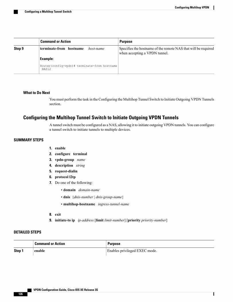
PurposeCommand or Action
Specifies the hostname of the remote NAS that will be requiredwhen accepting a VPDN tunnel.
terminate-from hostname host-name
Example:
Router(config-vpdn)# terminate-from hostnameNAS12
Step 9
What to Do Next
Youmust perform the task in the Configuring theMultihop Tunnel Switch to Initiate Outgoing VPDNTunnelssection.
Configuring the Multihop Tunnel Switch to Initiate Outgoing VPDN TunnelsA tunnel switchmust be configured as a NAS, allowing it to initiate outgoing VPDN tunnels. You can configurea tunnel switch to initiate tunnels to multiple devices.
SUMMARY STEPS
1. enable2. configure terminal3. vpdn-group name4. description string5. request-dialin6. protocol l2tp7. Do one of the following:
• domain domain-name
• dnis {dnis-number | dnis-group-name}
• multihop-hostname ingress-tunnel-name
8. exit9. initiate-to ip ip-address [limit limit-number] [priority priority-number]
DETAILED STEPS
PurposeCommand or Action
Enables privileged EXEC mode.enableStep 1
VPDN Configuration Guide, Cisco IOS XE Release 3S126
Configuring Multihop VPDNConfiguring a Multihop Tunnel Switch

PurposeCommand or Action
Example:
Router> enable
• Enter your password if prompted.
Enters global configuration mode.configure terminal
Example:
Router# configure terminal
Step 2
Creates a VPDN group and enters VPDN group configuration mode.vpdn-group name
Example:
Router(config)# vpdn-group 1
Step 3
(Optional) Adds a description to a VPDN group.description string
Example:
Router(config-vpdn)# descriptionmyvpdngroup
Step 4
Configures a tunnel switch to request the establishment of a tunnel toa tunnel server, creates a request-dialin VPDN subgroup, and entersVPDN request dial-in subgroup configuration mode.
request-dialin
Example:
Router(config-vpdn)# request-dialin
Step 5
Specifies the Layer 2 Tunneling Protocol that the VPDN group willuse.
protocol l2tp
Example:
Router(config-vpdn-req-in)# protocoll2tp
Step 6
Requests that PPP calls from a specific domain name be tunneled.Do one of the following:Step 7
or• domain domain-nameRequests that PPP calls from a specific DNIS number or DNIS groupbe tunneled.
• dnis {dnis-number | dnis-group-name}
• multihop-hostnameingress-tunnel-name or
Enables the tunnel switch to initiate a tunnel based on the NAS hostname or the ingress tunnel ID.
Example:
Router(config-vpdn-req-in)# domaincompany.com
If you use themultihop-hostname command to configureyour tunnel switch, you must configure vpdn search-ordercommand with themultihop-hostname keyword. For moreinformation on configuring the VPDN tunnel authorizationsearch order, see the Configuring AAA for VPDNs module.
Note
VPDN Configuration Guide, Cisco IOS XE Release 3S 127
Configuring Multihop VPDNConfiguring a Multihop Tunnel Switch

PurposeCommand or Action
Example:
Router(config-vpdn-req-in)# dnis 5687
Example:
Router(config-vpdn-req-in)#multihop-hostname nas1
Exits to VPDN group configuration mode.exit
Example:
Router(config-vpdn-req-in)# exit
Step 8
Specifies an IP address that will be used for Layer 2 tunneling.initiate-to ip ip-address [limit limit-number][priority priority-number]
Step 9
• limit --Maximum number of connections that can be made to thisIP address.
Example:
Router(config-vpdn)# initiate-to ip10.1.1.1 limit 12
• priority --Priority for this IP address.
The priority keyword is typically not configured on a tunnelswitch. Information used for load balancing and failover isconfigured on a remote authentication, authorization, andaccounting (AAA) server instead. For more information aboutconfiguring load balancing and failover priorities using aremote AAA server, see the Configuring AAA for VPDNsmodule.
Note
• Multiple tunnel servers can be configured on the tunnel switch byconfiguring multiple initiate-to commands.
Configuration Examples for Multihop VPDN
Example Configuring Multihop VPDN Tunnel SwitchingThe following example configures a NAS, tunnel switch, and tunnel server to establish a multihop VPDNtunnel using L2TP:
NAS Configuration
! Configure the NAS to initiate VPDN dial-in sessions to the tunnel switchvpdn-group 1
VPDN Configuration Guide, Cisco IOS XE Release 3S128
Configuring Multihop VPDNConfiguration Examples for Multihop VPDN

request-dialinprotocol l2tpdomain cisco.com
!initiate-to ip 172.22.66.25local name ISP-NAS
Tunnel Switch Configuration
!Enable VPDNvpdn enable!!Enable multihopvpdn multihop
!
! Configure the tunnel switch to use the multihop hostname in the authentication search.
vpdn search-order multihop-hostname domain dnis
!
! Configure the tunnel switch to accept dial-in sessions from the NASvpdn-group tunnelinaccept-dialinprotocol l2tpvirtual-template 1
!terminate-from hostname ISP-NASlocal name ISP-Sw!! Configure the tunnel switch to initiate VPDN dial-in sessions to the tunnel servervpdn-group tunneloutrequest-dialinprotocol l2tpmultihop-hostname ISP-NAS
!initiate-to ip 10.2.2.2local name ISP-Sw
Tunnel Server Configuration
! Configure the tunnel server to accept dial-in sessions from the NASvpdn-group 1accept-dialinprotocol l2tpvirtual-template 1
!terminate-from hostname ISP-Swlocal name ENT-TS
Where to Go NextYou can perform any of the relevant optional tasks in the Configuring Additional VPDN Features and in theVPDN Tunnel Management modules.
VPDN Configuration Guide, Cisco IOS XE Release 3S 129
Configuring Multihop VPDNWhere to Go Next

Additional ReferencesRelated Documents
Document TitleRelated Topic
Cisco IOS Master Commands List, All ReleasesCisco IOS commands
Cisco IOS VPDN Command ReferenceVPDN commands
VPDN Technology OverviewVPDN technology overview
Cisco IOS Broadband Access Aggregation and DSLCommand Reference
Broadband access aggregation and DSL commands
Standards
TitleStandard
--No new or modified standards are supported by thisfeature, and support for existing standards has notbeen modified by this feature.
MIBs
MIBs LinkMIB
To locate and downloadMIBs for selected platforms,Cisco software releases, and feature sets, use CiscoMIB Locator found at the following URL:
http://www.cisco.com/go/mibs
No new or modified MIBs are supported by thisfeature, and support for existing MIBs has not beenmodified by this feature.
RFCs
TitleRFC
Layer Two Tunneling Protocol (L2TP)RFC 2661
VPDN Configuration Guide, Cisco IOS XE Release 3S130
Configuring Multihop VPDNAdditional References

Technical Assistance
LinkDescription
http://www.cisco.com/cisco/web/support/index.htmlThe Cisco Support and Documentation websiteprovides online resources to download documentation,software, and tools. Use these resources to install andconfigure the software and to troubleshoot and resolvetechnical issues with Cisco products and technologies.Access to most tools on the Cisco Support andDocumentation website requires a Cisco.com user IDand password.
Feature Information for Multihop VPDNThe following table provides release information about the feature or features described in this module. Thistable lists only the software release that introduced support for a given feature in a given software releasetrain. Unless noted otherwise, subsequent releases of that software release train also support that feature.
Use Cisco Feature Navigator to find information about platform support and Cisco software image support.To access Cisco Feature Navigator, go to www.cisco.com/go/cfn. An account on Cisco.com is not required.
Table 11: Feature Information for Multihop VPDN
Feature Configuration InformationSoftware ReleasesFeature Name
This feature was introduced onCisco ASR 1000 Series Routers.
Multihop VPDN is a specializedVPDN configuration that allowspackets to pass through multipletunnels. Ordinarily, packets are notallowed to pass through more thanone tunnel. In a multihopdeployment, the VPDN tunnel isterminated after each hop and anew tunnel is initiated to the nexthop destination.
No commands were introduced ormodified by this feature.
Cisco IOS XE Release 2.2Multihop VPDN
VPDN Configuration Guide, Cisco IOS XE Release 3S 131
Configuring Multihop VPDNFeature Information for Multihop VPDN

Feature Configuration InformationSoftware ReleasesFeature Name
This feature provides flexibility onwhere and how many subscribersare connected to available servicesand how those services are defined.The primary focus of SSS is todirect PPP from one point toanother using a Layer 2 subscriberpolicy. The policy will managetunneling of PPP in a policy-basedbridging fashion.
The following VPDN commandswere introduced ormodified by thisfeature:
multihop-hostname and vpdnsearch-order.
Cisco IOS XE Release 2.2.1Subscriber Service Switch
VPDN Configuration Guide, Cisco IOS XE Release 3S132
Configuring Multihop VPDNFeature Information for Multihop VPDN

C H A P T E R 5Configuring Additional VPDN Features
This module documents concepts and tasks associated with configuring additional virtual private dialupnetwork (VPDN) features. These optional features are used in combination with a VPDN deployment, andrequire that a VPDN deployment is first configured:
• VPDN Template
• VPDN Source IP Address
• VRF-Aware VPDN Tunnels
• MTU Tuning for L2TP VPDN Tunnels
• QoS for VPDN Tunnels
• VPDN Group Selection
All of the tasks documented in this module require that tasks documented elsewhere in the Cisco IOS XEVPDN Configuration Guide have first been completed.
• Finding Feature Information, page 133
• Information About Configuring Additional VPDN Features, page 134
• How to Configure Additional VPDN Features, page 139
• Configuration Examples for Additional VPDN Features, page 163
• Where to Go Next, page 171
• Additional References, page 171
• Feature Information for Additional VPDN Features, page 173
Finding Feature InformationYour software release may not support all the features documented in this module. For the latest caveats andfeature information, see Bug Search Tool and the release notes for your platform and software release. Tofind information about the features documented in this module, and to see a list of the releases in which eachfeature is supported, see the feature information table.
VPDN Configuration Guide, Cisco IOS XE Release 3S 133

Use Cisco Feature Navigator to find information about platform support and Cisco software image support.To access Cisco Feature Navigator, go to www.cisco.com/go/cfn. An account on Cisco.com is not required.
Information About Configuring Additional VPDN Features
VPDN TemplateA VPDN template can be configured with global default values that will supersede the system default values.These global default values are applied to all VPDN groups, unless specific values are configured for individualVPDN groups.
Multiple named VPDN templates can be configured in addition to a single global (unnamed) VPDN template.A VPDN group can be associated with only one VPDN template.
Values configured in the global VPDN template are applied to all VPDN groups by default. A VPDN groupcan be disassociated from the global VPDN template, or associated with a named VPDN template. Associatinga VPDN group with a named VPDN template automatically disassociates it from the global VPDN template.
The default hierarchy for the application of VPDN parameters to a VPDN group is as follows:
• VPDN parameters configured for the individual VPDN group are always applied to that VPDN group.
• VPDN parameters configured in the associated VPDN template are applied for any settings not specifiedin the individual VPDN group configuration.
• System default settings for VPDN parameters are applied for any settings not configured in the individualVPDN group or the associated VPDN template.
Individual VPDN groups can be disassociated from the associated VPDN template if desired, allowing thesystem default settings to be used for any parameters not configured in that individual VPDN group.
VPDN Source IP AddressA tunnel endpoint can be configured with a source IP address that is different from the IP address used toopen the VPDN tunnel. When a source IP address is configured on a tunnel endpoint, the router will generateVPDN packets labeled with the configured source IP address. A source IP address might need to be configuredif the tunnel endpoints are managed by different companies and addressing requirements necessitate that aparticular IP address be used.
The source IP address can be configured globally, or for an individual VPDN group. The VPDN groupconfiguration will take precedence over the global configuration.
VPN Routing Forwarding (VRF) Framed Route (Pool) Assignment via PPPThe VPN Routing Forwarding (VRF) Framed Route (Pool) Assignment via PPP feature introduces supportto make these RADIUS attributes VRF aware: attribute 22 (Framed-Route), a combination of attribute 8(Framed-IP-Address) and attribute 9 (Framed-IP-Netmask), and the Cisco VSA route command. Thus, staticIP routes can be applied to a particular VRF routing table rather than the global routing table.
VPDN Configuration Guide, Cisco IOS XE Release 3S134
Configuring Additional VPDN FeaturesInformation About Configuring Additional VPDN Features
VRF-Aware VPDN TunnelsPrior to Cisco IOS XE Release 2.2, you had to specify IP addresses from the global routing table for theendpoints of a VPDN tunnel. VRF-aware VPDN tunnels provide support for VPDN tunnels that terminateon a Virtual Private Network (VPN) routing and forwarding (VRF) instance by allowing you to use IP addressesfrom a VRF routing table.
VRF-aware VPDN tunnels enhance the support of VPDN tunnels by allowing VPDN tunnels to start outsidea Multiprotocol Label Switching (MPLS) VPN and terminate within the MPLS VPN and have overlappingIP addresses. For example, this feature allows you to use a VRF address from a customer VRF as the destinationaddress.
Beginning with Cisco IOS XE Release 2.2, the VRF-Aware VPDN Tunnels feature adds support for L2TPon the LNS. The initiation and termination of tunnels in a VRF instance is supported on the Cisco ASR 1000Series Aggregation Services Routers in both an LNS and Layer 2 Access Concentrator (LAC) environment.
You can use VRF-aware VPDN tunnels with multihop and dial-in VPDN tunneling scenarios. In a multihopscenario, this feature is sometimes referred to as VRF-aware VPDN multihop.
MTU Tuning for L2TP VPDN TunnelsFragmentation and reassembly of packets is done at the process level in the software. When a tunnel serveris aggregating large numbers of sessions and traffic flows, process switching can dramatically reduceperformance. For this reason, it is highly desirable to reduce or eliminate the need for packet fragmentationand reassembly in a VPDN deployment, and instead move the burden of any required packet reassembly tothe client devices.
Packets are fragmented when they attempt to pass through an egress interface with a maximum transmissionunit (MTU) that is smaller than the size of the packet. By default, the MTU of most interface is 1500 bytes.Because of this default MTU size, TCP segments are created with a default payload of 1460 bytes, allowingroom for the 40 byte TCP/IP header. Because L2TP encapsulation adds 40 bytes of header information,tunneled packets will exceed the MTU of an interface if MTU tuning is not performed.
In order to reach its final destination, a packet might traverse multiple egress interfaces. The path MTU isdefined as the smallest MTU of all of the interfaces that the packet must pass through.
A number of different methods are available to performMTU tuning. Their end goal is to prevent fragmentationof packets after they have been encapsulated for tunneling. These methods take advantage of distinctmechanisms to accomplish this, as described in these sections:
MTU Tuning Using IP MTU AdjustmentsThe IP MTU configuration controls the maximum size of a packet allowed to be encapsulated by a Layer 2protocol. The IP MTU of an interface can be manually lowered to compensate for the size of the L2TP headerif the path MTU is known.
A router can also be configured to automatically adjust the IP MTU of an interface to compensate for the sizeof the L2TP header. The automatic adjustment corrects for the size of the L2TP header based on the MTU ofthe egress interface of that device. This configuration is effective only in preventing fragmentation when theMTU of that interface is the same as the path MTU.
VPDN Configuration Guide, Cisco IOS XE Release 3S 135
Configuring Additional VPDN FeaturesVRF-Aware VPDN Tunnels

MTU Tuning Using Path MTU DiscoveryIf the path MTU between the NAS and the tunnel server is unknown, or if it changes, path MTU discovery(PMTUD) can be used to perform MTU tuning. PMTUD uses the Don't Fragment (DF) bit in the IP headerto dynamically discover the smallest MTU among all the interfaces along a routing path.
The source host initially assumes that the path MTU is the knownMTU of the first egress interface, and sendsall packets on that path with the DF bit in the IP header set. If any of the packets are too large to be forwardedwithout fragmentation by the interface of a device along the path, that device will discard the packet and returnan Internet ControlMessage Protocol (ICMP) Destination Unreachablemessage to the source host. The ICMPDestination Unreachable message includes code 4, which means fragmentation needed and DF set, andindicates the IP MTU of the interface that was unable to forward the packet without fragmentation. Thisinformation allows the source host to reduce the size of the packet before retransmission to allow it to fitthrough that interface.
Enabling PMTUD makes VPDN deployments vulnerable to Denial of Service (DoS) attacks that use craftedICMP messages to set a connection’s path MTU to an impractically low value. This will cause higher layerprotocols to time out because of a very low throughput, even though the connection is still in the establishedstate. This type of attack is classified as a throughput-reduction attack. For more information onthroughput-reduction attacks against L2TP VPDN deployments, see the "Additional References" section.
To protect against a throughput-reduction attack, a range of acceptable values for the path MTU can bespecified. If the device receives an ICMP code 4 message that advertises a next-hop path MTU that fallsoutside the configured size range, the device will ignore the message.
PMTUD can be unreliable and might fail when performed over the Internet because some routers or firewallsare configured to filter out all ICMP messages. When the source host does not receive an ICMP destinationunreachable message from a device that is unable to forward a packet without fragmentation, it will not knowto reduce the packet size. The source host will continue to retransmit the same large packet. Because the DFbit is set, these packets will be continually dropped because they exceed the path MTU, and the connectionwill stop responding.
MTU Tuning Using TCP MSS AdvertisingBecause PMTUD can be unreliable, an alternate method of performing MTU tuning was introduced. Thismethod ofMTU tuning takes advantage of TCPMaximumSegment Size (MSS) advertisements in the incomingand outgoing synchronize (SYN) packets sent by the end hosts.
The TCPMSS defines the maximum amount of data that a host is willing to accept in a single TCP/IP datagram.The MSS value is sent as a TCP header option only in TCP SYN segments. Each side of a TCP connectionreports its MSS value to the other side. The sending host is required to limit the size of data in a single TCPsegment to a value less than or equal to the MSS reported by the receiving host.
If you configure a lower TCP MSS than the usual default of 1460, the size of TCP segments will be reducedto compensate for the information added by the L2TP header.
MTU Tuning Using PPP MRU AdvertisingAnother option for reducing fragmentation in an L2TP VPDN network requires that Maximum Receive Unit(MRU) negotiation is supported by the PPP client. One known client which supports MRU negotiations isthe Windows XP PPP client. Unfortunately, other commonly deployed PPP clients do not adhere to theadvertised PPPMRU as they should. To determine if your PPP client properly responds to the advertised PPPMRU, see the PPP client documentation.
VPDN Configuration Guide, Cisco IOS XE Release 3S136
Configuring Additional VPDN FeaturesMTU Tuning for L2TP VPDN Tunnels

PPPMRU allows a peer to advertise its maximum receive unit, which is derived from the MTU configurationon the virtual template interface. A device will not process a PPP frame with a payload larger than its advertisedMRU. The Cisco PPP implementation uses the MTU of the interface as the advertised MRU value duringPPP negotiations.
The MTU of a virtual template interface can be manually lowered to compensate for the size of the L2TPheader. If the PPP peer listens to the MRU advertised during PPP negotiation, it will adjust its MTU (andindirectly its IP MTU) for that PPP link. This in turn will modify the TCP MSS that the peer advertises whenopening up TCP connections.
Because the default MTU for an interface is 1500 bytes, the default MRU is 1500 bytes. Setting the MTU ofan interface to 1460 changes the advertised MRU to 1460. This configuration would tell the peer to allowroom for a 40-byte L2TP header.
One issue with lowering theMTU on the virtual-template interface is that the IPMTU is automatically loweredas well. It is not possible to configure an IP MTU greater than the MTU on a virtual template interface. Thiscan be an issue if there is a mixture of peer devices that do and do not adjust their MTU based on the advertisedMRU. The clients that are unable to listen to MRU advertisements and adjust accordingly will continue tosend full-sized packets to the peer. Packets that are larger than the lowered IP MTU, yet smaller than thenormal default IP MTU, will be forced to fragment. For example, an L2TP packet that is 1490 bytes wouldnormally be transmitted without fragmentation. If the MTU has been lowered to 1460 bytes, this packet willbe unnecessarily fragmented. In this situation, it would be optimal to advertise a lower MRU to those clientsthat are capable of listening and adjusting, yet still allow full-sized packets for those clients that are unableto adjust.
Clients that ignore the advertisedMRUmight experience the PMTUDproblems described in theMTUTuningUsing IP MTU Adjustments, on page 135. PMTUD can be turned off by clearing the DF bit on the inner IPpacket.
QoS for VPDN TunnelsQuality of service (QoS) packet classification features provide the capability to partition network traffic intomultiple priority levels or classes of service. Packet classifications provide the information required to coordinateQoS from end to end within and between networks. Packet classifications are used by other QoS features toassign the appropriate traffic handling policies, including congestion management, bandwidth allocation, anddelay bounds for each traffic class.
Packets can be marked for end-to-end QoS using the type of service (ToS) byte in the IP header. The firstthree bits of the ToS byte are used for IP precedence settings. Four of the remaining five bits are used to setthe ToS. The remaining bit of the ToS byte is unassigned.
In a VPDN deployment, IP packets might be classified by an external source such as the customer networkor a downstream client. By default, a tunnel endpoint will set the ToS byte in the Layer 2 header to zero,specifying normal service. Depending on the VPDN deployment, you can choose to configure your VPDNnetwork to do one of the following in regard to QoS classifications:
• Ignore existing QoS classifications by leaving the default configuration in place.
• Preserve existing QoS classifications by configuring the tunnel endpoint to copy the ToS byte from theIP header to the Layer 2 header.
• Configure QoS classifications specific to your VPDN network.
These sections provide additional information on QoS options for VPDN deployments:
VPDN Configuration Guide, Cisco IOS XE Release 3S 137
Configuring Additional VPDN FeaturesQoS for VPDN Tunnels

QoS Classification PreservationWhen Layer 2 packets are created the ToS byte value is set to zero by default, indicating normal service. Thissetting ignores the values of the ToS byte of the encapsulated IP packets that are being tunneled. The tunnelserver can be configured to copy the contents of the ToS field of the inner IP packets to the ToS byte of theLayer 2 header. Copying the ToS field from the IP header to the Layer 2 header preserves end-to-end QoSfor tunneled packets.
IP Precedence for VPDN TunnelsIP precedence settings mark the class of service (CoS) for a packet. The three precedence bits in the ToS fieldof the IP header can be used to define up to six classes of service. If you choose to manually configure aspecific IP precedence value for Layer 2 packets, QoS will not be preserved end-to-end across the tunnel.
ToS Classification for VPDN TunnelsThe ToS bits mark the ToS classification for a packet. Each of the four bits controls a particular aspect of theToS--reliability, throughput, delay, and cost. If you choose to manually configure a specific ToS value forLayer 2 packets, QoS will not be preserved end-to-end across the tunnel.
VPDN Group SelectionThe VPDN Group Selection feature allows configuration of multiple VPDN tunnels, between a LAC andLNS, with different VPDN group configurations.
The VPDNGroup Selection feature introduces two new keys that allow an LNS to connect to multiple VPDNtunnels from the same LAC, and to bind to different VPDN groups that use a different VPDN template forcustomized configurations. These keys are:
• Destination IP address the L2TP Start-Control-Connection-Request (SCCRQ) was received on
• The virtual routing and forwarding (VRF) instance the SCCRQ was received on
The VPDN Group Selection feature allows the LAC to build VPDN tunnels to either different IP addressesor different VRFs.
Benefits of VPDN Group SelectionThe VPDN Group Selection feature allows SPs to support multiple VPDN groups or tunnels between a LACand LNS by using the new VPDN group selection keys destination IP address or VRF ID, in addition to thepreviously supported hostname selection key. The VPDN Group Selection feature enables SPs to providecustomize configurations for each VPDN tunnel.
VPDN Configuration Guide, Cisco IOS XE Release 3S138
Configuring Additional VPDN FeaturesVPDN Group Selection

How to Configure Additional VPDN Features
Creating a VPDN TemplatePerform this task on the NAS or the tunnel server to create a VPDN template. If you remove a named VPDNtemplate configuration, all VPDN groups that were associated with it will automatically be associated withthe global VPDN template.
Note • An L2TP tunnel must be established for the VPDN template settings to be used. Once a tunnel hasbeen established, changes in the VPDN template settings will not have an effect on the tunnel untilit is brought down and reestablished.
• Not all commands that are available for configuring a VPDN group can be used to configure a VPDNtemplate. For a list of the commands that can be used in VPDN template configuration mode, usethe ? command in VPDN template configuration mode.
SUMMARY STEPS
1. enable2. configure terminal3. vpdn-template [name]
DETAILED STEPS
PurposeCommand or Action
Enables privileged EXEC mode.enableStep 1
Example:
Router> enable
• Enter your password if prompted.
Enters global configuration mode.configure terminal
Example:
Router# configure terminal
Step 2
Creates a VPDN template and enters VPDN templateconfiguration mode.
vpdn-template [name]
Example:
Router(config)# vpdn-template l2tp
Step 3
VPDN Configuration Guide, Cisco IOS XE Release 3S 139
Configuring Additional VPDN FeaturesHow to Configure Additional VPDN Features

Associating a VPDN Group with a VPDN TemplateVPDN groups are associated with the global VPDN template by default. Individual VPDN groups can beassociated with a named VPDN template instead. Associating a VPDN group with a named VPDN templatedisassociates the VPDN group from the global VPDN template.
Perform this task on the NAS or the tunnel server to associate a specific VPDN group with a named VPDNtemplate, or to reassociate a VPDN group with the global VPDN template if it has been previously disassociatedfrom the global VPDN template.
Before You Begin
• Create and enable the VPDN template. For details, see the "Creating a VPDN Template" section.
SUMMARY STEPS
1. enable2. configure terminal3. vpdn-group name4. source vpdn-template [name]
DETAILED STEPS
PurposeCommand or Action
Enables privileged EXEC mode.enableStep 1
Example:
Router> enable
• Enter your password if prompted.
Enters global configuration mode.configure terminal
Example:
Router# configure terminal
Step 2
Creates a VPDN group and enters VPDN group configuration mode.vpdn-group name
Example:
Router(config)# vpdn-group l2tp
Step 3
Associates a VPDN group with a VPDN template.source vpdn-template [name]Step 4
Example:
Router(config-vpdn)# sourcevpdn-template l2tp
• VPDN groups are associated with the unnamed VPDN templateby default.
• If you have disassociated a VPDN group from the VPDN templateusing the no source vpdn-template command, you can reassociateit by issuing the source vpdn-template command.
VPDN Configuration Guide, Cisco IOS XE Release 3S140
Configuring Additional VPDN FeaturesAssociating a VPDN Group with a VPDN Template

PurposeCommand or Action
• Associating a VPDN group with a named VPDN templatedisassociates it from the global VPDN template.
Disassociating a VPDN Group from the VPDN TemplateIndividual VPDN groups can be disassociated from the VPDN template if desired, allowing the system defaultsettings to be used for any parameters not configured in the individual VPDN group.
Perform this task on the NAS or the tunnel server to disassociate a specific VPDN group from any VPDNtemplate.
SUMMARY STEPS
1. enable2. configure terminal3. vpdn-group name4. no source vpdn-template [name]
DETAILED STEPS
PurposeCommand or Action
Enables privileged EXEC mode.enableStep 1
Example:
Router> enable
• Enter your password if prompted.
Enters global configuration mode.configure terminal
Example:
Router# configure terminal
Step 2
Creates a VPDN group and enters VPDN group configuration mode.vpdn-group name
Example:
Router(config)# vpdn-group l2tp
Step 3
VPDN Configuration Guide, Cisco IOS XE Release 3S 141
Configuring Additional VPDN FeaturesDisassociating a VPDN Group from the VPDN Template

PurposeCommand or Action
Configures an individual VPDN group to use system default settings ratherthan the VPDN template settings for all unspecified parameters.
no source vpdn-template [name]
Example:
Router(config-vpdn)# no sourcevpdn-template l2tp
Step 4
• VPDN groups are associated with the unnamed VPDN template bydefault. Use the no source vpdn-template command to disassociatea VPDN group from its associated VPDN template.
• If you have disassociated a VPDN group from the VPDN templateusing the no source vpdn-template command, you can reassociateit by issuing the source vpdn-template command.
Configuring the VPDN Source IP AddressPerform one of these tasks to configure a source IP address on a NAS or a tunnel server:
Configuring the Global VPDN Source IP AddressYou can configure a single global source IP address on a device. If a source IP address is configured for aVPDN group, the global source IP address will not be used for tunnels belonging to that VPDN group.
Perform this task on a tunnel endpoint to configure the global source IP address.
SUMMARY STEPS
1. enable2. configure terminal3. vpdn source-ip ip-address
DETAILED STEPS
PurposeCommand or Action
Enables privileged EXEC mode.enableStep 1
Example:
Router> enable
• Enter your password if prompted.
Enters global configuration mode.configure terminal
Example:
Router# configure terminal
Step 2
VPDN Configuration Guide, Cisco IOS XE Release 3S142
Configuring Additional VPDN FeaturesConfiguring the VPDN Source IP Address

PurposeCommand or Action
Globally specifies an IP address that is different from thephysical IP address used to open a VPDN tunnel.
vpdn source-ip ip-address
Example:
Router(config)# vpdn source-ip 10.1.1.1
Step 3
Configuring the Source IP Address for a VPDN GroupYou can configure a source IP address for a specific VPDN group. If a source IP address is configured for aVPDN group, the global source IP address will not be used for tunnels belonging to that VPDN group.
Perform this task on a tunnel endpoint to configure a source IP address for a specific VPDN group.
SUMMARY STEPS
1. enable2. configure terminal3. vpdn-group name4. source-ip ip-address
DETAILED STEPS
PurposeCommand or Action
Enables privileged EXEC mode.enableStep 1
Example:
Router> enable
• Enter your password if prompted.
Enters global configuration mode.configure terminal
Example:
Router# configure terminal
Step 2
Creates a VPDN group and enters VPDN group configurationmode.
vpdn-group name
Example:
Router(config)# vpdn-group 1
Step 3
VPDN Configuration Guide, Cisco IOS XE Release 3S 143
Configuring Additional VPDN FeaturesConfiguring the VPDN Source IP Address

PurposeCommand or Action
Specifies an IP address that is different from the physical IPaddress used to open a VPDN tunnel for the tunnels associatedwith a VPDN group.
source-ip ip-address
Example:
Router(config-vpdn)# source-ip 10.1.1.1
Step 4
Configuring VRF-Aware VPDN TunnelingVRF-aware VPDN tunneling can be configured locally on a NAS, tunnel server, or multihop tunnel switch,or it can be configured in the remote RADIUS server profile. Configuring VRF-aware VPDN tunneling inthe RADIUS server profile will propagate the configuration only to a NAS or multihop tunnel switch. Toconfigure VRF-aware VPDN tunnels on a tunnel server, you must configure the tunnel server locally.
Perform one of these tasks to configure a VRF-aware VPDN tunnel:
Configuring VRF-Aware VPDN Tunneling LocallyVRF-aware VPDN tunneling can be configured locally on a NAS, a tunnel server, or a multihop tunnel switch.Configuring VRF-aware VPDN tunneling on a device specifies that the tunnel endpoint IP addresses configuredfor that VPDN group belong to the specified VRF routing table rather than the global routing table.
Perform this task on the multihop tunnel switch, the NAS, or the tunnel server to configure a VPDN tunnelto belong to a VRF.
Before You Begin
• A multihop, dial-in, or dial-out L2TP VPDN tunneling deployment must be configured.
• The source IP address and the destination IP address configured in the L2TP VPDN group must existin the specified VPN.
• Because VRFs use Cisco Express Forwarding, you must configure Cisco Express Forwarding beforeperforming this task.
L2TP is the only tunneling protocol supported for VRF-aware VPDN tunneling.Note
SUMMARY STEPS
1. enable2. configure terminal3. vpdn-group name4. vpn {vrf vrf-name | id vpn-id}
VPDN Configuration Guide, Cisco IOS XE Release 3S144
Configuring Additional VPDN FeaturesConfiguring VRF-Aware VPDN Tunneling

DETAILED STEPS
PurposeCommand or Action
Enables privileged EXEC mode.enableStep 1
Example:
Router> enable
• Enter your password if prompted.
Enters global configuration mode.configure terminal
Example:
Router# configure terminal
Step 2
Creates a VPDN group and enters VPDN group configurationmode.
vpdn-group name
Example:
Router(config)# vpdn-group mygroup
Step 3
Specifies that the source and destination IP addresses of a givenVPDN group belong to a specified VRF instance.
vpn {vrf vrf-name | id vpn-id}
Example:
Router(config-vpdn)# vpn vrf myvrf
Step 4
• vrf vrf-name --Specifies the VRF instance by the VRFname.
• id vpn-id --Specifies the VRF instance by the VPN ID.
Configuring VRF-Aware VPDN Tunneling on the Remote RADIUS AAA ServerVRF-aware VPDN tunneling can be configured in the remote RADIUS server profile. Configuring VRF-awareVPDN tunneling on a device specifies that the tunnel endpoint IP addresses configured for that VPDN groupbelong to the specified VRF routing table rather than the global routing table.
Configuring VRF-aware VPDN tunneling in the RADIUS server profile will propagate the configuration onlyto a NAS or multihop tunnel switch. To configure VRF-aware VPDN tunnels on a tunnel server, you mustconfigure the tunnel server locally by performing the task in the Configuring VRF-Aware VPDN TunnelingLocally section.
Perform this task on the remote RADIUS server. The tunnel attributes configured in the RADIUS serverprofile will be propagated to the NAS or multihop tunnel switch.
Before You Begin
• A multihop, dial-in, or dial-out L2TP VPDN tunneling deployment must be configured.
• The source IP address and the destination IP address configured in the L2TP VPDN group must existin the specified VPN.
VPDN Configuration Guide, Cisco IOS XE Release 3S 145
Configuring Additional VPDN FeaturesConfiguring VRF-Aware VPDN Tunneling

• Because VRFs use Cisco Express Forwarding, you must configure Cisco Express Forwarding beforeperforming this task.
• The NAS or tunnel switch must be configured for remote RADIUS AAA. Perform the tasks in theConfiguring AAA on the NAS and the Tunnel Server and Configuring Remote AAA for VPDNs sectionsin the Configuring AAA for VPDNs module to configure the NAS for remote RADIUS AAA.
• The RADIUS server must be configured for AAA.
L2TP is the only tunneling protocol supported for VRF-aware VPDN tunneling.Note
SUMMARY STEPS
1. Cisco-Avpair = vpdn:tunnel-id= name2. Cisco-Avpair = vpdn:tunnel-type= l2tp3. Cisco-Avpair = vpdn:vpn-vrf= vrf-name4. Cisco-Avpair = vpdn:l2tp-tunnel-password= secret
DETAILED STEPS
PurposeCommand or Action
Specifies the tunnel ID in the RADIUS user profile.Cisco-Avpair = vpdn:tunnel-id= name
Example:
Cisco-Avpair = vpdn:tunnel-id=test
Step 1
Specifies L2TP as the tunneling protocol in the RADIUSuser profile.
Cisco-Avpair = vpdn:tunnel-type= l2tp
Example:
Cisco-Avpair = vpdn:tunnel-type=l2tp
Step 2
Specifies the VRF instance that the VPDN tunnel shouldbe associated with using the VRF name in the RADIUSuser profile.
Cisco-Avpair = vpdn:vpn-vrf= vrf-name
Example:
or
Step 3
or
Specifies the VRF instance that the VPDN tunnel shouldbe associated with using the VPN ID in the RADIUSuser profile.
Example:
Cisco-Avpair = vpdn:vpn-id=
vpn-id
VPDN Configuration Guide, Cisco IOS XE Release 3S146
Configuring Additional VPDN FeaturesConfiguring VRF-Aware VPDN Tunneling
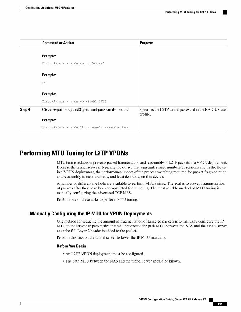
PurposeCommand or Action
Example:
Cisco-Avpair = vpdn:vpn-vrf=myvrf
Example:
or
Example:
Cisco-Avpair = vpdn:vpn-id=A1:3F6C
Specifies the L2TP tunnel password in the RADIUS userprofile.
Cisco-Avpair = vpdn:l2tp-tunnel-password= secret
Example:
Cisco-Avpair = vpdn:l2tp-tunnel-password=cisco
Step 4
Performing MTU Tuning for L2TP VPDNsMTU tuning reduces or prevents packet fragmentation and reassembly of L2TP packets in a VPDN deployment.Because the tunnel server is typically the device that aggregates large numbers of sessions and traffic flowsin a VPDN deployment, the performance impact of the process switching required for packet fragmentationand reassembly is most dramatic, and least desirable, on this device.
A number of different methods are available to perform MTU tuning. The goal is to prevent fragmentationof packets after they have been encapsulated for tunneling. The most reliable method of MTU tuning ismanually configuring the advertised TCP MSS.
Perform one of these tasks to perform MTU tuning:
Manually Configuring the IP MTU for VPDN DeploymentsOne method for reducing the amount of fragmentation of tunneled packets is to manually configure the IPMTU to the largest IP packet size that will not exceed the path MTU between the NAS and the tunnel serveronce the full Layer 2 header is added to the packet.
Perform this task on the tunnel server to lower the IP MTU manually.
Before You Begin
• An L2TP VPDN deployment must be configured.
• The path MTU between the NAS and the tunnel server should be known.
VPDN Configuration Guide, Cisco IOS XE Release 3S 147
Configuring Additional VPDN FeaturesPerforming MTU Tuning for L2TP VPDNs

SUMMARY STEPS
1. enable2. configure terminal3. interface virtual-template number4. ip mtu bytes
DETAILED STEPS
PurposeCommand or Action
Enables privileged EXEC mode.enableStep 1
Example:
Router> enable
• Enter your password if prompted.
Enters global configuration mode.configure terminal
Example:
Router# configure terminal
Step 2
Creates a virtual template interface that can be configured andapplied dynamically in creating virtual access interfaces and entersinterface configuration mode.
interface virtual-template number
Example:
Router(config)# interface virtual-template1
Step 3
Sets the MTU size of IP packets sent on an interface.ip mtu bytesStep 4
Example:
Router(config-if)# ip mtu 1460
Because Layer 2 headers are 40 bytes, the recommendedvalue for the bytes argument is 1460.
Note
Enabling Automatic Adjustment of the IP MTU for VPDN DeploymentsA tunnel server can be configured to automatically adjust the IP MTU of an interface to compensate for thesize of the Layer 2 header. The automatic adjustment corrects for the size of the Layer 2 header based on theMTU of the egress interface of that device. This configuration is effective in preventing fragmentation onlywhen the MTU of that interface is the same as that of the path MTU.
Perform this task on the tunnel server to enable automatic adjustment of the IP MTU.
Before You Begin
• A VPDN deployment must be configured.
VPDN Configuration Guide, Cisco IOS XE Release 3S148
Configuring Additional VPDN FeaturesPerforming MTU Tuning for L2TP VPDNs

Note • Automatic adjustment of the IP MTU is disabled by default.
• The IPMTU is automatically adjusted only if there is no IPMTU configured manually on the virtualtemplate interface.
SUMMARY STEPS
1. enable2. configure terminal3. vpdn-group name4. ip mtu adjust
DETAILED STEPS
PurposeCommand or Action
Enables privileged EXEC mode.enableStep 1
Example:
Router> enable
• Enter your password if prompted.
Enters global configuration mode.configure terminal
Example:
Router# configure terminal
Step 2
Creates a VPDN group and enters VPDN groupconfiguration mode.
vpdn-group name
Example:
Router(config)# vpdn-group 1
Step 3
Enables automatic adjustment of the IP MTU on a virtualaccess interface.
ip mtu adjust
Example:
Router(config-vpdn)# ip mtu adjust
Step 4
Enabling Path MTU Discovery for VPDNsIf the path MTU between the NAS and the tunnel server is variable or unknown, PMTUD can be enabled forVPDNs. PMTUD uses the DF bit in the IP header to dynamically discover the smallest MTU among all theinterfaces along a routing path.
VPDN Configuration Guide, Cisco IOS XE Release 3S 149
Configuring Additional VPDN FeaturesPerforming MTU Tuning for L2TP VPDNs

When PMTUD is enabled, VPDN deployments are vulnerable to DoS attacks that use crafted ICMPmessages to set a connection’s path MTU to an impractically low value. This will cause higher layerprotocols to time out because of a very low throughput, even though the connection is still in the establishedstate. This type of attack is classified as a throughput-reduction attack. For more information onthroughput-reduction attacks and for information on detecting a PMTUD attack on an L2TP VPDNdeployment, see the "Additional References" section.
Caution
PMTUD might fail when performed over the Internet because some routers or firewalls are configured tofilter out all ICMP messages. When the source host does not receive an ICMP Destination Unreachablemessage from a device that is unable to forward a packet without fragmentation, it will not know to reducethe packet size. The source host will continue to retransmit the same large packet. Because the DF bit is set,these packets will be continually dropped because they exceed the path MTU, and the connection will stopresponding entirely.
Perform this task on the tunnel server to enable PMTUD and to protect the L2TP VPDN deployment againstthroughput-reduction DoS attacks.
Before You Begin
A VPDN deployment must be configured.
Note • Cisco software releases remain vulnerable to throughput-reduction DoS attacks when PMTUD isenabled. The only way to protect against DoS attacks when running these versions of software is todisable PMTUD.
• The software does not support the vpdn pmtu command to configure a range of acceptable valuesfor the path MTU, which can help protect against a throughput-reduction attack.
SUMMARY STEPS
1. enable2. configure terminal3. vpdn-group name4. ip pmtu5. exit
DETAILED STEPS
PurposeCommand or Action
Enables privileged EXEC mode.enableStep 1
Example:
Router> enable
• Enter your password if prompted.
VPDN Configuration Guide, Cisco IOS XE Release 3S150
Configuring Additional VPDN FeaturesPerforming MTU Tuning for L2TP VPDNs

PurposeCommand or Action
Enters global configuration mode.configure terminal
Example:
Router# configure terminal
Step 2
Creates a VPDN group and enters VPDN groupconfiguration mode.
vpdn-group name
Example:
Router(config)# vpdn-group 1
Step 3
Enables the discovery of a path MTU for Layer 2 traffic.ip pmtu
Example:
Router(config-vpdn)# ip pmtu
Step 4
Exits VPDN group configuration mode.exit
Example:
Router(config-vpdn)# exit
Step 5
Manually Configuring the Advertised TCP MSSManually configuring a lower value for the advertised TCP MSS reduces the size of IP packets created byTCP at the transport layer, reducing or eliminating the amount of packet fragmentation that will occur in aVPDN deployment.
The default advertised TCP MSS is 1460, which allows room for the 40-byte TCP/IP header. To preventpacket fragmentation over a tunnel, additionally reduce the TCP MSS to provide space for the Layer 2encapsulation header.
Perform this task on the tunnel server to manually lower the TCP MSS.
Before You Begin
A VPDN deployment must be configured.
SUMMARY STEPS
1. enable2. configure terminal3. interface virtual-template number4. ip tcp adjust-mss bytes
VPDN Configuration Guide, Cisco IOS XE Release 3S 151
Configuring Additional VPDN FeaturesPerforming MTU Tuning for L2TP VPDNs

DETAILED STEPS
PurposeCommand or Action
Enables privileged EXEC mode.enableStep 1
Example:
Router> enable
• Enter your password if prompted.
Enters global configuration mode.configure terminal
Example:
Router# configure terminal
Step 2
Creates a virtual template interface that can be configured andapplied dynamically in creating virtual access interfaces and entersinterface configuration mode.
interface virtual-template number
Example:
Router(config)# interface virtual-template1
Step 3
Adjusts the MSS value of TCP SYN packets going through arouter.
ip tcp adjust-mss bytes
Example:
Router(config-if)# ip tcp adjust-mss 1420
Step 4
Because Layer 2 headers are 40 bytes, the recommendedvalue for the bytes argument is 1420.
Note
Configuring MRU AdvertisingYou can manually configure a lower MTU on the virtual template interface to compensate for the size of theLayer 2 header. The MTU of the interface is advertised to PPP peers as the MRU. If the peer is running a PPPclient that is capable of listening to this advertisement, it can adjust its MTU (and indirectly its IP MTU) forthat PPP link. This in turn modifies the TCPMSS that the peer advertises when opening up TCP connections.
Because the default MTU for an interface is 1500 bytes, the default MRU is 1500 bytes. Setting the MTU ofan interface to 1460 changes the advertised MRU to 1460. This configuration would tell the peer to allowroom for a 40-byte Layer 2 header.
Perform this task on the tunnel server to manually lower the MTU of the virtual template interface.
Before You Begin
A VPDN deployment must be configured.
VPDN Configuration Guide, Cisco IOS XE Release 3S152
Configuring Additional VPDN FeaturesPerforming MTU Tuning for L2TP VPDNs

Note • MRU negotiation must be supported on the PPP client. One known client that supports MRUnegotiations is the Windows XP PPP client. Other commonly deployed PPP clients do not adhereto the advertised PPP MRU as they should. To determine if your PPP client properly responds tothe advertised PPP MRU, see the PPP client documentation.
• Changing the MTU value for an interface with themtu command can affect the value of the ip mtucommand. The value specified with the ip mtu commandmust not be greater than the value specifiedwith themtu command. If you change the value for themtu command and the new value wouldresult in an ip mtu value that is higher than the newmtu value, the ip mtu value automaticallychanges to match the new value configured with themtu command. Changing the value of the ipmtu commands has no effect on the value of themtu command.
• If proxy Link Control Protocol (LCP) is running, LCP renegotiation must take place because theMRU option is set during LCP negotiations. To force LCP renegotiation, configure the lcprenegotiation command for the VPDN group.
• If the MTU is manually lowered for a tunnel server that communicates with a mixture of devicesthat do and do not listen to MRU advertising, those devices that do not listen might encounter thePMTUD issues discussed in the "Enabling Path MTU Discovery for VPDNs" section.
SUMMARY STEPS
1. enable2. configure terminal3. interface virtual-template number4. mtu bytes5. exit6. vpdn-group name7. lcp renegotiation {always | on-mismatch}
DETAILED STEPS
PurposeCommand or Action
Enables privileged EXEC mode.enableStep 1
Example:
Router> enable
• Enter your password if prompted.
Enters global configuration mode.configure terminal
Example:
Router# configure terminal
Step 2
VPDN Configuration Guide, Cisco IOS XE Release 3S 153
Configuring Additional VPDN FeaturesPerforming MTU Tuning for L2TP VPDNs

PurposeCommand or Action
Creates a virtual template interface that can be configured andapplied dynamically in creating virtual access interfaces andenters interface configuration mode.
interface virtual-template number
Example:
Router(config)# interface virtual-template1
Step 3
Adjusts the maximum packet size or MTU size.mtu bytesStep 4
Example:
Router(config-if)# mtu 1460
Because Layer 2 headers are 40 bytes, therecommended value for the bytes argument is 1460.
Note
(Optional) Exits interface configuration mode.exit
Example:
Router(config-if)# exit
Step 5
(Optional) Creates a VPDN group and enters VPDN groupconfiguration mode.
vpdn-group name
Example:
Router(config)# vpdn-group 1
Step 6
(Optional) Allows the tunnel server to renegotiate the PPP LCPon dial-in calls.
lcp renegotiation {always | on-mismatch}
Example:
Router(config-vpdn)# lcp renegotiationalways
Step 7
Configuring VPDN Group Selection
Configuring VPDN Group Selection Based on a HostnameUse these steps to display the status of an LNS to determine if it is active.
VPDN Configuration Guide, Cisco IOS XE Release 3S154
Configuring Additional VPDN FeaturesConfiguring VPDN Group Selection
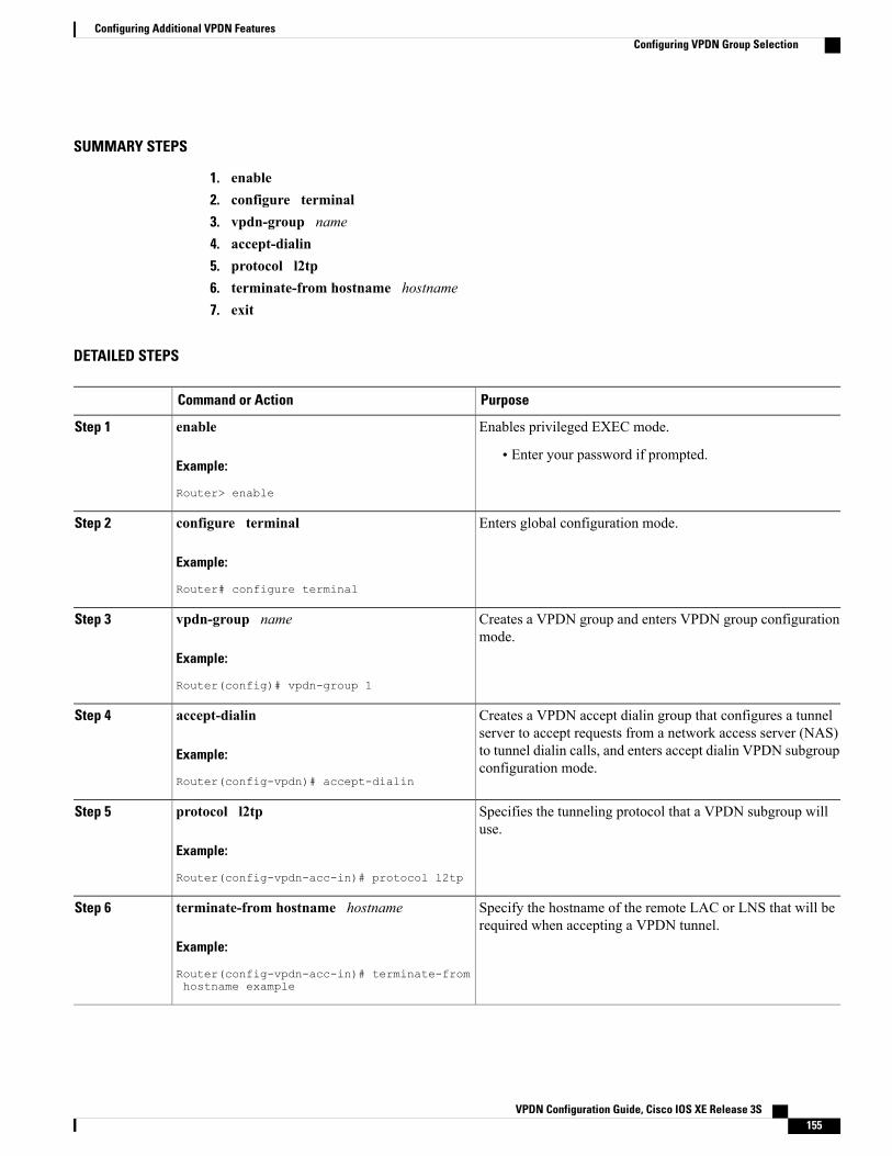
SUMMARY STEPS
1. enable2. configure terminal3. vpdn-group name4. accept-dialin5. protocol l2tp6. terminate-from hostname hostname7. exit
DETAILED STEPS
PurposeCommand or Action
Enables privileged EXEC mode.enableStep 1
Example:
Router> enable
• Enter your password if prompted.
Enters global configuration mode.configure terminal
Example:
Router# configure terminal
Step 2
Creates a VPDN group and enters VPDN group configurationmode.
vpdn-group name
Example:
Router(config)# vpdn-group 1
Step 3
Creates a VPDN accept dialin group that configures a tunnelserver to accept requests from a network access server (NAS)
accept-dialin
Example:
Router(config-vpdn)# accept-dialin
Step 4
to tunnel dialin calls, and enters accept dialin VPDN subgroupconfiguration mode.
Specifies the tunneling protocol that a VPDN subgroup willuse.
protocol l2tp
Example:
Router(config-vpdn-acc-in)# protocol l2tp
Step 5
Specify the hostname of the remote LAC or LNS that will berequired when accepting a VPDN tunnel.
terminate-from hostname hostname
Example:
Router(config-vpdn-acc-in)# terminate-fromhostname example
Step 6
VPDN Configuration Guide, Cisco IOS XE Release 3S 155
Configuring Additional VPDN FeaturesConfiguring VPDN Group Selection

PurposeCommand or Action
Exits VPDN accept dialin group configuration mode.exit
Example:
Router(config-vpdn-acc-in)# exit
Step 7
Configuring VPDN Group Selection Based on a Source IP Address
SUMMARY STEPS
1. enable2. configure terminal3. vpdn-group name4. accept-dialin5. protocol l2tp6. source-ip ip-address7. exit
DETAILED STEPS
PurposeCommand or Action
Enables privileged EXEC mode.enableStep 1
Example:
Router> enable
• Enter your password if prompted.
Enters global configuration mode.configure terminal
Example:
Router# configure terminal
Step 2
Creates a VPDN group and enters VPDN group configurationmode.
vpdn-group name
Example:
Router(config)# vpdn-group 1
Step 3
VPDN Configuration Guide, Cisco IOS XE Release 3S156
Configuring Additional VPDN FeaturesConfiguring VPDN Group Selection

PurposeCommand or Action
Creates a VPDN accept dialin group that configures a tunnelserver to accept requests from a network access server (NAS)
accept-dialin
Example:
Router(config-vpdn)# accept dialin
Step 4
to tunnel dialin calls, and enters accept dial-in VPDN subgroupconfiguration mode.
Specifies the tunneling protocol that a VPDN subgroup will use.protocol l2tp
Example:
Router(config-vpdn-acc-in)# protocol l2tp
Step 5
Specifies a source IP addresses to which to map the destinationIP addresses in subscriber traffic.
source-ip ip-address
Example:
Router(config-vpdn-acc-in)# source-ip10.10.10.1
Step 6
Exits a VPDN accept dialin group configuration mode.exit
Example:
Router(config-vpdn-acc-in)# exit
Step 7
Configuring VPDN Group Selection Based on VRF
SUMMARY STEPS
1. enable2. configure terminal3. vpdn-group name4. accept-dialin5. protocol l2tp6. vpn vrf vrf-name7. exit
DETAILED STEPS
PurposeCommand or Action
Enables privileged EXEC mode.enableStep 1
VPDN Configuration Guide, Cisco IOS XE Release 3S 157
Configuring Additional VPDN FeaturesConfiguring VPDN Group Selection

PurposeCommand or Action
Example:
Router> enable
• Enter your password if prompted.
Enters global configuration mode.configure terminal
Example:
Router# configure terminal
Step 2
Creates a VPDNgroup and enters VPDNgroup configurationmode.vpdn-group name
Example:
Router(config)# vpdn-group 1
Step 3
Creates a VPDN accept dialin group that configures a tunnel serverto accept requests from a network access server (NAS) to tunnel
accept-dialin
Example:
Router(config-vpdn)# accept dialin
Step 4
dialin calls, and enters accept dial-in VPDN subgroup configurationmode.
Specifies the tunneling protocol that a VPDN subgroup will use.protocol l2tp
Example:
Router(config-vpdn-acc-in)# protocol l2tp
Step 5
Specifies that the source and destination IP addresses of a givenVPDN group belong to a specified Virtual Private Network (VPN)routing and VRF instance.
vpn vrf vrf-name
Example:
Router(config-vpdn-acc-in)# vpn vrf myvrf
Step 6
• vrf vrf-name --Specifies the VRF instance by the VRF name.
Exits accept dialin VPDN subgroup mode.exit
Example:
Router(config)# exit
Step 7
VPDN Configuration Guide, Cisco IOS XE Release 3S158
Configuring Additional VPDN FeaturesConfiguring VPDN Group Selection

Displaying VPDN Group Selections
SUMMARY STEPS
1. enable2. show vpdn group-select3. exit
DETAILED STEPS
PurposeCommand or Action
Enables privileged EXEC mode.enableStep 1
Example:
Router> enable
• Enter your password if prompted.
Displays the information for the selected VPDN group.show vpdn group-select
Example:
Router> show vpdn group-select
Step 2
Exits global configuration mode.exit
Example:
Router> exit
Step 3
Configuring QoS Packet Classifications for VPDNsDepending on the VPDN deployment, instead of using the default setting you can choose to configure yourVPDN network to preserve QoS end to end by copying the contents of the ToS byte from the IP header to theLayer 2 header, or to manually configure custom packet classifications for the VPDN network.
QoS configurations are generally required only on the tunnel server, the device that must manage and prioritizelarge volumes of outbound traffic.
Perform this task if you choose to preserve end-to-end QoS:
Perform either or both of these tasks to manually configure custom packet classifications for your VPDNdeployment:
VPDN Configuration Guide, Cisco IOS XE Release 3S 159
Configuring Additional VPDN FeaturesDisplaying VPDN Group Selections

Configuring Preservation of QoS Classifications in the ToS ByteWhen Layer 2 packets are created the ToS byte value is set to zero by default, indicating normal service. Thissetting ignores the values of the ToS byte of the encapsulated IP packets that are being tunneled. The tunnelserver can be configured to copy the contents of the ToS field of the inner IP packets to the ToS byte of theLayer 2 header. Copying the ToS field from the IP header to the Layer 2 header preserves end-to-end QoSfor tunneled packets.
Perform this task to configure a tunnel server to copy the ToS byte from the IP packet to the Layer 2 header.
Before You Begin
A VPDN deployment must be configured.
Note • The tunneled link must carry IP packets for the ToS field to be preserved.
• Proxy PPP dial-in is not supported.
• The tunneled link must carry IP for the ToS field to be preserved. The encapsulated payload ofMultilink PPP (MLP) connections is not IP, therefore this task has no effect when MLP is tunneled.
SUMMARY STEPS
1. enable2. configure terminal3. vpdn-group name4. ip tos reflect
DETAILED STEPS
PurposeCommand or Action
Enables privileged EXEC mode.enableStep 1
Example:
Router> enable
• Enter your password if prompted.
Enters global configuration mode.configure terminal
Example:
Router# configure terminal
Step 2
Creates aVPDNgroup and enters VPDNgroup configurationmode.
vpdn-group name
Example:
Router(config)# vpdn-group 1
Step 3
VPDN Configuration Guide, Cisco IOS XE Release 3S160
Configuring Additional VPDN FeaturesConfiguring QoS Packet Classifications for VPDNs

PurposeCommand or Action
Configures a VPDN group to copy the ToS byte value of IPpacket to the Layer 2 header.
ip tos reflect
Example:
Router(config-vpdn)# ip tos reflect
Step 4
Manually Configuring the IP Precedence for VPDNsIP precedence bits of the ToS byte can be manually configured to set a CoS for Layer 2 packets. If you chooseto manually configure a specific IP precedence value for Layer 2 packets, QoS will not be preserved end toend across the tunnel.
Perform this task on the tunnel server to manually configure a CoS for Layer 2 packets.
Before You Begin
A VPDN deployment must be configured.
Manual configuration of an IP precedence value will override the configuration of the ip tos reflectcommand.
Note
SUMMARY STEPS
1. enable2. configure terminal3. vpdn-group name4. ip precedence [number | name]
DETAILED STEPS
PurposeCommand or Action
Enables privileged EXEC mode.enableStep 1
Example:
Router> enable
• Enter your password if prompted.
Enters global configuration mode.configure terminal
Example:
Router# configure terminal
Step 2
VPDN Configuration Guide, Cisco IOS XE Release 3S 161
Configuring Additional VPDN FeaturesConfiguring QoS Packet Classifications for VPDNs

PurposeCommand or Action
Creates a VPDN group and enters VPDN groupconfiguration mode.
vpdn-group name
Example:
Router(config)# vpdn-group 1
Step 3
Sets the precedence value in the VPDN Layer 2encapsulation header.
ip precedence [number | name]
Example:
Router(config-vpdn)# ip precedence 1
Step 4
Manually Configuring the ToS for VPDN SessionsThe ToS bits can be manually configured to mark the ToS of a packet. If you choose to manually configurea specific ToS value for Layer 2 packets, QoS will not be preserved end-to-end across the tunnel.
Perform this task on the tunnel server to manually configure a CoS for Layer 2 packets.
Before You Begin
A VPDN deployment must be configured.
Manual configuration of a ToS value will override the configuration of the ip tos reflect command.Note
SUMMARY STEPS
1. enable2. configure terminal3. vpdn-group name4. ip tos {tos-bit-value |max-reliability |max-throughput |min-delay |min-monetary-cost | normal}
DETAILED STEPS
PurposeCommand or Action
Enables privileged EXEC mode.enableStep 1
Example:
Router> enable
• Enter your password if prompted.
VPDN Configuration Guide, Cisco IOS XE Release 3S162
Configuring Additional VPDN FeaturesConfiguring QoS Packet Classifications for VPDNs

PurposeCommand or Action
Enters global configuration mode.configure terminal
Example:
Router# configure terminal
Step 2
Creates a VPDN group and enters VPDN groupconfiguration mode.
vpdn-group name
Example:
Router(config)# vpdn-group 1
Step 3
Sets the ToS bits in the VPDN Layer 2 encapsulationheader.
ip tos {tos-bit-value |max-reliability |max-throughput |min-delay |min-monetary-cost | normal}
Example:
Router(config-vpdn)# ip tos 9
Step 4
Configuration Examples for Additional VPDN Features
Example Configuring a Global VPDN TemplateThe following example configures two VPDN parameters in the unnamed global VPDN template:
vpdn-templatelocal name host43ip tos reflect
Example Configuring a Named VPDN TemplateThe following example configures twoVPDN parameters in a VPDN template named l2tp. The namedVPDNtemplate is associated with the VPDN group named l2tp_tunnels.
vpdn-template l2tpl2tp tunnel busy timeout 65l2tp tunnel password tunnel4me!vpdn-group l2tp_tunnelssource vpdn-template l2tp_tunnels
VPDN Configuration Guide, Cisco IOS XE Release 3S 163
Configuring Additional VPDN FeaturesConfiguration Examples for Additional VPDN Features

Example Disassociating a VPDN Group from the VPDN TemplateThe following example disassociates the VPDN group named l2tp from the VPDN template. The systemdefault settings will be used for all VPDN parameters that are not specified in the VPDN group configuration.
vpdn-group l2tpno source vpdn-template
Example Configuring a Global VPDN Source IP AddressThe following example configures a global source IP address. This source IP address will be used for alltunnels established on the router unless a specific source IP address is configured for a VPDN group.
vpdn source-ip 10.1.1.1
Example Configuring a Source IP Address for a VPDN GroupThe following example configures a source IP address for tunnels associated with the VPDN group namedtunneling. This source IP address will override any configured global source IP address for tunnels associatedwith this VPDN group.
vpdn-group tunnelingsource-ip 10.1.1.2
Example Configuring VRF-Aware VPDN Tunnels LocallyThe following example configures a multihop tunnel switch to connect a NAS to a remote tunnel server withina VRF:
NAS
interface loopback 0ip address 172.16.45.6 255.255.255.255!vpdn enablevpdn-group group1request-dialinprotocol l2tpdomain cisco.com!initiate-to 10.10.104.9local name nas32source-ip 172.16.45.6l2tp tunnel password secret1
Multihop Tunnel Switch
ip vrf cisco-vrfvpn id A1:3F6C!interface loopback 0ip address 10.10.104.22 255.255.255.255!
VPDN Configuration Guide, Cisco IOS XE Release 3S164
Configuring Additional VPDN FeaturesExample Disassociating a VPDN Group from the VPDN Template

interface loopback 40ip vrf forwarding cisco-vrfip address 172.16.40.241 255.255.255.255!vpdn enablevpdn multihop!vpdn-group mhopinaccept-dialinprotocol l2tpvirtual-template 4!terminate-from hostname nas32source-ip 10.10.104.9l2tp tunnel password secret1!vpdn-group mhopoutrequest-dialinprotocol l2tpdomain cisco.com!vpn vrf cisco-vrfinitiate-to ip 172.16.45.6source-ip 172.16.40.241local name multihop-tsw25l2tp tunnel password secret2
Tunnel Server
interface loopback 0ip address 172.16.45.6 255.255.255.255!vpdn enablevpdn-group ciscoaccept-dialinprotocol l2tpvirtual-template 1!terminate-from hostname multihop-tsw25source-ip 172.16.45.6local name ts-12l2tp tunnel password secret2
Examples Configuring VRF-Aware VPDN Tunnels on the Remote RADIUS AAAServer
The following examples configure VRF-aware VPDN tunnels for a service provider network. The AAARADIUS server user profile defines VPDN tunnel attributes, which can propagate to multiple NASs or tunnelswitches.
RADIUS User Profile--VRF Name
The following example specifies that the source and destination IP addresses belong to the VPN namedvpn-first:
cisco.com Password = "secret"Service-Type = Outbound-User,cisco-avpair = "vpdn:tunnel-id=LAC",cisco-avpair = "vpdn:tunnel-type=l2tp",cisco-avpair = "vpdn:ip-addresses=10.0.0.1",cisco-avpair = "vpdn:source-ip=10.0.0.9",cisco-avpair = "vpdn:vpn-vrf=vpn-first"cisco-avpair = "vpdn:l2tp-tunnel-password=supersecret"
VPDN Configuration Guide, Cisco IOS XE Release 3S 165
Configuring Additional VPDN FeaturesExamples Configuring VRF-Aware VPDN Tunnels on the Remote RADIUS AAA Server

RADIUS User Profile--VRF ID
The following example specifies that the source and destination IP addresses belong to the VPN with the IDA1:3F6C:
cisco.com Password = "secret"Service-Type = Outbound-User,cisco-avpair = "vpdn:tunnel-id=LAC",cisco-avpair = "vpdn:tunnel-type=l2tp",cisco-avpair = "vpdn:ip-addresses=10.0.0.1",cisco-avpair = "vpdn:source-ip=10.0.0.9",cisco-avpair = "vpdn:vpn-id=A1:3F6C"cisco-avpair = "vpdn:l2tp-tunnel-password=supersecret"
Example Manually Configuring the IP MTU for VPDN DeploymentsThe following example manually configures an IP MTU of 1460 bytes for all tunnels that use thevirtual-template named 1:
interface virtual-template 1ip mtu 1460
Example Enabling Automatic Adjustment of the IP MTU for VPDN DeploymentsThe following example configures tunnels associated with the VPDN group named tunneler to automaticallyadjust the IP MTU based on the MTU of the egress interface of the device:
vpdn-group tunnelerip mtu adjust
Example Manually Configuring the Advertised TCP MSSThe following example manually configures a TCP MSS of 1420 bytes for all tunnels that use the virtualtemplate named 2:
interface virtual-template 2ip tcp adjust-mss 1420
Example Configuring MRU AdvertisingThe following example manually configures anMTU of 1460 bytes for all tunnels that use the virtual templatenamed 3. The VPDN group named mytunnels is configured to perform LCP renegotiation because it usesproxy LCP.
interface virtual-template 3mtu 1460!vpdn-group mytunnelslcp renegotiation always
VPDN Configuration Guide, Cisco IOS XE Release 3S166
Configuring Additional VPDN FeaturesExample Manually Configuring the IP MTU for VPDN Deployments

Example Configuring Preservation of QoS Classifications in the ToS ByteThe following example configures preservation of the IP ToS field for an existing VPDN group named out1:
vpdn-group out1ip tos reflect
Example Manually Configuring the IP Precedence for VPDNsThe following example manually configures an IP precedence value for an existing VPDN group named out2:
vpdn-group out2ip precedence priority
Example Manually Configuring the ToS for VPDN SessionsThe following example manually configures a ToS classification for an existing VPDN group named out3:
vpdn-group out3ip tos 9
Configuration Examples for VPDN Group Selection
Example Configuring VPDN Group Selection Based on HostnameThe following example configuration shows a LAC-1 building a VPDN tunnel to an LNS, and the LNSwouldterminating the session on vpdn-group 1:
Router> enableRouter# configure terminalRouter(config)# vpdn-group 1Router(config-vpdn)# accept-dialinRouter(config-vpdn-acc-in)# protocol l2tpRouter(config-vpdn-acc-in)# terminate-from hostname LAC-1
Example Configuring VPDN Group Selection Based on an IP AddressThe following example configuration shows a LAC-1/LAC-2 building a VPDN tunnel to IP address 10.10.10.1,and the LNS terminating the session on vpdn-group 1. If an LAC-1/LAC-2 builds a VPDN tunnel to IP address10.10.10.2, the LNS terminates the session on vpdn-group 2. Any source IP address match is optional.
Router> enableRouter# configure terminalRouter(config)# vpdn-group 1Router(config-vpdn)# accept-dialinRouter(config-vpdn-acc-in)# protocol l2tpRouter(config-vpdn-acc-in)# source-ip 10.10.10.1Router(config-vpdn-acc-in)# exitRouter(config-vpdn)# exitRouter(config)# vpdn-group 2
VPDN Configuration Guide, Cisco IOS XE Release 3S 167
Configuring Additional VPDN FeaturesExample Configuring Preservation of QoS Classifications in the ToS Byte
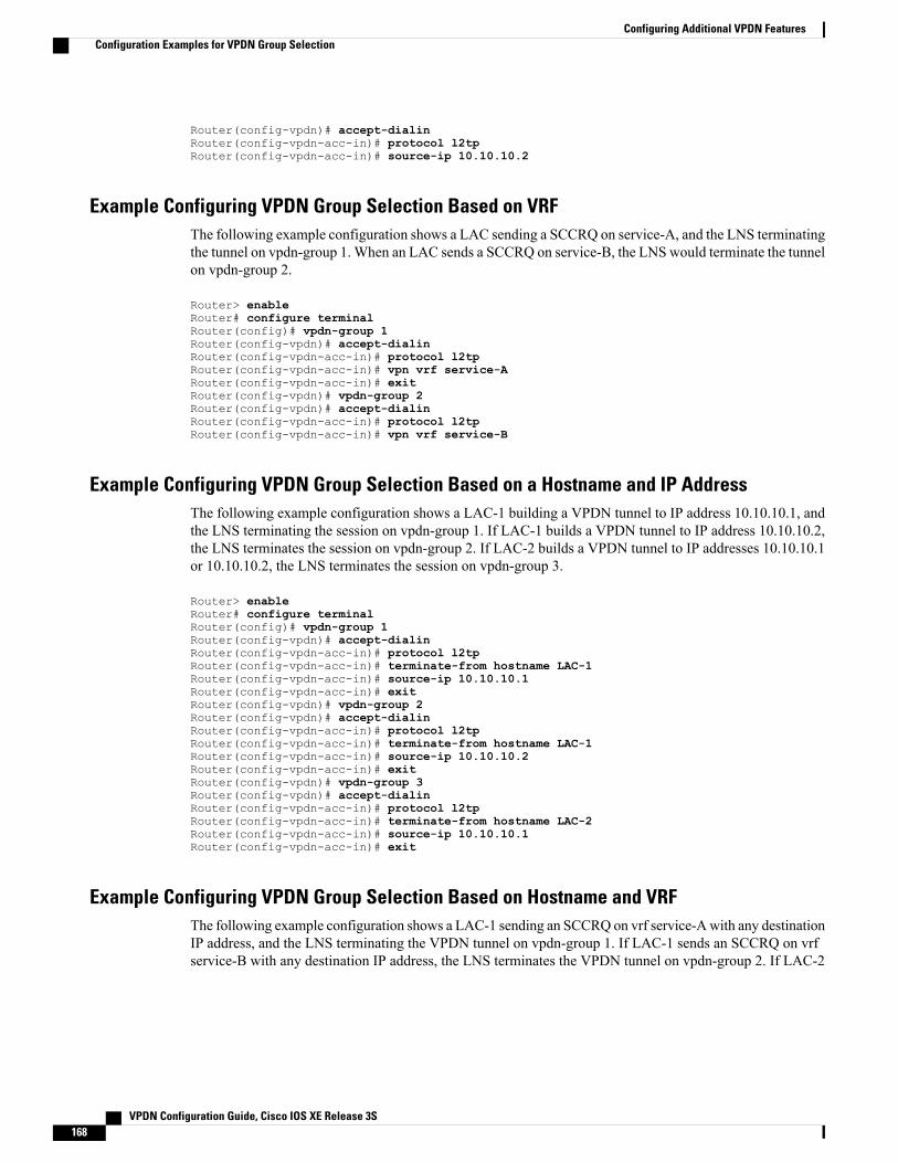
Router(config-vpdn)# accept-dialinRouter(config-vpdn-acc-in)# protocol l2tpRouter(config-vpdn-acc-in)# source-ip 10.10.10.2
Example Configuring VPDN Group Selection Based on VRFThe following example configuration shows a LAC sending a SCCRQ on service-A, and the LNS terminatingthe tunnel on vpdn-group 1. When an LAC sends a SCCRQ on service-B, the LNS would terminate the tunnelon vpdn-group 2.
Router> enableRouter# configure terminalRouter(config)# vpdn-group 1Router(config-vpdn)# accept-dialinRouter(config-vpdn-acc-in)# protocol l2tpRouter(config-vpdn-acc-in)# vpn vrf service-ARouter(config-vpdn-acc-in)# exitRouter(config-vpdn)# vpdn-group 2Router(config-vpdn)# accept-dialinRouter(config-vpdn-acc-in)# protocol l2tpRouter(config-vpdn-acc-in)# vpn vrf service-B
Example Configuring VPDN Group Selection Based on a Hostname and IP AddressThe following example configuration shows a LAC-1 building a VPDN tunnel to IP address 10.10.10.1, andthe LNS terminating the session on vpdn-group 1. If LAC-1 builds a VPDN tunnel to IP address 10.10.10.2,the LNS terminates the session on vpdn-group 2. If LAC-2 builds a VPDN tunnel to IP addresses 10.10.10.1or 10.10.10.2, the LNS terminates the session on vpdn-group 3.
Router> enableRouter# configure terminalRouter(config)# vpdn-group 1Router(config-vpdn)# accept-dialinRouter(config-vpdn-acc-in)# protocol l2tpRouter(config-vpdn-acc-in)# terminate-from hostname LAC-1Router(config-vpdn-acc-in)# source-ip 10.10.10.1Router(config-vpdn-acc-in)# exitRouter(config-vpdn)# vpdn-group 2Router(config-vpdn)# accept-dialinRouter(config-vpdn-acc-in)# protocol l2tpRouter(config-vpdn-acc-in)# terminate-from hostname LAC-1Router(config-vpdn-acc-in)# source-ip 10.10.10.2Router(config-vpdn-acc-in)# exitRouter(config-vpdn)# vpdn-group 3Router(config-vpdn)# accept-dialinRouter(config-vpdn-acc-in)# protocol l2tpRouter(config-vpdn-acc-in)# terminate-from hostname LAC-2Router(config-vpdn-acc-in)# source-ip 10.10.10.1Router(config-vpdn-acc-in)# exit
Example Configuring VPDN Group Selection Based on Hostname and VRFThe following example configuration shows a LAC-1 sending an SCCRQ on vrf service-Awith any destinationIP address, and the LNS terminating the VPDN tunnel on vpdn-group 1. If LAC-1 sends an SCCRQ on vrfservice-B with any destination IP address, the LNS terminates the VPDN tunnel on vpdn-group 2. If LAC-2
VPDN Configuration Guide, Cisco IOS XE Release 3S168
Configuring Additional VPDN FeaturesConfiguration Examples for VPDN Group Selection

sends an SCCRQ on vrf service-B with any destination IP address, the LNS terminates the VPDN tunnel onvpdn-group 3.
Router> enableRouter# configure terminalRouter(config)# vpdn-group 1Router(config-vpdn)# accept-dialinRouter(config-vpdn-acc-in)# protocol l2tpRouter(config-vpdn-acc-in)# vpn vrf service-ARouter(config-vpdn-acc-in)# terminate-from hostname LAC-1Router(config-vpdn-acc-in)# exitRouter(config-vpdn)# vpdn-group 2Router(config-vpdn)# accept-dialinRouter(config-vpdn-acc-in)# protocol l2tpRouter(config-vpdn-acc-in)# vpn vrf service-BRouter(config-vpdn-acc-in)# terminate-from hostname LAC-1Router(config-vpdn-acc-in)# exitRouter(config-vpdn)# vpdn-group 3Router(config-vpdn)# accept-dialinRouter(config-vpdn-acc-in)# protocol l2tpRouter(config-vpdn-acc-in)# vpn vrf service-BRouter(config-vpdn-acc-in)# terminate-from hostname LAC-2Router(config-vpdn-acc-in)# exit
Example Configuring VPDN Group Selection Based on an IP Address and VRFThe following example configuration shows a LAC-1/LAC-2 sending an SCCRQon vrf service-A to destinationIP address 10.10.10.1, and the LNS terminating the VPDN tunnel on vpdn-group 1. If LAC-1/LAC-2 sendsan SCCRQ on vrf service-A to destination IP address 10.10.10.2, the LNS terminates the VPDN tunnel onvpdn-group 2.
Router> enableRouter# configure terminalRouter(config)# vpdn-group 1Router(config-vpdn)# accept-dialinRouter(config-vpdn-acc-in)# protocol l2tpRouter(config-vpdn-acc-in)# vpn vrf service-ARouter(config-vpdn-acc-in)# source-ip 10.10.10.1Router(config-vpdn-acc-in)# exitRouter(config-vpdn)# exitRouter(config)# vpdn-group 2Router(config-vpdn)# accept-dialinRouter(config-vpdn-acc-in)# protocol l2tpRouter(config-vpdn-acc-in)# vpn vrf service-ARouter(config-vpdn-acc-in)# source-ip 10.10.10.2Router(config-vpdn-acc-in)# exit
Example Configuring VPDN Group Selection Based on Hostname VRF and IP AddressThe following example configuration shows a LAC-1 sending an SCCRQ on vrf service-A to destination IPaddress 10.10.10.1, and the LNS terminating the VPDN tunnel on vpdn-group 1. If LAC-1 sends an SCCRQon vrf service-B to destination IP address 10.10.10.1, the LNS terminates the VPDN tunnel on vpdn-group2.
Router> enableRouter# configure terminalRouter(config)# vpdn-group 1Router(config-vpdn)# accept-dialinRouter(config-vpdn-acc-in)# protocol l2tpRouter(config-vpdn-acc-in)# vpn vrf service-ARouter(config-vpdn-acc-in)# terminate-from hostname LAC-1
VPDN Configuration Guide, Cisco IOS XE Release 3S 169
Configuring Additional VPDN FeaturesConfiguration Examples for VPDN Group Selection

Router(config-vpdn-acc-in)# source-ip 10.10.10.1Router(config-vpdn-acc-in)# exitRouter(config-vpdn)# exitRouter(config)# vpdn-group 2Router(config-vpdn)# accept-dialinRouter(config-vpdn-acc-in)# protocol l2tpRouter(config-vpdn-acc-in)# vpn vrf service-BRouter(config-vpdn-acc-in)# terminate-from hostname LAC-1Router(config-vpdn-acc-in)# source-ip 10.10.10.1Router(config-vpdn-acc-in)# exit
Examples Displaying VPDN Group SelectionThe VPDN Group Selection feature allows you to display VPDN group information based in a source IPaddress, a hostname, or VFR.
For examples purposes, the following configuration will be used for the display examples.
Router> enableRouter# configure terminalRouter(config)# vpdn-group vgdefaultRouter(config-vpdn)# accept-dialinRouter(config-vpdn-acc-in)# protocol l2tpRouter(config-vpdn-acc-in)# virtual-template 20Router(config-vpdn-acc-in)# local name lnsRouter(config-vpdn)# l2tp tunnel password 0 exampleRouter(config-vpdn)# exitRouter(config)# vpdn-group vg-ip2Router(config-vpdn)# accept-dialinRouter(config-vpdn-acc-in)# protocol l2tpRouter(config-vpdn-acc-in)# virtual-template 5Router(config-vpdn-acc-in)# source-ip 10.1.1.2Router(config-vpdn)# local name lnsRouter(config-vpdn)# l2tp tunnel password 0 exampleRouter(config-vpdn)# exitRouter(config)# vpdn-group vg-ip3Router(config-vpdn)# accept-dialinRouter(config-vpdn-acc-in)# protocol l2tpRouter(config-vpdn-acc-in)# virtual-template 5Router(config-vpdn-acc-in)# source-ip 10.1.1.3Router(config-vpdn)# local name lnsRouter(config-vpdn)# l2tp tunnel password 0example
Router(config-vpdn)# exitRouter(config)# vpdn-group vg-ltsRouter(config-vpdn)# accept-dialinRouter(config-vpdn-acc-in) # protocol l2tpRouter(config-vpdn-acc-in)# virtual-template 5Router(config-vpdn-acc-in)# terminate host ltsRouter(config-vpdn)# local name lnsRouter(config-vpdn)# l2tp tunnel password 0 exampleRouter(config-vpdn)# exitRouter(config)# vpdn-group vg-lts1Router(config-vpdn)# accept-dialinRouter(config-vpdn-acc-in)# protocol l2tpRouter(config-vpdn-acc-in)# virtual-template 5Router(config-vpdn-acc-in)# terminate host lts1Router(config-vpdn)# local name lnsRouter(config-vpdn)# l2tp tunnel password 0 exampleRouter(config-vpdn)# exitRouter(config)# vpdn-group vg-lts1-ip2Router(config-vpdn)# accept-dialinRouter(config-vpdn-acc-in)# protocol l2tpRouter(config-vpdn-acc-in)# virtual-template 5Router(config-vpdn-acc-in)# terminate host lts1
VPDN Configuration Guide, Cisco IOS XE Release 3S170
Configuring Additional VPDN FeaturesExamples Displaying VPDN Group Selection

Router(config-vpdn)# source-ip 10.1.1.2Router(config-vpdn)# local name lnsRouter(config-vpdn)# l2tp tunnel password 0 exampleRouter(config-vpdn)# exitRouter(config)# end
Examples Displaying VPDN Group-Select SummariesThe following example shows VPDN group-select information for the example configuration.
Router# show vpdn group-select summaryVPDN Group Vrf Remote Name Source-IP Protocol Directionvg-ip2 10.1.1.2 l2tp accept-dialinvg-ip3 10.1.1.3 l2tp accept-dialinvg-lts lts 0.0.0.0 l2tp accept-dialinvg-lts1 lts1 0.0.0.0 l2tp accept-dialinvg-lts1-ip2 vfr101 lts1 10.1.1.2 l2tp accept-dialinvgdefault 0.0.0.0 l2tp accept-dialinThe following is sample output from the show vpdn group-select keys command for a host with the namelac-1 and an IP address of 10.0.0.1:
Router# show vpdn group-select keys vrf vrf-blue hostname lac-1 source-ip 10.0.0.1VPDN Group Vrf Hostname Source Ipvg1 vrf-blue lac-1 10.0.0.1The following shows an example output for the show vpdn group-select default command for the exampleconfiguration:
Router# show vpdn group-select defaultDefault VPDN Group Protocolvgdefault l2tpNone pptpThe following is sample output from the show vpdn group-select keyscommand for a host with the namelac-5 and an IP address of 10.1.1.0, and VRF name vrf-red:
Router# show vpdn group-select keys vrf vrf-red hostname lac-5 source-ip 10.1.1.0VPDN Group Vrf Hostname Source IpVg2 vrf-red lac-5 10.1.1.0
Where to Go NextYou can perform any of the relevant optional tasks in the VPDN Tunnel Management module.
Additional ReferencesRelated Documents
Document TitleRelated Topic
Cisco IOS Master Commands List, All ReleasesCisco IOS commands
VPDN Technology OverviewVPDN technology overview
VPDN Configuration Guide, Cisco IOS XE Release 3S 171
Configuring Additional VPDN FeaturesWhere to Go Next
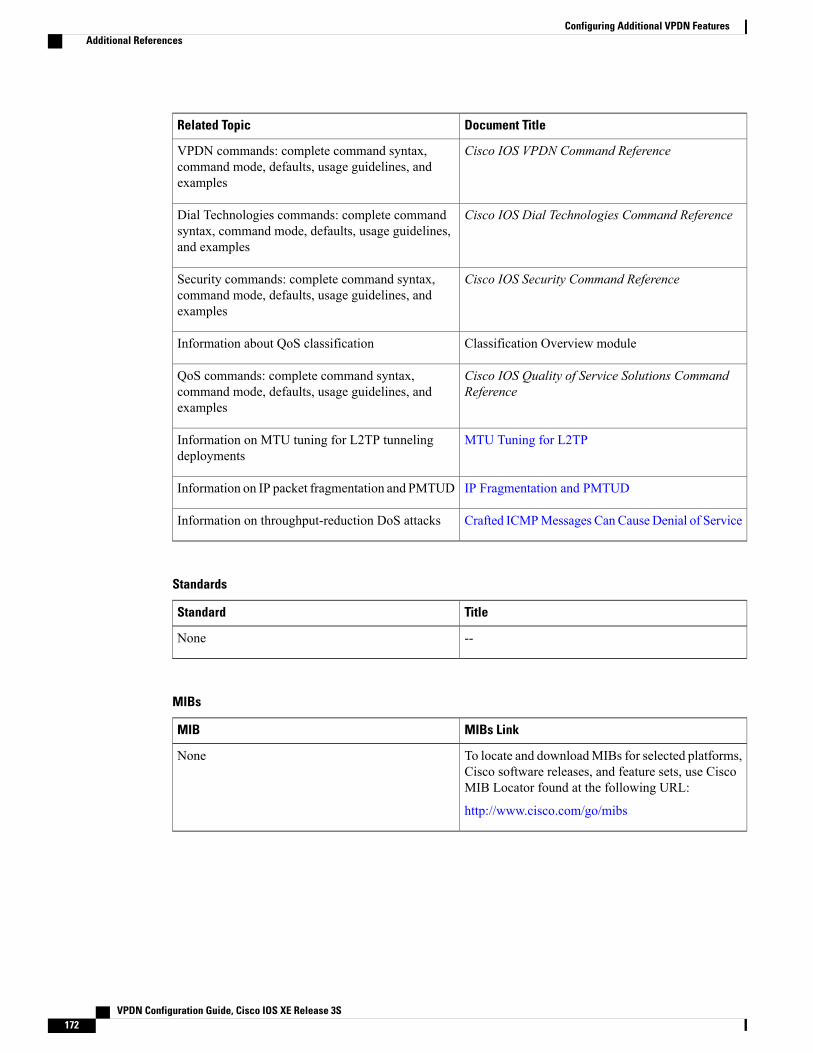
Document TitleRelated Topic
Cisco IOS VPDN Command ReferenceVPDN commands: complete command syntax,command mode, defaults, usage guidelines, andexamples
Cisco IOS Dial Technologies Command ReferenceDial Technologies commands: complete commandsyntax, command mode, defaults, usage guidelines,and examples
Cisco IOS Security Command ReferenceSecurity commands: complete command syntax,command mode, defaults, usage guidelines, andexamples
Classification Overview moduleInformation about QoS classification
Cisco IOS Quality of Service Solutions CommandReference
QoS commands: complete command syntax,command mode, defaults, usage guidelines, andexamples
MTU Tuning for L2TPInformation on MTU tuning for L2TP tunnelingdeployments
IP Fragmentation and PMTUDInformation on IP packet fragmentation and PMTUD
Crafted ICMPMessages Can Cause Denial of ServiceInformation on throughput-reduction DoS attacks
Standards
TitleStandard
--None
MIBs
MIBs LinkMIB
To locate and downloadMIBs for selected platforms,Cisco software releases, and feature sets, use CiscoMIB Locator found at the following URL:
http://www.cisco.com/go/mibs
None
VPDN Configuration Guide, Cisco IOS XE Release 3S172
Configuring Additional VPDN FeaturesAdditional References

RFCs
TitleRFC
Path MTU DiscoveryRFC 1191
Layer Two Tunneling Protocol (L2TP)RFC 2661
TCP Problems with Path MTU DiscoveryRFC 2923
Technical Assistance
LinkDescription
http://www.cisco.com/cisco/web/support/index.htmlThe Cisco Support and Documentation websiteprovides online resources to download documentation,software, and tools. Use these resources to install andconfigure the software and to troubleshoot and resolvetechnical issues with Cisco products and technologies.Access to most tools on the Cisco Support andDocumentation website requires a Cisco.com user IDand password.
Feature Information for Additional VPDN FeaturesThe following table provides release information about the feature or features described in this module. Thistable lists only the software release that introduced support for a given feature in a given software releasetrain. Unless noted otherwise, subsequent releases of that software release train also support that feature.
Use Cisco Feature Navigator to find information about platform support and Cisco software image support.To access Cisco Feature Navigator, go to www.cisco.com/go/cfn. An account on Cisco.com is not required.
Table 12: Feature Information for Configuring Additional VPDN Features
Feature Configuration InformationSoftware ReleasesFeature Name
This feature introduces the abilityto configure global default valuesfor VPDN group parameters in aVPDN template. These globaldefault values are applied to allVPDN groups, unless specificvalues are configured for individualVPDN groups.
The following commands wereintroduced by this feature: sourcevpdn-template andvpdn-template.
Cisco IOS XE Release 2.1VPDN Default Group Template
VPDN Configuration Guide, Cisco IOS XE Release 3S 173
Configuring Additional VPDN FeaturesFeature Information for Additional VPDN Features

Feature Configuration InformationSoftware ReleasesFeature Name
This feature configures customized,multiple VPDN tunnels withdifferent VPDN groupconfigurations between a LAC andan LNS.
The following command wereintroduced by this feature: showvpdn group-selectand show vpdngroup-select keys.
Cisco IOS XE Release 2.1VPDN Group Selection
This feature introduces support tomake the following RADIUSattributes VRF aware: attribute 22(Framed-Route), a combination ofattribute 8 (Framed-IP-Address)and attribute 9(Framed-IP-Netmask), and theCisco VSA route command. Thus,static IP routes can be applied to aparticular VRF routing table ratherthan the global routing table.
Cisco IOS XE Release 2.1VPN Routing Forwarding (VRF)Framed Route (Pool) Assignmentvia PPP
This feature enhances the supportof VPDN tunnels by allowingVPDN tunnels to start outside anMPLS VPN and terminate withinthe MPLS VPN.
The following command wasintroduced by this feature: vpn.
Cisco IOS XE Release 2.2VRF-Aware VPDN Tunnels
VPDN Configuration Guide, Cisco IOS XE Release 3S174
Configuring Additional VPDN FeaturesFeature Information for Additional VPDN Features

C H A P T E R 6VPDN Tunnel Management
This module contains information about managing virtual private dialup network (VPDN) tunnels andmonitoring VPDN events. The tasks documented in this module should be performed only after configuringand deploying a VPDN.
• Finding Feature Information, page 175
• Prerequisites for VPDN Tunnel Management, page 175
• Restrictions for VPDN Tunnel Management, page 176
• Information About VPDN Tunnel Management, page 176
• How to Manage VPDN Tunnels, page 178
• Configuration Examples for VPDN Tunnel Management, page 194
• Additional References, page 198
• Feature Information for VPDN Tunnel Management, page 199
Finding Feature InformationYour software release may not support all the features documented in this module. For the latest caveats andfeature information, see Bug Search Tool and the release notes for your platform and software release. Tofind information about the features documented in this module, and to see a list of the releases in which eachfeature is supported, see the feature information table.
Use Cisco Feature Navigator to find information about platform support and Cisco software image support.To access Cisco Feature Navigator, go to www.cisco.com/go/cfn. An account on Cisco.com is not required.
Prerequisites for VPDN Tunnel ManagementBefore you can perform the tasks in this module, you must configure a VPDN deployment. For an overviewof VPDN deployments, see the VPDN Technology Overview module.
VPDN Configuration Guide, Cisco IOS XE Release 3S 175

Restrictions for VPDN Tunnel ManagementVPDN tunnels using the Layer 2 Forwarding (L2F) protocol or Point-to-Point Tunnel Protocol (PPTP) arenot supported.
Information About VPDN Tunnel Management
Termination of VPDN TunnelsVPDN tunnels can be terminated manually or through a soft shutdown.Manual termination of a VPDN tunnelresults in the immediate shutdown of the specified VPDN tunnel and all sessions within that tunnel, resultingin a sudden disruption of VPDN services. Enabling soft shutdown on a router prevents the establishment ofnew VPDN sessions in all VPDN tunnels that terminate on that router, but does not affect existing sessions.Opting to terminate a VPDN tunnel by enabling soft shutdown prevents the disruption of established sessionsthat occurs when a VPDN tunnel is manually terminated.
VPDN Session LimitsThe number of simultaneous VPDN sessions that can be established on a router can be manually configured,providing network administratorsmore control over the network. VPDN session limits can increase performanceand reduce latency for routers that are otherwise forced to operate at high capacity.
The maximum number of VPDN sessions can be configured globally, at the level of a VPDN group, or forall VPDN groups associated with a particular VPDN template.
The hierarchy for the application of VPDN session limits is as follows:
• Globally configured session limits take precedence over session limits configured for a VPDN groupor in a VPDN template. The total number of sessions on a router cannot exceed a configured globalsession limit.
• Session limits configured for a VPDN template are enforced for all VPDN groups associated with thatVPDN template. The total number of sessions for all of the associated VPDN groups cannot exceed theconfigured VPDN template session limit.
• Session limits configured for a VPDN group are enforced for that VPDN group.
Control Packet Parameters for VPDN TunnelsCertain control packet timers, retry counters, and the advertised control packet receive window size can beconfigured for Layer 2 Transport Protocol (L2TP) or Layer 2 Forwarding (L2F) VPDN tunnels. Adjustmentsto these parameters allow fine-tuning of router performance to suit the particular needs of the VPDNdeployment.
VPDN Configuration Guide, Cisco IOS XE Release 3S176
VPDN Tunnel ManagementRestrictions for VPDN Tunnel Management

L2TP Congestion AvoidanceL2TP congestion avoidance provides packet flow control and congestion avoidance by throttling L2TP controlmessages as described in RFC 2661. Throttling L2TP control message packets prevents input buffer overflowson the peer tunnel endpoint, which can result in dropped sessions.
Before the introduction of L2TP congestion avoidance, the window size used to send packets between thenetwork access server (NAS) and the tunnel server was set to the value advertised by the peer endpoint andwas never changed. Configuring L2TP congestion avoidance allows the L2TP packet window to be dynamicallyresized using a sliding window mechanism. The window size grows larger when packets are deliveredsuccessfully, and is reduced when dropped packets must be retransmitted.
L2TP congestion avoidance is useful in networks with a relatively high rate of calls being placed by eithertunnel endpoint. L2TP congestion avoidance is also useful on highly scalable platforms that support manysimultaneous sessions.
How L2TP Congestion Avoidance WorksTCP/IP and RFC 2661 define two algorithms--slow start and congestion avoidance--used to throttle controlmessage traffic between a NAS and a tunnel server. Slow start and congestion avoidance are two independentalgorithms that work together to control congestion. Slow start and congestion avoidance require that twovariables, a slow start threshold (SSTHRESH) size and a congestion window (CWND) size, be maintainedby the sending device for each connection.
The congestion window defines the number of packets that can be transmitted before the sender must waitfor an acknowledgment from its peer. The size of the congestion window expands and contracts, but can neverexceed the size of the peer device’s advertised receive window.The slow start threshold defines the point at which the sending device switches operation from slow startmode to congestion avoidancemode.When the congestion window size is smaller than the slow start threshold,the device operates in slow start mode. When the congestion window size equals the slow start threshold, thedevice switches to congestion avoidance mode.
When a new connection is established, the sending device initially operates in slow start mode. The congestionwindow size is initialized to one packet, and the slow start threshold is set to the receive window size advertisedby the peer tunnel endpoint (the receiving side).
The sending device begins by transmitting one packet and waiting for it to be acknowledged. When theacknowledgment is received, the congestion window size is incremented from one to two, and two packetscan be sent. When those two packets are each acknowledged, the congestion window is increased to four. Thecongestion window doubles for each complete round trip, resulting in an exponential increase in size.
When the congestion window size reaches the slow start threshold value, the sending device switches overto operate in congestion avoidance mode. Congestion avoidance mode slows down the rate at which thecongestion window size grows. In congestion avoidance mode, for every acknowledgment received thecongestion window increases at the rate of 1 divided by the congestion window size. This results in linear,rather than exponential, growth of the congestion window size.
At some point, the capacity of the peer device will be exceeded and packets will be dropped. This indicatesto the sending device that the congestion window has grown too large.When a retransmission event is detected,the slow start threshold value is reset to half of the current congestion window size, the congestion windowsize is reset to one, and the device switches operation to slow start mode (if it was not already operating inthat mode).
VPDN Configuration Guide, Cisco IOS XE Release 3S 177
VPDN Tunnel ManagementL2TP Congestion Avoidance

VPDN Event LoggingThere are two types of VPDN event logging available, VPDN failure event logging and generic VPDN eventlogging. The logging of VPDN failure events is enabled by default. Generic VPDN event logging is disabledby default, and must be explicitly enabled before generic event messages can be viewed.
How to Manage VPDN Tunnels
Manually Terminating VPDN TunnelsManual termination of a VPDN tunnel results in the immediate shutdown of the specified VPDN tunnel andall sessions within that tunnel, resulting in a sudden disruption of VPDN services. Before manually terminatinga VPDN tunnel, consider performing the task in the Enabling Soft Shutdown of VPDN Tunnels, on page 179instead.
A manually terminated VPDN tunnel can be restarted immediately when a user logs in. Manually terminatingand restarting a VPDN tunnel while VPDN event logging is enabled can provide useful troubleshootinginformation about VPDN session establishment.
Perform this task to manually shut down a specific VPDN tunnel, resulting in the termination of the tunneland all sessions in that tunnel. You can perform this task on these devices:
• The tunnel server
• The NAS when it is functioning as a tunnel endpoint
Note • For client-initiated L2TP tunnels, you can perform this task only on the tunnel server.
• Tunnels using the L2F protocol and PPTP are not supported.
SUMMARY STEPS
1. enable2. clear vpdn tunnel l2tp {all | hostname remote-name [local-name] | id local-id | ip local-ip-address |
ip remote-ip-address}
DETAILED STEPS
PurposeCommand or Action
Enables privileged EXEC mode.enableStep 1
Example:
Router> enable
• Enter your password if prompted.
VPDN Configuration Guide, Cisco IOS XE Release 3S178
VPDN Tunnel ManagementVPDN Event Logging

PurposeCommand or Action
Shuts down a specified tunnel and all sessions withinthe tunnel.
clear vpdn tunnel l2tp {all | hostname remote-name[local-name] | id local-id | ip local-ip-address | ipremote-ip-address}
Step 2
Example:
Router# clear vpdn tunnel l2tp all
Enabling Soft Shutdown of VPDN TunnelsEnabling soft shutdown of VPDN tunnels on a router prevents the establishment of new VPDN sessions inall VPDN tunnels that terminate on that router, but does not affect existing sessions. Opting to terminate aVPDN tunnel by enabling soft shutdown prevents the disruption of established sessions that occurs when aVPDN tunnel is manually terminated. Enabling soft shutdown on a router or access server will affect all ofthe tunnels terminating on that device. There is no way to enable soft shutdown for a specific tunnel. If youwant to shut down a specific tunnel on a device without affecting any other tunnels, see the ManuallyTerminating VPDN Tunnels, on page 178 instead.
When soft shutdown is performed on a NAS, the potential session will be authorized before it is refused. Thisauthorization ensures that accurate accounting records can be kept.
When soft shutdown is performed on a tunnel server, the reason for the session refusal will be returned to theNAS. This information is recorded in the VPDN history failure table.
Enabling soft shutdown of VPDN tunnels does not affect the establishment of Multichassis Multilink PPP(MMP) tunnels.
Note
Perform this task to prevent new sessions from being established in any VPDN tunnel terminating on therouter without disturbing service for existing sessions. You can perform this task on these devices:
• The tunnel server
• The NAS when it is functioning as a tunnel endpoint
Note • For client-initiated L2TP tunnels, you can perform this task only on the tunnel server.
• Enabling soft shutdown of VPDN tunnels will not prevent newMMP sessions from being established.
VPDN Configuration Guide, Cisco IOS XE Release 3S 179
VPDN Tunnel ManagementEnabling Soft Shutdown of VPDN Tunnels

SUMMARY STEPS
1. enable2. configure terminal3. vpdn softshut
DETAILED STEPS
PurposeCommand or Action
Enables privileged EXEC mode.enableStep 1
Example:
Router> enable
• Enter your password if prompted.
Enters global configuration mode.configure terminal
Example:
Router# configure terminal
Step 2
Prevents new sessions from being established on a VPDNtunnel without disturbing existing sessions.
vpdn softshut
Example:
Router(config)# vpdn softshut
Step 3
Verifying the Soft Shutdown of VPDN TunnelsPerform this task to ensure that soft shutdown is working properly.
SUMMARY STEPS
1. Establish a VPDN session by dialing in to the NAS using an allowed username and password.2. enable3. configure terminal4. vpdn softshut5. exit6. show vpdn7. Attempt to establish a new VPDN session by dialing in to the NAS using a second allowed username and
password.8. show vpdn history failure
VPDN Configuration Guide, Cisco IOS XE Release 3S180
VPDN Tunnel ManagementVerifying the Soft Shutdown of VPDN Tunnels

DETAILED STEPS
PurposeCommand or Action
Establish a VPDN session by dialing in to the NASusing an allowed username and password.
Step 1
Enables privileged EXEC mode.enableStep 2
Example:
Router> enable
• Enter your password if prompted.
Enters global configuration mode.configure terminal
Example:
Router# configure terminal
Step 3
Prevents new sessions from being established on a VPDNtunnel without disturbing existing sessions. You can issuethis command on either the NAS or the tunnel server.
vpdn softshut
Example:
Router(config)# vpdn softshut
Step 4
Exits to privileged EXEC mode.exit
Example:
Router(config)# exit
Step 5
Displays information about active L2TP or L2F tunnels andmessage identifiers in a VPDN. Issue this command to verifythat the original session is active:
show vpdn
Example:
Router# show vpdn
Step 6
If soft shutdown has been enabled, a system logging (syslog)message appears on the console of the soft shutdown router.
Attempt to establish a new VPDN session by dialingin to the NAS using a second allowed username andpassword.
Step 7
Displays the content of the history failure table.show vpdn history failure
Example:
Router# show vpdn history failure
Step 8
VPDN Configuration Guide, Cisco IOS XE Release 3S 181
VPDN Tunnel ManagementVerifying the Soft Shutdown of VPDN Tunnels
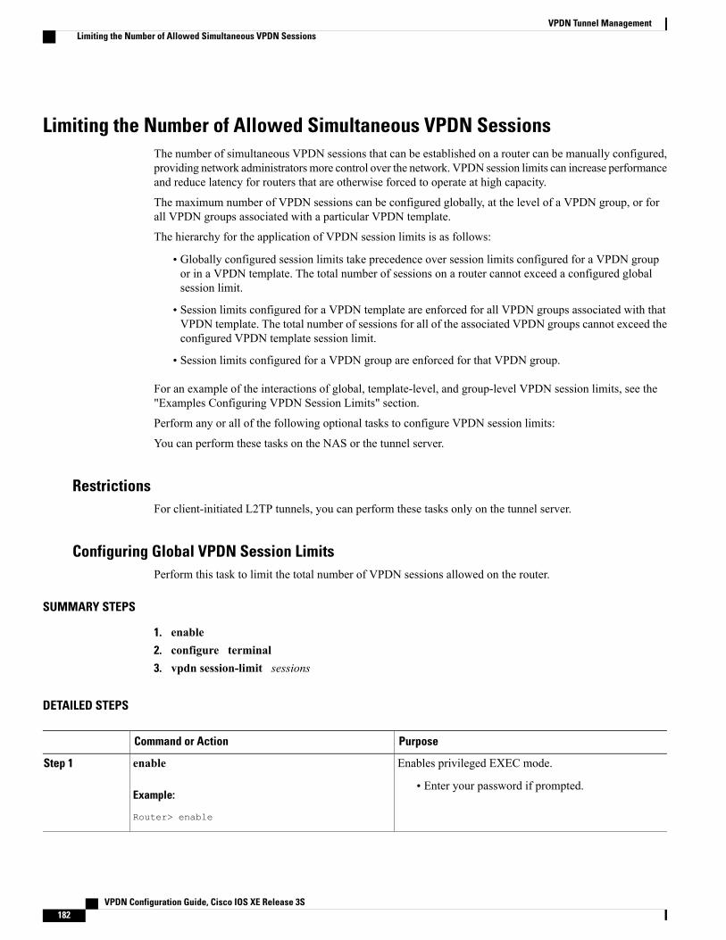
Limiting the Number of Allowed Simultaneous VPDN SessionsThe number of simultaneous VPDN sessions that can be established on a router can be manually configured,providing network administratorsmore control over the network. VPDN session limits can increase performanceand reduce latency for routers that are otherwise forced to operate at high capacity.
The maximum number of VPDN sessions can be configured globally, at the level of a VPDN group, or forall VPDN groups associated with a particular VPDN template.
The hierarchy for the application of VPDN session limits is as follows:
• Globally configured session limits take precedence over session limits configured for a VPDN groupor in a VPDN template. The total number of sessions on a router cannot exceed a configured globalsession limit.
• Session limits configured for a VPDN template are enforced for all VPDN groups associated with thatVPDN template. The total number of sessions for all of the associated VPDN groups cannot exceed theconfigured VPDN template session limit.
• Session limits configured for a VPDN group are enforced for that VPDN group.
For an example of the interactions of global, template-level, and group-level VPDN session limits, see the"Examples Configuring VPDN Session Limits" section.
Perform any or all of the following optional tasks to configure VPDN session limits:
You can perform these tasks on the NAS or the tunnel server.
RestrictionsFor client-initiated L2TP tunnels, you can perform these tasks only on the tunnel server.
Configuring Global VPDN Session LimitsPerform this task to limit the total number of VPDN sessions allowed on the router.
SUMMARY STEPS
1. enable2. configure terminal3. vpdn session-limit sessions
DETAILED STEPS
PurposeCommand or Action
Enables privileged EXEC mode.enableStep 1
Example:
Router> enable
• Enter your password if prompted.
VPDN Configuration Guide, Cisco IOS XE Release 3S182
VPDN Tunnel ManagementLimiting the Number of Allowed Simultaneous VPDN Sessions

PurposeCommand or Action
Enters global configuration mode.configure terminal
Example:
Router# configure terminal
Step 2
Limits the number of simultaneous VPDN sessionsglobally on the router.
vpdn session-limit sessions
Example:
Router(config)# vpdn session-limit 6
Step 3
Configuring VPDN Session Limits in a VPDN TemplatePerform this task to configure a session limit in a VPDN template. The session limit is applied across allVPDN groups associated with the VPDN template.
Before You Begin
• AVPDN templatemust be configured. See the "Creating a VPDNTemplate" section in the "ConfiguringAdditional VPDN Features" module.
• If you configure a named VPDN template, you must associate the desired VPDN groups with the VPDNtemplate. See the "Associating a VPDN Group with a VPDN Template" section in the "ConfiguringAdditional VPDN Features" module.
SUMMARY STEPS
1. enable2. configure terminal3. vpdn-template [name]4. group session-limit sessions
DETAILED STEPS
PurposeCommand or Action
Enables privileged EXEC mode.enableStep 1
Example:
Router> enable
• Enter your password if prompted.
VPDN Configuration Guide, Cisco IOS XE Release 3S 183
VPDN Tunnel ManagementLimiting the Number of Allowed Simultaneous VPDN Sessions

PurposeCommand or Action
Enters global configuration mode.configure terminal
Example:
Router# configure terminal
Step 2
Creates a VPDN template and enters VPDN templateconfiguration mode.
vpdn-template [name]
Example:
Router(config)# vpdn-template l2tp
Step 3
Specifies the maximum number of concurrent sessionsallowed across all VPDN groups associated with a particularVPDN template.
group session-limit sessions
Example:
Router(config-vpdn-templ)# groupsession-limit 6
Step 4
Configuring Session Limits for a VPDN GroupPerform this task to limit the number of VPDN sessions at the VPDN group level.
SUMMARY STEPS
1. enable2. configure terminal3. vpdn-group name4. session-limit number
DETAILED STEPS
PurposeCommand or Action
Enables privileged EXEC mode.enableStep 1
Example:
Router> enable
• Enter your password if prompted.
Enters global configuration mode.configure terminal
Example:
Router# configure terminal
Step 2
VPDN Configuration Guide, Cisco IOS XE Release 3S184
VPDN Tunnel ManagementLimiting the Number of Allowed Simultaneous VPDN Sessions

PurposeCommand or Action
Creates a VPDN group and enters VPDN groupconfiguration mode.
vpdn-group name
Example:
Router(config)# vpdn-group 1
Step 3
Limits the number of sessions that are allowed through aspecified VPDN group.
session-limit number
Example:
Router(config-vpdn)# session-limit 2
Step 4
Verifying VPDN Session LimitsPerform this task to ensure that VPDN sessions are being limited properly.
If you use a Telnet session to connect to the NAS, enable the terminal monitor command, which ensuresthat your EXEC session is receiving the logging and debug output from the NAS.
Note
SUMMARY STEPS
1. enable2. configure terminal3. vpdn session-limit sessions4. Establish a VPDN session by dialing in to the NAS using an allowed username and password.5. Attempt to establish a new VPDN session by dialing in to the NAS using a second allowed username and
password.6. exit7. show vpdn history failure
DETAILED STEPS
Step 1 enableEnter this command to enable privileged EXEC mode. Enter your password if prompted:
Example:
Router> enable
Step 2 configure terminalEnters global configuration mode.
VPDN Configuration Guide, Cisco IOS XE Release 3S 185
VPDN Tunnel ManagementVerifying VPDN Session Limits

Example:
Router# configure terminal
Step 3 vpdn session-limit sessionsLimits the number of simultaneous VPDN sessions on the router to the number specified with the sessions argument.
Issue this command on either the NAS or the tunnel server.
Example:
Router(config)# vpdn session-limit 1
Step 4 Establish a VPDN session by dialing in to the NAS using an allowed username and password.Step 5 Attempt to establish a new VPDN session by dialing in to the NAS using a second allowed username and password.
If VPDN session limits have been configured properly, this session will be refused and a syslog message similar to thefollowing should appear on the console of the router:
Example:
00:11:17:%VPDN-6-MAX_SESS_EXCD:L2F HGW tunnelserver1 has exceeded configured local session-limit andrejected user [email protected]
Step 6 exitExits to privileged EXEC mode.
Step 7 show vpdn history failureShows the content of the history failure table.
Example:
Router# show vpdn history failureUser:[email protected]:NAS1, IP address = 172.25.52.8, CLID = 2Gateway:tunnelserver1, IP address = 172.25.52.7, CLID = 13Log time:00:04:21, Error repeat count:1Failure type:Exceeded configured VPDN maximum session limit.!This output shows that the configured session limit is being properly applied.Failure reason:
Configuring L2TP Control Packet Parameters for VPDN TunnelsControl packet timers, retry counters, and the advertised control packet receive window size can be configuredfor L2TP VPDN tunnels. Adjustments to these parameters allow fine-tuning of router performance to suit theparticular needs of the VPDN deployment.
Perform this task to configure control packet parameters if your VPDN configuration uses L2TP tunnels. Theconfiguration of each parameter is optional. If a parameter is not manually configured, the default value willbe used.
You can perform this task on these devices:
VPDN Configuration Guide, Cisco IOS XE Release 3S186
VPDN Tunnel ManagementConfiguring L2TP Control Packet Parameters for VPDN Tunnels

• The tunnel server
• The NAS when it is functioning as a tunnel endpoint
Before You Begin
Load balancingmust be enabled for the configuration of the l2tp tunnel retransmit initial timeout commandor the l2tp tunnel retransmit initial retries command to have any effect.
For client-initiated L2TP tunnels, you can perform this task only on the tunnel server.Note
SUMMARY STEPS
1. enable2. configure terminal3. vpdn-group name4. l2tp tunnel hello seconds5. l2tp tunnel receive window packets6. l2tp tunnel retransmit retries number7. l2tp tunnel retransmit timeout {min |max} seconds8. l2tp tunnel timeout no-session {seconds | never}9. l2tp tunnel timeout setup seconds10. l2tp tunnel zlb delay seconds11. l2tp tunnel retransmit initial timeout {min |max} seconds12. l2tp tunnel retransmit initial retries number13. l2tp tunnel busy timeout seconds
DETAILED STEPS
PurposeCommand or Action
Enables privileged EXEC mode.enableStep 1
Example:
Router> enable
• Enter your password if prompted.
Enters global configuration mode.configure terminal
Example:
Router# configure terminal
Step 2
VPDN Configuration Guide, Cisco IOS XE Release 3S 187
VPDN Tunnel ManagementConfiguring L2TP Control Packet Parameters for VPDN Tunnels

PurposeCommand or Action
Creates a VPDN group and enters VPDN group configuration mode.vpdn-group name
Example:
Router(config)# vpdn-group group1
Step 3
(Optional) Set the number of seconds between sending hello keepalive packetsfor an L2TP tunnel.
l2tp tunnel hello seconds
Example:
Router(config-vpdn)# l2tp tunnelhello 90
Step 4
• seconds --Time, in seconds, that the NAS and tunnel server will waitbefore sending the next L2TP tunnel keepalive packet. Valid values rangefrom 0 to 1000. The default value is 60.
(Optional) Configures the number of packets allowed in the local receivewindow for an L2TP control channel.
l2tp tunnel receive window packets
Example:
Router(config-vpdn)# l2tp tunnelreceive window 500
Step 5
• packets --Number of packets allowed in the receive window. Valid valuesrange from 1 to 5000. The default value varies by platform.
(Optional) Configures the number of retransmission attempts made for anL2TP control packet.
l2tp tunnel retransmit retries number
Example:
Router(config-vpdn)# l2tp tunnelretransmit retries 8
Step 6
• number --Number of retransmission attempts. Valid values range from5 to 1000. The default value is 10.
(Optional) Configures the amount of time that the router will wait beforeresending an L2TP control packet.
l2tp tunnel retransmit timeout {min |max} seconds
Step 7
Example:
Router(config-vpdn)# l2tp tunnelretransmit timeout max 4
• min --Specifies the minimum time that the router will wait beforeresending a control packet.
• max --Specifies the maximum time that the router will wait beforeresending a control packet.
• seconds --Timeout length, in seconds, the router will wait beforeresending a control packet. Valid values range from 1 to 8. The defaultminimum value is 1. The default maximum value is 8.
(Optional) Configures the time a router waits after an L2TP tunnel becomesempty before tearing down the tunnel.
l2tp tunnel timeout no-session {seconds| never}
Step 8
Example:
Router(config-vpdn)# l2tp tunneltimeout no-session never
• seconds --Time, in seconds, the router will wait before tearing down anempty L2TP tunnel. Valid values range from 0 to 86400. If the router isconfigured as a NAS, the default is 15 seconds. If the router is configuredas a tunnel server, the default is 10.
• never --Specifies that the router will never tear down an empty L2TPtunnel.
VPDN Configuration Guide, Cisco IOS XE Release 3S188
VPDN Tunnel ManagementConfiguring L2TP Control Packet Parameters for VPDN Tunnels

PurposeCommand or Action
(Optional) Configures the amount of time that the router will wait for aconfirmation message after sending out the initial L2TP control packet beforeconsidering a peer busy.
l2tp tunnel timeout setup seconds
Example:
Router(config-vpdn)# l2tp tunneltimeout setup 25
Step 9
• seconds --Time, in seconds, the router will wait for a confirmationmessage. Valid values range from 60 to 6000. The default value is 10.
(Optional) Configures the delay time before a zero length bit (ZLB) controlmessage must be acknowledged.
l2tp tunnel zlb delay seconds
Example:
Router(config-vpdn)# l2tp tunnelzlb delay 2
Step 10
• seconds --Maximum number of seconds the router will delay beforeacknowledging ZLB control messages. Valid values range from 1 to 5.The default value is 3.
(Optional) Sets the amount of time, in seconds, that the router will wait beforeresending an initial packet out to establish a tunnel.
l2tp tunnel retransmit initial timeout{min |max} seconds
Step 11
Example:
Router(config-vpdn)# l2tp tunnelretransmit initial timeout min 2
• min --Specifies the minimum time that the router will wait beforeresending an initial packet.
• max --Specifies the maximum time that the router will wait beforeresending an initial packet.
• seconds --Timeout length, in seconds, the router will wait beforeresending an initial packet. Valid values range from 1 to 8. The defaultminimum value is 1. The default maximum value is 8.
Load balancing must be configured for the retry counter configuredwith the l2tp tunnel retransmit initial timeout command to takeeffect.
Note
(Optional--Cisco IOS Release 12.2(4)T, Cisco IOS Release 12.2(28)SB, or alater release) Sets the number of times that the router will attempt to send out
l2tp tunnel retransmit initial retriesnumber
Step 12
the initial control packet for tunnel establishment before considering a routerbusy.Example:
Router(config-vpdn)# l2tp tunnelretransmit initial retries 5
• number --Number of retransmission attempts. Valid values range from1 to 1000. The default value is 2.
Load balancing must be configured for the retry counter configuredwith the l2tp tunnel retransmit initial retries command to takeeffect.
Note
(Optional) Configures the amount of time, in seconds, that the router will waitbefore attempting to recontact a router that was previously busy.
l2tp tunnel busy timeout seconds
Example:
Router(config-vpdn)# l2tp tunnelbusy timeout 90
Step 13
• seconds --Time, in seconds, the router will wait before checking forrouter availability. Valid values range from 60 to 6000. The default valueis 300.
VPDN Configuration Guide, Cisco IOS XE Release 3S 189
VPDN Tunnel ManagementConfiguring L2TP Control Packet Parameters for VPDN Tunnels

Configuring L2TP Congestion AvoidancePerform this task to configure L2TP congestion avoidance on a tunnel endpoint, allowing dynamic throttlingof the L2TP control packet window size.
You can perform this task on these devices:
• The tunnel server
• The NAS when it is functioning as a tunnel endpoint
This task need be performed only on the sending device.
Note • This task is compatible only with VPDN deployments that use the L2TP tunneling protocol.
• For client-initiated L2TP tunnels, you can perform this task only on the tunnel server.
• The congestion window size cannot exceed the size of the advertised receive window set by the l2tptunnel receive-window command on the peer device. To configure the advertised receive windowon the remote peer device, see the Configuring L2TPControl Packet Parameters for VPDNTunnels,on page 186.
• L2TP congestion avoidance is enabled (or disabled) only for those tunnels that are established afterthe configuration has been applied. Tunnels that already exist when the l2tp congestion-controlcommand is issued are not affected by the command.
SUMMARY STEPS
1. enable2. configure terminal3. l2tp congestion-control4. exit5. show vpdn tunnel l2tp all6. debug vpdn l2x-events
DETAILED STEPS
PurposeCommand or Action
Enables privileged EXEC mode.enableStep 1
Example:
Router> enable
• Enter your password if prompted.
VPDN Configuration Guide, Cisco IOS XE Release 3S190
VPDN Tunnel ManagementConfiguring L2TP Congestion Avoidance

PurposeCommand or Action
Enters global configuration mode.configure terminal
Example:
Router# configure terminal
Step 2
Enables L2TP congestion avoidance.l2tp congestion-control
Example:
Router(config)# l2tp congestion-control
Step 3
Exits to privileged EXEC mode.exit
Example:
Router(config)# exit
Step 4
Displays information about all active L2TP VPDNtunnels.
show vpdn tunnel l2tp all
Example:
Router# show vpdn tunnel l2tp all
Step 5
Displays troubleshooting information forprotocol-specific VPDN tunneling events.
debug vpdn l2x-events
Example:
Router(config)# debug vpdn l2x-events
Step 6
Configuring VPDN Failure Event LoggingLogging of a failure event to the history table is triggered by event logging by the syslog facility. The syslogfacility creates a history failure table, which keeps records of failure events. The table defaults to a maximumof 20 entries, but the size of the table can be configured to retain up to 50 entries.
Failure entries are kept chronologically in the history table. Each entry records the relevant information of afailure event. Only the most recent failure event per user, unique to its name and tunnel client ID (CLID), iskept. When the total number of entries in the table reaches the configured maximum table size, the oldestrecord is deleted and a new entry is added.
The logging of VPDN failure events to the VPDN history failure table is enabled by default. You need enableVPDN failure event logging only if it has been previously disabled. Perform this task to enable VPDN failureevent logging, to configure the maximum number of entries the history failure table can hold, and to displayand clear the contents of the VPDN history failure table.
VPDN Configuration Guide, Cisco IOS XE Release 3S 191
VPDN Tunnel ManagementConfiguring VPDN Failure Event Logging

SUMMARY STEPS
1. enable2. configure terminal3. vpdn history failure4. vpdn history failure table-size entries5. exit6. show vpdn history failure7. clear vpdn history failure
DETAILED STEPS
PurposeCommand or Action
Enables privileged EXEC mode.enableStep 1
Example:
Router> enable
• Enter your password if prompted.
Enters global configuration mode.configure terminal
Example:
Router# configure terminal
Step 2
(Optional) Enables logging of VPDN failure events to the historyfailure table.
vpdn history failure
Example:
Router(config)# vpdn history failure
Step 3
VPDN history failure logging is enabled by default. Youneed issue the vpdn history failure command only if youhave previously disabled VPDN history failure loggingusing the no vpdn history failure command.
Note
(Optional) Sets the history failure table size.vpdn history failure table-size entriesStep 4
Example:
Router(config)# vpdn history failuretable-size 50
The VPDN history failure table size can be configuredonly when VPDN failure event logging is enabled usingthe vpdn history failure command.
Note
Exits to privileged EXEC mode.exit
Example:
Router# exit
Step 5
(Optional) Displays the contents of the history failure table.show vpdn history failure
Example:
Router# show vpdn history failure
Step 6
VPDN Configuration Guide, Cisco IOS XE Release 3S192
VPDN Tunnel ManagementConfiguring VPDN Failure Event Logging

PurposeCommand or Action
(Optional) Clears the contents of the history failure table.clear vpdn history failure
Example:
Router# clear vpdn history failure
Step 7
Enabling Generic VPDN Event LoggingGeneric VPDN events are a mixture of error, warning, notification, and information reports logged by thesyslog facility. When VPDN event logging is enabled locally or at a remote tunnel endpoint, VPDN eventmessages are printed to the console as the events occur. VPDN event messages can also be reported to aremote authentication, authorization, and accounting (AAA) server in a AAA vendor-specific attribute (VSA),allowing the correlation of VPDN call success rates with accounting records.
SUMMARY STEPS
1. enable2. configure terminal3. vpdn logging [accounting | local | remote | tunnel-drop | user]
DETAILED STEPS
PurposeCommand or Action
Enables privileged EXEC mode.enableStep 1
Example:
Router> enable
• Enter your password if prompted.
Enters global configuration mode.configure terminal
Example:
Router# configure terminal
Step 2
(Optional) Enables the logging of generic VPDN events.vpdn logging [accounting | local | remote |tunnel-drop | user]
Step 3
• You can configure as many types of generic VPDN event loggingas you want by issuing multiple instances of the vpdn loggingcommand.Example:
Router(config)# vpdn logging remoteThe reporting of VPDN event log messages to a AAA servercan be enabled independently of all other generic VPDN eventlogging configurations.
Note
VPDN Configuration Guide, Cisco IOS XE Release 3S 193
VPDN Tunnel ManagementEnabling Generic VPDN Event Logging

PurposeCommand or Action
Configuration Examples for VPDN Tunnel Management
Examples Manually Terminating VPDN TunnelsThe following example manually terminates all L2TP tunnels that terminate on the router:
Router# clear vpdn tunnel l2tp all
Example Enabling Soft Shutdown of VPDN TunnelsThe following example enables soft shutdown of all VPDN tunnels that terminate on the device that thecommand is issue on:
Router# configure terminalRouter(config)# vpdn softshut!The following syslog message will appear on the device whenever an attempt is made to!establish a new VPDN session after soft shutdown is enabled.!00:11:17:%VPDN-6-SOFTSHUT:L2TP HGW tunnelserver1 has turned on softshut and rejected [email protected]
Examples Configuring VPDN Session LimitsThe following example configures a VPDN group named customer7 with a group-level session limit of 25.No more than 25 sessions can be associated with this VPDN group.
Router(config)# vpdn-group customer7Router(config-vpdn)# session-limit 25A VPDN template named customer4 is then created, and a session limit of 8 is configured at the VPDNtemplate level. Two VPDN groups are associated with the VPDN template, each with a VPDN group-levelsession limit of 5.
Router(config)# vpdn-template customer4Router(config-vpdn-templ)# group session-limit 8!Router(config)# vpdn-group customer4_l2tpRouter(config-vpdn)# source vpdn-template customer4Router(config-vpdn)# session-limit 5!Router(config)# vpdn-group customer4_l2fRouter(config-vpdn)# source vpdn-template customer4Router(config-vpdn)# session-limit 5With this configuration, if the VPDN group named customer4_l2tp has 5 active sessions, the VPDN groupnamed customer4_l2f can establish only 3 sessions. The VPDN group named customer7 can still have up to25 active sessions.
VPDN Configuration Guide, Cisco IOS XE Release 3S194
VPDN Tunnel ManagementConfiguration Examples for VPDN Tunnel Management

If a global limit of 16 VPDN sessions is also configured, the global limit takes precedence over the configuredVPDN group and VPDN template session limits:
Router# configure terminalRouter(config)# vpdn session-limit 16The three VPDN groups will be able to establish a total of 16 sessions between them. For example, if theVPDN group named customer4_l2tp has the maximum allowable number of active sessions (5 sessions), andthe VPDN group named customer4_l2f has 2 active sessions, the VPDN group named customer7 can establishonly up to 9 sessions.
Example Verifying Session Limits for a VPDN GroupThe following example creates the VPDN group named l2tp and restricts it to three sessions. The configuredsession limit is displayed when the show vpdn group command is issued.
Router# configure terminalRouter(config)# vpdn-group l2tpRouter(config-vpdn)# accept dialinRouter(config-vpdn-acc-in)# protocol l2tpRouter(config-vpdn-acc-in)# virtual-template 5Router(config-vpdn-acc-in)# exitRouter(config-vpdn)# terminate-from hostname host1Router(config-vpdn)# session-limit 3Router(config-vpdn)# endRouter# show vpdn group l2tpTunnel (L2TP)------dnis:cg1dnis:cg2dnis:jancisco.comEndpoint Session Limit Priority Active Sessions Status Reserved Sessions-------- ------------- -------- --------------- ------ -----------------172.21.9.67 3 1 0 OK ---------------- ------------- --------------- -----------------Total * 0 0
Example Configuring L2TP Control Packet Timers and Retry Counters for VPDNTunnels
The following example configures custom values for all of the available L2TP control packet parameters forthe VPDN group named l2tp:
Router# configure terminal
Router(config)# vpdn-group l2tp
Router(config-vpdn)# l2tp tunnel hello 90Router(config-vpdn)# l2tp tunnel receive window 500Router(config-vpdn)# l2tp tunnel retransmit retries 8Router(config-vpdn)# l2tp tunnel retransmit timeout min 2Router(config-vpdn)# l2tp tunnel timeout no-session 500Router(config-vpdn)# l2tp tunnel timeout setup 25Router(config-vpdn)# l2tp tunnel zlb delay 4Router(config-vpdn)# l2tp tunnel retransmit initial timeout min 2Router(config-vpdn)# l2tp tunnel retransmit initial retries 5Router(config-vpdn)# l2tp tunnel busy timeout 90
VPDN Configuration Guide, Cisco IOS XE Release 3S 195
VPDN Tunnel ManagementExample Verifying Session Limits for a VPDN Group

Example Configuring Verifying and Debugging L2TP Congestion AvoidanceThe following example configures a basic dial-in L2TP VPDN tunnel, sets the receive window size to 500on the tunnel server (the receiving device), and enables L2TP congestion avoidance on the NAS (the sendingdevice):
Tunnel Server Configuration
Router(config)# vpdn enable!Router(config)# vpdn-group 1Router(config-vpdn)# accept-dialinRouter(config-vpdn-acc-in)# protocol l2tpRouter(config-vpdn-acc-in)# virtual-template 1!Router(config-vpdn)# terminate from hostname NAS1Router(config-vpdn)# l2tp tunnel receive-window 500
NAS Configuration
Router(config)# vpdn enable!Router(config)# vpdn-group 1Router(config-vpdn)# request-dialinRouter(config-vpdn-req-in)# protocol l2tpRouter(config-vpdn-req-in)# domain cisco.com!Router(config-vpdn)# initiate-to ip 172.22.66.25Router(config-vpdn)# local name NAS1!Router(config)# l2tp congestion-controlThe following example shows L2TP tunnel activity, including the information that L2TP congestion controlis enabled. Note that the slow start threshold is set to the same size as the remote receive window size. TheRemote RWS value advertised by the remote peer is shown in the Remote RWS field. When the actual RWSvalue differs from the advertised value, the actual RWS value will be displayed as In Use Remote RWS<value>.
Router# show vpdn tunnel l2tp allL2TP Tunnel Information Total tunnels 1 sessions 1Tunnel id 30597 is up, remote id is 45078, 1 active sessionsTunnel state is established, time since change 00:08:27Tunnel transport is UDP (17)Remote tunnel name is LAC1Internet Address 172.18.184.230, port 1701
Local tunnel name is LNS1Internet Address 172.18.184.231, port 1701
Tunnel domain unknownVPDN group for tunnel is 1L2TP class for tunnel is4 packets sent, 3 received194 bytes sent, 42 receivedLast clearing of "show vpdn" counters neverControl Ns 2, Nr 4Local RWS 1024 (default), Remote RWS 256In Use Remote RWS 15Control channel Congestion Control is enabledCongestion Window size, Cwnd 3Slow Start threshold, Ssthresh 256Mode of operation is Slow Start
Tunnel PMTU checking disabledRetransmission time 1, max 2 secondsUnsent queuesize 0, max 0
VPDN Configuration Guide, Cisco IOS XE Release 3S196
VPDN Tunnel ManagementExample Configuring Verifying and Debugging L2TP Congestion Avoidance

Resend queuesize 0, max 1Total resends 0, ZLB ACKs sent 2Current nosession queue check 0 of 5Retransmit time distribution: 0 0 0 0 0 0 0 0 0Sessions disconnected due to lack of resources 0Control message authentication is disabled
The following partial output from the debug vpdn l2x-events command shows that congestion occurred. Thecongestion window size and the slow start threshold have been reset due to a packet retransmission event.
Router# debug vpdn l2x-events!*Jul 15 19:02:57.963: Tnl 47100 L2TP: Congestion Control event received is retransmission*Jul 15 19:02:57.963: Tnl 47100 L2TP: Congestion Window size, Cwnd 1*Jul 15 19:02:57.963: Tnl 47100 L2TP: Slow Start threshold, Ssthresh 2*Jul 15 19:02:57.963: Tnl 47100 L2TP: Remote Window size, 500*Jul 15 19:02:57.963: Tnl 47100 L2TP: Control channel retransmit delay set to 4 seconds*Jul 15 19:03:01.607: Tnl 47100 L2TP: Update ns/nr, peer ns/nr 2/5, our ns/nr 5/2!The following partial output from the debug vpdn l2x-events command shows that traffic has been restartedwith L2TP congestion avoidance operating in slow start mode.
Router# debug vpdn l2x-events!*Jul 15 14:45:16.123: Tnl 30597 L2TP: Control channel retransmit delay set to 2 seconds*Jul 15 14:45:16.123: Tnl 30597 L2TP: Tunnel state change from idle to wait-ctl-reply*Jul 15 14:45:16.131: Tnl 30597 L2TP: Congestion Control event received is positiveacknowledgement*Jul 15 14:45:16.131: Tnl 30597 L2TP: Congestion Window size, Cwnd 2*Jul 15 14:45:16.131: Tnl 30597 L2TP: Slow Start threshold, Ssthresh 500*Jul 15 14:45:16.131: Tnl 30597 L2TP: Remote Window size, 500*Jul 15 14:45:16.131: Tnl 30597 L2TP: Congestion Ctrl Mode is Slow Start!
Example Configuring VPDN Failure Event LoggingThe following example first disables and then reenables VPDN failure event logging, and sets the maximumnumber of entries in the VPDN history failure table to 50. The contents of the history failure table are displayedand then cleared.
Router# configure terminalRouter(config)# no vpdn history failureRouter(config)# vpdn history failureRouter(config)# vpdn history failure table-size 50Router(config)# endRouter# show vpdn history failure!Table size: 50Number of entries in table: 1User: [email protected], MID = 1NAS: isp, IP address = 172.21.9.25, CLID = 1Gateway: hp-gw, IP address = 172.21.9.15, CLID = 1Log time: 13:08:02, Error repeat count: 1Failure type: The remote server closed this sessionFailure reason: Administrative intervention!Router# clear vpdn history failure
VPDN Configuration Guide, Cisco IOS XE Release 3S 197
VPDN Tunnel ManagementExample Configuring VPDN Failure Event Logging

Examples Configuring Generic VPDN Event LoggingThe following example enables VPDN logging locally:
Router# configure terminalRouter(config)# vpdn logging localThe following example disables VPDN event logging locally, enables VPDN event logging at the remotetunnel endpoint, and enables the logging of both VPDN user and VPDN tunnel-drop events to the remoterouter:
Router# configure terminalRouter(config)# no vpdn logging localRouter(config)# vpdn logging remoteRouter(config)# vpdn logging userRouter(config)# vpdn logging tunnel-dropThe following example disables the logging of VPDN events at the remote tunnel endpoint, and enables thelogging of VPDN event log messages to the AAA server:
Router# configure terminalRouter(config)# no vpdn logging localRouter(config)# no vpdn logging remoteRouter(config)# vpdn logging accounting
Additional ReferencesRelated Documents
Document TitleRelated Topic
Cisco IOS Master Commands List, All ReleasesCisco IOS commands
VPDN Technology Overview moduleVPDN technology overview
Cisco IOS VPDN Command ReferenceVPDN commands: complete command syntax,command mode, defaults, usage guidelines, andexamples
Virtual Private Dial-up Network (VPDN)Technical support documentation for VPDNs
Cisco IOS Dial Technologies Command ReferenceDial Technologies commands: complete commandsyntax, command mode, defaults, usage guidelines,and examples
Configuring Additional VPDN Features moduleConcepts and tasks associated with configuringadditional VPDN features
VPDN Configuration Guide, Cisco IOS XE Release 3S198
VPDN Tunnel ManagementExamples Configuring Generic VPDN Event Logging

Standards
TitleStandard
TCP/IP Illustrated, Volume 1TCP/IP; slow start and congestion avoidancealgorithms
MIBs
MIBs LinkMIB
To locate and downloadMIBs for selected platforms,Cisco software releases, and feature sets, use CiscoMIB Locator found at the following URL:
http://www.cisco.com/go/mibs
• CISCO-VPDN-MGMT-MIB
• CISCO-VPDN-MGMT-EXT-MIB
RFCs
TitleRFC
Layer Two Tunneling Protocol (L2TP)RFC 2661
Technical Assistance
LinkDescription
http://www.cisco.com/cisco/web/support/index.htmlThe Cisco Support and Documentation websiteprovides online resources to download documentation,software, and tools. Use these resources to install andconfigure the software and to troubleshoot and resolvetechnical issues with Cisco products and technologies.Access to most tools on the Cisco Support andDocumentation website requires a Cisco.com user IDand password.
Feature Information for VPDN Tunnel ManagementThe following table provides release information about the feature or features described in this module. Thistable lists only the software release that introduced support for a given feature in a given software releasetrain. Unless noted otherwise, subsequent releases of that software release train also support that feature.
Use Cisco Feature Navigator to find information about platform support and Cisco software image support.To access Cisco Feature Navigator, go to www.cisco.com/go/cfn. An account on Cisco.com is not required.
VPDN Configuration Guide, Cisco IOS XE Release 3S 199
VPDN Tunnel ManagementFeature Information for VPDN Tunnel Management

Table 13: Feature Information for VPDN Tunnel Management
Feature InformationReleasesFeature Name
This feature was introduced on theCisco ASR 1000 SeriesAggregation Services Routers. Itprovides packet flow control andcongestion avoidance by throttlingLayer 2 Transport Protocol (L2TP)control messages as described inRFC 2661.
The following commands wereintroduced or modified by thisfeature: debug vpdn, l2tpcongestion-control.
Cisco IOS XE Release 2.3L2TP Congestion Avoidance
This feature was introduced on theCisco ASR 1000 SeriesAggregation Services Routers. Itallows you to apply session limitson all VPDN groups associatedwith a common VPDN template.You can limit the number of VPDNsessions that terminate in a singleVPN routing and forwarding(VRF) instance.
The following commands wereintroduced or modified by thisfeature: group session-limit,source vpdn-template, andvpdn-template.
Cisco IOS XE Release 2.1Session Limit per VRF
This feature was introduced on theCisco ASR 1000 SeriesAggregation Services Routers. Itallows the user to configure certainadjustable timers and counters forL2TP.
The following commands wereintroduced by this feature: l2tptunnel busy timeout, l2tp tunnelretransmit initial retries, and l2tptunnel retransmit initial timeout.
Cisco IOS XE Release 2.1Timer and Retry Enhancements forL2TP
VPDN Configuration Guide, Cisco IOS XE Release 3S200
VPDN Tunnel ManagementFeature Information for VPDN Tunnel Management

Feature InformationReleasesFeature Name
This feature was introduced on theCisco ASR 1000 SeriesAggregation Services Routers. Itallows the user to configure a limiton the number L2TP VPDNsessions allowed for each VPDNgroup.
The following command wasintroduced by this feature:session-limit (VPDN).
Cisco IOS XE Release 2.1VPDN Group Session Limiting
VPDN Configuration Guide, Cisco IOS XE Release 3S 201
VPDN Tunnel ManagementFeature Information for VPDN Tunnel Management

VPDN Configuration Guide, Cisco IOS XE Release 3S202
VPDN Tunnel ManagementFeature Information for VPDN Tunnel Management

C H A P T E R 7Configuring L2TP HA Session SSO ISSU on a LACLNS
The L2TP HA Session SSO/ISSU on a LAC/LNS feature provides a generic stateful switchover/In ServiceSoftware Upgrade (SSO/ISSU) mechanism for Layer 2 Tunneling Protocol (L2TP) on a Layer 2 AccessConcentrator (LAC) and a Layer 2 Network Server (LNS). This feature preserves all fully established PPPand L2TP sessions during an SSO switchover or an ISSU upgrade or downgrade.
• Finding Feature Information, page 203
• Prerequisites for L2TP HA Session SSO ISSU on a LAC LNS, page 203
• Restrictions for L2TP HA Session SSO ISSU on a LAC LNS, page 204
• Information About L2TP HA Session SSO ISSU on a LAC LNS, page 204
• How to Configure L2TP HA Session SSO ISSU on a LAC LNS, page 206
• Configuration Examples for L2TP HA Session SSO ISSU on a LAC LNS, page 215
• Additional References, page 217
• Feature Information for L2TP HA Session SSO ISSU on a LAC LNS, page 218
Finding Feature InformationYour software release may not support all the features documented in this module. For the latest caveats andfeature information, see Bug Search Tool and the release notes for your platform and software release. Tofind information about the features documented in this module, and to see a list of the releases in which eachfeature is supported, see the feature information table.
Use Cisco Feature Navigator to find information about platform support and Cisco software image support.To access Cisco Feature Navigator, go to www.cisco.com/go/cfn. An account on Cisco.com is not required.
Prerequisites for L2TP HA Session SSO ISSU on a LAC LNS• Configure a VPDN deployment. For an overview of VPDN deployments, see the VPDN TechnologyOverview module.
VPDN Configuration Guide, Cisco IOS XE Release 3S 203

• This implementation does not require the peer L2TP node to be HA or redundancy aware. It does notrequire the peer L2TP node to implement L2TP failover RFC.
• Ensure that the peer L2TP node is L2TP RFC compliant.
Restrictions for L2TP HA Session SSO ISSU on a LAC LNS• Cisco IOS XE Release 2.2 provides support for the L2TP HA Session SSO/ISSU on a LAC/LNS featureon Cisco ASR 1000 Series Routers only.
• Cisco IOS XE Release 2.4 provides support for VPDNMultihop nodes for VPDN tunnels and sessions.VPDN tunnels and sessions are preserved after a Route Processor (RP) failover in a dual RP ASR setup.
• L2TP HA Session SSO/ISSU on a LAC/LNS does not support HA/SSO on the following softwarefeatures, and sessions with these will be lost following an RP failover:
• L2TP Dialout
• L2TP Active Discovery Relay for PPPoE
• Multilink PPP on LNS
Information About L2TP HA Session SSO ISSU on a LAC LNS
Stateful SwitchoverDevelopment of the stateful switchover (SSO) feature is an incremental step within an overall program toimprove the availability of networks constructed with Cisco IOS routers.
In specific Cisco networking devices that support dual RPs, stateful switchover takes advantage of RPredundancy to increase network availability. The feature establishes one of the RPs as the active processorand designating the other RP as the standby processor, and then synchronizing critical state informationbetween them. Following an initial synchronization between the two processors, SSO dynamically maintainsRP state information between them.
A switchover from the active to the standby processor occurs when the active RP fails, is removed from thenetworking device, or is manually taken down for maintenance.
SSO is particularly useful at the network edge. Traditionally, core routers protect against network faults usingrouter redundancy and mesh connections that allow traffic to bypass failed network elements. SSO providesprotection for network edge devices with dual RPs that represent a single point of failure in the network design,and where an outage might result in loss of service for customers.
VPDN Configuration Guide, Cisco IOS XE Release 3S204
Configuring L2TP HA Session SSO ISSU on a LAC LNSRestrictions for L2TP HA Session SSO ISSU on a LAC LNS

If a new L2TP session request is received on a tunnel that is in the resync phase after switchover, it isrejected. A new Cisco vendor-specific disconnect cause code (611) provides the reason for this sessiondisconnect. The show vpdn history failure command displays the Failure Type field as Tunnel in HAresync .
Note
Checkpointing DataSSO is always checkpointing or saving and resynchronizing client-specific state data that transfers to a peerclient on a remote RP for HA switchover and on the local RP for ION restart. Once a valid checkpointingsession is established, the checkpointed state data is established without error.
ISSU Software Superpackage and Rolling Upgrade RequirementsThis section describes the affects on L2TP when performing an ISSU superpackage or subpackage softwareupgrade or downgrade on a Cisco ASR 1000 Series Router. During the ISSU operation of software upgradesand downgrades, there can be control traffic interruption in some scenarios of ISSU, causing the L2TPresynchronization operation (with L2TP silent switchover) to fail, resulting in a loss of an L2TP tunnel orsession.
In general, there is no effect on the data traffic while performing an ISSU superpackage or subpackage softwareupgrade or downgrade. Data traffic interruptions are contained within a managed and expected operating set.For example, when you upgrade the software for a given spa, the software upgrade only affects the data trafficserviced by that spa; the remaining network continues to operate normally.
Software Upgrades and DowngradesWhen you are configuring a superpackage software upgrade or downgrade, L2TP sessions and tunnels mightbe lost. To help mitigate any potential loss of L2TP tunnels or sessions, use a rolling-upgrade method to helpminimize any L2TP tunnel or session outages.
You can help minimize any tunnel or session outage as seen by the IP layer, by either configuring a backupinterface for IP routing or an Ether-channel interface towards the L2TP peer.
Note
For the Cisco ASR 1000 Series Routers, it is important to realize that ISSU-compatibility depends on thesoftware sub-package being upgraded and the hardware configuration. Consolidated packages areISSU-compatible in dual RP configurations only and have other limitations. The SPA and SIP softwaresub-packages must be upgraded on a per-SPA or per-SIP basis.
If you are upgrading a software package on the Cisco ASR 1000 Series Router that requires a reload of thestandby Route Processor (RP), you must manually initiate a upgrade of the standby FP, SPA and SIP softwarewith the same version of software provisioned on the new active RP following the switchover, to prevent anyreload when the standby RP takes over as the new active RP.
VPDN Configuration Guide, Cisco IOS XE Release 3S 205
Configuring L2TP HA Session SSO ISSU on a LAC LNSCheckpointing Data

Adjusting Receive Window SizeWhen configuring L2TP HA Session SSO/ISSU on a LAC/LNS, Cisco IOS software internally adjusts theL2TP receive window size to a smaller value. This adjusted receive-window value displays when using theshow vpdn tunnel detail command. If required, use the l2tp tunnel resync command to increase the size ofthe L2TP receive window.
How to Configure L2TP HA Session SSO ISSU on a LAC LNSYou can configure L2TP HA globally using the l2tp sso enable command. You can also configure L2TP HAsessions for a specific VPDN group by using the sso enable command in VPDN group configuration mode.Both global and VPDN group L2TP HA sessions are enabled, by default. You must configure both the l2tpsso enable command and the sso enable command for VPDN groups for protocol L2TP to execute L2TP HAsession functionality.
Global and VPDN group-specific L2TP HA sessions are hidden from the output of the show running-configcommand, because they are enabled by default. If you use the no l2tp sso enable command, the HA commandswill display as NVGEN and appear in the output of the show running-config command.
After an SSO switchover, L2TP HA sessions determines the sequence numbers used by L2TP peers.Determining sequence numbers can be time consuming if peers send a large number of unacknowledgedmessages. You can use the l2tp tunnel resync command to control the number of unacknowledged messagessent by a peer. Increasing the value of the number of packets can improve the session setup rate for L2TP HAtunnels with a large number of sessions.
Configuring SSO on a Route ProcessorCisco series Internet routers operate in SSO mode by default after reloading the same version of SSO-awareimages on the device.
Before you can use SSO, use must enable SSO on an RP. This task explains how to use the redundancycommand to enable SSO on an RP. This task ensures that all redundancy session data, following a SSO, isused to re-create and reestablishes existing sessions to their peer connections.
SUMMARY STEPS
1. enable2. configure terminal3. redundancy4. mode sso5. end
DETAILED STEPS
PurposeCommand or Action
Enables privileged EXEC mode.enableStep 1
VPDN Configuration Guide, Cisco IOS XE Release 3S206
Configuring L2TP HA Session SSO ISSU on a LAC LNSHow to Configure L2TP HA Session SSO ISSU on a LAC LNS

PurposeCommand or Action
Example:
Router> enable
• Enter your password if prompted.
Enters global configuration mode.configure terminal
Example:
Router# configure terminal
Step 2
Enters redundancy configuration mode.redundancy
Example:
Router(config)# redundancy
Step 3
Specifies the mode of redundancy.mode sso
Example:
Router(config-red)# mode sso
Step 4
Returns to privileged EXEC mode.end
Example:
Router(config-red)# end
Step 5
Configuring Global L2TP HA SSO ModeCisco series Internet routers operate in L2TP HA SSO mode by default after reloading the same version ofSSO-aware images on the device. No configuration is necessary to enable L2TP HA SSO sessions.
This procedure shows how to use the l2tp sso enable command to enable or disable HA globally. The l2tpsso enable command is enabled by default.
SUMMARY STEPS
1. enable2. configure terminal3. l2tp sso enable4. end
VPDN Configuration Guide, Cisco IOS XE Release 3S 207
Configuring L2TP HA Session SSO ISSU on a LAC LNSConfiguring Global L2TP HA SSO Mode

DETAILED STEPS
PurposeCommand or Action
Enables privileged EXEC mode.enableStep 1
Example:
Router> enable
• Enter your password if prompted.
Enters global configuration mode.configure terminal
Example:
Router# configure terminal
Step 2
Enables L2TP HA SSO.l2tp sso enable
Example:
Router(config)# l2tp sso enable
Step 3
Returns to privileged EXEC mode.end
Example:
Router(config)# end
Step 4
Configuring VPDN Groups or VPDN Templates for L2TP HA SSOPerform this task when configuring a VPDN group or a VPDN template for L2TPHA SSO. This configurationexample provides recommended scaling parameters to use when the number of VPDN tunnels in use is high,such as 8000 tunnels, with each tunnel supporting only a few VPDN sessions (two or less).
Conversely, if the number of VPDN tunnels is low and the number of VPDN sessions per VPDN tunnel ishigh, use the l2tp tunnel resync command to increase the resynchronization value. For example, if the numberof VPDN session per VPDN tunnel are in the hundreds, use the l2tp tunnel resync command to increase theresynchronization value to a matching value in the hundreds.
Beginning with Cisco IOS XE Release 2.3, you can set the retransmit retries and timeout values to defaultvalues.
For HA functionality for a VPDN group, both the l2tp sso enable and sso enable commands must be enabled(default). If either command is disabled, no HA functionality is available for the VPDN group.
VPDN Configuration Guide, Cisco IOS XE Release 3S208
Configuring L2TP HA Session SSO ISSU on a LAC LNSConfiguring VPDN Groups or VPDN Templates for L2TP HA SSO

SUMMARY STEPS
1. enable2. configure terminal3. l2tp sso enable4. vpdn enable5. vpdn-group name6. sso enable7. l2tp tunnel resync packets8. l2tp tunnel retransmit retries number9. l2tp tunnel retransmit timeout min seconds10. exit
DETAILED STEPS
PurposeCommand or Action
Enables privileged EXEC mode.enableStep 1
Example:
Router> enable
• Enter your password if prompted.
Enters global configuration mode.configure terminal
Example:
Router# configure terminal
Step 2
Enables L2TP SSO mode.l2tp sso enable
Example:
Router(config)# l2tp sso enable
Step 3
Enters VPDN configuration mode.vpdn enable
Example:
Router(config)# vpdn enable
Step 4
Creates a VPDN group and enters VPDN groupconfiguration mode.
vpdn-group name
Example:
Router(config-vpdn)# vpdn-group example
Step 5
VPDN Configuration Guide, Cisco IOS XE Release 3S 209
Configuring L2TP HA Session SSO ISSU on a LAC LNSConfiguring VPDN Groups or VPDN Templates for L2TP HA SSO

PurposeCommand or Action
Enables L2TP SSO for the VPDN group.sso enable
Example:
Router(config-vpdn)# sso enable
Step 6
Configures the number of packets after an SSO, an L2TPHA tunnel sends before waiting for an acknowledgement.
l2tp tunnel resync packets
Example:
Router(config-vpdn)# l2tp tunnel resync 4
Step 7
Configures the number of retransmission attempts madefor an L2TP control packet.
l2tp tunnel retransmit retries number
Example:
Router(config-vpdn)# l2tp tunnel retransmitretries 30
Step 8
Configures the amount of time that the router waits beforeresending an L2TP control packet.
l2tp tunnel retransmit timeout min seconds
Example:
Router(config-vpdn)# l2tp tunnel retransmittimeout min 8
Step 9
Exits VPDN group configuration mode.exit
Example:
Router(config-vpdn)# exit
Step 10
Controlling Packet Resynchronization for L2TP HAAfter a SSO switchover, L2TP HA determines the sequence numbers used by L2TP peers. Determiningsequence numbers can be time consuming, if peers send a large number of unacknowledged messages. Youcan use the l2tp tunnel resync command to control the number of unacknowledged messages sent by a peer.Increasing the value of the number of packets can improve the session setup rate for L2TP HA tunnels witha large number of sessions.
You can use the show l2tp redundancy command to display the time taken to resynchronize with the peerL2TP node.
This procedure shows how to use the l2tp tunnel resync command, in VPDN-group configuration mode, tocontrol the number of packets a L2TP HA tunnel sends before waiting for an acknowledgement.
VPDN Configuration Guide, Cisco IOS XE Release 3S210
Configuring L2TP HA Session SSO ISSU on a LAC LNSControlling Packet Resynchronization for L2TP HA

SUMMARY STEPS
1. enable2. configure terminal3. vpdn enable4. vpdn-group name5. l2tp tunnel resync packets6. end
DETAILED STEPS
PurposeCommand or Action
Enables privileged EXEC mode.enableStep 1
Example:
Router> enable
• Enter your password if prompted.
Enters global configuration mode.configure terminal
Example:
Router# configure terminal
Step 2
Enters VPDN configuration mode.vpdn enable
Example:
Router(config)# vpdn enable
Step 3
Creates a VPDN group and enters VPDN group configurationmode.
vpdn-group name
Example:
Router(config-vpdn)# vpdn-group example
Step 4
Specifies the number of packets to be processed after an SSObefore an acknowledgment message is sent. This example
l2tp tunnel resync packets
Example:
Router(config-vpdn)# l2tp tunnel resync 250
Step 5
specifies that 250 packets will process before anacknowledgment message is sent.
Returns to privileged EXEC mode.end
Example:
Router(config-vpdn)# end
Step 6
VPDN Configuration Guide, Cisco IOS XE Release 3S 211
Configuring L2TP HA Session SSO ISSU on a LAC LNSControlling Packet Resynchronization for L2TP HA
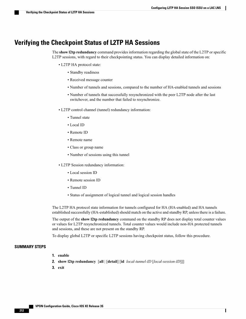
Verifying the Checkpoint Status of L2TP HA SessionsThe show l2tp redundancy command provides information regarding the global state of the L2TP or specificL2TP sessions, with regard to their checkpointing status. You can display detailed information on:
• L2TP HA protocol state:
• Standby readiness
• Received message counter
• Number of tunnels and sessions, compared to the number of HA-enabled tunnels and sessions
• Number of tunnels that successfully resynchronized with the peer L2TP node after the lastswitchover, and the number that failed to resynchronize.
• L2TP control channel (tunnel) redundancy information:
• Tunnel state
• Local ID
• Remote ID
• Remote name
• Class or group name
• Number of sessions using this tunnel
• L2TP Session redundancy information:
• Local session ID
• Remote session ID
• Tunnel ID
• Status of assignment of logical tunnel and logical session handles
The L2TP HA protocol state information for tunnels configured for HA (HA-enabled) and HA tunnelsestablished successfully (HA-established) should match on the active and standby RP, unless there is a failure.
The output of the show l2tp redundancy command on the standby RP does not display total counter valuesor values for L2TP resynchronized tunnels. Total counter values would include non-HA protected tunnelsand sessions, and these are not present on the standby RP.
To display global L2TP or specific L2TP sessions having checkpoint status, follow this procedure.
SUMMARY STEPS
1. enable2. show l2tp redundancy [all | [detail] [id local-tunnel-ID [local-session-ID]]]3. exit
VPDN Configuration Guide, Cisco IOS XE Release 3S212
Configuring L2TP HA Session SSO ISSU on a LAC LNSVerifying the Checkpoint Status of L2TP HA Sessions
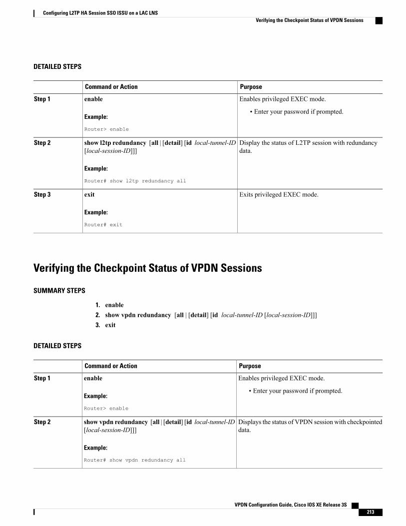
DETAILED STEPS
PurposeCommand or Action
Enables privileged EXEC mode.enableStep 1
Example:
Router> enable
• Enter your password if prompted.
Display the status of L2TP session with redundancydata.
show l2tp redundancy [all | [detail] [id local-tunnel-ID[local-session-ID]]]
Example:
Router# show l2tp redundancy all
Step 2
Exits privileged EXEC mode.exit
Example:
Router# exit
Step 3
Verifying the Checkpoint Status of VPDN Sessions
SUMMARY STEPS
1. enable2. show vpdn redundancy [all | [detail] [id local-tunnel-ID [local-session-ID]]]3. exit
DETAILED STEPS
PurposeCommand or Action
Enables privileged EXEC mode.enableStep 1
Example:
Router> enable
• Enter your password if prompted.
Displays the status of VPDN session with checkpointeddata.
show vpdn redundancy [all | [detail] [id local-tunnel-ID[local-session-ID]]]
Example:
Router# show vpdn redundancy all
Step 2
VPDN Configuration Guide, Cisco IOS XE Release 3S 213
Configuring L2TP HA Session SSO ISSU on a LAC LNSVerifying the Checkpoint Status of VPDN Sessions

PurposeCommand or Action
Exits privileged EXEC mode.exit
Example:
Router# exit
Step 3
Troubleshooting L2TP or VPDN Redundancy SessionsThere is extensive troubleshooting for L2TP or VPDN redundancy sessions. For example, if the standby RPdoes not initialize, the show l2tp redundancy command displays a warning message and will display notunnel or session information.
Router# show l2tp redundancy
L2TP HA support: Silent FailoverL2TP HA Status:Checkpoint Messaging on: FALSEStandby RP is up: TRUERecv'd Message Count: 0
No HA CC of Session data to display until Standby RP is up.You can use the debug l2tp redundancy or debug vpdn redundancy commands to display debug informationrelating to L2TP- or VPDN-checkpointing events or errors. Debug information includes:
• cf--L2TP redundancy checkpointing-facility events (cf-events)
• detail--L2TP redundancy details
• error--L2TP redundancy errors
• event--L2TP redundancy events
• fsm--L2TP redundancy fsm-events
• resync--L2TP redundancy resynchronizations
• rf--L2TP redundancy-facility events (rf-events)
To debug an L2TP or VPDN session having redundancy event errors, follow this procedure.
SUMMARY STEPS
1. enable2. debug {l2tp | vpdn} redundancy {cf | detail | error | event | fsm | resync | rf}3. exit
VPDN Configuration Guide, Cisco IOS XE Release 3S214
Configuring L2TP HA Session SSO ISSU on a LAC LNSTroubleshooting L2TP or VPDN Redundancy Sessions

DETAILED STEPS
PurposeCommand or Action
Enables privileged EXEC mode.enableStep 1
Example:
Router> enable
• Enter your password if prompted.
Displays debug information for VPDN session withredundancy data.
debug {l2tp | vpdn} redundancy {cf | detail | error |event | fsm | resync | rf}
Example:
Router# debug vpdn redundancy cf
Step 2
Exits privileged EXEC mode.exit
Example:
Router# exit
Step 3
Configuring L2TP HA SSO ISSU on a RADIUS ServerYou can configure L2TP HA SSO/ISSU on a RADIUS server, using the following RADIUS attribute-value(AV) pair:
cisco:cisco-avpair="vpdn:l2tp-silent-switchover=1"You can configure the L2TPHASSO/ISSU resynchronous parameter on a RADIUS server, using the followingRADIUS AV pair:
cisco:cisco-avpair="vpdn:l2tp-tunnel-resync-packet=<num>"
Configuration Examples for L2TP HA Session SSO ISSU on aLAC LNS
Example Configuring SSO on a Route ProcessorThis example shows how to configure SSO on a route processor:
Router# configure terminalRouter(config)# redundancyRouter (config-red)# mode ssoRouter (config-red)# end
VPDN Configuration Guide, Cisco IOS XE Release 3S 215
Configuring L2TP HA Session SSO ISSU on a LAC LNSConfiguring L2TP HA SSO ISSU on a RADIUS Server

Example Configuring L2TP High AvailabilityThis example shows how to configure L2TP SSO:
Router# configure terminalRouter(config)# l2tp sso enableRouter (config-red)# end
Examples Displaying L2TP Checkpoint Status
Example Displaying L2TP Redundancy InformationThe following example shows an L2TP redundancy information request:
Router# show l2tp redundancyL2TP HA support: Silent FailoverL2TP HA Status:Checkpoint Messaging on: TRUEStandby RP is up: TRUERecv'd Message Count: 189L2TP Tunnels: 2/2/2/0 (total/HA-enabled/HA-est/resync)L2TP Sessions: 20/20/20 (total/HA-enabled/HA-est)L2TP Resynced Tunnels: 2/0 (success/fail)Resync duration 0.63 secs (complete)
Example Displaying L2TP Redundancy Detail InformationThe following example shows an L2TP redundancy detail information request:
Router# show l2tp redundancy detail id 44233 2Local session ID : 2Remote session ID : 2Local CC ID : 44233Local UDP port : 1701Remote UDP port : 1701Waiting for VPDN application : NoWaiting for L2TP protocol : No
Example Displaying All L2TP Redundancy InformationThe following example shows an L2TP redundancy all-information request:
Router# show l2tp redundancy all
L2TP HA support: Silent FailoverL2TP HA Status:Checkpoint Messaging on: FALSEStandby RP is up: TRUERecv'd Message Count: 0L2TP Active Tunnels: 1/1/0 (total/HA-enabled/resync)L2TP Active Sessions: 1/1 (total/HA-enabled)L2TP Resynced Tunnels: 1/0 (success/fail)L2TP HA CC Check Point Status:State LocID RemID Remote Name Class/Group Num. Sessionsest 33003 26355 LAC-1 1 1L2TP HA Session Status:
VPDN Configuration Guide, Cisco IOS XE Release 3S216
Configuring L2TP HA Session SSO ISSU on a LAC LNSExample Configuring L2TP High Availability

LocID RemID TunID Waiting for Waiting forVPDN app? L2TP proto?
28017 10 33003 No No
Example Displaying L2TP Redundancy ID InformationThe following example shows how to limit the information displayed by providing a tunnel ID:
Router# show l2tp redundancy id 33003L2TP HA Session Status:LocID RemID TunID Waiting for Waiting for
VPDN app? L2TP proto?2 2 33003 No No
Example Displaying L2TP Redundancy Detail ID InformationThe following example shows how to limit the information displayed by providing a session ID:
Router# show l2tp redundancy detail id 33003 3Local session ID : 3Remote session ID : 3Local CC ID : 33003Local UDP port : 1701Remote UDP port : 1701Waiting for VPDN application : NoWaiting for L2TP protocol : No
Additional ReferencesRelated Documents
Document TitleRelated Topic
Cisco IOS Master Commands List, All ReleasesCisco IOS commands
Cisco IOS VPDN Command ReferenceVPDN commands
Layer 2 Tunnel Protocol Technology BriefLayer 2 Tunnel Protocol
Configuring Stateful Switchover moduleStateful switchover and high availability
http://www.cisco.com/en/US/docs/routers/asr1000/configuration/guide/chassis/issu.html
ISSU on Cisco ASR 1000 Series Routers
VPDN Technology Overview moduleVPDN technology overview
Standards
TitleStandard
--None
VPDN Configuration Guide, Cisco IOS XE Release 3S 217
Configuring L2TP HA Session SSO ISSU on a LAC LNSAdditional References
MIBs
MIBs LinkMIB
To locate and downloadMIBs for selected platforms,Cisco software releases, and feature sets, use CiscoMIB Locator found at the following URL:
http://www.cisco.com/go/mibs
None
RFCs
TitleRFC
Layer 2 Tunneling Protocol (L2TP)RFC 2661
Fail Over for Layer 2 Tunneling Protocol (L2TP)RFC 4591
Technical Assistance
LinkDescription
http://www.cisco.com/cisco/web/support/index.htmlThe Cisco Support and Documentation websiteprovides online resources to download documentation,software, and tools. Use these resources to install andconfigure the software and to troubleshoot and resolvetechnical issues with Cisco products and technologies.Access to most tools on the Cisco Support andDocumentation website requires a Cisco.com user IDand password.
Feature Information for L2TP HA Session SSO ISSU on a LACLNS
The following table provides release information about the feature or features described in this module. Thistable lists only the software release that introduced support for a given feature in a given software releasetrain. Unless noted otherwise, subsequent releases of that software release train also support that feature.
Use Cisco Feature Navigator to find information about platform support and Cisco software image support.To access Cisco Feature Navigator, go to www.cisco.com/go/cfn. An account on Cisco.com is not required.
VPDN Configuration Guide, Cisco IOS XE Release 3S218
Configuring L2TP HA Session SSO ISSU on a LAC LNSFeature Information for L2TP HA Session SSO ISSU on a LAC LNS

Table 14: Feature Information for L2TP HA Session SSO/ISSU on a LAC/LNS
Feature InformationReleasesFeature Name
Provides a generic SSO/ISSUmechanism for Layer 2 TunnelingProtocol (L2TP) on a LAC and aLNS.
This feature was introduced on theCisco ASR 1000 Series Routers.
The following commands wereintroduced by this feature: debugl2tp redundancy, debug vpdnredundancy, l2tp sso enable, l2tptunnel resync, show l2tpredundancy, show vpdnredundancy, sso enable.
In 2.3, support was added forscaling parameters for VPDNgroups and templates.
In 2.4, support was added forsupport for Multihop VPDN forVPDN tunnels and sessions.
Cisco IOS XE Release 2.2
Cisco IOS XE Release 2.3
Cisco IOS XE Release 2.4
L2TP HA Session SSO/ISSU on aLAC/LNS
VPDN Configuration Guide, Cisco IOS XE Release 3S 219
Configuring L2TP HA Session SSO ISSU on a LAC LNSFeature Information for L2TP HA Session SSO ISSU on a LAC LNS

VPDN Configuration Guide, Cisco IOS XE Release 3S220
Configuring L2TP HA Session SSO ISSU on a LAC LNSFeature Information for L2TP HA Session SSO ISSU on a LAC LNS

C H A P T E R 8L2TP Disconnect Cause Information
The L2TPDisconnect Cause Information feature adds support for additional Layer 2 Tunnel Protocol (L2TP)disconnect error codes using attribute-value (AV) pair 46 as specified by RFC 3145. Prior to the introductionof this feature, L2TP hosts could not exchange PPP disconnect error codes.
• Finding Feature Information, page 221
• Restrictions for L2TP Disconnect Cause Information, page 221
• Information About L2TP Disconnect Cause Information, page 222
• Additional References, page 224
• Feature Information for L2TP Disconnect Cause Information, page 225
Finding Feature InformationYour software release may not support all the features documented in this module. For the latest caveats andfeature information, see Bug Search Tool and the release notes for your platform and software release. Tofind information about the features documented in this module, and to see a list of the releases in which eachfeature is supported, see the feature information table.
Use Cisco Feature Navigator to find information about platform support and Cisco software image support.To access Cisco Feature Navigator, go to www.cisco.com/go/cfn. An account on Cisco.com is not required.
Restrictions for L2TP Disconnect Cause Information• This feature implements only error codes that are compliant with RFC 3145.
• If a router receives AV pair 46 with a nonsupported disconnect code it is mapped to code 0, indicatingthat no information is available.
VPDN Configuration Guide, Cisco IOS XE Release 3S 221

Information About L2TP Disconnect Cause Information
How L2TP Disconnect Cause Information WorksL2TP disconnect cause codes allow the devices functioning as L2TP hosts to exchange PPP-related disconnectcause information. Normally L2TP operation is isolated from details of the PPP session that is beingencapsulated. AV pair 46 PPP Disconnect Cause Code is used to exchange PPP-related disconnect causeinformation between L2TP hosts. The information can be translated to the appropriate authentication,authorization, and accounting (AAA) code and relayed to the remote RADIUS AAA server.
Benefits of L2TP Disconnect Cause InformationWhen L2TP service fails or session establishment is unsuccessful, PPP-specific disconnect informationprovides valuable information that can be used for troubleshooting or accounting purposes. The lack of thisinformation is a problem particularly when the L2TP hosts are not owned or managed by the same entities.The L2TP Disconnect Cause Information feature enables service providers to determine the specific failurereason, facilitating analysis and error correction.
L2TP Disconnect Cause Information CodesThe table below lists the supported L2TP disconnect cause codes from RFC 3145 and a brief description ofthe codes.
Table 15: L2TP Disconnect Cause Codes
DescriptionCode
Global Errors
No information available.
If a router receives AV pair 46 with anonsupported disconnect code, possibly fromanother vendor or a newer version of Ciscosoftware, it is mapped to this code.
Note
0
Administrative disconnect.1
Normal disconnection, Link Control Protocol (LCP)Terminate-Request sent.
Valid direction values are:
• 1--LCP Terminate-Request sent by the peerdevice.
• 2--LCP Terminate-Request sent by the localdevice.
3
VPDN Configuration Guide, Cisco IOS XE Release 3S222
L2TP Disconnect Cause InformationInformation About L2TP Disconnect Cause Information

DescriptionCode
LCP Errors
Finite State Machine (FSM) timeout error.5
No recognizable LCP packets were received.6
LCP link failure: Echo Request timeout.8
The peer has an unexpected endpoint-discriminatorfor an existing Multilink PPP (MLP) bundle.
9
Compulsory call-back required by a PPP peer wasrefused by the peer.
Valid direction values are:
• 1--Required by the local device; refused by thepeer device.
• 2--Required by the peer device; refused by thelocal device.
12
Authentication Errors
FSM timeout error.13
PPP authentication failed due to a bad hostname,password, or secret.
Valid direction values are:
• 1--Authentication of the peer’s identity by thelocal system failed.
• 2--Authentication of the local identity by thepeer system failed.
16
Network Control Protocol (NCP) Errors
FSM timeout error.17
No NCPs available (all disabled or rejected) or noNCPs went to Opened state. The Control ProtocolNumber can be zero only if neither peer has enabledNCPs.
18
VPDN Configuration Guide, Cisco IOS XE Release 3S 223
L2TP Disconnect Cause InformationL2TP Disconnect Cause Information Codes

Additional ReferencesRelated Documents
Document TitleRelated Topic
Cisco IOS Master Commands List, All ReleasesCisco IOS commands
VPDN Tunnel Management moduleInformation about configuring L2TP VPDN tunnels
Cisco IOS VPDN Command ReferenceVPDN commands
Standards
TitleStandard
--No new or modified standards are supported by thisfeature, and support for existing standards has notbeen modified by this feature.
MIBs
MIBs LinkMIB
To locate and downloadMIBs for selected platforms,Cisco software releases, and feature sets, use CiscoMIB Locator found at the following URL:
http://www.cisco.com/go/mibs
No new or modified MIBs are supported by thisfeature, and support for existing MIBs has not beenmodified by this feature.
RFCs
TitleRFC
L2TP Disconnect Cause InformationRFC 3145
VPDN Configuration Guide, Cisco IOS XE Release 3S224
L2TP Disconnect Cause InformationAdditional References

Technical Assistance
LinkDescription
http://www.cisco.com/cisco/web/support/index.htmlThe Cisco Support and Documentation websiteprovides online resources to download documentation,software, and tools. Use these resources to install andconfigure the software and to troubleshoot and resolvetechnical issues with Cisco products and technologies.Access to most tools on the Cisco Support andDocumentation website requires a Cisco.com user IDand password.
Feature Information for L2TP Disconnect Cause InformationThe following table provides release information about the feature or features described in this module. Thistable lists only the software release that introduced support for a given feature in a given software releasetrain. Unless noted otherwise, subsequent releases of that software release train also support that feature.
Use Cisco Feature Navigator to find information about platform support and Cisco software image support.To access Cisco Feature Navigator, go to www.cisco.com/go/cfn. An account on Cisco.com is not required.
Table 16: Feature Information for the L2TP Disconnect Cause Information Feature
Feature InformationReleasesFeature Name
This feature was introduced on theCisco ASR 1000 SeriesAggregation Services Routers.
The L2TP Disconnect CauseInformation feature adds supportfor additional Layer 2 TunnelProtocol (L2TP) disconnect errorcodes using attribute-value (AV)pair 46 as specified by RFC 3145.Prior to the introduction of thisfeature, L2TP hosts could notexchange PPP disconnect errorcodes.
No commands were introduced ormodified by this feature.
Cisco IOS XE Release 2.1L2TP Disconnect CauseInformation
VPDN Configuration Guide, Cisco IOS XE Release 3S 225
L2TP Disconnect Cause InformationFeature Information for L2TP Disconnect Cause Information

VPDN Configuration Guide, Cisco IOS XE Release 3S226
L2TP Disconnect Cause InformationFeature Information for L2TP Disconnect Cause Information

C H A P T E R 9Configuring the Managed IPv6 Layer 2 TunnelProtocol Network Server
This document describes how to enable the Managed IPv6 Layer 2 Tunnel Protocol Network Server feature.
• Finding Feature Information, page 227
• Prerequisites for Configuring the Managed IPv6 LNS, page 227
• Information About Configuring the Managed IPv6 LNS, page 228
• How to Configure the Managed LNS, page 230
• Configuration Examples for the Managed IPv6 Layer 2 Tunnel Protocol Network Server, page 248
• Additional References, page 254
• Feature Information for Configuring Managed IPv6 Layer 2 Tunnel Protocol Network Server, page255
Finding Feature InformationYour software release may not support all the features documented in this module. For the latest caveats andfeature information, see Bug Search Tool and the release notes for your platform and software release. Tofind information about the features documented in this module, and to see a list of the releases in which eachfeature is supported, see the feature information table.
Use Cisco Feature Navigator to find information about platform support and Cisco software image support.To access Cisco Feature Navigator, go to www.cisco.com/go/cfn. An account on Cisco.com is not required.
Prerequisites for Configuring the Managed IPv6 LNSFor the router to function as an LNS, you must enable Authentication, Authorization, and Accounting (AAA)on the Layer 2 Tunnel Protocol Network Server (LNS) and the Layer 2 Access Concentrator (LAC), byentering the aaanew-model global configuration command. For more information, see the “ Authentication,Authorization, and Accounting ” chapter in the Cisco IOS XE Security: Securing User Services ConfigurationGuide .
VPDN Configuration Guide, Cisco IOS XE Release 3S 227

Information About Configuring the Managed IPv6 LNS
L2TP Network ServerThe router can function as an LNS. The LNS is a peer to the LAC and sits on one side of an L2TP tunnel.The LNS routes packets to and from the LAC and a destination network. When the router functions as anLNS, you can configure the router to terminate the PPP sessions and route the client IP packets onto the ISPor corporate network toward their final destination (see the figure below). The router can use the ManagedIPv6 LNS feature to terminate L2TP sessions from the LAC and place each session into the appropriate IPv6VRF instance based on the VRF applied to the virtual template interface or alternatively, based on the VRFreceived for the user through AAA. The router then routes each session within the VRF to the destinationnetwork.
Figure 10: Terminating and Forwarding Sessions from the LAC
Tunnel AccountingThe tunnel accounting feature enhances AAA accounting by adding the ability to include tunnel-relatedstatistics in the RADIUS information. Before you can collect tunnel usage information, you must configurethe following attributes on the RADIUS server:
• Acct-Tunnel-Connection—Specifies the identifier assigned to the tunnel session. This attribute and theTunnel-Client-Endpoint and Tunnel-Server-Endpoint attributes provide a way to uniquely identify atunnel session for auditing purposes.
• Acct-Tunnel-Packets-Lost—Specifies the number of packets lost on a given link.
The table below describes the values for the Acct-Status-Type attribute that support tunnel accounting on theRADIUS server.
VPDN Configuration Guide, Cisco IOS XE Release 3S228
Configuring the Managed IPv6 Layer 2 Tunnel Protocol Network ServerInformation About Configuring the Managed IPv6 LNS

Table 17: Acct-Status-Type Values for RADIUS Tunnel Accounting
DescriptionValueAcct-Status-Type Values
Marks the rejection of theestablishment of a new link in anexisting tunnel.
14Tunnel-Link-Reject
Marks the creation of a tunnel linkwithin an L2TP tunnel that carriesmultiple links.
12Tunnel-Link-Start
Marks the destruction of a tunnellink within an L2TP tunnel thatcarries multiple links.
13Tunnel-Link-Stop
Marks the rejection of theestablishment of a tunnel withanother device.
11Tunnel-Reject
Marks the establishment of a tunnelwith another device.
9Tunnel-Start
Marks the destruction of a tunnelto or from another device.
10Tunnel-Stop
For more information about the RADIUS tunnel accounting attributes or the Acct-Status-Type values thatsupport RADIUS tunnel accounting, see RFC 2867, RADIUS Accounting Modifications for Tunnel ProtocolSupport.
For information about RADIUS accounting attributes supported on the Cisco ASR 1000 Series AggregationServices Routers, see the “RADIUS Attributes” chapter in the Cisco IOS XE Security Configuration Guide:Securing User Services.
For more information on configuring RADIUS, see your RADIUS user documentation.
VPDN Configuration Guide, Cisco IOS XE Release 3S 229
Configuring the Managed IPv6 Layer 2 Tunnel Protocol Network ServerTunnel Accounting

How to Configure the Managed LNS
Configuring a VRF on the LNS
SUMMARY STEPS
1. enable2. configure terminal3. vrf definition vrf-name4. rd route-distinguisher5. address-family {ipv4|ipv6}6. route-target {import|export|both} route-target-ext-community7. exit-address-family8. address-family {ipv4|ipv6}9. route-target {import|export|both} route-target-ext-community10. end11. show ipv6 route vrf vrf-name
DETAILED STEPS
PurposeCommand or Action
Enters privileged EXEC mode.enable
Example:
Router> enable
Step 1
Enters global configuration mode.configure terminal
Example:
Router# configure terminal
Step 2
Configures a VRF routing table and enters VRF configuration mode.vrf definition vrf-nameStep 3
Example:
Router(config)# vrf definition vrf1
• The vrf-nameargument is the name of the VRF.
Creates routing and forwarding tables for a VRF.rd route-distinguisherStep 4
Example:
Router(config-vrf)# rd 100:1
• The route-distinguisher argument adds an 8-byte value to an IPv4prefix to create a VPN IPv4 prefix. You can enter a route distinguisherin either of these formats:
VPDN Configuration Guide, Cisco IOS XE Release 3S230
Configuring the Managed IPv6 Layer 2 Tunnel Protocol Network ServerHow to Configure the Managed LNS

PurposeCommand or Action
• 16-bit autonomous system number (ASN): your 32-bit numberFor example, 101:3.
• 32-bit IP address: your 16-bit number For example,192.168.122.15:1.
Enters VRF address family configuration mode to specify an address familyfor a VRF.
address-family {ipv4|ipv6}
Example:
Router(config-vrf) address-familyipv6
Step 5
• The ipv4 keyword specifies an IPv4 address family for a VRF.
• The ipv6 keyword specifies an IPv6 address family for a VRF.
Creates a route-target extended community for a VRF.route-target {import|export|both}route-target-ext-community
Step 6
• The import keyword imports routing information from the target VPNextended community.
Example:
Router(config-vrf-af) route-targetboth 100:2
• The export keyword exports routing information to the target VPNextended community.
• The both keyword imports both import and export routing informationto the target VPN extended community.
• The route-target-ext-community argument adds the route-targetextended community attributes to the VRF list of import, export, orboth (import and export) route-target extended communities.
Exits VRF address family configuration mode and enters VRF configurationmode.
exit-address-family
Example:
Router(config-vrf-af)#exit-address-family
Step 7
Enters VRF address family configuration mode to specify an address familyfor a VRF.
address-family {ipv4|ipv6}
Example:
Router(config-vrf) address-familyipv6
Step 8
• The ipv4 keyword specifies an IPv4 address family for a VRF.
• The ipv6 keyword specifies an IPv6 address family for a VRF.
Creates a route-target extended community for a VRF.route-target {import|export|both}route-target-ext-community
Step 9
• The import keyword specifies to import routing information from thetarget VPN extended community.
Example:
Router(config-vrf-af)# route-targetboth 100:3
• The export keyword specifies to export routing information to thetarget VPN extended community.
• The both keyword specifies to import both import and export routinginformation to the target VPN extended community.
VPDN Configuration Guide, Cisco IOS XE Release 3S 231
Configuring the Managed IPv6 Layer 2 Tunnel Protocol Network ServerConfiguring a VRF on the LNS

PurposeCommand or Action
• The route-target-ext-community argument adds the route-targetextended community attributes to the VRF list of import, export, orboth (import and export) route-target extended communities.
• Enter the route-target command one time for each target community.
Exits VRF address family configuration mode and returns to privilegedEXEC mode.
end
Example:
Router(config-vrf-af)# end
Step 10
Displays the IPv6 routing table associated with a VRF.show ipv6 route vrf vrf-name
Example:
Router# show ipv6 route vrf vrf1
Step 11
Configuring a Virtual Template Interface
SUMMARY STEPS
1. enable2. configure terminal3. interface virtual-template number4. vrf forwarding name5. ppp authentication chap6. end7. show interfaces virtual-access number [configuration]8. debug ppp chap9. debug ppp negotiation10. debug ppp negotiation chap
DETAILED STEPS
PurposeCommand or Action
Enters privileged EXEC mode.enable
Example:
Router> enable
Step 1
VPDN Configuration Guide, Cisco IOS XE Release 3S232
Configuring the Managed IPv6 Layer 2 Tunnel Protocol Network ServerConfiguring a Virtual Template Interface

PurposeCommand or Action
Enters global configuration mode.configure terminal
Example:
Router# configure terminal
Step 2
Creates a virtual template interface and enters interfaceconfiguration mode.
interface virtual-template number
Example:
Router(config)# interface virtual-template1
Step 3
(Optional) Maps the virtual template interface to a VRF routingtable.
vrf forwarding name
Example:
Router(config-if)# vrf forwarding vpn-1
Step 4
If the VRF assignment is received via the RADIUSserver, then this step is not required.
Note
Enables CHAP authentication on the virtual template interface,which is applied to virtual access interfaces (VAI).
ppp authentication chap
Example:
Router(config-if)# ppp authentication chap
Step 5
Exits interface configurationmode and returns to privileged EXECmode.
end
Example:
Router(config-if)# end
Step 6
Displays status, traffic data, and configuration information aboutthe VAI you specify.
show interfaces virtual-access number[configuration]
Example:
Router# show interfaces virtual-accessnumber [configuration]
Step 7
Displays authentication protocol messages for ChallengeAuthentication Protocol (CHAP) packet exchanges.
debug ppp chap
Example:
Router# debug ppp chap
Step 8
• This command is useful when a CHAP authentication failureoccurs due to a configuration mismatch between devices.Verifying and correcting any username and passwordmismatch resolves the problem.
VPDN Configuration Guide, Cisco IOS XE Release 3S 233
Configuring the Managed IPv6 Layer 2 Tunnel Protocol Network ServerConfiguring a Virtual Template Interface

PurposeCommand or Action
Displays information on traffic and exchanges in an internetworkimplementing PPP.
debug ppp negotiation
Example:
Router# debug ppp negotiation
Step 9
Deciphers a CHAP negotiation problem due to a connectivityproblem between a Cisco and non-Cisco device.
debug ppp negotiation chap
Example:
Router# debug ppp negotiation chap
Step 10
Assigning a VRF via the RADIUS Server
SUMMARY STEPS
1. enable2. configure terminal3. aaa authorization configuration method-name group group-name4. ipv6 dhcp pool pool-name5. prefix-delegation aaa [method-listmethod-list]6. dns-server ipv6-address7. exit8. interface virtual-template number9. ipv6 nd prefix framed-ipv6-prefix10. ipv6 dhcp server pool-name rapid-commit11. end
DETAILED STEPS
PurposeCommand or Action
Enters privileged EXEC mode.enable
Example:
Router> enable
Step 1
VPDN Configuration Guide, Cisco IOS XE Release 3S234
Configuring the Managed IPv6 Layer 2 Tunnel Protocol Network ServerAssigning a VRF via the RADIUS Server

PurposeCommand or Action
Enters global configuration mode.configure terminal
Example:
Router# configure terminal
Step 2
Downloads configuration information from the AAAserver using RADIUS.
aaa authorization configuration method-namegroup group-name
Example:
Router(config)# aaa authorization configurationDHCPv6-PD group DHCPv6-PD-RADIUS
Step 3
Configures a DHCP for IPv6 configuration informationpool and enters DHCP for IPv6 pool configuration mode.
ipv6 dhcp pool pool-name
Example:
Router(config)# ipv6 dhcp pool DHCPv6-PD
Step 4
Specifies that prefixes are to be acquired from AAAservers.
prefix-delegation aaa [method-listmethod-list]
Example:
Router(config-dhcpv6)# prefix-delegation aaamethod-list DHCPv6-PD
Step 5
Specifies the Domain Name System (DNS) IPv6 serversavailable to a DHCP for IPv6 client.
dns-server ipv6-address
Example:
Router(config-dhcpv6)# dns-server2001:0DB8:3000:3000::42
Step 6
Exits DHCP for IPv6 pool configuration mode and entersglobal configuration mode.
exit
Example:
Router(config-dhcpv6)# exit
Step 7
Creates a virtual template interface that can be configuredand applied dynamically in creating VAIs, and entersinterface configuration mode.
interface virtual-template number
Example:
Router(config)# interface virtual-template 1
Step 8
Adds the prefix in a received RADIUS framed IPv6 prefixattribute to the interface's neighbor discovery prefix queue.
ipv6 nd prefix framed-ipv6-prefix
Example:
Router(config-if)# ipv6 nd prefixframed-ipv6-prefix
Step 9
VPDN Configuration Guide, Cisco IOS XE Release 3S 235
Configuring the Managed IPv6 Layer 2 Tunnel Protocol Network ServerAssigning a VRF via the RADIUS Server

PurposeCommand or Action
Enables DHCPv6 on an interface.ipv6 dhcp server pool-name rapid-commit
Example:
Router(config-if)# ipv6 dhcp server DHCPv6-PDrapid-commit
Step 10
Exits interface configuration mode and returns toprivileged EXEC mode.
end
Example:
Router(config-if)# end
Step 11
Configuring the LNS to Initiate and Receive L2TP Traffic
SUMMARY STEPS
1. enable2. configure terminal3. vpdn enable4. vpdn-group group-name5. accept-dialin6. protocol 12tp7. virtual-template template-number8. exit9. terminate-from hostname hostname10. end
DETAILED STEPS
PurposeCommand or Action
Enters privileged EXEC mode.enable
Example:
Router> enable
Step 1
Enters global configuration mode.configure terminal
Example:
Router# configure terminal
Step 2
VPDN Configuration Guide, Cisco IOS XE Release 3S236
Configuring the Managed IPv6 Layer 2 Tunnel Protocol Network ServerConfiguring the LNS to Initiate and Receive L2TP Traffic

PurposeCommand or Action
Enables VPDN networking on the router and informs the routerto look for tunnel definitions in a local database and on a remoteauthorization server (home gateway) if one is present.
vpdn enable
Example:
Router(config)# vpdn enable
Step 3
Defines a local group name for which you can assign otherVPDN variables.
vpdn-group group-name
Example:
Router(config)# vpdn-group group1
Step 4
• Enters VPDN group configuration mode.
Configures the LNS to accept tunneled PPP connections fromthe LAC and creates an accept-dialin VPDN subgroup.
accept-dialin
Example:
Router(config-vpdn)# accept-dialin
Step 5
• Enters accept dial-in VPDN subgroup configurationmode.
Specifies the Layer 2 Tunnel Protocol.protocol 12tp
Example:
Router(config-vpdn-acc-in)# protocol 12tp
Step 6
Specifies the virtual template to be used to clone VAIs.virtual-template template-number
Example:
Router(config-vpdn-acc-in)# virtual-template1
Step 7
Returns to VPDN group configuration mode.exit
Example:
Router(config-vpdn-acc-in)# exit
Step 8
Specifies the hostname of the remote LAC that is requiredwhen accepting a VPDN tunnel.
terminate-from hostname hostname
Example:
Router(config-vpdn)# terminate-from hostnamelac1-vpn1
Step 9
Exits VPDN configuration mode and returns to privilegedEXEC mode.
end
Example:
Router(config-vpdn)# end
Step 10
VPDN Configuration Guide, Cisco IOS XE Release 3S 237
Configuring the Managed IPv6 Layer 2 Tunnel Protocol Network ServerConfiguring the LNS to Initiate and Receive L2TP Traffic

Limiting the Number of Sessions per Tunnel
SUMMARY STEPS
1. enable2. configure terminal3. vpdn-group group-name4. accept-dialin5. protocol 12tp6. virtual-template template-number7. exit8. terminate-from hostname host-name9. session-limit limit-number10. exit
DETAILED STEPS
PurposeCommand or Action
Enters privileged EXEC mode.enable
Example:
Router> enable
Step 1
Enters global configuration mode.configure terminal
Example:
Router# configure terminal
Step 2
Defines a local group name for which you can assign otherVPDN variables.
vpdn-group group-name
Example:
Router(config)# vpdn-group group1
Step 3
• Enters VPDN group configuration mode.
Configures the LNS to accept tunneled PPP connectionsfrom the LAC and creates an accept-dialin VPDN subgroup.
accept-dialin
Example:
Router(config-vpdn)# accept-dialin
Step 4
• Enters accept dial-in VPDN subgroup configurationmode.
Specifies the Layer 2 Tunnel Protocol.protocol 12tp
Example:
Router(config-vpdn-acc-in)# protocol 12tp
Step 5
VPDN Configuration Guide, Cisco IOS XE Release 3S238
Configuring the Managed IPv6 Layer 2 Tunnel Protocol Network ServerLimiting the Number of Sessions per Tunnel

PurposeCommand or Action
Specifies the virtual template to be used to clone VAIs.virtual-template template-number
Example:
Router(config-vpdn-acc-in)# virtual-template1
Step 6
Returns to VPDN group configuration mode.exit
Example:
Router(config-vpdn-acc-in)# exit
Step 7
Specifies the hostname of the remote LAC that is requiredwhen accepting a VPDN tunnel.
terminate-from hostname host-name
Example:
Router(config-vpdn)# terminate-from hostnametest_LAC
Step 8
Specifies the maximum number of sessions per tunnel.session-limit limit-number
Example:
Router(config-vpdn)# session-limit 100
Step 9
Exits VPDN configuration mode and returns to privilegedEXEC mode.
exit
Example:
Router(config-vpdn)# exit
Step 10
VPDN Configuration Guide, Cisco IOS XE Release 3S 239
Configuring the Managed IPv6 Layer 2 Tunnel Protocol Network ServerLimiting the Number of Sessions per Tunnel

Configuring RADIUS Attribute Accept or Reject Lists
SUMMARY STEPS
1. enable2. configure terminal3. aaa authentication ppp default group group-name4. aaa authorization network group group group-name5. aaa group server radius group-name6. server-private ip-address [acct-portport-number][timeoutseconds] [retransmitretries] [keystring]7. authorization [accept|reject] list-name8. exit9. radius-server attribute list listname10. attribute value1 [value2 [value3...]]11. end12. show accounting
DETAILED STEPS
PurposeCommand or Action
Enters privileged EXEC mode.enable
Example:
Router> enable
Step 1
Enters global configuration mode.configure terminal
Example:
Router# configure terminal
Step 2
Specifies one or more AAA authentication methods for use on serialinterfaces running PPP.
aaa authentication ppp default groupgroup-name
Example:
Router(config)# aaa authentication pppdefault group radius_authen1
Step 3
Sets the parameters that restrict network access to the user.aaa authorization network group groupgroup-name
Step 4
Example:
Router(config)# aaa authorization networkgroup group radius_authen1
VPDN Configuration Guide, Cisco IOS XE Release 3S240
Configuring the Managed IPv6 Layer 2 Tunnel Protocol Network ServerConfiguring RADIUS Attribute Accept or Reject Lists

PurposeCommand or Action
Groups different RADIUS server hosts into distinct lists and distinctmethods and enters server group RADIUS configuration mode.
aaa group server radius group-name
Example:
Router(config)# aaa group server radiusVPDN-Group
Step 5
Configures the IP address of the private RADIUS server for the groupserver.
server-private ip-address[acct-portport-number][timeoutseconds][retransmitretries] [keystring]
Step 6
• The ip-addressargument specifies the IP address of the privateRADIUS server host.
Example:
Router(config-sg-radius)# server-private• (Optional) The port-numberargument specifies the UDPdestination port for accounting requests.10.1.1.2 acct-port 0 timeout 7 retransmit
3 key cisco1 • (Optional) The seconds argument specifies the timeout value(1 to 1000).
• (Optional) The retriesargument specifies the number of timesa RADIUS request is re-sent to a server, if that server is notresponding or responding slowly.
• The string argument specifies the authentication and encryptionkey for all RADIUS communications between the router andthe RADIUS server.
Specifies a filter for the attributes that are returned in anAccess-Accept packet from the RADIUS server.
authorization [accept|reject] list-name
Example:
Router(config-sg-radius)# authorizationaccept vpn1-autho-list
Step 7
• The accept keyword indicates that all attributes will be rejectedexcept the attributes specified in the listname argument.
• The reject keyword indicates that all attributes will be acceptedexcept for the attributes specified in the listname argument andall standard attributes.
Exits server group RADIUS configuration mode and enters globalconfiguration mode.
exit
Example:
Router(config-sg-radius)# exit
Step 8
Defines the list name given to the set of attributes defined using theattribute command and enters RADIUS attribute list configurationmode.
radius-server attribute list listname
Example:
Router(config)# radius-server attributelist vpn1-autho-list
Step 9
• Define the listname argument to be the same as you defined itin step 7.
Adds attributes to the configured accept or reject list.attribute value1 [value2 [value3...]]Step 10
VPDN Configuration Guide, Cisco IOS XE Release 3S 241
Configuring the Managed IPv6 Layer 2 Tunnel Protocol Network ServerConfiguring RADIUS Attribute Accept or Reject Lists

PurposeCommand or Action
Example:
Router(config-radius-attrl)# attribute26,200
• You can use this command multiple times to add attributes toan accept or reject list.
Exits RADIUS attribute list configuration mode and returns toprivileged EXEC mode.
end
Example:
Router(config-radius-attrl)# end
Step 11
Displays accounting records for users currently logged in.show accountingStep 12
Example:
Router# show accounting
• Displays active accountable events on the network and helpscollect information in the event of a data loss on the accountingserver.
Configuring AAA Accounting Using Named Method Lists
System accounting does not use namedmethod lists. For system accounting you can define only the defaultmethod list. For more information, see the “Configuring Accounting ” chapter in the Cisco IOSXE SecurityConfiguration Guide: Securing User Services.
Note
SUMMARY STEPS
1. enable2. configure terminal3. aaa accounting network list-name start-stop group radius4. line [aux | console| vty] [line-number]5. accounting {arap|commandslevel|connection|exec|resource} [default | list-name]6. end7. debug aaa accounting
VPDN Configuration Guide, Cisco IOS XE Release 3S242
Configuring the Managed IPv6 Layer 2 Tunnel Protocol Network ServerConfiguring AAA Accounting Using Named Method Lists

DETAILED STEPS
PurposeCommand or Action
Enters privileged EXEC mode.enable
Example:
Router> enable
Step 1
Enters global configuration mode.configure terminal
Example:
Router# configure terminal
Step 2
Creates an accounting method list and enablesaccounting.
aaa accounting network list-name start-stop groupradius
Example:
Router(config)# aaa accounting network methodliststart-stop group radius
Step 3
Enters line configuration mode for the line to whichyou want to apply the accounting method list.
line [aux | console| vty] [line-number]
Example:
Router(config)# line console 0
Step 4
Applies the accounting method list to a line or a setof lines.
accounting{arap|commandslevel|connection|exec|resource} [default| list-name]
Step 5
Example:
Router(config-line)# accounting commands 15 list1
Exits line configurationmode and returns to privilegedEXEC mode.
end
Example:
Router(config-line)# end
Step 6
Displays information on accountable events as theyoccur.
debug aaa accounting
Example:
Router# debug aaa accounting
Step 7
VPDN Configuration Guide, Cisco IOS XE Release 3S 243
Configuring the Managed IPv6 Layer 2 Tunnel Protocol Network ServerConfiguring AAA Accounting Using Named Method Lists

Configuring RADIUS Tunnel Authentication Method Lists on the LNS
SUMMARY STEPS
1. enable2. configure terminal3. aaa authorization network list-name method1 [method2...]4. vpdn tunnel authorization network lmethod-ist-name method1 [method2...]5. vpdn tunnel authorization virtual-template vtemplate-number6. vpdn tunnel authorization password dummy-password7. debug aaa authorization
DETAILED STEPS
PurposeCommand or Action
Enters privileged EXEC mode.enable
Example:
Router> enable
Step 1
Enters global configuration mode.configure terminal
Example:
Router# configure terminal
Step 2
Sets parameters that restrict user access to a network.aaa authorization network list-namemethod1[method2...]
Step 3
• The list-name argument is a character string used to name the listof authentication methods tried when a user logs in.
Example:
Router(config)# aaa authorizationnetwork mymethodlist group VPDN-Group
• group radius: Uses the list of all RADIUS servers forauthentication.
• group group-name: Uses a subset of RADIUS servers forauthentication as defined by the aaa group server radius command.
• if-authenticated: Succeeds if user has been successfullyauthenticated.
• local: Uses the local username database for authentication.
• none: Uses no authentication.
The method list is only for VPDN tunnel authorization andtermination, not for domain and Digital Number IdentificationService (DNIS) authorization. Therefore, the method list appliesonly on the tunnel terminator device - the LAC for dialoutsessions and the LNS for dialin sessions.
Note
VPDN Configuration Guide, Cisco IOS XE Release 3S244
Configuring the Managed IPv6 Layer 2 Tunnel Protocol Network ServerConfiguring RADIUS Tunnel Authentication Method Lists on the LNS

PurposeCommand or Action
Specifies the AAA method list to use for VPDN remote tunnelhostname-based authorization.
vpdn tunnel authorization networklmethod-ist-name method1 [method2...]
Step 4
Example:
Router(config)# vpdn tunnelauthorization network mymethodlist
• If you do not specify a method list (including a default method list)by using the vpdn tunnel authorization network command, localauthorization occurs by using the local VPDN group configuration.
Specifies the default virtual template interface used to clone a VAI.vpdn tunnel authorization virtual-templatevtemplate-number
Step 5
• If you do not specify a virtual template interface in the local VPDNgroup configuration or in a remote RADIUS configuration, thenthe default virtual template interface is used.Example:
Router(config)# vpdn tunnelauthorization virtual-template 10
Specifies the password to use for the RADIUS authorization request toretrieve the tunnel configuration based on the remote tunnel hostname.
vpdn tunnel authorization passworddummy-password
Example:
Router(config)# vpdn tunnelauthorization password mypassword
Step 6
Displays information on AAA authorization.debug aaa authorization
Example:
Router# debug aaa authorization
Step 7
Configuring the LNS for RADIUS Tunnel AuthenticationPerform the following tasks to configure LNS for RADIUS Tunnel Authentication:
Cisco ASR 1000 Series Aggregation Services Routers supports L2TP tunnel authorization. However,RADIUS does not provide attributes for such parameter values as L2TP tunnel timeouts, L2TP tunnelhello intervals, and L2TP tunnel receive window size. When the Cisco ASR 1000 Series AggregationServices Router does not receive a RADIUS attribute for a parameter, the router uses the default value.
Note
Configuring RADIUS Tunnel Authentication Method Lists on the LNSTo configure method lists on the LNS for RADIUS tunnel authentication, perform the following task.
VPDN Configuration Guide, Cisco IOS XE Release 3S 245
Configuring the Managed IPv6 Layer 2 Tunnel Protocol Network ServerConfiguring the LNS for RADIUS Tunnel Authentication

SUMMARY STEPS
1. enable2. configure terminal3. aaa authorization network list-name method1 [method2...]4. vpdn tunnel authorization network method- list-name5. vpdn tunnel authorization virtual-template vtemplate-number6. vpdn tunnel authorization password dummy-password7. end8. debug aaa authorization
DETAILED STEPS
PurposeCommand or Action
Enters privileged EXEC mode.enable
Example:
Router> enable
Step 1
Enters global configuration mode.configure terminal
Example:
Router# configure terminal
Step 2
Sets parameters that restrict user access to a networkaaa authorization network list-namemethod1 [method2...]
Step 3
• Thelist-nameargument is a character string used to name the list ofauthentication methods tried when a user logs in.
Example:
Router(config)# aaa authorizationnetwork mymethodlist group VPDN-Group
• groupradius—Uses the list of all RADIUS servers forauthentication.
• groupgroup-name—Uses a subset of RADIUS servers forauthentication as defined by the aaagroupserverradiuscommand.
• if-authenticated—Succeeds if user has been successfullyauthenticated.
• local—Uses the local username database for authentication.
• none—Uses no authentication.
The method list is only for VPDN tunnel authorization andtermination, not for domain and Digital Number IdentificationService (DNIS) authorization. Therefore, the method list appliesonly on the tunnel terminator device—the LAC for dialout sessionsand the LNS for dialin sessions.
Note
VPDN Configuration Guide, Cisco IOS XE Release 3S246
Configuring the Managed IPv6 Layer 2 Tunnel Protocol Network ServerConfiguring RADIUS Tunnel Authentication Method Lists on the LNS

PurposeCommand or Action
Specifies the AAA method list to use for VPDN remote tunnelhostname-based authorization.
vpdn tunnel authorization networkmethod- list-name
Step 4
Example:
Router(config)# vpdn tunnelauthorization network mymethodlist
• If you do not specify a method list (including a default method list)by using the vpdntunnelauthorizationnetwork command, localauthorization occurs by using the local VPDN group configuration.
Specifies the default virtual template interface used to clone a VAI.vpdn tunnel authorizationvirtual-template vtemplate-number
Step 5
• If you do not specify a virtual template interface in the local VPDNgroup configuration or in a remote RADIUS configuration, then thedefault virtual template interface is used.Example:
Router(config)# vpdn tunnelauthorization virtual-template 10 The vpdntunnelauthorizationvirtual-template command is
applicable only on the LNS.Note
Specifies the password to use for the RADIUS authorization request toretrieve the tunnel configuration based on the remote tunnel hostname.
vpdn tunnel authorization passworddummy-password
Step 6
Example:
Router(config)# vpdn tunnelauthorization password mypassword
• By default, the password is cisco, but you can configure a differentpassword.
The vpdntunnelauthorizationpassword command is applicableon both the LAC and LNS.
Note
Exits global configuration mode and returns to privileged EXEC mode.end
Example:
Router(config)# end
Step 7
Displays information on AAA authorization.debug aaa authorization
Example:
Router# debug aaa authorization
Step 8
VPDN Configuration Guide, Cisco IOS XE Release 3S 247
Configuring the Managed IPv6 Layer 2 Tunnel Protocol Network ServerConfiguring RADIUS Tunnel Authentication Method Lists on the LNS

Configuring AAA Authentication Methods
SUMMARY STEPS
1. enable2. configure terminal3. aaa new-model4. Configure RADIUS security protocol parameters. For more information about RADIUS, see the
“Configuring RADIUS” chapter in the Cisco IOSXE Security Configuration Guide: Securing User Services.
5. aaa authentication6. Apply the authentication method lists to an interface, a line, or a set of lines as required. For more
information about authentication method lists, see the “Configuring Authentication” chapter in the CiscoIOS XE Security Configuration Guide: Securing User Services .
7. end
DETAILED STEPS
Step 1 enableStep 2 configure terminalStep 3 aaa new-model
Enter this command in global configuration mode to enable AAA.
Step 4 Configure RADIUS security protocol parameters. For more information about RADIUS, see the “Configuring RADIUS”chapter in the Cisco IOS XE Security Configuration Guide: Securing User Services .
Step 5 aaa authenticationEnter this command to define the authentication method lists.
Step 6 Apply the authentication method lists to an interface, a line, or a set of lines as required. For more information aboutauthentication method lists, see the “Configuring Authentication” chapter in the Cisco IOS XE Security ConfigurationGuide: Securing User Services .
Step 7 end
Configuration Examples for the Managed IPv6 Layer 2 TunnelProtocol Network Server
Example Managed IPv6 LNS ConfigurationThe following example shows how to configure Managed IPv6 LNS features on the router. In this example,the router terminates the tunnel from the LAC and associates the VRFs with the interfaces and the virtual
VPDN Configuration Guide, Cisco IOS XE Release 3S248
Configuring the Managed IPv6 Layer 2 Tunnel Protocol Network ServerConfiguring AAA Authentication Methods

template interfaces. This configuration also shows how to configure RADIUS attribute screening and AAAaccounting for the VRFs.
!!vrf definition Mgmt-intf!address-family ipv4exit-address-family!address-family ipv6exit-address-family!vrf definition user_vrf1rd 1:1route-target export 1:1route-target import 1:1!address-family ipv6exit-address-family!logging buffered 10000000enable password lab!aaa new-model!!aaa group server radius radius_authen1server-private 10.1.1.2 acct-port 0 timeout 7 retransmit 3 key cisco1ip radius source-interface Loopback20000!aaa authentication login default noneaaa authentication ppp default group radius_authen1aaa authorization network default group radius_authen1aaa authorization configuration DHCPv6-PD group radius_authen1!!!!!aaa session-id commonaaa policy interface-config allow-subinterfaceppp hold-queue 80000clock timezone EST -5 0ip source-routeno ip gratuitous-arps!!!!!!!no ip domain lookupip host mcp-matrix 10.0.0.2ip host mcp-sun-2 10.0.0.2!!ipv6 unicast-routingipv6 dhcp binding track pppipv6 dhcp pool ipv6_dhcp_pool1prefix-delegation aaa method-list DHCPv6-PD!!!!multilink bundle-name authenticatedvpdn enable!vpdn-group VPDN_LNS1accept-dialin
VPDN Configuration Guide, Cisco IOS XE Release 3S 249
Configuring the Managed IPv6 Layer 2 Tunnel Protocol Network ServerExample Managed IPv6 LNS Configuration

protocol l2tpvirtual-template 1terminate-from hostname test_LAC1source-ip 10.0.0.2local name test_LNS1l2tp tunnel password 0 tunnel1l2tp tunnel receive-window 100l2tp tunnel timeout no-session 30l2tp tunnel retransmit retries 7l2tp tunnel retransmit timeout min 2!!no virtual-template snmp!!!!!!!!!username asifp1@test1 password 0 hello1!redundancynotification-timer 30000mode none!!!!!ip tftp source-interface GigabitEthernet 0!!!!!!!!interface Loopback1no ip address!interface Loopback20000ip address 209.165.202.131 255.255.255.224!interface GigabitEthernet1/1/0mac-address 8888.8888.8888no ip addressload-interval 30negotiation autohold-queue 4096 inhold-queue 4096 out!interface GigabitEthernet1/1/0.1encapsulation dot1Q 3ip address 209.165.202.132 255.255.255.224!interface GigabitEthernet1/1/1mac-address 4444.4444.4444no ip addressload-interval 30no negotiation autohold-queue 4096 inhold-queue 4096 out!interface GigabitEthernet1/1/1.1vrf forwarding user_vrf1encapsulation dot1Q 2ipv6 address 12::1/72!interface GigabitEthernet1/1/2
VPDN Configuration Guide, Cisco IOS XE Release 3S250
Configuring the Managed IPv6 Layer 2 Tunnel Protocol Network ServerExample Managed IPv6 LNS Configuration
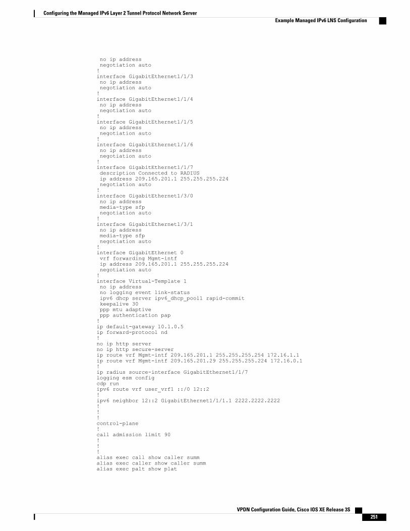
no ip addressnegotiation auto!interface GigabitEthernet1/1/3no ip addressnegotiation auto!interface GigabitEthernet1/1/4no ip addressnegotiation auto!interface GigabitEthernet1/1/5no ip addressnegotiation auto!interface GigabitEthernet1/1/6no ip addressnegotiation auto!interface GigabitEthernet1/1/7description Connected to RADIUSip address 209.165.201.1 255.255.255.224negotiation auto!interface GigabitEthernet1/3/0no ip addressmedia-type sfpnegotiation auto!interface GigabitEthernet1/3/1no ip addressmedia-type sfpnegotiation auto!interface GigabitEthernet 0vrf forwarding Mgmt-intfip address 209.165.201.1 255.255.255.224negotiation auto!interface Virtual-Template 1no ip addressno logging event link-statusipv6 dhcp server ipv6_dhcp_pool1 rapid-commitkeepalive 30ppp mtu adaptiveppp authentication pap!ip default-gateway 10.1.0.5ip forward-protocol nd!no ip http serverno ip http secure-serverip route vrf Mgmt-intf 209.165.201.1 255.255.255.254 172.16.1.1ip route vrf Mgmt-intf 209.165.201.29 255.255.255.224 172.16.0.1!ip radius source-interface GigabitEthernet1/1/7logging esm configcdp runipv6 route vrf user_vrf1 ::/0 12::2!ipv6 neighbor 12::2 GigabitEthernet1/1/1.1 2222.2222.2222!!!control-plane!call admission limit 90!!!alias exec call show caller summalias exec caller show caller summalias exec palt show plat
VPDN Configuration Guide, Cisco IOS XE Release 3S 251
Configuring the Managed IPv6 Layer 2 Tunnel Protocol Network ServerExample Managed IPv6 LNS Configuration

alias exec plat show platformalias exec evsi sho plat hard cpp act feat ess stat!line con 0exec-timeout 0 0stopbits 1line vty 0 4exec-timeout 0 0password password1!exception data-corruption buffer truncateend
Example LNS Tunnel Accounting ConfigurationThe following example shows how to configure the LNS to send tunnel accounting records to the RADIUSserver:
aaa new-model!!aaa accounting network m1 start-stop group radiusaaa accounting network m2 stop-only group radiusaaa session-id commonenable secret 5 $1$ftf.$wE6Q5Yv6hmQiwL9pizPCg1!username ENT_LNS password 0 tunnelpassusername [email protected] password 0 labusername [email protected] password 0 labspe 1/0 1/7firmware location system:/ucode/mica_port_firmwarespe 2/0 2/9firmware location system:/ucode/mica_port_firmware!!resource-pool disableclock timezone est 2!ip subnet-zerono ip domain-lookupip host CALLGEN-SECURITY-V2 10.24.80.28 10.47.0.0ip host dirt 172.16.1.129!vpdn enablevpdn tunnel accounting network m1vpdn session accounting network m1!vpdn-group 1accept-dialinprotocol l2tpvirtual-template 1terminate-from hostname ISP_LAClocal name ENT_LNS!isdn switch-type primary-5ess!!fax interface-type modemmta receive maximum-recipients 0!interface Loopback 0ip address 172.16.0.101 255.255.255.0!interface Loopback 1ip address 192.168.0.101 255.255.255.0!interface Ethernet 0ip address 10.1.26.71 255.255.255.0no ip mroute-cache
VPDN Configuration Guide, Cisco IOS XE Release 3S252
Configuring the Managed IPv6 Layer 2 Tunnel Protocol Network ServerExample LNS Tunnel Accounting Configuration

no cdp enable!interface virtual-template 1ip unnumbered Loopback 0peer default ip address pool vpdn-pool1ppp authentication chap!interface virtual-template 2ip unnumbered Loopback1peer default ip address pool vpdn-pool2ppp authentication chap!interface fastethernet 0no ip addressno ip mroute-cacheshutdownduplex autospeed autono cdp enable!ip local pool vpdn-pool1 172.16.5.1 172.16.128.100ip local pool vpdn-pool2 10.0.0.1 10.0.0.100ip default-gateway 10.1.26.254ip classlessip route 0.0.0.0 0.0.0.0 10.1.26.254ip route 192.168.1.2 255.255.255.255 10.1.26.254no ip http serverip pim bidir-enable!!dialer-list 1 protocol ip permitno cdp run!!radius-server host 172.16.192.80 auth-port 1645 acct-port 1646 key rad123radius-server retransmit 3call rsvp-syncend
For additional accounting examples, see the “Configuring Accounting” chapter in the Cisco IOS XESecurity: Secure Services Configuration Guide .
Note
Example Verifying the User Profile on the RADIUS ServerThe following is an example user profile on the RADIUS server. The Cisco ASR 1000 Series AggregationServices Routers retrieves the information in the user profile from the RADIUS server.
Radius Profile "user1"Auth-Type = Local, User-Password = "pwd"User-Service-Type = Framed-UserFramed-Protocol = PPPcisco-avpair = "lcp:interface-config=vrf forwarding VRF01"cisco-avpair = "lcp:interface-config=ipv6 unnumbered loopback1"Framed-IPv6-Prefix = "2001:DB8:4567:1234::/64"Delegated-IPv6-Prefix = "2001:DB8:AAAA::/48"
VPDN Configuration Guide, Cisco IOS XE Release 3S 253
Configuring the Managed IPv6 Layer 2 Tunnel Protocol Network ServerExample Verifying the User Profile on the RADIUS Server

Additional ReferencesRelated Documents
Document TitleRelated Topic
Cisco IOS Master Commands List, All ReleasesCisco IOS commands
Cisco IOS MPLS Command ReferenceCisco IOS XE MPLS commands
Authentication, Authorization, and Accounting(AAA)
Authentication, authorization and accounting
Configuring RADIUSConfiguring RADIUS
Configuring AccountingConfiguring accounting
“RADIUS Attributes Overview and RADIUS IETFAttributes” module in the Cisco IOS XE SecurityConfiguration Guide: Securing User Services
RADIUS attributes
Standards
TitleStandard
—No new or modified standards are supported, andsupport for existing standards has not been modified.
MIBs
MIBs LinkMIB
To locate and downloadMIBs for selected platforms,Cisco software releases, and feature sets, use CiscoMIB Locator found at the following URL:
http://www.cisco.com/go/mibs
No new or modifiedMIBs are supported, and supportfor existing MIBs has not been modified.
RFCs
TitleRFC
RADIUS Accounting Modifications for TunnelProtocol Support
RFC 2867
VPDN Configuration Guide, Cisco IOS XE Release 3S254
Configuring the Managed IPv6 Layer 2 Tunnel Protocol Network ServerAdditional References

Technical Assistance
LinkDescription
http://www.cisco.com/cisco/web/support/index.htmlThe Cisco Support and Documentation websiteprovides online resources to download documentation,software, and tools. Use these resources to install andconfigure the software and to troubleshoot and resolvetechnical issues with Cisco products and technologies.Access to most tools on the Cisco Support andDocumentation website requires a Cisco.com user IDand password.
Feature Information for Configuring Managed IPv6 Layer 2Tunnel Protocol Network Server
The following table provides release information about the feature or features described in this module. Thistable lists only the software release that introduced support for a given feature in a given software releasetrain. Unless noted otherwise, subsequent releases of that software release train also support that feature.
Use Cisco Feature Navigator to find information about platform support and Cisco software image support.To access Cisco Feature Navigator, go to www.cisco.com/go/cfn. An account on Cisco.com is not required.
Table 18: Feature Information for Managed IPv6 Layer 2 Tunnel Protocol Network Server
Feature InformationReleasesFeature Name
The Managed IPv6 LNS featureallows the service provider to offera scalable end-to-end VPN of bothIPv4 and IPv6 service to remoteusers. This feature integrates theMultiprotocol Label Switching(MPLS)-enabled backbone withbroadband access capabilities.
The following commands wereintroduced or modified:
atm pppatm passive, radius-serverattribute list, radius-server key,radius-server retransmit,radius-server vsa send.
Cisco IOS XE Release 3.3SManaged IPv6 Layer 2 TunnelProtocol Network Server
VPDN Configuration Guide, Cisco IOS XE Release 3S 255
Configuring the Managed IPv6 Layer 2 Tunnel Protocol Network ServerFeature Information for Configuring Managed IPv6 Layer 2 Tunnel Protocol Network Server

Feature InformationReleasesFeature Name
The Managed IPv6 LNS featureallows the service provider to offera scalable end-to-end VPN of bothIPv4 and IPv6 service to remoteusers. This feature integrates theVRF-Lite enabled backbone withbroadband access capabilities.
Cisco IOS XE Release 3.3SManaged IPv6 Layer 2 TunnelProtocol Network Server -VRF-Lite only
The Managed IPv6 LNS featureallows the service provider to offera scalable end-to-end VPN of bothIPv4 and IPv6 service to remoteusers. This feature integrates theMPLS enabled backbone withbroadband access capabilities.
Cisco IOS XE Release 3.7SManaged IPv6 Layer 2 TunnelProtocol Network Server - MPLSVPN
VPDN Configuration Guide, Cisco IOS XE Release 3S256
Configuring the Managed IPv6 Layer 2 Tunnel Protocol Network ServerFeature Information for Configuring Managed IPv6 Layer 2 Tunnel Protocol Network Server

C H A P T E R 10ISDN/Dialer Access-Link Support for BroadbandAggregation
The ISDN/Dialer Access-Link Support for Broadband Aggregation feature provides client connectivity toa network through PPP connections by using an ISDN PRI Layer 2 Tunneling Protocol (L2TP) accessconcentrator (LAC) session over IPv4.
This module describes how to configure the ISDN and dialer access-link support for broadband aggregation.
• Finding Feature Information, page 257
• Prerequisites for ISDN/Dialer Access-Link Support for Broadband Aggregation, page 258
• Restrictions for ISDN/Dialer Access-Link Support for Broadband Aggregation, page 258
• Information About ISDN/Dialer Access-Link Support for Broadband Aggregation, page 258
• How to Configure ISDN/Dialer Access-Link Support for Broadband Aggregation, page 259
• Verifying ISDN/Dialer Access-Link Support for Broadband Aggregation, page 268
• Configuration Examples for ISDN/Dialer Access-Link Support for Broadband Aggregation, page 269
• Additional References, page 270
• Feature Information for ISDN/Dialer Access-Link Support for Broadband Aggregation, page 271
Finding Feature InformationYour software release may not support all the features documented in this module. For the latest caveats andfeature information, see Bug Search Tool and the release notes for your platform and software release. Tofind information about the features documented in this module, and to see a list of the releases in which eachfeature is supported, see the feature information table.
Use Cisco Feature Navigator to find information about platform support and Cisco software image support.To access Cisco Feature Navigator, go to www.cisco.com/go/cfn. An account on Cisco.com is not required.
VPDN Configuration Guide, Cisco IOS XE Release 3S 257

Prerequisites for ISDN/Dialer Access-Link Support forBroadband Aggregation
• You must configure a Layer 2 Tunneling Protocol (L2TP) network server (LNS) and enable IPv4 beforeconfiguring ISDN support for broadband.
• Ensure that the ISDN/Dialer Access-Link Support for Broadband Aggregation feature installs correctlyby enabling the activation of the adventerprise license upon the next reload.
enableconfigure terminallicense boot level adventerprise
end
Restrictions for ISDN/Dialer Access-Link Support for BroadbandAggregation
• Only IPv4 PPP sessions inside Layer 2 Tunneling Protocol (L2TP) version 2 tunnels are supported.
• ISDN termination is not supported on the dialer interface or on the d-channel interface. To achieve PPPtermination and aggregation (PTA), the router will need to act as a L2TP Access Concentrator (LAC)and forward incoming ISDN calls to a L2TP Network Server (LNS).
Information About ISDN/Dialer Access-Link Support forBroadband Aggregation
Deployment Model for ISDN/Dialer Access-Link Support for BroadbandAggregation
The ISDN/Dialer Access-Link Support for Broadband Aggregation feature provides support for ISDN anddialer PRI access link to broadband PPP IPv4 sessions at the Layer 2 Tunneling Protocol (L2TP) networkserver (LNS). These sessions are carried over PPP by the L2TP access concentrator (LAC) using ISDN overIPv4. The sessions are sent from the LAC to the LNS through L2TP tunnels. The LNS terminates the PPPsessions and assigns a network layer address to the client. The client data in the IPv4 packet is then routed tothe ISP or a corporate network and forwarded to the final destination. The LNS also performs authentication,
VPDN Configuration Guide, Cisco IOS XE Release 3S258
ISDN/Dialer Access-Link Support for Broadband AggregationPrerequisites for ISDN/Dialer Access-Link Support for Broadband Aggregation

authorization, and accounting (AAA) actions on the PPP sessions. The figure below describes the deploymentmodel.
Figure 11: Topology Diagram
How to Configure ISDN/Dialer Access-Link Support forBroadband Aggregation
Before you can configure the ISDN switch type on an interface, you must configure a global ISDN switchtype by using the isdn switch-type global configuration command. Because global commands are processedbefore interface-level commands, the command parser does not accept the isdn switch-type commandon an interface unless a switch type is first added globally.
Note
Configuring an L2TP Access ConcentratorPerform this task to configure a virtual private dial-up network (VPDN), a Layer 2 Tunneling Protocol (L2TP)access concentrator (LAC), and an ISDN switch type.
VPDN Configuration Guide, Cisco IOS XE Release 3S 259
ISDN/Dialer Access-Link Support for Broadband AggregationHow to Configure ISDN/Dialer Access-Link Support for Broadband Aggregation

SUMMARY STEPS
1. enable2. configure terminal3. vpdn enable4. vpdn search-order domain dnis5. vpdn-group group-name6. request-dialin7. protocol l2tp8. domain domain-name9. exit10. initiate-to ip ip-address11. local name host-name12. l2tp tunnel password password13. exit14. isdn switch-type switch-type15. end
DETAILED STEPS
PurposeCommand or Action
Enables privileged EXEC mode.enableStep 1
Example:Device> enable
• Enter your password if prompted.
Enters global configuration mode.configure terminal
Example:Device# configure terminal
Step 2
Enables VPDN on a device.vpdn enable
Example:Device(config)# vpdn enable
Step 3
Specifies how a network access server (NAS) or a tunnelswitch performs VPDN tunnel authorization searches.
vpdn search-order domain dnis
Example:Device(config)# vpdn search-order domain dnis
Step 4
Creates and associates a VPDN group with a customer or aVPDN profile and enters VPDN group configuration mode.
vpdn-group group-name
Example:Device(config)# vpdn-group group1
Step 5
VPDN Configuration Guide, Cisco IOS XE Release 3S260
ISDN/Dialer Access-Link Support for Broadband AggregationConfiguring an L2TP Access Concentrator

PurposeCommand or Action
Creates a request-dialin VPDN subgroup that indicates thedialing direction and initiates the tunnel; enters VPDNrequest-dialin group configuration mode.
request-dialin
Example:Device(config-vpdn)# request-dialin
Step 6
Specifies that L2TP is the tunneling protocol used by theVPDN subgroup.
protocol l2tp
Example:Device(config-vpdn-req-in)# protocol l2tp
Step 7
Specifies the domain name of users that are to be forwardedto a tunnel server using VPDN.
domain domain-name
Example:Device(config-vpdn-req-in)# domain xyz.com
Step 8
Returns to VPDN group configuration mode.exit
Example:Device(config-vpdn-req-in)# exit
Step 9
Specifies an IP address that is used for Layer 2 tunneling.initiate-to ip ip-address
Example:Device(config-vpdn)# initiate-to ip192.0.2.55
Step 10
Specifies a local hostname that the tunnel uses to identifyitself.
local name host-name
Example:Device(config-vpdn)# local name host1
Step 11
Sets a password that the device uses to authenticate the Layer2 Tunneling Protocol (L2TP) tunnel.
l2tp tunnel password password
Example:Device(config-vpdn)# l2tp tunnel passwordpassword1
Step 12
Returns to global configuration mode.exit
Example:Device(config-vpdn)# exit
Step 13
Selects a service provider switch type that accommodatesPRI.
isdn switch-type switch-type
Example:Device(config)# isdn switch-type primary-4ess
Step 14
• In this example, the ISDN switch type is primary-4ess.
Returns to privileged EXEC mode.end
Example:Device(config)# end
Step 15
VPDN Configuration Guide, Cisco IOS XE Release 3S 261
ISDN/Dialer Access-Link Support for Broadband AggregationConfiguring an L2TP Access Concentrator

Configuring a PRI GroupPerform this task to specify an ISDN switch type and to configure a PRI group.
SUMMARY STEPS
1. enable2. configure terminal3. isdn switch-type switch-type4. controller {T1 | E1} slot/port5. framing esf6. linecode {ami | b8zs | hdb3}7. cablelength long db-gain-value db-loss-value8. pri-group timeslots timeslot-range9. end
DETAILED STEPS
PurposeCommand or Action
Enables privileged EXEC mode.enableStep 1
Example:Device> enable
• Enter your password if prompted.
Enters global configuration mode.configure terminal
Example:Device# configure terminal
Step 2
Selects a service provider switch type that accommodates PRI.isdn switch-type switch-type
Example:Device(config)# isdn switch-type primary-ni
Step 3
Enters controller configuration mode.controller {T1 | E1} slot/port
Example:Device(config)# controller T1 0/1
Step 4
Selects the extended super frame (esf) type for the T1 data line.framing esf
Example:Device(config-controller)# framing esf
Step 5
VPDN Configuration Guide, Cisco IOS XE Release 3S262
ISDN/Dialer Access-Link Support for Broadband AggregationConfiguring a PRI Group

PurposeCommand or Action
Selects the line code type for T1 or E1 lines.linecode {ami | b8zs | hdb3}Step 6
Example:Device(config-controller)# linecode b8zs
• Alternate Mark Inversion (AMI) is the default for T1 lines.
• Bipolar With 8-Bit Substitution (B8ZS) is valid only for theT1 controller.
• High-Density Bipolar 3 (hdb3) is the default for E1 lines.
Increases the pulse of a signal at the receiver and decreases thepulse from the transmitter by using pulse equalization and linebuild-out for a T1 cable.
cablelength long db-gain-value db-loss-value
Example:Device(config-controller)# cablelengthlong gain36 0db
Step 7
Configures the PRI group for the T1 or E1 controller to carry voicetraffic.
pri-group timeslots timeslot-range
Example:Device(config-controller)# pri-grouptimeslots 1-2
Step 8
• Use a hyphen to indicate a range. Groups of time slot rangesseparated by commas (for example: 1-4,8-23) are alsoaccepted.
• You can configure the PRI group to include all availabletime slots, or you can configure a select group of time slotsfor the PRI group.
Returns to privileged EXEC mode.end
Example:Device(config-controller)# end
Step 9
VPDN Configuration Guide, Cisco IOS XE Release 3S 263
ISDN/Dialer Access-Link Support for Broadband AggregationConfiguring a PRI Group

Configuring a Dialer for an ISDN PRI Interface
SUMMARY STEPS
1. enable2. configure terminal3. interface serial controller-number:time-slot4. no ip address5. dialer rotary-group interface-number6. dialer-group group-number7. exit8. isdn switch-type switch-type9. isdn timer timer milliseconds10. isdn skipsend-idverify11. end
DETAILED STEPS
PurposeCommand or Action
Enables privileged EXEC mode.enableStep 1
Example:Device> enable
• Enter your password if prompted.
Enters global configuration mode.configure terminal
Example:Device# configure terminal
Step 2
Specifies a serial interface created on a channelized E1 orchannelized T1 controller and enters interface configurationmode.
interface serial controller-number:time-slot
Example:Device(config)# interface serial 0/1/7:23
Step 3
Removes an existing IP address or disables IP processing.no ip address
Example:Device(config-if)# no ip address
Step 4
Includes a specified interface in a dialer rotary group.dialer rotary-group interface-number
Example:Device(config-if)# dialer rotary-group 100
Step 5
VPDN Configuration Guide, Cisco IOS XE Release 3S264
ISDN/Dialer Access-Link Support for Broadband AggregationConfiguring a Dialer for an ISDN PRI Interface

PurposeCommand or Action
Controls access by configuring an interface to belong to aspecific dialing group.
dialer-group group-number
Example:Device(config-if)# dialer-group group1
Step 6
Returns to global configuration mode.exit
Example:Device(config-if)# exit
Step 7
Selects a service provider switch type that accommodatesPRI.
isdn switch-type switch-type
Example:Device(config)# isdn switch-type primary-4ess
Step 8
Identifies and configures an ISDN timer and changes thevalue of the timer for network, call connect, and disconnectwaiting periods.
isdn timer timer milliseconds
Example:Device(config)# isdn timer T321 30000
Step 9
Stops user-side PRI interfaces from sending ID verificationinformation.
isdn skipsend-idverify
Example:Device(config)# isdn skipsend-idverify
Step 10
Returns to privileged EXEC mode.end
Example:Device(config)# end
Step 11
VPDN Configuration Guide, Cisco IOS XE Release 3S 265
ISDN/Dialer Access-Link Support for Broadband AggregationConfiguring a Dialer for an ISDN PRI Interface

Configuring a Dialer Interface by Enabling PPP Authentication
SUMMARY STEPS
1. enable2. configure terminal3. interface dialer dialer-rotary-group-number4. no ip address5. encapsulation encapsulation-type6. dialer in-band7. dialer idle-timeout seconds8. dialer-group group-number9. no peer default ip address10. ppp authentication protocol1 [protocol2...] [if-needed | list-name | default | callin | one-time | optional]11. exit12. dialer-list dialer-group protocol protocol-name {permit | deny | list access-list-number | access-group}13. end
DETAILED STEPS
PurposeCommand or Action
Enables privileged EXEC mode.enableStep 1
Example:Device> enable
• Enter your password if prompted.
Enters global configuration mode.configure terminal
Example:Device# configure terminal
Step 2
Defines a dialer rotary group and enters interfaceconfiguration mode.
interface dialer dialer-rotary-group-number
Example:Device(config)# interface dialer 100
Step 3
Removes an existing IP address or disables IP processing.no ip address
Example:Device(config-if)# no ip address
Step 4
Sets the encapsulation method used by the interface.encapsulation encapsulation-type
Example:Device(config-if)# encapsulation ppp
Step 5
VPDN Configuration Guide, Cisco IOS XE Release 3S266
ISDN/Dialer Access-Link Support for Broadband AggregationConfiguring a Dialer Interface by Enabling PPP Authentication

PurposeCommand or Action
Specifies that dial-on-demand routing (DDR) is to besupported.
dialer in-band
Example:Device(config-if)# dialer in-band
Step 6
Specifies the duration of idle time before a call isdisconnected.
dialer idle-timeout seconds
Example:Device(config-if)# dialer idle-timeout 5000
Step 7
Controls access by configuring an interface to belong toa specific dialing group.
dialer-group group-number
Example:Device(config-if)# dialer-group group1
Step 8
Disables a prior peer IP address pooling configurationon an interface or removes the default address from yourconfiguration.
no peer default ip address
Example:Device(config-if)# no peer default ip address
Step 9
Enables at least one PPP authentication protocol andspecifies the order in which the protocols are selected onthe interface.
ppp authentication protocol1 [protocol2...] [if-needed| list-name | default | callin | one-time | optional]
Example:Device(config-if)# ppp authentication chap callin
Step 10
Returns to global configuration mode.exit
Example:Device(config-if)# exit
Step 11
Defines a DDR dialer list for dialing by protocol or by acombination of a protocol and a previously defined accesslist.
dialer-list dialer-group protocol protocol-name {permit| deny | list access-list-number | access-group}
Example:Device(config)# dialer-list dialergroup1 protocolip permit
Step 12
Returns to privileged EXEC mode.end
Example:Device(config)# end
Step 13
VPDN Configuration Guide, Cisco IOS XE Release 3S 267
ISDN/Dialer Access-Link Support for Broadband AggregationConfiguring a Dialer Interface by Enabling PPP Authentication

Verifying ISDN/Dialer Access-Link Support for BroadbandAggregationSUMMARY STEPS
1. enable2. show ppp all3. show vpdn
DETAILED STEPS
Step 1 enableEnables privileged EXEC mode.
Example:
Device> enable
Step 2 show ppp allDisplays the PPP session information.
Example:
Device# show ppp all
Interface/ID OPEN+ Nego* Fail- Stage Peer Address Peer Name------------ --------------------- -------- --------------- --------------------Se0/1/0:0 LCP+ CHAP* Fwded 10.1.1.1 [email protected]
Step 3 show vpdnDisplays basic information about all active virtual private dial-up network (VPDN) tunnels.
Example:
Device# show vpdn
L2TP Tunnel and Session Information Total tunnels 1 sessions 1
LocTunID RemTunID Remote Name State Remote Address Sessn L2TP Class/Count VPDN Group
46988 29813 o2-lns est 192.0.2.55 1 1
LocID RemID TunID Username, Intf/ State Last Chg Uniq IDVcid, Circuit
2300 46414 46988 example@e..., Se0/1/0:0 est 00:00:38 3
VPDN Configuration Guide, Cisco IOS XE Release 3S268
ISDN/Dialer Access-Link Support for Broadband AggregationVerifying ISDN/Dialer Access-Link Support for Broadband Aggregation

Troubleshooting TipsUse the following commands to troubleshoot the ISDN/dialer access-link support for broadband aggregation:
• debug dialer—Displays debugging information about the packets received on a dialer interface.
• debug isdn q931—Displays information about call setup and teardown of ISDN network connections(Layer 3) between the local router (user side) and the network.
• debug ppp authentication—Displays authentication protocol messages, including ChallengeHandshakeAuthentication Protocol (CHAP) packet exchanges and Password Authentication Protocol (PAP)exchanges.
• debug ppp negotiation—Displays information on traffic and exchanges of PPP packets sent duringPPP startup, when PPP options are negotiated.
Configuration Examples for ISDN/Dialer Access-Link Supportfor Broadband Aggregation
Example: Configuring an L2TP Access ConcentratorThe following example shows how to configure the Layer 2 Tunneling Protocol (L2TP) access concentrator(LAC):
Device(config)# vpdn enableDevice(config)# vpdn search-order domain dnisDevice(config)# vpdn-group group1Device(config-vpdn)# request-dialinDevice(config-vpdn-req-in)# protocol l2tpDevice(config-vpdn-req-in)# domain xyz.comDevice(config-vpdn-req-in)# exitDevice(config-vpdn)# initiate-to ip 192.0.2.55Device(config-vpdn)# local name host1Device(config-vpdn)# l2tp tunnel password password1Device(config-vpdn)# exitDevice(config)# isdn switch-type primary-4ess
Example: Configuring a PRI GroupThe following example shows how to specify the ISDN PRI on the T1 controller for slot 0, port 1, andconfigures time slots 1 to 2:
Device(config)# isdn switch-type primary-niDevice(config)# controller T1 0/1Device(config-controller)# framing esfDevice(config-controller)# linecode b8zsDevice(config-controller)# cablelength long gain36 0dbDevice(config-controller)# pri-group timeslots 1-2
VPDN Configuration Guide, Cisco IOS XE Release 3S 269
ISDN/Dialer Access-Link Support for Broadband AggregationTroubleshooting Tips

Example: Configuring a Dialer for an ISDN PRI InterfaceThe following example shows how to specify the dialer profile configuration for an ISDN PRI interface:
Device(config)# interface serial 0/1/7:23Device(config-if)# no ip addressDevice(config-if)# dialer rotary-group 100Device(config-if)# dialer-group group1Device(config-if)# exitDevice(config)# isdn switch-type primary-4essDevice(config)# isdn timer T321 30000Device(config)# isdn skipsend-idverify
Example: Configuring a Dialer Interface by Enabling PPP Authentication
Device(config)# interface dialer 100Device(config-if)# no ip addressDevice(config-if)# encapsulation pppDevice(config-if)# dialer in-bandDevice(config-if)# dialer idle-timeout 5000Device(config-if)# dialer-group group1Device(config-if)# no peer default ip addressDevice(config-if)# ppp authentication chap callinDevice(config-if)# exitDevice(config)# dialer-list dialergroup1 protocol ip permit
Additional ReferencesRelated Documents
Document TitleRelated Topic
Cisco IOS Master Command List, All ReleasesCisco IOS commands
Cisco IOS Broadband Access Aggregation and DSLCommand Reference
Broadband and DSL commands
Cisco IOS Dial Technologies Command ReferenceDial commands
Cisco IOS VPDN Command ReferenceVPDN commands
Broadband Access Aggregation and DSLConfiguration Guide
Broadband and DSL configuration
Layer 2 Tunnel Protocol (L2TP)Technical support documentation for L2TP
Point-to-Point Protocol (PPP)Technical support documentation for PPP
VPDN Configuration Guide, Cisco IOS XE Release 3S270
ISDN/Dialer Access-Link Support for Broadband AggregationExample: Configuring a Dialer for an ISDN PRI Interface

Standards and RFCs
TitleStandard/RFC
Point-to-Point Protocol (PPP)RFC 1661
Layer Two Tunneling Protocol (L2TP)RFC 2661
Technical Assistance
LinkDescription
http://www.cisco.com/cisco/web/support/index.htmlThe Cisco Support and Documentation websiteprovides online resources to download documentation,software, and tools. Use these resources to install andconfigure the software and to troubleshoot and resolvetechnical issues with Cisco products and technologies.Access to most tools on the Cisco Support andDocumentation website requires a Cisco.com user IDand password.
Feature Information for ISDN/Dialer Access-Link Support forBroadband Aggregation
The following table provides release information about the feature or features described in this module. Thistable lists only the software release that introduced support for a given feature in a given software releasetrain. Unless noted otherwise, subsequent releases of that software release train also support that feature.
Use Cisco Feature Navigator to find information about platform support and Cisco software image support.To access Cisco Feature Navigator, go to www.cisco.com/go/cfn. An account on Cisco.com is not required.
Table 19: Feature Information for ISDN/Dialer Access-Link Support for Broadband Aggregation
Feature InformationReleasesFeature Name
The ISDN/Dialer Access-Link Support forBroadband Aggregation feature provides clientconnectivity to a network through PPP by usingan ISDN PRI LAC session over IPv4.
Cisco IOS XE Release3.8S
ISDN/Dialer Access-LinkSupport for BroadbandAggregation
VPDN Configuration Guide, Cisco IOS XE Release 3S 271
ISDN/Dialer Access-Link Support for Broadband AggregationFeature Information for ISDN/Dialer Access-Link Support for Broadband Aggregation

VPDN Configuration Guide, Cisco IOS XE Release 3S272
ISDN/Dialer Access-Link Support for Broadband AggregationFeature Information for ISDN/Dialer Access-Link Support for Broadband Aggregation