vp5300 user manual - id tech products
TRANSCRIPT

ID TECH 10721 Walker Street, Cypress, CA 90630
Voice: (714) 761-6368 Fax: (714) 761-8880
ViVOpay ™ VP5300 User Manual
80152500-001 Rev. P 30 June, 2021

VP5300 User Manual
Page | 2
Copyright 2021 International Technologies and Systems Corporation. All rights reserved. ID TECH 10721 Walker Street Cypress, CA 90630 USA This document, as well as the hardware and software it describes, is furnished under license and may only be used in accordance with the terms of such license. The content of this paper is furnished for informational use, subject to change without notice, and not to be construed as a commitment by ID TECH. ID TECH assumes no responsibility or liability for any errors or inaccuracies that may appear in this document. Except as permitted by such license, no part of this publication may be reproduced or transmitted by electronic, mechanical, recorded, or any other method, or translated into another language or language form without the express written consent of ID TECH. ID TECH is a registered trademark of International Technologies and Systems Corporation. ViVOpay and Value through Innovation are trademarks of International Technologies and Systems Corporation. Other trademarks are the property of the respective owner. Warranty Disclaimer: The services and hardware are provided "as is" and "as-available," and the use of these services and hardware are at the user’s own risk. ID TECH does not make, and hereby disclaims, any and all other express or implied warranties, including, but not limited to warranties of merchantability, title, fitness for a particular purpose, and any warranties arising from any course of dealing, usage, or trade practice. ID TECH does not warrant that the services or hardware will be uninterrupted, error-free, or completely secure.

VP5300 User Manual
Page | 3
Revision History Date Revision Changes Author
04/07/2021 P Reimplemented Revision History log Updated Current Draw table with L80 specs
CB
06/30/2031 Added section about L100 removal detection sensor CB

VP5300 User Manual
Page | 4
Table of Contents 1. OVERVIEW........................................................................................................................................................................ 6
1.1. Features ................................................................................................................................................................. 6 1.2. VP5300: Approvals ............................................................................................................................................... 8
2. VP5300 SPECIFICATIONS............................................................................................................................................... 9 3. VP5300 ELECTRICAL REQUIREMENTS ..................................................................................................................... 11
3.1. Power Consumption .......................................................................................................................................... 11 3.2. Current Draw ...................................................................................................................................................... 11 3.3. Low-Power Modes ............................................................................................................................................ 12
4. VP5300 3-VIEW DRAWING......................................................................................................................................... 13 5. NFC ANTENNA 3-VIEW ............................................................................................................................................... 14 6. VP5300 INSTALLATION ............................................................................................................................................... 15
6.1. Parts List ............................................................................................................................................................. 15 6.2. Installing the Reader.......................................................................................................................................... 15
6.2.1. Reader Drainage Holes ...................................................................................................................................................................16 6.3. Mounting the VP5300 External NFC Antenna ................................................................................................ 17
6.3.1. Recommended Mounting Locations .....................................................................................................................................20 6.3.2. Flush-Mounting the Antenna .....................................................................................................................................................20
6.4. Attaching the Cables from the Antenna to the VP5300 ............................................................................... 21 6.5. Connecting to Power ......................................................................................................................................... 21 6.6. Connecting to the Host Port ............................................................................................................................. 22 6.7. VP5300 External Cable Pin Assignments: RS-232 ........................................................................................ 22 6.8. VP5300 External Cable Pin Assignments: USB .............................................................................................. 22 6.9. Engaging the Removal Detection Switch for Testing .................................................................................... 23 6.10. Installation Notes ............................................................................................................................................ 24 6.11. 24-Hour Device Reboot .................................................................................................................................. 24
7. LED MANAGEMENT ..................................................................................................................................................... 25 7.1. Diagnostic LED Status ....................................................................................................................................... 26 7.2. L100 and L80 Diagnostic Messages ................................................................................................................ 28 7.3. Tamper and Failed Self-Check Indicators ....................................................................................................... 28
8. USING THE VP5300 TO MAKE A CONTACTLESS PURCHASE ................................................................................. 30 8.1. Presenting Proximity Cards or NFC Phones ................................................................................................... 30
9. PAIRING WITH PIN PAD............................................................................................................................................... 31 9.1. Setting up the L100 or L80 ............................................................................................................................... 31 9.2. Setting up the VP5300 ...................................................................................................................................... 32 9.3. Pair the Devices.................................................................................................................................................. 34
9.3.1. Enabling SmartPIN L100 Devices...........................................................................................................................................36 9.3.2. Enabling SmartPIN L80 Devices ..............................................................................................................................................37
9.1. L100 Removal Detection and Paired Readers................................................................................................ 37 10. IMPLEMENTING WHITELISTS .................................................................................................................................. 38 11. RF INTERFERENCE..................................................................................................................................................... 38 12. UPDATING VP5300 FIRMWARE .............................................................................................................................. 40 13. DECOMMISSIONING PCI-CERTIFIED DEVICES....................................................................................................... 42 14. TROUBLESHOOTING .................................................................................................................................................. 42
14.1. A Note About Encryption ................................................................................................................................ 42

VP5300 User Manual
Page | 5
16. FCC REGULATORY COMPLIANCE NOTICES CLASS B EQUIPMENT...................................................................... 44 17. IC COMPLIANCE WARNING....................................................................................................................................... 44 18. CAUTIONS AND WARNINGS ..................................................................................................................................... 45

VP5300 User Manual
Page | 6
1. Overview ID TECH's VP5300 is a compact, ruggedized insert-style credit card reader designed to support MSR (magstripe) and contact EMV, plus contactless EMV (when the device is mated with the VP5300’s NFC antenna). The VP5300 is designed to deliver MSR, EMV, and NFC (contactless) payment acceptance with SRED security and reliability in unattended payment scenarios, such as Parking, Fueling, ATM, Ticketing, and Payment Kiosks (among others). When paired with the ID TECH SmartPIN L100 PCI-certified PIN pad and the optional NFC antenna, the VP5300 accepts all payment options from Chip-PIN to NFC/mobile wallet solutions. The VP5300 leads the industry in low power consumption and ruggedness, with its metal bezel and IK10 and IP65 ratings to ensure long life in demanding conditions. The VP5300 is certified to the latest payment standards of EMV (Level 1 and Level 2) and PCI (5.x) and offers easy integration of payments into self-serve kiosk and unattended environments.
VP5300 NFC Antenna SmartPIN L100
1.1. Features The VP5300 supports the following features:
• Contactless: ISO/IEC 14443 Type A and B • ISO 18092 (peer-to-peer communication) • Can pair with an external PIN pad (SmartPIN L100), as well as an application controller and
optional contactless antenna, all powered off one connection • PCI-PTS 5.x certification with SRED • Tamper responsive (with automatic zeroization of keys in the event of tamper) • MSR reads up to 3 tracks of data (Bi-Directional), with JIS-1 and JIS-II support • ICC reader with landing contact • Contact and Contactless EMV Level 1 certified
o Contact EMV Level 2 certified, using ID TECH's proven Common Kernel o All major Contactless kernels supported
• State-of-the-art encryption support o Triple DES o AES o TransArmor RSA

VP5300 User Manual
Page | 7
• Support for DUKPT key management of data and/or MAC keys • TR34 Remote Key Injection Protocol • Mechanical front switch • 2 User-accessible SAMs (Note: the VP5300 SAMs only support a 3V power supply) • Metallic bezel meets IK 10 impact rating • Dedicated communication (USB/RS232) and Ethenet port • Able to use a 9-24VDC power source support (up to 45V current spike protection) • LAN with network function 2 colored LEDs for link state and speed indication • Low power Sleep Mode and Stop Mode • Audio feedback for MSR, contact EMV, and contactless transactions • RoHS 2, and REACH compliance • 1-year manufacturer's warranty • Mobile wallets:
o Apple Pay o Apple VAS o Android Pay o Google Pay Smart Tap 2.1
This document assumes that users are familiar with their host systems and all related functions.
VP5300 User Manual
Page | 8
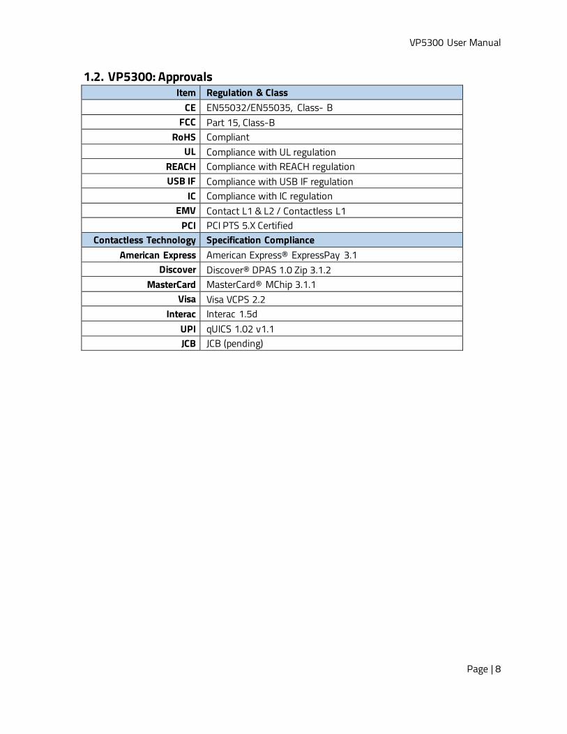
1.2. VP5300: Approvals Item Regulation & Class
CE EN55032/EN55035, Class- B FCC Part 15, Class-B
RoHS Compliant UL Compliance with UL regulation
REACH Compliance with REACH regulation USB IF Compliance with USB IF regulation
IC Compliance with IC regulation EMV Contact L1 & L2 / Contactless L1
PCI PCI PTS 5.X Certified Contactless Technology Specification Compliance
American Express American Express® ExpressPay 3.1 Discover Discover® DPAS 1.0 Zip 3.1.2
MasterCard MasterCard® MChip 3.1.1 Visa Visa VCPS 2.2
Interac Interac 1.5d UPI qUICS 1.02 v1.1 JCB JCB (pending)

VP5300 User Manual
Page | 9
2. VP5300 Specifications Physical
VP5300 Dimensions 136.2 mm from back of mounting surface x 102.8 mm flange width x 72.6 mm flange height (LxWxH)
NFC Antenna Bezel Dimensions 65mm x 54mm x 14.5mm (LxWxH), plus 15.5mm-deep M4 studs protruding from the back of the unit
Structure Material Plastic, PC UL 94V-0 Housing Color Black
Weight 0.7 kg Bezel Metallic, stainless steel look
Water drain feature allows liquids to drain Cable management Cables and connectors should be recessed from the case’s
rear surface and facing backwards Electrical
Voltage Requirement 12V DC (minimum) recommended to 24V maximum Environmental
Operating Temperature -25° C to 65° C (-13° F to 158° F), max change of 10° C per hour
Storage Temperature -40° C to 80° C (-40° F to 185° F) Operating Humidity 10% to 95% non-condensing
Storage Humidity 10% to 95% non-condensing, duration 3 months Transit Humidity 5% to 95% non-condensing, duration 1 week
Operating Environment Water resistant for indoor and outdoor use IK Rating IK 10 IP Rating IP 65
ESD1 (Device) Contact ±6kV Air discharge ±12kV
ESD (Mag head only) Contact ±6kV Air discharge ±12kV
Durability and Reliability Magnetic Head 1,000,000 swipes minimum
Rail 1,000,000 swipes minimum Smartcard connector 1,000,000 cycles minimum
Impact Resistance Pass IK 10 testing Ingress Resistance Pass IP 65 rating
NFC Antenna Hardware Specifications MTBF 466,000 hours
Receiver Subcarrier Data ISO 14443-2 Type A: Modified Manchester ISO 14443-2 Type
1 Note: Cables and connectors must be fully isolated with insulating material to prevent ESD discharge.

VP5300 User Manual
Page | 10
B: NRZ-L, BPSK ISO 18092 ISO 21481 (PCD & NFC)
Typical Read Range 4-6 cm (1.5 to 2.3 inches) NFC Antenna Electrical Specifications
Reader Input Voltage Supplied by the VP5300 <500mA (@9VDCIN) Working Current Rated power <3.8W
Maximum field strength 2.6 dBuA/m at 3 m

VP5300 User Manual
Page | 11
3. VP5300 Electrical Requirements Voltage requirement: 9VDC (minimum) is recommended, to 12V maximum.
3.1. Power Consumption • Stop Mode (without NFC) ≦85uA • Stop Mode (with NFC) ≦ 85uA
3.2. Current Draw VP5300 OPERATING MODE: 12VDC 9VDC
Normal 83mA 115mA Normal+MSR 86mA 120mA
Normal+ContactLess 190mA 264mA Normal+Contact EMV 85mA 125mA
Normal+Lan Connection 120mA 165mA Normal+L100 150mA 200mA
Normal+Contactless+L100 245mA 357mA Normal+Contactless+L100+ Lan
connection 285mA 410mA
Normal+Contactless+L100+Lan connection +BuzzerX2
325mA 470mA
Normal+L80 123mA 156mA Normal+Contactless+L80 231mA 305mA
Normal+Contactless+L80+ Lan connection
254mA 334mA
Normal+Contactless+L80+Lan connection +BuzzerX2
275mA 352mA
Sleep Mode, NFC off Sleep Mode, NFC on
47 μA 490 μA
88 μA 500 μA
Stop Mode, NFC off 42 μA 83 μA Stop Mode, NFC on 560 μA 490 μA
Battery: The unit contains a small lithium battery to power the Real Time Clock and certain anti- tamper features. This battery has a shelf life of five years. The battery is not user-replaceable. Do not attempt to open the VP5300 for any reason; this will trigger the anti-tamper features, causing the unit to become inoperable. If battery replacement is required, return the VP5300 to ID TECH. Contact [email protected] for more information.

VP5300 User Manual
Page | 12
3.3. Low-Power Modes The VP5300 has two low-power modes: Sleep Mode and Stop Mode. Power management is at the discretion of the application developer and set with firmware command F0-03 (which is described in the NEO Interface Developers Guide, available on request). Note that using the F0-03 command to control the unit's power state is limited to RS-232 operation and is not available in USB mode. Also note that when the VP5300 has been put in Stop Mode with the F0- 03 command, waking up the unit causes a warm reboot, which can take 5 seconds or more. Waking the unit up from Sleep Mode does not cause a reboot. The VP5300 can be awakened in RS-232 mode from Sleep Mode or Stop Mode by sending the device any command. In USB mode, establishing the USB connection wakes up the device.

VP5300 User Manual
Page | 13
4. VP5300 3-View Drawing

VP5300 User Manual
Page | 14
5. NFC Antenna 3-View Antenna mounting details:

VP5300 User Manual
Page | 15
6. VP5300 Installation This section provides information on how to install the VP5300 in an enclosure. Note that the unit may be installed edgewise (vertically), or in a horizontal manner. It can also be bolted to a surface, or custom-mounted flush with a surface. In the latter case, be sure to allow a 3mm (minimum) cutout clearance around the edge of the metal face flange (assuming the enclosure is metallic), to maintain good NFC performance. Do not tightly flush-mount the unit to a metal enclosure. Test NFC performance thoroughly to be sure no interference or signal attenuation occurs.
6.1. Parts List Make sure you have the following items before you start evaluation and testing:
• VP5300 Demo unit • L100 or L80 Demo unit • NFC Antenna • USB Cable • RS232 Cable • VP5300-L100 or -L80 cable • Power plug with EUR, AUS, UK • Mounting Brackets (801592239-001) x3 - 1 for the VP5300, 2 for the L100 or L80
6.2. Installing the Reader Refer to the VP5300 3-view drawing. Verify that power cords can physically reach the unit. Then proceed to:
• Locate, mark, and drill holes for the four main mounting points of the unit, spaced 89 mm apart lengthwise (on center), and spaced 45 mm apart (on center) along the short axis. Use a #12 drill.
• Secure the unit to the enclosure with bolts or screws of appropriate depth. Note that the anti-tamper nubs, located behind the mounting gasket on the unit's right side (when viewed head-on; the side nearest the molded-in ViVOpay logo), must be depressed when the unit is mounted. Ensure that the gasket is compressed to a degree necessary to ensure anti-tamper nub depression (and to protect against unnecessary moisture ingress).
VP5300 User Manual
Page | 16
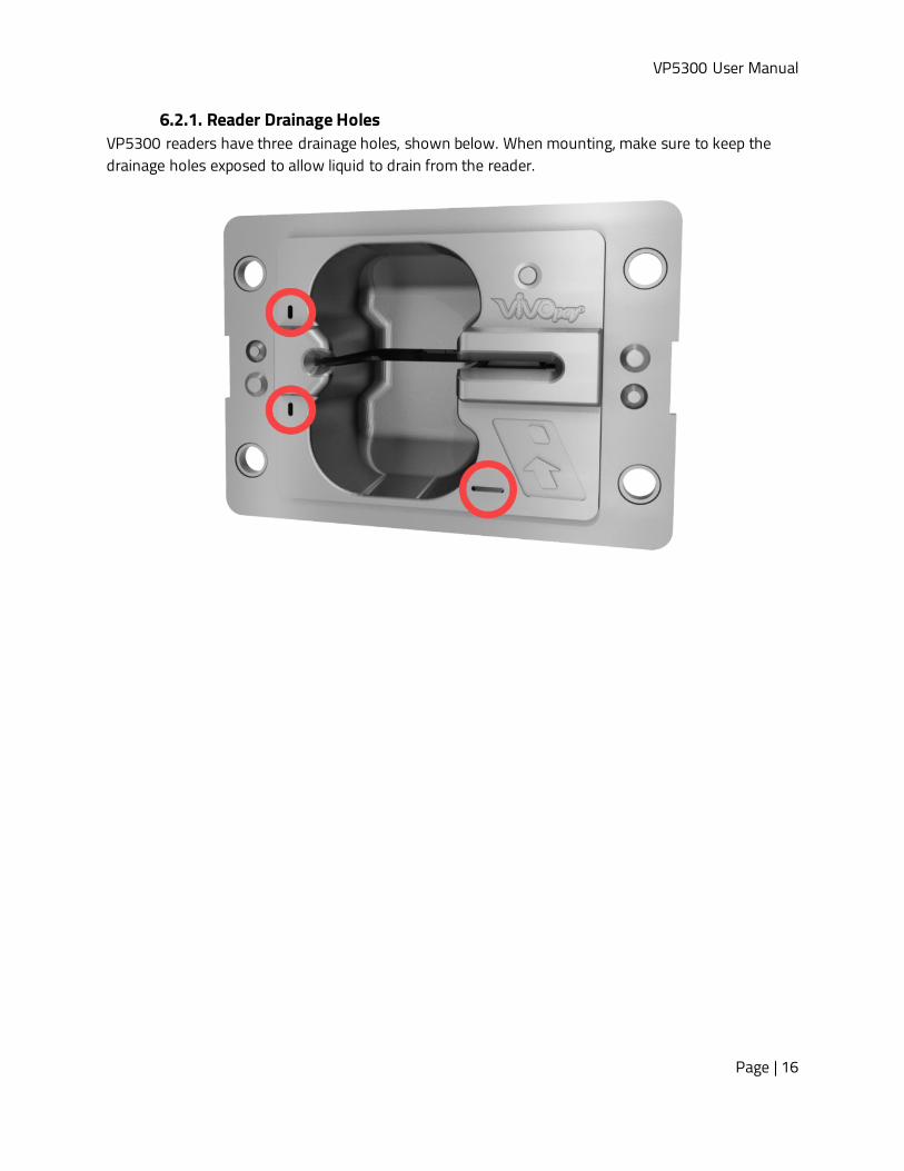
6.2.1. Reader Drainage Holes VP5300 readers have three drainage holes, shown below. When mounting, make sure to keep the drainage holes exposed to allow liquid to drain from the reader.

VP5300 User Manual
Page | 17
6.3. Mounting the VP5300 External NFC Antenna Refer to the VP5300 Antenna 3-view drawing. If you are using the VP5300’s contactless capability, you will need to install the optional NFC antenna and its cabling. Use the following instructions to mount the antenna on the exterior of a kiosk. Note: Product installers should experiment with and verify the orientation of the NFC Antenna before marking and drilling mounting holes, ensuring that the antenna is far enough away from the main body of the VP5300 so that insertion of a "tap card" in the unit's contact-EMV slot does not trigger an unwanted NFC interaction. Important: Mark holes in such a way as to ensure that the NFC Antenna is oriented with the LEDs at the top.
1. Locate and mark the four 4.5 mm (3/16 inch) mounting holes.
2. Locate and mark two 14.0 mm (0.551 inches) access holes (used for connecting the antenna barrel connector and the LED power and data cable to the unit. Notice that these holes are located off-center toward the top of the unit.
3. Drill the four 4.5 mm (3/16 inch) mounting holes.

VP5300 User Manual
Page | 18
4. Drill the two access holes (14.0 mm, 0.551 inch) holes using a 35/64 drill bit.
5. Use the nuts that are supplied with the unit (in plastic bag). 6. Route the end of the cable (80152235-001) with the RJ-45 connector through the
matching 14.0 mm (0.551 inch) hole into the kiosk. Make sure that the front of the antenna will be properly oriented (not upside down) on the kiosk before inserting the four screws into the mounting holes.
7. Align the four threaded posts with their mounting holes and attach the NFC Antenna to the mounting surface. Make sure that the cable is not pinched, rubbing, or binding.

VP5300 User Manual
Page | 19
8. Use the four nuts to secure the NFC Antenna to the surface of the kiosk. Make sure to tighten the nuts securely so that the antenna does not move freely on the outside surface of the kiosk.
Note: Tighten the nuts to 5-7 in/lbs. for a good weather-tight seal.
9. Attach the end of the cable with the SMB barrel connector through the right 14.0 mm (0.551 inch) hole and secure it to its socket on the back of the antenna. The SMB connector pushes onto the socket.
10. Attach the RJ-45 connector (male) coming from the NFC Antenna to the RJ-45 receptacle (female) on the 80152236-001 cable
.

VP5300 User Manual
Page | 20
6.3.1. Recommended Mounting Locations
Note: The 10mm gap described in the above diagram can be either an air gap or flush plastic material; the restriction is that metal needs to be more than 10mm away from the antenna.
6.3.2. Flush-Mounting the Antenna The antenna’s RF field is sensitive to the proximity of metal. There are three options when flush-mounting the antenna in a metal surface or bezel:
1. Mount with the RF emitting surface of the antenna at least 1cm forward of any metal. 2. Mount with the RF emitting surface of the antenna at least 1cm behind any metal.
Note: this reduces the antenna’s effective range. 3. Mount flush with the metal but allow a minimum of 1cm spacing between the antenna and
the metal. In all three cases, make sure to test the antenna mounting before engaging in a production-ready installation.

VP5300 User Manual
Page | 21
6.4. Attaching the Cables from the Antenna to the VP5300 1. Attach the SMB barrel end of the cable (80152236-001) from the antenna to the SMB
post of the VP5300. The connector slides on. 2. Attach the 8-pin end of the cable (80152236-001) from the antenna to the VP5300,
where the receptacle sits next to the RJ-45 (Ethernet) receptacle.
6.5. Connecting to Power The VP5300 can be powered through the RS-232 communications cable or the USB Y-connector. In either case, the VP5300 requires the +9VDC power supply to operate.
1. Connect the +9VDC power supply (P/N 140-2035-00) to the barrel receptacle on the RS-232 cable or the barrel part of the Y-cable for USB by sliding the power supply barrel into the receiving recess.
2. Plug the unit in to an AC outlet and verify that the VP5300 lights up. Note: The VP5300 requires a power supply whether connected by RS-232 or USB.

VP5300 User Manual
Page | 22
6.6. Connecting to the Host Port Use 9-pin Joint Tech P/N A2002H-09P (or equivalent) for the mating connector. See diagrams below for RS-232 or USB, as appropriate.
6.7. VP5300 External Cable Pin Assignments: RS-232
6.8. VP5300 External Cable Pin Assignments: USB
VP5300 User Manual
Page | 23
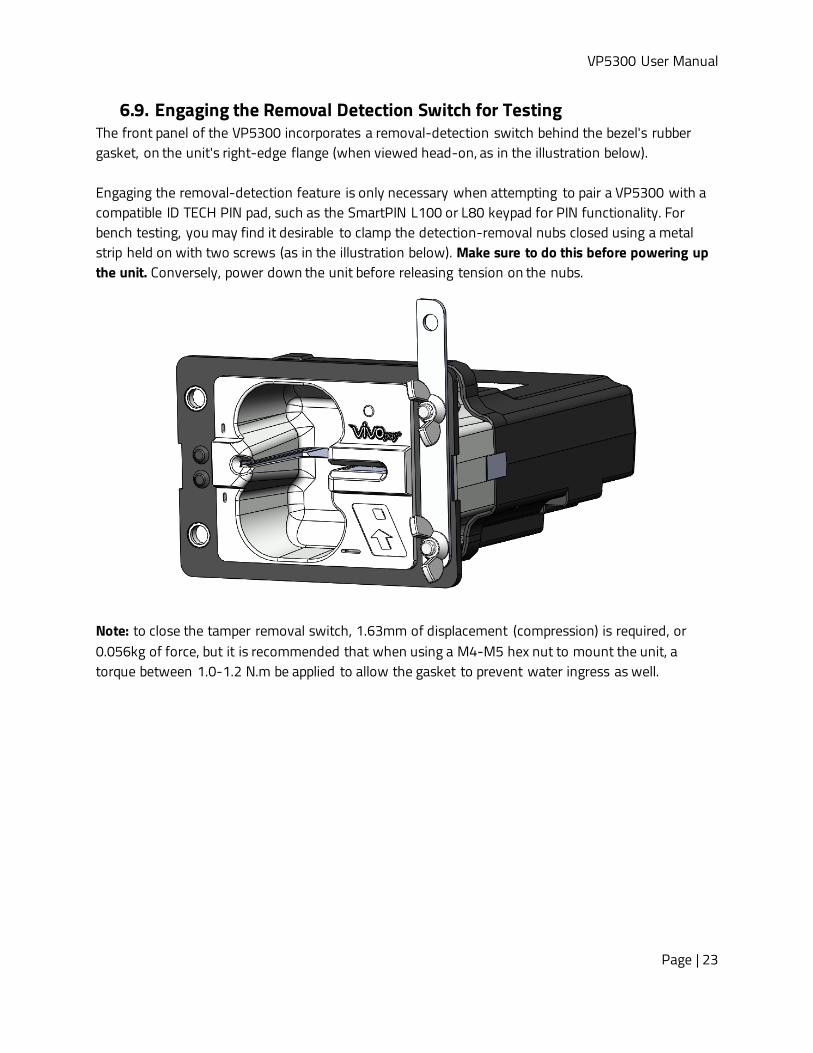
6.9. Engaging the Removal Detection Switch for Testing The front panel of the VP5300 incorporates a removal-detection switch behind the bezel's rubber gasket, on the unit's right-edge flange (when viewed head-on, as in the illustration below). Engaging the removal-detection feature is only necessary when attempting to pair a VP5300 with a compatible ID TECH PIN pad, such as the SmartPIN L100 or L80 keypad for PIN functionality. For bench testing, you may find it desirable to clamp the detection-removal nubs closed using a metal strip held on with two screws (as in the illustration below). Make sure to do this before powering up the unit. Conversely, power down the unit before releasing tension on the nubs.
Note: to close the tamper removal switch, 1.63mm of displacement (compression) is required, or 0.056kg of force, but it is recommended that when using a M4-M5 hex nut to mount the unit, a torque between 1.0-1.2 N.m be applied to allow the gasket to prevent water ingress as well.

VP5300 User Manual
Page | 24
6.10. Installation Notes • The VP5300 is designed to be mounted on a metal surface and in reasonably close proximity
to any internal motors and electrical devices that may be operating inside the kiosk. However, the unit (like all NFC/RFID devices) is susceptible to RF and electromagnetic interference. It is important that the unit not be mounted near (within 3 or 4 feet of) large electric motors, computer UPS systems, microwave transmitters, anti-theft devices, radio transmitters, routers, and so on.
• Close proximity of metal to antenna’s the RF-emitting end can greatly reduce the antenna’s range.
• Tie all cables neatly with nylon cable-ties and route them so that they are inaccessible and invisible to customers. Label the cable ends as "host," "ViVOpay," and "power" to simplify connection testing or component replacement, particularly when untrained individuals might be involved.
• Test the installation using a test card to perform an end-to-end transaction (the same as an actual purchase). The NFC antenna front panel's light should illuminate. Even if the transaction is declined (as it should be with a test card), it will prove connectivity all the way through the system. If possible, the store manager or some other responsible party should test each VP5300 on a regular basis (perhaps at the start of each day or at least once per week) with a test card to ensure continued operation and functionality. If the unit is manually rebooted, it is important to test the contactless reader portion as soon as possible afterwards to verify continued communication.
6.11. 24-Hour Device Reboot Per PCI Requirements, this device reboots every 24 hours and performs a firmware self-check at that time. Please contact your device integrator if you need to check the reboot time for your unit.

VP5300 User Manual
Page | 25
7. LED Management There are two LEDs. One is the user-interface LED on the front bezel of the reader; the other (diagnostic) LED is on the back.
Front LED Status
• The LED turns green in idle waiting. • LED handling for Magstripe card operation:
o The LED will turn red to indicate that the recent magstripe card read was bad. • LED handling for smart card operation:
o The Green LED will flash after powering on the smart card. o The solid Green LED indicates smart card processing is complete and the ICC powered
off. The user can remove the smart card.
State LED Indicating
0 Off No external power 1 Flashing
Green Powering on the smart card and starting smart card operation
2
Solid Green
Idle waiting (Smart card processing is complete and the ICC powered off. User can remove the smart card. If the transaction mode was MSR, magstripe card data is sent out.)
3 Solid Red The recent magstripe card read was bad. Red lasts 1 second.

VP5300 User Manual
Page | 26
7.1. Diagnostic LED Status The LED on the back of the VP5300 is intended to be used for diagnostic purposes.
LED status:
1. Off 2. Solid – No communication with its host. 3. Flashing (1 sec on, 1 sec off) – Communicating with its host.
LED Colors:
• Amber – Reader requires on-site service actions. • Green – Reader is ready to read cards. • Red – Reader needs to be sent back to the manufacturer.
State Green LED Amber LED Red LED Indicating Service action
1
Off
Off
Off No external power. Check the power cable and power supply.
2 Solid Red Power is on, but firmware doesn't run.
Dismount the device and send it back to the manufacture.
3 Solid Amber
Off
Solid amber normally means the front removal-detection buttons (left side of front bezel) are not depressed. If this possibility is ruled out, check host connectivity.
Check that the removal detection button is fully depressed. Check the communication cable and if host is running.
4 Solid Green Solid
Amber
Power on. First restart and no command sent. In not ready state and waiting for host to communicate.
No action required.

VP5300 User Manual
Page | 27
State Green LED Amber LED Red LED Indicating Service action 5 N/A N/A N/A N/A
6 Flashing Green Flashing Amber
Firmware downloading and programming in progress. Wait for download to finish.
7 Solid Green Off
In ready state but no communication with its host. Check connections.
8 Flashing Green Command sent to reader; reader waiting for response.
Check L100 OR L80 display for message.
9
Flashing Amber Removal flag is on and
communicating with its host.
Check removal switch (under the gasket on the unit's front flange, on the right) to see if it is fully engaged; if necessary, call service center to reactivate the reader.
10 Solid
Amber
Solid Red
Reader has no communication with its host, and the crypto driver is not functioning: Crypto MCU is lost or certificates are invalid (unit may be tampered).
Dismount the reader and send it back to the manufacturer.
11 Flashing Amber
Reader is communicating with its host, and the crypto driver is not functioning: Crypto MCU is lost or certificates are invalid (unit may be tampered).
Dismount the reader and send it back to the manufacturer.
VP5300 User Manual
Page | 28
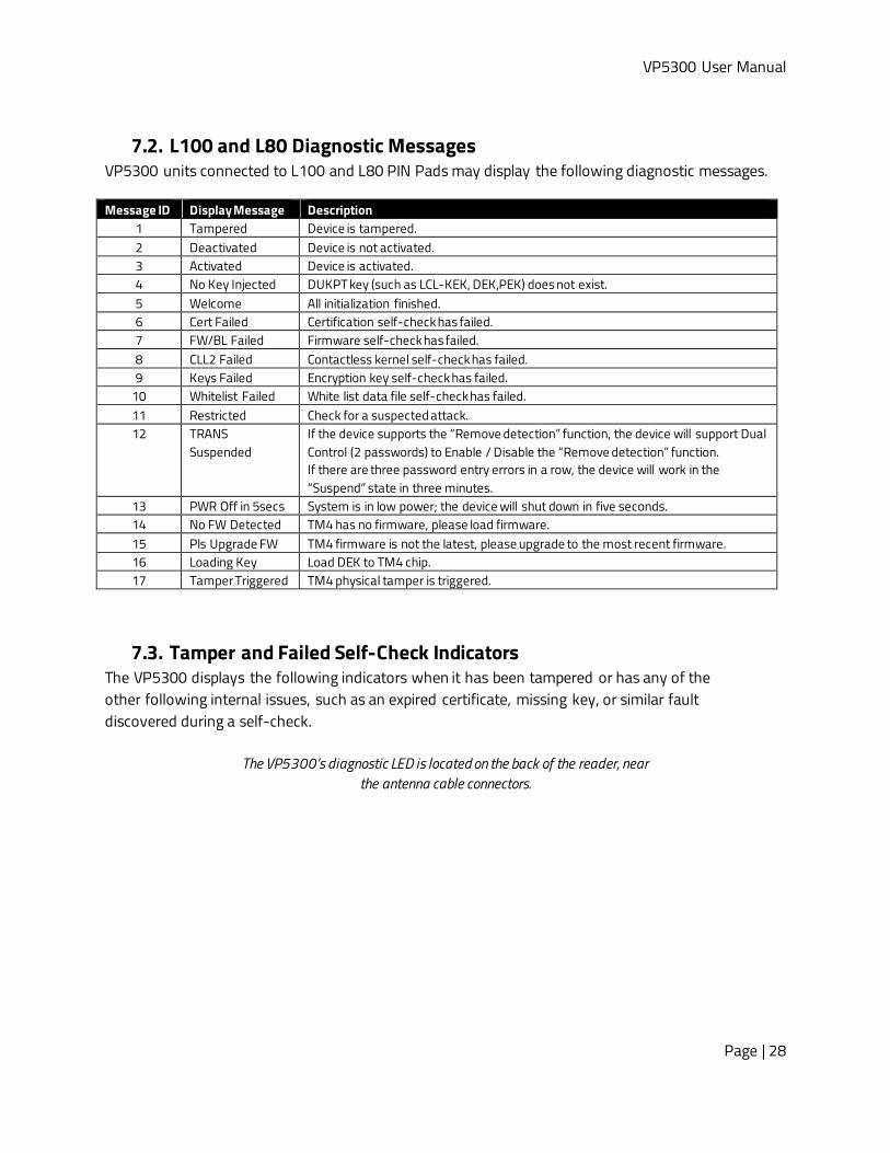
7.2. L100 and L80 Diagnostic Messages VP5300 units connected to L100 and L80 PIN Pads may display the following diagnostic messages. Message ID Display Message Description Message ID Display Message Description
1 Tampered Device is tampered. 2 Deactivated Device is not activated. 3 Activated Device is activated. 4 No Key Injected DUKPT key (such as LCL-KEK, DEK,PEK) does not exist. 5 Welcome All initialization finished. 6 Cert Failed Certification self-check has failed. 7 FW/BL Failed Firmware self-check has failed. 8 CLL2 Failed Contactless kernel self-check has failed. 9 Keys Failed Encryption key self-check has failed.
10 Whitelist Failed White list data file self-check has failed. 11 Restricted Check for a suspected attack. 12 TRANS
Suspended If the device supports the “Remove detection” function, the device will support Dual Control (2 passwords) to Enable / Disable the “Remove detection” function. If there are three password entry errors in a row, the device will work in the “Suspend” state in three minutes.
13 PWR Off in 5secs System is in low power; the device will shut down in five seconds. 14 No FW Detected TM4 has no firmware, please load firmware. 15 Pls Upgrade FW TM4 firmware is not the latest, please upgrade to the most recent firmware. 16 Loading Key Load DEK to TM4 chip. 17 Tamper Triggered TM4 physical tamper is triggered.
7.3. Tamper and Failed Self-Check Indicators The VP5300 displays the following indicators when it has been tampered or has any of the other following internal issues, such as an expired certificate, missing key, or similar fault discovered during a self-check.
The VP5300’s diagnostic LED is located on the back of the reader, near the antenna cable connectors.

VP5300 User Manual
Page | 29
Indicator Tampered Status Other Issue Status Front LED Off All LEDs off
Back Diagnostic LED Solid red See below SmartPIN L100 or L80 LCD TAMPERED See below
Buzzer Alarm tone Alarm tone When paired to a SmartPIN L100 or L80, the VP5300 can indicate the following issues in the event of a failed self-check:
• "CERT FAILED" indicates the battery is drained or certificate expired. • "FW/BL FAILED" indicates the bin and sign do not match. • "CLL2" indicates the Contactless kernel self-check failed. • "KEYS FAILED" if no injection key happened. • "WHITELIST FAILED" indicates that CL or MSR whitelist verification failed.
VP5300 User Manual
Page | 30
8. Using the VP5300 to Make a Contactless Purchase
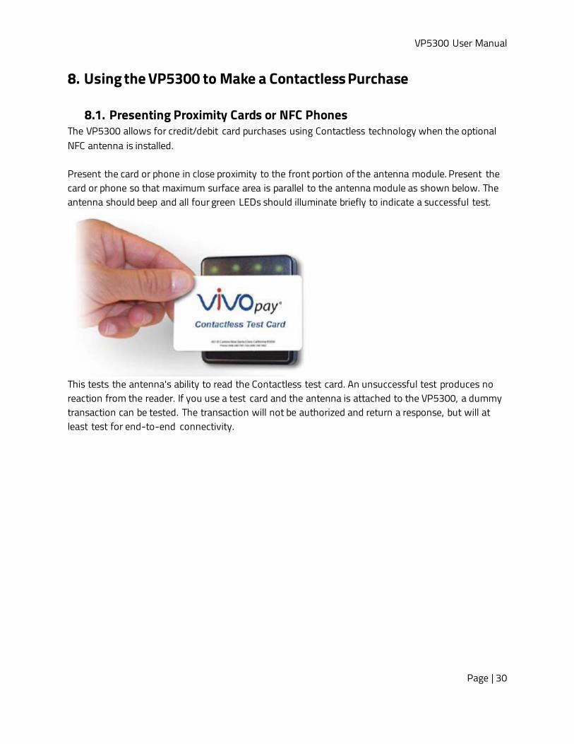
8.1. Presenting Proximity Cards or NFC Phones The VP5300 allows for credit/debit card purchases using Contactless technology when the optional NFC antenna is installed. Present the card or phone in close proximity to the front portion of the antenna module. Present the card or phone so that maximum surface area is parallel to the antenna module as shown below. The antenna should beep and all four green LEDs should illuminate briefly to indicate a successful test.
This tests the antenna's ability to read the Contactless test card. An unsuccessful test produces no reaction from the reader. If you use a test card and the antenna is attached to the VP5300, a dummy transaction can be tested. The transaction will not be authorized and return a response, but will at least test for end-to-end connectivity.

VP5300 User Manual
Page | 31
9. Pairing with PIN Pad The VP5300 is designed to be paired with ID TECH's SmartPIN L100 or L80 keypads to create a full chip- and-PIN solution. Follow the pairing procedures below to use the L100 or L80 with the VP5300. First, set up the L100 or L80 for paired operation by specifying two user passwords; then set up the VP5300; and then, finally, pair the two devices.
9.1. Setting up the L100 or L80 1. Cycle the power to the insert reader (unplug the power from the USB cable and plug it back
in). 2. After plugging the power into the USB cable again, you have only 2 seconds to begin entering
the special pairing command on the keypad (otherwise, you'll need to cycle the power again). To get into the special menu, press the following keys in this order:
SmartPIN L100 SmartPIN L80 • Cancel • Clear • Enter • Blank • Clear • Enter
• Cancel • 5 • Enter • 0 • 5 • Enter
3. The L100 or L80 will start beeping to indicate that the user passwords are not yet set and the LCD screen will prompt to enter a password.
4. Enter default Password A: 12345678. Make sure the device beeps after each button is pressed to register the input. After correctly entering the default Password A, the device beeps twice.
5. Enter a new user-created Password 1 to replace Password A. The new Password 1 must be eight digits (for example: 11111111). After entering the new Password 1, the device beeps twice to confirm the input. Make a note of the new Password 1 in your records.
6. The device will prompt to reenter the password. Enter the new Password 1 again to confirm it. After entering the new Password 1 a second time, the device beeps twice to confirm successful verification.
7. Next, enter default Password B: 87654321. Make sure the device beeps after each button is pressed to register the input. After entering the default Password B correctly, the device beeps twice.
8. Enter a new user-generated Password 2 to replace Password B. The new Password 2 must be 8 digits and must be different from Password 1 (for example: 22222222). After entering the new Password 2, the device beeps twice to confirm successful verification. Make a note

VP5300 User Manual
Page | 32
of the new Password 2 in your records. 9. The device prompts to reenter the password. Enter the new Password 2 again to confirm it.
After entering the new Password 2 for a second time, the device beeps twice to confirm the input. The SmartPIN L100 or L80 Removal Detection passwords are now set.
10. The next menu on the L100 or L80 screen has the option to Enable. Choose the top option (scroll up or down using the * and # keys) and press the green Enter key. The device displays an "Activate Success" prompt to indicate success.
9.2. Setting up the VP5300 To set up the VP5300 for chip-and-PIN operation, you will need to configure the unit to operate in Configuration 3C. Out of the box, the VP5300 uses the 4C configuration, which indicates the reader performs EMV transactions without a PIN pad. Switching the unit to a 3C configuration can be done easily with ID TECH's free USDK Demo program on any Windows computer. Download the free demo program from the ID TECH .NET Universal SDK page (look for dot NET SDK Demo.zip). No registration is required. 1. Launch the USDK Demo program and plug the VP5300 into the USB port of your computer. Verify
that the VP5300 is shown as selected on the left side of the window:
2. Verify that the firmware version of your VP5300 is higher than v72. If the firmware version is
lower, please contact your ID TECH sales rep for more instructions.

VP5300 User Manual
Page | 33
3. Open Commands > EMV > Terminal Config to expose command names. Select the Set Config #3 command and click the Execute Command button. This configures the VP5300 reader to accept 3C configuration settings.
4. Find the Save Terminal Data command (see below). When you select it, the upper portion of the center panel will change appearance and show a CONFIG dropdown menu along with a TLV text area. Select 3C from the dropdown (leave the TLV area as it is), then click Execute Command.

VP5300 User Manual
Page | 34
9.3. Pair the Devices 1. Open Device > Send NEO Command. Enter 63 for Cmd and 01 for Sub in the text boxes at the top
of the center panel (as shown below). This command pairs the readers.

VP5300 User Manual
Page | 35
2. The VP5300 is now fully configured to do PIN-based transactions (if the presented credit card supports them). Verify that the VP5300’s front removal detection switch is firmly pressed down. The pressure switch is located on the front bezel, right side, behind the rubber gasket. If the unit is not mounted in a kiosk or other fixture, you can temporarily engage the pressure switch by attaching a strip of metal to the right side of the flange as shown below (note the wing nuts):
3. Next, return to the L100 or L80 and power-cycle the PIN pad. You have only 2 seconds to start entering the special pairing command on the keypad. To get into the special menu, press:
SmartPIN L100 SmartPIN L80 • Cancel • Clear • Enter • Blank • Clear • Enter
• Cancel • 5 • Enter • 0 • 5 • Enter

VP5300 User Manual
Page | 36
9.3.1. Enabling SmartPIN L100 Devices 1. The L100 or L80 front display now shows two options: Enable PinPad, and Enable CR (in this
case, CR means "card reader"). Use the # and * keys to scroll up or down. Select Enable CR and press Enter.
2. Setup is now complete. Execute the Start EMV Transaction command in the USDK Demo, or start
a transaction from your own software, and then insert a PIN debit card. After the prompt for PIN comes up, the unit should display “ENTER PIN:” as shown below:
Note: The test card must be a PIN-capable EMV card. We recommend using the appropriate test card from a deck of test cards.
VP5300 User Manual
Page | 37
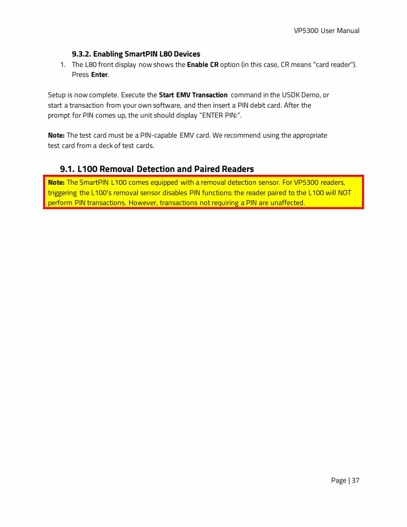
9.3.2. Enabling SmartPIN L80 Devices 1. The L80 front display now shows the Enable CR option (in this case, CR means "card reader").
Press Enter. Setup is now complete. Execute the Start EMV Transaction command in the USDK Demo, or start a transaction from your own software, and then insert a PIN debit card. After the prompt for PIN comes up, the unit should display “ENTER PIN:”. Note: The test card must be a PIN-capable EMV card. We recommend using the appropriate test card from a deck of test cards.
9.1. L100 Removal Detection and Paired Readers Note: The SmartPIN L100 comes equipped with a removal detection sensor. For VP5300 readers, triggering the L100's removal sensor disables PIN functions: the reader paired to the L100 will NOT perform PIN transactions. However, transactions not requiring a PIN are unaffected.

VP5300 User Manual
Page | 38
10. Implementing Whitelists For instructions on implementing Whitelists for the VP5300, contact your ID TECH representative to receive the user guide ID TECH Implementing Whitelists, available under NDA.
11. RF Interference Q. Why do I need to know about RF interference? A. Contactless payment devices use radio frequency technology to send card data to a contactless terminal reader. Q. How can RF interference affect contactless payment? A. Radio frequency interference can cause data errors. If RF interference is present, contactless payment devices may operate intermittently or inconsistently. Q. Where does RF interference come from? A. Radio frequency interference (RFI) can originate from a wide number of sources at the point-of-sale (POS). Some examples of sources of RF energy and RF interference include:
• AM/FM radio and TV transmitters • 2-way radios and pagers • Mobile telephones • Power lines and transformers • Large electric motors • Medical equipment • Microwaves • Electromechanical switches • Wireless routers
Q. What should I do if I suspect RF interference exists in my environment? A. Begin by inspecting your environment for possible sources of RF interference. Q. Do equipment manufacturers test their devices for RF interference? A. Yes. Electronic equipment is tested for RFI sensitivity by the manufacturers. These tests are performed in a controlled laboratory environment and will often not replicate the types of situations that would be encountered in your own point-of-sale (POS) environment. Q. What RF levels will impact RF operations? A. Factors that can cause RF interference vary case-by-case. There are no set rules defining a single RF level that will cause RFI. RFI depends on the sensitivity of the equipment under consideration, or how low an interpreting signal can be in the presence of the equipment and cause problems. Equipment can be particularly sensitive to very low signal levels of one frequency and yet be quite

VP5300 User Manual
Page | 39
immune to high signal levels of another frequency; frequency is an important factor. Some electronic system components are internally shielded and have a very high immunity to interference; but generally, most equipment has not been so engineered.

VP5300 User Manual
Page | 40
12. Updating VP5300 Firmware Users can update VP5300 firmware with a Windows computer via either serial or USB interfaces. Note: Before you begin, go to the VP5300 product page on the ID TECH Knowledge Base, download the Firmware update package; VP5300; production ZIP file, and extract it to your computer. You will also need to install ID TECH’s Universal SDK Demo app, available free on the ID TECH Knowledge Base. Follow the steps below to update VP5300 firmware:
1. Connect the VP5300 to your PC via USB or serial port. 2. Open the USDK Demo app from the Windows Start menu.
3. Under Firmware, select Update Device Firmware, then click Execute Command.

VP5300 User Manual
Page | 41
4. In the Firmware Type dialog, enter 255 for K81 FW and click OK.
5. In the File Explorer window, navigate to the directory where you saved the VP5300 firmware
update, open the FirmwareApp directory, and select the FW file that starts with VP5300 v1.00... and click Open.
6. The VP5300 reboots and enters the bootloader, at which point the USDK Demo app begins
updating the device’s firmware. 7. When the firmware update completes, the VP5300 reboots again and the USDK Demo app
prints Firmware Update Successful in the Results panel.

VP5300 User Manual
Page | 42
13. Decommissioning PCI-Certified Devices All PCI devices require proper decommissioning prior to device disposal in order to ensure the protection of all sensitive financial card data. For instructions on decommissioning your device, see Decommissioning of PCI-Certified Devices on the ID TECH Knowledge Base.
14. Troubleshooting The VP5300 reader is designed to be reliable and easy to troubleshoot. The components that may require troubleshooting include the power module (if applicable), the reader, and the serial cable. If you are unable to resolve the problem, please contact mailto:[email protected] (sending an e-mail to this address will automatically open a support ticket).
14.1. A Note About Encryption When a key is not injected into the VP5300, it has limited functionality and will be in a state looking for key injection. Without a key, all requests to start a transaction result in an error code that the command is not allowed. After a key is injected into the VP5300, there is no method to turn off encryption.
Symptom Possible Cause Remedy General Issues Reader does not appear to be powered on (no LEDs are lit).
• Reader not powered on or incorrect voltage.
• Improper use of internal power supply provided by the kiosk.
• Check cable connections. • Verify that power is on and correct voltage and
current are present. • Make sure that the correct pins are utilized. • Make sure that the power provided is within the
specified range of the reader. • Make sure that the correct polarity is observed. • For more information, refer to the Input Voltage
under the Electrical specification section. • Replace the device with a known-good device to
verify that the power supply and wiring in the installation are sound.
Reading Cards/Phones LED is lit, but beeper is not audible when card/fob presented.
• Card/fob/phone not properly presented.
• RF interference. • Unsupported card used. • Wrong firmware (contact your
local support representative).
• Present card/fob/phone closer to the antenna, and ensure it is parallel to the face of the reader.
• Verify that the card/fob/phone is valid/current. • Verify that metal is not interfering with the
antenna. • Test with “ViVOcard Contactless Test Card” part
number 241-0015-03 Rev A.

VP5300 User Manual
Page | 43
Symptom Possible Cause Remedy • Try a different card/fob. • Check to see if card/fob is damaged. • Verify that correct firmware is loaded on reader
(local support representative only). • Power cable plug is fully inserted. • Replace the unit.
Some cards/fobs read, but not all.
• Possible bad card/fob. • Unsupported card used. • Wrong firmware (contact your
local support representative).
• Check to see if card/fob is damaged. • Verify that correct firmware is loaded on reader
(local support representative only). • Card readers must contain the latest versions of
card-brand public certificates (CAPKs). If a CAPK is out of date, one particular kind of card may no longer be usable. Update the CAPK.
Communication to Kiosk No data is received, or data is garbled.
Faulty or incorrect cable connections.
• Check that the cable connection is secure and in the correct port on the unit.
Load Firmware Firmware loading software indicates “open RS-232 failed”
Device is not well connected to PC. Or other software is using the serial interface.
• Check the cable connection • Close other software which might be using the same
serial interface. Firmware loading software indicates “Load firmware failed."
Device is not well connected to PCs.
• Check the cable connections.
Firmware loading software indicates “Send Command failed.”
Bootloader firmware in device is destroyed.
• Contact your support representative to reload manufacture's firmware.
VP5300 User Manual
Page | 44
16. FCC Regulatory Compliance Notices Class B Equipment This device complies with Part 15 of the FCC Rules. Operation is subject to the following two conditions: (1) this device may not cause harmful interference, and (2) this device must accept any interference received, including interference that may cause undesired operation. The user manual for an intentional or unintentional radiator shall caution the user that changes or modifications not expressly approved by the party responsible for compliance could void the user’s authority to operate the equipment. Note: The grantee is not responsible for any changes or modifications not expressly approved by the party responsible for compliance. Such modifications could void the user’s authority to operate the equipment. Note: This equipment has been tested and found to comply with the limits for a Class B digital device, pursuant to part 15 of the FCC Rules. These limits are designed to provide reasonable protection against harmful interference in a residential installation. This equipment generates uses and can radiate radio frequency energy and, if not installed and used in accordance with the instructions, may cause harmful interference to radio communications. However, there is no guarantee that interference will not occur in a particular installation. If this equipment does cause harmful interference to radio or television reception, which can be determined by turning the equipment off and on, the user is encouraged to try to correct the interference by one or more of the following measures:
• Reorient or relocate the receiving antenna. • Increase the separation between the equipment and the receiver. • Connect the equipment into an outlet on a circuit different from that to which the receiver is connected. • Consult the dealer or an experienced radio/TV technician for help.
This device complies with FCC RF radiation exposure limits set forth for an uncontrolled environment. The antenna(s) used for this transmitter must not be co-located or operating in conjunction with any other antenna or transmitter and must be installed to provide a separation distance of at least 20cm from all persons.
17. IC Compliance Warning This device contains licence-exempt transmitter(s)/receiver(s) that comply with Innovation, Science and Economic Development Canada’s licence-exempt RSS(s). Operation is subject to the following two conditions:
1. This device may not cause interference, and 2. This device must accept any interference, including interference that may cause undesired operation of the device.
L’émetteur/récepteur exempt de licence contenu dans le présent appareil est conforme aux CNR d’Innovation, Sciences et Développement économique Canada applicables aux appareils radio exempts de licence. L’exploitation est autorisée aux deux conditions suivantes :
1. l'appareil ne doit pas produire de brouillage, et, and 2. l'utilisateur de l'appareil doit accepter tout brouillage radioelectrique subi, meme si le brouillage est susceptible
d'en compromettre le fonctionnement.

VP5300 User Manual
Page | 45
18. Cautions and Warnings
Warning: Avoid close proximity to radio transmitters which may reduce the capability of the reader. Avertissement : Évitez la proximité d'émetteurs radio, ce qui peut réduire la performance du lecteur.
Caution: Do not drop the device. Attention : Ne pas laisser tomber le lecteur
Caution: Electrostatic sensitive device. Use caution in handling, in high ESD conditions. Attention : Le lecteur est sensible aux décharges électrostatiques. Manipulez le lecteur avec précaution dans une situation d’électricité statique élevée.