vortex-induced vibrations (viv)
TRANSCRIPT

Vortex-induced vibrations (VIV)PEF 6000 - Special topics on dynamics of structures
Associate Professor Guilherme R. Franzini
1/59PEF 6000

Outline
1 Objectives
2 VIV-1dof
3 VIV-2dof
4 Flexible cylinder VIV
5 VIV modeling: wake-oscillator model
2/59PEF 6000

Outline
1 Objectives
2 VIV-1dof
3 VIV-2dof
4 Flexible cylinder VIV
5 VIV modeling: wake-oscillator model
3/59PEF 6000

Objectives
• To present the physical aspects of the VIV phenomenon. Focus on the �owaround a cylinder and the vortex-shedding phenomenon!
• Examples of references: Textbooks by Blevins (2001), Païdoussis et al (2011),Naudascher & Rockwell (2005), the reviews by Sarpkaya (2004) and Williamson& Govardhan (2004) e selected papers.
• The graduate course PNV5203 - Fluid-Structure Interaction 1 brings deeplierconcepts on the theme.
4/59PEF 6000

Oscillating cylinder
• A cylinder immersed in �uid can oscillate either by the action of prescribedmotions (forced oscillations) or due to the �uid-structure interaction. The lattescondition is focus of this class.
• The oscillations leads to modi�cation in the �ow �eld. Among the
modi�cations, we highlight
1 Increase in the vortex strength;
2 Increase in the correlation length;3 Increase in the mean drag coe�cient;4 Changes in the vortex-shedding pattern.
5/59PEF 6000

Oscillating cylinder
• A cylinder immersed in �uid can oscillate either by the action of prescribedmotions (forced oscillations) or due to the �uid-structure interaction. The lattescondition is focus of this class.
• The oscillations leads to modi�cation in the �ow �eld. Among the
modi�cations, we highlight
1 Increase in the vortex strength;2 Increase in the correlation length;
3 Increase in the mean drag coe�cient;4 Changes in the vortex-shedding pattern.
5/59PEF 6000

Oscillating cylinder
• A cylinder immersed in �uid can oscillate either by the action of prescribedmotions (forced oscillations) or due to the �uid-structure interaction. The lattescondition is focus of this class.
• The oscillations leads to modi�cation in the �ow �eld. Among the
modi�cations, we highlight
1 Increase in the vortex strength;2 Increase in the correlation length;3 Increase in the mean drag coe�cient;
4 Changes in the vortex-shedding pattern.
5/59PEF 6000

Oscillating cylinder
• A cylinder immersed in �uid can oscillate either by the action of prescribedmotions (forced oscillations) or due to the �uid-structure interaction. The lattescondition is focus of this class.
• The oscillations leads to modi�cation in the �ow �eld. Among the
modi�cations, we highlight
1 Increase in the vortex strength;2 Increase in the correlation length;3 Increase in the mean drag coe�cient;4 Changes in the vortex-shedding pattern.
5/59PEF 6000
Vortex-induced vibrations (VIV)
Self-excited and self-limited resonant phenomenon;
• VIV of rigid cylinders, mounted on elastic supports that allow oscillations only inthe cross-wise direction (VIV-1dof);
• VIV of rigid cylinders, mounted on elastic supports that allow oscillations in thecross-wise direction and in the in-line directions(VIV-2dof);
• VIV of �exible cylinders.
6/59PEF 6000

Outline
1 Objectives
2 VIV-1dof
3 VIV-2dof
4 Flexible cylinder VIV
5 VIV modeling: wake-oscillator model
7/59PEF 6000

Description
• Rigid cylinder of immersed length L, assembled onto an elastic support ofsti�ness k and damping constant c. The total oscillating mass is m andoscillations are allowed only in the cross-wise direction. The free-stream velocityis uniform and time-invariant of value U∞.
8/59PEF 6000

Description
• Rigid cylinder of immersed length L, assembled onto an elastic support ofsti�ness k and damping constant c. The total oscillating mass is m andoscillations are allowed only in the cross-wise direction. The free-stream velocityis uniform and time-invariant of value U∞.
8/59PEF 6000

Setup
Free-stream velocity align with the x direction
Cross-flow direction - y(y(t), C (t))L
LowerLeaf Springs
Flowdirection
Lowerplate
Load Cell
700
Clamp
Extracted from Franzini et al (2012).9/59
PEF 6000

Important quantities
Tabela: Important quantities. Adapted from Khalak & Williamson(1999).
Quantity Symbol De�nition
Mass ratio parameter m∗ msρπD2L/4
Structural damping ratio ζ cs
2
√k(ms+mapot )
Natural frequency in still water fN
√k
m+mapot
Reduced velocity VRU∞fND
Dimensionless amplitude A∗AyD
Dimensionless frequency f ∗ ffN
Drag coe�cient CDFD
1
2ρU2∞DL
Lift coe�cient CLFL
1
2ρU2∞DL
Reynolds number Re U∞Dν
10/59PEF 6000

Added mass
• Term of the hydrodynamic load in phase with the cylinder acceleration. It is alsoassociated with the �uid's kinetic energy;
• Within potential �ow theory, it is the force that the �uid imposed on anoscillating body F = −mau;
• Also in the context of the potential �ow theory, a circular cylinder immersed inan in�nity domain has its added mass coe�cient Ca = ma/md = 1, md beingthe mass of �uid displaced by the body;
• Considering viscous �uids, the added mass coe�cient may be signi�cantlydi�erent from 1.
11/59PEF 6000

Lock-in
• In the �ow around a �xes cylinder, the lift force can be assumed as harmonicand monochromatic as FL(t) = FL sinωs t, ωs = 2πfs = 2π StU∞
D, ωs being the
vortex-shedding frequency;
• If the rigid cylinder is assembled onto an elastic support, the natural frequency
of the system is fN = 12π
√k
m+mpota
.
• If fs ≈ fN → Resonance.
• Lock-in: 3 < VR < 12 ans is characterized by fs ≈ fN →. As the cylinderoscillates, the wake is modi�ed and, consequently, the Strouhal number changes.
• Under lock-in, the cylinder oscillates due to the �ow excitation, giving rise tothe vortex-induced vibration (VIV) phenomenon. The maximum oscillationamplitude is close to one diameter.
12/59PEF 6000

Response curves
Experiments carried out using water as the surrounding �uid have smaller values of m∗
than those developed in airFranzini et al (2012): Experiments in water, m∗ = 2.6;m∗ζ = 0.0018
0 2 4 6 8 10 120
0.2
0.4
0.6
0.8
1
VR = U/fND
A∗ y
Present work Khalak & Williamson (1999)
Extracted from Franzini et al. (2012).
13/59PEF 6000

Response curves
0 2 4 6 8 10 120
0.2
0.4
0.6
0.8
1
1.2
1.4
1.6
1.8
2
St = 0,20
VR = U/fND
f∗
=f d
y/f N
Extracted from Franzini et al. (2012).
• The dimensionless oscillation frequency does not remain constant and close to 1for systems with low value of m∗ζ.
14/59PEF 6000

Response curves
0 2 4 6 8 10 120
0.2
0.4
0.6
0.8
1
1.2
1.4
1.6
1.8
2
St = 0,20
VR = U/fND
f∗
=f d
y/f N
Extracted from Franzini et al. (2012).• The dimensionless oscillation frequency does not remain constant and close to 1
for systems with low value of m∗ζ.
14/59PEF 6000

Response curves
0 2 4 6 8 10 120
0.5
1
1.5
2
2.5
3
3.5
4
4.5
VR = U/fND
CD
Present work Khalak & Williamson (1997)
Extracted from Franzini et al. (2012).
• Marked ampli�cation of the mean drag coe�cient within the lock-in.
15/59PEF 6000

Response curves
0 2 4 6 8 10 120
0.5
1
1.5
2
2.5
3
3.5
4
4.5
VR = U/fND
CD
Present work Khalak & Williamson (1997)
Extracted from Franzini et al. (2012).• Marked ampli�cation of the mean drag coe�cient within the lock-in.
15/59PEF 6000

Response curves
0 2 4 6 8 10 120
0.5
1
1.5
2
2.5
3
VR = U/fND
C′ L
Present work Khalak & Williamson (1999)
Extracted from Franzini et al. (2012).
• Marked ampli�cation of the rms lift coe�cient within the lock-in.
16/59PEF 6000

Response curves
0 2 4 6 8 10 120
0.5
1
1.5
2
2.5
3
VR = U/fND
C′ L
Present work Khalak & Williamson (1999)
Extracted from Franzini et al. (2012).• Marked ampli�cation of the rms lift coe�cient within the lock-in.
16/59PEF 6000

Response branches
Experiments carried out by Feng (1968): m∗ = 248
Extracted from Khalak & Williamson (1999).
17/59PEF 6000

Vortex-shedding patterns
Depending on the response branch, the vortex-shedding pattern can be modi�ed2S pattern: Two vortexes are shed at each cycle of cylinder oscillation.
Extracted from Khalak & Williamson (1999).
18/59PEF 6000

Vortex-shedding patterns
2P Pattern: Two pairs of vortexes are shed at each cycle of cylinder oscillation.
Extracted from Khalak & Williamson (1999).
19/59PEF 6000

Vortex-shedding patterns
Extracted from Khalak & Williamson (1999).
20/59PEF 6000

In�uence of the Reynolds number
Extracted from Raghavan & Bernitsas (2011).
21/59PEF 6000

In�uence of the Reynolds number
Extracted from Raghavan & Bernitsas (2011).
22/59PEF 6000

Outline
1 Objectives
2 VIV-1dof
3 VIV-2dof
4 Flexible cylinder VIV
5 VIV modeling: wake-oscillator model
23/59PEF 6000

Experimental setup
Focus of the class fN,x = fN,y
In-line direction - x(x(t), C (t))D
Cross-flow direction - y(y(t), C (t))L
UpperLeaf Springs
LowerLeaf Springs
Flowdirection
Lowerplate
Intermediateplate
Load Cell
700
Clamp
Extracted from Franzini et al (2012). 24/59PEF 6000

Characteristic curves, m∗ = 2.6, ζ = 0.0018.
0 2 4 6 8 10 120
0.5
1
1.5
VR = U/fND
A∗ y
1 DOF 2 DOF
Extracted from Franzini et al (2012).
• The presence of in-line oscillations increases the cross-wise oscillations;
• Maximum oscillation amplitudes occurs at VR ≈ 8
25/59PEF 6000

Characteristic curves, m∗ = 2.6, ζ = 0.0018.
0 2 4 6 8 10 120
0.5
1
1.5
VR = U/fND
A∗ y
1 DOF 2 DOF
Extracted from Franzini et al (2012).
• The presence of in-line oscillations increases the cross-wise oscillations;
• Maximum oscillation amplitudes occurs at VR ≈ 8
25/59PEF 6000

Characteristic curves, m∗ = 2.6, ζ = 0.0018.
0 2 4 6 8 10 120
0.5
1
1.5
VR = U/fND
A∗ y
1 DOF 2 DOF
Extracted from Franzini et al (2012).
• The presence of in-line oscillations increases the cross-wise oscillations;
• Maximum oscillation amplitudes occurs at VR ≈ 8
25/59PEF 6000

, m∗ = 2.6, ζ = 0.0018.
0 2 4 6 8 10 120
0.5
1
1.5
A∗ y
0 2 4 6 8 10 120
0.1
0.2
0.3
0.4
0.5
VR = U/fND
A∗ x
Present work Jauvtis & Williamson (2004)
Extracted from Franzini et al (2012).
• In-line
responses are
smaller than
those observed
in the
cross-wise
oscillations
• In-line
resonance:
2 < VR < 4.
26/59PEF 6000

Characteristic curves, m∗ = 2.6, ζ = 0.0018.
0 2 4 6 8 10 120
0.5
1
1.5
2
St = 0,20
VR = U/fND
f∗
=f d
y/f N
1 DOF 2 DOF
Extracted from Franzini et al (2012).
• Oscillation frequency does not remain constant and close to 1
for systems with low m∗ζ.
27/59PEF 6000

Characteristic curves, m∗ = 2.6, ζ = 0.0018.
0 2 4 6 8 10 120
0.5
1
1.5
2
St = 0,20
VR = U/fND
f∗
=f d
y/f N
1 DOF 2 DOF
Extracted from Franzini et al (2012).• Oscillation frequency does not remain constant and close to 1
for systems with low m∗ζ.
27/59PEF 6000

Characteristic curves, m∗ = 2.6, ζ = 0.0018.
0 2 4 6 8 10 120
0.5
1
1.5
2
St = 0,20
f∗
=f d
y/f N
0 2 4 6 8 10 121
1.5
2
2.5
3
VR = U/fND
f dx/f d
y
Extracted from Franzini et al (2012).
• In-line
oscillations:
fd ,x = 2fd ,y .
28/59PEF 6000

Characteristic curves, m∗ = 2.6, ζ = 0.0018.
0 2 4 6 8 10 120
0.5
1
1.5
2
St = 0,20
f∗
=f d
y/f N
0 2 4 6 8 10 121
1.5
2
2.5
3
VR = U/fND
f dx/f d
y
Extracted from Franzini et al (2012).
• In-line
oscillations:
fd ,x = 2fd ,y .
28/59PEF 6000

Trajectory x∗ × y∗ - VR = 5.6.
−2 −1 0 1 2−2
−1
0
1
2
x∗(t)
y∗ (
t)
Extracted from Franzini et al (2012).
29/59PEF 6000

Characteristic curves, m∗ = 2.6, ζ = 0.0018.
0 2 4 6 8 10 120
1
2
3
4
VR = U/fND
CD
1 DOF 2 DOF
Extracted from Franzini et al (2012).
• The ampli�cation in the mean drag coe�cient follows the
increase in the oscillation amplitude.
30/59PEF 6000

Characteristic curves, m∗ = 2.6, ζ = 0.0018.
0 2 4 6 8 10 120
1
2
3
4
VR = U/fND
CD
1 DOF 2 DOF
Extracted from Franzini et al (2012).• The ampli�cation in the mean drag coe�cient follows the
increase in the oscillation amplitude.
30/59PEF 6000

Characteristic curves, m∗ = 2.6, ζ = 0.0018.
0 2 4 6 8 10 120
0.5
1
1.5
2
2.5
3
VR = U/fND
C′ L
1 DOF 2 DOF
Extracted from Franzini et al (2012).
• Ampli�cation in the r.m.s of the lift coe�cient whitin the
lock-in.
31/59PEF 6000

Characteristic curves, m∗ = 2.6, ζ = 0.0018.
0 2 4 6 8 10 120
0.5
1
1.5
2
2.5
3
VR = U/fND
C′ L
1 DOF 2 DOF
Extracted from Franzini et al (2012).• Ampli�cation in the r.m.s of the lift coe�cient whitin the
lock-in.
31/59PEF 6000

Characteristic curves, m∗ = 8.1, ζ = 0.0018.
0 2 4 6 8 10 120
0.5
1
1.5
VR = U/fND
A∗ y
1 DOF 2 DOF
Extracted from Franzini et al (2012).
• Despite free to oscillate in the horizontal plane, oscillation amplitudes in thein-line direction are negligible and the characteristic oscillation amplitudesassociated with the cross-wise direction agree with the result obtained forVIV-1dof;
• Jauvtis & Williamson point out m∗ ≈ 6 as a critical value, above which thecylinder does not oscillate in the in-line direction.
32/59PEF 6000

Characteristic curves, m∗ = 8.1, ζ = 0.0018.
0 2 4 6 8 10 120
0.5
1
1.5
VR = U/fND
A∗ y
1 DOF 2 DOF
Extracted from Franzini et al (2012).• Despite free to oscillate in the horizontal plane, oscillation amplitudes in the
in-line direction are negligible and the characteristic oscillation amplitudesassociated with the cross-wise direction agree with the result obtained forVIV-1dof;
• Jauvtis & Williamson point out m∗ ≈ 6 as a critical value, above which thecylinder does not oscillate in the in-line direction.
32/59PEF 6000

Characteristic curves, m∗ = 8.1, ζ = 0.0018.
0 2 4 6 8 10 120
0.5
1
1.5
A∗ y
0 2 4 6 8 10 120
0.1
0.2
0.3
0.4
0.5
VR = U/fND
A∗ x
Extracted from Franzini et al (2012).
• Negligible
in-line
oscillations.
• In-line
resonance
2 < VR < 4.
33/59PEF 6000

Characteristic curves, m∗ = 8.1, ζ = 0.0018.
0 2 4 6 8 10 120
0.5
1
1.5
A∗ y
0 2 4 6 8 10 120
0.1
0.2
0.3
0.4
0.5
VR = U/fND
A∗ x
Extracted from Franzini et al (2012).
• Negligible
in-line
oscillations.
• In-line
resonance
2 < VR < 4.
33/59PEF 6000

Characteristic curves, m∗ = 8.1, ζ = 0.0018.
0 2 4 6 8 10 120
0.5
1
1.5
A∗ y
0 2 4 6 8 10 120
0.1
0.2
0.3
0.4
0.5
VR = U/fND
A∗ x
Extracted from Franzini et al (2012).
• Negligible
in-line
oscillations.
• In-line
resonance
2 < VR < 4.
33/59PEF 6000

Characteristic curves, m∗ = 8.1, ζ = 0.0018.
0 2 4 6 8 10 120
0.5
1
1.5
2
St = 0,20
VR = U/fND
f∗
=f d
y/f N
1 DOF 2 DOF
Extracted from Franzini et al (2012).
• Oscillation frequency tends to be constant and close to one for
systems with high values of m∗ζ.
34/59PEF 6000

Characteristic curves, m∗ = 8.1, ζ = 0.0018.
0 2 4 6 8 10 120
0.5
1
1.5
2
St = 0,20
VR = U/fND
f∗
=f d
y/f N
1 DOF 2 DOF
Extracted from Franzini et al (2012).• Oscillation frequency tends to be constant and close to one for
systems with high values of m∗ζ.
34/59PEF 6000

Characteristic curves, m∗ = 8.1, ζ = 0.0018.
0 2 4 6 8 10 120
0.5
1
1.5
2
St = 0, 20
f∗
=f d
y/f N
0 2 4 6 8 10 121
1.5
2
2.5
3
VR = U/fND
f dx/f d
y
Extracted from Franzini et al (2012).
• In-line
oscillations do
not exhibit
organized
amplitude
spectrum.
35/59PEF 6000

Characteristic curves, m∗ = 8.1, ζ = 0.0018.
0 2 4 6 8 10 120
0.5
1
1.5
2
St = 0, 20
f∗
=f d
y/f N
0 2 4 6 8 10 121
1.5
2
2.5
3
VR = U/fND
f dx/f d
y
Extracted from Franzini et al (2012).
• In-line
oscillations do
not exhibit
organized
amplitude
spectrum.
35/59PEF 6000

Characteristic curves, m∗ = 8.1, ζ = 0.0018.
0 2 4 6 8 10 120
1
2
3
4
VR = U/fND
CD
1 DOF 2 DOF
Extracted from Franzini et al (2012).
• The curve obtained from VIV-1dof match the one from
VIV-2dof.
36/59PEF 6000

Characteristic curves, m∗ = 8.1, ζ = 0.0018.
0 2 4 6 8 10 120
1
2
3
4
VR = U/fND
CD
1 DOF 2 DOF
Extracted from Franzini et al (2012).• The curve obtained from VIV-1dof match the one from
VIV-2dof.
36/59PEF 6000

Characteristic curves, m∗ = 8.1, ζ = 0.0018.
0 2 4 6 8 10 120
0.5
1
1.5
2
2.5
3
VR = U/fND
C′ L
1 DOF 2 DOF
Extracted from Franzini et al (2012).
• The curve obtained from VIV-1dof match the one from
VIV-2dof.
37/59PEF 6000

Characteristic curves, m∗ = 8.1, ζ = 0.0018.
0 2 4 6 8 10 120
0.5
1
1.5
2
2.5
3
VR = U/fND
C′ L
1 DOF 2 DOF
Extracted from Franzini et al (2012).• The curve obtained from VIV-1dof match the one from
VIV-2dof.
37/59PEF 6000

Response branches
Extracted from Jauvtis & Williamson (2004).
• m∗ = 2.6.
• SS: Symmetric
vortex-
shedding;
• AS:
Asymmetric
vortex-
shedding
• I: Initial branch
• SU: Super
upper branch
38/59PEF 6000

Response branches
Extracted from Jauvtis & Williamson (2004).
• m∗ = 2.6.
• SS: Symmetric
vortex-
shedding;
• AS:
Asymmetric
vortex-
shedding
• I: Initial branch
• SU: Super
upper branch
38/59PEF 6000

Response branches
Extracted from Jauvtis & Williamson (2004).
• m∗ = 2.6.
• SS: Symmetric
vortex-
shedding;
• AS:
Asymmetric
vortex-
shedding
• I: Initial branch
• SU: Super
upper branch
38/59PEF 6000

Response branches
Extracted from Jauvtis & Williamson (2004).
• m∗ = 2.6.
• SS: Symmetric
vortex-
shedding;
• AS:
Asymmetric
vortex-
shedding
• I: Initial branch
• SU: Super
upper branch
38/59PEF 6000

Response branches
Extracted from Jauvtis & Williamson (2004).
• m∗ = 2.6.
• SS: Symmetric
vortex-
shedding;
• AS:
Asymmetric
vortex-
shedding
• I: Initial branch
• SU: Super
upper branch
38/59PEF 6000

New vortex-shedding pattern
At the super-upper branch, two triplets of vortexes are shed at each
oscillation cycle (2T pattern).
Extracted from Jauvtis & Williamson (2004).
39/59PEF 6000

Outline
1 Objectives
2 VIV-1dof
3 VIV-2dof
4 Flexible cylinder VIV
5 VIV modeling: wake-oscillator model
40/59PEF 6000

Interesting aspects
• Oscillation amplitudes vary along the span;
• Multi-modal excitation can be observed;
• Possible existence of traveling waves;
• The dynamics of a �exible cylinder under VIV is intrinsically more complex thanthat observed on rigid and elastically mounted cylinder.
41/59PEF 6000

Some experimental results
(a) Sketch of the side view. (b) Sketch of the back view.
Extracted from Franzini et al (2016).
42/59PEF 6000

Some experimental results
Characteristic oscillation amplitude at z/L0 = 0.22.
0 2 4 6 8 10 12 14 160
0.2
0.4
0.6
0.8
1
1.2
1.4
1.6
1.8
2
VR,1 = U∞/fN,1D
A∗ y
Extracted from Franzini et al (2016).
• No similarity with
respect to the case in
which the rigid
cylinder is elastically
supported is found.
43/59PEF 6000

Some experimental results
Amplitude spectrum for a point at z/L0 = 0.22.
Extracted from Franzini et al (2016).
• Indicative of lock-in withdi�erent modes.(Free-decay tests allowedidentifying that fN,2 ≈ 2fN,1e fN,3 ≈ 3fN,1.
44/59PEF 6000

Some experimental results
Amplitude spectrum for a point at z/L0 = 0.22.
Extracted from Franzini et al (2016).
• Indicative of lock-in withdi�erent modes.(Free-decay tests allowedidentifying that fN,2 ≈ 2fN,1e fN,3 ≈ 3fN,1.
44/59PEF 6000

Some experimental results
Time-history obtained at z/L0 = 0.43.
0 50 100 150 200 250 300−1.5
−1
−0.5
0
0.5
1
1.5
t∗ = tfN,1
y∗(t
∗)
VR,1 =5.63
0 1 2 3 4 5 60
0.2
0.4
0.6
0.8
f/fN,1
Sy
Extracted from Franzini et al (2018).
• Time-historypractically freefrom amplitudemodulation.
45/59PEF 6000

Some experimental results
Time-history obtained at z/L0 = 0.43.
0 50 100 150 200 250 300−1.5
−1
−0.5
0
0.5
1
1.5
t∗ = tfN,1
y∗(t
∗)
VR,1 =5.63
0 1 2 3 4 5 60
0.2
0.4
0.6
0.8
f/fN,1
Sy
Extracted from Franzini et al (2018).
• Time-historypractically freefrom amplitudemodulation.
45/59PEF 6000

Some experimental results
Time-history obtained at z/L0 = 0.43.
0 50 100 150 200 250 300t∗ = tfN,1
-1
0
1
x∗(t
∗)
VR,1 =5.63
0 1 2 3 4 5 6f/fN,1
0
0.01
0.02
0.03
0.04
Sx
Extracted from Franzini et al (2018).
• Time-historypractically fromfrom amplitudemodulation, butwith a rich spectralcontent.
46/59PEF 6000

Some experimental results
Amplitude spectra - Cross-wise direction.
Extracted from Franzini et al (2018).
• Important
responses on
the odd modes.
47/59PEF 6000

Some experimental results
Amplitude spectra - Cross-wise direction.
Extracted from Franzini et al (2018).
• Important
responses on
the odd modes.
47/59PEF 6000

Some experimental results
Amplitude spectra - In-line direction
Extracted from Franzini et al (2018).
• Multimodal
response, with
predominance
of the even
modes.
48/59PEF 6000

Some experimental results
Amplitude spectra - In-line direction
Extracted from Franzini et al (2018).
• Multimodal
response, with
predominance
of the even
modes.
48/59PEF 6000

Outline
1 Objectives
2 VIV-1dof
3 VIV-2dof
4 Flexible cylinder VIV
5 VIV modeling: wake-oscillator model
49/59PEF 6000

Two other approaches
Besides experiments in laboratory/�eld, VIV can be investigated using other twoapproaches, complementary to the experimental one.
• Computational Fluid Dynamics (CFD): Discretization of the domain for thesolution of the Navier-Stokes equations → Turbulence modeling may becomplex; high computational cost.
• Wake-oscillator Models: Reduced-order models → We use non-linear equationsfor representing the �uid-structure interaction. These equations are coupled tothe structural oscillators by means of empirically calibrated coe�cients. This isthe focus of the present notes.
• Wake-oscillator models have been employed in VIV studies in the last decades(see, for example, Hartlen & Curie (1970), Iwan & Blevins (1974) and Parra &Aranha (1996));
• Focus of this class: Discussions of the models proposed in Facchinetti et al(2004) and in Ogink & Metrikine (2010).
50/59PEF 6000

Ogink & Metrikine model's
Extracted from Franzini (2019).
51/59PEF 6000
Ogink & Metrikine model's
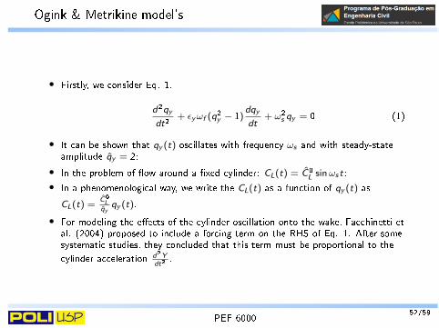
• Firstly, we consider Eq. 1.
d2qy
dt2+ εyωf (q2y − 1)
dqy
dt+ ω2s qy = 0 (1)
• It can be shown that qy (t) oscillates with frequency ωs and with steady-stateamplitude qy = 2;
• In the problem of �ow around a �xed cylinder: CL(t) = C0L sinωs t;
• In a phenomenological way, we write the CL(t) as a function of qy (t) as
CL(t) =C0
Lqy
qy (t).
• For modeling the e�ects of the cylinder oscillation onto the wake, Facchinetti etal. (2004) proposed to include a forcing term on the RHS of Eq. 1. After somesystematic studies, they concluded that this term must be proportional to the
cylinder acceleration d2Ydt2
.
52/59PEF 6000

Ogink & Metrikine model's
• Structural oscillator (hydrodynamic force Fy is decomposed onto two terms, oneassociated with potential �ow - added mass e�ect - and a second one thataccounts the viscous e�ects). Within this framework, the hydro-elastic system isgoverned by:
Md2Y
dt2+ cy
dY
dt+ kyY = Fv,y + Fp =
1
2ρU2∞DLCy,v −mpot
ad2Y
dt2(2)
d2qy
dt2+ εyωf (q2y − 1)
dqy
dt+ ω2f qy =
Ay
D
d2Y
dt2(3)
• We write the mathematical model in the dimensionless form. For this, consider
ωn,y = 2πfn,y =
√ky
M + mpota
, ζy =cy
2(M + mpota )ωn,y
,Ur =U∞
fn,yD
y =Y
D, τ = ωn,y t,
d( )
dt= ωn,y
˙( ),m∗ = 4M
ρπD2L, Cpot
a = 4mpot
a
ρπD2L(4)
• In these notes, Ur and VR are the same quantity.
53/59PEF 6000

Ogink & Metrikine model's
• Using ( ) = d( )dτ
, the dimensionless mathematical model reads
y + 2ζy y + y =1
2π3U2r
(m∗ + Cpota )
Cy,v (5)
qy + εyStUr (q2y − 1)qy + (StUr )2qy = Ay y (6)
• Now, we discuss how to obtain Cy,v . For this, consider the following �gure
𝑈∞
Cilindro desloca-se para baixo
−𝑑𝑌
𝑑𝑡
𝑈𝛽
𝑋
𝑌
𝛽𝐹𝐷,𝑣
𝐹𝐿,𝑣𝐹𝑦,𝑣
𝐹𝑥,𝑣
Extracted from Franzini (2019).
54/59PEF 6000

Ogink & Metrikine model's
• In the model proposed by Facchinetti et al (2004) (and, some years latter,readdressed in Ogink & Metrikine (2010)), the viscous forces are obtainedconsidering the relative velocity between the cylinder and the �uid U and theforce coe�cients obtained in the �ow around a �xed cylinder;
• From the above �gure, we have:
Fv,y =1
2ρU2∞DLCy,v = FL,v cosβ + FD,v sinβ (7)
FD,v =1
2ρU2DLCD,v (8)
FL,v =1
2ρU2DLCL,v (9)
U =
√U2∞ +
(dY
dt
)2= U∞
√1 +
(2πy
Ur
)2(10)
sinβ =− dY
dt
U= −
Dωn y
U∞
√1 +
(DωnU∞
y)2 = −
2πy
Ur
√1 +
(2πyUr
)2 (11)
cosβ =U∞
U=
1√1 +
(2πyUr
)2 (12)
55/59PEF 6000

Ogink & Metrikine model's
• Hence, we conclude that
Cy,v =
(U
U∞
)2(CL,v cosβ + CD,v sinβ) =CL,v
1√1 +
(2πyUr
)2 − CD,v
Ur
2πy√1 +
(2πyUr
)2(1 +
(2πy
Ur
)2)(13)
• In a more compact form:
Cy,v =
(CL,v −
CD,v
Ur2πy
)√1 +
(2πy
Ur
)2(14)
• From the force coe�cients associated with the �ow around a �xed cylinder,CD,v = C0
D (�classical� mean drag coe�cient) and
CL,v =qy
qyC0L (15)
56/59PEF 6000

Ogink & Metrikine model's
• The �nal version of the mathematical model is
y + 2ζy y + y =1
2π3U2r
(m∗ + Cpota )
(qy
qyC0L −
CD,v2πy
Ur
)√1 +
(2πy
Ur
)2(16)
qy + εyStUr (q2y − 1)qy + (StUr )2qy = Ay y (17)
• Ay and εy are coe�cients that must be empirically calibrated;
• In Ogink & Metrikine (2010), the authors obtain another dimensionlessmathematical model because they adopted as dimensionless time τ = tU∞/D.
57/59PEF 6000

Facchinetti and co-authors model's
• Assumed hypothesis: The cylinder velocity dYdt
is much smaller than thefree-stream velocity U∞. Mathematically, the authors assumed that
2π
Ury << 1 (18)
• Using the above hypothesis, the dimensionless mathematical model developed inFacchinetti et al (2004) reads:
y +
(2ζy +
CD,vUr
π2(m∗ + Cpota )
)y + y =
1
2π3U2r
(m∗ + Cpota )
C0L
qyqy (19)
qy + εyStUr (q2y − 1)qy + (StUr )2qy = Ay y (20)
• In Facchinetti et al (2004), the dimensionless mathematical model is di�erentdue to the chosen dimensionless time τ = tU∞/D.
58/59PEF 6000

Facchinetti and co-authors model's
• Another di�erence between the wake-oscillator models proposed in Facchinettiet al (2004) and Ogink & Metrikine (2010) is the de�nition of the empiricallycalibrated parameters;
• Facchineeti et al (2004): A single pair of parameters (Ay , εy ) for the wholerange of reduced velocities;
• Ogink & Metrikine (2010): One pair of parameters (Ay , εy ) for the upperbranch and another one for the lower branch.
Facchinetti et al (2004)
Ay 12εy 0.30
C0L 0.30
CD,v = C0D 2
St 0.20
Ogink & Metrikine (2010)
upper branch lower branchAy 4 12εy 0,05 0.7
C0L 0.3842
CD,v = C0D 1.1856
St 0.1932
59/59PEF 6000