voorbeeld preview - · pdf filedit document is een voorbeeld van nen / this document is a...
TRANSCRIPT

IEC 62056-3-1 Edition 1.0 2013-08
INTERNATIONAL STANDARD NORME INTERNATIONALE
Electricity metering data exchange – The DLMS/COSEM suite – Part 3-1: Use of local area networks on twisted pair with carrier signalling Échange des données de comptage de l'électricité – La suite DLMS/COSEM – Partie 3-1: Utilisation des réseaux locaux sur paire torsadée avec signal de porteuse
IEC
620
56-3
-1:2
013
®
Voorbeeld
Preview
Dit document is een voorbeeld van NEN / This document is a preview by NEN
Dit
do
cum
ent
mag
sle
chts
op
een
sta
nd
-alo
ne
PC
wo
rden
gei
nst
alle
erd
. Geb
ruik
op
een
net
wer
k is
alle
en.
toes
taan
als
een
aan
vulle
nd
e lic
enti
eove
reen
kom
st v
oo
r n
etw
erkg
ebru
ik m
et N
EN
is a
fges
lote
n.
Th
is d
ocu
men
t m
ay o
nly
be
use
d o
n a
sta
nd
-alo
ne
PC
. Use
in a
net
wo
rk is
on
ly p
erm
itte
d w
hen
a su
pp
lem
enta
ry li
cen
se a
gre
emen
t fo
r u
s in
a n
etw
ork
wit
h N
EN
has
bee
n c
on
clu
ded
.

THIS PUBLICATION IS COPYRIGHT PROTECTED Copyright © 2013 IEC, Geneva, Switzerland All rights reserved. Unless otherwise specified, no part of this publication may be reproduced or utilized in any form or by any means, electronic or mechanical, including photocopying and microfilm, without permission in writing from either IEC or IEC's member National Committee in the country of the requester. If you have any questions about IEC copyright or have an enquiry about obtaining additional rights to this publication, please contact the address below or your local IEC member National Committee for further information. Droits de reproduction réservés. Sauf indication contraire, aucune partie de cette publication ne peut être reproduite ni utilisée sous quelque forme que ce soit et par aucun procédé, électronique ou mécanique, y compris la photocopie et les microfilms, sans l'accord écrit de la CEI ou du Comité national de la CEI du pays du demandeur. Si vous avez des questions sur le copyright de la CEI ou si vous désirez obtenir des droits supplémentaires sur cette publication, utilisez les coordonnées ci-après ou contactez le Comité national de la CEI de votre pays de résidence.
IEC Central Office Tel.: +41 22 919 02 11 3, rue de Varembé Fax: +41 22 919 03 00 CH-1211 Geneva 20 [email protected] Switzerland www.iec.ch
About the IEC The International Electrotechnical Commission (IEC) is the leading global organization that prepares and publishes International Standards for all electrical, electronic and related technologies.
About IEC publications The technical content of IEC publications is kept under constant review by the IEC. Please make sure that you have the latest edition, a corrigenda or an amendment might have been published. Useful links: IEC publications search - www.iec.ch/searchpub The advanced search enables you to find IEC publications by a variety of criteria (reference number, text, technical committee,…). It also gives information on projects, replaced and withdrawn publications. IEC Just Published - webstore.iec.ch/justpublished Stay up to date on all new IEC publications. Just Published details all new publications released. Available on-line and also once a month by email.
Electropedia - www.electropedia.org The world's leading online dictionary of electronic and electrical terms containing more than 30 000 terms and definitions in English and French, with equivalent terms in additional languages. Also known as the International Electrotechnical Vocabulary (IEV) on-line. Customer Service Centre - webstore.iec.ch/csc If you wish to give us your feedback on this publication or need further assistance, please contact the Customer Service Centre: [email protected].
A propos de la CEI La Commission Electrotechnique Internationale (CEI) est la première organisation mondiale qui élabore et publie des Normes internationales pour tout ce qui a trait à l'électricité, à l'électronique et aux technologies apparentées.
A propos des publications CEI Le contenu technique des publications de la CEI est constamment revu. Veuillez vous assurer que vous possédez l’édition la plus récente, un corrigendum ou amendement peut avoir été publié. Liens utiles: Recherche de publications CEI - www.iec.ch/searchpub La recherche avancée vous permet de trouver des publications CEI en utilisant différents critères (numéro de référence, texte, comité d’études,…). Elle donne aussi des informations sur les projets et les publications remplacées ou retirées. Just Published CEI - webstore.iec.ch/justpublished Restez informé sur les nouvelles publications de la CEI. Just Published détaille les nouvelles publications parues. Disponible en ligne et aussi une fois par mois par email.
Electropedia - www.electropedia.org Le premier dictionnaire en ligne au monde de termes électroniques et électriques. Il contient plus de 30 000 termes et définitions en anglais et en français, ainsi que les termes équivalents dans les langues additionnelles. Egalement appelé Vocabulaire Electrotechnique International (VEI) en ligne. Service Clients - webstore.iec.ch/csc Si vous désirez nous donner des commentaires sur cette publication ou si vous avez des questions contactez-nous: [email protected].
Voorbeeld
Preview
Dit document is een voorbeeld van NEN / This document is a preview by NEN

IEC 62056-3-1 Edition 1.0 2013-08
INTERNATIONAL STANDARD NORME INTERNATIONALE
Electricity metering data exchange – The DLMS/COSEM suite – Part 3-1: Use of local area networks on twisted pair with carrier signalling Échange des données de comptage de l'électricité – La suite DLMS/COSEM – Partie 3-1: Utilisation des réseaux locaux sur paire torsadée avec signal de porteuse
INTERNATIONAL ELECTROTECHNICAL COMMISSION
COMMISSION ELECTROTECHNIQUE INTERNATIONALE XE ICS 17.220; 35.110; 91.140.50
PRICE CODE CODE PRIX
ISBN 978-2-8322-1046-8
® Registered trademark of the International Electrotechnical Commission Marque déposée de la Commission Electrotechnique Internationale
®
Warning! Make sure that you obtained this publication from an authorized distributor. Attention! Veuillez vous assurer que vous avez obtenu cette publication via un distributeur agréé.
Voorbeeld
Preview
Dit document is een voorbeeld van NEN / This document is a preview by NEN
– 2 – 62056-3-1 © IEC:2013
CONTENTS
FOREWORD ........................................................................................................................... 7 1 Scope ............................................................................................................................... 9 2 Normative references ....................................................................................................... 9 3 Abbreviations ................................................................................................................. 10 4 General description ........................................................................................................ 11
Basic vocabulary ................................................................................................... 11 4.1 Profiles, layers and protocols ................................................................................ 11 4.2
Overview ................................................................................................... 11 4.2.1 Base profile (without DLMS) ...................................................................... 12 4.2.2 Profile with DLMS ...................................................................................... 12 4.2.3 Profile with DLMS/COSEM ........................................................................ 13 4.2.4
Specification language .......................................................................................... 13 4.3 Communication services for local bus data exchange without DLMS ..................... 13 4.4
Overview ................................................................................................... 13 4.4.1 Remote reading exchange ......................................................................... 14 4.4.2 Remote programming exchange ................................................................ 14 4.4.3 Point to point remote transfer exchange .................................................... 16 4.4.4 Broadcast remote transfer frame ............................................................... 16 4.4.5 Bus initialization frame .............................................................................. 16 4.4.6 Forgotten station call exchange ................................................................. 17 4.4.7 Frame fields .............................................................................................. 17 4.4.8 Principle of the energy remote supply ........................................................ 18 4.4.9
Non-energized station preselection exchange ............................................ 19 4.4.10 Communication exchange after preselection .............................................. 20 4.4.11 Alarm function ........................................................................................... 20 4.4.12
Communication services for local bus data exchange with DLMS .......................... 21 4.5 Systems management ........................................................................................... 22 4.6
5 Local bus data exchange without DLMS ......................................................................... 22 Physical layer ........................................................................................................ 22 5.1
Physical-62056-3-1 protocol ...................................................................... 22 5.1.1 Physical parameters .................................................................................. 23 5.1.2 Timing diagrams ........................................................................................ 25 5.1.3 Physical services and service primitives .................................................... 26 5.1.4 State transitions ........................................................................................ 27 5.1.5 List and processing of errors ..................................................................... 34 5.1.6
Data Link layer ...................................................................................................... 35 5.2 Link-62056-3-1 protocol ............................................................................. 35 5.2.1 Management of exchanges ........................................................................ 35 5.2.2 Data Link services and service primitives .................................................. 35 5.2.3 Data Link parameters ................................................................................ 36 5.2.4 State transitions ........................................................................................ 36 5.2.5 List and processing of errors ..................................................................... 41 5.2.6
Application layer .................................................................................................... 42 5.3 Application-62056-3-1 protocol .................................................................. 42 5.3.1 Application services and service primitives ................................................ 42 5.3.2 Application parameters .............................................................................. 42 5.3.3
Voorbeeld
Preview
Dit document is een voorbeeld van NEN / This document is a preview by NEN
62056-3-1 © IEC:2013 – 3 –
State transitions ........................................................................................ 43 5.3.4 List and processing of errors ..................................................................... 45 5.3.5
6 Local bus data exchange with DLMS .............................................................................. 45 Physical layer ........................................................................................................ 45 6.1 Data Link layer ...................................................................................................... 46 6.2
Link-E/D protocol ....................................................................................... 46 6.2.1 Management of exchanges ........................................................................ 46 6.2.2 Data Link services and service primitives .................................................. 47 6.2.3 Data Link parameters ................................................................................ 47 6.2.4 State transitions ........................................................................................ 48 6.2.5 List and processing of errors ..................................................................... 54 6.2.6
Application layer .................................................................................................... 54 6.3 General ..................................................................................................... 54 6.3.1 Transport sub-layer ................................................................................... 54 6.3.2 Application sub-layer ................................................................................. 54 6.3.3
7 Local bus data exchange with DLMS/COSEM ................................................................. 55 Model .................................................................................................................... 55 7.1 Physical Layer ....................................................................................................... 55 7.2
General ..................................................................................................... 55 7.2.1 Physical Parameters .................................................................................. 55 7.2.2 Speed negotiation...................................................................................... 55 7.2.3 E/COSEM Physical Services and service primitives ................................... 56 7.2.4 State transitions ........................................................................................ 57 7.2.5
Data Link layer ...................................................................................................... 65 7.3 General ..................................................................................................... 65 7.3.1 Identification of data units .......................................................................... 66 7.3.2 Role of the Data Link layer ........................................................................ 66 7.3.3 Management of exchanges ........................................................................ 66 7.3.4 Data Link services and service primitives .................................................. 66 7.3.5 Data Link parameters ................................................................................ 68 7.3.6 State transitions ........................................................................................ 68 7.3.7
Support Manager layer .......................................................................................... 75 7.4 Overview ................................................................................................... 75 7.4.1 Initialisation of the bus ............................................................................... 75 7.4.2 Discover service ........................................................................................ 76 7.4.3 Speed negotiation...................................................................................... 76 7.4.4 Support Manager parameters .................................................................... 76 7.4.5 State transitions ........................................................................................ 77 7.4.6
Transport Layer ..................................................................................................... 78 7.5 General ..................................................................................................... 78 7.5.1 Transport Data Units ................................................................................. 78 7.5.2 State transitions ........................................................................................ 80 7.5.3
Application Layer ................................................................................................... 82 7.6 General ..................................................................................................... 82 7.6.1 Broadcast Management ............................................................................. 82 7.6.2 Management of EventNotifications or InformationReports .......................... 83 7.6.3 Priority Management .................................................................................. 83 7.6.4 Management of releasing Application Associations .................................... 83 7.6.5
8 Local bus data exchange – Hardware ............................................................................. 83
Voorbeeld
Preview
Dit document is een voorbeeld van NEN / This document is a preview by NEN
– 4 – 62056-3-1 © IEC:2013
General ................................................................................................................. 83 8.1 General characteristics .......................................................................................... 83 8.2
Signal transmission at 50 kHz .................................................................... 83 8.2.1 Energy supply signal transmission ............................................................. 84 8.2.2 Simple Secondary Station and multiple Secondary Station ........................ 87 8.2.3
Bus specification ................................................................................................... 88 8.3 General characteristics .............................................................................. 88 8.3.1 Cable characteristics ................................................................................. 88 8.3.2 Wiring ........................................................................................................ 89 8.3.3
Magnetic plug ........................................................................................................ 90 8.4 Function .................................................................................................... 90 8.4.1 Common mechanical characteristics .......................................................... 90 8.4.2 Electrical block diagram with simple plug ................................................... 91 8.4.3 Electrical Block Diagram with energy supply plug ...................................... 92 8.4.4
Functional specifications of Primary Station transmitter (for 50 kHz signal) ........... 93 8.5 Functional specifications of Primary Station receiver (for 50 kHz signal)................ 93 8.6 Functional specification of Secondary Station transmitter (for 50 kHz signal) ......... 94 8.7 Functional specifications of Secondary Station receiver (for 50 kHz signal) ........... 95 8.8
Annex A (normative) Specification language ........................................................................ 97 Annex B (normative) Timing types and characteristics ....................................................... 100 Annex C (normative) List of fatal errors .............................................................................. 102 Annex D (normative) Coding the command code field of frames ......................................... 103 Annex E (normative) Principle of the CRC.......................................................................... 105 Annex F (normative) Random integer generation for response from forgotten stations ....... 106 Annex G (normative) Random number generation for authentication (profile without DLMS) ................................................................................................................................ 107 Annex H (normative) Systems management implementation .............................................. 108 Annex I (informative) Information about exchanges ............................................................ 109 Bibliography ........................................................................................................................ 113 Figure 1 – IEC 62056-3-1 communication profiles ................................................................. 12 Figure 2 – Alarm mechanism................................................................................................. 21 Figure 3 – Exchanges in continuous operation ...................................................................... 25 Figure 4 – Alarm event without any communication in progress ............................................ 25 Figure 5 – Alarm event with a communication in progress ..................................................... 25 Figure 6 – Signal envelope on the bus .................................................................................. 84 Figure 7 – Bus representation ............................................................................................... 85 Figure 8 – Power supply characteristics ................................................................................ 85 Figure 9 – States associated to a session: for selected Secondary station ............................ 86 Figure 10 – States associated to a session: for non-selected Secondary station ................... 86 Figure 11 – Simple and multiple Secondary stations ............................................................. 87 Figure 12 – Equivalent diagram of the test equipment ........................................................... 89 Figure 13 – Ferrite pot and bobbin ........................................................................................ 90 Figure 14 – Associated components of the magnetic plug ..................................................... 91 Figure 15 – Associated components of the energy supply plug ............................................. 92 Figure B.1 – Logical timing type .......................................................................................... 100
Voorbeeld
Preview
Dit document is een voorbeeld van NEN / This document is a preview by NEN
62056-3-1 © IEC:2013 – 5 –
Figure B.2 – Physical timing type ........................................................................................ 100 Figure B.3 – Results processing for timing defined with low and high limits ......................... 101 Figure B.4 – Results processing for timing defined by a nominal value ............................... 101 Figure I.1 – Non-energized station session ......................................................................... 109 Figure I.2 – Remote reading and programming exchanges .................................................. 110 Figure I.3 – Bus initialization ............................................................................................... 111 Figure I.4 – Forgotten station call exchange ........................................................................ 112 Table 1 – Primary Station timing ........................................................................................... 23 Table 2 – Secondary station timing ....................................................................................... 24 Table 3 – Physical services and service primitives ................................................................ 26 Table 4 – Physical-62056-3-1 state transitions: Primary station ............................................ 27 Table 5 – Power supply management state transitions (only for non-energized secondary station) ................................................................................................................ 29 Table 6 – Physical-62056-3-1 state transitions: Secondary station ........................................ 31 Table 7 – Meaning of the states listed in the previous tables ................................................. 32 Table 8 – Definition of the procedures, functions and events classified in alphabetical order ..................................................................................................................................... 33 Table 9 – Error summary table .............................................................................................. 34 Table 10 – Data Link services and service primitives ............................................................ 35 Table 11 – Link-62056-3-1 state transitions: Primary station ................................................. 36 Table 12 – Link-62056-3-1 State transitions: Secondary station ............................................ 39 Table 13 – Meaning of the states listed in the previous tables ............................................... 40 Table 14 – Definition of the procedures and functions classified in alphabetical order ........... 40 Table 15 – Error summary table ............................................................................................ 41 Table 16 – Application services and service primitives .......................................................... 42 Table 17 – Application-62056-3-1 state transitions: Primary station ...................................... 43 Table 18 – Application-62056-3-1 state transitions: Secondary station .................................. 44 Table 19 – Meaning of the states listed in the previous tables ............................................... 44 Table 20 – Definition of the procedures and functions classified in alphabetical order ........... 45 Table 21 – Error summary table ............................................................................................ 45 Table 22 – Data Link services and service primitives ............................................................ 47 Table 23 – Link-E/D state transitions: Primary station ........................................................... 48 Table 24 – Link-E/D state transitions: Secondary station....................................................... 50 Table 25 – Meaning of the states listed in the previous tables ............................................... 52 Table 26 – Definition of the procedures and functions classified in alphabetical order ........... 52 Table 27 – Error summary table ............................................................................................ 54 Table 28 – Client_connect function definition ........................................................................ 54 Table 29 – E/COSEM Physical services and service primitives ............................................. 56 Table 30 – E/COSEM Physical state transitions: Primary station ........................................... 57 Table 31 – Power supply management state transitions (only for non-energized Secondary station) ................................................................................................................ 60 Table 32 – E/COSEM Physical State transitions: Secondary station ...................................... 61 Table 33 – Meaning of the states listed in the previous tables ............................................... 63
Voorbeeld
Preview
Dit document is een voorbeeld van NEN / This document is a preview by NEN
– 6 – 62056-3-1 © IEC:2013
Table 34 – Definition of the procedures, functions and events classified in alphabetical order ..................................................................................................................................... 64 Table 35 – Error summary table ............................................................................................ 65 Table 36 – Data Link services and service primitives ............................................................ 66 Table 37 – DLMS/COSEM Data Link E/D state transitions: Primary station ........................... 68 Table 38 – DLMS/COSEM Link E/D state transitions: Secondary station ............................... 71 Table 39 – Meaning of the states listed in the previous tables ............................................... 73 Table 40 – Definition of the procedures and functions classified in alphabetical order ........... 74 Table 41 – Commands managed by the Support Manager layer ............................................ 75 Table 42 – List of parameters ............................................................................................... 76 Table 43 – Support Manager layer state transitions: Primary station ..................................... 77 Table 44 – Support Manager layer state transitions: Secondary station ................................. 77 Table 45 – Meaning of the states listed in the previous table ................................................ 77 Table 46 – Definition of procedures, functions and events .................................................... 78 Table 47 – Transport services and services primitive ............................................................ 79 Table 48 – Transport state transitions ................................................................................... 80 Table 49 – Meaning of the states listed in the previous table ................................................ 81 Table 50 – Definition of the procedures and functions classified in alphabetical order ........... 82 Table 51 – Primary station transmitter: Tev0 and Tev1 values .............................................. 93 Table 52 – Primary station receiver: Tev0 and Tev1 values .................................................. 94 Table 53 – Secondary station transmitter: Tev0 and Tev1 values .......................................... 94 Table 54 – Secondary station receiver: Tev0 and Tev1 values .............................................. 95 Table C.1 – FatalError error numbers ................................................................................. 102 Table D.1 – Command codes for local bus data exchange .................................................. 103 Table D.2 – Command codes with DLMS and DLMS/COSEM .............................................. 104 Table H.1 – Discovery service............................................................................................. 108 Table H.2 – Service specification ........................................................................................ 108
Voorbeeld
Preview
Dit document is een voorbeeld van NEN / This document is a preview by NEN
62056-3-1 © IEC:2013 – 7 –
INTERNATIONAL ELECTROTECHNICAL COMMISSION ____________
ELECTRICITY METERING DATA EXCHANGE –
THE DLMS/COSEM SUITE –
Part 3-1: Use of local area networks on twisted pair with carrier signalling
FOREWORD 1) The International Electrotechnical Commission (IEC) is a worldwide organization for standardization comprising
all national electrotechnical committees (IEC National Committees). The object of IEC is to promote international co-operation on all questions concerning standardization in the electrical and electronic fields. To this end and in addition to other activities, IEC publishes International Standards, Technical Specifications, Technical Reports, Publicly Available Specifications (PAS) and Guides (hereafter referred to as “IEC Publication(s)”). Their preparation is entrusted to technical committees; any IEC National Committee interested in the subject dealt with may participate in this preparatory work. International, governmental and non-governmental organizations liaising with the IEC also participate in this preparation. IEC collaborates closely with the International Organization for Standardization (ISO) in accordance with conditions determined by agreement between the two organizations.
2) The formal decisions or agreements of IEC on technical matters express, as nearly as possible, an international consensus of opinion on the relevant subjects since each technical committee has representation from all interested IEC National Committees.
3) IEC Publications have the form of recommendations for international use and are accepted by IEC National Committees in that sense. While all reasonable efforts are made to ensure that the technical content of IEC Publications is accurate, IEC cannot be held responsible for the way in which they are used or for any misinterpretation by any end user.
4) In order to promote international uniformity, IEC National Committees undertake to apply IEC Publications transparently to the maximum extent possible in their national and regional publications. Any divergence between any IEC Publication and the corresponding national or regional publication shall be clearly indicated in the latter.
5) IEC itself does not provide any attestation of conformity. Independent certification bodies provide conformity assessment services and, in some areas, access to IEC marks of conformity. IEC is not responsible for any services carried out by independent certification bodies.
6) All users should ensure that they have the latest edition of this publication.
7) No liability shall attach to IEC or its directors, employees, servants or agents including individual experts and members of its technical committees and IEC National Committees for any personal injury, property damage or other damage of any nature whatsoever, whether direct or indirect, or for costs (including legal fees) and expenses arising out of the publication, use of, or reliance upon, this IEC Publication or any other IEC Publications.
8) Attention is drawn to the Normative references cited in this publication. Use of the referenced publications is indispensable for the correct application of this publication.
9) Attention is drawn to the possibility that some of the elements of this IEC Publication may be the subject of patent rights. IEC shall not be held responsible for identifying any or all such patent rights.
International Standard IEC 62056-3-1 has been prepared by IEC technical committee 13: Electrical energy measurement, tariff- and load control.
This first edition cancels and replaces the first edition of IEC 62056-31, issued in 1999, and constitutes a technical revision.
The main technical changes with regard to the previous edition are as follows:
• addition of a profile which makes use of the IEC 62056 DLMS/COSEM Application layer and COSEM object model,
• review of the data link layer which is split into two parts: – a pure Data Link layer; – a “Support Manager” entity managing the communication media;
• ability to negotiate the communication speed, bringing baud rate up to 9 600 bauds.
Voorbeeld
Preview
Dit document is een voorbeeld van NEN / This document is a preview by NEN
– 8 – 62056-3-1 © IEC:2013
The text of this standard is based on the following documents:
FDIS Report on voting
13/1546/FDIS 13/1552/RVD
Full information on the voting for the approval of this standard can be found in the report on voting indicated in the above table.
A list of all parts of IEC 62056 series, published under the general title Electricity metering data exchange – The DLMS/COSEM suite, can be found on the IEC website.
Future standards in this series will carry the new general title as cited above. Titles of existing standards in this series will be updated at the time of the next eidition.
The numbering scheme has changes from IEC 62056-XY to IEC 62056-X-Y. For example, IEC 62056-31 becomes IEC 62056-3-1.
This publication has been drafted in accordance with the ISO/IEC Directives, Part 2.
The committee has decided that the contents of this publication will remain unchanged until the stability date indicated on the IEC web site under "http://webstore.iec.ch" in the data related to the specific publication. At this date, the publication will be
• reconfirmed, • withdrawn, • replaced by a revised edition, or • amended.
Voorbeeld
Preview
Dit document is een voorbeeld van NEN / This document is a preview by NEN

62056-3-1 © IEC:2013 – 9 –
ELECTRICITY METERING DATA EXCHANGE – THE DLMS/COSEM SUITE –
Part 3-1: Use of local area networks on twisted pair
with carrier signalling
1 Scope
This part of IEC 62056 describes three profiles for local bus data exchange with stations either energized or not. For non-energized stations, the bus supplies energy for data exchange.
Three different profiles are supported:
• base profile: this three-layer profile provides remote communication services;
NOTE This first profile has been published in IEC 61142:1993 and became known as the Euridis standard.
• profile with DLMS: this profile allows using DLMS services as specified in IEC 61334-4-41;
NOTE This second profile has been published in IEC 62056-31 Ed. 1.0:1999;
• profile with DLMS/COSEM: this profile allows using the DLMS/COSEM Application layer and the COSEM object model as specified in IEC 62056-5-3 Ed. 1.0:— and in IEC 62056-6-2 Ed. 1.0:— respectively.
The three profiles use the same physical layer and they are fully compatible, meaning that devices implementing any of these profiles can be operated on the same bus.
The transmission medium is twisted pair using carrier signalling and it is known as the Euridis Bus.
2 Normative references
The following documents, in whole or in part, are normatively referenced in this document and are indispensable for its application. For dated references, only the edition cited applies. For undated references, the latest edition of the referenced document (including any amendments) applies.
IEC 61334-4-41:1996, Distribution automation using distribution line carrier systems – Part 4: Data communication protocol – Section 41: Application protocols – Distribution line message specification
IEC 62056-51:1998 Electricity Metering – Data exchange for meter reading, tariff and load control – Part 51: Application Layer Protocols
IEC 62056-5-3 Ed. 1.0:—, Electricity metering data exchange – The DLMS/COSEM suite – Part 5-3: DLMS/COSEM application layer
ISO/IEC 8482:1993, Information technology – Telecommunications and information exchange between systems – Twisted pair multipoint interconnections
EIA 485 – Standard for Electrical Characteristics of Generators and Receivers for Use in Balanced Digital Multipoint Systems
Voorbeeld
Preview
Dit document is een voorbeeld van NEN / This document is a preview by NEN
– 10 – 62056-3-1 © IEC:2013
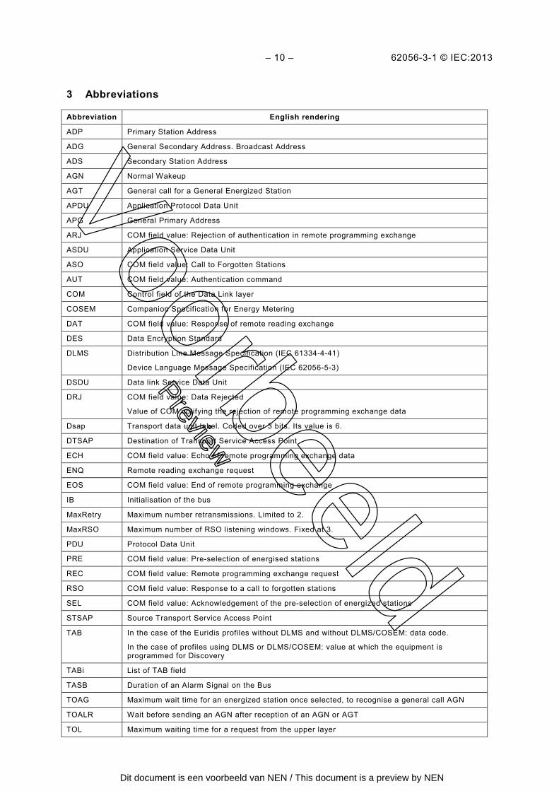
3 Abbreviations
Abbreviation English rendering
ADP Primary Station Address
ADG General Secondary Address. Broadcast Address
ADS Secondary Station Address
AGN Normal Wakeup
AGT General call for a General Energized Station
APDU Application Protocol Data Unit
APG General Primary Address
ARJ COM field value: Rejection of authentication in remote programming exchange
ASDU Application Service Data Unit
ASO COM field value: Call to Forgotten Stations
AUT COM field value: Authentication command
COM Control field of the Data Link layer
COSEM Companion Specification for Energy Metering
DAT COM field value: Response of remote reading exchange
DES Data Encryption Standard
DLMS Distribution Line Message Specification (IEC 61334-4-41)
Device Language Message Specification (IEC 62056-5-3)
DSDU Data link Service Data Unit
DRJ COM field value: Data Rejected
Value of COM notifying the rejection of remote programming exchange data
Dsap Transport data unit label. Coded over 3 bits. Its value is 6.
DTSAP Destination of Transport Service Access Point
ECH COM field value: Echo of remote programming exchange data
ENQ Remote reading exchange request
EOS COM field value: End of remote programming exchange
IB Initialisation of the bus
MaxRetry Maximum number retransmissions. Limited to 2.
MaxRSO Maximum number of RSO listening windows. Fixed at 3.
PDU Protocol Data Unit
PRE COM field value: Pre-selection of energised stations
REC COM field value: Remote programming exchange request
RSO COM field value: Response to a call to forgotten stations
SEL COM field value: Acknowledgement of the pre-selection of energized stations
STSAP Source Transport Service Access Point
TAB In the case of the Euridis profiles without DLMS and without DLMS/COSEM: data code.
In the case of profiles using DLMS or DLMS/COSEM: value at which the equipment is programmed for Discovery
TABi List of TAB field
TASB Duration of an Alarm Signal on the Bus
TOAG Maximum wait time for an energized station once selected, to recognise a general call AGN
TOALR Wait before sending an AGN after reception of an AGN or AGT
TOL Maximum waiting time for a request from the upper layer
Voorbeeld
Preview
Dit document is een voorbeeld van NEN / This document is a preview by NEN
62056-3-1 © IEC:2013 – 11 –
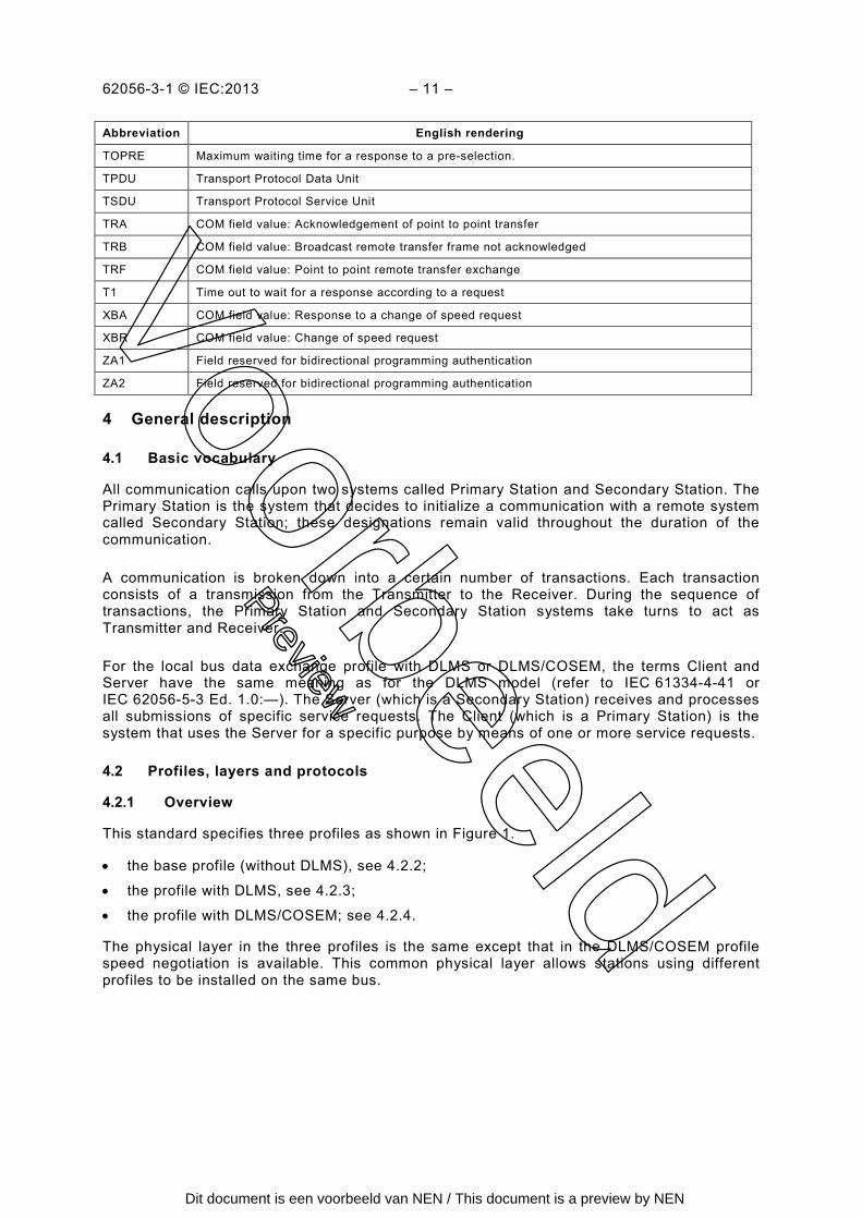
Abbreviation English rendering
TOPRE Maximum waiting time for a response to a pre-selection.
TPDU Transport Protocol Data Unit
TSDU Transport Protocol Service Unit
TRA COM field value: Acknowledgement of point to point transfer
TRB COM field value: Broadcast remote transfer frame not acknowledged
TRF COM field value: Point to point remote transfer exchange
T1 Time out to wait for a response according to a request
XBA COM field value: Response to a change of speed request
XBR COM field value: Change of speed request
ZA1 Field reserved for bidirectional programming authentication
ZA2 Field reserved for bidirectional programming authentication
4 General description
Basic vocabulary 4.1
All communication calls upon two systems called Primary Station and Secondary Station. The Primary Station is the system that decides to initialize a communication with a remote system called Secondary Station; these designations remain valid throughout the duration of the communication.
A communication is broken down into a certain number of transactions. Each transaction consists of a transmission from the Transmitter to the Receiver. During the sequence of transactions, the Primary Station and Secondary Station systems take turns to act as Transmitter and Receiver.
For the local bus data exchange profile with DLMS or DLMS/COSEM, the terms Client and Server have the same meaning as for the DLMS model (refer to IEC 61334-4-41 or IEC 62056-5-3 Ed. 1.0:—). The Server (which is a Secondary Station) receives and processes all submissions of specific service requests. The Client (which is a Primary Station) is the system that uses the Server for a specific purpose by means of one or more service requests.
Profiles, layers and protocols 4.2
Overview 4.2.1
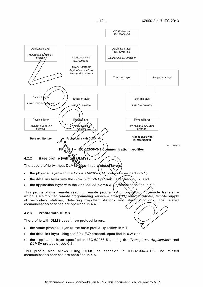
This standard specifies three profiles as shown in Figure 1.
• the base profile (without DLMS), see 4.2.2;
• the profile with DLMS, see 4.2.3;
• the profile with DLMS/COSEM; see 4.2.4.
The physical layer in the three profiles is the same except that in the DLMS/COSEM profile speed negotiation is available. This common physical layer allows stations using different profiles to be installed on the same bus.
Voorbeeld
Preview
Dit document is een voorbeeld van NEN / This document is a preview by NEN
– 12 – 62056-3-1 © IEC:2013
Figure 1 – IEC 62056-3-1 communication profiles
Base profile (without DLMS) 4.2.2
The base profile (without DLMS) uses three protocol layers:
• the physical layer with the Physical-62056-3-1 protocol specified in 5.1;
• the data link layer with the Link-62056-3-1 protocol, specified in 5.2, and
• the application layer with the Application-62056-3-1 protocol specified in 5.3.
This profile allows remote reading, remote programming, point-to-point remote transfer – which is a simplified remote programming service – broadcast remote transfer, remote supply of secondary stations, detecting forgotten stations and alarm functions. The related communication services are specified in 4.4.
Profile with DLMS 4.2.3
The profile with DLMS uses three protocol layers:
• the same physical layer as the base profile, specified in 5.1;
• the data link layer using the Link-E/D protocol, specified in 6.2; and
• the application layer specified in IEC 62056-51, using the Transport+, Application+ and DLMS+ protocols, see 6.3.
This profile also allows using DLMS as specified in IEC 61334-4-41. The related communication services are specified in 4.5.
Application layer
Application-62056-3-1 protocol Application layer
IEC 62056-51
DLMS+ protocolApplication+ protocolTransport + protocol
Application layerIEC 62056-5-3
DLMS/COSEM protocol
COSEM modelIEC 62056-6-2
Data link layer
Link-62056-3-1 protocol
Physical layer
Physical-62056-3-1 protocol
Physical layer
Physical-62056-3-1 protocol
Physical layer
Physical E/COSEM protocol
Data link layer
Link-E/D protocol
Data link layer
Link-E/D protocol
Transport layer Support manager
Base architecture Architecture with DLMS Architecture with DLMS/COSEM
IEC 2066/13
Voorbeeld
Preview
Dit document is een voorbeeld van NEN / This document is a preview by NEN
62056-3-1 © IEC:2013 – 13 –
Profile with DLMS/COSEM 4.2.4
The profile with DLMS/COSEM uses four protocol layers:
• the physical layer, similar to the one used in the base profile and the profile with DLMS, specified in 5.1, but with speed negotiation, see 7.2;
• the data link layer using the Link-E/D protocol. This is the same as the data link layer of the profile with DLMS, except that it interfaces with the support manager layer and the transport layer. See 7.3;
• the support manager layer supports some specific process for the management of the bus, see 0;
• the transport layer provides segmentation and reassembly of APDUs, see 0;
• the application layer as specified in IEC 62056-5-3 Ed. 1.0:—taking into account some restrictions of the Euridis bus, see 0.
The profile with DLMS/COSEM allows using the COSEM object model and the DLMS services accessing the COSEM objects over the Euridis bus.
Specification language 4.3
In this standard, the protocol of each layer is described by state transitions represented in the form of tables. The syntax used in making up these tables is defined by a specification language described in Annex A.
In the event of a difference in interpretation between part of the text and a state transition table, the table is always taken as the reference.
Communication services for local bus data exchange without DLMS 4.4
Overview 4.4.1
The list of available services at the Application level layer is:
a) remote reading of data, see 0; b) remote programming of data, see 4.4.3; c) point to point remote transfer, which is a simplified remote programming service, see
4.4.4; d) broadcast remote transfer, 4.4.5; e) bus initialization, 4.4.6; f) forgotten station call, 4.4.7.
Voorbeeld
Preview
Dit document is een voorbeeld van NEN / This document is a preview by NEN
NEN Standards Products & Servicest.a.v. afdeling KlantenserviceAntwoordnummer 102142600 WB Delft
Wilt u deze norm in PDF-formaat? Deze bestelt u eenvoudig via www.nen.nl/normshop
Gratis e-mailnieuwsbrievenWilt u op de hoogte blijven van de laatste ontwikkelingen op het gebied van normen,
normalisatie en regelgeving? Neem dan een gratis abonnement op een van onze
e-mailnieuwsbrieven. www.nen.nl/nieuwsbrieven
Gegevens Bedrijf / Instelling
T.a.v. O M O V
Klantnummer NEN
Uw ordernummer BTW nummer
Postbus / Adres
Postcode Plaats
Telefoon Fax
Factuuradres (indien dit afwijkt van bovenstaand adres)
Postbus / Adres
Postcode Plaats
Datum Handtekening
NEN Standards Products & Services
Postbus 50592600 GB Delft
Vlinderweg 62623 AX Delft
T (015) 2 690 390F (015) 2 690 271
www.nen.nl/normshop
RetournerenFax: (015) 2 690 271
E-mail: [email protected]
Post: NEN Standards Products
& Services,
t.a.v. afdeling Klantenservice
Antwoordnummer 10214,
2600 WB Delft
(geen postzegel nodig).
Voorwaarden• De prijzen zijn geldig
tot 31 december 2016,
tenzij anders aangegeven.
• Alle prijzen zijn excl. btw,
verzend- en handelingskosten
en onder voorbehoud bij
o.m. ISO- en IEC-normen.
• Bestelt u via de normshop een
pdf, dan betaalt u geen
handeling en verzendkosten.
• Meer informatie: telefoon
(015) 2 690 391, dagelijks
van 8.30 tot 17.00 uur.
• Wijzigingen en typefouten
in teksten en prijsinformatie
voorbehouden.
• U kunt onze algemene
voorwaarden terugvinden op:
www.nen.nl/leveringsvoorwaarden.
preview - 2016
Bestelformulier
Normalisatie: de wereld op één lijn.
Stuur naar:
Ja, ik bestel
€ 257.58__ ex. IEC 62056-3-1:2013 en