volvo trucks north america, inc. trucks - home | … 2 tools special tools see the special tool...
TRANSCRIPT

Service BulletinVolvo Trucks North America, Inc.Greensboro, NC USA
Date Group No. Page
3.2002 397 001 1(32)
Trucks
Volvo Link SystemDesign and Troubleshooting
Satellite Communication System
W3004840
Volvo Link ECU
The Volvo Link System provides satellite communications between a driver and fleet. Itincludes the Volvo Link ECU, GPS antenna, cable, and wiring harnesses. Some vehi-cles also include a dash switch. This system allows communications between Volvo’sWeb based (fleet) software and the vehicle.
This information includes design and troubleshooting of the vehicle portion of the sys-tem. For repair procedures, see service procedures in group 397. For fleet softwaretroubleshooting, see the software help file.
This information contains:
• “System Operation” page 3• “Simplified Schematic” page 12• “System Definitions” page 13• “MID 142 Satellite Communication” page 14
PV776-TSP156441 USA10063

Page 2
ToolsSpecial ToolsSee the special tool information in group 08 for orderinginstructions.
J-39200Fluke Multimeter
J-4323430-pin Breakout Harness
9998551 with J-4334060-pin Breakout Box with Overlay

Volvo Trucks North America, Inc. Date Group No. Page
Service Bulletin 3.2002 397 001 3(32)
Design and Function
System OperationThe Volvo Link System provides satellite communications between the driver and hisfleet home base. The hardware/software that is installed on the vehicle is discussed inthis bulletin. In order for the fleet home base to utilize the system, it must subscribe toa web based service through Volvo. For information on the web based application andsubscription service, see the Volvo web site at
www.volvotrucks.us.com and look under the “Services” category.
The Volvo Link ECU is programmed differently for Cummins and Volvo engines. At thetime of the original installation in the vehicle, the Volvo Link ECU acquires the VehicleIdentification Number (VIN) of the vehicle in which it is installed. Replacement of theECU with one from another vehicle will not work. System checks within the ECU soft-ware will recognize that the ECU is not in the proper vehicle and generate a notificationmessage. The Volvo Link ECU is connected to the J1587/1708 Information Data Link.
Incoming and outgoing messages are read on the instrument cluster graphic displayscreen. Messages are sent and received through the vehicle’s radio antenna system.The vehicle location is identified through a Global Positioning System (GPS) antennalocated in the passenger side mirror head. The ORBCOMM network of Low-Earth Orbitsatellites relays information between the vehicle and fleet.
Some vehicles may be equipped with a “Volvo Action Service” switch that, when acti-vated, will send a message to Volvo requesting assistance and providing the vehiclelocation.

Page 4
System Diagram
W3004841
Volvo Link System
A Multiplex Whip Antennas
B RAMI Antenna Multiplexer box
C GPS Antenna
D* Volvo Action Service Dash Switch
E* Switch Illumination
F Radio
*Switch is not available in all vehicles.
Volvo Trucks North America, Inc. Date Group No. Page
Service Bulletin 3.2002 397 001 5(32)
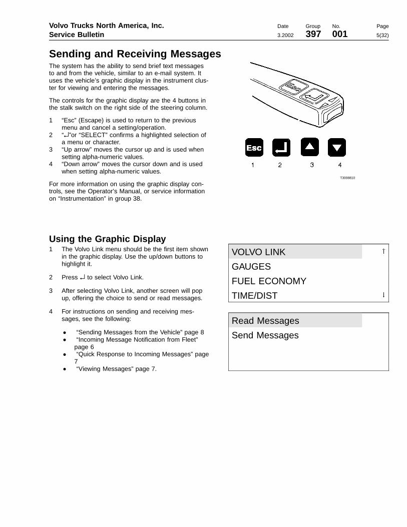
Sending and Receiving MessagesThe system has the ability to send brief text messagesto and from the vehicle, similar to an e-mail system. Ituses the vehicle’s graphic display in the instrument clus-ter for viewing and entering the messages.
The controls for the graphic display are the 4 buttons inthe stalk switch on the right side of the steering column.
1 “Esc” (Escape) is used to return to the previousmenu and cancel a setting/operation.
2 “↵”or “SELECT” confirms a highlighted selection ofa menu or character.
3 “Up arrow” moves the cursor up and is used whensetting alpha-numeric values.
4 “Down arrow” moves the cursor down and is usedwhen setting alpha-numeric values.
For more information on using the graphic display con-trols, see the Operator’s Manual, or service informationon “Instrumentation” in group 38.
T3008810
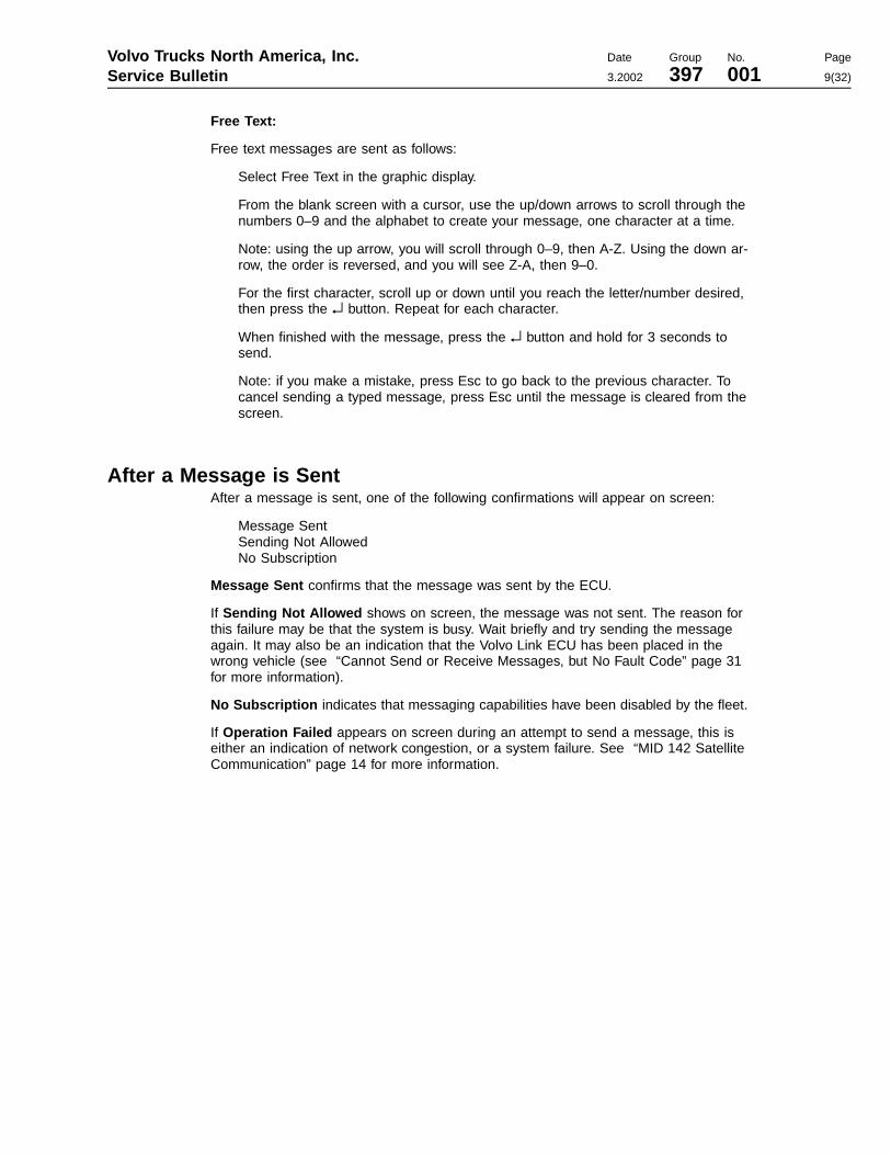
Using the Graphic Display1 The Volvo Link menu should be the first item shown
in the graphic display. Use the up/down buttons tohighlight it.
2 Press ↵ to select Volvo Link.
3 After selecting Volvo Link, another screen will popup, offering the choice to send or read messages.
4 For instructions on sending and receiving mes-sages, see the following:
• “Sending Messages from the Vehicle” page 8• “Incoming Message Notification from Fleet”
page 6• “Quick Response to Incoming Messages” page
7• “Viewing Messages” page 7.
VOLVO LINK "
GAUGES
FUEL ECONOMY
TIME/DIST #
Read Messages
Send Messages

Page 6
Incoming Message Notification from FleetMessages are received at the vehicle from the fleet operator. When a message is re-ceived by the Volvo Link ECU, the driver will be notified with the INFO lamp and amessage in the instrument cluster’s graphic display. The message will appear one ofthe two following ways:
New Message in Volvo LinkorPriority Message in Volvo Link
If in a driving situation where it is safe to do so, the driver can press the Esc buttonwhen he/she sees the message.
Pressing the Esc button turns off the INFO lamp.
The driver can read the “New Message” the next time he stops the vehicle. Or thedriver can read a “Priority Message” while driving, provided the vehicle speed is below55 mph.

Volvo Trucks North America, Inc. Date Group No. Page
Service Bulletin 3.2002 397 001 7(32)
Viewing MessagesTo view all stored messages, select “Volvo Link,” then “Read Messages” in the cluster’sgraphic display.
The messages will display, one at a time, with the most recent message shown first.
Once the newest message is displayed, the driver can use the Up/Down buttons toscroll through the other messages.
Up goes to the next (newer) message. If the newest message is being displayed, theUp button wraps back to the oldest message.
Down goes to the previous (older) message. If the oldest message is being displayed,the Down button wraps back to the newest message.
The message buffer will hold 5 messages. If the buffer is full and a new message is re-ceived, the oldest message will be deleted.
While the vehicle is moving, the last message received is the only one that can be dis-played, and only if it is a “Priority Message.”
If the driver has access or priority to see the message while driving, the message isdisplayed. If not, the driver will see a message directing him to:
Stop Vehicle to Read Message
Quick Response to Incoming MessagesThe driver has the option of a Quick Response to the most recent message in thequeue.
The quick response can be sent while driving.
From the message display screen, press ↵ to access the Quick Response menu.
The Quick Response uses pre-defined text:
Yes/OKNoRespond @ Next Stop

Page 8
Sending Messages from the VehicleThe driver of the vehicle can send messages from the vehicle to the fleet. Messagescan be sent when the vehicle is stopped, but not while it is moving. If you attempt tosend a message when the vehicle is moving, an error message will display, and themessage will not be sent.
The driver can send 3 types of messages, as shown below. These options are se-lectable from the graphic display.
• Defined Text• Breakdown• Free Text
The Defined and Breakdown message lists have approximately 10 message optionswithin each menu.
Defined Text messages:
Load picked upLoad deliveredLate: less than 1 hLate: more than 1 hCompany defined 1Company defined 2Company defined 3Company defined 4Company defined 5
Breakdown messages:
This allows the driver to send breakdown messages along with the vehicle’s GPS loca-tion back to his fleet, which can then help the driver by sending a service vehicle to hislocation.
Towing neededTractor tireTractor electricalTractor air supplyTractor drive trainTractor othersTrailer tireTrailer electricalTrailer air supplyTrailer axlesTrailer others
Volvo Trucks North America, Inc. Date Group No. Page
Service Bulletin 3.2002 397 001 9(32)
Free Text:
Free text messages are sent as follows:
Select Free Text in the graphic display.
From the blank screen with a cursor, use the up/down arrows to scroll through thenumbers 0–9 and the alphabet to create your message, one character at a time.
Note: using the up arrow, you will scroll through 0–9, then A-Z. Using the down ar-row, the order is reversed, and you will see Z-A, then 9–0.
For the first character, scroll up or down until you reach the letter/number desired,then press the ↵ button. Repeat for each character.
When finished with the message, press the ↵ button and hold for 3 seconds tosend.
Note: if you make a mistake, press Esc to go back to the previous character. Tocancel sending a typed message, press Esc until the message is cleared from thescreen.
After a Message is SentAfter a message is sent, one of the following confirmations will appear on screen:
Message SentSending Not AllowedNo Subscription
Message Sent confirms that the message was sent by the ECU.
If Sending Not Allowed shows on screen, the message was not sent. The reason forthis failure may be that the system is busy. Wait briefly and try sending the messageagain. It may also be an indication that the Volvo Link ECU has been placed in thewrong vehicle (see “Cannot Send or Receive Messages, but No Fault Code” page 31for more information).
No Subscription indicates that messaging capabilities have been disabled by the fleet.
If Operation Failed appears on screen during an attempt to send a message, this iseither an indication of network congestion, or a system failure. See “MID 142 SatelliteCommunication” page 14 for more information.
Page 10
Vehicle Log DataTotal miles, Total Idle Fuel used, Total Fuel used, Total Engine Idle hours, Total Enginehours, Vehicle Location (GPS).
This data can be requested by the Web or can be set up in the Volvo Link ECU to besent at predetermined time intervals.
Data is recorded using the J1587/1708 data link on the vehicle.

Volvo Trucks North America, Inc. Date Group No. Page
Service Bulletin 3.2002 397 001 11(32)
ECU Pinout
W3004839
Volvo Link ECU
Pin Name Description
1 BATT+ Battery Supply (+)
2 BATT- Battery Supply (-)
4 OUTPUT1 Volvo Action Service Dash Switch Illumination (not availablein all vehicles)
14 J1587/1708+ J1587/1708 Data Link +
15 INPUT1 (PWR) Ignition Supply (+)
19 INPUT5 (GND) Volvo Action Service Dash Switch (not available in all vehi-cles)
30 J1587/1708- J1587/1708 Data Link -
NOTE: Pins 3, 5–13, 16–18 and 20–29 are not used.
Page 12
Simplified Schematic
W3005010
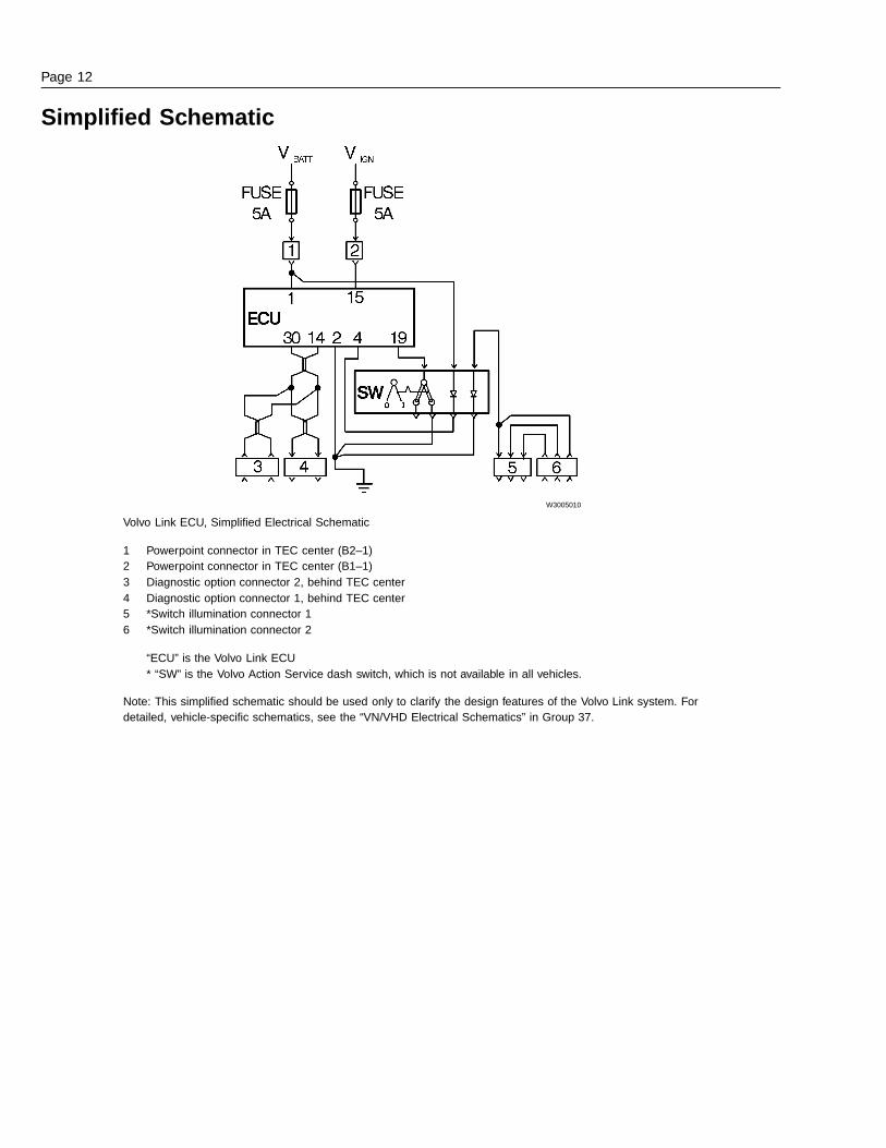
Volvo Link ECU, Simplified Electrical Schematic
1 Powerpoint connector in TEC center (B2–1)2 Powerpoint connector in TEC center (B1–1)3 Diagnostic option connector 2, behind TEC center4 Diagnostic option connector 1, behind TEC center5 *Switch illumination connector 16 *Switch illumination connector 2
“ECU” is the Volvo Link ECU* “SW” is the Volvo Action Service dash switch, which is not available in all vehicles.
Note: This simplified schematic should be used only to clarify the design features of the Volvo Link system. Fordetailed, vehicle-specific schematics, see the “VN/VHD Electrical Schematics” in Group 37.

Volvo Trucks North America, Inc. Date Group No. Page
Service Bulletin 3.2002 397 001 13(32)
System DefinitionsData link An electrical connection for
communication with othermicroprocessor-based de-vices (such as powertraincontrol, trip recorders andmaintenance systems) thatare compatible with the ATAand SAE standard.
GPS Global Positioning System: asystem that uses satellites toprovide users with GPS loca-tion anywhere in the world.
ORBCOMM Satellite communicationsprovider used for Volvo Linksystem. Part of the Volvo LinkECU may be referred to asthe ORBCOMM module, be-cause it is the modulecontaining the satellite com-munications circuitry.
PSID PSID is a Volvo ProprietarySID, or System Identifier. Notethat PSID’s will only show anumeric value in the graphicdisplay – no text description.
Volvo Link Volvo Link System. A satellitecommunciation system inte-grated into Volvo vehicles. Itincludes the Volvo Link ECU,GPS antenna and wiring har-nesses. This system allowscommunications between thefleet (via Volvo’s Web basedsoftware) and the vehicle.
Web World Wide Web or Internet.
Web Application General definition is softwareon the Internet, but in thiscase, it refers to the VolvoLink software, usually admin-istered at a fleet’s home base.

Page 14
TroubleshootingMID 142 Satellite Communication
For Fault Based troubleshooting, see:
• “Fault Code Troubleshooting” page 15
For Symptom Based troubleshooting, see:
• “Troubleshooting the Messages Shown in the Graphic Display” page 29
• “Cannot Send or Receive Messages, but No Fault Code” page 31
• “No Response from Vehicle” page 31
• “Antenna Checks” page 32

Volvo Trucks North America, Inc. Date Group No. Page
Service Bulletin 3.2002 397 001 15(32)
Fault Code TroubleshootingThe system has several failure conditions that can be detected by the ECU. Some ofthese conditions could be loss of data link and signals, output failures and GPS failures.
The fault codes can be read by using the instrument cluster graphic display or VCADSPro.
NOTE: About Inactive Faults: Low Counts - If the count of an inactive fault is low oronly one, then this may indicate a possible system glitch that may not need any correc-tive action.
High Counts - If the count of an inactive fault is high, this may indicate a problem inconcerned or related components and wiring/connectors.
Do not automatically replace any component until it has been verified to be bad.Clear the fault and do the recommended checks as if the fault was active. Also, if pos-sible, try to recreate the fault by placing the vehicle or component in similar conditionsthat may have originally caused the fault. This will help in determining why the faultwas initially logged and also in finding a solution.
NOTE: The descriptions in the table below are the FMI descriptions according to SAEstandards. The text actually shown in the graphic display or in VCADS Pro may varyslightly.
Fault Code: PIDs Function FMI Check
MID 142 - PID 84 Road Speed 9=data not received/abnormalupdate rate
Speed sensor or data link fail-ure. See “Engine Faults” page18.
MID 142 - PID 89 PTO Status 9=data not received/abnormalupdate rate
Indicates a problem in the en-gine system. See “EngineFaults” page 18.
3=voltage shorted high
4=voltage shorted low
MID 142 - PID 155 Output 1-4
5=current low or open circuit
See “MID 142 PID 154 or 155Auxiliary Input and Output Sta-tus” page 20.
MID 142 - PID 155 Input 1-4 12=bad component See “MID 142 PID 154 or 155Auxiliary Input and Output Sta-tus” page 20.
MID 142 - PID 154 Input 5-8 12=bad component See “MID 142 PID 154 or 155Auxiliary Input and Output Sta-tus” page 20.
MID 142 - PID 183 Fuel Rate 9=data not received/abnormalupdate rate
Indicates a problem in the en-gine system. See “EngineFaults” page 18.
MID 142 - PID 190 Engine Speed 9=data not received/abnormalupdate rate
Indicates a problem in the en-gine system. See “EngineFaults” page 18.
MID 142 - PID 235 Idle Engine Hours 9=data not received/abnormalupdate rate
Indicates a problem in the en-gine system. See “EngineFaults” page 18.
MID 142 - PID 236 Idle Fuel Used 9=data not received/abnormalupdate rate
Indicates a problem in the en-gine system. See “EngineFaults” page 18.
MID 142 - PID 237 External VIN Missing 9=data not received/abnormalupdate rate
See “MID 142 PID 237 FMI 9External VIN Missing” page21.

Page 16
Fault Code: PIDs Function FMI Check
MID 142 - PID 245 Odometer 9=data not received/abnormalupdate rate
See “MID 142 PID 245 FMI 9Total Vehicle Distance(Odometer)” page 22
MID 142 - PID 247 Engine Hours 9=data not received/abnormalupdate rate
Indicates a problem in the en-gine system. See “EngineFaults” page 18.
MID 142 - PID 248 PTO Hours 9=data not received/abnormalupdate rate
Indicates a problem in the en-gine system. See “EngineFaults” page 18.
MID 142 - PID 250 Fuel Used 9=data not received/abnormalupdate rate
Indicates a problem in the en-gine system. See “EngineFaults” page 18.
Fault Code: SIDs Function FMI Check
MID 142 - SID 240 Memory Flash/RAM 12=bad component This indicates a power-uphardware failure in the ECU.See “MID 142 SID 240 FMI 12Memory Flash/RAM” page 23
MID 142 - SID 250 J1708/1587 Data Link 9=data not received/abnormalupdate rate
Indicates a data link fault. See“Composite Fault Codes” page19.
MID 142 - SID 253 Memory ROM 12=bad component This indicates a power-uphardware failure in the ECU“MID 142 SID 253 MemoryROM” page 24.
MID 142 - SID 254 ECU Hardware failure 12=bad component Indicates an ECU fault. See“Composite Fault Codes” page19.
Fault Code: PSIDs Function FMI Check
MID 142 - PSID 003 Sending Message Fail-ure
11=unknown failure,12=badcomponent (see also PSID5,6)
For future use.
MID 142 - PSID 004 GPS module/interface 2=bad GPS antenna, 12=badECU
Power and ground to VolvoLink ECU. See “MID 142PSID 004 FMI 2 GPS An-tenna/Interface” page 25 and“MID 142 PSID 004 FMI 12GPS Module/Interface” page26.
MID 142 - PSID 005 DSP module/interface 12=bad device or antenna For future use.
Volvo Trucks North America, Inc. Date Group No. Page
Service Bulletin 3.2002 397 001 17(32)
Fault Code: PSIDs Function FMI Check
MID 142 - PSID 006 ORBCOMM Satellitemodule/interface
2=bad antenna, 12=bad ECU See “MID 142 PSID 006 FMI2 Orbcomm Satellite Commu-nications Module/Interface”page 27 and “MID 142 PSID006 FMI 12 Orbcomm SatelliteCommunications Mod-ule/Interface” page 28.
MID 142 - PSID 009 J1708/1587 Data LinkMissing
9=data not received/abnormalupdate rate
Check data link wiring. See“MID 142 PSID 009 FMI 9J1587/1708 Data Link Missing”page 28.
NOTE: PSID is a Volvo Proprietary SID. Note thatPSID’s will only show a numeric value in the graphic dis-play – no text description.

Page 18
Engine FaultsThese “engine faults” may be an indication of a fault inthe engine, or in the data link information coming fromthe engine ECU or vehicle ECU.
Check for related faults on MID 128. If a related fault ex-ists for MID 128, the problem is most likely in the enginesystem. For more information about engine fault codetroubleshooting, see service information in group 28.
If there are no related faults on MID 128, the problem ismost likely in the data link wiring or connections betweenthe engine system and the Volvo Link ECU.
Begin checking at the Volvo Link ECU, and the wiringconnecting it to the data link. See the simplifiedschematic.
For in-depth troubleshooting of the data link system, seeservice information in group 371.
W3005011
Volvo Link ECU
OPT 1 Two-pin Data Link Connector
OPT 2 Two-pin Data Link Connector. Seefollowing tables for details.
OPT 1 Data Link Connector
Pin Circuit Description
A 401-B J1587/1708-
B 400-B J1587/1708+
Location: rear of TEC center
OPT 2 Data Link Connector
Pin Circuit Description
A 401-A J1587/1708-
B 400-A J1587/1708+
Location: rear of TEC center

Volvo Trucks North America, Inc. Date Group No. Page
Service Bulletin 3.2002 397 001 19(32)
Composite Fault CodesIf you receive a fault containing SID 250 or 254, youmust first check for other faults using VCADS Pro.
The reason is that a composite fault code, SID 250 or254, is generated when one or more of a group of re-lated fault codes exists. If a composite fault code is seen,it is an indication that a related, more specific fault exists.
For example, data link fault codes are grouped underSID 250. But SID 250 only indicates in a general waythat there is a data link fault. To view the more specificfaults, you must request faults using VCADS Pro or theinstrument cluster.
When faults have been requested, the composite faultwill display, along with the other fault(s). For example,using VCADS Pro, the following faults may be shown:
MID 142–SID 250–FMI 9MID 142–SID 245–FMI 9
In this example the problem lies in SID 245, the outputfrom the odometer, and not in SID 250. SID 250 is onlyshown because SID 245 is a related fault – under the“umbrella” of SID 250.
To summarize,
• SID 250 = composite fault for other missingJ1587/1708 data link items, e.g. VIN, odometer, en-gine hours, etc.
• SID 254 = composite fault for physical hardwareproblems, e.g. Inputs and outputs, GPS/Orbcommantennas, memory, etc.
Display for SID 250:
MID142
SAE J1708 Data Link
Communication Error
Active
Display for SID 254:
MID142
Controller #1
Component Failure
Active
Note: Actual text may vary slightly.

Page 20
MID 142 PID 154 or 155 Auxiliary Input and Output StatusGeneral InformationHardware failure.
Fault codeFMI 3: Voltage shorted high
FMI 4: Voltage shorted low
FMI 5: Voltage low or open circuit
FMI 12: Bad component
• Conditions - ECU did not receive correct input orgenerate correct output.
• Cause - Defective wiring, switch or internal ECUproblem.
• Reaction from control unit - Set Active Fault.
• Noticeable external symptoms - Cluster displaysfault message when queried for faults.
• Checks - Input and Output hardware, per Table. Ifhardware OK, replace ECU.
Special tools: J-39200, J-43340, J-43234, 9998551
• Key switch position: ON• Measuring: Voltage measurement at Truck Elec-
trical Center (TEC) or Volvo Link ECU• Adapter J-43234 to be connected to the blue
JAE connector on the ECU when applicable.Use the 30–pin side of Overlay J-43340.
Fault Code Description Type of Fault Check Expected Value
ECU Output 1 VAS Dash SwitchIllumination (not avail-able in all vehicles)
ECU Output 2 Not used
ECU Output 3 Not used
PID 155, FMI3/4/5
ECU Output 4
Electrical Fault, in-ternal ECU orhardware
Not used
ECU Input 1 Pin 15 - 2 (Ign+) Battery voltage
ECU Input 2 Not used
ECU Input 3 Not used
PID 155, FMI 12
ECU Input 4
Component Failure,internal ECU orhardware
Not used
ECU Input 5 VAS Dash Switch(not available in allvehicles)
ECU Input 6 Not used
ECU Input 7 Not used
PID 154, FMI 12
ECU Input 8
Component Failure,internal ECU orhardware
Not used

Volvo Trucks North America, Inc. Date Group No. Page
Service Bulletin 3.2002 397 001 21(32)
MID 142 PID 237 FMI 9 External VIN Missing
General InformationIndicates missing/incorrect VIN information on the datalink.
Fault codeFMI 9 Abnormal Update Rate
• Conditions - Volvo Link requested VIN informationfrom both the Cluster (MID 234) and Engine(MID128).
• Cause - Volvo Link requested VIN information anddid not receive it due to missing/incorrect data in theECUs.
• Reaction from control unit - Set Active Fault.
• Noticeable external symptoms - Cluster displaysfault message when queried for faults.
• Checks - Perform 1700-08-02-04 Vehicle Informa-tion test in VCADS Pro and correct any mismatchedVIN’s at this time by reprogramming the ECU(s) thatcontain incorrect VIN(s).
NOTE: VCADS Pro will automatically make aware tothe user that one or more ECUs have incorrectVINs. Tests and calibrations are restricted, but pro-gramming can be performed.
W0001632

Page 22
MID 142 PID 245 FMI 9 Total Vehicle Distance (Odometer)
General InformationIndicates a problem in the data link input from the instru-ment cluster.
This data is received from the J1587/1708 datalink aswell as being calculated internally. The internally calcu-lated data is the total accumulated distance the vehiclehas been driven since the installation of the Volvo Linksystem.
Fault codeFMI 9: Abnormal Update Rate
This displays in the instrument cluster as“MID 142, Total Vehicle Dist, Communication Error”
• Conditions - Volvo Link requested odometer data,but did not receive it.
• Cause - If the data is not received this fault code isset.
• Reaction from control unit - Set Active Fault.
• Noticeable external symptoms - Cluster displaysfault message when queried for faults.
• Checks - Check to see if MID 140 responds to1700–08–02–04 Vehicle Information Test in VCADSPro. If MID 140 is present, the data link may haveexperienced congestion problems, which causedthis fault to appear.
If the number of fault instances is low, the faultwas probably caused by data link congestion.No action is needed.If the number of fault instances is high, a datalink / ECU problem exists between the instru-ment cluster and the Volvo Link ECU.
For in-depth troubleshooting of the data link system, seeservice information in group 371.
W3005011
Volvo Link ECU, Data Link Wiring
OPT 1 Two-pin Data Link Connector
OPT 2 Two-pin Data Link Connector
For complete data link wiring, see “VN ElectricalSchematics” in Group 37.

Volvo Trucks North America, Inc. Date Group No. Page
Service Bulletin 3.2002 397 001 23(32)
MID 142 SID 240 FMI 12 Memory Flash/RAM
General InformationThis fault indicates a power-up failure, which is mostlikely an internal ECU problem.
Fault codeFMI 12 Bad Component
This displays in the instrument cluster as“MID142, Program Memory, Component Failure”
• Conditions - Volvo Link ECU performs certain errorchecking and memory functions during power up.
• Cause - Volvo Link ECU detects a failure duringpower up and sets an active fault.
• Reaction from control unit - Set Active Fault, Re-strict operations.
• Noticeable external symptoms
Cluster displays fault message when queried forfaults.
Volvo Link will disable itself and no internal op-erations can be performed. Broadcasting faultmessages is limited to once every 15 sec. Allincoming messages from datalink, ignition,Volvo Action Service switch input, Orbcommand GPS will be ignored.
• Checks - If this fault code is reported, then the VolvoLink ECU is considered to contain fatal errors andthe unit must be replaced.
T2012704

Page 24
MID 142 SID 253 Memory ROM
General InformationThis fault indicates a power-up failure, which is mostlikely an internal ECU problem.
Fault codeFMI 12 Bad Component
This displays in the instrument cluster as“MID142, Calibration Memory, Component Failure”
• Conditions - Volvo Link ECU performs certain errorchecking and memory functions during power up.
• Cause - Volvo Link ECU detects a failure duringpower up and sets an active fault.
• Reaction from control unit - Set Active Fault, Re-strict operations.
• Noticeable external symptoms
Cluster displays fault message when queried forfaults.
Volvo Link will disable itself and no internal op-erations can be performed. Broadcasting faultmessages is limited to once every 15 sec. Allincoming messages from data link, ignition,Volvo Action Service switch input, Orbcommand GPS will be ignored.
• Checks - If this fault code is reported, then the VolvoLink ECU is considered to contain fatal errors andthe unit must be replaced.
T2012704

Volvo Trucks North America, Inc. Date Group No. Page
Service Bulletin 3.2002 397 001 25(32)
MID 142 PSID 004 FMI 2 GPS Antenna/Interface
General InformationThis fault indicates a failure of the GPS antenna, or afailure of the ECU’s GPS receiver circuitry. But it canalso occur if there are no satellite communications, i.e.inside a building or tunnel for a long period of time. Thefault is logged if:
• there are no satellites in view for 10 minutes whilethe vehicle is moving
• or if there are no communications with the GPSmodule portion of the ECU for more than 1 minute.
Check power and ground to Volvo Link ECU. Also checkantenna connections at ECU and GPS antenna.
Fault codeFMI 2 Bad Antenna
This displays in the instrument cluster as“MID142, PSID004, Data Error”
• Conditions - Volvo Link ECU performs certain errorchecking functions during power up.
• Cause - Volvo Link ECU detects a GPS antennafailure while the vehicle is in operation and sets anactive fault.
• Reaction from control unit - Set Active Fault.
• Noticeable external symptoms
Cluster displays fault message when queried forfaults.
• Checks - If this fault code is reported, check theGPS antenna function in an area where there is aclear view of the sky. Does the fault remain active,or become inactive? If inactive and the count of ac-tive faults is one, the system is probably OK. If theinactive fault count is high, or if the fault remains ac-tive, check the GPS module in the mirror housingand the antenna cable from the mirror to the ECU tomake sure that both are functioning correctly. If ei-ther is found to be defective replace as required.
W3005015

Page 26
MID 142 PSID 004 FMI 12 GPS Module/Interface
General InformationThis fault indicates a GPS serial communications failure.An internal GPS error has occurred, either on power-upor during operation. The GPS module is part of theVolvo Link ECU.
Fault codeFMI 12 Bad Component
This displays in the instrument cluster as“MID 142, PSID 004, Component Failure”
• Conditions - Volvo Link ECU performs certain errorchecking functions during power up.
• Cause - Volvo Link ECU detects an internal GPSmodule/interface failure during power up and setsan active fault.
• Reaction from control unit - Set Active Fault.
• Noticeable external symptoms
Cluster displays fault message when queried forfaults.
Volvo Link will disable itself and no internal op-erations can be performed. Broadcasting faultmessages is limited to once every 15 sec. Note:if this fault occurs during operation, there will beno messages broadcast. All incoming mes-sages from datalink, ignition, Volvo ActionService switch input, Orbcomm and GPS will beignored.
• Checks - If this fault code is reported, the Volvo LinkECU is considered to contain fatal errors and shouldbe replaced.
W3005015
Volvo Trucks North America, Inc. Date Group No. Page
Service Bulletin 3.2002 397 001 27(32)
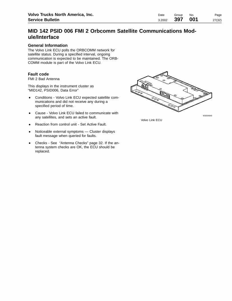
MID 142 PSID 006 FMI 2 Orbcomm Satellite Communications Mod-ule/Interface
General InformationThe Volvo Link ECU polls the ORBCOMM network forsatellite status. During a specified interval, ongoingcommunication is expected to be maintained. The ORB-COMM module is part of the Volvo Link ECU.
Fault codeFMI 2 Bad Antenna
This displays in the instrument cluster as“MID142, PSID006, Data Error”
• Conditions - Volvo Link ECU expected satellite com-munications and did not receive any during aspecified period of time.
• Cause - Volvo Link ECU failed to communicate withany satellites, and sets an active fault.
• Reaction from control unit - Set Active Fault.
• Noticeable external symptoms — Cluster displaysfault message when queried for faults.
• Checks - See “Antenna Checks” page 32. If the an-tenna system checks are OK, the ECU should bereplaced.
W3004840
Volvo Link ECU

Page 28
MID 142 PSID 006 FMI 12 Orbcomm Satellite Communications Mod-ule/Interface
General InformationThe Volvo Link ECU polls the ORBCOMM network forsatellite status. During a specified interval, ongoingcommunication is expected to be maintained. The ORB-COMM module is part of the Volvo Link ECU.
Fault codeFMI 12 Bad Component
This displays in the instrument cluster as“MID142, PSID006, Component Failure”
• Conditions - Volvo Link ECU expected satellite com-munications and did not receive any during aspecified period of time.
• Cause - Volvo Link ECU failed to communicate withany satellites, and sets an active fault.
• Reaction from control unit - Set Active Fault.
• Noticeable external symptoms — Cluster displaysfault message when queried for faults.
• Checks - See antenna checks on “AntennaChecks” page 32. If the antenna system checks areOK, the ECU should be replaced.
W3004840
Volvo Link ECU
MID 142 PSID 009 FMI 9 J1587/1708 Data Link Missing
General InformationIndicates an expected input to the Volvo Link ECU fromthe data link is missing. This indicates the Volvo LinkECU has detected “ignition on” with no data link activity.The data link connection to the Volvo Link ECU shouldbe checked.
For more information see data link troubleshooting infor-mation in group 37.

Volvo Trucks North America, Inc. Date Group No. Page
Service Bulletin 3.2002 397 001 29(32)
Troubleshooting the Messages Shown in the Graphic Display
Operation FailedThis message is displayed during a failure to Send orRead messages from the ECU.
NOTE: This message can be displayed without anyproblems in the system, due to data link congestion.
1 Attempt to Read Messages again. If you do not getthe Operation Failed Screen again, then the prob-lem was data link congestion. Try this 2–3 times justto make sure that there is a problem.
2 Check fault codes. Try to read faults 2–3 times. If arelated fault is shown, see “Fault Code Trou-bleshooting” page 15. Even if a fault is not shown, ahardware failure may exist. Go to the next step.
3 If the problem still occurs and the instrument clusteris working with other data link devices, there may bea hardware failure in the wiring or connections.Make the following checks.
Special tools: J-39200, J-43340, J-43234, 9998551
• Key switch position: ON• Measuring: Voltage measurement at Truck Electrical
Center (TEC) or Volvo Link ECU• Adapter J-43234 to be connected to the blue JAE
connector on the Volvo Link ECU when applicable.Use the 30–pin side of overlay J-43340.
W3005016
Function Check ExpectedValue
Possible Cause Note
Power connec-tions at TEC
Check both power pointconnectors to the expan-sion block positions of theTEC.
Battery Voltage Harness connector not con-nected.Fuse blown/missing.
Data link con-nection at TEC
Check connection at datalink connector at rear ofTEC.
0-5 VDC Harness connector not con-nected.Data link wiring bro-ken/damaged.
To read the fluctua-tion in voltage on thedata link set therange on the DMM tozero decimal places.This should stabilizethe measurement.
Power connec-tions at ECU
Measure voltage at ECU:pins 1-2 (Batt+),pin 15-2 (Ign+)
Battery Voltage If voltage Ok at TEC, thencheck continuity on wiring inquestion from TEC to theECU.
Data Link con-nections atECU
Measure voltage at ECU:pin 14 -30 (J1587+ toJ1587-)pin 14 -2 (J1587+ to gnd)pin 30-2 (J1587- to gnd)
0-5 VDC If voltage Ok at TEC, thencheck continuity on wiring inquestion from TEC to theECU.
To read the fluctua-tion in voltage on thedata link set therange on the DMM tozero decimal places.This should stabilizethe measurement.

Page 30
No SubscriptionThis message is displayed in the cluster when there areno subscriptions programmed in ECU.
The ECU is working properly, but has not been properlyconfigured by the Web site to allow the type of action re-quested.
Stop Vehicle to Read MessageThis message is displayed when the road speed is over 5mph for low priority messages, and over 55 mph for highpriority messages. Or, it may be displayed when scrollingthrough the messages when road speed is above 5 mph.
Sending Not AllowedThis message is displayed in the following conditions:
• when trying a “quick response” to an old message(quick response is only possible with the most re-cent message)
• in other cases where the system will not allow a re-sponse
If you see this message, try to send your message againlater. If you continue to receive this message, see“Cannot Send or Receive Messages, but No Fault Code”page 31.
No Messages AvailableThis message is displayed when the Volvo Link ECU’sincoming message queue is empty.
Message SentThis message is displayed when the Volvo Link ECU hasreceived a message to be sent to the web site. Themessage has been queued and will be sent during nextavailable satellite transmission.
Stop Vehicle to Send MsgThis message is displayed when the cluster detects thevehicle speed is above 5 mph. Vehicle speed must bebelow 5 mph before the cluster will allow you to send amessage.
Volvo Trucks North America, Inc. Date Group No. Page
Service Bulletin 3.2002 397 001 31(32)
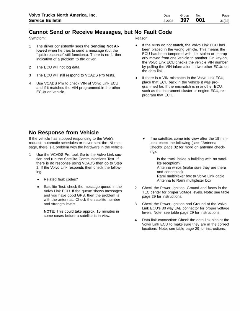
Cannot Send or Receive Messages, but No Fault CodeSymptom:
1 The driver consistently sees the Sending Not Al-lowed when he tries to send a message (but the“quick response” still functions). There is no furtherindication of a problem to the driver.
2 The ECU will not log data.
3 The ECU will still respond to VCADS Pro tests.
4 Use VCADS Pro to check VIN of Volvo Link ECUand if it matches the VIN programmed in the otherECUs on vehicle.
Reason:
• If the VINs do not match, the Volvo Link ECU hasbeen placed in the wrong vehicle. This means theECU has been tampered with: i.e. stolen or improp-erly moved from one vehicle to another. On key-on,the Volvo Link ECU checks the vehicle VIN numberby polling the VIN information in two other ECUs onthe data link.
• If there is a VIN mismatch in the Volvo Link ECU,place that ECU back in the vehicle it was pro-grammed for. If the mismatch is in another ECU,such as the instrument cluster or engine ECU, re-program that ECU.
No Response from VehicleIf the vehicle has stopped responding to the Web’srequest, automatic schedules or never sent the INI mes-sage, there is a problem with the hardware in the vehicle.
1 Use the VCADS Pro tool. Go to the Volvo Link sec-tion and run the Satellite Communications Test. Ifthere is no response using VCADS then go to Step2. If the Volvo Link responds then check the follow-ing.
• Related fault codes?
• Satellite Test: check the message queue in theVolvo Link ECU. If the queue shows messagesand you have good GPS, then the problem iswith the antennas. Check the satellite numberand strength levels.
NOTE: This could take approx. 15 minutes insome cases before a satellite is in view.
• If no satellites come into view after the 15 min-utes, check the following (see “AntennaChecks” page 32 for more on antenna check-ing):
Is the truck inside a building with no satel-lite reception?Antenna whips (make sure they are thereand connected)Rami multiplexer box to Volvo Link cableAntenna to Rami multiplexer box
2 Check the Power, Ignition, Ground and fuses in theTEC center for proper voltage levels. Note: see tablepage 29 for instructions.
3 Check the Power, Ignition and Ground at the VolvoLink ECU’s 30 way JAE connector for proper voltagelevels. Note: see table page 29 for instructions.
4 Data link connection: Check the data link pins at theVolvo Link ECU to make sure they are in the correctlocations. Note: see table page 29 for instructions.

Page 32
Antenna Checks
Preliminary ChecksPhysically verify that the Rami antennas are attached tothe vehicle and are connected to the cables in the mirrorhousings properly. Also verify that there is no damage tothe antenna system. Replace all defective or missingcomponents before continuing with the fault tracing be-low.
Do not attempt to troubleshoot radio/antenna receptionproblems in the following conditions:
• Inside buildings• In areas with a high rate of reflected signal activity
(reflected signals are weaker than direct signals &cause problems with cancellation of the direct sig-nals), which ultimately affects radio reception clarity.
• In areas of electrical interference (such as high ten-sion electrical lines)
• When there are electrical storms nearby
The following checks should be performed if a communi-cation problem exists with the Volvo Link system, andthe antennas are suspected as being the problem. If aproblem is suspected with the radio see Service Infor-mation on the Audio System in group 39.
Basic Reception TestPerform the following checks of the radio signals (AM/FMand Weatherband). Stations should come in clear withno static.
If the radio plays well, the antenna system is OK. If theradio does not play well, then it is reasonable to say thata problem exists in one of the following:
• Radio• Volvo Link ECU• Antenna system
W3005013
Volvo Link ECU and Antenna System
A Multiplex Whip AntennasB RAMI Antenna Multiplexer BoxC GPS AntennaD Antenna Jumper Cable
Check Expected Result Possible Cause
OK Radio and antenna system are OK. Fault may be in theVolvo Link ECU or cables. Check fault codes and test withVCADS Pro.
Reception with antenna con-nected directly to the radio
Not OK Fault may be in the antenna system. See Service Infor-mation on antenna troubleshooting in group 39, "AudioSystem."
Reception with antenna discon-nected from radio
Not OK A difference in reception should be noticed. Use this dif-ference (connected vs disconnected) as a baseline tojudge reception clarity.
OK Radio and Antenna system are OK. Fault is in Volvo LinkECU.
Antenna disconnected from VolvoLink ECU and each end recon-nected to each other (RF Inconnected to RF Out) Not OK The RF IN / RF OUT jumper cables may be defective.