voluntary safety recall campaign 1996 … service campaign has been amended to include additional...
TRANSCRIPT

1/53
Reference: Date:
NTB11-064d January 10, 2012
VOLUNTARY SAFETY RECALL CAMPAIGN 1996-2004 PATHFINDER IN SALT STATES
LEFT FRONT STRUT HOUSING CORROSION
This service campaign has been amended to include additional parts information. No other changes have been made to the body of the bulletin.
CAMPAIGN ID #: R1107 NHTSA #: 11V-244 APPLIED VEHICLES: 1996 – 2004 Pathfinder (R50)
Check Service COMM to confirm campaign eligibility.
INTRODUCTION
Nissan is conducting a voluntary safety recall campaign on certain model year 1996 - 2004 Pathfinder vehicles that are currently registered in States where heavy concentrations of road salt are used in the winter to inspect for corrosion, and if necessary repair the front strut housing panels.
Salt States
Maine, New Hampshire, Vermont, Massachusetts, Rhode Island, Connecticut, New York, New Jersey, Pennsylvania, Delaware, Maryland, West Virginia, Ohio, Indiana, Michigan, Illinois, Wisconsin, Minnesota, Iowa, and Missouri and the District of Columbia.
IDENTIFICATION NUMBER
Nissan has assigned identification number R1107 to this campaign. This number must appear on all communications and documentation of any nature dealing with this campaign.
DEALER RESPONSIBILITY
It is the dealer’s responsibility to check Service Comm for the campaign status on each vehicle falling within the range of this voluntary safety recall which for any reason enters the service department. This includes vehicles purchased from private parties or presented by transient (tourist) owners and vehicles in a dealer’s inventory. Federal law requires that new vehicles in dealer inventory which are the subject of a safety recall must be corrected prior to sale. Failure to do so can result in civil penalties by the National Highway Traffic Safety Administration. While federal law applies only to new vehicles, Nissan strongly encourages dealers to correct any used vehicles in their inventory before they are retailed.
TABLE OF CONTENTS
Page REPAIR OVERVIEW …………………………………………………………..…………... 3 REQUIRED SPECIAL TOOLS ……………………………………………………………. 4 SERVICE PROCEDURE …………………………………………………………………... 5 Determine if Vehicle is Repairable …………………………………………………….. 5 Determine Repair Level (driver side and passenger side) ………………………….. 9 Level 1 Repair (driver side and passenger side) ……………….…………………….. 11 Driver Side - Level 2 Repair ……..……………………………………………………... 13 Strut Removal ………..………………………………………………………………… 13 Repair Bracket Installation ……………………………………………………………. 16 Patching Perforated Areas ……………………………………………………………. 32 Passenger Side - Level 2 Repair ……………………………………………...……….. 39 STEERING SHAFT REPLACEMENT ……………………………………………………. 42 EXAMPLE PHOTOS (perforation and scab corrosion)…………………………………. 46 PARTS INFORMATION ……………………………………………………………………. 48 CLAIMS INFORMATION …………………………………………………………………... 49 OWNER LETTER …………………………………………………………………………… 52 NON REPAIRABLE REPORT …………………………….………………………………. 53
2/53 NTB11-064d

REPAIR OVERVIEW
Use Service Comm (campaign ID # R1107) to confirm the vehicle you’re working on is affected by this campaign
Determine if Vehicle is Repairable (page 5) (Inspect for perforation area 1 and scab corrosion area 2)
Perforation in area 1 NO perforation in area 1
and/or and
Scab corrosion in area 2 NO scab corrosion in area 2
Vehicle is not repairable Vehicle is repairable
1. Retain the vehicle at the dealer.
Determine Repair Level (page 9) and perform needed repairs per
the Service Procedure
2. Supply the customer with a rental car.
Possible Repair Levels
3. Fax a completed Non-Repairable Report to Morley (see page 53).
Use Level 1 Repair If: Use Level 2 Repair If:
Driver Side * No visible rust or only surface rust (page 11)
Any scab corrosion or perforation (page 13)
Passenger Side * No perforation (page11)
Perforation (page 39)
* Refer to summary of each repair level on page 10.
3/53 NTB11-064d
REQUIRED SPECIAL TOOLS
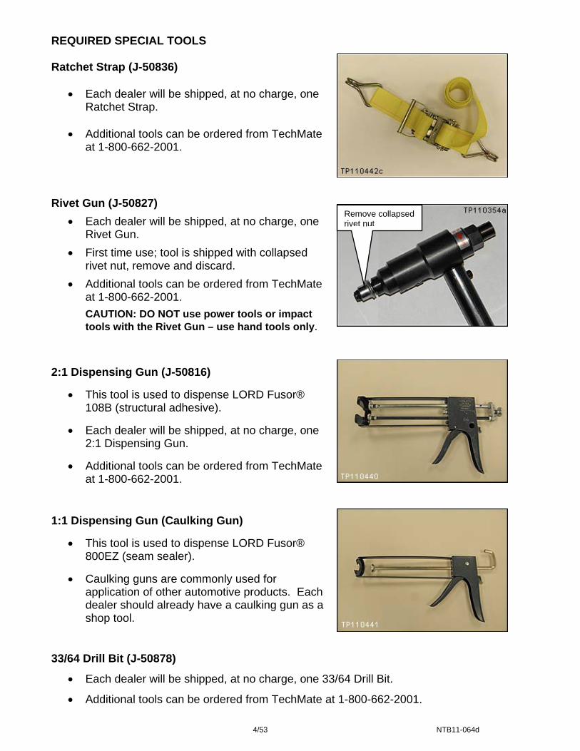
Ratchet Strap (J-50836)
• Each dealer will be shipped, at no charge, one Ratchet Strap.
• Additional tools can be ordered from TechMate
at 1-800-662-2001.
Rivet Gun (J-50827)
• Each dealer will be shipped, at no charge, one Rivet Gun.
• First time use; tool is shipped with collapsed rivet nut, remove and discard.
• Additional tools can be ordered from TechMate at 1-800-662-2001.
CAUTION: DO NOT use power tools or impact tools with the Rivet Gun – use hand tools only.
Remove collapsed rivet nut
2:1 Dispensing Gun (J-50816)
• This tool is used to dispense LORD Fusor® 108B (structural adhesive).
• Each dealer will be shipped, at no charge, one 2:1 Dispensing Gun.
• Additional tools can be ordered from TechMate at 1-800-662-2001.
1:1 Dispensing Gun (Caulking Gun)
• This tool is used to dispense LORD Fusor® 800EZ (seam sealer).
• Caulking guns are commonly used for application of other automotive products. Each dealer should already have a caulking gun as a shop tool.
33/64 Drill Bit (J-50878)
• Each dealer will be shipped, at no charge, one 33/64 Drill Bit.
• Additional tools can be ordered from TechMate at 1-800-662-2001.
4/53 NTB11-064d
SERVICE PROCEDURE
NOTE: This campaign does not cover any repairs beyond those specifically mentioned in this Service Procedure.
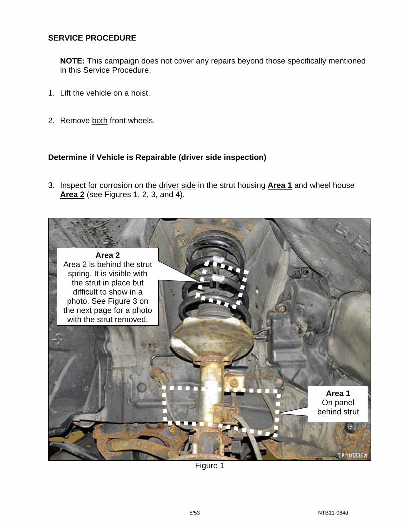
1. Lift the vehicle on a hoist. 2. Remove both front wheels. Determine if Vehicle is Repairable (driver side inspection) 3. Inspect for corrosion on the driver side in the strut housing Area 1 and wheel house
Area 2 (see Figures 1, 2, 3, and 4).
Area 2 Area 2 is behind the strut
spring. It is visible with the strut in place but difficult to show in a
photo. See Figure 3 on the next page for a photo with the strut removed.
Area 1 On panel
behind strut
Figure 1
5/53 NTB11-064d

Strut has been removed to show the areas of inspection.
NOTE: Strut does not need to be removed to perform inspection.
Area 2
Figure 2
Area 1
This photo shows the inspection areas in relation to the repair bracket installation.
Area 2
Figure 2A
Area 1
6/53 NTB11-064d

Area 1
Figure 3
Area of inspection is below this ridge.
Area 1
Example of no perforation (no holes) within the outlined areas.
Area 1: Look for perforation (holes) in the metal only in the areas outlined above.
NOTE: If needed, refer to examples (additional photos) of area 1 perforation inspection on pages 46 and 47.
If there is perforation (holes) in the metal in area 1:
a. Retain the vehicle at the dealer. (The vehicle is not repairable.) b. Supply the customer with a rental car. c. Fax a completed Non-Repairable Report to Morley (see page 53).
If there is no perforation (no holes) in the metal in area 1:
• Go to Area 2 on the next page.
7/53 NTB11-064d
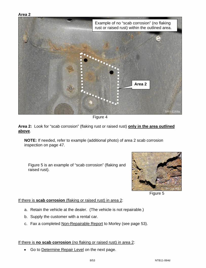
Area 2
Area 2
Example of no “scab corrosion” (no flaking rust or raised rust) within the outlined area.
Figure 4 Area 2: Look for “scab corrosion” (flaking rust or raised rust) only in the area outlined above.
NOTE: If needed, refer to example (additional photo) of area 2 scab corrosion inspection on page 47.
Figure 5 is an example of “scab corrosion” (flaking and raised rust).
Figure 5
If there is scab corrosion (flaking or raised rust) in area 2:
a. Retain the vehicle at the dealer. (The vehicle is not repairable.)
b. Supply the customer with a rental car.
c. Fax a completed Non-Repairable Report to Morley (see page 53).
If there is no scab corrosion (no flaking or raised rust) in area 2:
• Go to Determine Repair Level on the next page.
8/53 NTB11-064d
NOTE: If there is no perforation in Area 1 and no scab corrosion in Area 2, the vehicle is repairable.
Determine Repair Level (driver side and passenger side)
NOTE: At this point in the procedure the vehicle should have been deemed “repairable”. If needed, refer to Determine if Vehicle is Repairable on page 5.
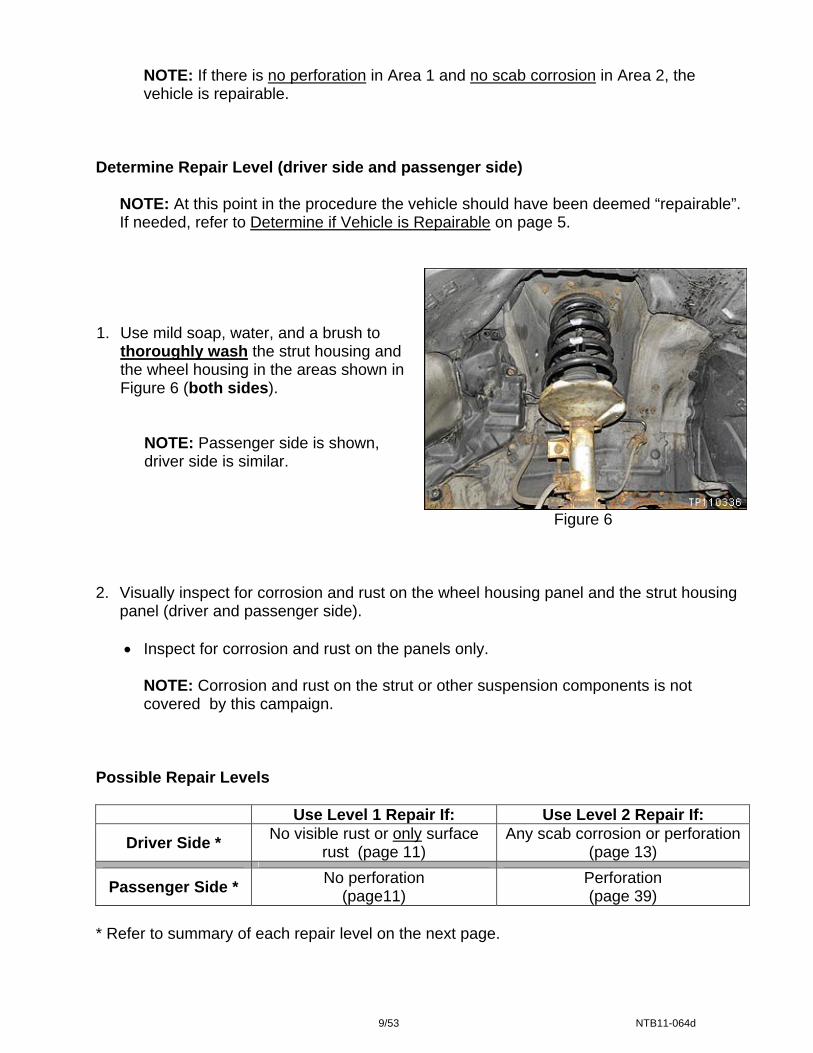
1. Use mild soap, water, and a brush to
thoroughly wash the strut housing and the wheel housing in the areas shown in Figure 6 (both sides).
NOTE: Passenger side is shown, driver side is similar.
Figure 6
2. Visually inspect for corrosion and rust on the wheel housing panel and the strut housing
panel (driver and passenger side).
• Inspect for corrosion and rust on the panels only.
NOTE: Corrosion and rust on the strut or other suspension components is not covered by this campaign.
Possible Repair Levels
Use Level 1 Repair If: Use Level 2 Repair If:
Driver Side * No visible rust or only surface rust (page 11)
Any scab corrosion or perforation(page 13)
Passenger Side * No perforation (page11)
Perforation (page 39)
* Refer to summary of each repair level on the next page.
9/53 NTB11-064d

Summary of Repair Levels Driver Side Level 1 – No visible rust or only surface rust
• Use an abrasive tool to remove surface rust. • Clean wheel housing and strut housing area. Page 11 • Apply self etching primer. • Apply rubberized undercoating.
Level 2 – Any scab corrosion or perforation
• Remove the strut. • Use an abrasive tool to remove loose
corrosion and rust. Page 13 • Apply self etching primer.
• Install the repair bracket. • Patch perforated areas – if needed. • Apply rubberized undercoating.
Passenger Side Level 1 – No perforation
• Use an abrasive tool or scraper to remove rust. • Clean wheel housing and strut housing area. Page 11 • Apply self etching primer. • Apply rubberized undercoating.
Level 2 – Perforation
• Use an abrasive tool to remove loose corrosion and rust.
(Only if needed, remove the strut to access perforated area.) Page 39 • Apply self etching primer. • Patch perforated areas. • Apply rubberized undercoating.
10/53 NTB11-064d

LEVEL 1 REPAIR (driver side and passenger side)
For passenger side - no perforation
For driver side - no visible rust or only surface rust
WARNING: Perform repairs in a well ventilated area.
NOTE:
• Plastic covers (fender protectors) in the wheel house area do not need to be removed.
• Photos in this section are of the passenger side, driver side is similar.
• For 4WD vehicles: If the drive shaft boot is ripped, it should be covered to prevent debris from entering the drive shaft joint.
Figure 7
Figure 8
1. Use a wire brush to remove loose rust in
the area shown with dashed line.
2. Clean dust, dirt, or other debris from the
wheel housing and strut housing area.
3. Cover the strut so it is protected from overspray.
4. Completely and liberally coat the strut
housing and wheel house area with self etching primer.
• Use Dupont Etch Primer (P/N A-4119S™) or equivalent.
• Follow all product instructions.
• Coat all of the exposed metal areas on the strut housing and wheel house panels.
• A second coat may be needed for heavy rust spots.
• Let each coat dry for 5 minutes.
NOTE: Refer to the Parts Information for additional product details.
11/53 NTB11-064d
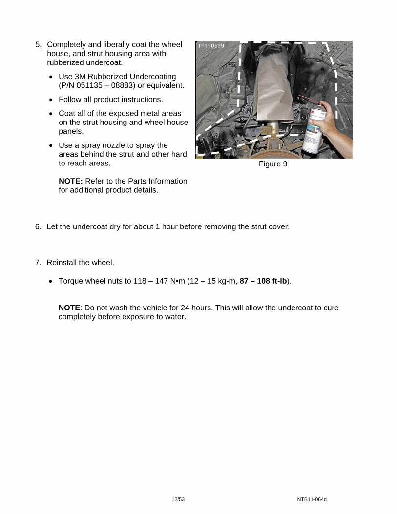
Figure 9
5. Completely and liberally coat the wheel house, and strut housing area with rubberized undercoat.
• Use 3M Rubberized Undercoating (P/N 051135 – 08883) or equivalent.
• Follow all product instructions.
• Coat all of the exposed metal areas on the strut housing and wheel house panels.
• Use a spray nozzle to spray the areas behind the strut and other hard to reach areas.
NOTE: Refer to the Parts Information for additional product details.
6. Let the undercoat dry for about 1 hour before removing the strut cover. 7. Reinstall the wheel.
• Torque wheel nuts to 118 – 147 N•m (12 – 15 kg-m, 87 – 108 ft-lb).
NOTE: Do not wash the vehicle for 24 hours. This will allow the undercoat to cure completely before exposure to water.
12/53 NTB11-064d
DRIVER SIDE – LEVEL 2 REPAIR
Front Strut Removal
NOTE:
• Use care during strut removal to prevent stress on electrical, hydraulic, and mechanical components.
• If needed; spray the strut mounting bolts/nuts with Nissan Rust Penetrant (P/N 999MP-A3020P) or equivalent.
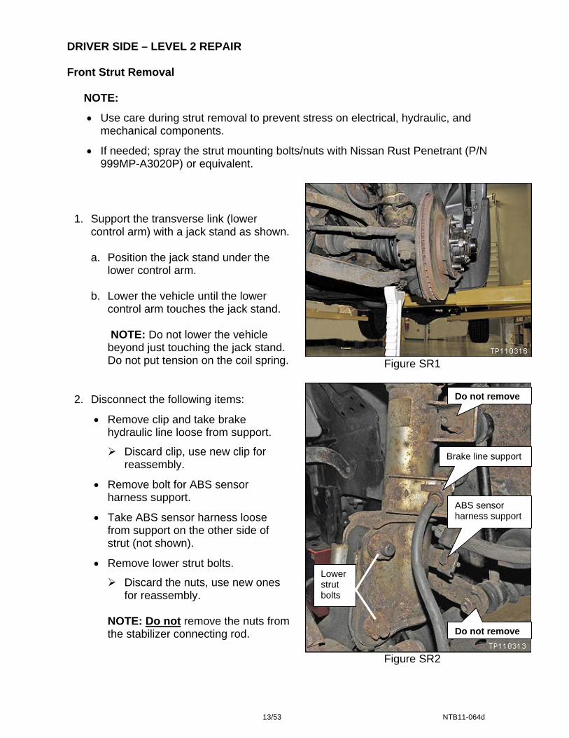
Figure SR1
1. Support the transverse link (lower
control arm) with a jack stand as shown. a. Position the jack stand under the
lower control arm. b. Lower the vehicle until the lower
control arm touches the jack stand.
NOTE: Do not lower the vehicle beyond just touching the jack stand. Do not put tension on the coil spring.
Brake line support
ABS sensor harness support
Do not remove
Lower strut bolts
Do not remove
2. Disconnect the following items:
• Remove clip and take brake hydraulic line loose from support.
Discard clip, use new clip for reassembly.
• Remove bolt for ABS sensor harness support.
• Take ABS sensor harness loose from support on the other side of strut (not shown).
• Remove lower strut bolts.
Discard the nuts, use new ones for reassembly.
NOTE: Do not remove the nuts from the stabilizer connecting rod.
Figure SR2
13/53 NTB11-064d

3. Carefully separate the knuckle from the strut.
NOTE: Do not let the knuckle fall away from the strut. This will cause the weight of the knuckle assemble to pull on the brake line and the driveshaft boot (if equipped).
4. Use an elastic strap or other suitable
tool to secure the knuckle to the stabilizer bar as shown.
NOTE: Make sure the knuckle assembly is secure. Its weight must be supported during the entire repair process.
Elastic strap
Figure SR3
Figure SR4
Figure SR5
5. Remove the 2 bolts for the ABS
sensor connector cover.
Bolts
ABS sensor connector
6. Disconnect the ABS sensor
connector.
• ABS sensor connector is on the back side of the cover.
ABS sensor connector cover
14/53 NTB11-064d

7.
8.
9.
ABS sensor harness
Figure SR6
10
11
Pull the ABS sensor harness from behind the strut.
Let the ABS sensor harness hang out of the way as shown.
Raise the vehicle enough so the lower control arm is not touching the jack stand.
Figure SR7
Nuts
. Remove the 3 upper strut mounting nuts.
• Discard the nuts, use new ones for reassembly.
Figure SR8
. Maneuver the strut so it is hanging upside down as shown.
NOTE: The weight of strut is supported by the stabilizer connecting rod.
15/53 NTB11-064d
Repair Bracket Installation for Driver Side Strut Housing (Driver side level 2 repair continued)
WARNING: Perform repairs in a well ventilated area.
NOTE:
• For 4WD vehicles: If the driveshaft boot is ripped, it should be covered to prevent debris from entering the driveshaft joint.
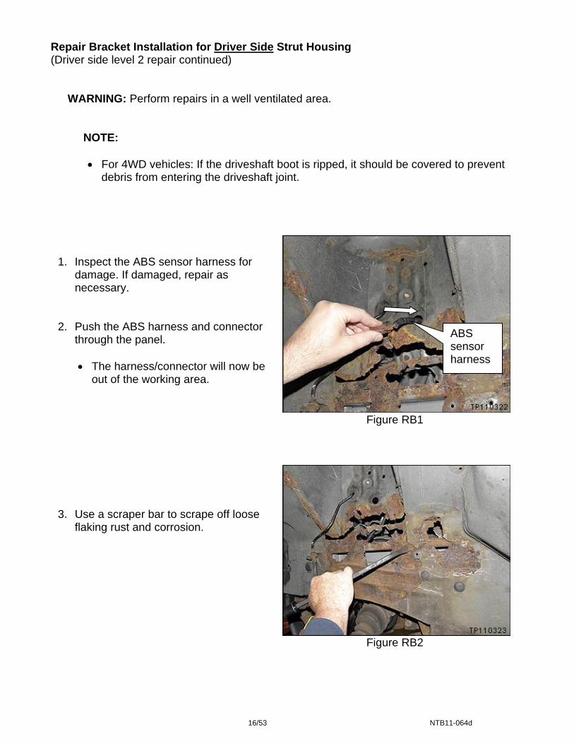
Figure RB1
1. Inspect the ABS sensor harness for
damage. If damaged, repair as necessary.
2. Push the ABS harness and connector
through the panel.
• The harness/connector will now be out of the working area.
ABS sensor harness
3. Use a scraper bar to scrape off loose
flaking rust and corrosion.
Figure RB2
16/53 NTB11-064d
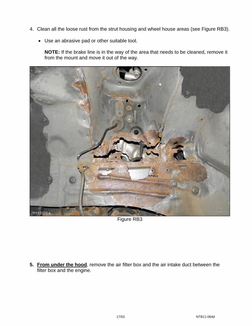
4. Clean all the loose rust from the strut housing and wheel house areas (see Figure RB3).
• Use an abrasive pad or other suitable tool.
NOTE: If the brake line is in the way of the area that needs to be cleaned, remove it from the mount and move it out of the way.
Figure RB3
5. From under the hood, remove the air filter box and the air intake duct between the
filter box and the engine.
17/53 NTB11-064d
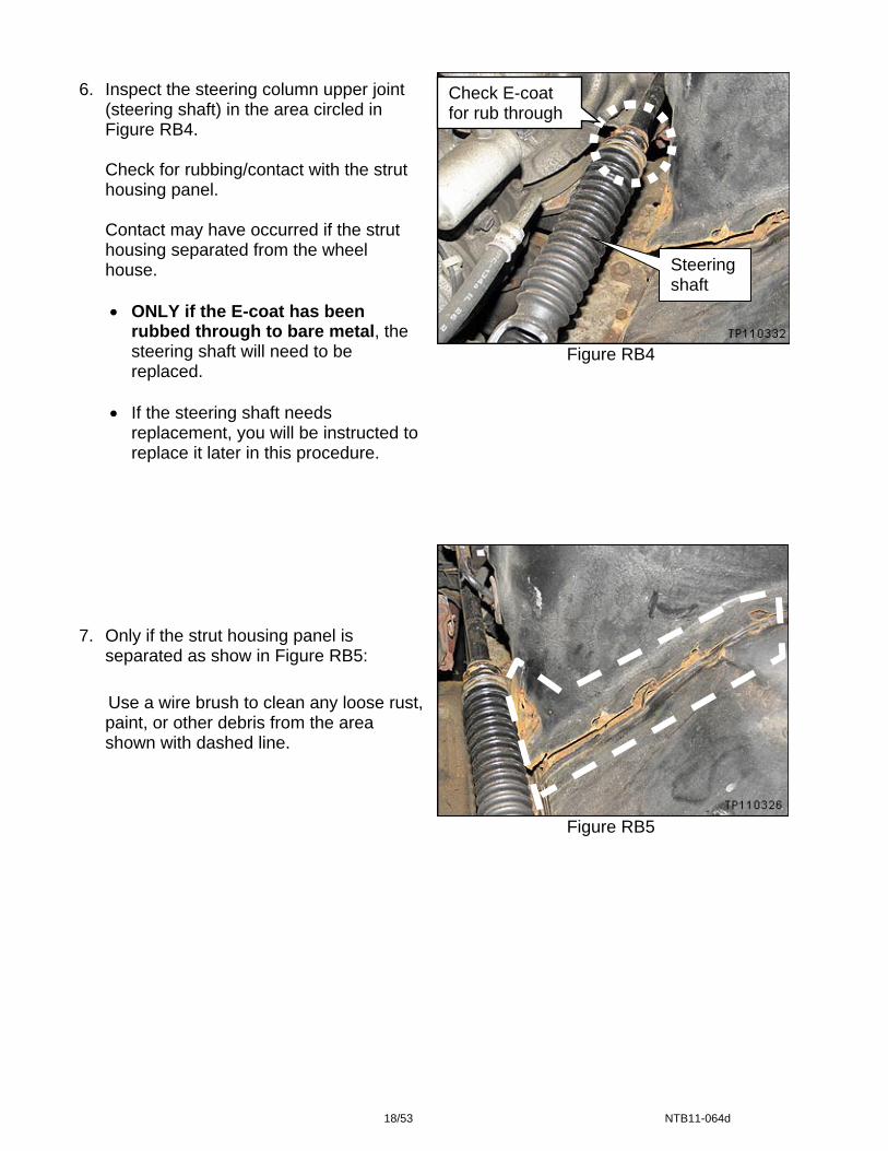
Figure RB4
Figure RB5
6. Inspect the steering column upper joint (steering shaft) in the area circled in Figure RB4.
Check for rubbing/contact with the strut housing panel.
Contact may have occurred if the strut housing separated from the wheel house.
• ONLY if the E-coat has been
rubbed through to bare metal, the steering shaft will need to be replaced.
• If the steering shaft needs replacement, you will be instructed to replace it later in this procedure.
Steering shaft
Check E-coat for rub through
7. Only if the strut housing panel is
separated as show in Figure RB5: Use a wire brush to clean any loose rust,
paint, or other debris from the area shown with dashed line.
18/53 NTB11-064d
8. Use low pressure compressed air to blow off dust and debris:
• From the under hood side of the strut housing panel and the surrounding area, and
• From the wheel house area. 9. Use isopropyl alcohol to clean/wipe down the area:
• If the strut housing panel was separated, clean/wipe down the under hood side of the strut housing panel and the surrounding area.
• Clean/wipe down the wheel house area.
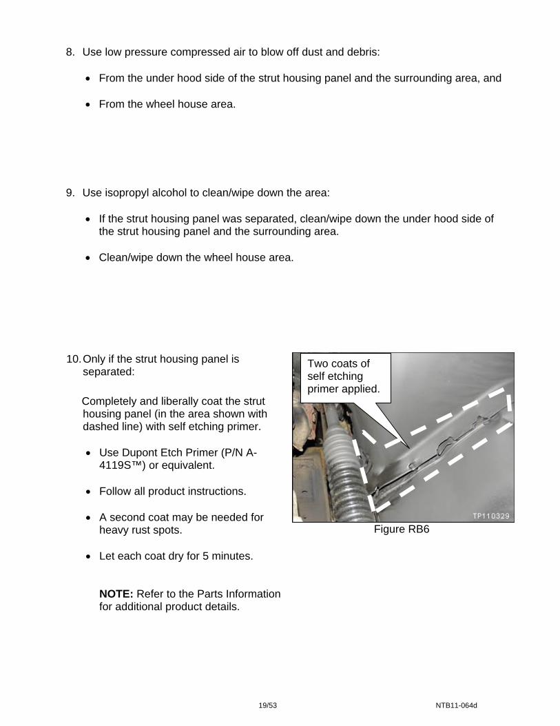
10. Only if the strut housing panel is
separated: Completely and liberally coat the strut
housing panel (in the area shown with dashed line) with self etching primer.
• Use Dupont Etch Primer (P/N A-4119S™) or equivalent.
• Follow all product instructions.
• A second coat may be needed for heavy rust spots.
• Let each coat dry for 5 minutes.
NOTE: Refer to the Parts Information for additional product details.
Two coats of self etching primer applied.
Figure RB6
19/53 NTB11-064d
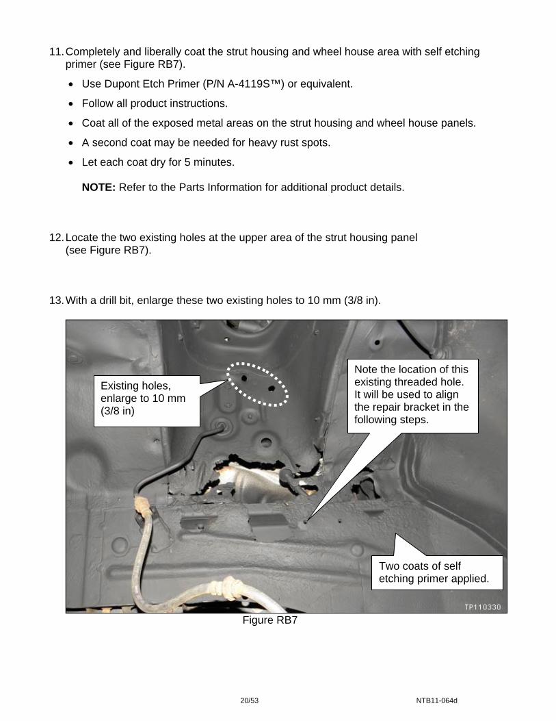
11. Completely and liberally coat the strut housing and wheel house area with self etching
primer (see Figure RB7).
• Use Dupont Etch Primer (P/N A-4119S™) or equivalent.
• Follow all product instructions.
• Coat all of the exposed metal areas on the strut housing and wheel house panels.
• A second coat may be needed for heavy rust spots.
• Let each coat dry for 5 minutes.
NOTE: Refer to the Parts Information for additional product details. 12. Locate the two existing holes at the upper area of the strut housing panel
(see Figure RB7). 13. With a drill bit, enlarge these two existing holes to 10 mm (3/8 in).
Figure RB7
Note the location of this existing threaded hole. It will be used to align the repair bracket in the following steps.
Two coats of self etching primer applied.
Existing holes, enlarge to 10 mm (3/8 in)
20/53 NTB11-064d
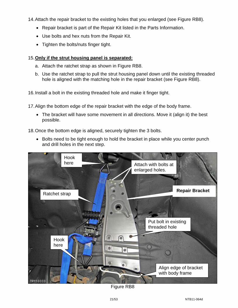
14. Attach the repair bracket to the existing holes that you enlarged (see Figure RB8).
• Repair bracket is part of the Repair Kit listed in the Parts Information.
• Use bolts and hex nuts from the Repair Kit.
• Tighten the bolts/nuts finger tight.
15. Only if the strut housing panel is separated:
a. Attach the ratchet strap as shown in Figure RB8.
b. Use the ratchet strap to pull the strut housing panel down until the existing threaded hole is aligned with the matching hole in the repair bracket (see Figure RB8).
16. Install a bolt in the existing threaded hole and make it finger tight.
17. Align the bottom edge of the repair bracket with the edge of the body frame.
• The bracket will have some movement in all directions. Move it (align it) the best possible.
18. Once the bottom edge is aligned, securely tighten the 3 bolts.
• Bolts need to be tight enough to hold the bracket in place while you center punch and drill holes in the next step.
Hook here
Ratchet strap
Hook here
Figure RB
21/53
Attach with bolts at enlarged holes.
Repair Bracket
Put bolt in existing threaded hole
Align edge of bracket with body frame
8
NTB11-064d
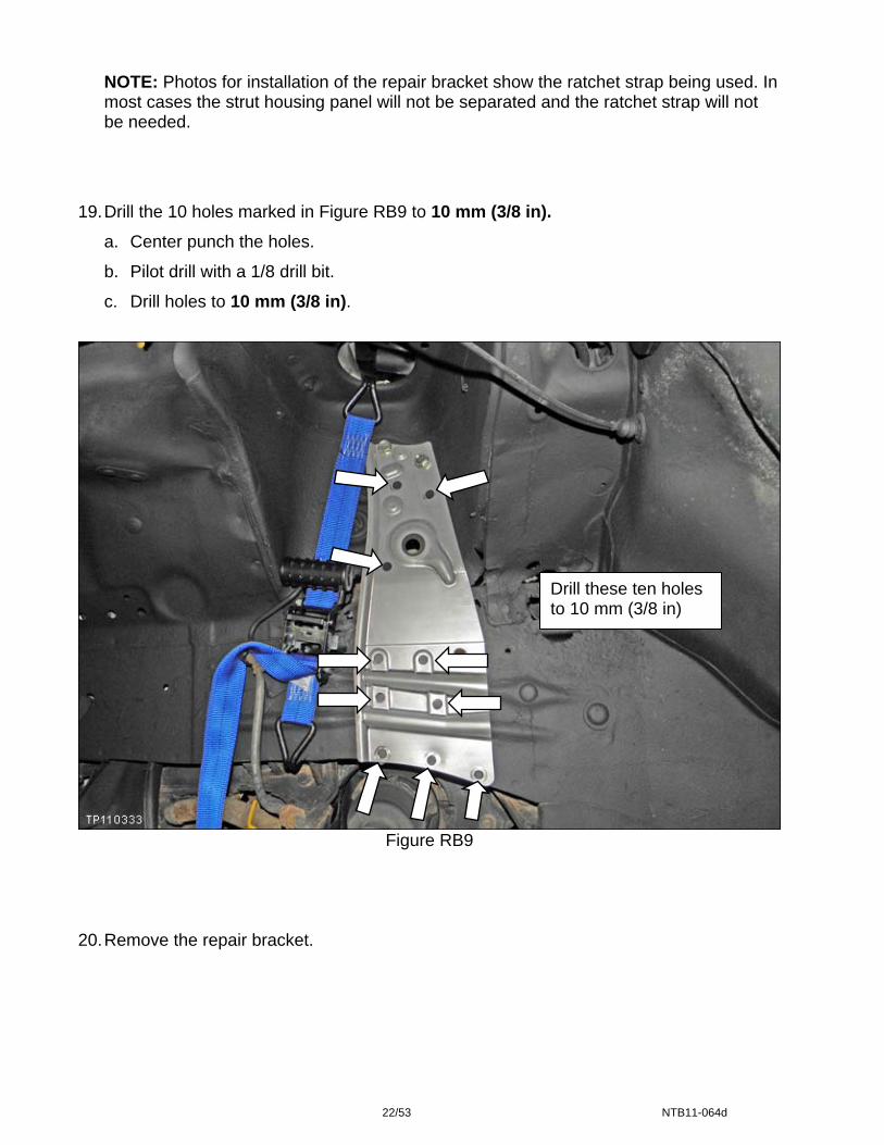
NOTE: Photos for installation of the repair bracket show the ratchet strap being used. In most cases the strut housing panel will not be separated and the ratchet strap will not be needed.
19. Drill the 10 holes marked in Figure RB9 to 10 mm (3/8 in).
a. Center punch the holes.
b. Pilot drill with a 1/8 drill bit.
c. Drill holes to 10 mm (3/8 in).
Figure RB9 20. Remove the repair bracket.
22/53
Drill these ten holes to 10 mm (3/8 in)
NTB11-064d

21. For the 4 holes that will have Rivet Nuts installed, drill final hole size to 13.1 mm (33/64 in). See Figure RB10.
NOTE: Each dealer was shipped, at no charge, one 33/64 drill bit (J-50878).
22. Install Rivet Nuts in the 13.1 mm (33/64 in) holes (see Figure RB10).
• Refer to Rivet Nut Installation Instructions on the next page.
CAUTION: DO NOT use power tools or impact tools with the Rivet Gun – use hand tools only.
IMPORTANT:
• Lower holes - Required: Rivet Nuts are required in the lower holes (indicated with dashed line in Figure RB10).
If the metal in the area of the lower holes will not support the Rivet Nuts, then the vehicle is “not repairable”: Retain the vehicle at the dealer, supply the customer with a rental car, and Fax a completed Non-Repairable Report to Morley (see page 53).
NOTE: Upper holes – not required: If the metal in the area of the upper holes will not support Rivet Nuts, continue with the repair. Rivet Nuts are preferred but not required in the upper holes.
Lower holes for Rivet Nuts
Drill these holes to final size of 13.1 mm (33/64 in)
Upper holes for Rivet Nuts - see NOTE above
Figure RB10
23/53 NTB11-064d

Rivet Nut Installation Instructions
CAUTION: DO NOT use power tools or impact tools with the Rivet Gun – use hand tools only.
Remove collapsed Rivet Nut
Figure RB11
NOTE: First time use:
• The rivet gun may be shipped with a collapsed Rivet Nut installed on the mandrel.
• Remove the collapsed Rivet Nut and
discard.
Figure RB12
Figure RB13
IMPORTANT STEP: A. Turn the hex nut on the rivet gun
counterclockwise until it stops (turn to “Set” position).
NOTE: See label on tool.
Label
Rivet Nut
B. Screw a new Rivet Nut onto the mandrel.
24/53 NTB11-064d
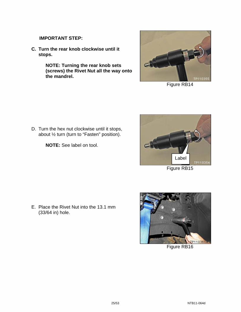
Figure RB14
Figure RB15
Figure RB16
IMPORTANT STEP: C. Turn the rear knob clockwise until it
stops.
NOTE: Turning the rear knob sets (screws) the Rivet Nut all the way onto the mandrel.
D. Turn the hex nut clockwise until it stops,
about ½ turn (turn to “Fasten” position).
NOTE: See label on tool.
Label
E. Place the Rivet Nut into the 13.1 mm
(33/64 in) hole.
25/53 NTB11-064d

CAUTION: DO NOT use power tools or impact tools with the Rivet Gun – use hand tools only.
F. Hold the tool at a right angle to the hole. G. Use a 19 mm wrench to turn the hex nut a
maximum of clockwise 2 ½ to 2 ¾ turns.
• Use the mark (white dot) on top of the hex nut to keep track of the number of turns.
Figure RB17
H. Turn the hex nut about ½ turn counterclockwise
to release the mandrel tension.
Figure RB18
Figure RB19
I. Turn the rear knob counterclockwise to remove
(unscrew) the mandrel from the Rivet Nut.
26/53 NTB11-064d
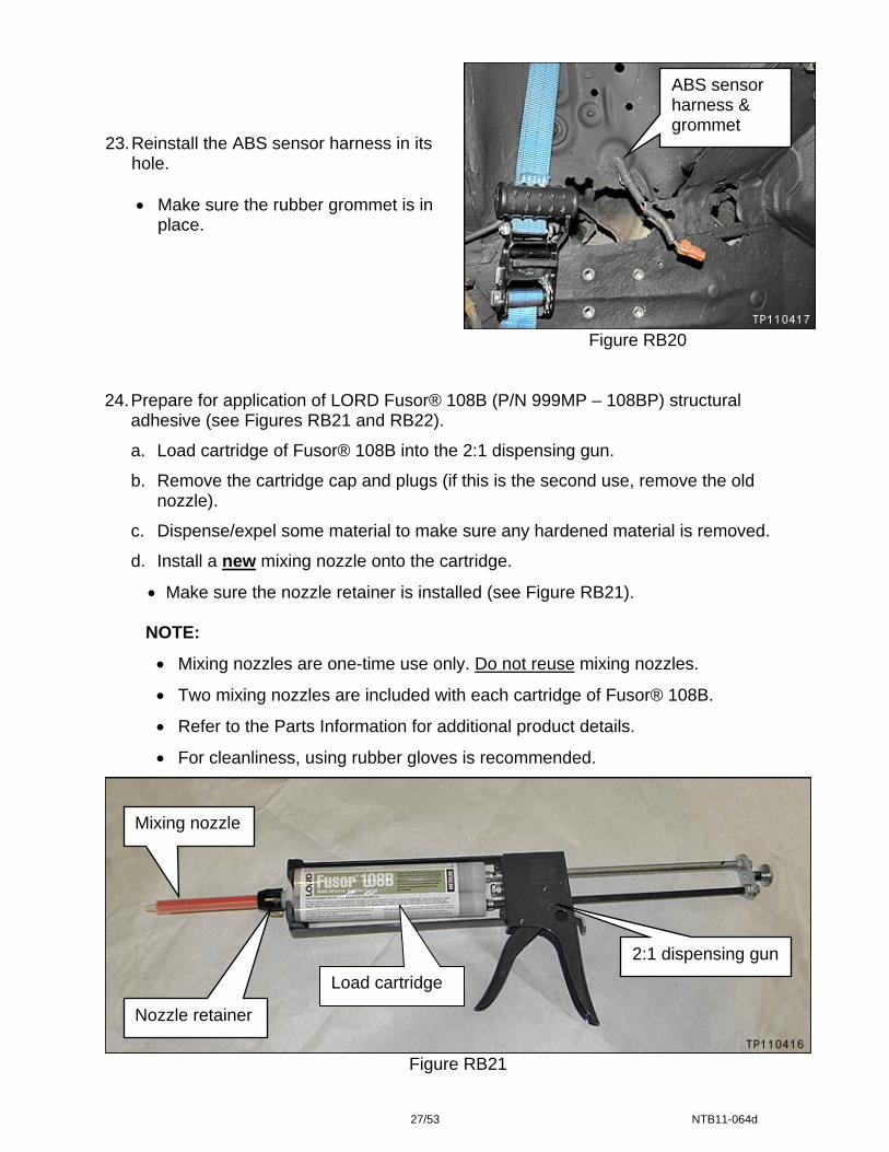
ABS sensor harness & grommet
23. Reinstall the ABS sensor harness in its
hole.
• Make sure the rubber grommet is in place.
Figure RB20
24. Prepare for application of LORD Fusor® 108B (P/N 999MP – 108BP) structural
adhesive (see Figures RB21 and RB22).
a. Load cartridge of Fusor® 108B into the 2:1 dispensing gun.
b. Remove the cartridge cap and plugs (if this is the second use, remove the old nozzle).
c. Dispense/expel some material to make sure any hardened material is removed.
d. Install a new mixing nozzle onto the cartridge.
• Make sure the nozzle retainer is installed (see Figure RB21).
NOTE:
• Mixing nozzles are one-time use only. Do not reuse mixing nozzles.
• Two mixing nozzles are included with each cartridge of Fusor® 108B.
• Refer to the Parts Information for additional product details.
• For cleanliness, using rubber gloves is recommended.
Mixing nozzle
2:1 dispensing gun Load cartridge
Nozzle retainer
Figure RB21
27/53 NTB11-064d

RB22
Figure RB23
25. Liberally apply Fusor® 108B to the
back side of the repair bracket as shown.
• The adhesive bead should be about ¼ diameter in all the areas shown.
NOTE: Filling the two channels with 3 beads will ensure good adhesion in the channel area.
c. Dispense 2 beads of Fusor® 108B
onto a paper that will be discarded.
• Each bead should be about ¼ inch diameter and about 6 inches long (length of the nozzle).
NOTE: Performing this action will ensure the dispenser plungers have leveled, air bubbles have been expelled, and adhesive is mixed correctly.
NOTE:
• Each cartridge of Fusor® 108B has enough material to install two repair
• Leave the nozzle attached to the cartridge between applications. The nozkeep the cartridge sealed until the next use.
28/53 NTB
Layer 3 beads in these two channels
brackets.
zle will
11-064d

26. Bolt the repair bracket into place.
• Make sure the ABS harness is pulled through its hole (see Figure RB24).
• Use the correct nuts (see Figure RB24).
• Do not use air tools to tighten the bolts.
• Torque all bolt/nuts to 50 N•m (5.1 kg-m, 37 ft-lb).
27. Make sure adhesive is cleaned from the existing threaded hole (see Figure RB24).
NOTE: This hole is used to mount the ABS sensor connector cover. 28. If the ratchet strap was used, carefully remove it. 29. Clean excess adhesive from around the edges of the repair bracket.
Figure RB24
ABS harness pulled through
Clean excess adhesive from bracket edges
Existing threaded hole. Clean any adhesive from this hole
NOTE: See additional repair bracket bolt installation information on the next page.
29/53 NTB11-064d

Additional Bolt Installation Information
Bolts that are preferred but not required (see Figure RB25):
• If these bolts do not have enough metal to support them (make them tight), use Lord Fusor® 108B to glue the bolts in the holes. Do not leave open holes. These bolts are preferred for bracket support, but not required.
Bolts with Rivet Nuts that Must accept the torque (see Figure RB25):
• These bolts are required and must accept the torque value of 50 N•m (5.1 kg-m, 37 ft-lb).
• If these bolts will not accept the specified torque value, the vehicle is not repairable:
a. Retain the vehicle at the dealer.
b. Supply the customer with a rental car.
c. Fax a completed Non-Repairable Report to Morley (see page 53).
Must accept torque
Preferred but not required See information above
Figure RB25
30/53 NTB11-064d

30. Inspect the metal brake line for damage. If there is damage, replace the line.
• Inspect the line in the wheel house area (see Figure RB26).
Metal brake line in wheel house
Figure RB26
• Inspect the line under the hood (see Figure RB27).
• Scratches or nicks of the E-coat are not considered damage that requires brake line replacement.
• Refer to the appropriate Service
Manual for brake line replacement information.
Metal brake line under hood
Figure RB27
31. If the strut housing was separated, inspect the brake master cylinder for damage.
Contact with the strut housing may have occurred if the strut housing separated from the wheel house.
• If there is damage, replace the
master cylinder.
• Refer the appropriate Service Manual for brake master cylinder replacement information.
Brake master cylinder
Figure RB28
31/53 NTB11-064d

Patching Perforated Areas (Driver side level 2 repair continued)
NOTE: The Photo in Figure RB29 is an example of possible perforation. The vehicle you are working on may have perforation in additional areas, areas different than these, or may not have any perforation.
If the vehicle you are working on does not have perforation, skip to step 35. 32. Cut fiberglass cloth to cover perforated areas (see example in Figure RB29).
• Cut cloth to cover at least 1 inch beyond the perforation on all sides, except when the perforation is next to the repair bracket.
• Where perforation is next to the repair bracket, cut cloth to fit along the edge of the repair bracket.
• If there is more then one perforation, cut fiberglass cloth for each perforated area.
• Use 3M™ Bondo Fiberglass Repair Kit (P/N 422) or equivalent.
• Use protective gloves (such as rubber gloves or disposable gloves) while working with fiberglass and resin.
• Do not install fiberglass patch on or over the repair bracket.
Cut fiberglass cloth to cover at least 1 inch beyond the perforation
Cut fiberglass cloth to cover at least 1 inch beyond the perforation
Do not cover this hole. It is used for the ABS harness bracket.
Example of perforation
Figure RB29
32/53 NTB11-064d
33. Apply fiberglass patch to perforated areas.
• No additional surface preparation is needed.
Apply patch over the self etching primer.
Cleaning/grinding to bare metal is not needed. • Use protective gloves (such as rubber gloves or disposable gloves) while working
with fiberglass and resin. • Follow all warnings and cautions for the fiberglass product being used.
• Follow the product instructions for applying the fiberglass patch.
WARNING: Perform repairs in a well ventilated area.
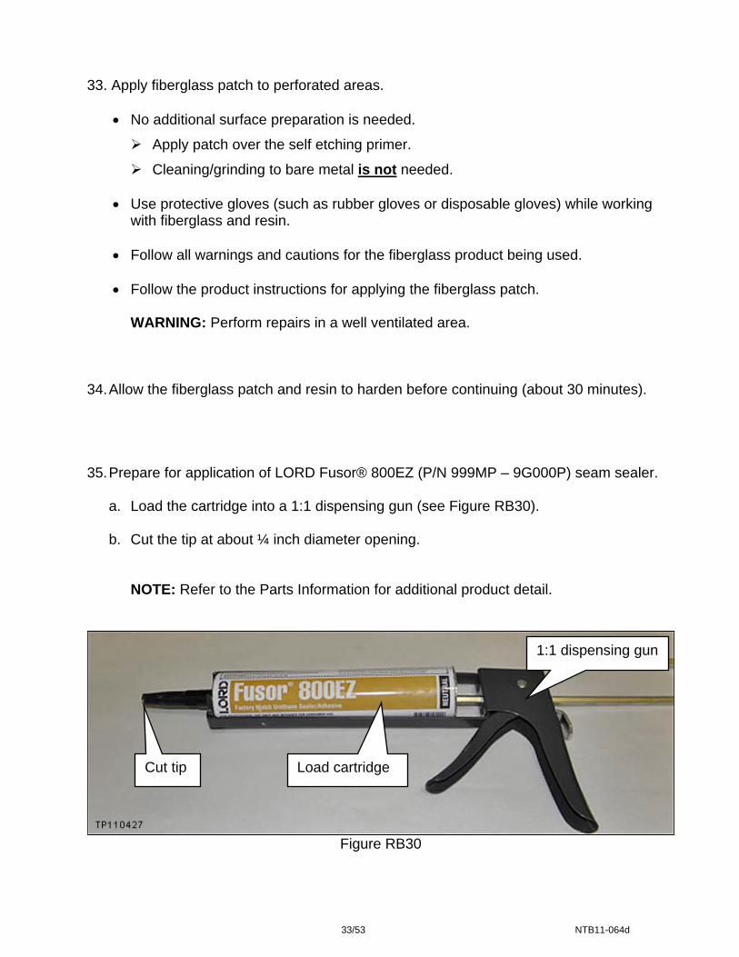
34. Allow the fiberglass patch and resin to harden before continuing (about 30 minutes). 35. Prepare for application of LORD Fusor® 800EZ (P/N 999MP – 9G000P) seam sealer.
a. Load the cartridge into a 1:1 dispensing gun (see Figure RB30). b. Cut the tip at about ¼ inch diameter opening.
NOTE: Refer to the Parts Information for additional product detail.
1:1 dispensing gun
Cut tip Load cartridge
Figure RB30
33/53 NTB11-064d

36. Apply Fusor® 800EZ (seam sealer) as shown in Figure RB31.
• Apply around the outer edges of the repair bracket. Make sure all gaps are filled. • Apply along the seams between the strut housing panel and the wheel house. • Use a brush or other suitable tool to smooth the sealer for good seam coverage. • Allow seam sealer to dry for 10-15 minutes.
37. Apply Butyl Sealer (P/N B6553 – 89915) around the opening for the ABS sensor
harness (see Figure RB31).
Butyl Sealer around the hole for ABS sensor harness
Seam between strut housing panel and wheel house
Outer edge of repair bracket
Figure RB31
38. Only if strut housing panel is separated:
Apply Fusor® 800EZ (seam sealer) as shown in Figure RB32.
• Apply along the front seam between the strut housing panel and the wheel house.
• Use a brush or other suitable tool to smooth the sealer for good seam coverage.
• Allow seam sealer to dry for 10-15 minutes.
Figure RB32
34/53 NTB11-064d
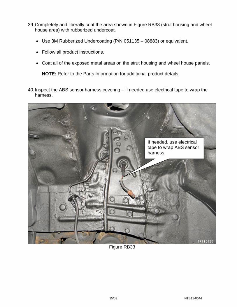
39. Completely and liberally coat the area shown in Figure RB33 (strut housing and wheel
house area) with rubberized undercoat.
• Use 3M Rubberized Undercoating (P/N 051135 – 08883) or equivalent.
• Follow all product instructions. • Coat all of the exposed metal areas on the strut housing and wheel house panels.
NOTE: Refer to the Parts Information for additional product details. 40. Inspect the ABS sensor harness covering – if needed use electrical tape to wrap the
harness.
If needed, use electrical tape to wrap ABS sensor harness.
Figure RB33
35/53 NTB11-064d
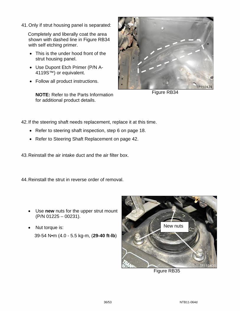
Figure RB34
42. If the steering shaft needs replacement, replace it at this time.
• Refer to steering shaft inspection, step 6 on page 18.
• Refer to Steering Shaft Replacement on page 42. 43. Reinstall the air intake duct and the air filter box.
44. Reinstall the strut in reverse order of removal.
Figure RB35
41. Only if strut housing panel is separated: Completely and liberally coat the area
shown with dashed line in Figure RB34 with self etching primer.
• This is the under hood front of the strut housing panel.
• Use Dupont Etch Primer (P/N A-4119S™) or equivalent.
• Follow all product instructions.
NOTE: Refer to the Parts Information for additional product details.
New nuts
• Use new nuts for the upper strut mount
(P/N 01225 – 00231). • Nut torque is:
39-54 N•m (4.0 - 5.5 kg-m, (29-40 ft-lb)
36/53 NTB11-064d
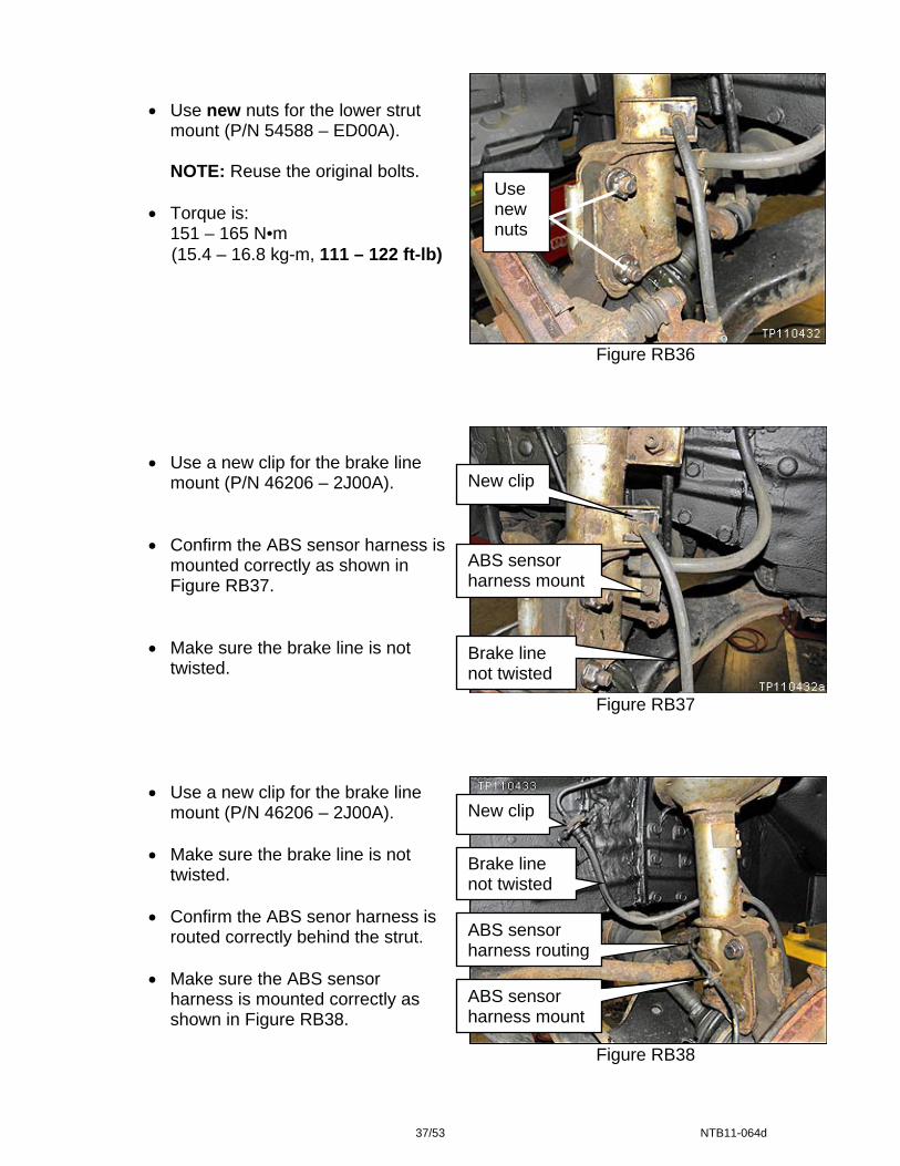
Figure RB36
Figure RB37
• Use new nuts for the lower strut
mount (P/N 54588 – ED00A).
NOTE: Reuse the original bolts.
• Torque is: 151 – 165 N•m
(15.4 – 16.8 kg-m, 111 – 122 ft-lb)
Use new nuts
ABS sensor harness mount
Brake line not twisted
New clip
• Use a new clip for the brake line
mount (P/N 46206 – 2J00A).
• Confirm the ABS sensor harness is mounted correctly as shown in Figure RB37.
• Make sure the brake line is not twisted.
Figure RB38
ABS sensor harness routing
ABS sensor harness mount
Brake line not twisted
New clip • Use a new clip for the brake line
mount (P/N 46206 – 2J00A).
• Make sure the brake line is not twisted.
• Confirm the ABS senor harness is
routed correctly behind the strut. • Make sure the ABS sensor
harness is mounted correctly as shown in Figure RB38.
37/53 NTB11-064d
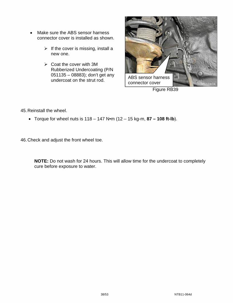
• Make sure the ABS sensor harness connector cover is installed as shown.
If the cover is missing, install a
new one.
Coat the cover with 3M Rubberized Undercoating (P/N 051135 – 08883); don’t get any undercoat on the strut rod.
Figure RB39
ABS sensor harness connector cover
45. Reinstall the wheel.
• Torque for wheel nuts is 118 – 147 N•m (12 – 15 kg-m, 87 – 108 ft-lb). 46. Check and adjust the front wheel toe.
NOTE: Do not wash for 24 hours. This will allow time for the undercoat to completely cure before exposure to water.
38/53 NTB11-064d

PASSENGER SIDE – LEVEL 2 REPAIR
WARNING: Perform repairs in a well ventilated area.
Figure PS1
NOTE:
• This repair is only used if there is metal perforation on the passenger side in the area show in Figure PS1.
• If there is no perforation, go to Level 1 repair on page 11.
• For 4WD vehicles: If the drive shaft boot is ripped, it should be covered to prevent debris from entering the drive shaft joint.
1. Clean all loose rust from the perforated area and other areas in the wheel house, and
strut housing.
• Use an abrasive pad or other suitable tool.
• Only if necessary to access the perforated area, remove the right front strut. Refer to Strut Removal on page 13.
2. Use low pressure compressed air to blow off dust and debris from the cleaned area. 3. Use isopropyl alcohol to clean/wipe down the area.
39/53 NTB11-064d

4. Completely and liberally coat the strut housing and wheel house area with self etching primer (see Figure PS2).
• Use Dupont Etch Primer (P/N A-4119S™) or equivalent.
• Follow all product instructions.
• Coat all of the exposed metal areas on the strut housing and wheel house panels.
• A second coat may be needed for heavy rust spots.
• Let each coat dry for 5 minutes.
Figure PS2
NOTE: • If the strut has not been removed,
cover the strut so it is protected from overspray.
5. Cut a piece of fiberglass cloth to cover at least 1 inch beyond the perforation on all
sides.
• If there is more then one perforation, cut fiberglass cloth for each perforated area.
• Use 3M™ Bondo Fiberglass Repair Kit (P/N 422) or equivalent.
• Use protective gloves (such as rubber gloves or disposable gloves) while working with fiberglass and resin.
6. Apply fiberglass patch to the perforated area.
• No additional surface preparation is needed.
Apply patch over the self etching primer.
Cleaning/grinding to bare metal is not needed.
• Use protective gloves (such as rubber gloves or disposable gloves) while working with fiberglass and resin.
• Follow all warnings and cautions for the fiberglass product being used.
• Follow the product instructions for applying the fiberglass patch.
40/53 NTB11-064d
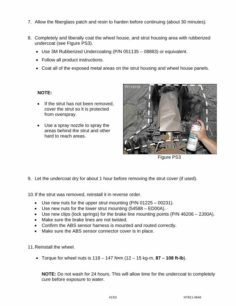
7. Allow the fiberglass patch and resin to harden before continuing (about 30 minutes). 8. Completely and liberally coat the wheel house, and strut housing area with rubberized
undercoat (see Figure PS3).
• Use 3M Rubberized Undercoating (P/N 051135 – 08883) or equivalent.
• Follow all product instructions.
• Coat all of the exposed metal areas on the strut housing and wheel house panels.
9. L 10.
11. R
NOTE: • If the strut has not been removed,
cover the strut so it is protected from overspray.
• Use a spray nozzle to spray the areas behind the strut and other hard to reach areas.
Figure PS3et the undercoat dry for about 1 hour before removing the strut cover (if used).
If the strut was removed, reinstall it in reverse order.
• Use new nuts for the upper strut mounting (P/N 01225 – 00231). • Use new nuts for the lower strut mounting (54588 – ED00A). • Use new clips (lock springs) for the brake line mounting points (P/N 46206 – 2J00A). • Make sure the brake lines are not twisted. • Confirm the ABS sensor harness is mounted and routed correctly. • Make sure the ABS sensor connector cover is in place.
einstall the wheel.
• Torque for wheel nuts is 118 – 147 N•m (12 – 15 kg-m, 87 – 108 ft-lb).
NOTE: Do not wash for 24 hours. This will allow time for the undercoat to completely cure before exposure to water.
41/53 NTB11-064d
STEERING SHAFT REPLACEMENT
NOTE: Replace the steering column upper joint (steering shaft) only if needed. Refer to steering shaft inspection, step 6 on page 18.
1. Make sure the front wheels are positioned straight ahead.
Clamp bolts
Steering shaft
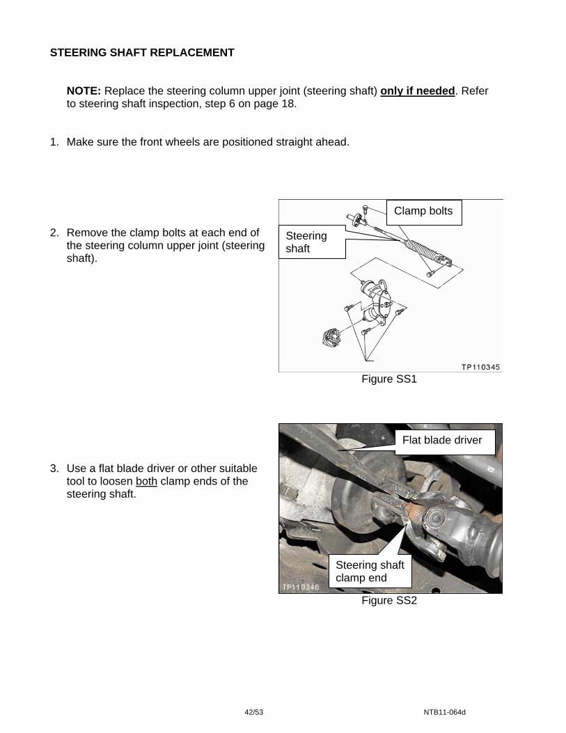
2. Remove the clamp bolts at each end of
the steering column upper joint (steering shaft).
Figure SS1
Figure SS2
3. Use a flat blade driver or other suitable
tool to loosen both clamp ends of the steering shaft.
Flat blade driver
Steering shaft clamp end
42/53 NTB11-064d

4. Loosen the clamp ends enough so the
steering shaft is loose at both ends.
• Steering shaft will move back and forth a small amount.
Figure SS3
5.
6.
Steering wheel holding tool
Set the steering wheel in the straight ahead position.
Position a steering wheel holding tool as shown.
• This will keep the steering wheel stationary while replacing the steering shaft.
Figure SS4
NOTE: The marks shown in Figure SS5 should be aligned.
• Tab on transfer gear assembly
• Raised area on rubber cover
• Gap on steering shaft clamp
Figure SS543/53 NTB11-064d

Figure SS6
7. Remove the 3 transfer gear assembly
mounting bolts.
Transfer gear assembly
Bolts
8. Push the transfer gear assembly
forward and remove the steering shaft.
Steering shaft
Figure SS7
9. Pull the steering shaft to remove it
from the other end.
Steering shaft
Figure SS8
44/53 NTB11-064d

10. Install the new steering shaft in reverse order.
• The shaft end that goes towards the steering wheel is notched; it will go in only one way.
• Make sure shaft end at the steering gear assembly is aligned correctly (see Figure
SS5 on page 43).
• Torque for steering gear assembly mounting bolts is:
20 – 29 N•m (2.0 – 3.0 kg-m, 14 – 22 ft-lb)
• Torque for steering shaft clamp bolts (both ends) is:
24 – 29 N•m (2.4 – 3.0 kg-m, 17 – 22 ft-lb)
45/53 NTB11-064d
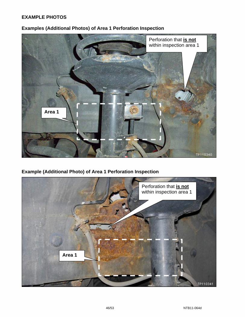
EXAMPLE PHOTOS Examples (Additional Photos) of Area 1 Perforation Inspection
Perforation that is not within inspection area 1
Area 1
Example (Additional Photo) of Area 1 Perforation Inspection
Perforation that is not within inspection area 1
Area 1
46/53 NTB11-064d
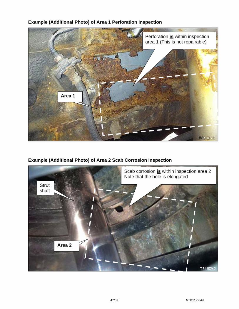
Example (Additional Photo) of Area 1 Perforation Inspection
Perforation is within inspection area 1 (This is not repairable)
Area 1
Example (Additional Photo) of Area 2 Scab Corrosion Inspection
Strut shaft
Scab corrosion is within inspection area 2 Note that the hole is elongated
Area 2
47/53 NTB11-064d

PARTS INFORMATION
Nissan Parts (Local PDC) DESCRIPTION PART # QUANTITY
Repair Kit (Hood Ledge LH Kit A - Includes 1 repair bracket, 12 bolts, 8 nuts and 4 rivet nuts)
F4195 – 0W00C 1, if needed
Joint Assy-STR 14mm shaft (column upper joint – (steering shaft)) 1, if needed
Joint-Assy STR 17mm shaft (column upper joint – (steering shaft))
48070 – 0W00A or
48070--0W001 1, if needed (June 2001-July 2001
production only)
Butyl Sealer (200 cm roll) B6553 – 89915 (1)
1 roll will service approximately 20 vehicles
Clip (spring lock for brake line mounts) 46206 – 2J00A 2, for each strut removed
Nut (for lower strut mount) 54588 – ED00A 2, for each strut removed
Nut (for upper strut mount) 01225 – 00231 3, for each strut removed (1) Do not list this part number on the claim. It is included in Expense Code 101.
Other Products
DESCRIPTION PRODUCT # (2) SOURCE QUANTITY EXPENSE
CODE Self Etching Primer
(DuPont Etch Primer) A-4119S™
(or equivalent) Local DuPont
supplier 1 per vehicle (12 oz can) 100,103
3M Rubberized Undercoating
051135 – 08883 (or equivalent)
Local 3M™ supplier
1 per vehicle (24 oz can) 100
3M Bondo Fiberglass Repair Kit
422 (or equivalent)
Local 3M™ supplier
1 kit will service perforations for 8
strut/wheel housings 102
LORD Fusor® 108B (structural adhesive –
includes 2 mixing nozzles) 999MP – 108BP Nissan
Chemicals
1 cartridge will service 2 repair bracket installations
101, 103
LORD Fusor® 800EZ (seam sealer)
999MP – 9G000P
Nissan Chemicals
1 cartridge for each repair bracket
installation 101
Nissan Rust Penetrant 999MP-A3020P (or equivalent) Nissan chemical Shop Supply -
Disposable mixing container for fiberglass
resin (one time use) N/A Local source 1 container per
level 2 repair. 102
Disposable bush for application of fiberglass
resin (one time use) N/A Local source 1 bush per level 2
repair. 102
Isopropyl Alcohol Local source Shop Supply - (2) Do not list the above product numbers on the claim. Use the corresponding Expense Code.
Local DuPont Supplier: For help finding a local source for the DuPont product listed above or obtaining an MSDS, contact DuPont at 1-800-438-3876. Local 3M™ Supplier: For help finding a local source for the 3M™ products listed above or obtaining an MSDS, contact 3M™ Automotive Aftermarket Division at 1-877-MMM-CARS. Nissan Chemicals: Order this item through the Nissan Maintenance Advantage program: Phone: 877-NIS-NMA1 (877-647-6621), Fax 216.881.7923, Website order via link on dealer portal www.NNAnet.com and click on “Tire Advantage” link or order direct at www.nissantire.com. The MSDS for these chemicals will also be found on this site.
48/53 NTB11-064d

CLAIMS INFORMATION
Submit a Campaign (CM) line claim using the following claims coding:
“CM” I.D.: R1107
Not Repairable Program 1
CAMPAIGN ID DESCRIPTION OP CODE FRT
R1107 Inspect only – vehicle is not repairable R11070 0.3 hrs.
Repairable Program 2
CAMPAIGN ID DESCRIPTION OP CODE FRT EXPENSE CODE
R1107 Level 1 LH and Level 1 RH R11071 1.6 hrs. *100 *Each Expense Code can only be claimed once. Repairable Program 3
CAMPAIGN ID DESCRIPTION OP CODE FRT EXPENSE CODE
R1107 Level 2 LH and Level 1 RH R11072 4.3 hrs. *100,101
Combination Description Op code FRT
Only if needed Replace Steering Column Upper Joint (Steering Shaft) R1107A 0.3 hrs.
Combination Description Op code FRT Expense code
Only if needed Replace Brake Line Front LH Side R1107B 0.3 hrs. *006
Combination Description Op code FRT Expense code
Only if needed Replace Brake Master Cylinder R1107C 0.6 hrs. *006
*Each Expense Code can only be claimed once. Repairable Program 4
CAMPAIGN ID DESCRIPTION OP CODE FRT EXPENSE CODE
R1107 Level 2 LH with Fiberglass Repair and Level 1 RH R11073 4.6 hrs. *100, 101,102
Combination Description Op code FRT
Only if needed Replace Steering Column Upper Joint (Steering Shaft) R1107A 0.3 hrs.
Combination Description Op code FRT Expense code
Only if needed Replace Brake Line Front LH Side R1107B 0.3 hrs. *006
Combination Description Op code FRT Expense code
Only if needed Replace Brake Master Cylinder R1107C 0.6 hrs. *006
*Each Expense Code can only be claimed once.
49/53 NTB11-064d
CLAIMS INFORMATION continued
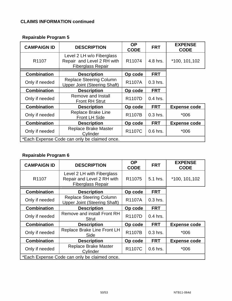
Repairable Program 5
CAMPAIGN ID DESCRIPTION OP CODE FRT EXPENSE
CODE
R1107 Level 2 LH w/o Fiberglass
Repair and Level 2 RH with Fiberglass Repair
R11074 4.8 hrs. *100, 101,102
Combination Description Op code FRT
Only if needed Replace Steering Column Upper Joint (Steering Shaft) R1107A 0.3 hrs.
Combination Description Op code FRT
Only if needed Remove and Install Front RH Strut R1107D 0.4 hrs.
Combination Description Op code FRT Expense code
Only if needed Replace Brake Line Front LH Side R1107B 0.3 hrs. *006
Combination Description Op code FRT Expense code
Only if needed Replace Brake Master Cylinder R1107C 0.6 hrs. *006
*Each Expense Code can only be claimed once.
Repairable Program 6
CAMPAIGN ID DESCRIPTION OP CODE FRT EXPENSE
CODE
R1107 Level 2 LH with Fiberglass Repair and Level 2 RH with
Fiberglass Repair R11075 5.1 hrs. *100, 101,102
Combination Description Op code FRT
Only if needed Replace Steering Column Upper Joint (Steering Shaft) R1107A 0.3 hrs.
Combination Description Op code FRT
Only if needed Remove and install Front RH Strut R1107D 0.4 hrs.
Combination Description Op code FRT Expense code
Only if needed Replace Brake Line Front LH Side R1107B 0.3 hrs. *006
Combination Description Op code FRT Expense code
Only if needed Replace Brake Master Cylinder R1107C 0.6 hrs. *006
*Each Expense Code can only be claimed once.
50/53 NTB11-064d

CLAIMS INFORMATION continued Repairable Program 7
CAMPAIGN ID DESCRIPTION OP CODE FRT EXPENSE
CODE
R1107 Level 1 LH and Level 2 RH with Fiberglass Repair R11076 2.5 hrs. *100,102
Combination Description Op code FRT
Only if needed Remove and Install Front RH Strut R1107D 0.4 hrs.
*Each Expense Code can only be claimed once.
Non repairable Program 8 **
CAMPAIGN ID DESCRIPTION OP CODE FRT EXPENSE
CODE
R1107 Level 2 LH - 1 or both bolts will not torque R11077 3.4 hrs. *103
*Each Expense Code can only be claimed once. **As explained on page 30 and shown in Figure RB25.
EXPENSE CODES
EXPENSE CODE DESCRIPTION MAX AMOUNT 100 Primer and Undercoat $47.88 101 Adhesive, Seam Sealer, and Butyl $68.37
102 Fiberglass Patch, mixing container, and brush $2.70
103 Primer and Adhesive $74.18 006 Brake Fluid $7.98
502 Rental Car
Actual Cost
DO NOT use “Goodwill” for rental car reimbursement
• Each expense code can be claimed only once per repair order. • Corresponding op-code must be claimed with each expense code.
51/53 NTB11-064d

OWNER LETTER Dear Nissan owner:
This second notice is sent to you in accordance with the requirements of the National Traffic and Motor Vehicle Safety Act. Nissan has decided that a defect that relates to motor vehicle safety exists in some 1996-2004 model year Nissan Pathfinder vehicles. Our records indicate that you own or lease the Nissan vehicle identified by the VIN on the cover of this notice. Reason for Recall
Nissan recently discovered that, in certain instances, in states where heavy concentrations of road salt are used in the winter, the front driver’s side strut tower housing can develop corrosion that may cause strut tower housing damage. In certain cases this may allow the strut tower housing to contact the steering column. This would create noise and a noticeable difference in steering effort. If not addressed, this may lead to steering system damage and possibly brake line damage, which could result in a crash.
In the states listed below where there is heavy use of road salt in the winter and corrosion is likely to occur, the dealers will inspect the strut housing and determine the appropriate remedy outlined below.
Connecticut Maine New Hampshire Vermont Delaware Maryland New Jersey West Virginia District of Columbia Massachusetts New York Wisconsin Illinois Michigan Ohio Indiana Minnesota Pennsylvania Iowa Missouri Rhode Island
According to our records, your vehicle is currently registered in one of the states listed above. What Nissan Will Do
In the states shown in the table above, where there is heavy use of road salt in the winter and corrosion is likely to occur, the dealer will inspect the strut housing and perform the following:
• If no corrosion or only minor surface corrosion is present, an anti-corrosion sealant will be applied.
• If moderate corrosion is present, resin patches will be applied in addition to the sealant. • If there is evidence of more significant corrosion, a metal reinforcement plate will be used to
reinforce the strut housing assembly.
The repair will vary based up the remedy required. In rare instances where it is impossible to repair the vehicle, Nissan will provide an appropriate remedy. What You Should Do
Contact your Nissan dealer at your earliest convenience in order to arrange an appointment to have your vehicle inspected. Please bring this notice with you when you keep your service appointment. Instructions have been sent to your Nissan dealer.
If you have paid to have your strut housing sheet metal repaired due to corrosion prior to this campaign, you may be eligible for reimbursement of the related expense. If you have additional questions you may contact the National Consumer Affairs Department, Nissan North America, Inc., P.O. Box 685003, Franklin, TN 37068-5003. The toll free number is 1-800-NISSAN1 (1-800-647-7261). You may also submit a complaint to the Administrator, National Highway Traffic Safety Administration, 1200 New Jersey Avenue, SE., Washington, DC 20590; or call the toll-free Vehicle Safety Hotline at 1-888-327-4236 (TTY: 1-800-424-9153); or go to http://www.safercar.gov.
Federal law requires that any vehicle lessor receiving this recall notice must forward a copy of this notice to the lessee within ten days.
Thank you for your cooperation. We are indeed sorry for any inconvenience this may cause you.
52/53 NTB11-064d

NON REPAIRABLE REPORT
If it is determined that the vehicle is not repairable based on the presence of perforation or scab corrosion, complete the form below and Fax it to Morley (see Fax # below).
• Dealer faxes inspection form to Morley. • Morley contacts the customer within 24 hours to explain the next steps. • Morley schedules and performs an inspection to confirm the dealer’s findings. • Morley will negotiate with the customer. • Morley will schedule a surrender date and provide the dealer with instructions and a
package of documents. • After surrender Morley will arrange the vehicle pickup and scrap.
NISSAN NORTH AMERICA, INC. Pathfinder Strut Corrosion Campaign - Vehicle Not Repairable
CUSTOMER / VEHICLE INFORMATION
LAST NAME: FIRST NAME:
ADDRESS: APT #:
CITY: DEALER NAME:
STATE: DEALER CODE: REGION:
ZIP CODE: CONTACT:
DAY TIME#: TELEPHONE:
CELL #: VIN:
ALT#: MAKE/MODEL: Nissan Pathfinder MILEAGE:
EMAIL: MODEL YEAR: SEC+ #:
NNA Internal Use:
ORIGINATOR CODE = DI
TREAD =VEHICLE CONCERNS / SUSPENSION FRONT STRUT(S) / FINANCIAL ASSISTANCE REQUEST (CAMPAIGN/RECALL)
PLEASE REMEMBER TO DOCUMENT ALL FIELDS COMMENTS:
Morley Fax # Helpdesk #
877-276-2445 877-477-2292
53/53 NTB11-064d