volume a: background and need - brisbane … · volume a: background and need a5 project...
TRANSCRIPT

A5VOLUME A: BACKGROUND AND NEED
Project Description: Runway Construction
NEW PARALLEL RUNWAY DRAFT EIS/MDP FOR PUBLIC COMMENT A5-178

VOLUME A: BACKGROUND AND NEED
Project Description: Runway ConstructionA5
CONTENTS
5.0 Project Description:Runway Construction 181
5.1 Introduction 181
5.1.1 Major Work Phases 181
5.1.2 Project Timeframes 182
5.1.3 Estimated Workforce 182
5.1.4 Hours of Work 183
5.2 Phase 1 – Upgrade of 14/32 Runway 183
5.2.1 Introduction 183
5.2.2 Fencing 183
5.2.3 Construction Compound, Services and Access Roads 184
5.2.4 Topsoil Stripping 184
5.2.5 Ground Treatment 185
5.2.6 Construction of the Seawall 190
5.2.7 Permanent Drainage 190
5.2.8 Relocation of Existing Airport Services 191
5.2.9 Provision for Reclamation Pipeline 192
5.2.10 Water for Construction 192
5.2.11 Asphalt Overlay 192
5.2.12 Concrete Pavements 192
5.2.13 Connections to the Existing Taxiways 193
5.2.14 Flank Reshaping of 14/32 Runway193
5.2.15 Aerodrome Ground Lighting (AGL) 194
5.2.16 Disestablish Site 194
5.2.17 Commission Upgraded 14/32 Runway 194
5.3 Phase 2 – Clearing and Site Preparation 195
5.3.1 Introduction 195
5.3.2 Fencing 195
5.3.3 Work Compound 195
5.3.4 Roads 195
5.3.5 Stockpile and Treatment Areas for Acid Sulfate Soil 196
5.3.6 Perimeter Bund Construction 196
5.3.7 Construction of Bunds across Remnant Channels 196
5.3.8 Construction of Bunds to form Sediment Ponds 197
5.3.9 Drainage Construction 197
5.3.10 Site Clearance 202
5.3.11 Groundwater Treatment Trench 203
5.4 Phase 3 – Reclamation Works 204
5.4.1 Introduction 204
5.4.2 Dredge Mooring Construction 204
5.4.3 Sand Delivery Pipeline Construction 205
5.4.4 Sand Placement 206
5.4.5 Reclamation Sequence 206
5.4.6 Consolidation Period 207
5.4.7 Reclamation Supernatant Management 207
5.4.8 Sediment Pond Operation 209
5.4.9 Erosion Control Practices During Reclamation 209
5.4.10 Sand Trimming and Drainage Channels 210
NEW PARALLEL RUNWAY DRAFT EIS/MDPFOR PUBLIC COMMENTA5-179

5.5 Phase 4 – Pavement and Civil Works 215
5.5.1 Introduction 215
5.5.2 Site Preparation 215
5.5.3 Construction Compound 215
5.5.4 Material Storage and Production 216
5.5.5 Site Access 216
5.5.6 Drainage 217
5.5.7 Pavement Construction Staging 218
5.5.8 Sub Grade Construction 219
5.5.9 Flexible Pavements 219
5.5.10 Concrete Pavements 219
5.5.11 Electrical Installations and Power Supply 220
5.5.12 Aerodrome Lighting Equipment Room 220
5.5.13 Airfield Lighting Conduits 220
5.5.14 Movement Area Guidance Signs (MAGS) 220
5.5.15 Aerodrome Ground Lighting (AGL) 221
5.5.16 Pavement Markings 221
5.5.17 Dryandra Road Tunnel 221
5.5.18 Approach Lighting Structure 222
5.5.19 Perimeter Road 223
5.5.20 Disestablish Site 223
5.5.21 Runway Commissioning 224
FIGURES AND TABLES
Figures
Figure 5.1: Project Progam
Figure 5.2a: Phase 1 – Upgrade of 14/32 Runway Site Establishment
Figure 5.2b: Phase 1 – Upgrade of 14/32 Runway Topsoil Strip and Service Relocation
Figure 5.2c: Phase 1 – Upgrade of 14/32 Runway Ground Treatment and Drainage Works
Figure 5.2d: Phase 1 – Upgrade of 14/32 Runway Pavement Construction
Figure 5.3a: Phase 2 – Early Works Drainage and Bund Construction
Figure 5.3b: Phase 2 – Early Works Drainage and Vegetation Strip
Figure 5.3c: Phase 2 – Drainage Construction
Figure 5.4a: Preliminary Reclamation – Typical Cell Partitioning
Figure 5.4b: Preliminary Reclamation – Typical Arrangement
Figure 5.4c: Phase 3 – Reclamation Works Consolidation Period
Figure 5.4d: Sand Trimming and Drainage Channels
Figure 5.5a: Construction Compound and Drainage
Figure 5.5b1: Typical Pavement Details
Figure 5.5b2: Typical Pavement Details
Figure 5.5c: Dryandra Road Tunnel
Figure 5.5d: Approach Lighting Structure
Figure 5.5e: Runway Commissioning
Tables
Table 5.1 Labour Requirements(Number of Employees)
Table 5.3 Vegetation Communities and Areas to be Cleared
Table 5.5 Material Quantities and Sources
NEW PARALLEL RUNWAY DRAFT EIS/MDP FOR PUBLIC COMMENT
VOLUME A: BACKGROUND AND NEED
Project Description: Runway ConstructionA5
A5-180

5.0 Project Description: RunwayConstruction
5.1 Introduction
The New Parallel Runway (NPR) at Brisbane Airport is a multidisciplinary engineering project that will require many different technical and construction skills to complete. In addition to construction specialists from within Australia, some components of the project may require international expertise.
The size, type and complexity of this project lends itself to various methods of contract packaging or procurement and the final contract delivery method will be determined by Brisbane Airport Corporation (BAC) during final design, in consultation with the construction industry. Regardless of the delivery method chosen, the project is broken into a number of stages that align with BAC’s priorities and the need for the existing runway and taxiway system to remain operational during construction. The major work phases are outlined below.
As the construction is expected to require multiple contractors, each working in a specialist technical area, each contractor will be responsible for:
• Determining a detailed construction methodology;
• Determining overall scheduling and timing;
• Determining appropriate construction environmental management plans (CEMPs) that are specific for the methodology and proposed schedule; and
• Developing CEMPs for all activities.
These responsibilities will be addressed with the contractors through the various construction contracts.
The construction methodology of the specific components of the runway described in Chapter A4 will ultimately be determined by the contractor. However, most project components will be constructed using well understood construction practices. Chapter A5 describes the most likely sequencing, methodology and equipment for constructing the NPR. As with all complex
engineering projects, this construction methodology forms the basis of the engineering design (refer Chapter A4).
5.1.1 Major Work Phases
The NPR at Brisbane Airport has been divided into four major work phases based on BAC’s priorities of maintaining operation of the existing airfield, construction timing and the type of work to be undertaken. These phases are:
• Phase 1 - Upgrade of 14/32 runway;
Upgrading the existing 14/32 runway to be suitable for its final use as a Code F taxiway through pavement works and other modifications and then re-opening the 14/32 runway as a runway while the other three construction phases are completed.
• Phase 2 - Early works (including site clearing and preparation for reclamation);
Preparing the site for dredging includes clearing the site, establishing drainage on the site and providing environmental controls such as site bunding and sediment ponds.
• Phase 3 - Reclamation works;
Undertaking ground treatment to improve geotechnical conditions and then reclaiming (filling) the site with dredged sand pumped directly from a dredge moored in the Brisbane River. This is followed by a surcharging/settlement period of 3 to 4 years.
• Phase 4 - Pavement and civil works.
Construction of all pavements, drainage structures, final earthworks and lighting structures and systems once the surcharge period is completed.
Each of these construction phases requires different construction techniques and skills. The phases are discussed sequentially. However, it is possible to undertake works from some phases prior to the completion of the previous phase. Ultimately, the construction phasing is dependent upon the procurement method adopted and the contractors’ work methods. Prior to construction work commencing, BAC will complete a design for the runway and gain all relevant approvals.
NEW PARALLEL RUNWAY DRAFT EIS/MDPFOR PUBLIC COMMENTA5-181
VOLUME A: BACKGROUND AND NEED
Project Description: Runway ConstructionA5

5.1.2 Project Timeframes
Based upon the four construction phases identified and the preliminary engineering design, a construction program has been developed. The construction program is shown in Figure 5.1 and it outlines the following key dates:
• 14/32 runway upgrade completed in December 2009 and 14/32 reopened as a runway for the remainder of the project;
• Early works including all preparatory works completed in December 2008;
• Dredging and reclamation completed in December 2009;
• Site surcharging completed in mid 2013;
• Pavement and Civil works completed in July 2015; and
• Commissioning of the NPR in mid 2015.
5.1.3 Estimated Workforce
The NPR will create employment opportunities for skilled and unskilled construction workers and professional staff. Estimated labour requirements for the project are shown in Table 5.1.
Table 5.1: Labour Requirements (Number of Employees).
Type Runway 14/32 Upgrade
Early Works Reclamation Pavements and Civil Works
Labour (skilled and unskilled) 230 215 152 377Supervision and Professionals 45 45 48 83
Additional housing to accommodate the expected workforce is not required as the project is located within the Brisbane area. No accommodation is proposed for the project site.
Figure 5.1: Project Program.
ID Task Name 2007 2008 2009 2010 2011 2012 2013 2014 2015 2016
1 Construction Program
2 Project Commencement
3 Phase 1 - Upgrade of 14/32 runway
4 Phase 2 - Early Works
5 Phase 3 - Reclamation Works
6 Phase 3 - Surcharging Period
7 Phase 4 - Pavement and Civil Works
8 Completion
NEW PARALLEL RUNWAY DRAFT EIS/MDP FOR PUBLIC COMMENT A5-182

5.1.4 Hours of Work
The expected hours of work for the NPR projectwill be:
• Phase 114/32 runway upgradeMon. - Sat., 7am to 7pm.
• Phase 2Early works (site clearing)Mon. - Sat., 7am to 7pm.
• Phase 3Reclamation works and ground treatment7 days per week, 24 hours per day.
• Phase 4Pavements and civil worksMon. - Sat., 7am to 7pm.
There will be a requirement for 24 hour construction operations at different times during the four phases. Examples of construction works to be undertaken over a 24 hour period include concrete production during hot weather, and other activities that are dependent or potentially interfere with Airport operations. These activities will be programmed and managed by the contractor in consultation with BAC.
5.2 Phase 1 – Upgrade of 14/32 Runway
5.2.1 Introduction
Phase 1 is upgrading the existing 14/32 runway, which is 1,760 m long and 30 m wide. Phase 1 also includes the reconstruction of an existing seawall, situated on BAC’s Moreton Bay boundary.
Upgrading the 14/32 runway will increase the overall formation width and strength of the runway pavement allowing BAC to maximise the use of the existing runway prior to commissioning the NPR. The 14/32 runway was part of the original airport development (1983) and was originally designed for the weight of a Gulfstream 2 or Fokker 27 size aircraft.
An existing seawall consisting of dumped rubble currently provides low level protection against erosive coastal processes to BAC’s Moreton Bay boundary.
The new proposed seawall replaces the existing seawall and will provide improved protection to the NPR from coastal processes, including storm tide events.
The seawall includes provision for a future approach lighting structure to be constructed in Phase 4.
Phase 1 involves some activities that are independent of Phases 2, 3 and 4. The activities of Phase 1 will require the temporary closure of the 14/32 runway (for a period of approximately 2 years) and include the following sequence of activities:
• Site Preparation and Ground Works
- Fencing of construction site;
- Establishing the construction compound and access roads;
- Stripping of topsoil; and
- Undertaking ground consolidation.
• Seawall Construction
• Drainage Installation
• Services
- Relocating critical airport services;
- Providing a structure beneath the taxiway link (A – D taxiways) (to enable dredging/reclamation to proceed in Stage 2); and
- Supplying water for construction.
• Pavement Works and Runway Commissioning
- Paving of asphalt overlays;
- Constructing concrete pavements;
- Reshaping of 14/32 runway flanks;
- Installing aerodrome ground lighting;
- Disestablishing the construction site; and
- Commissioning of upgraded runway.
5.2.2 Fencing
The project site for the upgrade of the 14/32 runway is located in the General Aviation Area and must therefore be separated from the active airport by the installation of approximately 2,000 m of temporary construction standard fencing (refer Figure 5.2a).
NEW PARALLEL RUNWAY DRAFT EIS/MDP FOR PUBLIC COMMENTA5-183

The fencing is to prevent public access and provide a secure site. Access to the site will be via a security gate staffed by airport security while the construction site will remain the responsibility of the contractor. Sections of the temporary fence will contain additional screening to intercept any potential wind-borne sand and soil particles.
The temporary fencing will be removed at the completion of the phase to allow commissioning of the upgraded runway. Permanent fencing associated with the 14/32 runway will be installed as the phase progresses.
The types of construction equipment and vehicles likely to be used to erect the fencing will include skid-steer loaders, low loaders and body trucks. It is expected that the plant and equipment will be sourced from within South East Queensland.
5.2.3 Construction Compound, Services and Access Roads
The construction compound for the 14/32 runway upgrade will be established within the fenced area as shown on Figure 5.2a. The construction compound is well connected to the existing public road network. Access to the compound will be via Airport Drive or the new Northern Access Road (if available), Dryandra Road and secondary service roads. A new security gate will be required on the south-west side of the Future Aviation Facilities Area (FAFA) to prevent public access and to provide security (refer Figure 5.2a).
The construction compound and security gate will comprise of temporary portable cabins connected to existing nearby services/utilities. To connect to the existing services the new connections will be trenched underground and include:
• Electrical supply;
• Information technology and communications;
• Water;
• Sewage; and
• Stormwater.
The types of construction equipment and vehicles likely to be used for the establishment of the construction compound (including the services)
will include excavators or skid-steer loaders, low loaders, body trucks and cranes. It is expected that the plant and equipment will be sourced from within South East Queensland.
The installation process for undergrounding services is:
• Identifying the alignment;
• Undertaking a risk assessment for acid sulfate soils (ASS), known flora and fauna values and cultural heritage;
• Excavating a trench to a depth of at least 1 m;
• Preparing the bed of trench applicable for service type;
• Installing the service(s);
• Laying of a marker tape (traceable if specified) and backfilling;
• Surveying ‘as constructed’ alignment;
• Testing and commissioning new services;
• Reseeding with selected grass species; and
• Removing and disposing of service installations when no longer required.
An ASS treatment area will be established prior to any ground works commencing within the established fenced area. A one metre high bund will be constructed to contain the ASS treatment area using imported fill.
If the excavated material tests positive to the presence of acid sulfate soil then the material will be transported to the established ASS treatment area (see Figure 5.2a) and neutralised with agricultural lime as described in Chapter B14, Environmental Management Framework (EMF). The treated material will then be reused as backfill for the services trenches.
Any water that infiltrates a services trench will be pH corrected with lime to a pH value between 6.5 and 8.5 prior to discharging over a grassed area on-site.
5.2.4 Topsoil Stripping
During preparation works for the upgrade of the 14/32 runway, the topsoil will be stripped to a depth of 150 mm. The total volume of stripped topsoil will
NEW PARALLEL RUNWAY DRAFT EIS/MDP FOR PUBLIC COMMENT A5-184

be about 90,000 m3. The stripped topsoil will be stockpiled on the northern side at either end of the 14/32 runway (refer Figure 5.2b). The topsoil will be respread over the project site at the completion of this phase.
The types of construction equipment and vehicles likely to be used for the stripping of topsoil will include excavators, scrapers, graders and body trucks. It is expected that the plant and equipment will be sourced from within South East Queensland.
The stripping and stockpiling of the topsoil has the potential to be a source of dust generation resulting from the movement of graders, excavators, trucks, other plant and equipment and wind erosion. These impacts will be temporary but will require mitigation measures to ensure so far as is reasonably practicable the dust is contained within the site. Mitigation measures will include spraying water to suppress the dust and screening the fences to intercept wind borne particles.
Dust from stockpiles will be generally managed by at least one of the following methods:
• Application of a soil stabilisation agent (e.g. EC-46, a latex/acrylic blend that is non-toxic to flora and fauna and forms a hard, non-tacky membrane that binds sand and soil particles together);
• Grassing/hydromulching; and
• Regular watering with construction water (refer section 5.2.10).
If the stripped material returns a positive field result for the presence of acid sulfate soils then the soil will be segregated and transported to the acid sulfate soil treatment site and neutralised with agricultural lime prior to being re-blended with the topsoil stockpiles. In the unlikely situation that contamination (for example domestic wastes) is detected then the material will be segregated and the appropriate treatment or disposal strategy implemented.
5.2.5 Ground Treatment
Ground treatment is required at the north west end of the 14/32 runway due to the presence of soft compressible soils. Vacuum treatment will be used to accelerate the ground preparation process (refer Figure 5.2c).
The types of construction equipment and vehicles likely to be used for the ground treatment process will include excavators, body trucks, vertical drain installation rigs and pumps. The vertical drain installation rigs and pumps will need to be sourced nationally and the excavators and trucks from within South East Queensland.
The typical working sequence for undertaking vacuum consolidation is:
• Remove existing layer of sand to a depth of approximately 1.75 m and stockpile between the 14/32 runway and taxiway;
• Place a woven geotextile over the new surface level to provide a suitable working platform and an efficient draining layer;
• Install vertical transmission pipes in a grid formation;
• Install horizontal drainage pipes to vertical pipes transversally and longitudinally towards pumping stations;
• Construct an impervious slurry wall around the treatment area to create a tight closed box;
• Excavate peripheral trenches and seal with bentonite;
• Place primary sand fill over the network of horizontal pipes to a depth of approximately 1.75 m;
• Lay and weld PVC membrane over the top of the sand fill;
• Install pumps and begin pumping;
• Add sand fill to compensate for predicted final settlement as consolidation proceeds;
• Provide ongoing monitoring to check settlement against settlement target; then
• Stop vacuum when specification is achieved.
The volume of ground water extracted during the vacuum consolidation process should not be significant. As part of the vacuum consolidation process, any ground water will be captured and temporarily held in a storage tank prior to pH testing and screening for contaminants. If required, the extracted groundwater will be pH neutralised/treated prior to being discharged in accordance with the ASS and Contaminated Land EMPs.
NEW PARALLEL RUNWAY DRAFT EIS/MDP FOR PUBLIC COMMENTA5-185

NEW PARALLEL RUNWAY DRAFT EIS/MDPFOR PUBLIC COMMENT
NEW PARALLEL RUNWAY DRAFT EIS/MDPFOR PUBLIC COMMENT
Figure 5.2a: Phase 1 – Upgrade of 14/32 Runway Site Establishment.
A5-186

NEW PARALLEL RUNWAY DRAFT EIS/MDPFOR PUBLIC COMMENT
NEW PARALLEL RUNWAY DRAFT EIS/MDPFOR PUBLIC COMMENT
Figure 5.2b: Phase 1 – Upgrade of 14/32 Runway Topsoil Strip and Service Relocation.
A5-187

NEW PARALLEL RUNWAY DRAFT EIS/MDPFOR PUBLIC COMMENT
NEW PARALLEL RUNWAY DRAFT EIS/MDPFOR PUBLIC COMMENT
Figure 5.2c: Phase 1 – Upgrade of 14/32 Runway Ground Treatment and Drainage Works.
A5-188

NEW PARALLEL RUNWAY DRAFT EIS/MDPFOR PUBLIC COMMENT
NEW PARALLEL RUNWAY DRAFT EIS/MDPFOR PUBLIC COMMENT
Figure 5.2d: Phase 1 – Upgrade of 14/32 Pavement Construction.
A5-189

5.2.6 Construction of the Seawall
The seawall will be constructed from the land with the majority of equipment and machinery accessing the area across the beach. Initially a gravel access road will be constructed along the top of the existing seawall alignment to enable access. The existing rubble seawall will be recovered using excavators and the recovered material stockpiled for re-use during construction of other NPR work components. Any scrap or waste materials, particularly scrap metals, will be separated from the rubble materials and recycled.
Geotextiles and rock armour material will be placed against a firm foundation to form the new seawall up to the level detailed on the drawings. Temporary stockpiles of armour rock or other materials will be managed by the contractor to ensure that dust is minimised and any runoff from stormwater is managed with silt fences or similar.
Access to the seawall will be via an existing temporary site access road linking the existing perimeter roads at the northern end of the 14/32 runway. Due to the proximity of the existing runway all loads transported by trucks will be covered to avoid dust and debris that may impact upon aircraft operations.
The types of construction equipment and vehicles likely to be used to construct the seawall will include excavators and body trucks. It is expected that the plant and equipment will be sourced from within South East Queensland.
5.2.7 Permanent Drainage
The Serpentine Inlet Drain will be the primary discharge point for stormwater runoff from the northern end of the NPR, the existing General Aviation Area and the FAFA. The Serpentine Inlet drain includes a significant culvert structure beneath the existing 14/32 runway, midway along its length.
Construction of the Serpentine Inlet drainage works will be undertaken during upgrade of the 14/32 runway. Installation of pipe culverts is required prior to the construction of the new runway pavement on 14/32. The drainage elements are shown on Figure 5.2c.
The works will include construction of:
• A series of culverts beneath the existing 14/32 runway;
• A connecting channel and road culvert between the tidal channel and culverts under the 14/32 runway; and
• A new tidal drainage channel adjacent to the existing Serpentine Inlet drain.
A typical construction procedure for the installation of the culverts is described below:
• Excavate with conventional equipment through the existing pavement gravels and fill;
• Stockpile the surplus material for re-use on-site as fill for shaping the flanks of the upgraded 14/32 runway, if suitable;
• If sub-grade material is exposed then it will be checked for actual and potential acid sulfate soils and managed appropriately;
• If contamination is observed then the material will be transported to the disposal site and segregated from the other stockpiles. Depending on the type of contamination the appropriate treatment and disposal strategy will be implemented;
• The specified bedding material will be prepared to receive the culverts;
• The culverts will be laid with excavators or cranes, as required, and backfilled;
• Concrete end structures will be cast in situ, utilising the on-site concrete batch plant; and
• Inverts and location of the culverts will be surveyed ‘as constructed’.
To minimise the construction and environmental risk, construction of the tidal section of Serpentine Inlet Drain will occur in stages (described below). If the excavated material is potential or actual acid sulfate soil it will be neutralised with agricultural lime in the acid sulfate soils treatment area.
NEW PARALLEL RUNWAY DRAFT EIS/MDP FOR PUBLIC COMMENT A5-190

The typical construction sequence for the Serpentine Inlet drainage channel will be:
1. Excavate the first 100 m length of channel adjacent to the shoreline working towards the channel outlet;
2. Starting from the southern side excavate the channel towards the north;
3. Excavate a longitudinal sump along the southern base of the channel for the full 100 m length to collect any ground water which infiltrates the excavation;
4. The longitudinal sump will direct collected ground water to a dewatering sump excavated at the downstream end of the 100 m section;
5. Treat the discharge water contained in the de-watering sump with lime, if required, to a pH between 6.5 and 8.5 prior to discharge on-site;
6. Spread agricultural lime manually over the base of the channel (will provide residual medium term protection);
7. Prepare channel for rip rap by boxing out along the channel sides and base;
8. Spread agricultural lime manually over the boxed out areas;
9. Place geotextile fabric to line the area that will be protected with rip rap;
10. Place rip rap to required channel profile;
11. Wrap the geotextile around the placed rock at the elevated end of the rip rap protection and secure;
12. Place lime filled hessian bags along this top edge or include crushed limestone in the rip rap mix, forming a lime buffer until the mangrove area above this level has become established (refer to ASS EMP);
13. Install final rip rap protection to tie in at ground level;
14. Continue the excavation of the channel for the final 100 m stopping approximately 25 m short of the existing mangrove benched shoreline which will act as a bund;
15. On completion of the channel construction place a silt curtain downstream of the channel outlet;
16. Excavate the final section of the channel to connect the Serpentine Inlet Drain to Serpentine Inlet (this excavation works will be completed on the lowest point of an incoming tide);
17. Revegetate the upper benches of the channel with local mangrove species once the drain has become tidal to complete the Serpentine Inlet Drain.
If required, the groundwater will be contained by using two clay bunds located at the low end of the channel works to allow lime treatment prior to discharge. The two clay bunds will act as a holding pond and water from the sump will be pumped over the first clay bund into this enclosed area. The water quality will then be managed and treated prior to discharge. This will act as a buffer during stormwater runoff events whilst construction is in progress.
The types of construction equipment and vehicles likely to be used for the Serpentine Inlet drainage will include cranes, excavators, concrete trucks and body trucks. It is expected that the plant and equipment will be sourced from within South East Queensland.
Following construction, the culverts will receive stormwater runoff from the FAFA and the General Aviation Area.
5.2.8 Relocation of Existing Airport Services
The upgrade of the 14/32 runway will impact a number of existing services including:
• Overhead and underground electrical (radar and runway lighting);
• Underground telecommunication (fibre optic cables);
• Underground water main (fire main); and
• Stormwater.
The existing and new alignments for the airport services are shown on Figure 5.2b. All services impacted by the upgrade of the 14/32 runway will be relocated prior to the commencement of
NEW PARALLEL RUNWAY DRAFT EIS/MDP FOR PUBLIC COMMENTA5-191

construction activities. The same plant, equipment and construction processes will be used for the relocation of the airport services as used for the construction compound services (see section 5.2.3).
A planned shutdown period will be required to switch from the existing services to the newly installed services. This will be done in conjunction with airport operations to ensure that passenger safety is not compromised. Temporary back-up generators will be used to minimise the disturbance to airside operations.
5.2.9 Provision for Reclamation Pipeline
The reclamation activities proposed during Phase 3 require the installation of a large diameter temporary pipeline from the dredge mooring to the site to transport the dredged sand. The pipeline will cross near the end of the existing runway and the new taxiways proposed as part of the 14/32 upgrading (Alpha – Delta taxiway links) as shown on Figure 5.2c.
Prior to pavement construction of the new taxiways, the installation of the reclamation pipeline is required beneath the taxiways to enable dredge operations to occur independent of runway operations on both existing 01/19 and the upgraded 14/32 runways.
The reclamation pipeline will be installed by excavating into existing material, installing the pipeline beneath the pavement and surrounding with suitable compacted fill. The length of the pipeline installed beneath the surface of the ground will be minimised.
5.2.10 Water for Construction
The project will require significant quantities of water during construction. Early estimates for the water requirement to complete Phase 1 identified that approximately 90 Megalitres will be used.
Most construction activities require water as part of the process. Some construction activities, such as concrete batching and production, require high quality, reliable water supplies while other activities, such as dust suppression, do not require potable quality.
Where possible the contractor(s) will be required by BAC to use recycled water in preference to potable water.
5.2.11 Asphalt Overlay
An asphalt batching plant will be established at a location within the General Aviation Area (refer Figure 5.2d). The batching plant will have sufficient raw material stockpiled to ensure continuous production for the construction of the 14/32 runway.
The types of construction equipment and vehicles likely to be used for the asphalt overlay will include body trucks, asphalt paver and rollers. It is expected that the plant and equipment will be sourced from within South East Queensland.
The process for overlaying the new asphalt will be:
• Existing runway lights removed;
• Trenches excavated for new lighting conduits;
• Conduits installed;
• Trench backfilled;
• Existing runway surface shaped to thenew profile;
• Profiled material will be stockpiled and re-used as fill material;
• New asphalt layer constructed on the 14/32 runway, taxiway running surfaces and shoulders; and
• The final wearing surface grooved to increase skid resistance and water shedding ability.
After the asphalt has cured (left for a predetermined period of time), certain sections will undergo additional treatment to increase the friction and water shedding properties of the surface. This will involve grooving the asphalt with a series of regular perpendicular cuts along the length of the runway.
5.2.12 Concrete Pavements
A concrete batching plant will be established at a location within the General Aviation Area (refer Figure 5.2d). The concrete batching plant will have sufficient raw materials stockpiled to ensure continuous production as required.
The types of construction equipment and vehicles likely to be used will include concrete trucks,
NEW PARALLEL RUNWAY DRAFT EIS/MDP FOR PUBLIC COMMENT A5-192

concrete pavers and excavators. It is expected that the plant and equipment will be sourced from within South East Queensland.
About 30 percent of the total concrete required will be hand placed with the remainder laid by the paver. Plant and equipment will be washed down in a bunded area so that waste concrete does not directly enter any watercourses or drains. The wash down facility will be situated in the contractor’s compound.
Areas of the concrete pavement will be grooved to increase the surface friction and water shedding properties. This activity will be completed when the concrete has reached sufficient strength. The waste cooling water used during the grooving of the concrete pavement will be directed over grassed areas and not be allowed to directly enter the stormwater system or water courses.
5.2.13 Connections to the Existing Taxiways
The connection between the upgraded 14/32 runway pavement and the existing taxiways (Alpha and Bravo) will be constructed as an integral part of the upgrade. Due to the presence of suspected soft and weak soils, a depth of approximately 2 m will be removed and replaced with suitable granular material.
The types of construction equipment and vehicles likely to be used during the connection works include excavators, dozers, rollers and lighting units for night work. It is expected that the plant and equipment will be sourced from within South East Queensland.
The process for the connection between the upgraded 14/32 runway pavement and the existing taxiways will be:
• Close required sections of the existing taxiways;
• Remove approximately 2 m of existing soft soils to a stockpile for re-use in reshaping the flanks or for future use on the project site;
• Material removed will be tested for acid sulfate soil. If acid sulfate soil is excavated then the soil will be segregated and transported to the
appropriate treatment and disposal site (refer to ASS EMP); and
• Replace the removed soils with suitable fill. The replacement material will be reinstated within the same shift prior to the recommencement of runway operations.
Construction of the taxiway connections between 14/32 and existing taxiways (Alpha and Bravo) will potentially disturb aviation operations and airport security may be required to be present due to the proximity of the work to the 01/19 runway. The contractor will undertake these works in a manner that maximises working time and minimises disruption to airport operations, this is likely to require working at night.
5.2.14 Flank Reshaping of 14/32 Runway
The reshaping of the flanks is required to achieve cross falls that comply with runway and future taxiway standards. Reshaping will require suitable fill material to be compacted in 200 mm layers to provide adequate strength and the correct shape. This fill will be sourced from a local borrow pit located in the General Aviation Area, the neutralised soils from the ASS treatment area or where required imported from external sources.
The types of construction equipment and vehicles likely to be used will include excavators, body trucks, hydro-mulching trucks and water trucks. It is expected that the plant and equipment will be sourced from within South East Queensland.
The final trimmed profiles including the drains will be dressed with the stockpiled topsoil and hydro-mulched. The hydro-mulching will use a blend of mulch, water, seed, fertiliser and binders (tackifiers) sprayed as a slurry onto the seed bed. The mulch protects the soil from erosion and aids in moisture retention to assist seed germination. The amount and species of grass seed will be specified to ensure a successful strike rate and coverage (minimum 70 percent coverage). The hydro-mulch area will be regularly watered over a predetermined maintenance period.
NEW PARALLEL RUNWAY DRAFT EIS/MDP FOR PUBLIC COMMENTA5-193

5.2.15 Aerodrome Ground Lighting (AGL)
A network of conduits will be installed within the pavement formation to feed each runway and taxiway light with a power and control system cable. The conduits for this system will be located within the sub-base.
The types of construction equipment and vehicles likely to be used during the AGL works include concrete cutter, portable compaction equipment and lighting units for night work. It is expected that the plant and equipment will be sourced from within South East Queensland.
The process for installing the inset lighting and conduits will be:
• Chase a groove into the sub-base layer;
• Lay conduits in the pre-cut groove between the light and connecting pit; and
• Backfill conduits to allow the remaining pavement to be constructed.
5.2.16 Disestablish Site
The disestablishment of the construction site will involve the clean up and removal of the plant and equipment used during the upgrade.
The site office accommodation will remain to be used as offices for the dredging contract. The temporary fencing and batching plants will be removed. The access track network will be disestablished with surplus materials disposed of either on or off-site.
The types of construction equipment and vehicles likely to be used during the disestablishment of the site include excavators, body trucks fitted with a crane, skid-steer loaders dozers and rollers. It is expected that the plant and equipment will be sourced from within South East Queensland.
The disturbed areas will be reshaped and rehabilitated with the establishment of selected grass species via hydro-mulching and turfing.
5.2.17 Commission Upgraded 14/32 Runway
Prior to opening of the upgraded runway the Civil Aviation Safety Authority (CASA) will require the runway to be commissioned. The commissioning of the upgraded runway includes:
• Checking the aerodrome ground lights (ground and flight checks);
• Testing surface quality – skid resistance and water runoff;
• Confirming control systems;
• Install signage; and
• Paint runway and taxiway markings.
Following commissioning, the 14/32 runway will be reopened to aircraft.
NEW PARALLEL RUNWAY DRAFT EIS/MDP FOR PUBLIC COMMENT A5-194

5.3 Phase 2 – Clearing and SitePreparation
5.3.1 Introduction
Phase 2 includes all the elements required to be completed before the reclamation works can commence. As shown on Figures 5.3a – 5.3c, the construction works include:
Site Preparation
• Site fencing;
• Establishing the construction compound;
• Access roads; and
• Stockpile and treatment areas.
Perimeter Bund Construction
• Bunding remnant channels;
• Constructing sediment ponds.
Drainage Installation
Site Clearance
• Casuarina and other vegetation communities;
• Mangrove areas.
Ground Water Treatment Trench
Permanent drains will be constructed during this phase to ensure the project site is not impacted by flooding. These permanent drains will also be used during the reclamation phase for the discharge of supernatant water and to ensure that adjacent airport facilities are adequately drained during construction.
5.3.2 Fencing
A total of 2,500 m of temporary fencing will be required during Phase 2. The installation of the fencing will stop public access and minimise security issues by creating an airside boundary. Additional screening will be installed along specific sections to intercept sand and soil particles and prevent distractions to drivers using Dryandra Road or the General Aviation Area service road (refer Figure 5.3a).
The types of construction equipment and vehicles likely to be used to construct the fence will include skid-steer loaders, trucks fitted with truck loading crane and concrete trucks. It is expected that the plant and equipment will be sourced from within South East Queensland.
5.3.3 Work Compound
During the early works a small construction compound will be required to provide office, toilet and lunch room facilities for the workforce and for the storage of equipment and materials. The compound will be comprised of temporary portable cabins. There are a number of potential locations for the compound:
• A disused BAC administration office (Banksia Place); or
• The compound established for Phase 1 – Upgrade 14/32 Runway.
Both of these options have water, telecommunications, wastewater, electricity and stormwater services already established.
5.3.4 Roads
An access road network will be constructed as part of the early works (refer Figure 5.3a). The major access road will be constructed on the outside of bund X-X, on the western side of the NPR. It will follow bund X-X for approximately 1,700 m and will be 9 m wide to accommodate two-way traffic. This 9 m access road will be used for construction traffic, bund maintenance, radar tower access and security. It will also provide access to an area controlled by Brisbane City Council to the west of the site during the construction phase. The southern end of the access road will connect to the existing track network adjacent to Kedron Brook Floodway and the northern end will connect to the existing track network in the vicinity of Serpentine Creek, to complete a diversion of the existing track network.
A 4.5 m wide site access road will also be constructed along the outside of the remaining section of bunds Y-Y, C-C and B-B. This access track will be for construction traffic and bund maintenance only and will provide a route around the southern perimeter of the site.
NEW PARALLEL RUNWAY DRAFT EIS/MDP FOR PUBLIC COMMENTA5-195

This site access track will connect back into the existing road network along the existing Dryandra Road.
The types of construction equipment and vehicles likely to be used for the construction of the road and tracks will include dozers, rollers, graders and water trucks. It is expected that the plant and equipment will be sourced from within South East Queensland.
The tracks will be constructed from imported gravels to provide a total pavement depth of 600 mm. If the soil does not have sufficient strength to provide for the traffic then a geotextile layer will be installed under the pavement.
5.3.5 Stockpile and Treatment Areas for Acid Sulfate Soil
The expected location of treatment areas for acid sulfate soils is shown on Figure 5.3a. The treatment and disposal sites are stable and close to the areas of disturbance but not waterways. The treatment area will be prepared by laying 300 mm of clean compacted fill complete with a lime guard layer over the cleared vegetation.
The types of construction equipment and vehicles likely to be used for the treatment of contaminated or acid sulfate soils will include excavators, dozers, rotary hoes and body trucks. It is expected that the plant and equipment will be sourced from within South East Queensland.
The detailed requirements for the management of contaminated soils and acid sulfate soil are located in the Environmental Management Framework (Chapter B14).
5.3.6 Perimeter Bund Construction
A primary bund will be constructed during Phase 2 to contain runoff from the site. The primary bund is required around the perimeter of the construction site to allow stormwater and supernatant water to be controlled and managed within the site (refer Figure 5.3a). A set of secondary bunds will be constructed in Phase 3 as part of the reclamation process.
The primary bund will be constructed concurrently with the construction of the Kedron Brook Floodway
Drain so that material excavated from the drain, once treated and neutralised (refer Chapter B14) can be used in the bund construction. The perimeter bund will typically be 3 – 4 m high and 8 – 9 m wide at the base. The bunds will be compacted, trimmed and lined on the inside batter with High Density Polyethylene (HDPE) plastic and secured with sand bags. The HDPE lining will provide waterproofing and protect the inside of the bunds from erosion during reclamation.
Once the bunds are constructed, they will remain in place until the project is nearing completion (Phase 4) to assist in the control of stormwater discharge from the site.
Preliminary estimates indicate that the excavated material from the drains will be sufficient to enable bund construction around the site. If a shortfall is identified, imported material can be brought to the site to construct the bunds or alternatively some topsoil, provided it is suitable, can be used in the bund construction where appropriate. The exact amount of material available for bund construction will be determined after the Kedron Brook Floodway Drain has been excavated and the excavated material treated in accordance with the ASS EMP.
5.3.7 Construction of Bunds across Remnant Channels
The primary bund will cross a number of remnant channels including Serpentine Creek Inlet. A different technique and materials will be used to construct the bund across these channels, preventing the tidal flow from continuing to enter the project site. During construction, sediment release to Kedron Brook Floodway will be controlled through the use of silt curtains and timing the construction activities with tidal fluctuations.
Rock armour material will be imported to the site to form the base of the bund through the sections of remnant channel. Rock armour will be laid over geofabrics to prevent loss of rock into the soft soils present at the site. Rock and gravel materials will be used in constructing the base of the bund and access track up to the level of the Highest Astronomical Tide (HAT).
NEW PARALLEL RUNWAY DRAFT EIS/MDP FOR PUBLIC COMMENT A5-196

The typical construction sequence for bunding the remnant channels will be:
• Stockpile suitable rock armour with limited fine material next to the channel;
• Install a silt curtain downstream of the proposed bund;
• Lay a geotextile fabric along the base and side of the channel weighted with rock; and
• Fill on top of this geotextile fabric with the rock armour to HAT level.
5.3.8 Construction of Bunds to form Sediment Ponds
Two temporary sediment ponds will be constructed to provide short term storage of the reclamation supernatant water, the water used to transport sand material from the dredge vessel to the reclamation site (refer Chapter A4 for description of sediment ponds).
The sediment ponds will be created above the existing ground surface level by constructing earth bunds to form their perimeter as shown on Figure 5.3a. The bunds will be typically 2 m high and lined with a HDPE plastic material to minimise seepage and erosion. The bunds will be formed concurrent with the primary site bunds using the excavated and treated material from Kedron Brook Floodway Drain.
An inlet and outlet structure will be positioned within the perimeter bund to control the rate of supernatant flow. These weir structures will be pre-formed steel boxes that will be positioned within the bund and surrounded with the fill material. Weir crest height will be adjusted with the addition/removal of timber panels located within the weir box enabling the flow to be controlled into and out of the sediment ponds. Precast concrete culverts will be installed to connect the weir structure with the receiving drainage channel. Again these culverts will be positioned within the bund formation and surrounded with fill material.
The inlets and outlets to the sediment ponds will be protected with rock filled wire mattresses (reno mattresses). These mattresses will be placed on the existing ground and around the bund to provide protection against erosion. Downstream of the weir structure, rock protection will be placed in the bed of the receiving drainage channels to avoid scour of the channel bed.
The types of construction equipment and vehicles likely to be used for the excavation of the Kedron Brook Floodway Drain and placement of the excavated material in the bund include excavators, dozers, body trucks, 6WD trucks, compaction equipment and water trucks.
5.3.9 Drainage Construction
The NPR will require alterations to the local drainage network and watercourses. Significant regional overland flow migrates from the south west, through the Casuarina plantation adjacent Landers Pocket Drain and through the NPR area. Construction of a diversion of Landers Pocket Drain to Kedron Brook Floodway will be undertaken to intercept this flow. Called the Kedron Brook Floodway Drain, this drain will be a 1,450 m long trapezoidal open channel approximately 30 m wide at the base and 60 m wide at the top. The drain will be constructed as early works to provide flood immunity to the reclamation site during construction and to provide a permanent drainage path during operation. The construction of the channel will precede the clearing of the NPR site to prevent erosion of the exposed ground and will be concurrent with construction of the perimeter bund (refer Figure 5.3b and Figure 5.3c).
The secondary tidal channel which drains into the Kedron Brook Floodway Drain will be constructed at the same time as the primary channel. This channel will be the same design (although its width at the base will be 10 m) as the primary channel to direct the drainage from the western side of the existing Airport into the Floodway.
NEW PARALLEL RUNWAY DRAFT EIS/MDP FOR PUBLIC COMMENTA5-197

NEW PARALLEL RUNWAY DRAFT EIS/MDPFOR PUBLIC COMMENT
NEW PARALLEL RUNWAY DRAFT EIS/MDPFOR PUBLIC COMMENT
Figure 5.3a: Phase 2 – Early Works Drainage and Bund Construction.
A5-198

NEW PARALLEL RUNWAY DRAFT EIS/MDPFOR PUBLIC COMMENT
NEW PARALLEL RUNWAY DRAFT EIS/MDPFOR PUBLIC COMMENT
Figure 5.3b: Phase 2 – Early Works Drainage and Vegetation Strip.
A5-199

NEW PARALLEL RUNWAY DRAFT EIS/MDPFOR PUBLIC COMMENT
NEW PARALLEL RUNWAY DRAFT EIS/MDPFOR PUBLIC COMMENT
Figure 5.3c: Phase 2 – Drainage Construction.
A5-200

To minimise the construction and environmental risk, the construction of the primary and secondary tidal channels will occur in stages (described below). A total of approximately 140,000 m3 of potential or actual acid sulfate soil will be excavated from these primary and secondary channels. This excavated material will be reused as follows:
• All excavated materials will be transferred to a treatment area shown on Figure 5.3a. The material will be treated (neutralised with agricultural lime) and reused as fill for the construction of the perimeter bund (refer to ASS EMP).
If the excavated material is unsuitable for use in bund construction, it will be disposed on-site as follows:
• Any unsuitable material is expected to be an actual or potential acid sulfate soil. This material will be disposed of in the remnant channel of Serpentine Creek, below the water table and within a series of ponds formed within the project site. The spoil will be placed within 12 hours of excavation. The creek will be capped with geotexile and suitable fill in accordance with the EMF in Chapter B14.
The typical construction sequence for these channels will be:
1. Leave a 25 m wide section of the Kedron Brook bank in place as a bund;
2. Excavate a 100 m length of channel behind the bund and form the channel base and side profiles;
3. Excavate a longitudinal sump along the base of the channel to collect any ground water which infiltrates the excavation;
4. The longitudinal sump will direct collected ground water to a dewatering sump located at the bund;
5. Treat the discharge water contained in the dewatering sump with lime, if required, to a pH between 6.5 and 8.5 prior to discharge on-site;
6. Spread agricultural lime manually over the base of the channel (will provide residual medium term protection);
7. Prepare channel for rip rap by boxing out along the channel sides and base;
8. Spread agricultural lime manually over the boxed out areas;
9. Place geotextile fabric to line the area that will be protected with rip rap;
10. Place rip rap to required channel profile;
11. Wrap the geotextile around the placed rock at the elevated end of the rip rap protection and secure;
12. Place lime filled hessian bags along this top edge or include crushed limestone in the rip rap mix, forming a lime buffer until the mangrove area above this level has become established (refer to ASS EMP);
13. Install final rip rap protection to tie in at ground level;
14. Prepare new bund for the next section of the channel;
15. Repeat activities 2 to 14 for each length of excavation (100 m);
16. On completion of the channel construction place a silt curtain in Kedron Brook Floodway, around the mouth of Kedron Brook Floodway Drain;
17. Excavate the adjoining bund to connect Kedron Brook Floodway Drain to Kedron Brook Floodway (this excavation works will be completed on the lowest point of an incoming tide to minimise any acid sulfate soil discharge impacts); and
18. Revegetate the upper benches of the channel with local mangrove species once the drain has become tidal completing the channel construction.
If required, the groundwater will be contained by using two clay bunds located at the low end of the channel works to allow lime treatment prior to discharge. The two clay bunds will act as a dewatering pond and water from the sump will be pumped over the first clay bund into this enclosed area. The water quality will then be managed and treated prior to discharge. This will act as a buffer during stormwater runoff events whilst construction is in progress.
NEW PARALLEL RUNWAY DRAFT EIS/MDP FOR PUBLIC COMMENT A5-201
Within the first section of the channel construction is an existing track that is required to be rebuilt to maintain service to the radar tower and provide construction access. This road will be temporarily diverted whilst the channel is constructed. Upon completion the road will be reinstated to its previous location. The reinstated access track will maintain the tidal flushing and discharge of the newly constructed channel via culverts and pervious fill material (clean gravel). On completion of the new perimeter road (Phase 4) this section of the track across the drain will be removed.
The types of construction equipment and vehicles likely to be used for the excavation of the Kedron Brook Floodway Drain will include excavators, dozers and body trucks. In addition, specialist plant will be used in the treatment of the excavated material in accordance with the ASS EMP. It is expected that the plant and equipment will be sourced from within South East Queensland.
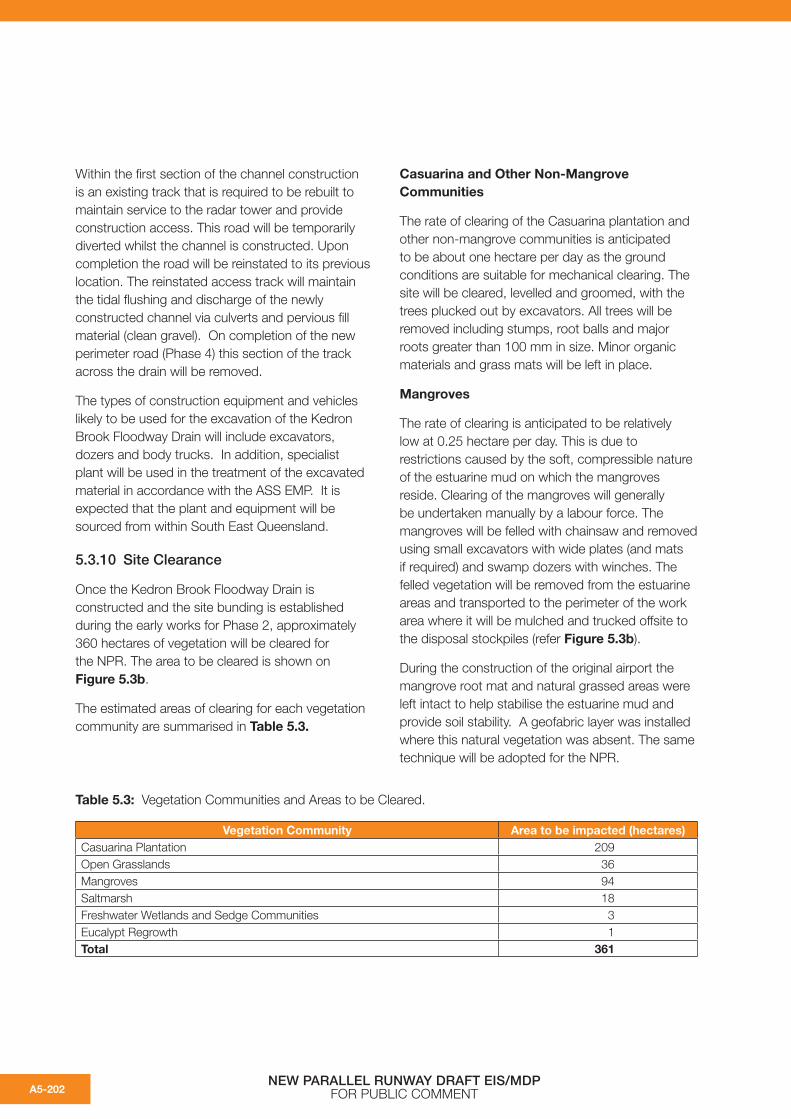
5.3.10 Site Clearance
Once the Kedron Brook Floodway Drain is constructed and the site bunding is established during the early works for Phase 2, approximately 360 hectares of vegetation will be cleared for the NPR. The area to be cleared is shown on Figure 5.3b.
The estimated areas of clearing for each vegetation community are summarised in Table 5.3.
Casuarina and Other Non-Mangrove Communities
The rate of clearing of the Casuarina plantation and other non-mangrove communities is anticipated to be about one hectare per day as the ground conditions are suitable for mechanical clearing. The site will be cleared, levelled and groomed, with the trees plucked out by excavators. All trees will be removed including stumps, root balls and major roots greater than 100 mm in size. Minor organic materials and grass mats will be left in place.
Mangroves
The rate of clearing is anticipated to be relatively low at 0.25 hectare per day. This is due to restrictions caused by the soft, compressible nature of the estuarine mud on which the mangroves reside. Clearing of the mangroves will generally be undertaken manually by a labour force. The mangroves will be felled with chainsaw and removed using small excavators with wide plates (and mats if required) and swamp dozers with winches. The felled vegetation will be removed from the estuarine areas and transported to the perimeter of the work area where it will be mulched and trucked offsite to the disposal stockpiles (refer Figure 5.3b).
During the construction of the original airport the mangrove root mat and natural grassed areas were left intact to help stabilise the estuarine mud and provide soil stability. A geofabric layer was installed where this natural vegetation was absent. The same technique will be adopted for the NPR.
Table 5.3: Vegetation Communities and Areas to be Cleared.
Vegetation Community Area to be impacted (hectares)Casuarina Plantation 209Open Grasslands 36Mangroves 94Saltmarsh 18Freshwater Wetlands and Sedge Communities 3Eucalypt Regrowth 1Total 361
NEW PARALLEL RUNWAY DRAFT EIS/MDP FOR PUBLIC COMMENTA5-202

Cleared Vegetation Management
The cleared vegetation will be mulched on-site using a tubgrinder (or similar) mounted on the rear of a semitrailer that will be moved around the site. The tubgrinder will be located in an area surrounded by temporary bunding, which will be constructed to manage stormwater runoff. The felled vegetation will be pushed to the tub grinder to enable grinding with the mulched material then transported to the disposal stockpile site.
The types of construction equipment and vehicles likely to be used will include excavators, swamp dozers, semi trailer mounted tub grinders and body trucks. It is expected that the plant and equipment will be sourced from within South East Queensland.
The material after being mulched at the clearing site will be transported by 6x6 wheeled trucks to a common stockpile location. A 40 hectare area within the airport boundary will be allocated for this purpose. The stockpiles will require the long term management strategies for the control of:
• Leachate;
• Pest management; and
• Spontaneous combustion.
Any leachate produced during the decomposition process will be collected and disposed of as appropriate. Spontaneous combustion will be minimised by restricting the height of the mulched vegetation stockpiles to under 4 m and the pests will be managed by minimising the residence time of the material at the disposal site.
There are a number of potential opportunities to recycle the mulched vegetation that will be investigated further. These include:
• Use on-site as mulch;
• Transport off-site to be recycled as a biofuel; and
• Use Casuarina and other non-mangrove mulch during the reclamation phase on exposed soil as a soil stabilisation agent.
The high moisture content of the mulched mangrove material means that it is not suitable for reuse as a biofuel. Consequently, the mangrove
mulch will be segregated from the Casuarina and non-mangrove mulch and reused on-site.
If the material is disposed of off-site then it will need to be confirmed as Red Imported Fire Ant (RIFA) free.
The burning of material will not be permitted on-site.
5.3.11 Groundwater Treatment Trench
A groundwater treatment trench is required to intercept the groundwater seepage prior to it entering the Kedron Brook Floodway in accordance with the ASS EMP.
This groundwater treatment trench will extend the full length of the runway fill platform along the western side of the site (refer Figure 5.3b). The trench will be between 6 m and 12 m wide with a triangular cross-section having a maximum depth of 1.5 m. The trench will be constructed following the completion of the primary bunds.
The groundwater treatment trench is designed to be a permanent feature that provides protection to acid groundwater infiltration into Kedron Brook Floodway. The proximity of the groundwater trench to the sand platform will vary along its length. It will be located closer to the reclaimed sand platform where the sand platform is lower in height and where the sand fill platform is immediately adjacent to Kedron Brook Floodway.
The alignment of the lime trench will be chosen to minimise clearing and to maximise the use of existing access roads on the airport.
The typical construction sequence for this groundwater treatment trench will be:
1. Clear the vegetation along the line of the trench as described in section 5.3.10;
2. Excavate the trench and treat the material in accordance with the EMF (refer Chapter B14);
3. Line the trench with coarse plastic mesh;
4. Fill the trench with graded lime;
5. Cover the lime filled trench with geofabric;
6. Place imported coarse gravel along the eastern side of the trench to cover the geofabric material; and
NEW PARALLEL RUNWAY DRAFT EIS/MDP FOR PUBLIC COMMENT A5-203
7. Place and compact the treated spoil over the remaining section of the lime filled trench.
The types of construction equipment and vehicles likely to be used for the construction of the groundwater treatment trench will include dozers, rollers, graders and excavators. It is expected that the plant and equipment will be sourced from within South East Queensland.
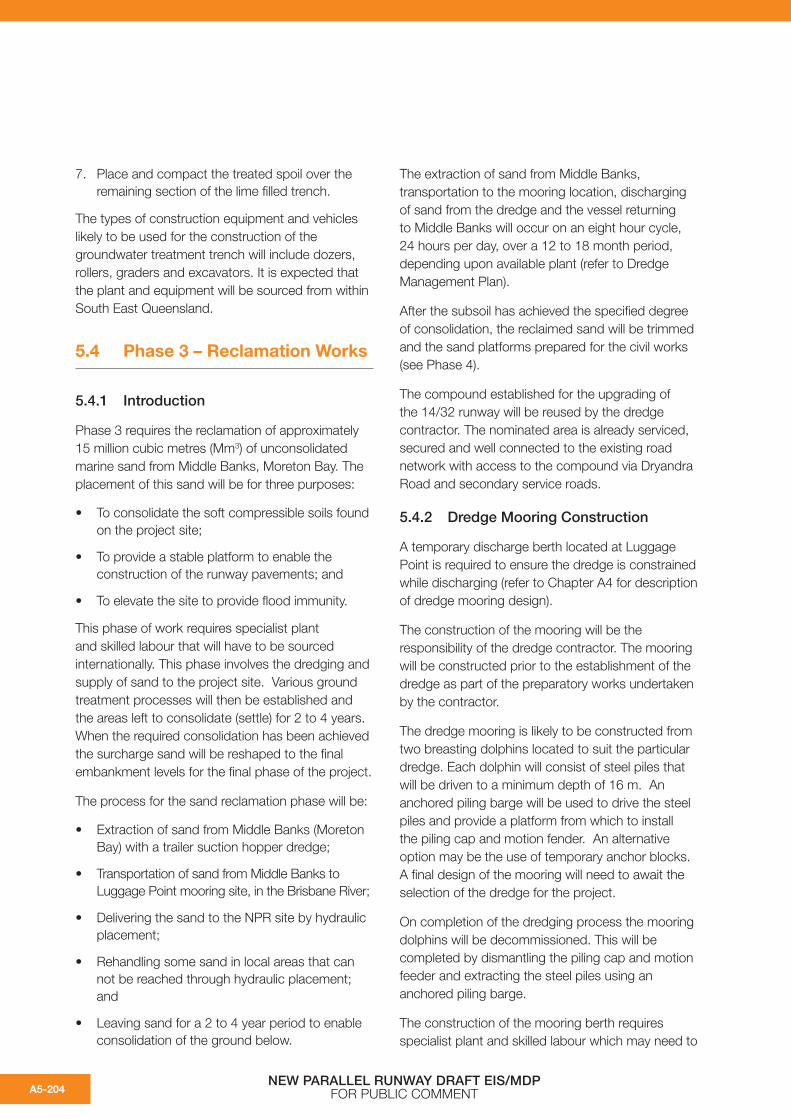
5.4 Phase 3 – Reclamation Works
5.4.1 Introduction
Phase 3 requires the reclamation of approximately 15 million cubic metres (Mm3) of unconsolidated marine sand from Middle Banks, Moreton Bay. The placement of this sand will be for three purposes:
• To consolidate the soft compressible soils found on the project site;
• To provide a stable platform to enable the construction of the runway pavements; and
• To elevate the site to provide flood immunity.
This phase of work requires specialist plant and skilled labour that will have to be sourced internationally. This phase involves the dredging and supply of sand to the project site. Various ground treatment processes will then be established and the areas left to consolidate (settle) for 2 to 4 years. When the required consolidation has been achieved the surcharge sand will be reshaped to the final embankment levels for the final phase of the project.
The process for the sand reclamation phase will be:
• Extraction of sand from Middle Banks (Moreton Bay) with a trailer suction hopper dredge;
• Transportation of sand from Middle Banks to Luggage Point mooring site, in the Brisbane River;
• Delivering the sand to the NPR site by hydraulic placement;
• Rehandling some sand in local areas that can not be reached through hydraulic placement; and
• Leaving sand for a 2 to 4 year period to enable consolidation of the ground below.
The extraction of sand from Middle Banks, transportation to the mooring location, discharging of sand from the dredge and the vessel returning to Middle Banks will occur on an eight hour cycle, 24 hours per day, over a 12 to 18 month period, depending upon available plant (refer to Dredge Management Plan).
After the subsoil has achieved the specified degree of consolidation, the reclaimed sand will be trimmed and the sand platforms prepared for the civil works (see Phase 4).
The compound established for the upgrading of the 14/32 runway will be reused by the dredge contractor. The nominated area is already serviced, secured and well connected to the existing road network with access to the compound via Dryandra Road and secondary service roads.
5.4.2 Dredge Mooring Construction
A temporary discharge berth located at Luggage Point is required to ensure the dredge is constrained while discharging (refer to Chapter A4 for description of dredge mooring design).
The construction of the mooring will be the responsibility of the dredge contractor. The mooring will be constructed prior to the establishment of the dredge as part of the preparatory works undertaken by the contractor.
The dredge mooring is likely to be constructed from two breasting dolphins located to suit the particular dredge. Each dolphin will consist of steel piles that will be driven to a minimum depth of 16 m. An anchored piling barge will be used to drive the steel piles and provide a platform from which to install the piling cap and motion fender. An alternative option may be the use of temporary anchor blocks. A final design of the mooring will need to await the selection of the dredge for the project.
On completion of the dredging process the mooring dolphins will be decommissioned. This will be completed by dismantling the piling cap and motion feeder and extracting the steel piles using an anchored piling barge.
The construction of the mooring berth requires specialist plant and skilled labour which may need to
NEW PARALLEL RUNWAY DRAFT EIS/MDP FOR PUBLIC COMMENTA5-204

be sourced nationally depending on the availability within South East Queensland.
Scour and erosion of the shoreline and river bed adjacent to the proposed mooring may occur as a result of the dredge manoeuvring within the swing basin (refer to Chapter A4). To ensure the shoreline and river bed are protected, concrete matting (or similar treatment) will be installed. This matting will be rolled out from a piling barge and weighted down with the placement of concrete weights and rock. The concrete matting or scour protection is a temporary structure and will be removed following the completion of the dredging/reclamation phase.
All works carried out within the existing swing basin will be in consultation with the Harbour Master to ensure that safe continuous operation of the port during construction of the temporary structures.
5.4.3 Sand Delivery Pipeline Construction
The dredged sand will be transported to the reclamation site through a sealed pipeline as described in Chapter A4.
An access track and low height embankment is required for the length of the pipeline and will be constructed from imported or recycled granular materials from site. The granular material will be delivered to the pipeline corridor by truck to allow the road and embankment to be formed and compacted. The pipeline sections will then be positioned and connected to complete the delivery pipeline.
The discharge pipeline is required to cross the Luggage Point Wastewater Treatment Plant’s (WWTP) twin concrete effluent channels (refer to Chapter A4 for pipeline design and temporary structures). To elevate the pipeline over the effluent channels, temporary earth embankments fronted by gabion walls will be constructed from compacted suitable fill. A 25 m welded section of pipeline and a prefabricated steel truss pedestrian/pipe bridge section will be lifted by a crane over the channels and lowered on to the embankments to complete the channel crossing. On completion of the reclamation process the welded section of pipeline, pedestrian walkway and embankments will be removed and the site restored.
At the boundary of Luggage Point WWTP is an existing airport drain, known as Jubilee Creek. The construction of the dredge pipeline crossing this drain will be similar to the effluent channel crossing described above. On completion of the reclamation process the pipeline, bridge structure and supporting embankments will be removed, the ground restored and mangroves allowed to recolonise.
Construction of the pipe route may involve disturbance of fill materials placed during previous airport developments or during operation of the Luggage Point WWTP. Specifically, the pipe route traverses an area used to dispose biosolids from the wastewater treatment plant. The biosolids disposal area is capped and the pipe route will traverse this area with minimal disturbance. All disturbed materials will be tested and treated appropriately during this operation.
As the 14/32 runway will be operational during dredging, additional protective works are required to protect the dredge pipe from aircraft loading and reduce the risk of disruption to airport operations during dredging. A section of dredge pipeline will be installed beneath the taxiway link during Phase 1 of the project, as described in section 5.2.9.
The types of construction equipment and vehicles likely to be used for the preparation and installation of the pipeline and associated structures will include cranes, scrapers, excavators, body trucks, rollers, dozers and graders. It is expected that the plant and equipment will be sourced from within South East Queensland.
Upon completion of sand delivery, the pipeline will be recovered and removed with trucks and excavators and taken from the site. The pipeline will remain the property of the contractor and will have residual value and will likely be reused on another project. The pipeline gravel embankment, including the 5 m wide access road will be salvaged as the disestablishment process proceeds and the gravel materials recycled and reused in the construction of the runway. The dredge pipeline beneath the proposed taxiway links to 14/32 will remain in place and either be capped to allow for future use as a service duct or filled with sand or concrete if the pipe is to be abandoned.
NEW PARALLEL RUNWAY DRAFT EIS/MDP FOR PUBLIC COMMENT A5-205

5.4.4 Sand Placement
Typically, dredged sand will be placed directly from the dredge to its final location on the site with the minimum of manual or machine handling. For the majority of the project, hydraulic placement in this manner is likely. Hydraulic placement of sand is only possible while the dredge is moored and is characterised by large volumes of sand and water being delivered over a short time period. This style of delivery is not suitable for filling around existing infrastructure or in small areas where the volume of material from the dredge head is excessive.
In constrained areas, sand will be delivered as close as practical to the required site, placed in stockpiles and then manually rehandled into the desired location. As such, manual handling can take place over extended periods allowing the contractor to have better control over the location and quantity of fill being placed. Manual rehandling of sand will occur throughout the reclamation process (Phase 3).
In constrained areas, sand will be delivered as close as practical to the required site and then manually rehandled into place. The hydraulic placement of the sand needs to be applied in a short period of time (during vessel discharging) whereas the manually rehandling of the sand will be undertaken continuously throughout Phase 3.
The types of construction equipment and vehicles used for the handling of the dredged sand will include swamp dozers, scrapers, loaders and body trucks. It is expected that the plant and equipment will be sourced from within South East Queensland.
5.4.5 Reclamation Sequence
A number of ground treatment methods will be used during the construction of the NPR to remove primary settlement as described in Chapter A4. Different ground treatment methods will be required across the site in response to the different ground conditions. These ground treatments will be:
• Surcharging (to various heights) with wick drains;
• Surcharging (to various heights) without wick drains; and
• Preloading.
Vacuum consolidation, proposed for ground treatment for the 14/32 upgrading works (refer Phase 1) is not proposed for the remainder of the project.
The reclamation and ground treatment methods and the areas over which they apply vary across the site. Priority in applying the preload or surcharge is given to those areas with the poorest ground conditions that require the longest period for consolidation and settlement. Typically, the areas requiring the installation of wick drains and surcharging require the longest consolidation time and these areas will be completed as a priority.
Surcharging with Wick Drains
Wick drains are vertical drains (pipes) that accelerate the consolidation of soft materials by improving drainage to the ground water contained within the soft soils. Wick drains are typically less than 100 mm in diameter and made from a polyethylene tube. Wick drains will be installed in a grid pattern through a one metre sand working platform. Installation will be using specific equipment, mounted on a crane, which pushes the wick drains into the soils to a depth similar to the depth of compressible materials (more than 30 m in some places).
Surcharging describes the placement of fill material over the wick drains. Surcharging is the application of a load to the area to further accelerate the consolidation process. The surcharge heights range from 5.5 m to 6.5 m, depending upon the ground treatment required. The surcharge will be placed hydraulically where possible and trimmed using mechanical earthmoving equipment.
The types of construction equipment and vehicles for the installation of wick drains will include wick drain installers, cranes and earthmoving equipment such as dozers and graders. It is expected that the plant and equipment will be sourced from within South East Queensland.
NEW PARALLEL RUNWAY DRAFT EIS/MDP FOR PUBLIC COMMENTA5-206

Surcharging without Wick Drains
For construction of areas requiring surcharge without wick drains the surcharge platform will be placed hydraulically or rehandled from stockpiles to the full surcharge height as noted on the drawing.
Preloading
Preloading is the placement of fill material to a predetermined height and allowing settlement to occur, reducing the height of the preload to the final construction level. Preload platforms will be placed hydraulically or rehandled from stockpiles to the full surcharge height as noted on the drawings.
5.4.6 Consolidation Period
Primary consolidation of areas with surcharge treatment is expected to be achieved after a period of between 2 to 4 years from the completion of the preloading and surcharge construction.
Settlement plates will be installed at the beginning of the consolidation period and measuring equipment will be mounted on a reader post outside the consolidation area. A network of gravel tracks will be established across the reclaimed sand to allow access to the survey points and for maintenance of consolidation measuring equipment (refer Figure 5.4c). When the required amount of consolidation and associated ground settlement has been achieved, the pavements and civil works phase of the project will begin (Phase 4).
The sand platforms will be stabilised to reduce potential erosion during the consolidation period. Mulched Casuarina and other non-mangrove vegetation, recycled water for suppression or a water based latex-acrylic stabilising agent will be used to minimise erosion.
5.4.7 Reclamation Supernatant Management
Hydraulic placement of sand fill material used throughout the reclamation activities results in the generation of large volumes of reclamation supernatant. Sand material is delivered to the reclamation site in a sand-water ratio of approximately 1:4. Supernatant water generated during reclamation will be managed within the reclamation cells and sediment ponds (refer Chapter A4 for description of sediment ponds).
Confined sub-areas (reclamation cells) will be constructed within the main perimeter bunds during reclamation for the NPR. The reclamation cells define the area for hydraulic placement of sand and control the movement of supernatant water within the construction area (refer Figure 5.4a). Cells will be constructed initially using shallow earth mounds over in situ soils, and will be reformed as sand fill materials become available during the reclamation.
The internal boundary of individual cells is defined by earth mounds and the cells will be hydraulically connected with a weir structure that allows water to be directed from the active cell to the subsequent cells in the filling sequence or directly to the sediment pond. The final reclamation cell is connected to the sediment pond and supernatant from filling of the final cell within a sequence will be directed to the pond. The connection of reclamation cells and the sediment ponds defines the system for storage and treatment of supernatant water during the reclamation. Discharge to Kedron Brook Floodway and Serpentine Inlet receiving waters is controlled at the outlet of the sediment ponds.
NEW PARALLEL RUNWAY DRAFT EIS/MDP FOR PUBLIC COMMENT A5-207

Processes that influence reclamation supernatant characteristics will vary between different phases of hydraulic placement in the construction area and are dependent upon potential erosion of in situ soils during reclamation. Five main reclamation phases include (refer Figure 5.4b):
a) Initial hydraulic placement of sand fill on in situ soils with best-practice erosion controls as outlined in Section 5.4.9 (start-up condition);
b) Hydraulic placement on established sand platforms, with exposure of in situ soils to supernatant within the reclamation cell;
c) Hydraulic placement on established sand platforms within reclamation cells that have ponded water to control scour;
d) Hydraulic placement within reclamation cells nearing completion, where there is insignificant storage and sedimentation occurring within the active cell; and
e) Mechanical placement of sand fill to sediment ponds during pond decommissioning.
Phase (a) will occur only where the contractor commences reclamation in a cell where no previous filling has been undertaken and filling has not been undertaken in adjacent cells. Reclamation phases (b) and (c) will be common to each reclamation cell. Phase (d) will occur only when filling is nearing completion within the catchment of either of the two sediment ponds. Once reclamation is completed, earthmoving equipment will be used to fill the sediment ponds with stockpiled sand material (Phase (e)). This activity is expected to occur following or during the final construction phase of the runway. Ponds are expected to be decommissioned once the operational stormwater system, including operational water quality measures, is in place.
During initial hydraulic placement of sand fill into reclamation cells (phase (a) start-up condition) there is potential for erosion of in situ soils that are not protected by overlying sand layers. There are a number of best-practice construction methods that will assist in reducing the erosion of in situ soils and will be adopted by the reclamation contractor during this initial reclamation phase (examples shown in section 5.4.9), however the start-up condition will constitute the greatest potential for erosion of in
situ soils. The duration of the start-up condition is expected to be less than one day.
Following initial placement of a small sand platform at the end of the dredge pipe, the potential for erosion of in situ soils is reduced as the platform prevents exposure of in situ soils to the highly erosive velocities at the outfall. During this phase (phase (b), shortly following start-up) there will be insufficient supernatant volume to establish ponded water over the in situ soils and supernatant delivered to the reclamation cell will flow slowly over in situ soils and begin to fill the cell. The erosion potential of this phase is significantly lower than the start-up filling and will be dominated by erosion of in situ soils as supernatant fills the reclamation cells. Phase (b) is expected to have a duration of approximately one week within each reclamation cell.
After supernatant begins to pond within the reclamation cell, the potential for erosion of in situ soils is further reduced as supernatant velocity over in situ soils is reduced (phase (c)). In situ soils will remain exposed below ponded water at the extents of the reclamation cell, and suspension of particles will result from scour of in situ soils and wind-propagated wave effects, however the potential for erosion is reduced. This condition will be experienced for the predominant period of reclamation. The duration of phase (c) is expected to be approximately 4 - 6 weeks within each reclamation cell.
When reclamation is nearing completion within each cell, a small sand platform will be mechanically placed in the subsequent cell and ponded supernatant will be allowed to discharge from the active cell to the subsequent cell. The dredge pipe will then advance directly to the subsequent cell and commence filling. Accordingly, the high erosion potential of start-up filling within cells is avoided when adjacent cells are filled consecutively, and filling in the subsequent cell is defined by phases (b) and (c).
When the sequence of filling reclamation cells is nearing completion the active cell will be directly adjacent the sediment pond and there is limited capacity for ponding and sedimentation within the cell (phase (d)). Under this condition, supernatant will be discharged directly from the reclamation cell to the sediment pond. The reclamation site will
NEW PARALLEL RUNWAY DRAFT EIS/MDP FOR PUBLIC COMMENTA5-208

be completely covered in sand material, with low potential for erosion of in situ soils. The duration of phase (d) is expected to be approximately one week for each reclamation cell.
5.4.8 Sediment Pond Operation
The following key points describe the operation of the sediment ponds during reclamation. A specific discussion of water quality during the construction process is provided in Chapter B8.
• The maximum storage volume provided within each pond is 230,000 m3;
• Controlled discharge from the ponds will occur during the higher half of the tide for discharge to Serpentine Inlet Drain allowing water quality impacts and erosion of the receiving drainage channels to be managed;
• The ponds provide storage capacity that allows supernatant to be contained during low tide conditions (below mean sea level) controlled by an adjustable weir structure (weir box);
• Pond discharge will be controlled to optimise treatment of supernatant and provide sufficient storage to accommodate the receiving supernatant;
• The sediment ponds will be controlled to retain a permanent pool volume of approximately 115,000 m3. This pool will promote removal of suspended particles from supernatant and reduce resuspension of settled particles;
• The average rate of discharge from the sediment ponds is approximately 8 m3/s throughout the reclamation period (based on discharge during high tide conditions);
• Discharge velocities in major tidal channels are typically less than 1 m/s;
• Discharge from the ponds may be undertaken on a continuous 24 hour basis (during all tidal conditions) if erosion of bed materials in receiving drainage channels is adequately managed by controlling discharge velocity;
• Rock protection is included locally around he discharge structure to control erosion of the bed materials during discharge of reclamation supernatant;
• A number of erosion control measures will be employed by the reclamation contractor to reduce the potential erosion of in situ soils throughout the reclamation period (refer section 5.4.9);
• The concentration of total suspended solids in discharge from the sediment ponds will fluctuate during different phases of reclamation. Each phase of reclamation will adopt all reasonable and practicable erosion control measures to minimise the suspended solids;
• Following application of suitable best practice erosion control measures and storage of the supernatant within the sediment ponds the average total suspended solids concentration discharged from the sediment ponds over the total reclamation period is approximately 50 mg/L;
• Monitoring of the total suspended soils in the discharge from the ponds will occur during the reclamation cycle in accordance with the water quality management plan in the EMF (Chapter B14).
5.4.9 Erosion Control Practices During Reclamation
Direct hydraulic placement of sand fill materials on exposed in situ soils during initial reclamation stages (phase (a) in section 5.4.7) has the potential to cause erosion of in situ soil. A combination of erosion control practices will be adopted during reclamation to reduce the potential for erosion of in situ soils. Erosion will be dominant during the initial stages of fill placement, prior to establishing a sand platform over exposed in situ soil.
Techniques that will be used to control erosion during initial stages of reclamation include:
• Protection of in situ soils with geotextile membrane to prevent soil erosion;
• Use of multiple dredge discharge pipes during initial fill placement to reduce flow rates and velocities in the initial phase;
• Use of spreading devices for pipe ends to disperse the discharge over a greater area;
NEW PARALLEL RUNWAY DRAFT EIS/MDP FOR PUBLIC COMMENT A5-209
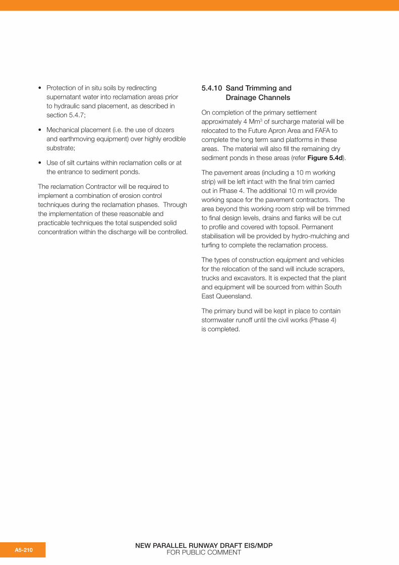
• Protection of in situ soils by redirecting supernatant water into reclamation areas prior to hydraulic sand placement, as described in section 5.4.7;
• Mechanical placement (i.e. the use of dozers and earthmoving equipment) over highly erodible substrate;
• Use of silt curtains within reclamation cells or at the entrance to sediment ponds.
The reclamation Contractor will be required to implement a combination of erosion control techniques during the reclamation phases. Through the implementation of these reasonable and practicable techniques the total suspended solid concentration within the discharge will be controlled.
5.4.10 Sand Trimming and Drainage Channels
On completion of the primary settlement approximately 4 Mm3 of surcharge material will be relocated to the Future Apron Area and FAFA to complete the long term sand platforms in these areas. The material will also fill the remaining dry sediment ponds in these areas (refer Figure 5.4d).
The pavement areas (including a 10 m working strip) will be left intact with the final trim carried out in Phase 4. The additional 10 m will provide working space for the pavement contractors. The area beyond this working room strip will be trimmed to final design levels, drains and flanks will be cut to profile and covered with topsoil. Permanent stabilisation will be provided by hydro-mulching and turfing to complete the reclamation process.
The types of construction equipment and vehicles for the relocation of the sand will include scrapers, trucks and excavators. It is expected that the plant and equipment will be sourced from within South East Queensland.
The primary bund will be kept in place to contain stormwater runoff until the civil works (Phase 4) is completed.
NEW PARALLEL RUNWAY DRAFT EIS/MDP FOR PUBLIC COMMENTA5-210

NEW PARALLEL RUNWAY DRAFT EIS/MDPFOR PUBLIC COMMENT
NEW PARALLEL RUNWAY DRAFT EIS/MDPFOR PUBLIC COMMENT
Figure 5.4a: Preliminary Reclamation – Typical Cell Partitioning.
A5-211

NEW PARALLEL RUNWAY DRAFT EIS/MDPFOR PUBLIC COMMENT
NEW PARALLEL RUNWAY DRAFT EIS/MDPFOR PUBLIC COMMENT
Figure 5.4b: Preliminary Reclamation – Typical Arrangement.
A5-212

NEW PARALLEL RUNWAY DRAFT EIS/MDPFOR PUBLIC COMMENT
NEW PARALLEL RUNWAY DRAFT EIS/MDPFOR PUBLIC COMMENT
Figure 5.4c: Phase 3 – Reclamation Works Consolidation Period.
A5-213

NEW PARALLEL RUNWAY DRAFT EIS/MDPFOR PUBLIC COMMENT
NEW PARALLEL RUNWAY DRAFT EIS/MDPFOR PUBLIC COMMENT
Figure 5.4d: Sand Trimming and Drainage Channels.
A5-214

5.5 Phase 4 – Pavement and Civil Works
5.5.1 Introduction
Phase 4 is the final pavements and civil works phase for the project. These activities have been grouped together as they are standard construction activities. Some of the activities are interdependent and will require careful scheduling to ensure that they are constructed in an efficient manner.
After the completion of the consolidation process described in Phase 3, the NPR project site will be prepared for the civil works and pavement construction.
Phase 4 consists of many elements which are interdependent. Elements that will be addressed during this phase include the following activities:
Site Preparation
• Construction compound;
• Material storage area;
• Site access.
Drainage Installation
Runway and Taxiway Pavement Works
• Pavement staging;
• Sub-grade construction;
• Flexible pavments; and
• Concrete pavements.
Services
• Electrical installations;
• Aerodrome lighting equipment rooms;
• Electrical service corridors; and
• Airfield lighting conduits.
Associated Runway Facilities
• Movement area guidance signs;
• Aerodrome ground lighting;
• Pavement markings;
• Dryandra Road tunnel;
• Approach lighting structure; and
• Perimeter roads.
Runway Commissioning
• Disestablishing the construction site; and
• Commissioning of runway.
5.5.2 Site Preparation
A construction compound, site access and material storage areas will be established to enable the construction of the pavement and civil works to commence as described below.
5.5.3 Construction Compound
It is proposed to construct a large fenced compound on the sand platform that will be located at the Future Apron Area as shown on Figure 5.5a. The compound will provide a secure location for the offices and the storage of materials. The main access road to the NPR construction compound will be via the new northern access road and a network of temporary site access roads.
The types of construction equipment and vehicles likely to be used to establish the compound will include excavators or skid-steer loaders, low loaders and cranes. It is expected that the plant and equipment will be sourced from within South East Queensland.
The location selected for the site compound has taken into account:
• Delivery of the raw materials to the batching plants;
• Stockpiles of raw materials;
• Removal of excavated material; and
• Temporary site offices, amenity facilities, maintenance and storage buildings.
The compound will include:
• Significant storage and stockpile areas;
• Gravel blending plants;
• Concrete batch plant;
NEW PARALLEL RUNWAY DRAFT EIS/MDP FOR PUBLIC COMMENT A5-215

• Asphalt batch plant;
• Site offices;
• Workforce amenity facilities;
• Maintenance areas; and
• Storage buildings.
The critical services (power, communication, water and sewer) will be available from the existing services within the airport and will be extended to the construction compound. Further investigations will be required to determine the capacity available for each service type.
5.5.4 Material Storage and Production
A significant proportion of the concrete will be used for pavement construction with a small quantity for the culverts and pipe work. Early procurement and stockpiling of precast pipes and culvert units at the compound will provide certainty of supply during a period of high construction activity throughout South East Queensland.
Indicative quantities and sources for key construction materials are shown in Table 5.5. It is preferred to source these materials from local suppliers.
Table 5.5 – Material Quantities and Sources.
Material Quantity (rounded to the nearest 500)
Source
Sub-base 100,500 m3 Land based quarryBase course 188,500 m3 Land based quarrySelected fill 110,000 m3 Land based quarryConcrete 97,000 m3 Batched on-siteAsphalt 27,000 m3 Batched on-siteCrushed rock/gravel 25,000 m3 Land based quarry
Due to the large quantities of materials required, two gravel blending mills will be established for the production of the pavement gravels. The raw material will be stockpiled on-site with at least four weeks supply to ensure continuous production and reduce exposure to supply risks.
It is proposed to have an on-site batching facility for both concrete and asphalt production. The batching plants will be established on-site after the reclamation has been completed. Recycled material will be reused wherever possible and a quality management system implemented to minimise waste generation during this manufacturing process.
An area of 85,000 m2 will be required for the two gravel blending plants, the concrete batch plant and the asphalt batch plant. The stockpile sites will need to be of sufficient size to accommodate 5,000 m3 of each raw material. The size of these stockpile areas was determined based on the outputs required from the construction programme and an allowance to mitigate any delays in delivery of materials that may be experienced due to predicted high demand throughout South East Queensland.
The compound will have sufficient space to allow several trucks to queue on-site while waiting to be loaded and unloaded. Washing facilities for vehicles leaving the site will be considered to ensure the public road network is kept free from construction debris. All trucks carrying loose material will have their loads covered to ensure dust and debris is contained within the truck.
5.5.5 Site Access
Construction site traffic will include:
• Workforce transportation;
• Haulage of excavated material;
• Importation of construction materials and equipment; and
• Site visitors.
This will result in a variety of vehicle types travelling to and from the construction site on a daily basis including cars, vans, semi trailers and trucks.
NEW PARALLEL RUNWAY DRAFT EIS/MDP FOR PUBLIC COMMENTA5-216

The source and destinations for the transportation of materials and equipment will vary and will not be determined until the method of procurement and contractors are selected. The Pacific Motorway and Gateway Motorways will be the main transportation routes for material being transported from the south. The Bruce Highway and the Gateway Motorway will be the main transportation routes for material being transported from the north and the Warrego Highway, Ipswich Motorway, Logan Motorway and the Gateway Motorway route will be utilised if the material is been transported from the west.
For all potential haul routes the Gateway Motorway will be used. The Gateway Motorway is the main north-south arterial spine serving the Australian TradeCoast (ATC), an area that includes the airport, seaport and the established commercial hub at the mouth of the Brisbane River.
The Gateway Bridge and sections of the Gateway Motorway are at or approaching capacity with motorists currently experiencing same delays in the morning and evening peaks. The Gateway Motorway from Mount Gravatt-Capalaba Road to Nudgee Road will be upgraded from late 2006 to late 2011.
Airport Drive is a dual lane private road of arterial standard with public access which has been recently upgraded to six lanes between the Gateway Motorway interchange and the access to Number 1 Airport Drive precinct. It currently provides the only major road link to the Brisbane
Airport and will be used as one route for traffic entering and leaving the site.
The new northern access is designed to leave the Gateway Upgrade Project along a new road alignment which runs parallel to the existing Airport Drive to the north of the Domestic Terminal. This new road network will be available for access to the construction compound and will be the preferred route. A temporary site access road will be constructed from this road to access the construction compound.
This temporary access road will be subjected to large volumes of traffic and heavy loads and therefore will be constructed as if permanent.
The working platform will be laid on the cleared surface using clean gravels to a depth of about 350 mm. The access road will be sealed and drainage installed which will be connected into the existing drainage system.
To facilitate the delivery of the project this road will be constructed during Phase 3, the reclamation phase, of the project in readiness for commencing Phase 4 and establishment of the construction camp.
See Chapter B14 for the Environmental Management Plans Framework developed for the design phases of the project.
5.5.6 Drainage
To complete the drainage system for the NPR project requires the construction of:
• The western secondary tidal channel which connects to Kedron Brook Floodway Drain; and
• Culverts below the new taxiway pavement to connect the open drainage channels, completing the drainage network.
The secondary tidal channel is located in the south west corner of the site and connects to the Kedron Brook Floodway Drain (refer Figure 5.5a). This trapezoidal open channel is 780 m long and has a base width of 10 m. This drain will direct flows from the western side of the new runway and taxiway system into the floodway via Kedron Brook Floodway Drain.
To minimise the construction and environmental risk, the construction of this secondary tidal channel will follow the same construction stages as described in section 5.3.9. Approximately 25,000 m3 of potential or actual acid sulfate soil will be excavated from the channel and transferred to a treatment area. The material will be treated (neutralised with agricultural lime) and re-used on-site as fill material (refer to ASS EMP).
A series of culverts are required below the taxiway pavement to connect the open drainage channels formed during the final sand trimming at the end of Phase 3. These culverts will complete the drainage network and will be installed prior to the taxiway pavements being constructed.
NEW PARALLEL RUNWAY DRAFT EIS/MDP FOR PUBLIC COMMENT A5-217

The typical construction procedure for the installation of the culverts will be:
• Excavate trench with conventional equipment through the sand platform;
• Dispose of the surplus sand in the future apron area or future aviation facilities area;
• Any works outside the main sand footprint may expose existing sub-grade material. If exposed the sub grade material will be checked for actual and potential acid sulfate soil and managed appropriately;
• If contamination is observed then the material will be transported to the disposal site and segregated from the other stockpiles. Depending on the type of contamination the appropriate treatment and disposal strategy will be implemented;
• The specified bedding material will be prepared to receive the culverts;
• The culverts will be laid with excavators or cranes, as required, and backfilled;
• Concrete end structures will be cast in situ, utilising the on-site concrete batch plant, precast units may be used if available; and
• Inverts and location of the culverts will be surveyed ‘as constructed’.Any water that infiltrates the excavation will be pH adjusted with agricultural lime to between 6.5 and 8.5 and discharged on-site.
The types of construction equipment and vehicles likely to be used for the installation of the drains will include excavators, skid-steer loaders, compactors and cranes. It is expected that the plant and equipment will be sourced from within South East Queensland.
5.5.7 Pavement Construction Staging
The NPR will provide aircraft movement capacity for the projected aircraft demand. However, the complete taxiway system will not be required in the short to medium term. In addition the taxiway development will be in response to terminal and apron development over time to the north and west of the existing terminal and apron.
Construction staging for the parallel taxiway system aims to minimise immediate capital cost associated with the construction of the NPR and associated infrastructure (refer Chapter A4, section 4.6). The staging of runway and taxiway infrastructure will need to account for a range of aviation, engineering and constructability considerations.
The preliminary design for the pavements is based on conventional unbound granular, asphalt surfaced flexible pavement and conventional rigid pavement (plain jointed concrete slabs) similar to those used for the current pavements found on the 01/19 runway. These have been adopted for this project due to the overall good performance of the existing Brisbane Airport pavements. The preliminary design pavement details are shown on Figures 5.5b1 and 5.5b2.
The pavement construction is anticipated to start at the northern end of the project site. In all areas, the NPR and taxiways will be constructed on the sand formation.
NEW PARALLEL RUNWAY DRAFT EIS/MDP FOR PUBLIC COMMENTA5-218
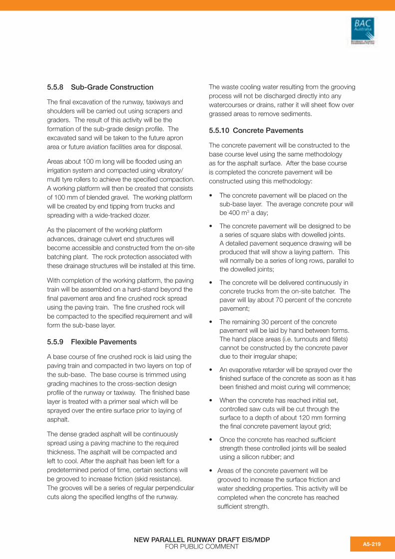
5.5.8 Sub-Grade Construction
The final excavation of the runway, taxiways and shoulders will be carried out using scrapers and graders. The result of this activity will be the formation of the sub-grade design profile. The excavated sand will be taken to the future apron area or future aviation facilities area for disposal.
Areas about 100 m long will be flooded using an irrigation system and compacted using vibratory/multi tyre rollers to achieve the specified compaction. A working platform will then be created that consists of 100 mm of blended gravel. The working platform will be created by end tipping from trucks and spreading with a wide-tracked dozer.
As the placement of the working platform advances, drainage culvert end structures will become accessible and constructed from the on-site batching plant. The rock protection associated with these drainage structures will be installed at this time.
With completion of the working platform, the paving train will be assembled on a hard-stand beyond the final pavement area and fine crushed rock spread using the paving train. The fine crushed rock will be compacted to the specified requirement and will form the sub-base layer.
5.5.9 Flexible Pavements
A base course of fine crushed rock is laid using the paving train and compacted in two layers on top of the sub-base. The base course is trimmed using grading machines to the cross-section design profile of the runway or taxiway. The finished base layer is treated with a primer seal which will be sprayed over the entire surface prior to laying of asphalt.
The dense graded asphalt will be continuously spread using a paving machine to the required thickness. The asphalt will be compacted and left to cool. After the asphalt has been left for a predetermined period of time, certain sections will be grooved to increase friction (skid resistance). The grooves will be a series of regular perpendicular cuts along the specified lengths of the runway.
The waste cooling water resulting from the grooving process will not be discharged directly into any watercourses or drains, rather it will sheet flow over grassed areas to remove sediments.
5.5.10 Concrete Pavements
The concrete pavement will be constructed to the base course level using the same methodology as for the asphalt surface. After the base course is completed the concrete pavement will be constructed using this methodology:
• The concrete pavement will be placed on the sub-base layer. The average concrete pour will be 400 m3 a day;
• The concrete pavement will be designed to be a series of square slabs with dowelled joints. A detailed pavement sequence drawing will be produced that will show a laying pattern. This will normally be a series of long rows, parallel to the dowelled joints;
• The concrete will be delivered continuously in concrete trucks from the on-site batcher. The paver will lay about 70 percent of the concrete pavement;
• The remaining 30 percent of the concrete pavement will be laid by hand between forms. The hand place areas (i.e. turnouts and fillets) cannot be constructed by the concrete paver due to their irregular shape;
• An evaporative retarder will be sprayed over the finished surface of the concrete as soon as it has been finished and moist curing will commence;
• When the concrete has reached initial set, controlled saw cuts will be cut through the surface to a depth of about 120 mm forming the final concrete pavement layout grid;
• Once the concrete has reached sufficient strength these controlled joints will be sealed using a silicon rubber; and
• Areas of the concrete pavement will be grooved to increase the surface friction and water shedding properties. This activity will be completed when the concrete has reached sufficient strength.
NEW PARALLEL RUNWAY DRAFT EIS/MDP FOR PUBLIC COMMENT A5-219

5.5.11 Electrical Installations and Power Supply
An integral part of the construction of the NPR is the incorporation of the aerodrome lighting and controls system. A network of pit and conduits to carry the power and communication cabling will be required to enable the lights and control systems to work.
The electrical pit and conduit system will carry all the electrical services for the runway and taxiway lighting. The control systems will be installed as the pavement construction proceeds. Approximately 18 km of conduits and 30 manholes will be required to carry the 275 km of primary cabling. From the primary system, a series of secondary cabling through conduits from the primary system will be used to energise over 3,000 individual lights.
The typical installation of the electrical conduits will include:
• Survey new corridor;
• Undertake risk assessment for acid sulfate soils, contaminated soils and cultural heritage;
• Excavate trench for ducts, this will generally be within the sand platform;
• Test excavated material for the presence of acid sulfate soil and manage as detailed in the EMF (refer Chapter B14);
• Check for contamination and segregate if required. Depending on the type of contamination the appropriate treatment and disposal strategy will be implemented;
• Prepare bed of trench for ducts;
• Install ducts;
• Backfill and lay marker tape (traceable if specified);
• Topsoil and reseed as appropriate;
• Survey ‘as constructed’ alignment; and
• Test and commission.
Access/maintenance portals will be constructed where required as this process proceeds.
5.5.12 Aerodrome Lighting Equipment Room
Two new Aerodrome Lighting Equipment Rooms (ALER) will be constructed to provide the required power and control systems for the lighting system. Each ALER will incorporate a substation and standby power facilities. The control equipment required to operate the lighting system will be located in the ALERs. The floor space of the new facilities will provide sufficient space to facilitate future expansion. Indicative loading requirements for each ALER will be 800 kVA. The standby power plant will be sized accordingly. The majority of components inside each ALER are manufactured off-site and will be delivered to the site on trucks for installation and commissioning by a specialist subcontractor.
5.5.13 Airfield Lighting Conduits
To feed each runway inset light with a power and control system cable, a vast network of conduits will need to be installed within the pavement formation. The conduits for this system will be located within the sub-base.
The typical process for installing the runway lighting and conduits will be:
• To chase a groove into the sub-base layer;
• Lay conduits in the groove to the correct location between the light and connecting pit; and
• Surround conduits with suitable fill to allow the remaining pavement to be constructed over them.
5.5.14 Movement Area Guidance Signs (MAGS)
Signs that convey messages that must be obeyed by pilots are known as Movement Area Guidance Signs (MAGS). The signs will be white lettering on a red background.
Approximately 75 MAGS will be installed and will require illumination. Each sign will require a conduit to be installed from the service corridor to feed the lighting for the sign. The excavation for this conduit will be within the sand platform with the surplus sand being transported to the FAFA for disposal.
NEW PARALLEL RUNWAY DRAFT EIS/MDP FOR PUBLIC COMMENTA5-220

5.5.15 Aerodrome Ground Lighting (AGL)
The lighting design for the runway and taxiway system is an intricate arrangement of lights to facilitate safe and efficient airside operations. The NPR lighting design includes over 3,000 lighting units as described in Chapter A4.
The sequence for installing inset lighting units within the concrete and asphalt pavements will be:
• Mark out position of light to be installed;
• Drill an outer ring suitable to fit the seating ring which holds the lighting unit in place. The diameter and depth of these seating rings will vary according to the light type being installed;
• Drill an inner core though the centre of the outer core until the conduit duct is located within the sub-base layer;
• Remove this inner core thus giving a route for the cable to be installed to the lighting unit;
• Remove the outer core leaving a ledge suitable for placing the seating ring;
• Install the seating ring on a mortar bedding following the manufacturer’s guidelines and ensure lighting unit is correctly aligned so that the light will illuminate the correct path;
• Seal around the seating ring to prevent water ingress;
• Bolt the light unit into the seating ring; and
• Install the cable to the light through the conduit, test and commission.
Raised lighting units will be positioned outside the pavement area and these will be installed by bolting the unit to a concrete pad footing.
5.5.16 Pavement Markings
Pavement markings are required on the runway/taxiway surface to give guidance to aircraft manoeuvring around the airfield. Markings will be painted to ensure that they are clearly visible against any background. If the markings are to be painted on the concrete surface, a contrasting black surround must be provided. On a black surface (such as asphalt) a contrasting white surround will be provided.
Typical markings will be required for the runway and taxiway centrelines, designation markings, touch down zone markings, runway hold position and threshold markings. The runway markings will be white and taxiway markings yellow.
A non-skid surface of similar friction coefficient to the surrounding surface will be used for all painted surfaces. This is necessary to reduce the risk of uneven braking action.
5.5.17 Dryandra Road Tunnel
The location of the link taxiway between the existing runway and NPR means that Dryandra Road (which services the general aviation apron area) will be blocked. A new road under the link taxiway has been designed to maintain access to the general aviation area.
Following reclamation and the settlement period for the runway site excess sand material will be rehandled to form the final profiles for the runway and taxiways. Once rehandling is complete, the Dryandra Road tunnel construction can commence.
The construction of the tunnel will involve excavation through sand fill and in situ soils. The excavated material will be tested for the present of acid sulfate soils and if the soil returns a positive field result it will be segregated and transported to the treatment area and neutralised with agricultural lime (refer to ASS EMP).
NEW PARALLEL RUNWAY DRAFT EIS/MDP FOR PUBLIC COMMENT A5-221

Diaphragm wall construction is proposed for the tunnel to enable the contractor to reduce excavation into the in situ soils and minimise groundwater inflow into the tunnel excavation. The complete length of diaphragm walling will be approximately 440 m. This wall length includes two approach ramps and two short tunnels, each 60 m long, located below the taxiways (refer Figure 5.5c).
The structural form proposed for the tunnel structures on Dryandra Road is a ‘top down’ construction using diaphragm walls. This form of construction comprises the following activities:
• Construct guide walls approximately 1 m deep along each side of the diaphragm wall;
• Excavate a wall panel length (about 6.4 m) between the guide walls whilst maintaining the excavation full with a bentonite slurry (the slurry keeps the sides of the excavation stable);
• Install a reinforcing steel cage into the excavation;
• Place concrete by means of ‘tremie’ pipes into the excavation, displacing the bentonite slurry which is recycled into storage bins;
• Repeat for remaining wall panels;
• Construct reinforced concrete roof;
• Dewater between the diaphragm walls and excavate under the roof to below intermediate prop level (if props required);
• Install props and excavate to below base slab;
• Construct reinforced concrete base slab; and
• Install rock anchors on the approaches to resist the uplift forces due to the high water table.
Groundwater pumped from the tunnel excavation will be captured, tested and treated in accordance with ASS EMP.
The tunnel structure will be safeguarded against flooding as it will provide the only road access to the FAFA and will be required by emergency services as an access route. This will be achieved by using waterproofing membranes, waterbars, water repelling seal strips and a pump station and sump to collect and remove stormwater from the tunnel.
5.5.18 Approach Lighting Structure
A new runway approach lighting structure may be required to support the high intensity approach lighting (HIAL) as described in Chapter A4. If required, the approach lighting structure is likely to comprise a series of precast deck panels and handrails atop precast kerb units. A total of five perpendicular side jetties are proposed at regular intervals along the approach structure, which progressively increase in width leading from the shoreline, starting at 30 m and extending out to 52.5 m. In between the side jetties will be either a two or three light arrangement secured onto a square frame, again progressing to three lights further into Moreton Bay.
The proposed construction sequence for the approach structure is shown on Figure 5.5d.The stages are:
Stage 1
a) A crawler crane located on land will drive the abutment piles through the seabed material to the specified founding level which will be determined following a detailed geotechnical investigation;
b) The abutment will be constructed along with the relieving slab;
c) A pile frame will be constructed to cantilever from the abutment. This frame will be used to ensure the next group of piles, known as a bent, are driven in the correct location. This first bent of piles will then be driven to the required depth; and
d) Temporary crane beams will be installed between the abutment and the first bent of piles.
Stage 2
a) The crawler crane will move onto the temporary crane beams moving the pile frame to the location of the second bent; and
b) The second bent of piles will be driven and a second set of temporary crane beams will be installed betweens bents one and two.
NEW PARALLEL RUNWAY DRAFT EIS/MDP FOR PUBLIC COMMENTA5-222

Stage 3
a) The crawler crane will then move onto the temporary crane beams moving the pile frame to the location of the third bent;
b) The third bent of piles will be driven to the required depth and the temporary crane beams spanning between the abutment and the first bent will be relocated between bents two and three; and
c) Permanent beams and precast concrete deck panels will be installed between the abutment and bent one.
The steps of Stage 3 are repeated to the end of the piled structure. Once the vehicle turning area is completed, the crawler crane will return landward and the lighting support structures, precast concrete kerbs and hand rails will be installed.
5.5.19 Perimeter Road
A service road is required to allow operations to gain access to all areas of the airport without interrupting aircraft movements. A new service road has been designed to follow the western perimeter of the NPR and follow the perimeter of the taxiway system.
The service road will connect into the existing airport service road network at the northern end of the upgraded 14/32 runway to provide access to the radar facility and Brisbane City Council’s land to the west of the new runway replacing the temporary site access road located next to the perimeter bund. Access to this perimeter road will be via controlled airside security gates. The new service road will be connected to the domestic terminal by constructing a new connection along the southern side of the link taxiway. The perimeter road will comprise of a gravel sub-base with an asphalt seal.
The types of construction equipment and vehicles likely to be used will include excavators, body trucks, dozers, graders and scrapers. It is expected that the plant and equipment will be sourced from within South East Queensland.
5.5.20 Disestablish Site
Construction Camp
The construction camp will be decommissioned in stages. As the equipment and batchers are no longer required they will be decommissioned and removed from site. The hard standing area will be removed returning the future western apron area to a sand platform. This sand platform will then be graded to allow free drainage, topsoiled and hydro-mulched.
Construction fencing
The construction fence will be removed and a new security fence called the airside fence will be installed prior to operation of the NPR.
Primary bund removal
As the pavement works are completed the 10 m wide working strip alongside the pavements will be graded to the correct profile. This area will then be topsoiled and hydro-mulched.
The topsoil for these areas will be taken from the primary bund that runs parallel to the new runway. This bund will be progressively removed as the pavement is completed. The new drainage system will have been installed to allow the site to drain in storm events.
Access Road Removal
The access road to the new construction camp will be removed as part of the final decommissioning works. The gravels will be removed and recycled where possible and the area will be topsoiled and reseeded.
NEW PARALLEL RUNWAY DRAFT EIS/MDP FOR PUBLIC COMMENT A5-223

5.5.21 Runway Commissioning
As discussed in section 5.2.17 for the commissioning of the 14/32 runway, CASA will also require the NPR to be commissioned (refer Figure 5.5e). The commissioning process will be:
• Checking the lights (ground and flight checks);
• Check surface quality – skid resistance and water runoff;
• Check control systems;
• Install signage; and
• Paint runway and taxiway markings.
Following commissioning, the NPR will be opened to aircraft.
During the commissioning period, the 14/32 runway will be closed to aviation operations and reopened as a taxiway. During the period of closure, all air traffic will be directed to the existing 01/19 runway.
NEW PARALLEL RUNWAY DRAFT EIS/MDP FOR PUBLIC COMMENTA5-224

NEW PARALLEL RUNWAY DRAFT EIS/MDPFOR PUBLIC COMMENT
NEW PARALLEL RUNWAY DRAFT EIS/MDPFOR PUBLIC COMMENT
Figure 5.5a: Construction Compound and Drainage.
A5-225

NEW PARALLEL RUNWAY DRAFT EIS/MDPFOR PUBLIC COMMENT
NEW PARALLEL RUNWAY DRAFT EIS/MDPFOR PUBLIC COMMENT
Figure 5.5b1: Typical Pavement Details.
A5-226

NEW PARALLEL RUNWAY DRAFT EIS/MDPFOR PUBLIC COMMENT
NEW PARALLEL RUNWAY DRAFT EIS/MDPFOR PUBLIC COMMENT
Figure 5.5b2: Typical Pavement Details.
A5-227

NEW PARALLEL RUNWAY DRAFT EIS/MDPFOR PUBLIC COMMENT
NEW PARALLEL RUNWAY DRAFT EIS/MDPFOR PUBLIC COMMENT
Figure 5.5c: Dryandra Road Tunnel.
A5-228

NEW PARALLEL RUNWAY DRAFT EIS/MDPFOR PUBLIC COMMENT
NEW PARALLEL RUNWAY DRAFT EIS/MDPFOR PUBLIC COMMENT
Figure 5.5d: Approach Lighting Structure.
A5-229

NEW PARALLEL RUNWAY DRAFT EIS/MDPFOR PUBLIC COMMENT
NEW PARALLEL RUNWAY DRAFT EIS/MDPFOR PUBLIC COMMENT
Figure 5.5e: Runway Commissioning.
A5-230