volume 4 geotechnics and drainage … 2015 design manual for roads and bridges volume 4 geotechnics...
TRANSCRIPT
July 2015
DESIGN MANUAL FOR ROADS AND BRIDGES
VOLUME 4 GEOTECHNICS AND DRAINAGE
SECTION 1 EARTHWORKS
PART 3
HD 41/15
MAINTENANCE OF HIGHWAY GEOTECHNICAL ASSETS
SUMMARY
This document provides best practice guidance for the inspection and maintenance management of the highway Geotechnical Asset and sets out the Standard to be applied for motorway and all-purpose trunk roads.
INSTRUCTIONS FOR USE
1. Remove Contents pages from Volume 4 and insert new Contents dated July 2015.
2. Remove HD41/03 from Volume 4, Section 1 which is superseded by this new Standard and archive as appropriate.
3. Insert HD41/15 into Volume 4, Section 1.
4. Please archive this sheet as appropriate.
Note: A quarterly index with a full set of Volume Contents Pages is available separately from The Stationery Office Ltd.

Printed with the permission of Highways England under licence from the Office of Public Sector Information. © Crown Copyright 2015. All rights reserved. Copyright in the typographical arrangement and design is vested in the Crown. Applications for reproduction should be made in writing to the Licencing Department, Office of Public Sector Information, Information Policy Team, Kew, Richmond, Surrey TW9 4DU or email:[email protected]. ISBN 9780115534065 Standing Order Service Are you making full use of our standing order service? The Standing Order Service is a free monitoring of the publications of your choice from over 4,000 classifications in 30 major subject areas. We send your books as they are published along with an invoice. With a standing order for class 05.03.042 you can be supplied automatically with future titles for volume 4 or 05.03.052 for this and all other Roads and Bridges titles as they are published. The benefits to you are:
Automatic supply of your choice of classification on publication No need for time-consuming and costly research, telephone calls and scanning of
daily publication lists Saving on the need and the costs of placing individual orders
We can supply a wide range of publications on standing order, from individual annual publications to all publications on a selected subject. If you do not already use this free service, or think you are not using it to its full capacity, why not contact us and discuss your requirements? You can contact us at: The Stationery Office Standing Order Department PO Box 29 St. Crispins Duke Street Norwich Norfolk NR3 1GN Telephone 0333 202 5070; Fax 0333 202 5080 Online: www.tsoshop.co.uk We look forward to hearing from you. Printed in the United Kingdom for The Stationery Office P002731291 C0.5 07/15
DESIGN MANUAL FOR ROADS AND BRIDGES
Maintenance of Highway Geotechnical Assets
Summary: This document provides best practice guidance for the inspection and maintenance management of the highway Geotechnical Asset and sets out the Standard to be applied for motorway and all-purpose trunk roads.
HIGHWAYS ENGLAND
TRANSPORT SCOTLAND
WELSH GOVERNMENTLLYWODRAETH CYMRU
THE DEPARTMENT FOR REGIONAL DEVELOPMENTNORTHERN IRELAND
HD 41/15Volume 4, Section 1
COMHDHAIL ALBA
Buidheann le Riaghaltas na h-Alba

July 2015
Registration of AmendmentsVolume 4 Section 1HD 41/15
Amend No Page No Signature & Date of incorporation of amendments
Amend No Page No Signature & Date of incorporation of amendments
REGISTRATION OF AMENDMENTS

July 2015
Registration of AmendmentsVolume 4 Section 1
HD 41/15
Amend No Page No Signature & Date of incorporation of amendments
Amend No Page No Signature & Date of incorporation of amendments
REGISTRATION OF AMENDMENTS
July 2015
DESIGN MANUAL FOR ROADS AND BRIDGES
VOLUME 4 GEOTECHNICS AND DRAINAGE
SECTION 1 EARTHWORKS
PART 3
HD41/15
MAINTENANCE OF HIGHWAY GEOTECHNICAL ASSETS
Contents
Chapter
1. Introduction
2. Organisation and Roles
3. Geotechnical Asset Management Plan
4. Asset definition
5. Inspections
6. Assessment
7. Geotechnical Intervention and Scheme Prioritisation
8. Information requirements
9. References
Annexes
Annex A Implementation requirements and guidance
Annex B Geotechnical Asset Management Plan – guidance
Annex C Information requirements
July 2015 1/1
Chapter 1Introduction
Volume 4 Section 1HD 41/15
1 INTRODUCTIONBackground
1.1 A geotechnical asset is defined as the man-made or natural earthworks below the road pavement layers and the adjacent land beside the road.
1.2 Geotechnical assets support more than just the carriageway; they typically also support structures and communications equipment, which may be owned by a third party.
1.3 Geotechnical assets typically have a long service life. They generally deteriorate slowly over time and require little routine maintenance, as long as associated assets such as drainage and structures are well maintained, or the asset is not disturbed, e.g. by removal of supporting material (excavation at the toe of a slope) or opening of potential zones of weakness (excavation at the crest of a slope).
1.4 As the assets age they may develop characteristics that indicate loss of function. These characteristics may be subtle changes, which observed at a single point in time may not be indicative of deterioration, however when observed over a period of time allow an assessment of the rate of degradation and a prediction of the loss of function to be made. This assessment provides the opportunity to manage the asset an active way such that preventative works can be planned and carried out in a timely and cost-effective manner.
1.5 Although inspections will assist with assessing active intervention to prevent defects affecting the network, the majority of geotechnical assets comprise natural materials, which are inherently variable. This variability of materials can make the prediction of rate of deterioration difficult. Typically assets deteriorate progressively over time, however there will inevitably be cases where unforeseen changes occur and assets do not deteriorate as predicted, resulting in Geotechnical Events and subsequent remedial works.
1.6 Whilst activities required for management of geotechnical assets are ultimately undertaken on individual assets, decisions on where to act, when, in which order of priority and for what overall cost can only be undertaken with an understanding of the entire geotechnical asset and the inter-relationship between all physical assets and the wider environment.
1.7 The drivers for decision making in the management of the geotechnical asset are generally a balance of:
(i) The risk posed to the road network from ground related, or external hazards.
(ii) The performance required from the geotechnical assets contributing to overall service levels for the highway network (e.g. to minimise disruption caused by roadworks, or provide soft estate habitats).
(iii) The cost of geotechnical asset management activities (and available budgets).
Scope
1.8 This document details the following components of the management of geotechnical assets:
(i) The role of organisations and people in the management of geotechnical assets.
(ii) Planning and risk management of activities undertaken on geotechnical assets throughout their lifecycle (inspection, monitoring and interventions).
(iii) The information requirements for the management of geotechnical assets.

1/2 July 2015
Chapter 1Introduction
Volume 4 Section 1HD 41/15
1.9 This document does not cover:
(i) Strategic investment planning including the use of decision support tools.
(ii) Asset health, asset criticality or performance metrics.
(iii) Design and construction of new geotechnical assets.
(iv) Data management of geotechnical asset information.
Purpose
1.10 This document is intended to be used by geotechnical practitioners involved in geotechnical asset management, in both the Overseeing Organisation and service providers acting on behalf of the Overseeing Organisation.
1.11 This document forms part of an asset management system and describes the properties and maintenance of the geotechnical asset. The principles adopted in this document follow those outlined in ISO 55000 (Ref 1).
1.12 This document supersedes HD41/03: Maintenance of Highway Geotechnical Assets.
Implementation
1.13 This standard must be used forthwith on all projects for the management of geotechnical assets of motorway and all-purpose trunk roads except where the procurement of works and/or services has reached a stage at which, in the opinion of the Overseeing Organisation, its use would result in significant additional expense or delay progress (in which case the decision must be recorded in accordance with the procedure required by the Overseeing Organisation).
1.14 Whilst the general principles of the advice and guidance contained in this document are endorsed, this standard is not mandatory for use in Scotland, Wales or Northern Ireland, and reference to correct procedural aspects should be made to the respective Overseeing Organisation’s maintenance instructions and manuals.
1.15 The annexes to this standard are specific to the Overseeing Organisation. They present the implementation requirements and advice of that Overseeing Organisation and should be amended accordingly. The Overseeing Organisation’s service provider shall follow the requirements set out in the annexes.
Definitions
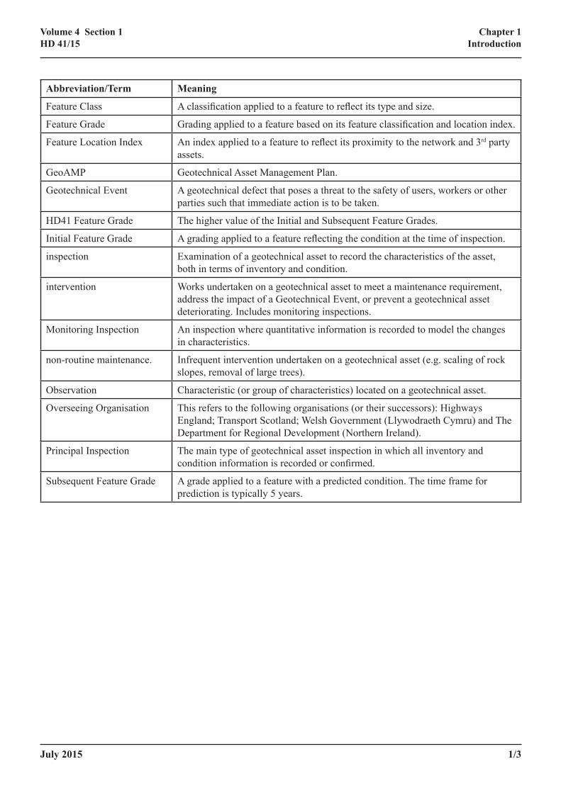
1.16 For the purpose of this Standard, the following definitions apply.
Abbreviation/Term Meaning
characteristic A property of a geotechnical asset.
defect A feature observed within a geotechnical asset that is assigned Class 1 in accordance with this standard.
Detailed Inspection Synonymous with Principal Inspection
Emergency Inspection An inspection undertaken in response to a Geotechnical Event, or other short term requirement.
Feature An observation that is assessed as requiring a feature grade.
July 2015 1/3
Chapter 1Introduction
Volume 4 Section 1HD 41/15
Abbreviation/Term Meaning
Feature Class A classification applied to a feature to reflect its type and size.
Feature Grade Grading applied to a feature based on its feature classification and location index.
Feature Location Index An index applied to a feature to reflect its proximity to the network and 3rd party assets.
GeoAMP Geotechnical Asset Management Plan.
Geotechnical Event A geotechnical defect that poses a threat to the safety of users, workers or other parties such that immediate action is to be taken.
HD41 Feature Grade The higher value of the Initial and Subsequent Feature Grades.
Initial Feature Grade A grading applied to a feature reflecting the condition at the time of inspection.
inspection Examination of a geotechnical asset to record the characteristics of the asset, both in terms of inventory and condition.
intervention Works undertaken on a geotechnical asset to meet a maintenance requirement, address the impact of a Geotechnical Event, or prevent a geotechnical asset deteriorating. Includes monitoring inspections.
Monitoring Inspection An inspection where quantitative information is recorded to model the changes in characteristics.
non-routine maintenance. Infrequent intervention undertaken on a geotechnical asset (e.g. scaling of rock slopes, removal of large trees).
Observation Characteristic (or group of characteristics) located on a geotechnical asset.
Overseeing Organisation This refers to the following organisations (or their successors): Highways England; Transport Scotland; Welsh Government (Llywodraeth Cymru) and The Department for Regional Development (Northern Ireland).
Principal Inspection The main type of geotechnical asset inspection in which all inventory and condition information is recorded or confirmed.
Subsequent Feature Grade A grade applied to a feature with a predicted condition. The time frame for prediction is typically 5 years.

1/4 July 2015
Chapter 1Introduction
Volume 4 Section 1HD 41/15

July 2015 2/1
Chapter 2Organisation and Roles
Volume 4 Section 1HD 41/15
2 ORGANISATION AND ROLESRoles
2.1 This document defines and refers to two key organisational roles:
(i) A Geotechnical Advisor (GA); responsible for overview of the asset performance and agreement of management strategy & plans.
(ii) A Geotechnical Maintenance Liaison Engineer (GMLE); responsible for operational management activities.
2.2 Typically the Geotechnical Advisor will represent the interests of the Overseeing Organisation, whilst the Geotechnical Maintenance Liaison Engineer will represent the organisation responsible for day-to-day management of the assets.
2.3 The organisation(s) responsible for the day-to-day management of the assets for the Overseeing Organisation will be defined by the particular contract requirements in place. Throughout this application document, the main organisation undertaking the activities is referred to as the service provider, irrespective of contractual arrangement.
2.4 The Geotechnical Maintenance Liaison Engineer should liaise directly with their respective Geotechnical Advisor.
Competencies and responsibilities
2.5 The GMLE shall be a chartered member of a relevant professional body and have a minimum of 5 years post chartered experience. The GMLE shall be able to demonstrate responsibility for the planning and execution of projects involving geotechnical design, construction and monitoring.
2.6 All personnel undertaking inspections shall have received training in the methods of inspection, recognition of geotechnical characteristics, assessment of Observations and grading of geotechnical features outlined in this application document.
2.7 At least one member of any inspection team shall have specialist experience of geotechnical inspection activities, and have proven and demonstrable experience of geotechnical engineering and site inspection.

2/2 July 2015
Chapter 2Organisation and Roles
Volume 4 Section 1HD 41/15
July 2015 3/1
Chapter 3Geotechnical Asset Management Plan
Volume 4 Section 1HD 41/15
3 GEOTECHNICAL ASSET MANAGEMENT PLAN3.1 A Geotechnical Asset Management Plan (GeoAMP) sets out how the geotechnical asset is to be managed for
a specific area or route. The GeoAMP is prepared by the service provider and details the forward programme of inspections and planned interventions. Forward planning activities within a GeoAMP shall be for a rolling five year period.
3.2 The service provider shall review the GeoAMP on an annual basis at a time agreed with the Overseeing Organisation.
3.3 The service provider shall submit the GeoAMP to the Overseeing Organisation for agreement.
Outline Contents
3.4 The GeoAMP shall include, as a minimum, details of the following:
(i) An outline of the geotechnical hazards that potentially affect the motorway and trunk road network.
(ii) An overview of the geotechnical asset, the number of assets, their length, and dates of last inspection.
(iii) An overview of the historic, current and predicted condition of the geotechnical asset.
(iv) A summary of the inspections, surveys (such as ground investigations) and monitoring carried out within the reporting period of the GeoAMP.
(v) A summary of Geotechnical Events that have occurred within the reporting period of the GeoAMP and their impact on the network.
(vi) A schedule of inspections and monitoring to be carried out.
(vii) Details of surveys (such as ground investigations).
(viii) A summary of the completed and proposed geotechnical works.
3.5 The GeoAMP shall record risk assessments for inspection and maintenance activities. The methods used shall be recorded. Risk assessment should include the following:
(i) hazards,
(ii) geotechnical asset information,
(iii) network criticality and
(iv) Proximity to other asset groups
Hazard appraisal
3.6 Hazards shall be identified and documented when considering geotechnical risk.
3/2 July 2015
Chapter 3Geotechnical Asset Management Plan
Volume 4 Section 1HD 41/15
3.7 The following types of hazard shall be considered:
(i) Natural hazards, relating to the natural environment in which the road is located. These hazards may be due to the behaviour of geological materials (for example voids due to dissolution of limestone, or soft/compressible ground due to the presence of alluvium) or the behaviour of natural slopes within the landscape (for example large-scale post-glacial slope instability).
(ii) Man-made hazards, which are not related to the imposition of the road network on the landscape. Examples include hazards relating to mining and quarrying, or construction of landfill.
(iii) Man-made hazards, which are related to the imposition of the road network on the landscape, for example over-steep slopes in earthworks.
3.8 The sources of information used for the hazard assessment shall be recorded.
3.9 Known mitigation measures shall be recorded. Examples of mitigation measures are slope drainage, capping of shafts or monitoring etc. Maintenance may be required to ensure the long-term performance of mitigation measures.
3.10 Hazards become defects as a result of triggers. Examples of triggers are severe weather events or defects related to other assets. Triggers shall be recorded against identified hazards or defects.
3.11 A prediction of the deterioration of the geotechnical asset should be made using the process in section 6, using Table 6-3 to derive Initial Feature Grades applied over specific time frames.
3.12 A deterioration assessment shall be supported by quantitative data and/or precedence information from elsewhere on the network, or from desk study review of other sources of information.
3.13 Detailed requirements for the GeoAMP are presented in Annex B.
July 2015 4/1
Chapter 4Asset Definition
Volume 4 Section 1HD 41/15
4 ASSET DEFINITIONGeotechnical asset types
4.1 The geotechnical asset of the Overseeing Organisation is divided into the following asset types:
(i) minor earthworks
(ii) major earthworks
4.2 Minor earthworks are those assets whose maximum vertical height within the longitudinal extent of the asset is less than 2.5m. Minor earthworks may comprise cuttings, embankments and at-grade sections.
4.3 Major earthworks are assets having a maximum vertical height within the longitudinal extent of the asset greater than or equal to 2.5m. If a major earthwork begins at-grade and extends to a vertical height equal to or greater than 2.5m within its longitudinal extent, then it is considered to be a major earthwork from its start point (at-grade) to its end point. Major earthworks may comprise cuttings, embankments and bunds.
The geotechnical asset Model
4.4 The geotechnical asset is modelled by linear lengths of network that usually follow the centreline of the carriageway. The network is not limited to the Overseeing Organisation’s pavement network because assets may start or finish beyond that network, due to assets extending onto sections of road managed by another highway authority.
Longitudinal definition of a geotechnical asset
4.5 The longitudinal extents (i.e. the start and end locations along the road length) of a geotechnical asset are defined by:
(i) points of zero height between geotechnical assets of different types (as defined below) or,
(ii) bridges and underpasses or,
(iii) service provider area boundaries or
(iv) significant changes in geology (as shown on the 1:50,000 BGS map, or observed) or
(v) significant changes in earthwork fill materials (as shown on as-built drawings, or observed).
Lateral definition of a geotechnical asset
4.6 The lateral extents of a geotechnical asset are defined by:
(i) the centre line of the carriageway immediately adjacent to the asset and/or
(ii) the ownership boundary of the Overseeing Organisation, typically marked by a fence line.
4.7 A section of the Overseeing Organisation network will typically have two geotechnical assets associated with it, one to each side of the carriageway centre line. In some cases, geotechnical assets may lie between carriageways (e.g. split carriageways and slip roads).

4/2 July 2015
Chapter 4Asset Definition
Volume 4 Section 1HD 41/15
July 2015 5/1
Chapter 5Inspections
Volume 4 Section 1HD 41/15
5 INSPECTIONS5.1 Inspection of a geotechnical asset has the following aims:
(i) To observe and record the presence, location and type of geotechnical assets that fall within the responsibility of the service provider.
(ii) To determine and record the key characteristics that describe each complete geotechnical asset; for example the geological material of which the asset is comprised, the geometry of the asset etc.
(iii) To observe and record the characteristics that relate to the condition of the geotechnical asset at the time of inspection.
(iv) To evaluate the geotechnical setting of the highway corridor within the landscape and the activities of adjacent landowners that may impact on the performance of the highway assets.
5.2 The length and number of geotechnical assets to be inspected may change for a number of reasons:
(i) Acquisition of assets into the responsibility of the Overseeing Organisation, for example through adoption of a local authority road.
(ii) Through the physical creation of new assets by construction of new road sections.
(iii) Through the physical creation of assets that are markedly different to an asset that they are enhancing, such that they can be considered new assets (for example junction re-modelling or significant widening of embankments).
(iv) Removal of assets from the responsibility of the Overseeing Organisation due to changes in administrative arrangements (such as de-trunking).
(v) Physical removal of the asset, such as in a junction re-modelling or similar.
Inspection types
5.3 Inspections types comprise the following:
(i) Detailed or Principal Inspections – these are the main type of inspection, providing inventory and condition data.
(ii) Monitoring Inspections – these are inspections undertaken as an intervention option to address risks posed by geotechnical assets.
(iii) Emergency inspections –inspections undertaken in response to a Geotechnical Event.
(iv) Inspections by non-geotechnical staff e.g. watchman inspections to recognise obvious geotechnical characteristics that are indicators of change.
5.4 Monitoring Inspections may be carried out as part of a schedule of Principal Inspections.

5/2 July 2015
Chapter 5Inspections
Volume 4 Section 1HD 41/15
Inspection methods
5.5 Inspections of assets shall be carried out such that the required information can be obtained.
5.6 Principal Inspections shall be carried out when the surface of the asset is visible, i.e. when the ground profile is not obscured by vegetation.
5.7 Where a geotechnical asset with exposed rock slopes is added to the inspection programme for the first time, an assessment of the slope shall be carried out using the Rock Slope Hazard Index (RSHI) system (Refs 3 & 4). Subsequent inspection requirements shall be determined using a risk-based approach.
5.8 Inspections of major earthworks should normally be close visual inspections. Methods of inspection such as remote inspection techniques e.g. from vehicle, or detailed aerial or terrestrial photography or scanning may be applicable.
Observations made during inspections
5.9 During inspections of geotechnical assets, characteristics of the assets shall be recorded over part or all of the asset length. These characteristics are recorded as Observations.
5.10 Characteristics shall be recorded in a formalised and repeatable manner.
5.11 Changes in the condition of the asset relative to the previous inspection shall be recorded.
5.12 Geotechnical hazards that could impact the road network, including those that are visible outside of the occupancy boundary shall be recorded, for example adjacent development, landfill operations, quarrying etc.
5.13 Non-geotechnical characteristics should not be recorded (for example presence of other assets), unless they indicate the presence of a hazard to the geotechnical asset (e.g. blocked drainage).
5.14 Quantitative information on particular observations within an asset shall be collected during Monitoring Inspections.
5.15 Photographs should be taken and/or sketches drawn, where their presence would assist in the understanding of the condition of the asset.
5.16 All Observations made during an inspection shall be assessed in accordance with the methods set out in Section 6.
5.17 Where a feature is assessed to be a defect (see Section 6) the following information relating to the feature shall be recorded:
(i) at least one photograph,
(ii) an annotated sketch and
(iii) quantitative measurements.
July 2015 5/3
Chapter 5Inspections
Volume 4 Section 1HD 41/15
Inspection frequency
5.18 The frequency of inspections shall be determined by the service provider using an assessment of risk posed by the asset to the road network, or other criteria as agreed with the Overseeing Organisation.
5.19 If insufficient information is available to undertake a risk assessment, or the Overseeing Organisation sets a specific frequency requirement, the stipulated requirement shall be the longest return frequency.
5.20 Risk assessments shall be carried out by the service provider. The results of the risk assessments and proposed inspection frequencies shall be agreed with the Overseeing Organisation. Guidance on the risk assessment process is provided in Annex A.
5.21 Principal Inspections of new assets shall be carried out as soon as practical after construction or transfer to the service provider.
5.22 The scheduled frequency of inspection shall be recorded against each asset in the asset management information system by the service provider.
5.23 It is recommended that inspection frequencies are generally set for a series of contiguous earthworks rather than isolated individual assets. This will simplify planning of inspections and limit the time required to be spent travelling between isolated parts of the network, interrupting the continuous asset inspection.
Geotechnical Events
5.24 A Geotechnical Event is a geotechnical defect that poses a threat to the safety of users, workers or other parties or critical assets, such that immediate action is to be taken. Examples include, but are not limited to:
(i) blockage of the carriageway by material that has moved as the result of slope failure of a cutting or debris flow as a result of erosion or,
(ii) subsidence of the carriageway due to collapse of a solution feature or mine shaft or
(iii) imminent subsidence of the carriageway due to scour of an embankment.
5.25 Immediate action following a Geotechnical Event may include one or more of the following:
(i) temporary signing or traffic management,
(ii) temporary barriers,
(iii) debris clearance,
(iv) temporary support,
(v) Monitoring Inspections
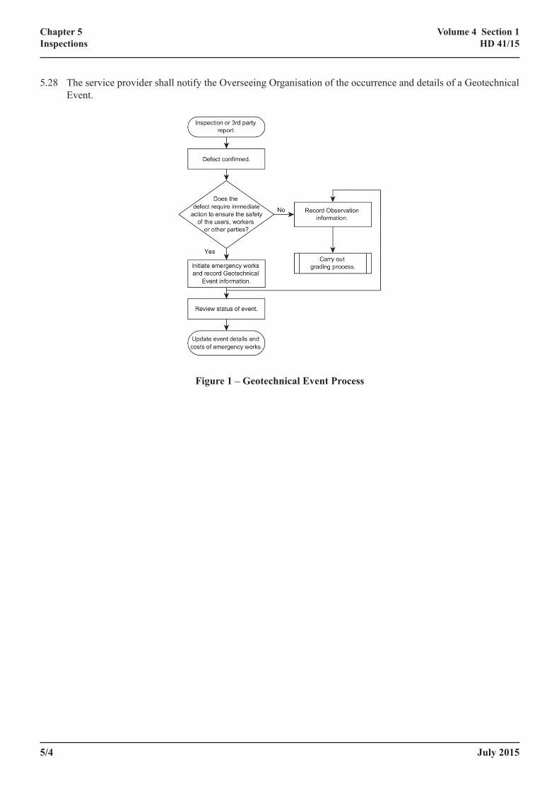
5.26 Following the report or discovery of a potential Geotechnical Event, the service provider shall carry out an Emergency Inspection and record the information required by the Overseeing Organisation. The process is shown in Figure 1.
5.27 Where the service provider determines that a Geotechnical Event has not occurred and the issue relates to another asset, the relevant asset manager should be informed.
5/4 July 2015
Chapter 5Inspections
Volume 4 Section 1HD 41/15
5.28 The service provider shall notify the Overseeing Organisation of the occurrence and details of a Geotechnical Event.
Figure 1 – Geotechnical Event Process
July 2015 6/1
Chapter 6Assessment
Volume 4 Section 1HD 41/15
6 ASSESSMENTAssessment and grading of features
6.1 Features are located observations within a geotechnical asset and recorded during an inspection that are assessed as requiring grading.
6.2 The grading of features provides an indicator of the relative condition of the asset at that point and is used for subsequent input into risk-based assessments, including inspections and interventions.
6.3 The service provider shall assess all observations and carry out grading when necessary.
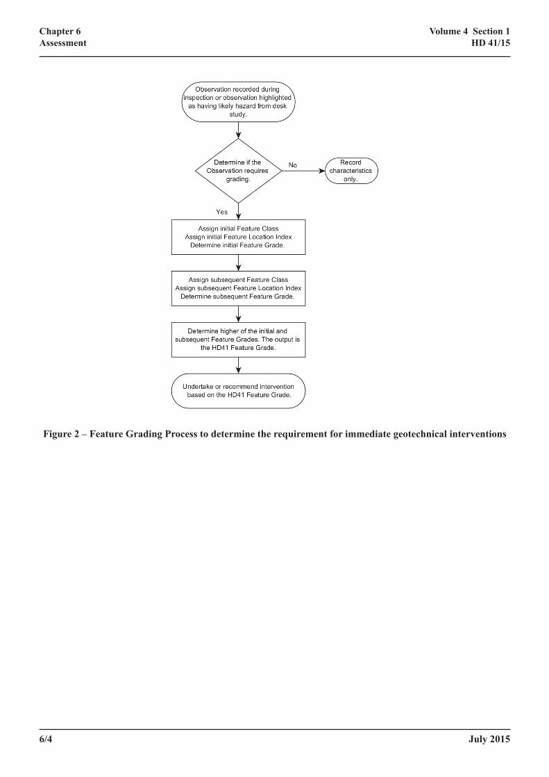
6.4 The grading process requires two inputs: (i) Feature Class and (ii) Feature Location Index. The process for Feature Grade Assessment is shown in Figure 2 and is described below.
6.5 The service provider should seek the advice of the Overseeing Organisation for organisation-specific guidance on the inspection and grading of features.
Assessment of Feature Class
6.6 For each feature identified during an inspection of a geotechnical asset, the service provider shall assign a Feature Class, based on the definitions given in Table 6-1.
6.7 The examples provided in Table 6-1 are intended to provide a repeatable assessment, however there will be exceptions to the examples and engineering judgement should be applied when determining Classes. Reasons for allocating Feature Class should be recorded if justification’s required.
6.8 The assessment of Feature Class must not consider the impact of the feature on the network or 3rd party property. It shall be confined to the size and type of feature only.
Class Description of feature Examples of features
Class 1 (visible defects)
1A Major defects. A slip greater than ½ height of a major earthwork.
A rock fall involving large boulder-size* blocks of rock or greater than 1m³ volume of rock debris.
1D Minor defects. Defects other than Major defects.
Class 2: (likely defects)
2 At Risk areas.
Assessment may be based on available information (maps, historical reports, behaviour of similar assets, etc.) and or visual inspection.
An asset overlying an area of mining activity where no mitigation measures were carried out during construction or where mitigation measures have deteriorated.
An area of sidelong natural or made ground subject to historical slope movement.
Animal burrows.
6/2 July 2015
Chapter 6Assessment
Volume 4 Section 1HD 41/15
Class Description of feature Examples of features
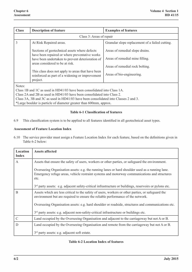
Class 3: Areas of repair
3 At Risk Repaired areas.
Sections of geotechnical assets where defects have been repaired or where preventative works have been undertaken to prevent deterioration of areas considered to be at risk.
This class does not apply to areas that have been reinforced as part of a widening or improvement project.
Granular slope replacement of a failed cutting.
Areas of remedial slope drains.
Areas of remedial mine filling.
Areas of remedial rock bolting.
Areas of bio-engineering.
Notes:Class 1B and 1C as used in HD41/03 have been consolidated into Class 1A.Class 2A and 2B as used in HD41/03 have been consolidated into Class 2.Class 3A, 3B and 3C as used in HD41/03 have been consolidated into Classes 2 and 3.*Large boulder is particle of diameter greater than 600mm, approx.
Table 6‑1 Classification of features
6.9 This classification system is to be applied to all features identified in all geotechnical asset types.
Assessment of Feature Location Index
6.10 The service provider must assign a Feature Location Index for each feature, based on the definitions given in Table 6-2 below:
Location Index
Assets affected
A Assets that ensure the safety of users, workers or other parties, or safeguard the environment.
Overseeing Organisation assets: e.g. the running lanes or hard shoulder used as a running lane. Emergency refuge areas, vehicle restraint systems and motorway communications and structures etc.
3rd party assets: e.g. adjacent safety-critical infrastructure or buildings, reservoirs or pylons etc.
B Assets which are less critical to the safety of users, workers or other parties, or safeguard the environment but are required to ensure the reliable performance of the network.
Overseeing Organisation assets: e.g. hard shoulder or roadside, structures and communications etc.
3rd party assets: e.g. adjacent non-safety-critical infrastructure or buildings etc.
C Land occupied by the Overseeing Organisation and adjacent to the carriageway but not A or B.
D Land occupied by the Overseeing Organisation and remote from the carriageway but not A or B.
3rd party assets: e.g. adjacent soft estate.
Table 6‑2 Location Index of features
July 2015 6/3
Chapter 6Assessment
Volume 4 Section 1HD 41/15
Assessment of Feature Grade
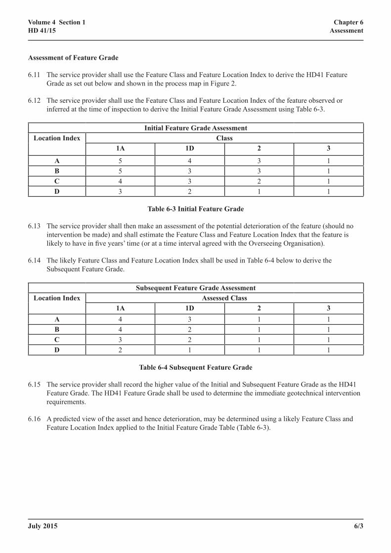
6.11 The service provider shall use the Feature Class and Feature Location Index to derive the HD41 Feature Grade as set out below and shown in the process map in Figure 2.
6.12 The service provider shall use the Feature Class and Feature Location Index of the feature observed or inferred at the time of inspection to derive the Initial Feature Grade Assessment using Table 6-3.
Initial Feature Grade AssessmentLocation Index Class
1A 1D 2 3
A 5 4 3 1B 5 3 3 1C 4 3 2 1D 3 2 1 1
Table 6‑3 Initial Feature Grade
6.13 The service provider shall then make an assessment of the potential deterioration of the feature (should no intervention be made) and shall estimate the Feature Class and Feature Location Index that the feature is likely to have in five years’ time (or at a time interval agreed with the Overseeing Organisation).
6.14 The likely Feature Class and Feature Location Index shall be used in Table 6-4 below to derive the Subsequent Feature Grade.
Subsequent Feature Grade AssessmentLocation Index Assessed Class
1A 1D 2 3A 4 3 1 1B 4 2 1 1C 3 2 1 1D 2 1 1 1
Table 6‑4 Subsequent Feature Grade
6.15 The service provider shall record the higher value of the Initial and Subsequent Feature Grade as the HD41 Feature Grade. The HD41 Feature Grade shall be used to determine the immediate geotechnical intervention requirements.
6.16 A predicted view of the asset and hence deterioration, may be determined using a likely Feature Class and Feature Location Index applied to the Initial Feature Grade Table (Table 6-3).
6/4 July 2015
Chapter 6Assessment
Volume 4 Section 1HD 41/15
Figure 2 – Feature Grading Process to determine the requirement for immediate geotechnical interventions

July 2015 7/1
Chapter 7Geotechnical Intervention and Scheme Prioritisation
Volume 4 Section 1HD 41/15
7 GEOTECHNICAL INTERVENTION AND SCHEME PRIORITISATION
Geotechnical Intervention
7.1 The service provider shall determine and record the required geotechnical intervention using the HD41 Feature Grade determined from the process described above.
7.2 Table 7-1 provides suggested geotechnical interventions for each Feature Grade. The highest priority intervention will be on those observations having Feature Grade 5. The lowest priority (Feature Grade 1) may result in no further action, other than continued inspection. Engineering judgement should be used and integrated asset management considerations should be made to determine the actual intervention method.
7.3 The method of assessment has been designed to be as objective as possible, to enable the process to be repeated. The Feature Grade must not be amended to suit the intervention. The interventions given in Table 7-1 are for guidance only, variations from the recommended interventions can be made with supporting justification.
HD41 Feature Grade Recommended Geotechnical intervention
5 Timely intervention to ensure safety should be undertaken.
Remedial intervention should be programmed typically within one year.
Assess inspection and monitoring requirements. Contingency planning required in preparation for any accelerated deterioration.
4 Remedial or preventative intervention should be programmed typically within 5 years. Assess inspection and monitoring requirements. Contingency planning required in preparation for any accelerated deterioration.
3 Remedial intervention not generally required within 5 years however remedial or preventative intervention may be programmed as part of other schemes.
2 Remedial intervention is not required, but preventative intervention may be required. Works do not need to be programmed and may be done as part of other schemes.
1 Remedial or preventative intervention is not required.
Notes: To be considered for all feature grades:
(i) Review Principal Inspection frequency and monitoring requirements.(ii) Consider linkages to other programmed interventions to optimise traffic management and
supervision.
Table 7‑1 Recommended geotechnical interventions
7.4 Many interventions on the geotechnical asset will involve construction or maintenance of associated assets, particularly the drainage asset. The planning of geotechnical interventions should be undertaken with due consideration of such cross-asset issues, and efficiencies should be sought where works can be phased to be undertaken on various asset types at the same time (for example through reduction of traffic management costs).

7/2 July 2015
Chapter 7Geotechnical Intervention and Scheme Prioritisation
Volume 4 Section 1HD 41/15
Schemes
7.5 Where interventions require the development of a scheme, the information gathered during inspections, monitoring and surveys shall be used to provide supporting evidence of the scheme requirement and prioritisation.
7.6 Schemes shall be developed in accordance with the processes required by the Overseeing Organisation. The geotechnical management of schemes shall be in accordance with HD22 (Ref 2).

July 2015 8/1
Chapter 8Information Requirements
Volume 4 Section 1HD 41/15
8 INFORMATION REQUIREMENTS8.1 Information is required to be recorded to support the following elements of geotechnical asset management:
(i) inspections,
(ii) geotechnical asset (inventory),
(iii) geotechnical asset (condition),
(iv) Geotechnical Events,
(v) schemes and
(vi) documents and records.
8.2 Information details are defined in Annex C.

8/2 July 2015
Chapter 8Information Requirements
Volume 4 Section 1HD 41/15

July 2015 9/1
Chapter 9References
Volume 4 Section 1HD 41/15
9 REFERENCESRef Number Reference Details
Normative
1 ISO 55000:2014 Asset management — Overview, principles and terminology.
2 HD22/08: Managing Geotechnical Risk (DMRB 4.1.2)
Informative
3 Rock slope risk assessment (Report PPR554). Transport Research Laboratory, 2011.
4 Rock engineering guides to good proactive: rock slope remediation and maintenance works (Report PPR555). Transport Research Laboratory, 2011.

9/2 July 2015
Chapter 9References
Volume 4 Section 1HD 41/15

July 2015 A/1
Annex AImplementation Requirements and Guidance
Volume 4 Section 1HD 41/15
ANNEX A – IMPLEMENTATION REQUIREMENTS AND GUIDANCE
A/2 July 2015
Annex AImplementation Requirements and Guidance
Volume 4 Section 1HD 41/15
Table of Contents
A‑12. Implementation ......................................................................................................................................A/3
A‑13. Layout of the annex ...............................................................................................................................A/3
A‑14. Organisation and Roles .........................................................................................................................A/3
A‑15. Geotechnical Asset Management Plan .................................................................................................A/3
A‑16. Asset definition .......................................................................................................................................A/5
A‑17. Inspections ..............................................................................................................................................A/5
A‑18. Example Principal Inspection Frequencies .........................................................................................A/7
A‑19. Monitoring Inspections .........................................................................................................................A/8
A‑20. Planning of Monitoring Inspections.....................................................................................................A/8
A‑21. Monitoring Techniques .........................................................................................................................A/8
A‑22. Reporting of Monitoring .......................................................................................................................A/9
A‑23. Geotechnical Events ..............................................................................................................................A/9
A‑24. Deterioration Assessment ......................................................................................................................A/10
July 2015 A/3
Annex AImplementation Requirements and Guidance
Volume 4 Section 1HD 41/15
A‑12. Implementation
A‑12.1 This Annex shall be used by service providers to comply with geotechnical asset management processes specific to the relevant Overseeing Organisation. It also provides additional advice and background to the text in HD41.
A‑12.2 The Overseeing Organisation is Highways England or its successor.
A‑13. Layout of the annex
A‑13.1 Where appropriate, the annex uses clause references (in parenthesis) to the main standard to make cross reference to the standard straightforward.
A‑14. Organisation and Roles
A‑14.1 (ref:cl. 2.4) Direct liaison between the Geotechnical Advisor and the Geotechnical Maintenance Liaison Engineer is encouraged. The Geotechnical Advisor should be able to impart considerable experience about past schemes and key hazards.
A‑15. Geotechnical Asset Management Plan
A‑15.1 (ref:cl. 3.0) Guidance for the preparation of the Geotechnical Asset Management Plan is provided in Annex B of the standard. The Overseeing Organisation provides a spreadsheet template for the tables. Searches and reports from the Overseeing Organisation’s asset information system are also available to generate the data required for the tables. The service provider should liaise with the Geotechnical Advisor for the latest guidance.
A‑15.2 (ref: cl. 3.6-3.10) Geotechnical Hazards
A‑15.3 The sources of information used for the hazard assessment typically include the following:
• specific hazard maps,
• old maps,
• current maps (OS, BGS),
• spatial data sets,
• geotechnical asset information and
• geotechnical report records.
A‑15.4 A list of some principal geotechnical hazards (or geohazards) which have the potential to affect highway geotechnical assets is presented below (Table A-1). The prevalence of some or all of these hazards may be appropriate for consideration in assessment of risk.
A‑15.5 Some areas may have been subject to previous preventative or remedial measures. These areas should be assessed to determine the residual risk.

A/4 July 2015
Annex AImplementation Requirements and Guidance
Volume 4 Section 1HD 41/15
A‑15.6 A significant amount of geohazard information can now be readily and rapidly obtained from various online sources and information providers, including the Overseeing Organisation’s asset information systems.
A‑15.7 Inspection frequencies and the factors influencing them should be reviewed on a regular basis such as annually prior to production of the GeoAMP.
Key Category Sub‑category Geotechnical Event resulting from combination of hazard and trigger
Natural hazards Dissolution features (inc cavities/voids)
Note: The presence and hazard posed by natural cavities may not always be related to surface water or groundwater
Subsidence Collapse
Soft or compressible ground Subsidence
Natural landslides (soil) Material on road
Natural landslides (rock) Material on road
Shrink/swell Subsidence/heave
Groundwater rise Slope instability (as landslides)
Surface flooding
Soil or groundwater chemistry Chemical damage (e.g. thaumasite), health and safety impacts (e.g. methane or radon)
Man-made hazards (non-road)
Abandoned mine workings and mine entries (coal and non-coal)
Note: Includes deneholes
Subsidence
Collapse
Surface instability
Backfilled opencast mines Subsidence
Current or future mining Subsidence
Quarries Rock face instability (old quarries)
Blast and vibration (active quarries)
Stability
Landfill sites Subsidence
Pollution (leachate & methane)
July 2015 A/5
Annex AImplementation Requirements and Guidance
Volume 4 Section 1HD 41/15
Key Category Sub‑category Geotechnical Event resulting from combination of hazard and trigger
Man-made hazards (road)
Engineered slopes of marginal stability (rock or soil)
Material on road or cracks/damage to assets
Defective or inappropriate drainage Slope instability
Surface flooding
Erosion
Dissolution of soluble rocks
Animal burrows
Note: These are classified as ‘man-made’ as they tend to affect man-made earthworks.
Slope instability
Loss of vegetation Slope instability
Erosion
Note: the hazards categorised in Columns 1 and 2 may require suitable triggers to cause the events listed in Column 3. Triggers may include natural occurrences such as heavy rainfall, high winds or earthquakes
Table A‑1 – Geotechnical hazard categories
A‑16. Asset definition
A‑16.1 (ref:cl. 4.1) The following terminology shall be used to describe the geotechnical asset for use by the Overseeing Organisation:
HD41 Term Overseeing Organisation Term
Minor Earthwork At-Grade
Major Earthwork Cutting, Embankment or Bund
A‑17. Inspections
A‑17.1 (ref: cl. 5.18) The frequency of inspections should be based on assessment of the risk posed to the network, 3rd party assets, users, workers or others by deterioration of the asset. Typically the higher this risk, the greater the appropriate frequency of inspection. The risk assessment should be based on considerations of asset Feature Grades, amount and types of hazards, likelihood of triggers and criticality of asset locations.
A‑17.2 Inspection frequencies may vary from low frequencies, possibly with a return frequency between 6 and 10 years to high frequencies, possibly with more than one inspection a year. In the case of high frequency inspections these may be more suited to inspection of individual sites under a monitoring programme than to high frequency Principal Inspections. A framework for the assessment of appropriate inspection frequencies is presented in Figure A-1 below.
A/6 July 2015
Annex AImplementation Requirements and Guidance
Volume 4 Section 1HD 41/15
Figure A‑1 – Example framework for the assessment of inspection frequency
A‑17.3 This framework considers the interaction of the health of the asset and the criticality of the network. The health of the asset can be determined from the current and predicted Feature Grade. The predicted Feature Grade considers the nature of the hazards and the likelihood of defects arising from the hazard. The criticality of the network should also be considered over time, e.g. the construction of Smart Motorway, major maintenance and renewals schemes.
A‑17.4 The process and framework for risk assessment is not mandated. The subject of risk assessment is a developing aspect of geotechnical asset management. Prior to carrying out a risk assessment the service provider should contact the Overseeing Organisation to determine the latest guidance.
A‑17.5 The following inspection frequencies should be used, dependent on the risk level:
• 6 to 10 year return frequency or,
• 2 to 5 year return frequency or,
July 2015 A/7
Annex AImplementation Requirements and Guidance
Volume 4 Section 1HD 41/15
• 6 months to 1 year return frequency or
• Less than 6 months return frequency.
A‑18. Example Principal Inspection Frequencies
A‑18.1 The following paragraphs give examples of how suitable Principal Inspection frequencies might be assigned.
(i) Principal Inspection Frequency Example One
A 6.5km long stretch of single carriageway trunk road forms the principal link between the motorway network and a major city. The road follows a historical route along a valley side. Periglacial conditions caused the development of a mantle of foundered strata through which the road has been formed, generally on sidelong ground. Several major defects have previously occurred both upslope and downslope of the road and have necessitated the construction of deep bored pile walls as remedial measures. Ongoing deterioration of existing minor and major defects has also been recorded.
Therouteexperienceshighvolumesofcommutertrafficandassociatedcongestion.Thealignmentfeaturesseveral tight bends with limited line of sight.
OnthisbasisthePrincipalInspectionfrequencyforthisroutehasbeenincreasedfromafiveyeartoaoneyear interval. The major defects are subject to Monitoring Inspections at 6 monthly intervals and trigger levels have been set to provide early warning of imminent Geotechnical Events. Associated remedial actions are included in the renewals programme (via the GeoAMP).
(ii) Principal Inspection Frequency Example Two
A 14km long stretch of motorway forms a key route to a major airport. The majority of the route is supported by and formed through earthworks within overconsolidated clay deposits. Several major defects have previously occurred within these earthworks, generally considered to be associated with oversteep slope construction and the presence of over-the-edge drainage. Embankment slopes in the area have been subject to regular repairs. A large number of minor defects are currently recorded indicating that major defects are likely unless preventative action is taken.
The available diversion routes pass through the centre of three large towns. Whilst the motorway itself is generally of three-lane construction in both directions, it is close to capacity and is subject to heavy congestion at peak times.
OnthisbasisthePrincipalInspectionreturnfrequencyforthisroutehasbeensetatafiveyearinterval.Monitoring Inspections are scheduled at annual intervals for those minor defects that are likely to become major defects. Associated preventative actions are included in the renewals programme (via the GeoAMP).
(iii) Principal Inspection Frequency Example Three
An 80km stretch of predominantly dual carriageway trunk road passes through and over earthworks formed in chalk deposits. The road was constructed to recent standards.
Nosignificantsloperepairsorexistingmajororminordefectshavebeenidentifiedalongtheroute.Howeverravelling of some of the steeper exposed chalk cuttings is ongoing and mitigated using rock capture netting. Whilst some dissolution features are expected to be present within the chalk, overlying drift deposits are generally limited in extent and the risk of Geotechnical Events associated with these features is considered to be negligible.
A/8 July 2015
Annex AImplementation Requirements and Guidance
Volume 4 Section 1HD 41/15
OnthisbasisthePrincipalInspectionreturnfrequencyfortheroutehasbeendecreasedfromafiveyeartoaneightyearinterval.MaintenanceofrocknettingisrecordedagainstspecificassetsandhighlightedintheGeoAMP.
A‑19. Monitoring Inspections
A‑19.1 (ref cl.5.3ii) Monitoring is integral to the overall inspection programme and should form a key part of the long term risk management of the geotechnical asset. Monitoring Inspections can take a variety of forms, but independent of the methods employed it is important to ensure that the purpose of monitoring is clear and that trigger levels and actions required following the exceedance of such trigger levels are defined.
A‑19.2 The collection and use of quantitative information is useful as evidence for scheme appraisal and as input into predictive modelling of asset deterioration.
A‑20. Planning of Monitoring Inspections
A‑20.1 It is important to be clear regarding what is being monitored and how and when that monitoring is being undertaken. Records should be kept of sites subject to monitoring, particularly including the details described below.
• What is being monitored, and how the monitoring is being carried out.
• How often monitoring is to be undertaken and at what times of year (for example, following winter storms).
• Detailed descriptions of the defects being proposed for monitoring, any historical monitoring results that are available, and a summary of the defect/repair history of the Asset.
• Identified trigger levels and the actions to be undertaken if trigger levels are reached or exceeded (including emergency response procedures).
• What allowance there is for increased monitoring in times of increased risk (e.g. extreme weather events).
• What the communication routes are for reporting of monitoring results and which individuals are responsible for communication.
A‑20.2 Initial recommendations of monitoring regimes for individual sites should be recorded through an entry in the asset information system at the appropriate stage of consideration of a defect. For example, where a defect of feature grade 4 has been identified during a Principal Inspection, but the site investigation is pending or deferred, then monitoring of the defect may be carried out to understand the rate of deterioration. The need for monitoring should be reviewed regularly with the Overseeing Organisation to ensure that it is still relevant and that intervals of monitoring are still appropriate.
A‑21. Monitoring Techniques
A‑21.1 A variety of techniques are available for the monitoring of geotechnical features and monitoring at a given site is likely to include one or a combination of such techniques. The appropriate combination of techniques will depend on a number of factors including the nature and extent of the defect, available budget, access constraints and expected rate of deterioration. Techniques used may include one or more of the following:
• Visual inspection.

July 2015 A/9
Annex AImplementation Requirements and Guidance
Volume 4 Section 1HD 41/15
• Measurements between pegs installed at the surface.
• Direct measurements of features at fixed locations, e.g. tension crack width and length; backscarp height, or tilt of surfaces, safety furniture or structures.
• Photographic records taken of the same aspect on repeated occasions.
• Subsurface instrumentation including piezometers, inclinometers and extensometers. These may be automated or manually read.
• Remote sensing techniques such as LiDAR and high resolution aerial photography, including change detection analyses.
• Tell-tale instrumentation.
A‑21.2 It is important that the techniques used allow data to be collected that will illustrate trends of deterioration where these are present. Readings should be repeatable and the accuracy and repeatability of instrumentation should be assessed. Careful consideration should be given to the installation of monitoring equipment; for example, inclinometers should be installed to sufficient depth to be anchored below likely failure surfaces and surface monitoring pegs should be sufficiently robust that they are not readily disturbed by wildlife.
A‑22. Reporting of Monitoring
A‑22.1 The GeoAMP will summarise all monitoring in place, or known to be commencing, at the time of preparation, however, as the GeoAMP is an annually submitted document, there may still be a need for additional monitoring reports to be submitted including the details described above. Reporting requirements for monitoring should also be agreed locally with the Overseeing Organisation.
A‑23. Geotechnical Events
A‑23.1 (ref: cl. 5.24) Geotechnical Events are defined as occurrences of geotechnical defects that pose a threat to the safety of users, workers or other parties such that immediate action is to be taken. Such immediate action is required to be taken to mitigate the defect’s impact, through for example the installation of temporary safety barrier or implementation of traffic management. Geotechnical Events supersede and expand on the role of geotechnical maintenance forms in notifying the Overseeing Organisation of such occurrences.
A‑23.2 A Geotechnical Event may need to be recorded as an incident to comply with contractual obligations.
A‑23.3 A Geotechnical Event includes details of:
• Reporting of the event to and by the service provider
• Effects on the running of the carriageway, for example traffic management and closures
• Elements of highway infrastructure impacted by the event
A‑23.4 Additionally, a status is allocated to a Geotechnical Event. This may be Imminent, Ongoing or Cleared. The majority of events will have an Ongoing or Cleared status. However it is recognised that in some cases emergency measures will be taken in the case of defects which have not yet impacted adversely on the network, but which are expected to in the imminent future. An example may be where a backscarp
A/10 July 2015
Annex AImplementation Requirements and Guidance
Volume 4 Section 1HD 41/15
is rapidly retreating towards the safety barrier during a period of wet weather and would be expected to undermine the barrier if the period of current weather conditions continues. The status would be required to be changed accordingly once the situation has either developed or stabilised.
A‑23.5 The Geotechnical Event may also incur costs associated with activities such as:
• emergency works
• site investigation
• reporting, and
• construction of an eventual solution.
A‑23.6 Assessment
A‑23.7 (ref: Table 6-1) Class 2 Features are those assessed to be likely to deteriorate to a Feature Class 1 defect. This may be done as part of a desk study process when preparing the GeoAMP using a hazard assessment together with an understanding of triggers.
A‑24. Deterioration Assessment
A‑24.1 The following sources of information may be used to inform assessments:
• Infrastructure embankments, condition appraisal and remedial treatment (C592). CIRIA, 2003
• Infrastructure cuttings, condition appraisal and remedial treatment (C591). CIRIA, 2003
• Transport Research Laboratory publications,
• quantitative data obtained through regular monitoring inspections,
• slope stability modelling,
• national/international experience,
• locations prone to flood risk as determined from EA Flood Risk models and
• engineering judgement and local experience. Advice should be sought from the Overseeing Organisation.
A‑24.2 Geotechnical Intervention and scheme prioritisation
A‑24.3 (Ref: cl 7.5) Good quality (complete and accurate) geotechnical asset information obtained during Principal Inspections, and Monitoring Inspections is of key importance in the development of a forward programme of proposed geotechnical maintenance activities. Supporting evidence such as sketches and photographs are helpful to communicate the nature of the feature.
A‑24.4 The objective data collected during Monitoring Inspections is especially useful to demonstrate deterioration and the requirement for intervention.

July 2015 B/1
Annex BGeotechnical Asset Management Plan – Guidance
Volume 4 Section 1HD 41/15
ANNEX B – GEOTECHNICAL ASSET MANAGEMENT PLAN – GUIDANCE

B/2 July 2015
Annex BGeotechnical Asset Management Plan – Guidance
Volume 4 Section 1HD 41/15
CONTENTS PAGE
B‑1. Introduction ...........................................................................................................................................B/4
B‑2. Implementation ......................................................................................................................................B/4
B‑3. Document structure and confidentiality ..............................................................................................B/4
B‑4. Document compilation ..........................................................................................................................B/4
B‑5. Document submission ............................................................................................................................B/5
GeoAMP Requirements: PART ONE .................................................................................................................B/6
B‑6. Contents ..................................................................................................................................................B/6
B‑7. Summary ................................................................................................................................................B/7
B‑8. Introduction ...........................................................................................................................................B/7
B‑9. Geotechnical setting...............................................................................................................................B/7
B‑10. Recent activity and developments ........................................................................................................B/7
B‑11. Maintenance activity over the previous year ......................................................................................B/8
B‑12. Other geotechnical developments ........................................................................................................B/9
B‑13. Asset data ...............................................................................................................................................B/9
B‑14. Discussion of asset classification ...........................................................................................................B/12
B‑15. Risk based approach .............................................................................................................................B/12
B‑16. Hazards and triggers .............................................................................................................................B/12
B‑17. Potential impacts ...................................................................................................................................B/12
B‑18. Risk Assessments ...................................................................................................................................B/13
B‑19. Proposed programme ............................................................................................................................B/13
B‑20. Improving, replacing and building new assets ....................................................................................B/14
GeoAMP Requirements: PART TWO ................................................................................................................B/15
B‑21. Contents ..................................................................................................................................................B/15
B‑22. Principal Inspections and Monitoring Inspections over the previous year ......................................B/15
B‑23. Principal Inspections and Monitoring Inspections predicted for the next 5 years ..........................B/15

July 2015 B/3
Annex BGeotechnical Asset Management Plan – Guidance
Volume 4 Section 1HD 41/15
B‑24. Maintenance and renewal activity over the previous year ................................................................B/16
B‑25. Maintenance and renewal activity predicted for the next 5 years. ...................................................B/17
B‑26. Lessons learned / good practice ............................................................................................................B/18
B/4 July 2015
Annex BGeotechnical Asset Management Plan – Guidance
Volume 4 Section 1HD 41/15
B‑1. Introduction
B‑1.1 The following document details the requirements for the Geotechnical Asset Management Plan (GeoAMP). Note that the GeoAMP was previously referred to as the ‘GAMP’. The change in acronym was introduced to remove possible confusion with the General Asbestos Management Plan (GAMP).
B‑2. Implementation
B‑2.1 This Annex shall be used by service providers to comply with the GeoAMP requirements specific to the relevant Overseeing Organisation. It also provides additional advice and background to the text in HD41.
B‑2.2 The Overseeing Organisation is Highways England or its successor.
B‑3. Document structure and confidentiality
B‑3.1 The GeoAMP has been divided into two parts in order to separate commercially sensitive information from the geotechnical asset reporting, assessment and planning of future management activities.
B‑3.2 Part One of the GeoAMP presents background information, details of works, inspections and surveys completed over the previous year, a summary of significant hazards affecting the geotechnical asset and discussion of potential impacts. It presents the risk based approach used in the planning and prioritisation of inspection, monitoring and renewals schemes.
B‑3.3 Information included in Part Two of the GeoAMP includes details of outturn costs of key geotechnical activities over the previous year and predicted costs of future geotechnical activities. It also describes lessons learned over the previous year and recommendations of good practice.
B‑3.4 Information included in Part Two of the GeoAMP, and in any associated spreadsheets will be treated as commercially sensitive and in confidence. It shall have limited access, restricted to the respective service provider and Overseeing Organisation staff until the termination of the contract with the service provider or as defined otherwise in that contract. Information in Part One of the GeoAMP shall have no access restrictions placed on it.
B‑3.5 Part 2 of the GeoAMP must be marked OFFICIAL – SENSITIVE COMMERCIAL in capital letters at the top and bottom of each page.
B‑4. Document compilation
B‑4.1 Parts 1 and 2 of the GeoAMP should be compiled as separate documents, such that they have their own document revision and contents pages. The titles of the documents should be the same other than the part numbers and they should reference each other.
B‑4.2 Where previous GeoAMPs have been submitted within the current service provider contract, reference should be made to previous GeoAMP submissions for generic information. This does not need to be repeated in each GeoAMP unless the information has changed.
B‑4.3 The service provider should liaise with the Overseeing Organisation prior to compiling the GeoAMP to obtain the latest version of electronic file templates such as spreadsheet tables.
B‑4.4 Where tables are included in Part 2 of the GeoAMP they shall be consistent with the format of the tables and ordering of the information presented in Part 1.
July 2015 B/5
Annex BGeotechnical Asset Management Plan – Guidance
Volume 4 Section 1HD 41/15
B‑4.5 The information included in the GeoAMP should be based on the current network area. The potential impact of known planned area boundary changes should be recorded and any impact stated.
B‑5. Document submission
B‑5.1 The metadata for GeoAMP Parts One and Two shall be recorded on the Overseeing Organisation’s geotechnical records management system. Part One shall be issued to the Overseeing Organisation for upload onto the records management system. Part Two shall be issued to the Overseeing Organisation for storage on their internal records management system.

B/6 July 2015
Annex BGeotechnical Asset Management Plan – Guidance
Volume 4 Section 1HD 41/15
GeoAMP Requirements: PART ONE
B‑6. Suggested Contents
• Summary
• Introduction
• Geotechnical setting
• Recent Activity and Developments
• Maintenance activity over the previous year
• Inspections and monitoring
• Maintenance works
• Other maintenance activity
• Other geotechnical developments
• Asset data
• Asset data quality and currency
• Asset data summary
• Discussion of asset classification
• Risk based approach
• Hazards and triggers
• Potential impacts
• Risk Assessments
• Proposed programme
• Improving, replacing and building new assets

July 2015 B/7
Annex BGeotechnical Asset Management Plan – Guidance
Volume 4 Section 1HD 41/15
B‑7. Summary
B‑7.1 Succinctly summarise the content of the report; describe any fundamental changes in contract; note any significant geotechnical works completed since production of the last GeoAMP and those scheduled within the next 12 months; highlight significant events that directly affected the Feature Grade of the geotechnical asset since the previous report i.e. landslides, flooding, subsidence.
B‑7.2 Include current observation lengths to which each Feature Grade has been assigned, both in length in kilometres and as a percentage of the total earthwork length in the maintenance area.
B‑7.3 Provide a summary table of Principal Inspections, Monitoring Inspections, studies, ground investigations, design input & construct works for the forthcoming 5 year period.
B‑8. Introduction
• form of maintenance contract (with start and end dates),
• name of service provider,
• names of Managing Agent Geotechnical Liaison Engineer and Geotechnical Advisor,
• any changes to area boundaries and what affect the changes have on the number and type of assets.
B‑9. Geotechnical setting
• topography,
• hydrology,
• geology,
• geomorphological features,
• key man-made ground related features and,
• motorway and trunk road network.
B‑9.1 Highlight key features affecting or having the potential to affect the geotechnical asset. Whilst this section may not require repetition in each version of the GeoAMP, any significant changes since production of the previous GeoAMP should be described. These may have occurred, for example, as a result of changing of network boundaries or improved/revised knowledge.
B‑9.2 Include suitable maps (min A3 size) presenting these features within an Appendix to the GeoAMP.
B‑10. Recent activity and developments
B‑10.1 Provide a brief summary description of geotechnical developments, maintenance activities and Geotechnical Events over the previous year.
B/8 July 2015
Annex BGeotechnical Asset Management Plan – Guidance
Volume 4 Section 1HD 41/15
B‑11. Maintenance activity over the previous year
Inspections and monitoring
B‑11.1 Provide a list of inspections completed compared with those intended based on the previous GeoAMP. Route lengths inspected are to be quoted for comparison.
B‑11.2 Describe monitoring activities undertaken to assess the deterioration of identified defects or assets considered to be ‘at risk’.
Maintenance works
B‑11.3 Provide details of works completed and the impact of the works to the network. The information required to be included is listed below.
Works completed – Part One:
• Year
• Project or site title
• Geotechnical defect IDs
• Road, e.g. Motorway or All Purpose Trunk Road (APTR)
• Type, e.g. Embankment or Cutting
• Project Size, e.g. Small, Major, Hybrid etc.
• Work type
• Whether this was the principal work type.
• Description of ‘other’ where selected as the work type
• Approximate length of works (m)
• Approximate vertical height of works / retained height (m)
• Quantity of the standard unit for this work type
• Comments including VM score if known.
B‑11.4 Renewals projects included in this table should be those which have geotechnical lead, or which are geotechnical elements of a ‘hybrid’ scheme. Major Projects must not be included. Costs listed should include all elements that contribute to a geotechnically led scheme, not just the input of the geotechnical team. For example, if a slope repair includes elements or drainage, safety fence reinstatement etc., these should be included in the costs provided.
B‑11.5 Include a list of all geotechnical works completed in the current service provider’s contract in an Appendix to the GeoAMP.
July 2015 B/9
Annex BGeotechnical Asset Management Plan – Guidance
Volume 4 Section 1HD 41/15
Other maintenance activity
B‑11.6 Describe any other geotechnical maintenance activities undertaken including production of route or network wide studies and maintenance strategy reviews. Key conclusions of such studies and reviews should be summarised.
B‑12. Other geotechnical developments
B‑12.1 Provide a summary of any significant events, occurrences or developments affecting the network over the previous year not directly related to geotechnical maintenance activity. This may include:
• changes to the network extents,
• significant natural events e.g. severe weather, flooding,
• construction of other assets that have affected the geotechnical asset,
• identification of any other specific hazards with the potential to affect the geotechnical asset, for example works outside the occupancy boundary.
B‑13. Asset data
Asset data quality and currency
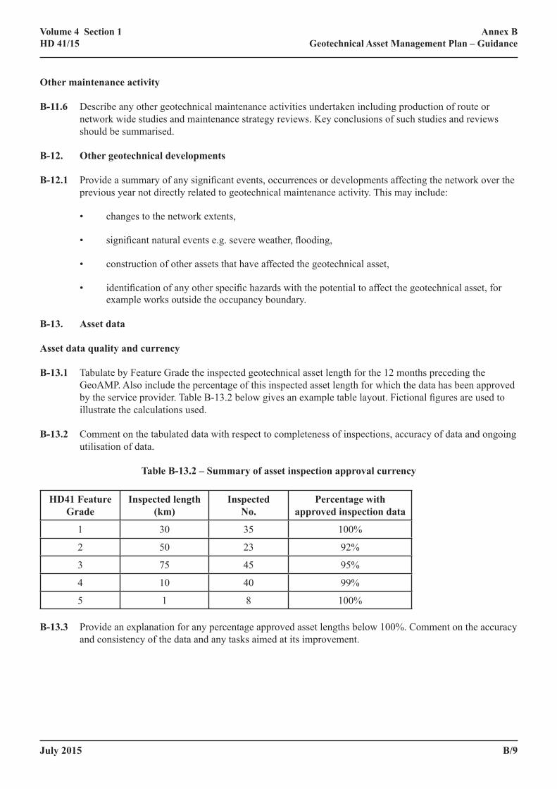
B‑13.1 Tabulate by Feature Grade the inspected geotechnical asset length for the 12 months preceding the GeoAMP. Also include the percentage of this inspected asset length for which the data has been approved by the service provider. Table B-13.2 below gives an example table layout. Fictional figures are used to illustrate the calculations used.
B‑13.2 Comment on the tabulated data with respect to completeness of inspections, accuracy of data and ongoing utilisation of data.
Table B‑13.2 – Summary of asset inspection approval currency
HD41 Feature Grade
Inspected length (km)
Inspected No.
Percentage with approved inspection data
1 30 35 100%
2 50 23 92%
3 75 45 95%
4 10 40 99%
5 1 8 100%
B‑13.3 Provide an explanation for any percentage approved asset lengths below 100%. Comment on the accuracy and consistency of the data and any tasks aimed at its improvement.
B/10 July 2015
Annex BGeotechnical Asset Management Plan – Guidance
Volume 4 Section 1HD 41/15
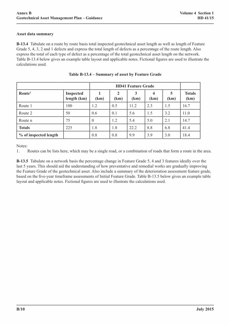
Asset data summary
B‑13.4 Tabulate on a route by route basis total inspected geotechnical asset length as well as length of Feature Grade 5, 4, 3, 2 and 1 defects and express the total length of defects as a percentage of the route length. Also express the total of each type of defect as a percentage of the total geotechnical asset length on the network. Table B-13.4 below gives an example table layout and applicable notes. Fictional figures are used to illustrate the calculations used.
Table B‑13.4 – Summary of asset by Feature Grade
HD41 Feature Grade
Route1 Inspected length (km)
1(km)
2(km)
3(km)
4(km)
5(km)
Totals(km)
Route 1 100 1.2 0.5 11.2 2.3 1.5 16.7
Route 2 50 0.6 0.1 5.6 1.5 3.2 11.0
Route n 75 0 1.2 5.4 5.0 2.1 14.7
Totals 225 1.8 1.8 22.2 8.8 6.8 41.4
% of inspected length 0.8 0.8 9.9 3.9 3.0 18.4
Notes:1. Routes can be lists here, which may be a single road, or a combination of roads that form a route in the area.
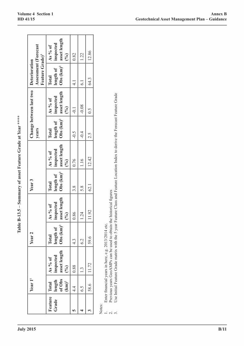
B‑13.5 Tabulate on a network basis the percentage change in Feature Grade 5, 4 and 3 features ideally over the last 5 years. This should aid the understanding of how preventative and remedial works are gradually improving the Feature Grade of the geotechnical asset. Also include a summary of the deterioration assessment feature grade, based on the five-year timeframe assessments of Initial Feature Grade. Table B-13.5 below gives an example table layout and applicable notes. Fictional figures are used to illustrate the calculations used.
July 2015 B/11
Annex BGeotechnical Asset Management Plan – Guidance
Volume 4 Section 1HD 41/15
Tabl
e B
‑13.
5 –
Sum
mar
y of
ass
et F
eatu
re G
rade
at Y
ear
****
Year
11
Year
2Ye
ar 3
Cha
nge
betw
een
last
two
year
sD
eter
iora
tion
Ass
essm
ent (
Fore
cast
Fe
atur
e G
rade
)3
Feat
ure
Gra
deTo
tal
leng
th
of O
bs
(km
)2
As %
of
insp
ecte
d as
set l
engt
h (%
)
Tota
l le
ngth
of
Obs
(km
)2
As %
of
insp
ecte
d as
set l
engt
h (%
)
Tota
l le
ngth
of
Obs
(km
)2
As %
of
insp
ecte
d as
set l
engt
h (%
)
Tota
l le
ngth
of
Obs
(km
)2
As %
of
insp
ecte
d as
set l
engt
h (%
)
Tota
l le
ngth
of
Obs
(km
)2
As %
of
insp
ecte
d as
set l
engt
h (%
)
54.
40.
884.
30.
863.
80.
76-0
.5-0
.14.
10.
82
46.
51.
36.
21.
245.
81.
16-0
.4-0
.08
6.1
1.22
358
.611
.72
59.6
11.9
262
.112
.42
2.5
0.5
64.3
12.8
6
Not
es:
1.
Ente
r fina
ncia
l yea
rs in
her
e, e
.g. 2
013/
2014
etc
.2.
Pr
evio
us y
ears
Geo
AM
Ps c
an b
e us
ed to
obt
ain
the
hist
oric
al fi
gure
s3.
U
se In
itial
Fea
ture
Gra
de m
atrix
with
the
5 ye
ar F
eatu
re C
lass
and
Fea
ture
Loc
atio
n In
dex
to d
eriv
e th
e Fo
reca
st F
eatu
re G
rade
B/12 July 2015
Annex BGeotechnical Asset Management Plan – Guidance
Volume 4 Section 1HD 41/15
B‑14. Discussion of asset classification
B‑14.1 Include discussion of the asset data, including comments on:
• Any detrimental changes e.g. increase in the percentage of defects, and known or likely causes of these changes.
• Geographical areas of note, for example those with high concentrations of defects or notably low percentages of defects. Reasons for such concentrations where known.
• Interpretation of the At Risk and minor defect data, its accuracy and how this may possibly affect future inspection strategies. Basis for assignment of At Risk zones.
B‑15. Risk based approach
B‑15.1 Describe the risk based approach used in the development of the forward programmes of:
• inspections,
• monitoring and maintenance,
• scheme development.
B‑15.2 Describe the methods used in the identification of hazards, triggers and potential impacts.
B‑15.3 Set out the forward programme and describe how the risk-based approach has been used to derive the programme.
B‑16. Hazards and triggers
B‑16.1 Describe hazards with the potential to affect the geotechnical asset which have been considered in the risk based approach adopted. Describe data and studies that have been used to identify the prevalence of these hazards. Hazards should not be restricted to those directly related to slopes; consideration should be given to other hazards such as natural and man-made cavities and weaker deposits beneath embankments. Consideration should also be given to hazards lying outside of the occupancy boundary.
B‑16.2 Compile a hazard map of the area if sufficient information is available. Make reference to any specific route studies previously completed.
B‑16.3 Discuss the triggers associated with these hazards which could result in the development of a defect. For example heavy rainfall may trigger defects in desiccated high plasticity clay earthworks.
B‑17. Potential impacts
B‑17.1 Describe how the potential impacts have been assessed for defects associated with these hazards and triggers, especially where there are concentrations of Feature Grade 4 or 5 defects along a route that may lead to Geotechnical Events. These may include route criticality, traffic flow, hard shoulder running etc. Include comments on:
• cross-asset impacts (for example impacts on pavement, cabling and drainage)
• lane closures
July 2015 B/13
Annex BGeotechnical Asset Management Plan – Guidance
Volume 4 Section 1HD 41/15
• diversions
• disruption to business
• requirements for traffic management, and
• safety implications.
B‑18. Risk Assessments
B‑18.1 Present the results of the risk assessments.
B‑19. Proposed programme
B‑19.1 Present the programme for the whole cycle of geotechnical maintenance from Principal Inspection to planned construction of any renewals schemes. Include any key financial dates and any key dates of relevance from the Traffic Operations Programming Guide (TOPG).
• Programme of Principal Inspections and monitoring
• Programme of studies and ground investigations
• Programme of design activities
• Programme of construction activities.
B‑19.2 Provide the programme of inspections for the forthcoming 5 years including details of route, year of inspection and earthwork length to be inspected. This information should be presented in a table.
B‑19.3 Provide a summary table including the information listed below.
Principal Inspection and Monitoring Inspection programme – Part One:
• Financial Year
• Road name(s) or site name
• Type, e.g. Principal Inspection (Repeat), Monitoring Inspection
• Type Group, e.g. Inspection
• Number of man days required
• Approximate length (km)
• Comments.
B‑19.4 Provide a plan of the area showing the locations of the inspections and monitoring for the forthcoming year.
B/14 July 2015
Annex BGeotechnical Asset Management Plan – Guidance
Volume 4 Section 1HD 41/15
B‑20. Improving, replacing and building new assets
B‑20.1 Provide a summary table of schemes to be undertaken in the next 5 years. The information required to be included is listed below.
• Year
• Scheme title
• Geotechnical defect ID’s if known
• Road, e.g. Motorway or All Purpose Trunk Road (APTR)
• Type, e.g. Embankment or Cutting
• Project Size, e.g. Small, Major, Hybrid etc
• Proposed work type
• Whether this is the principal work type
• Approximate length of works (m)
• Approximate vertical height of works / retained height (m)
• Quantity of the standard unit for this work type
• Comments including prioritisation
July 2015 B/15
Annex BGeotechnical Asset Management Plan – Guidance
Volume 4 Section 1HD 41/15
GeoAMP Requirements: PART TWO
B‑21. Suggested Contents
• Principal Inspections and Monitoring Inspections over the previous year
• Principal Inspections and Monitoring Inspections predicted for the next 5 years
• Maintenance and renewal activity over the previous year
• Maintenance and renewal activity predicted for the next 5 years
• Lessons learned / good practice
B‑22. Principal Inspections and Monitoring Inspections over the previous year
B‑22.1 Present a table of inspections completed in the last year. Include the information regarding outturn costs as listed below:
Principal Inspection and Monitoring Inspection programme – Part Two:
• Financial Year
• Road name(s) or site name
• Type, e.g. Principal Inspection (Repeat), Monitoring Inspection
• Type Group, e.g. Inspection
• Number of man days required
• Approximate length (km)
• Comments
• Costs excluding traffic management (£)
• Traffic management fixed cost (£)
• Traffic management unit cost (£/day)
• Traffic management duration (days)
• Calculated total traffic management cost (£)
• Total costs including traffic management (£)
B‑23. Principal Inspections and Monitoring Inspections predicted for the next 5 years
B‑23.1 Present a table of scheduled inspections for the next 5 years. Include the information regarding predicted costs as listed below:
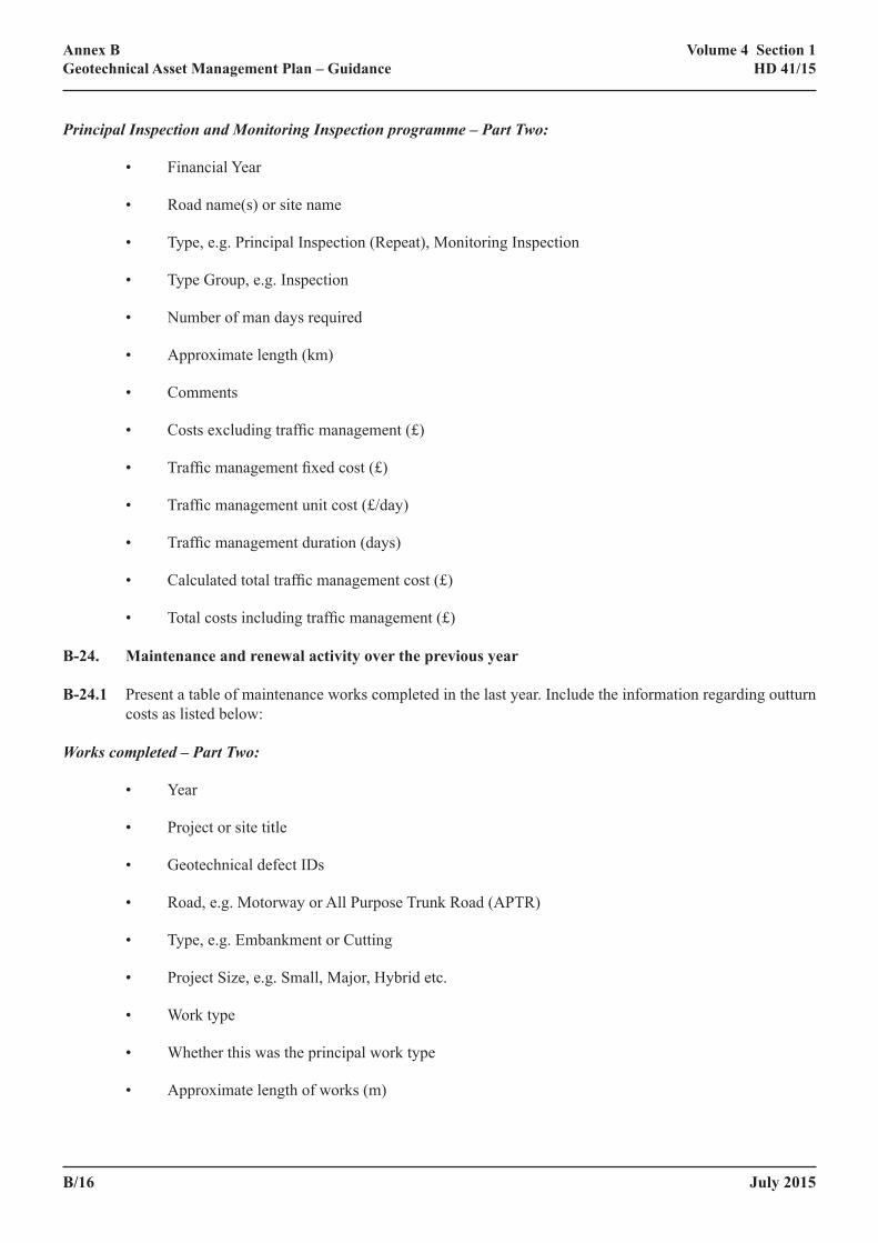
B/16 July 2015
Annex BGeotechnical Asset Management Plan – Guidance
Volume 4 Section 1HD 41/15
Principal Inspection and Monitoring Inspection programme – Part Two:
• Financial Year
• Road name(s) or site name
• Type, e.g. Principal Inspection (Repeat), Monitoring Inspection
• Type Group, e.g. Inspection
• Number of man days required
• Approximate length (km)
• Comments
• Costs excluding traffic management (£)
• Traffic management fixed cost (£)
• Traffic management unit cost (£/day)
• Traffic management duration (days)
• Calculated total traffic management cost (£)
• Total costs including traffic management (£)
B‑24. Maintenance and renewal activity over the previous year
B‑24.1 Present a table of maintenance works completed in the last year. Include the information regarding outturn costs as listed below:
Works completed – Part Two:
• Year
• Project or site title
• Geotechnical defect IDs
• Road, e.g. Motorway or All Purpose Trunk Road (APTR)
• Type, e.g. Embankment or Cutting
• Project Size, e.g. Small, Major, Hybrid etc.
• Work type
• Whether this was the principal work type
• Approximate length of works (m)
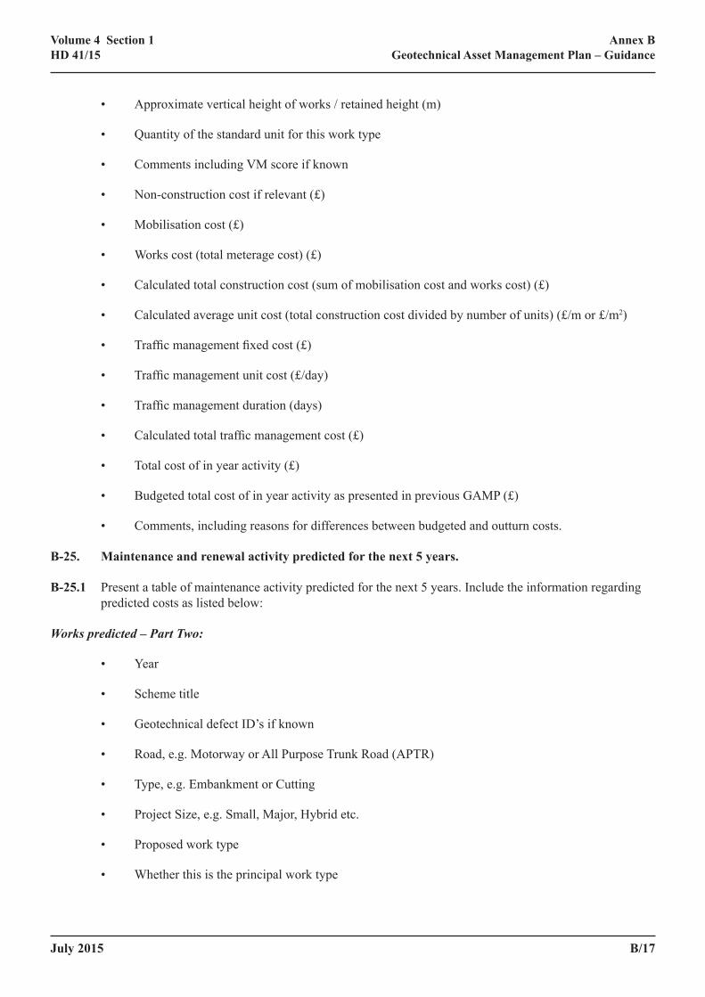
July 2015 B/17
Annex BGeotechnical Asset Management Plan – Guidance
Volume 4 Section 1HD 41/15
• Approximate vertical height of works / retained height (m)
• Quantity of the standard unit for this work type
• Comments including VM score if known
• Non-construction cost if relevant (£)
• Mobilisation cost (£)
• Works cost (total meterage cost) (£)
• Calculated total construction cost (sum of mobilisation cost and works cost) (£)
• Calculated average unit cost (total construction cost divided by number of units) (£/m or £/m2)
• Traffic management fixed cost (£)
• Traffic management unit cost (£/day)
• Traffic management duration (days)
• Calculated total traffic management cost (£)
• Total cost of in year activity (£)
• Budgeted total cost of in year activity as presented in previous GAMP (£)
• Comments, including reasons for differences between budgeted and outturn costs.
B‑25. Maintenance and renewal activity predicted for the next 5 years.
B‑25.1 Present a table of maintenance activity predicted for the next 5 years. Include the information regarding predicted costs as listed below:
Works predicted – Part Two:
• Year
• Scheme title
• Geotechnical defect ID’s if known
• Road, e.g. Motorway or All Purpose Trunk Road (APTR)
• Type, e.g. Embankment or Cutting
• Project Size, e.g. Small, Major, Hybrid etc.
• Proposed work type
• Whether this is the principal work type

B/18 July 2015
Annex BGeotechnical Asset Management Plan – Guidance
Volume 4 Section 1HD 41/15
• Approximate length of works (m)
• Approximate vertical height of works / retained height (m)
• Quantity of the standard unit for this work type
• Comments including prioritisation
• Estimated traffic management cost (£)
• Estimated construction cost (£)
• Estimated total cost
• Budgeted total cost as presented in previous GAMP (£)
• Comments
B‑26. Lessons learned / good practice
B‑26.1 Include details of any aspects of data management, planning, inspection or maintenance that could be adopted as good practice, together with any recommendations for changes in processes or methods. Consider whether this information can also be included in Part One, to enable the Overseeing Organisation to inform others of good practice.

July 2015 C/1
Annex CInformation Requirements
Volume 4 Section 1HD 41/15
ANNEX C – INFORMATION REQUIREMENTS

C/2 July 2015
Annex CInformation Requirements
Volume 4 Section 1HD 41/15
Table of Contents
C‑1. Implementation ......................................................................................................................................C/1
C‑2. Inspection information ..........................................................................................................................C/1
C‑3. Geotechnical asset information ............................................................................................................C/4
C‑4. Observation information.......................................................................................................................C/9
C‑5. Geotechnical Event information ..........................................................................................................C/18
C‑6. Scheme information...............................................................................................................................C/22
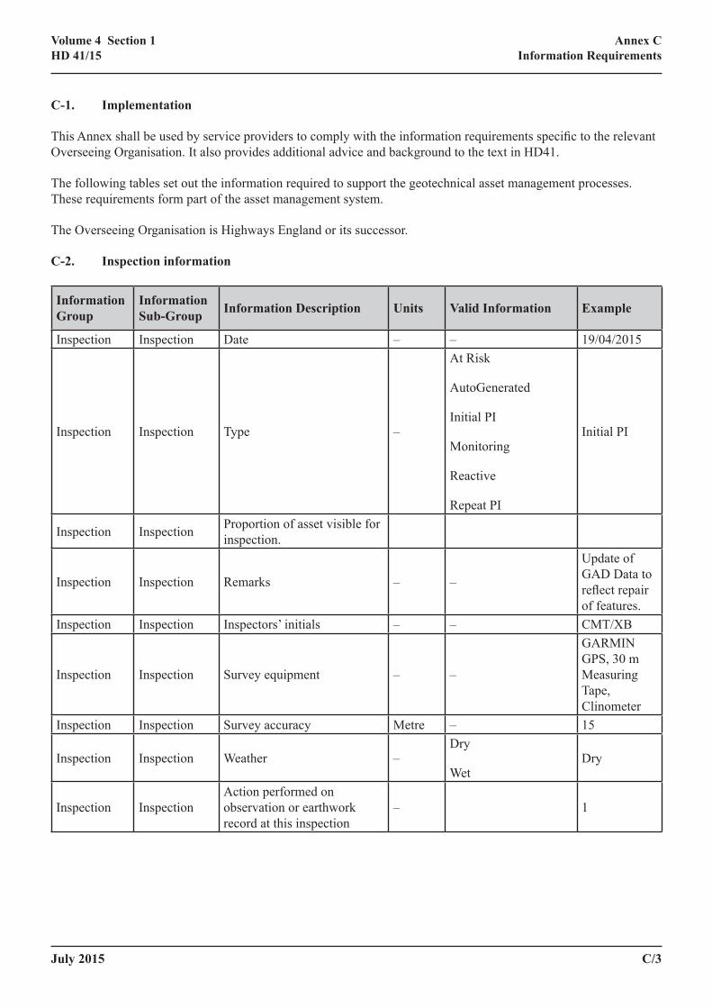
July 2015 C/3
Annex CInformation Requirements
Volume 4 Section 1HD 41/15
C‑1. Implementation
This Annex shall be used by service providers to comply with the information requirements specific to the relevant Overseeing Organisation. It also provides additional advice and background to the text in HD41.
The following tables set out the information required to support the geotechnical asset management processes. These requirements form part of the asset management system.
The Overseeing Organisation is Highways England or its successor.
C‑2. Inspection information
Information Group
Information Sub‑Group Information Description Units Valid Information Example
Inspection Inspection Date – – 19/04/2015
Inspection Inspection Type –
At Risk
AutoGenerated
Initial PI
Monitoring
Reactive
Repeat PI
Initial PI
Inspection Inspection Proportion of asset visible for inspection.
Inspection Inspection Remarks – –
Update of GAD Data to reflect repair of features.
Inspection Inspection Inspectors’ initials – – CMT/XB
Inspection Inspection Survey equipment – –
GARMIN GPS, 30 m Measuring Tape, Clinometer
Inspection Inspection Survey accuracy Metre – 15
Inspection Inspection Weather –Dry
WetDry
Inspection InspectionAction performed on observation or earthwork record at this inspection
– 1
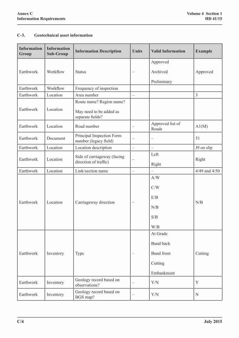
C/4 July 2015
Annex CInformation Requirements
Volume 4 Section 1HD 41/15
C‑3. Geotechnical asset information
Information Group
Information Sub‑Group Information Description Units Valid Information Example
Earthwork Workflow Status –
Approved
Archived
Preliminary
Approved
Earthwork Workflow Frequency of inspectionEarthwork Location Area number – 3
Earthwork Location
Route name? Region name?
May need to be added as separate fields?
Earthwork Location Road number – Approved list of Roads A1(M)
Earthwork Document Principal Inspection Form number (legacy field) – – 51
Earthwork Location Location description – – J9 on slip
Earthwork Location Side of carriageway (facing direction of traffic) –
Left
RightRight
Earthwork Location Link/section name – – 4/49 and 4/50
Earthwork Location Carriageway direction –
A/W
C/W
E/B
N/B
S/B
W/B
N/B
Earthwork Inventory Type –
At Grade
Bund back
Bund front
Cutting
Embankment
Cutting
Earthwork Inventory Geology record based on observations? – Y/N Y
Earthwork Inventory Geology record based on BGS map? – Y/N N
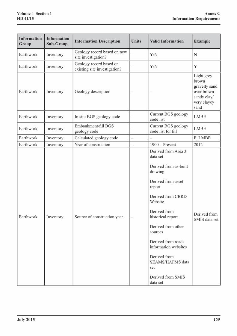
July 2015 C/5
Annex CInformation Requirements
Volume 4 Section 1HD 41/15
Information Group
Information Sub‑Group Information Description Units Valid Information Example
Earthwork Inventory Geology record based on new site investigation? – Y/N N
Earthwork Inventory Geology record based on existing site investigation? – Y/N Y
Earthwork Inventory Geology description – –
Light grey brown gravelly sand over brown sandy clay/very clayey sand
Earthwork Inventory In situ BGS geology code – Current BGS geology code list LMBE
Earthwork Inventory Embankment/fill BGS geology code – Current BGS geology
code list for fill LMBE
Earthwork Inventory Calculated geology code – – F_LMBEEarthwork Inventory Year of construction – 1900 – Present 2012
Earthwork Inventory Source of construction year –
Derived from Area 3 data set
Derived from as-built drawing
Derived from asset report
Derived from CBRD Website
Derived from historical report
Derived from other sources
Derived from roads information websites
Derived from SEAMS/HAPMS data set
Derived from SMIS data set
Derived from SMIS data set
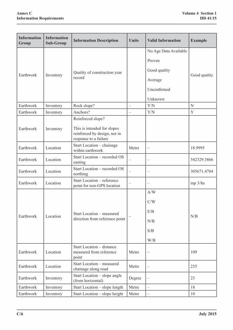
C/6 July 2015
Annex CInformation Requirements
Volume 4 Section 1HD 41/15
Information Group
Information Sub‑Group Information Description Units Valid Information Example
Earthwork Inventory Quality of construction year record
No Age Data Available
Proven
Good quality
Average
Unconfirmed
Unknown
Good quality
Earthwork Inventory Rock slope? – Y/N NEarthwork Inventory Anchors? – Y/N Y
Earthwork Inventory
Reinforced slope?
This is intended for slopes reinforced by design, not in response to a failure
Earthwork Location Start Location – chainage within earthwork Metre – 18.9995
Earthwork Location Start Location – recorded OS easting – – 542329.3866
Earthwork Location Start Location – recorded OS northing – – 305671.4784
Earthwork Location Start Location – reference point for non-GPS location – – mp 3/8a
Earthwork Location Start Location – measured direction from reference point –
A/W
C/W
E/B
N/B
S/B
W/B
N/B
Earthwork LocationStart Location – distance measured from reference point
Metre – 109
Earthwork Location Start Location – measured chainage along road Metre – 235
Earthwork Inventory Start Location – slope angle (from horizontal) Degree – 23
Earthwork Inventory Start Location – slope length Metre – 18Earthwork Inventory Start Location – slope height Metre – 10

July 2015 C/7
Annex CInformation Requirements
Volume 4 Section 1HD 41/15
Information Group
Information Sub‑Group Information Description Units Valid Information Example
Earthwork Inventory Start Location – slope morphology factor – – 36
Earthwork Inventory Start Location – slope bearing Degree North – 110
Earthwork Location Start Location – carriageway type –
L
M
R
SOFF
SON
SOFF
Earthwork Location End Location – chainage within earthwork Metre – 18.9995
Earthwork Location End Location – recorded OS easting – – 542329.3866
Earthwork Location End Location – recorded OS northing – – 305671.4784
Earthwork Location End Location – reference point for non-GPS location – – mp 3/8a
Earthwork Location End Location – measured direction from reference point –
A/W
C/W
E/B
N/B
S/B
W/B
N/B
Earthwork LocationEnd Location – distance measured from reference point
Metre – 109
Earthwork Location End Location – measured chainage along road Metre – 235
Earthwork Inventory End Location – slope angle (from horizontal) Degree – 23
Earthwork Inventory End Location – slope length Metre – 86Earthwork Inventory End Location – slope height Metre – 15
Earthwork Inventory End Location – slope morphology factor – – 36
Earthwork Inventory End Location – slope bearing Degree North – 110

C/8 July 2015
Annex CInformation Requirements
Volume 4 Section 1HD 41/15
Information Group
Information Sub‑Group Information Description Units Valid Information Example
Earthwork Location End Location – carriageway type –
L
M
R
SOFF
SON
SOFF
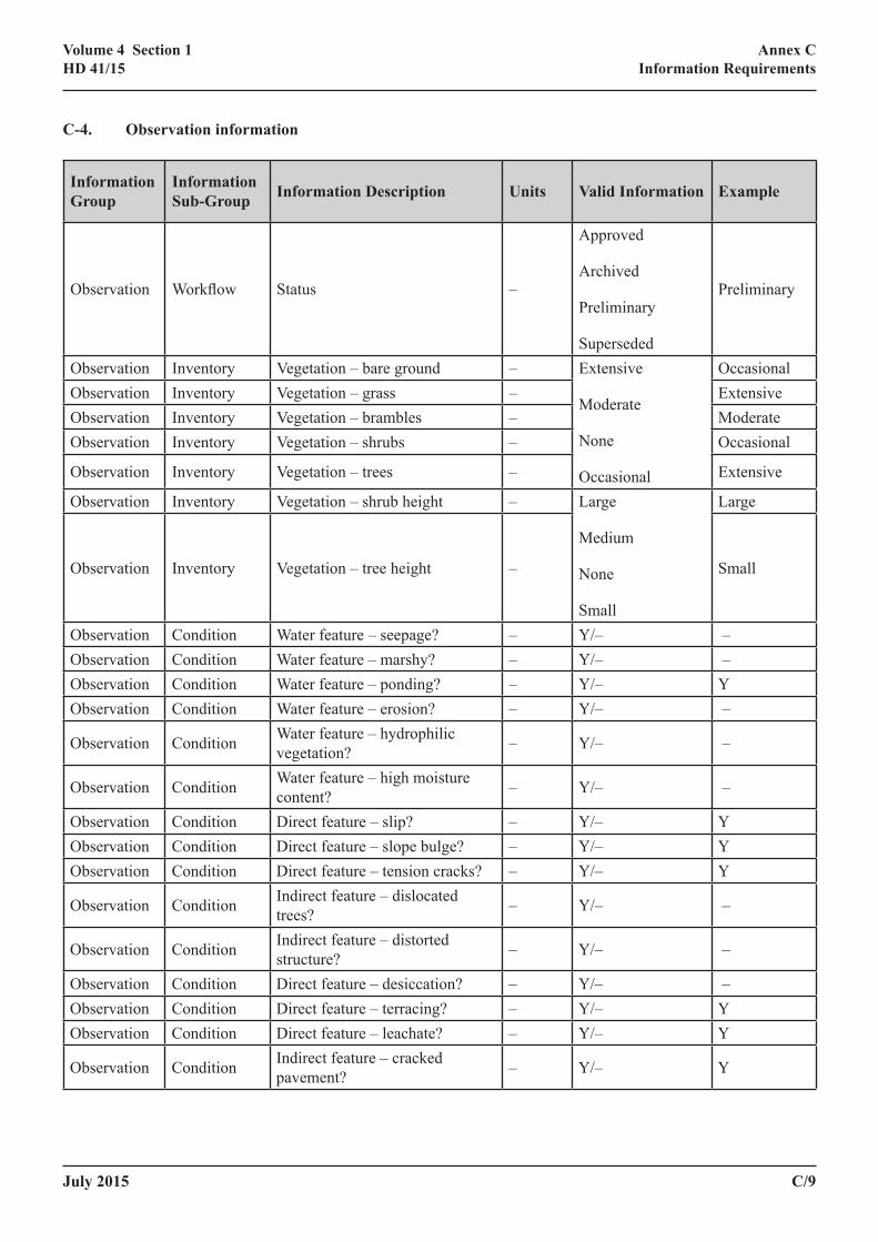
July 2015 C/9
Annex CInformation Requirements
Volume 4 Section 1HD 41/15
C‑4. Observation information
Information Group
Information Sub‑Group Information Description Units Valid Information Example
Observation Workflow Status –
Approved
Archived
Preliminary
Superseded
Preliminary
Observation Inventory Vegetation – bare ground – Extensive
Moderate
None
Occasional
OccasionalObservation Inventory Vegetation – grass – ExtensiveObservation Inventory Vegetation – brambles – ModerateObservation Inventory Vegetation – shrubs – Occasional
Observation Inventory Vegetation – trees – Extensive
Observation Inventory Vegetation – shrub height – Large
Medium
None
Small
Large
Observation Inventory Vegetation – tree height – Small
Observation Condition Water feature – seepage? – Y/– – Observation Condition Water feature – marshy? – Y/– – Observation Condition Water feature – ponding? – Y/– YObservation Condition Water feature – erosion? – Y/– –
Observation Condition Water feature – hydrophilic vegetation? – Y/– –
Observation Condition Water feature – high moisture content? – Y/– –
Observation Condition Direct feature – slip? – Y/– YObservation Condition Direct feature – slope bulge? – Y/– YObservation Condition Direct feature – tension cracks? – Y/– Y
Observation Condition Indirect feature – dislocated trees? – Y/– –
Observation Condition Indirect feature – distorted structure? – Y/– –
Observation Condition Direct feature – desiccation? – Y/– – Observation Condition Direct feature – terracing? – Y/– YObservation Condition Direct feature – leachate? – Y/– Y
Observation Condition Indirect feature – cracked pavement? – Y/– Y
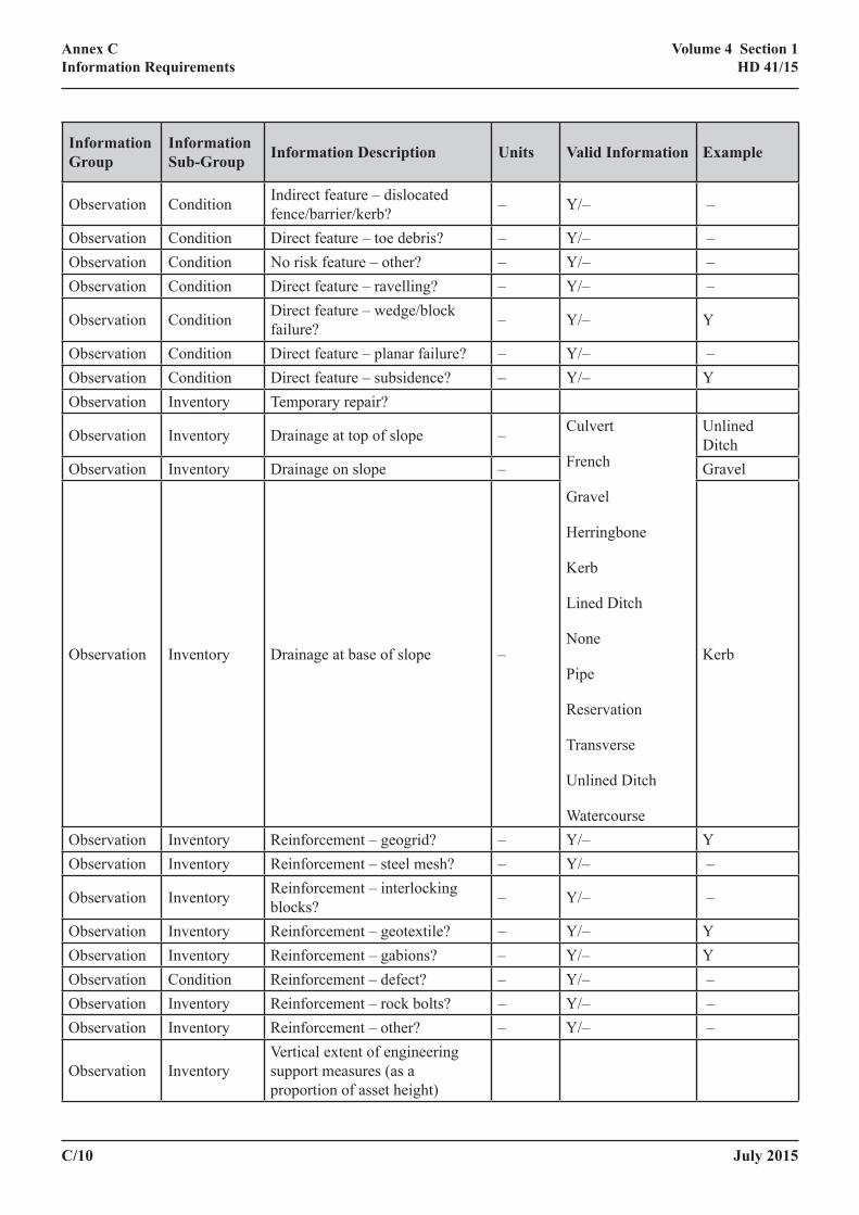
C/10 July 2015
Annex CInformation Requirements
Volume 4 Section 1HD 41/15
Information Group
Information Sub‑Group Information Description Units Valid Information Example
Observation Condition Indirect feature – dislocated fence/barrier/kerb? – Y/– –
Observation Condition Direct feature – toe debris? – Y/– – Observation Condition No risk feature – other? – Y/– – Observation Condition Direct feature – ravelling? – Y/– –
Observation Condition Direct feature – wedge/block failure? – Y/– Y
Observation Condition Direct feature – planar failure? – Y/– – Observation Condition Direct feature – subsidence? – Y/– YObservation Inventory Temporary repair?
Observation Inventory Drainage at top of slope – Culvert
French
Gravel
Herringbone
Kerb
Lined Ditch
None
Pipe
Reservation
Transverse
Unlined Ditch
Watercourse
Unlined Ditch
Observation Inventory Drainage on slope – Gravel
Observation Inventory Drainage at base of slope – Kerb
Observation Inventory Reinforcement – geogrid? – Y/– YObservation Inventory Reinforcement – steel mesh? – Y/– –
Observation Inventory Reinforcement – interlocking blocks? – Y/– –
Observation Inventory Reinforcement – geotextile? – Y/– YObservation Inventory Reinforcement – gabions? – Y/– YObservation Condition Reinforcement – defect? – Y/– – Observation Inventory Reinforcement – rock bolts? – Y/– – Observation Inventory Reinforcement – other? – Y/– –
Observation InventoryVertical extent of engineering support measures (as a proportion of asset height)
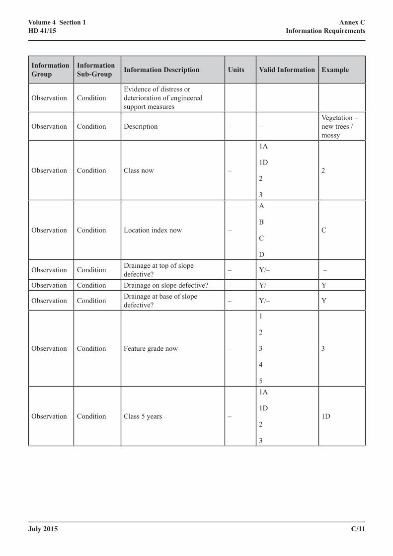
July 2015 C/11
Annex CInformation Requirements
Volume 4 Section 1HD 41/15
Information Group
Information Sub‑Group Information Description Units Valid Information Example
Observation ConditionEvidence of distress or deterioration of engineered support measures
Observation Condition Description – –Vegetation – new trees / mossy
Observation Condition Class now –
1A
1D
2
3
2
Observation Condition Location index now –
A
B
C
D
C
Observation Condition Drainage at top of slope defective? – Y/– –
Observation Condition Drainage on slope defective? – Y/– Y
Observation Condition Drainage at base of slope defective? – Y/– Y
Observation Condition Feature grade now –
1
2
3
4
5
3
Observation Condition Class 5 years –
1A
1D
2
3
1D
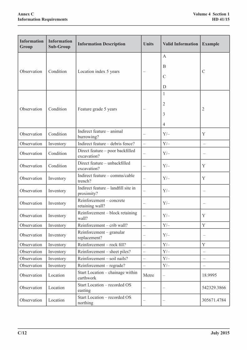
C/12 July 2015
Annex CInformation Requirements
Volume 4 Section 1HD 41/15
Information Group
Information Sub‑Group Information Description Units Valid Information Example
Observation Condition Location index 5 years –
A
B
C
D
C
Observation Condition Feature grade 5 years –
1
2
3
4
2
Observation Condition Indirect feature – animal burrowing? – Y/– Y
Observation Inventory Indirect feature – debris fence? – Y/– –
Observation Condition Direct feature – poor backfilled excavation? – Y/– –
Observation Condition Direct feature – unbackfilled excavation? – Y/– Y
Observation Inventory Indirect feature – comms/cable trench? – Y/– Y
Observation Inventory Indirect feature – landfill site in proximity? – Y/– –
Observation Inventory Reinforcement – concrete retaining wall? – Y/– –
Observation Inventory Reinforcement – block retaining wall? – Y/– Y
Observation Inventory Reinforcement – crib wall? – Y/– Y
Observation Inventory Reinforcement – granular replacement? – Y/– –
Observation Inventory Reinforcement – rock fill? – Y/– YObservation Inventory Reinforcement – sheet piles? – Y/– – Observation Inventory Reinforcement – soil nails? – Y/– – Observation Inventory Reinforcement – regrade? – Y/– –
Observation Location Start Location – chainage within earthwork Metre – 18.9995
Observation Location Start Location – recorded OS easting – – 542329.3866
Observation Location Start Location – recorded OS northing – – 305671.4784
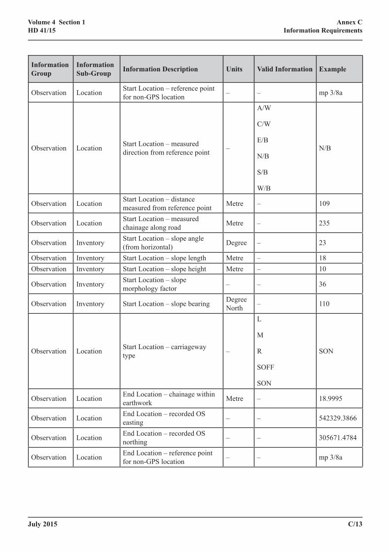
July 2015 C/13
Annex CInformation Requirements
Volume 4 Section 1HD 41/15
Information Group
Information Sub‑Group Information Description Units Valid Information Example
Observation Location Start Location – reference point for non-GPS location – – mp 3/8a
Observation Location Start Location – measured direction from reference point –
A/W
C/W
E/B
N/B
S/B
W/B
N/B
Observation Location Start Location – distance measured from reference point Metre – 109
Observation Location Start Location – measured chainage along road Metre – 235
Observation Inventory Start Location – slope angle (from horizontal) Degree – 23
Observation Inventory Start Location – slope length Metre – 18Observation Inventory Start Location – slope height Metre – 10
Observation Inventory Start Location – slope morphology factor – – 36
Observation Inventory Start Location – slope bearing Degree North – 110
Observation Location Start Location – carriageway type –
L
M
R
SOFF
SON
SON
Observation Location End Location – chainage within earthwork Metre – 18.9995
Observation Location End Location – recorded OS easting – – 542329.3866
Observation Location End Location – recorded OS northing – – 305671.4784
Observation Location End Location – reference point for non-GPS location – – mp 3/8a
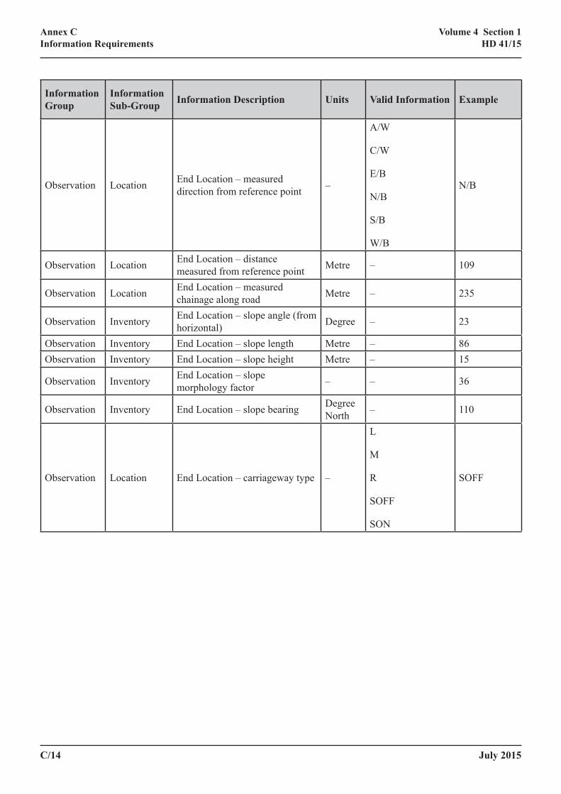
C/14 July 2015
Annex CInformation Requirements
Volume 4 Section 1HD 41/15
Information Group
Information Sub‑Group Information Description Units Valid Information Example
Observation Location End Location – measured direction from reference point –
A/W
C/W
E/B
N/B
S/B
W/B
N/B
Observation Location End Location – distance measured from reference point Metre – 109
Observation Location End Location – measured chainage along road Metre – 235
Observation Inventory End Location – slope angle (from horizontal) Degree – 23
Observation Inventory End Location – slope length Metre – 86Observation Inventory End Location – slope height Metre – 15
Observation Inventory End Location – slope morphology factor – – 36
Observation Inventory End Location – slope bearing Degree North – 110
Observation Location End Location – carriageway type –
L
M
R
SOFF
SON
SOFF
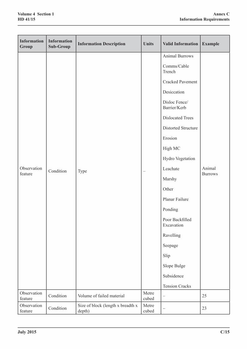
July 2015 C/15
Annex CInformation Requirements
Volume 4 Section 1HD 41/15
Information Group
Information Sub‑Group Information Description Units Valid Information Example
Observation feature Condition Type –
Animal Burrows
Comms/Cable Trench
Cracked Pavement
Desiccation
Disloc Fence/Barrier/Kerb
Dislocated Trees
Distorted Structure
Erosion
High MC
Hydro Vegetation
Leachate
Marshy
Other
Planar Failure
Ponding
Poor Backfilled Excavation
Ravelling
Seepage
Slip
Slope Bulge
Subsidence
Tension Cracks
Animal Burrows
Observation feature Condition Volume of failed material Metre
cubed – 25
Observation feature Condition Size of block (length x breadth x
depth)Metre cubed – 23

C/16 July 2015
Annex CInformation Requirements
Volume 4 Section 1HD 41/15
Information Group
Information Sub‑Group Information Description Units Valid Information Example
Observation feature Condition Length Metre – 40
Observation feature Condition Breadth Metre – 34
Observation feature Condition Depth Metre – 6.874
Observation feature Condition Density (no. per
m2) – 4
Observation feature Condition Horizontal misalignment Metre – 1.867
Observation feature Condition Vertical misalignment Metre – 0
Observation feature Condition Angular distortion Degrees – 30
Observation feature Condition Flow rate Litres/
min – 0.05
Observation feature Condition Min distance to running lane Metre – 12.5
Observation feature Condition Min distance to comms cable Metre – 5
Observation feature Condition Min distance to hard shoulder Metre – 6
Observation feature Condition Min distance to inhabited builds Metre – 89
Observation feature Condition Min distance to safety barrier Metre – 5.3
Observation feature Condition Min distance to non-inhab builds Metre – 4
Observation feature Condition Min distance to comms cabinet Metre – 4
Observation feature Condition Min distance to structure Metre – 11
Observation feature Condition Min distance to drainage Metre – 76
Observation feature Condition Min distance to pylon Metre – 2.3
Observation feature Condition Min distance to other Metre – 1.5
Observation feature Condition Min distance to boundary Metre – 10
Observation feature Condition Description of ‘other’ – – From crest of
slope

July 2015 C/17
Annex CInformation Requirements
Volume 4 Section 1HD 41/15
Information Group
Information Sub‑Group Information Description Units Valid Information Example
Observation feature Condition Comment – –
Comprises two failures. 1st failure 5m length, 2nd failure 9m length.
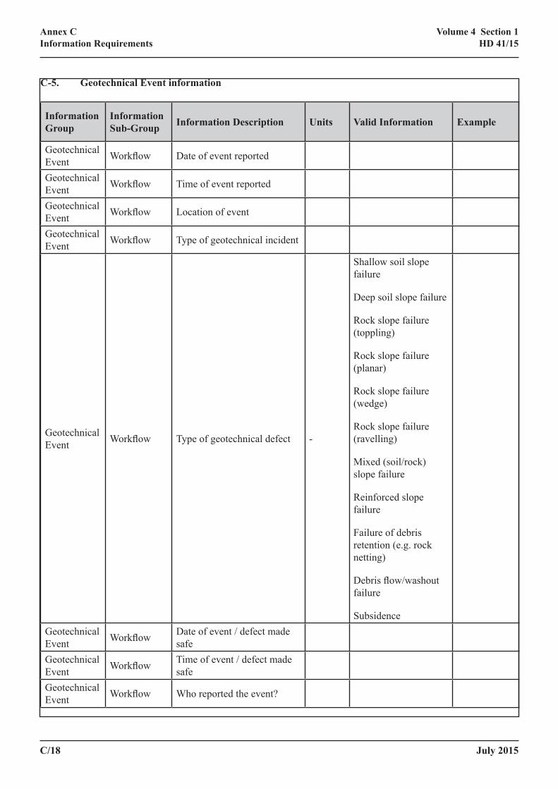
C/18 July 2015
Annex CInformation Requirements
Volume 4 Section 1HD 41/15
C‑5. Geotechnical Event information
Information Group
Information Sub‑Group Information Description Units Valid Information Example
Geotechnical Event Workflow Date of event reported
Geotechnical Event Workflow Time of event reported
Geotechnical Event Workflow Location of event
Geotechnical Event Workflow Type of geotechnical incident
Geotechnical Event Workflow Type of geotechnical defect -
Shallow soil slope failure
Deep soil slope failure
Rock slope failure (toppling)
Rock slope failure (planar)
Rock slope failure (wedge)
Rock slope failure (ravelling)
Mixed (soil/rock) slope failure
Reinforced slope failure
Failure of debris retention (e.g. rock netting)
Debris flow/washout failure
SubsidenceGeotechnical Event Workflow Date of event / defect made
safeGeotechnical Event Workflow Time of event / defect made
safeGeotechnical Event Workflow Who reported the event?
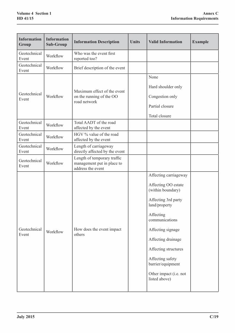
July 2015 C/19
Annex CInformation Requirements
Volume 4 Section 1HD 41/15
Information Group
Information Sub‑Group Information Description Units Valid Information Example
Geotechnical Event Workflow Who was the event first
reported too?Geotechnical Event Workflow Brief description of the event
Geotechnical Event Workflow
Maximum effect of the event on the running of the OO road network
None
Hard shoulder only
Congestion only
Partial closure
Total closureGeotechnical Event Workflow Total AADT of the road
affected by the eventGeotechnical Event Workflow HGV % value of the road
affected by the eventGeotechnical Event Workflow Length of carriageway
directly affected by the event
Geotechnical Event Workflow
Length of temporary traffic management put in place to address the event
Geotechnical Event Workflow How does the event impact
others
Affecting carriageway
Affecting OO estate (within boundary)
Affecting 3rd party land/property
Affecting communications
Affecting signage
Affecting drainage
Affecting structures
Affecting safety barrier/equipment
Other impact (i.e. not listed above)

C/20 July 2015
Annex CInformation Requirements
Volume 4 Section 1HD 41/15
Information Group
Information Sub‑Group Information Description Units Valid Information Example
Geotechnical Event Workflow Where ‘Other impact’ is
chosen, describe the impact
Geotechnical Event Workflow What is the likely cause of
the event
Oversteepened slope
Blocked drainage
Exceptional rainfall
Inadequate maintenance
Utility failure
Lack of vegetation
Poorly backfilled excavation
Non-backfilled excavation
Animal burrowing
Inadequate drainage
Poor construction
Unknown
Other cause (i.e. not listed above)
Geotechnical Event Workflow Where ‘Other cause’ is
chosen, describe the impact
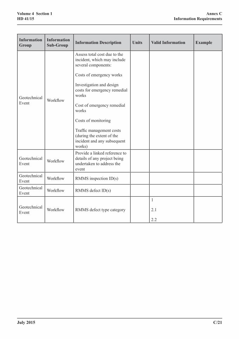
July 2015 C/21
Annex CInformation Requirements
Volume 4 Section 1HD 41/15
Information Group
Information Sub‑Group Information Description Units Valid Information Example
Geotechnical Event Workflow
Assess total cost due to the incident, which may include several components:
Costs of emergency works
Investigation and design costs for emergency remedial works
Cost of emergency remedial works
Costs of monitoring
Traffic management costs (during the extent of the incident and any subsequent works)
Geotechnical Event Workflow
Provide a linked reference to details of any project being undertaken to address the event
Geotechnical Event Workflow RMMS inspection ID(s)
Geotechnical Event Workflow RMMS defect ID(s)
Geotechnical Event Workflow RMMS defect type category
1
2.1
2.2
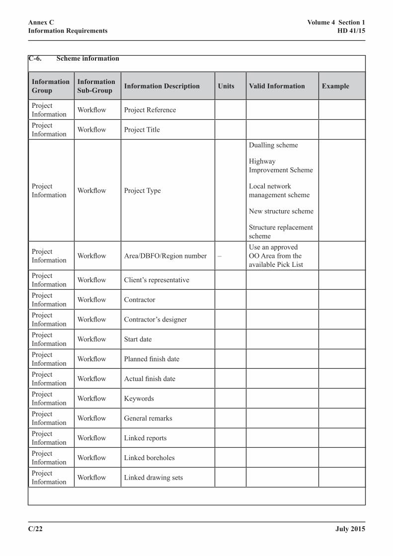
C/22 July 2015
Annex CInformation Requirements
Volume 4 Section 1HD 41/15
C‑6. Scheme information
Information Group
Information Sub‑Group Information Description Units Valid Information Example
Project Information Workflow Project Reference
Project Information Workflow Project Title
Project Information Workflow Project Type
Dualling scheme
Highway Improvement Scheme
Local network management scheme
New structure scheme
Structure replacement scheme
Project Information Workflow Area/DBFO/Region number –
Use an approved OO Area from the available Pick List
Project Information Workflow Client’s representative
Project Information Workflow Contractor
Project Information Workflow Contractor’s designer
Project Information Workflow Start date
Project Information Workflow Planned finish date
Project Information Workflow Actual finish date
Project Information Workflow Keywords
Project Information Workflow General remarks
Project Information Workflow Linked reports
Project Information Workflow Linked boreholes
Project Information Workflow Linked drawing sets

July 2015 C/23
Annex CInformation Requirements
Volume 4 Section 1HD 41/15
Information Group
Information Sub‑Group Information Description Units Valid Information Example
Project Information Workflow Linked located files
Project Information Workflow Linked Geotechnical Events
Project Information Workflow Linked observations
Project Information Workflow Linked roads
Project Information Workflow Contact details

C/24 July 2015
Volume 4 Section 1HD 41/15

Design Manual for Roads and Bridges Volume 4 Geotechnics and Drainage Section 1 Earthworks Part 3 HD41/15 Maintenance of Highway Geotechnical Assets ISBN 9780115534065 ‐‐‐‐‐‐‐‐‐‐‐‐‐‐‐‐‐‐‐‐‐‐‐‐‐‐‐‐‐‐‐‐‐‐‐‐‐‐‐‐‐‐‐‐‐‐‐‐‐‐‐‐‐‐‐‐‐‐‐‐‐‐‐‐‐‐‐‐‐‐‐‐‐‐‐‐‐‐‐‐‐‐‐‐‐‐‐‐‐‐‐‐‐‐‐‐‐‐‐‐‐‐‐‐‐‐‐‐‐‐‐‐‐‐‐‐‐‐‐‐‐‐‐‐‐‐‐‐‐‐‐ For information on the content of either The Manual of Contract Documents for Highway Works or Design Manual for Roads and Bridges, please e‐mail your enquiry to: [email protected] For all other enquiries including ordering publications or information on latest issues and pricing, please contact TSO. To ensure that you automatically receive the latest amendments to these manuals please contact TSO with a request to take out a standing order for the relevant manual(s) you require.
Published by TSO (The Stationery Office), part of Williams Lea, and available from: Online www.tsoshop.co.uk Mail, Telephone, Fax & E-mail TSO PO Box 29, Norwich, NR3 1GN Telephone orders/General enquiries: 0333 202 5070 Fax orders: 0333 202 5080 E-mail: [email protected] Textphone 0333 202 5077 TSO@Blackwell and other Accredited Agents