volume 1 - apc by schneider electric · as a system using integrated management tools. ... an...
TRANSCRIPT

CCSSII 22000044 MMaasstteerrFFoorrmmaatt™
Physical infrastructure for a scalable, adaptable, efficient, reliable, predictable data center with 5 to 100 racks
OOppttiimmiizzeedd ffoorr SSmmaallll aanndd MMeeddiiuumm DDaattaa CCeenntteerrss
Rev 2 February 2012
VOLUME 1
©2012 Schneider Electric. All Rights Reserved. Schneider Electric and APC are trademarks owned by
Schneider Electric Industries SAS or its affiliated companies.

ii Rev 2 February 2012
Scope of this book This book is a specification for a small to medium data center of 5-100 racks. For smaller installations, please refer to the APC Press companion book, System Specification and Project Manual, Volume 2: Optimized for Telecom / Networking / Server Rooms. For larger installations, this book cannot replace the services of a qualified consulting engineer, although it can be used as a reference and educational resource for the user as the system is being designed.
Format of this book This book is directed toward the data center IT community – it is therefore organized specifically toward the IT viewpoint of the data center design/ build process, not toward the general construction of a building. Facilities and trades personnel will notice that the format of this specification deviates from the way construction specifications are usually published, and does not strictly follow CSI division ordering, although all items are numbered according to CSI MasterFormat 2004.
This book is divided into three parts:
STANDARD PROCESS - Overview of the standardized data center design/ build project process (Section 2) To be read and reviewed by data center personnel
This part of the book illustrates how project phases, steps, and tasks relate to each other in sequence, to accomplish the work needed to create the system. USER REQUIREMENTS – Forms for gathering user-specific data for this project (Section 3)
To be filled out by data center personnel with data center consultant
The data gathered in this part of the book will be used to generate an appropriate design for the system. It also includes checklists for documenting who will assume the various roles and responsibilities of the project’s process.
STANDARD SYSTEM SPECIFICATION - The common “rules” for building any small/medium (Sections 4-11) data center
To be reviewed by IT and Facilities
This part of the book provides detailed specifications for building a standardized data center including power, cooling, fire suppression, security, management, and racks. This standard specification uses the 2004 edition MasterFormat CSI numbering system.
The authors would like to acknowledge the work and dedication of the APC Data Center Science Center team that created this System Specification and Project Manual. Thanks to Neil Rasmussen, Chief Technology Officer and Suzanne Niles, Senior Research Analyst, for providing vision and a clear definition of processes. Thanks to Victor Avelar and Wendy Torell, both Senior Research Analysts, for the hours they dedicated to clarifying the user specifications section of this book. In addition, thanks to Dennis Bouley, Senior Research Analyst, for providing professional editorial expertise and for consistently advocating the customer’s point of view. Finally, we would like to thank Paul Marcoux, former Director of the Data Center Science Center, for authoring the bulk of the standard specifications and for sharing his extensive knowledge of data center design drawn from his many years of experience in the data center design/build industry.
The information contained in this publication is provided as is and has been prepared solely for the purpose of evaluating data center design and construction. American Power Conversion Corporation makes no representation and no warranty is given, either expressed or implied, as to the completeness or accuracy of the information contained herein. The information in this publication should not be used for financing purposes of any kind.
In no event shall American Power Conversion Corporation be liable for any direct, indirect, consequential, punitive, special, or incidental damages (including, without limitation, damages for loss of business, contract, revenue, data, information, or business interruption) resulting from, arising out of, or in connection with the use of, or inability to use, this publication or its content, even if American Power Conversion Corporation has been expressly advised of the possibility of such damages. American Power Conversion Corporation reserves the right to make changes or updates with respect to or in the content of this publication or the format thereof at any time without notice.
Copyright, intellectual, and all other proprietary rights in the content (including but not limited to software, audio, video, text, and photographs) rests with American Power Conversion Corporation or its licensors. All rights in the content not expressly granted herein are reserved. No rights of any kind are licensed or assigned or shall otherwise pass to persons accessing this information. This publication shall not be for resale in whole or in part.
Rights granted American Power Conversion Corporation grants the user of this publication the right to copy any line or lines, diagrams, photographs, or designs in sections 4 through 10, provided the use of the copied material is for use within the user’s specific evaluation, design, and construction project. Copied material shall not be used in whole or in part either electronically or physically for use outside a specific evaluation, design, and construction project or for individual or company material gain or volume reproduction.
APC Part Number: 990-9455 APC Press ISBN 0-9713658-0-6

iii Rev 2 February 2012
CCSSII 22000044 MMaasstteerrFFoorrmmaatt™
SSyysstteemm SSppeecciiffiiccaattiioonn aanndd PPrroojjeecctt MMaannuuaall Physical infrastructure for a scalable, adaptable, efficient, and predictable data center
1
SYSTEM and PROCESS Preferences/Constraints
Racks
Power
Cooling
Management
Room
General and System Level
12
Fire Protection
11 Acronyms Glossary Appendices Index
Physical Security

iv Rev 2 February 2012
CCSSII DDiivviissiioonn LLooccaattoorr This book is organized around the major elements of data center physical infrastructure Although a data center requires physical construction as with any facility, the taxonomy of its elements is slightly different from the order and naming of the CSI (Construction Specification Institute) MasterFormat system, which was designed to categorize elements of conventional “brick-and-mortar” construction. Here is where the CSI MasterFormat divisions are located in the tabbed sections of this book: CSI Division
Section of This Book
Division 00 Tab 2 Project Process Procurement and Contracting Division 01 Tab 2 Project Process General Requirements Division 07 Tab 5 Room Thermal and Moisture Protection Division 09 Tab 5 Room Finishes Division 13 Tab 5 Room Special Construction Division 21 Tab 10 Fire Protection Fire Suppression Division 22 Tab 5 Room Plumbing Division 23 Tab 8 Cooling HVAC Division 25 Tab 9 Management Integrated Automation Division 26 Tab 7 Power Electrical Division 27 Tab 5 Room Communications Division 28 Tab 10 Fire Protection Electronic Safety and Security Tab 11 Physical Security

v Rev 2 February 2012
Tab #1 goes here

Small/Medium Data Center System Specification and Project Manual
1
Rev 2 February 2012
This specification describes a small-to-medium data center constructed in a room within an existing building using
modular, scalable, row-based rack/power/cooling architecture. This data center is
defined using a point-by-point specification of its physical system in combination with
a standardized process for executing the steps of its deployment.
The population of IT equipment to be supported by this physical infrastructure –
hence the power and cooling capacity required– will have been determined by earlier
needs assessment analysis, which establishes specific design requirements based
on current and projected business needs of the organization.
Whole-system approach
The purpose of this data center specification is not to provide detailed
descriptions of specific products, but rather to describe the essential
requirements of performance, interoperability, and best practice that will
allow all physical infrastructure elements to work together as an integrated
whole rather than as a custom-engineered collection of loosely related
components. Such a whole-system design optimizes functionality while
reducing cost, and can be managed as a system using integrated
management tools.
Standardized core of common requirements
Nonessential variations in physical infrastructure from data center to data
center – common in current-generation data centers – create a breeding ground for defects, delays, surprises, and
human error. These costly effects of one-time engineering have been mitigated in this specification by creating a
standardized core of best-practice requirements, which forms the central part of this book (Sections 4-11).
Maximizing the extent of standardization in the data center increases reliability, speeds deployment, drives out
defects and human error, reduces total cost of ownership, and fosters predictability of performance.
User-specific requirements for the data center – the essential design mandates
that ensure the data center meets a user’s particular needs regarding density,
redundancy, power/cooling architecture, and so on – are distinct from the common
specification and are logged in a separate section (Section 3). These user-
specific requirements serve as the “missing piece” that completes the standard
specification and makes it an actionable, complete specification for the user’s data
center.
What Is This Book? 1
Small/Medium Data Center
5-100 racks
Does not include wiring closets or telecom rooms
Standard (common) specification
User-specific elements
Maximizing the standardized part
simplifies the system and drives out defects
NCPI Elementsare combined into
an integrated system
andFire
SecurityCooling
Racksand
PhysicalStructure
Power
Cabling
ServicesManagement
Power
Fire
Cool
ing
Security
Racks
Physical infrastructure as integrated system
PPHHYYSSIICCAALL IINNFFRRAASSTTRRUUCCTTUURREE

Small/Medium Data Center System Specification and Project Manual
2
Rev 2 February 2012
PROCESS as part of the project
This specification includes requirements not only for the physical equipment and construction of the system that is
the outcome of the project, but also for elements of the process that carries out the execution of the project, such
as scheduling, site access, installation,
commissioning, and training. As with the physical
(system) specification, some of these process
elements will be standardized, and some will be
configured for the user-specific aspects of the
particular project at hand.
Multiple architectures supported
The standard specification in this book includes performance requirements and best practices that will apply to any
well-designed and constructed data center, as well items that can be selectively included to support the user’s
design decisions regarding a variety of alternative data center architectures, such as:
• Central vs. distributed UPS
• Central vs. distributed cooling
• Dropped ceiling vs. no dropped ceiling
• Raised floor vs. slab floor
Where there are choices to be made in the standard specification, the selection is based on the user-specific
requirements recorded in Section 3.
Mixed performance in the same room
Since this specification includes a user-specific set of requirements for this particular project – including a room
layout drawing with row/rack particulars as specific as the user desires – it allows for rows of racks, cooling
equipment, and power equipment to be configured for differing density, availability, and redundancy according to
the needs of the IT equipment supported by each row. For example, critical applications can have power, cooling,
and network infrastructure configured for 2N redundancy (see page 99 for definition) and reside in the same
computer room as non-critical configurations requiring only N+1 or N redundancy.
Availability, redundancy, and density goals, and the resulting power and cooling configurations they require, will
have been determined in earlier assessment and planning steps that establish the user-specific details of the
system specification.
Continued
TThhee
PPRROOJJEECCTT
The PROCESS
The SYSTEM creates
Prepare Implement Acquire Design

Small/Medium Data Center System Specification and Project Manual
3
Rev 2 February 2012
C 2+
Criticality tags
Criticality is a number from 1 to 4 representing how “important” the data center’s operation is to the business, in
terms of toleration for downtime. A data center’s criticality level represents a major decision in the planning
process since it impacts many other decisions including location, building type, fire suppression, security system,
and many others. The planning phase allows designers to balance the total cost of ownership of a data center with
the preferences and constraints of a business’s availability requirements. It is through this iterative planning
exercise that a final availability level is specified. In the standard system specification (Sections 4-11 of this book),
criticality “tags” are used to mark items that are for critically levels higher than criticality level 1. Criticality level 1 is
the default, if no tag is shown. Table 1 shows the meaning of these tags.
Table 1-1 – Meaning of criticality tags on Standard Specification items
Criticality Tag
Item applies to criticality level(s)...
No tag 1, 2, 3, 4
(All data centers)
2, 3, 4
3, 4
4
Specification items apply to all data centers (criticality levels 1-4) unless there is a tag indicating that the item
applies only to higher criticality. In the example below, item #1 applies to all data centers (criticality levels 1
through 4) because it shows no criticality tag. Item #2 applies only to data centers of criticality level 3 or higher.
1 Generator(s) installed outdoors shall be sheltered by an enclosure.
2 Walk-in enclosures shall house all generator mechanical, electrical, and fuel systems.
“Criticality” is an expansion of the familiar concept availability “tiers.” The selected criticality will determine the
major characteristics of the system architecture, such as redundancy of power and cooling systems, as well as the
robustness of system monitoring and various room construction details that affect reliability. Table 2 provides a
brief summary of criticality levels.
C 3+
C 4
C 3+
Lowest criticality
Highest criticality
Example of criticality “tag”

Small/Medium Data Center System Specification and Project Manual
4
Rev 2 February 2012
Criticality Level Business Characteristics Effect on System Design
1 (Lowest)
Typically small businesses; mostly cash-based; limited online presence; low dependence on IT; and perceive downtime as a tolerable inconvenience
Numerous single points of failure in all aspects of design; no generator; extremely vulnerable to inclement weather conditions; generally unable to sustain more than a 10 minute power outage.
2
Some amount of online revenue generation; multiple servers; phone system vital to business; dependent on email, some tolerance to scheduled downtime
Some redundancy in power and cooling systems; generator backup; able to sustain 24 hour power outage; minimal thought to site selection; vapor barrier; formal data room separate from other areas
3
World-wide presence; majority of revenue from online business; VoIP phone system; high dependence on IT; high cost of downtime; highly recognized brand
Two utility paths (active and passive); redundant power and cooling systems; redundant service providers; able to sustain 72-hour power outage; careful site selection planning; one-hour fire rating; allows for concurrent maintenance
4 (Highest)
Multi-million dollar business; majority of revenues from electronic transactions; business model entirely dependent on IT; extremely high cost of downtime
Two independent utility paths; 2N power and cooling systems; able to sustain 96 hour power outage; stringent site selection criteria; minimum two-hour fire rating; high level of physical security; 24/7 onsite maintenance staff
CSI MasterFormat 2004 numbering and the “NCPI” tag
MasterFormatTM is a numbering system created by the Construction Specifications Institute (CSI) for categorizing
construction specifications, much like the Dewey Decimal System for books in North America and Europe.
MasterFormat 2004, used in this specification, is the latest edition of this numbering system. While the physical
infrastructure elements of a data center do not align perfectly with the divisions and hierarchy of MasterFormat, the
specifications in this book have been aligned and labeled as closely as practicable with MasterFormat numbering.
To avoid possible conflict with an organization’s other, non-data-
center construction specifications (for example, in a construction
project involving both a data center and the building that contains it)
this book has assigned new, data-center-specific MasterFormat
subsections in the appropriate categories, using the MasterFormat
rules for creating new subsections. All data center specification
topics are tagged with “NCPI” in their CSI title, to distinguish them
from any similar specifications that apply to ordinary building construction.
Table 1-2 – Summary of criticality levels For a complete discussion of criticality levels, see APC White Paper #122, “Guidelines for Specification of Data Center Criticality / Tier Levels”
What is “NCPI”?
NCPI stands for “network-critical physical infrastructure,” a term sometimes used to refer to the physical infrastructure of a data center (the subject of this book). NCPI includes power, cooling, racks, fire protection, physical security, management, and services.

Small/Medium Data Center System Specification and Project Manual
5
Rev 2 February 2012
For organizational clarity the sections of this book reflect a data center perspective in the ordering and
categorization of the major infrastructure elements (power, cooling, management, etc.). While all specifications
appear in their correct MasterFormat divisions, the divisions themselves do not appear sequentially in their
MasterFormat numbered order. The correspondence between MasterFormat division numbers and the sections of
this book are shown on in the “CSI Division Locator” list on the back of the table of contents page.
How to mark items that do not apply, or conflict with other items
When using the standard system specification (Sections 4-11) as a basis for contract work, there is an industry
convention for marking items that do not apply to your project. Such items might represent higher criticality than is
needed, or they may be in conflict with other items that represent an alternative implementation (as in the choice
of fire suppression techniques), or may not be applicable to the project for some other reason. The proper way to
eliminate an item is to cross it out and mark it “NIC” (not in contract) as shown below. This retains a record of what
was eliminated from the contract.
Figure 1-1 – Correct method of eliminating items from contract specification
21 13 19.90 NCPI Preaction Sprinkler Systems
1 Sprinkler system shall be preaction type which shall not allow water to enter the sprinkler piping during an accidental breakage of a sprinkler head.
2 Sprinkler system shall be double-acting preaction type which shall combine preaction and smoke detection.
3 Sprinkler actuation system shall be armed by the initiation of an alarm from a cross-zoned detection system.
4 Sprinkler system design density shall conform to the owner’s / owner representative’s insurance company, lease agreement fire protection requirements, and local and national codes.
5 All sprinkler system plans and calculations shall be submitted to the authority having jurisdiction (AHJ) for review and approval prior to installation.
6 The following sprinkler system controls shall be included in fire alarm control panel:
a water flow switch
b PIV (post indicator valve) tamper switch
c sprinkler piping supervisory air pressure switch
7 In data centers with no suspended (drop) ceiling, sprinklers shall be configured upright.
NIC
NIC

Small/Medium Data Center System Specification and Project Manual
6
Rev 2 February 2012
Tab #2 goes here

Small/Medium Data Center System Specification and Project Manual
7
Rev 2 February 2012
SSppeecciiffiiccaattiioonn ooff tthhee tthhaatt ssuuppppoorrttss aanndd ccaarrrriieess oouutt tthhee eexxeeccuuttiioonn ooff tthhiiss pprroojjeecctt The success of the project depends not only on the acquisition and deployment of hardware, but equally upon the
successful execution of the process that guides the project through its phases from concept to deployment. The
process creates the system (Figure 2-1.)
Figure 2-1 – A project is comprised of the system plus the process that creates it
Every step of the process must be clearly defined, assigned to an owner, and tracked. Responsibilty for the
various process steps can be assumed by the user or outsourced to a hardware vendor or to a third-party service
provider. Regardless of who does what, it is essential that every step of the process be accounted for and
executed at the appropriate time, with each step providing input to subsequent steps that depend on it.
Project Process 2
TThhee
PPRROOJJEECCTT
The PROCESS
The SYSTEM creates
Prepare Implement Acquire Design

Small/Medium Data Center System Specification and Project Manual
8
Rev 2 February 2012
Process - General
1 Process shall be configured from the standard process map of Figure 2-2 as appropriate to the project:
2 All process steps in Figure 2-2 shall be evaluated for relevance to the project, and unneeded steps deleted.
3 Additional steps shall be added as necessary to handle extraordinary, non-standard activity.
4 Process flow and timing dependencies shall follow Figure 2-2, specifically:
a Process activity shall flow through all phases in sequence, left to right.
b Each phase shall have all its steps (listed vertically below it) completed before proceeding to the next phase.
c Asynchronous process elements, which handle unplanned changes and problems that can occur anywhere in the process, shall be executed as needed.
Figure 2-2 – Standardized project process
For more about this standardized process, see APC White Paper #140, “Data Center Projects: Standardized Process”
Can occur at any point in the process
Project change management
Process defect correction
Product defect correction
Each phase ends with a milestone
Milestones

Small/Medium Data Center System Specification and Project Manual
9
Rev 2 February 2012
5 Project information shall be maintained on a secure website accessible to all parties to the project. Website information shall include:
a Ongoing project status
b For each process step, intermediate and final data and reports
c The ability to accept feedback, comments, requests, and problem statements
6 Each step shall have the following elements (Figure 2-3)
a An owner
b A task list, consisting of work instructions and a checklist of specific actions to be completed
c A list of INPUTS, which are the outputs of previous steps
d A list of OUTPUTS, which become the inputs to subsequent steps
Figure 2-3 – Step detail
INPUTS Data from previous steps
OUTPUTS Data needed by subsequent steps
This step owned by
Task Work Instructions
Task Checklist
For more about process steps, see APC White Paper #140, “Data Center Projects: Standardized Process”

Small/Medium Data Center System Specification and Project Manual
10
Rev 2 February 2012
Task Detail The bulleted items in Figure 2-4 below are the tasks that comprise each step of the standardized project process.
Figure 2-4 – Task detail of process steps Each box is a STEP
Bulleted items are TASKS

Small/Medium Data Center System Specification and Project Manual
11
Rev 2 February 2012
Table 2 – Sample responsibility list for project steps
This table, or one like it, shall be filled out as part of the “user-specific” information in Section 3
Process Step
Who Will Do It?
User ()
Primary Equipment
Vendor ()
3rd Party (Who?)
Not needed
(X)
Assess needs
Develop concept
Initialize process Establish Requirements
Configure Solution
Finalize proposal Create P.O.
Site coordination
Shipment Assembly
Installation by subcontractors
Startup
Network Integration
Orientation & training Project changes
Product defect correction
Process defect correction

Small/Medium Data Center System Specification and Project Manual
12
Rev 2 February 2012
Steps – General Requirements
1 Every step shall be assigned either to in-house resources or to an outside service provider, to ensure that all activities of the project are accounted for and executed (see Table 2-2).
2 All steps shall include, at a minimum, the items listed in the step descriptions that follow, as applicable to the project [Step descriptions to be included in a future revision of this book]
Role of Standard System Specification Within the Project Process The Standard System Specification (Sections 4-11 of this book) plays a key role in the planning sequence,
which is the portion of the project process that transforms the system from idea to detailed design. This role is
illustrated in Figure 2-5.

Small/Medium Data Center System Specification and Project Manual
13
Rev 2 February 2012
Figure 2-5 – Role of Standard System Specification within the project process

Small/Medium Data Center System Specification and Project Manual
14
Rev 2 February 2012
Tab # 3 goes here

Small/Medium Data Center System Specification and Project Manual
15
Rev 2 February 2012
User-Specific Data 3

Small/Medium Data Center System Specification and Project Manual
16
Rev 2 February 2012
00 01 01.90 NCPI Project Title Page
• of this project
• of this project
Fill in below, or replace this page with user’s page containing the title and executive summary of this project. The title of the project should include the name of the company along with a unique site identifier – for example ACME Corporation - 1 Main Street The executive summary should include the following: • Description of the data center project – for example High density 200 kW criticality 2 • Brief purpose of the data center project – for example, consolidation, expansion, updating,
retrofitting • Estimated timeframe for the completion of the project

Small/Medium Data Center System Specification and Project Manual
17
Rev 2 February 2012
Purpose
The purpose of this section is to gather key user-specific information, as part of the system planning sequence (see
Figure 2-5), for the development of a detailed data center construction design. The information gathered in this
section is critically important to achieving the business objectives of the data center.
Context
This section addresses user requirements, which are preferences and constraints ranging from high level
business considerations (i.e. what is the expected IT growth?) to specific design elements (i.e. raised floor or not?).
User requirements (this section) are distinct from the standard specification (Sections 4-10). User requirements
will vary from project to project. Standard specifications, for the most part, will remain the same from project to
project. These user requirements combined with the standard specification serve as a complete specification that
provides the “rules” by which this data center will be designed and built.
Who should fill in these forms?
Various individuals who play important roles in the data center design/build or upgrade project should be consulted
in order to complete this user-specific data center project specification.
• The IT Parameters section should be completed by outside vendor/partner in conjunction with data center
management including CIOs, VPs, general managers, and other individuals who understand the core
business needs and objectives. The IT load profile requires knowledge of specific current and future kW
values.
• The System Concept section should be completed by outside vendor/partner in conjunction with IT and
facilities management including data center manager, IT manager, IT director, IT consultant, and other
personnel that help execute the strategies determined by executive management.
• The User Requirements section should be completed by an outside vendor/partner in conjunction with IT and facilities operating personnel including network engineers, facilities engineers, and other personnel
dealing with the day-to-day data center activities.

Small/Medium Data Center System Specification and Project Manual
18
Rev 2 February 2012
Instructions
The forms in this section are designed to facilitate the gathering of user preferences and constraints. They are
partitioned into four sequenced levels:
Level of user input information
Filled out during this step of the project process...
IT parameters
DEVELOP CONCEPT
System concept DEVELOP CONCEPT
User requirements ESTABLISH REQUIREMENTS
Phase-in plan ESTABLISH REQUIREMENTS
Each level consists of user-supplied information that is entered into one or more forms. The information provided
at each level affects the levels that follow it, and so must be carefully considered. Inaccurate data in the IT
parameters form, for example, can misdirect subsequent downstream activity (i.e. system concept) resulting in
design strategies that may be unnecessary, expensive, or even impossible.
In some cases (i.e., small organizations) the outside vendor/partner in conjunction with a single individual may be
able to fill out the forms. In other cases, the outside vendor/partner may need to work with a group of individuals in
order to properly complete the forms.
For more about the project process, sec Section 2 of this book
Prepare Implement Acquire Design

Small/Medium Data Center System Specification and Project Manual
19
Rev 2 February 2012
11 IITT PPaarraammeetteerrss
The IT Parameters form, Form 3-1 below, should be filled in jointly by management (or individuals that have
knowledge of a general IT need or an overriding business need) and the outside vendor/partner. This form will
involve an analysis of the IT criticality, IT capacity, and IT load profiles for the new data center or for the upgraded
existing data center.
Guidance for choosing the appropriate IT criticality level for the business can found in APC White Paper #122,
“Guidelines for Specifying Data Center Criticality / Tier Levels”.
The IT load profile represents the expected IT load over the data center lifetime, and is expressed by four numeric
parameters. Figure 3-1 assists in creating the IT load profile. For further guidance on creating an appropriate IT
load profile, see APC White Paper #143, “Data Center Projects: Growth Model”.
Form 3-1 – IT parameters
Data / Input Value Guidance
IT criticality level1234
IT load profile See APC White Paper #143 for guidance in creating an appropriate IT load profile
Initial IT load (kW) The IT load of initial installation
Maximum final IT load (kW) The maximum anticipated IT load
Minimum final IT load (kW) The minimum anticipated IT load
Average final IT load (kW) #DIV/0!The average of min and max anticipated IT load
Ramp-up time to final IT load (yrs) The time it takes to go from initial load to final load
Has data above been validated?YesNo
A goal for the availability and reliability of the data center, consistent with the business mission - See APC White Paper #122 for guidance in choosing an appropriate IT criticality level
IT Parameters
Cost drives many of the choices above. Therefore, there may be a few iterations of this data before a final decision is reached.

Small/Medium Data Center System Specification and Project Manual
20
Rev 2 February 2012
Figure 3-1 – IT load profile
MINIMUMfinal load
NCPI capacity plan (determined later)
MAXIMUMfinal load
INITIAL load
kW
TimeRAMP-UP time
For more about this growth model, see APC White Paper #143, “Data Center Projects: Growth Model”

Small/Medium Data Center System Specification and Project Manual
21
Rev 2 February 2012
22 SSyysstteemm CCoonncceepptt
The system design concept form, Form 3-2, should be filled in jointly by IT and facilities management (or
individuals that have knowledge of the physical location of the proposed data center) and the outside vendor /
partner. The information gathered in this form, as well as the previous form, is used to select a reference data
center design that establishes the basis for the new data center.
Form 3-2 – System concept
Data / Input Value Guidance
What is the name of the room where the data center will be installed?
The location where the proposed data center solution will be installed. This should be an alpha-numeric label understood by the end user.
Is a cooling solution required for this project?
Yes
NoWhat existing heat rejection mediums are available at the site?
Chilled w aterGlycolRefrigerantWater cooled
Is a UPS solution required for this project?
YesNo
What is the target power density?
Less than 3 kW / rack3 - 10 kW / rack10 - 20 kW / rack
Reference design number Enter the reference number from the options selector
Reference design descriptioni.e. high density, high criticality reference design Could be design that was built already.
Source of ref designCould be from owner's existing design, from InfraStruxure Designer tool, or reference selector.
Free form text section (special issues) that allows for comments on the chosen ref design. i.e. I want to use tall vs. short racks this time for this ref design.
System Concept
Must the reference design include power? If no, ensure that the existing UPS system has enough bulk capacity and redundancy, and distribution for the current project
This is a target density only for the purposes of helping to select a reference design.
Must the reference design include cooling? If NO, skip next question and ensure that the existing cooling system has enough bulk capacity and redundancy, and air distribution for the current project phase.
Identifies the types of heat rejection systems that pre-exist in a facility. This will help in choosing the reference design with a compatible cooling system.

Small/Medium Data Center System Specification and Project Manual
22
Rev 2 February 2012
33 UUsseerr RReeqquuiirreemmeennttss
RRoooomm--bbaasseedd UUsseerr RReeqquuiirreemmeennttss The room-based user requirements are gathered across seven forms. All of these forms should be filled in jointly
by IT and facilities operating personnel (or individuals that have knowledge of the physical infrastructure including
cooling and service entrance capacities) and the outside vendor / partner. The individual(s) involved should have
knowledge of how IT requirements relate back to the physical infrastructure. The information gathered in these
forms is used to create a preliminary floor layout which will further refine the data center design through row, rack,
and phase-in plan specifications.
The seven forms of the room-based user requirements consist of:
Form 3-3 Room-based user requirements: delivery path
Form 3-4 Room-based user requirements: structural elements
Form 3-5 Room-based user requirements: generator
Form 3-6 Room-based user requirements: power
Form 3-7 Room-based user requirements: cooling
Form 3-8 Room-based user requirements: monitoring
Form 3-9 Room-based user requirements: racks
APC has released several white papers that help users determine their data center attributes.
Guidance for determining the different Fire Extinguishing / Suppression System choices can be found in APC
White Paper #83, “Mitigating Fire Risks in Mission Critical Facilities”.
Guidance in choosing the appropriate Cooling Distribution Architecture can be found in the following APC White
Papers:
APC White Paper #55, “Air Distribution Architecture Options for Mission Critical Facilities”
APC White Paper #129, “Standardized IT Rack Classification System”
APC White Paper #130, “The Advantages of Row and Rack-Oriented Cooling Architectures for Data Centers”
Guidance in choosing the appropriate amount of UPS Runtime Required can be found in APC White Paper #52,
"Four Steps to Determine When a Standby Generator is Needed for Small Data Centers and Network Rooms"

Small/Medium Data Center System Specification and Project Manual
23
Rev 2 February 2012
Form 3-3 – Room-based user requirements: delivery path
Data / Input Value Note# Guidance
Are stairs required to deliver the equipment from building entry to the room?
YesNo
Are elevator(s) required to deliver the equipment from building entry to the room?
YesNo
What is the lowest weight capacity of all the elevators required for the delivery path? (lbs/kg)
A validation that the weight of each component and packaging, specified in the design is supported by the elevator in the delivery path with the least weight capacity.
What is the smallest elevator interior area required to deliver the equipment from building entry to the room? (sq ft or sq m)
A validation that each component, and packaging specified in the design physically fits inside the smallest elevator identified in the delivery path.
What is the narrowest horizontal (width) clearance required to deliver the equipment from building entry to the room? (ft or m)
What is the lowest vertical (height) clearance required to deliver the equipment from building entry to the room? (ft or m)
User Requirements - Room
If NO, skip next two questions. The purpose of this question is to ensure that the solution chosen is compatible with the delivery path.
The purpose of this question is to ensure that the solution chosen is compatible with the delivery path.
Delivery Path
A validation that all equipment specified in the project passes through all entry ways identified in the delivery route.
Footnotes: Use the space below for any special notes or requirements that require further explanation. Include the Note # referenced in the table above to identify the relevant item.

Small/Medium Data Center System Specification and Project Manual
24
Rev 2 February 2012
Form 3-4 – Room-based user requirements: structural elements
Data / Input Value Note# Guidance
Does this project call for installing equipment on the roof?
If NO, skip next four questions. The purpose of this question is to ensure that the solution chosen is does not exceed the roof weight limits.
What is the building roof concentrated static load capacity? (lbf/ ft2 or kPa)
Identifies the roof loading capacity in units of lbf/ ft2 or kPa.
What is the length of the building roof area allocated for cooling equipment? (ft or m)
What is the width of the building roof area allocated for cooling equipment? (ft or m)
What is the linear distance from the roof cooling equipment area to the prospective CRAC location in the data center?
If this project includes a DX system that uses a condenser, the linear distance from the condenser to the CRAC unit must not exceed the threshold of the cooling system.
What is the slab floor concentrated static load capacity? (lbf/ ft2 or kPa)
Brings awareness to any capacity contraintsIdentifies the slab floor loading capacity in units of lbf/ ft2 or kPa.
What type of floor will be used in the data center?
Raised f loorHardfloor
What is the raised floor concentrated static load capacity? (lbf/ ft2 or kPa)
Brings awareness to any capacity contraintsConcentrated static load capacity of the raised floor in lbf/ ft2 or kPa. Concentrated static loads are applied on a small area of the floor tile surface, i.e. from a desk leg or computer frame. The concentrat
What is the raised floor rolling load capacity? (lbs or kg)
Brings awareness to any capacity contraintsIdentifies the raised floor rolling load capacity in lbs or kg.
What is the data center height available for equipment to be installed, taking all service clearances into account? (ft or m)
The height available for proposed and future equipment that takes into consideration all applicable service clearance per local jurisdiction. Things like sprinklers will affect the available height.
Is seismic bracing required for equipment proposed in this project?
Identifies if the infrastructure in a particular location requires seismic bracing. If unknown, consult with local authority having jurisdiction. In seismic zones where the data center is located on upper floors, racks may require top bracing.
If raised floor skip next three questions. Identifies the type of floor that will be used in the data center.
User Requirements - Room
Structural Elements
A validation that the roof can physically accommodate the heat rejection equipment and allows enough room for installation.
Footnotes: Use the space below for any special notes or requirements that require further explanation. Include the Note # referenced in the table above to identify the relevant item.

Small/Medium Data Center System Specification and Project Manual
25
Rev 2 February 2012
Form 3-5 – Room-based user requirements: generator
Data / Input Value Note# Guidance
Is a new generator & ATS required for this data center project? If NO, skip the remainder of this table.
Do environmental and local regulations permit the use of a diesel generator?
If NO, seek alternate extended run solutions.
What is the kW load of all ancillary equipment that must be backed up by the ATS/generator.
Ancillary equipment such as chillers, cooling towers, pumps, etc. that must be powered from the ATS and generator.
What is the source input voltage to the ATS?
How are the electrical input cables routed to the ATS?
Footnotes: Use the space below for any special notes or requirements that require further explanation. Include the Note # referenced in the table above to identify the relevant item.
User Requirements - Room
Standby Power (Generator)

Small/Medium Data Center System Specification and Project Manual
26
Rev 2 February 2012
Form 3-6 – Room-based user requirements: power
Data / Input Value Note# Guidance
What is the preferred source input voltage to the UPS(s) or PDU(s)? (volts)
Identifies the total spare capacity of the electrical service entrance or subpanel feeding the room in kW.Electrician is the best source for this information.
How much current is available from the subpanel that will power the UPS(s) or PDU(s)? (amps)
Identifies the total spare current of the subpanel feeding the room in amps. This applies only to this phase of the project.Electrician is the best source for this information.
How many 3-pole breaker positions are available in the panel(s)?
Identifies the total number of spare 3-pole positions available to be used by UPS(s) and PDU(s).Electrician is the best source for this information.
What is the preferred UPS runtime in minutes?
Identifies the preferred UPS runtime. See APC White Paper #52 for guidance.
What is the total capacity of all existing UPS system(s) dedicated to the data center?
Identifies the capacity of any existing UPS system(s) in kW.
What is the total spare capacity of all existing UPS system(s) dedicated to the data center?
To be filled out if spare capacity will be used for this project.Identifies the total spare capacity of all existing UPS(s) in kW. This will determine if the existing UPS(s) has enough capacity to support current and future project phases.
Footnotes: Use the space below for any special notes or requirements that require further explanation. Include the Note # referenced in the table above to identify the relevant item.
User Requirements - Room
Primary Power (UPS / PDU)

Small/Medium Data Center System Specification and Project Manual
27
Rev 2 February 2012
Form 3-7 – Room-based user requirements: cooling
Data / Input Value Note# Guidance
Is the customer-supplied heat and condensate removal method compatible with the new cooling solution?
A validation that the existing heat rejection system and condensate removal method is compatible with the new cooling solution being specified.
What is the total sensible capacity (kW) of the existing cooling system?
The total amount of cooling capacity (in kW) available from the existing cooling system. For chilled water systems, capacity should be that of the chiller plant. For DX systems, capacity should be the total of all CRAC units.
What is the spare sensible capacity of the existing cooling system? (kW)
To be filled out if spare capacity will be used for this project.The spare cooling capacity (in kW) available from the existing cooling system. For chilled water systems, capacity should be that of the chiller plant. For DX systems, capacity should be
How is cooling system piping routed?
OverheadUnderfloor
Will the condenser be located at a level below the level of the indoor unit?
YesNo
How is the chilled water piping routed to the new cooling units?
OverheadUnderfloor
What is the source input voltage to the new CRAC / CRAH units? (volts)
Identifies the input voltage of the new cooling units.
How much current is available to power the new CRAC / CRAH unit(s)? (amps)
Identifies the total spare current of the subpanel feeding the room in amps. This applies only to this phase of the project. Ensure that there is enough current for all equipment being specified for this project.
Does the cooling solution require both critical and non-critical power inputs?
If NO skip next two questions.
What is the voltage feeding the critical power input of the cooling unit?
Identification of the voltage for the critical power input that powers the fans and controls.
What is the voltage feeding the non-critical power input of the cooling unit?
Identification of the voltage for the non-critical power input that powers the compressor, humidifier, and pump.
Is there a ceiling plenum open to the adjacent areas?
If no ceiling plenum exists, skip this question.If ceiling plenum in data center is open to adjacent areas, it should not be used as a plenum for returning air back to CRAC units.
What is the hot aisle scavenging method for the existing cooling system?
NoneSuspended ceiling ventsDucted returns
Identifies whether the following are overhead or underfloor.For DX - refrigerant, humidification, and condensate linesFor chilled water - supply / return piping
Identifies the method by which exhaust air from the hot aisles is collected with the existing cooling system.
Footnotes: Use the space below for any special notes or requirements that require further explanation. Include the Note # referenced in the table above to identify the relevant item.
Applies only to air cooled systems. A condenser below the indoor unit requires that liquid refrigerant travel uphill creating a significant amount of pressure drop leading to poor performance.
Identifies whether refrigerant, humidification, and condensate lines will be overhead or underfloor.
Cooling
User Requirements - Room

Small/Medium Data Center System Specification and Project Manual
28
Rev 2 February 2012
Form 3-8 – Room-based user requirements: monitoring
Data / Input Value Note# Guidance
What type of physical security system is required for the existing data center?(pick all that apply)
Door cardCamerasMotion
What building management system does the existing data center use?
Name of systemNone used
What network management system does the existing data center use?
Name of systemNone used
What is the preferred level of instrumentation?
TypicalFull
How is the structured cabling within the data center routed?
OverheadUnderfloor
Identifies the building management system (BMS) used.
Identifies the preferred instrumentation level for the data center which includes various sensors such as temperature, humidity, water, and motion. Instrumentation level is based on criticality level. Changing this setting may prevent the data center fr
Identifies whether networking cables connecting infrastructure equipment will be overhead or underfloor.
Footnotes: Use the space below for any special notes or requirements that require further explanation. Include the Note # referenced in the table above to identify the relevant item.
Identifies whether the existing data center is currently monitored by a network management system?
User Requirements - Room
Identifies the types of security measures used in the proposed data center room.
Monitoring

Small/Medium Data Center System Specification and Project Manual
29
Rev 2 February 2012
Form 3-9 – Room-based user requirements: racks
Data / Input Value Note# Guidance
How many existing racks will be re-used in the data center?
In existing data centers this includes proprietary IT racks If construction status is a new building or fit-out of some other type of area, # of installed cabinets should be set to 0If none, skip next question.
What model rack is being re-used?Vendor / model number is necessary to obtain rack attributres such as dimensions and peforated door area.
Footnotes: Use the space below for any special notes or requirements that require further explanation. Include the Note # referenced in the table above to identify the relevant item.
Racks
User Requirements - Room

Small/Medium Data Center System Specification and Project Manual
30
Rev 2 February 2012
RRooww--bbaasseedd UUsseerr RReeqquuiirreemmeennttss The row-based user requirements form, Form 3-10, collects information regarding the overall power, cooling, and
rack type requirements for each row. This form can only be filled out after a floor plan has been established since
it requires specific knowledge regarding equipment rows in the data center. For guidance in creating a floor plan
see APC White Paper #144, “Data Center Projects: Establishing a Floor Plan”. Guidance for choosing the
appropriate peak rack power can be found in APC White Paper #120, “Guidelines for Specification of Data Center
Power Density”.
Form 3-10 – Row-based user requirements
Data / Input Row 1 Row 2 Row 3 Row 4 Row 5 Row 6 Row 7Numbered rack locations for each row(see floor plan)
Criticality level1, 2, 3, 4
What is the peak power density for each row in the layout? (kW / rack)3, 4, 6, 12, 25
What is the average power density for each row in the layout? (kW / rack)
Power distribution architecturePower distribution unit (PDU)Remote distribution unit (RDU)Panelboard
Rack power distributionBasicMeteredSwitched
How are the electrical output distribution cables routed from the PDU(s) to the racks?
OverheadUnderfloor
How are the electrical input cables routed to the PDU(s)?
OverheadUnderfloor
Cooling distribution architectureRaised floor architectureFlooded architectureIn-row architectureHot-aisle containment architectureRack containment architecture
Cooling distribution constraintsUnderfloorUpflowCeiling vents
How are the electrical input cables routed to the new CRAC / CRAH unit(s)?
OverheadUnderfloor
Rack general typeStandard enclosureWide enclosureTall enclosureWide and tall enclosure2-post
Rack cable managementFrontRearVerticalHorizontal
Identifies rows with a criticality different than that of the overall data center
Rack positions by numerical identifiers. i.e. 3-6, 9, 11
See APC white paper #55 for guidance on each cooling distribution architecture.
User Requirements - RowGuidance

Small/Medium Data Center System Specification and Project Manual
31
Rev 2 February 2012
RRaacckk--bbaasseedd UUsseerr RReeqquuiirreemmeennttss The rack-based user requirements form, Form 3-11, collects the power, cooling, and rack type requirements of
individual racks in cases where these requirements differ from those specified at the row level in the “row
parameters form”. The data collected in this form will be used to finalize the data center floor plan.
Form 3-11 – Rack-based user requirements
Rack # Peak Density Rack Purpose Description Issues
Could include non-rack based equipment
3 kW - Low Density 4 kW - Medium Density 6 kW - High Density 12 kW - Very High Density 25 kW - Ultra High Density
ServerNetworkDisk StorageUser-defined
i.e. with rack containment (Include any rack accessories or instrumentation requirements)
User Requirements - Rack

Small/Medium Data Center System Specification and Project Manual
32
Rev 2 February 2012
44 PPhhaassee--iinn PPllaann
The phase-in plan form, Form 3-12, collects the estimated power and cooling requirements for each phase. It is
understood that the estimates made in subsequent phases are less certain than those made in previous phases.
For the purposes of this table, each phase represents a separate data center project.
After the phase-in plan is complete, Form 3-10, row-based user requirements, should be revisited to reconcile the
row requirements with future phases (i.e. phases two and greater). For example, when specifying row density for
future phases, it is better to over specify. This means that key infrastructure like water supply piping and electrical
runs are installed upfront to support the maximum potential load. This does not mean that oversized CRACs,
UPSs, and PDUs must be purchased in the future. In a typical design, it is possible to downgrade the density
specification prior to a future deployment of CRACs and UPSs, but it can be very difficult to upgrade the density
specification because key infrastructure may be missing.
Form 3-12 – Phase-in plan
How many deployment phases?
Phase 1 Phase 2 Phase 3Included rows for each phase(see floor plan)Downtime of existing systems
None permittedScheduledWith notice
Is the heat rejection capacity sufficient to support all cooling equipment for the present and future phases of the data center design?
Is the ATS / generator capacity sufficient to support all equipment for the present and future phases of the data center design?
Is the service entrance capacity sufficient to support all equipment (IT and physical infrastructure) for the present and future phases of the data center design?Are there sufficient 3-pole breaker positions available in the panel(s) to support physical infrastructure for the future phases of the data center design?Does the floor plan show all perimeter-based equipment along with their necessary clearances per national and local requirements?
Phase-in Plan
Guidance
Data / Input

Small/Medium Data Center System Specification and Project Manual
33
Rev 2 February 2012
Who should read this section? Project management and initial project planners. Purpose The purpose of this section is to configure the process to meet the requirements for this particular project. Configuring the process consists of three parts:
1 Identify the steps that are to be included in this project (see Figure 2-2 in Section 2 for a map of process steps)
2 Identify the management roles for this project
3 Assign ownership to each step and each management role
Context The activities being configured here consist of all steps and roles in the standardized project process described in Section 2 – which creates the NCPI system – plus any other activity that provides essential input or support to that process.

Small/Medium Data Center System Specification and Project Manual
34
Rev 2 February 2012
These are the steps in the project process map shown in Figure 2-2 in Section 2
NOTE: Detailed responsibility within each step will be determined by the party responsible for the step
Process Step
Who Will Do It?
User ()
Primary Equipment
Vendor ()
3rd Party (Who?)
Not needed
(X)
Assess needs
Develop concept
Initialize process Establish Requirements
Configure Solution
Finalize proposal Create P.O.
Site coordination
Shipment Assembly
Installation by subcontractors
Startup
Network Integration
Orientation & training Project changes
Product defect correction
Process defect correction
Table 3-1 – Process STEP assignments
Every process step must be accounted for

Small/Medium Data Center System Specification and Project Manual
35
Rev 2 February 2012
NOTE: This table does not include the “project management” performed by each supplier to conduct its own internal work related to the user’s project. Each supplier (of either hardware or services) will typically have such an internal “project manager,” but this role will interface only with the user, not with other suppliers, and therefore is not a strategic management role in the overall project.
Management Activity
Who Will Do It?
Description of work
User ()
Primary Equipment
Vendor ()
3rd Party (Who?)
Not needed (X)
User-exclusive project activity Minimum user activity for any project
• Negotiate contracts • Sign checks • Interface with vendors
Coordination of suppliers If outsourced, called Owner’s Rep
• Track supplier schedules and inter-dependencies
• Report problems to user • Investigate problems • Attend status meetings
Planning management Spans the PLAN half of the project process
Guidance through the PREPARE and DESIGN phases of the process, up to execution of the purchase order
On-site project management Spans the BUILD half of the project process
Oversight of NCPI-related site preparation and installation: • NCPI electrical work • NCPI mechanical work • Delivery • Assembly • Start-up • Commissioning
General contractor
Oversight and coordination of all room construction and “trades” work at the site, such as electrical, mechanical, and carpentry
Project status database creation / maintenance
Creation and maintenance of the Web-based, interactive system that tracks and reports project status to all stakeholders in the project
Table 3-2 – Project MANAGEMENT assignments

Small/Medium Data Center System Specification and Project Manual
36
Rev 2 February 2012
This table includes all activities that occur in the project, beyond the ordinary administration of the project steps.
Depending upon the project, some will be outside the scope of the project process (Figure 2-4 in Section 2 of this
book) but all must be accounted for with a clear assignment of responsibility, because their work may overlap or
interact with process work.
ACTIVITY
Who Will Do It?
Description of work
User ()
Primary Vendor
()
3rd Party (Who?)
Not Needed
(X) Architect Creation or modification of the
physical space
Site engineering
System engineering Design the system
Utilities engineering
Design the interface to building utilities • Connect power system to
service entrance • Connect cooling system to
heat rejection system
Electrical subcontractor
Electrical work required for NCPI system
Mechanical subcontractor
Mechanical work required for NCPI system
Carpentry subcontractor
Construction permits
Permits and inspections for electrical and other construction work
Usually performed by subcontractors
Health / safety certificates
Table 3-3 – Project ACTIVITY assignments

Small/Medium Data Center System Specification and Project Manual
37
Rev 2 February 2012
Table 3-4 – Responsibility for major system elements
PROJECT ELEMENT
Who will provide ...
Specification Detailed Design Equipment Installation Oversight
Other responsibility
(Specify)
Power
Cooling
Fire suppression
Physical security
Management (monitoring)
Lighting
Construction

Small/Medium Data Center System Specification and Project Manual
38
Rev 2 February 2012
Table 3-5 – Other process information
Data / Input Value Note# Guidance
Has the solution been approved by the vendor and the customer?
A validation that, after all data has been collected, the final design is signed-off by the customer and vendor.
Has the site positioning of components been validated against the floor layout of the solution?
A validation that, all equipment has been positioned according to the floor layout.
Identify responsible party for positioning of components in room.
Identification of who will position equipment in the room according to design layout.
Identify responsible party for positioning of components in room that are not supplied by the vendor.
Identification of who will position third party supplied components in the room such as fire protection, lighting, and switchgear.
Identify responsible party for electrical installation of non-rack load.
Identification of who will perform the electrical installation of non-rack load.
Identify responsible party for power system onsite assembly
Identification of who will assemble the power system components.
Identify responsible party for installation of third party power equipment.
Identification of who will perform installation of power equipment such as switchgear, service entrance, and feeder breakers.
Identify responsible party for source input electrical installation of UPS or PDU.
Identification of who will make the source input electrical connections to the UPS or PDU after it has been positioned.
Identify responsible party for electrical installation of PDU output distribution.
Identification of who will make the electrical connections from the PDU output distribution whips to the rack-oriented power strip PDUs
Identify responsible party for electrical installation of ATS and generator.
Identification of who will make the electrical connections to the ATS and generator.
Process
Footnotes: Use the space below for any special notes or requirements that require further explanation. Include the Note # referenced in the table above to identify the relevant item.

Small/Medium Data Center System Specification and Project Manual
39
Rev 2 February 2012
Table 3-5 – Other process information (continued)
Data / Input Value Note
# Guidance
Identify responsible party for onsite assembly of cooling equipment.
Identification of who will assemble the cooling system components.
Identify responsible party for installation of refrigerant, humidification and condensate lines.
Identification of who will install refrigerant, humidification and condensate lines.
Identify responsible party for installation of air cooled condensor or fluid cooler.
Identification of who will install air cooled condensor or fluid cooler.
Identify responsible party for installation of third party cooling equipment.
Identification of who will perform installation of cooling equipment such as chiller and cooling tower.
Identify responsible party for installation of rack mount devices.
Identification of who will install all rack-mounted equipment.
Identify responsible party for cable management of devices not supplied by vendor.
Identification of who will perform cable management of third party equipment.
Identify responsible party for installation of network cable from cooling unit(s) to management hub.
Identification of who will install the network cable(s) from cooling unit(s) to management hub.
Identify responsible party for installation of network cable from ATS to management hub.
Identification of who will install the network cable from ATS to management hub.
Process
Footnotes: Use the space below for any special notes or requirements that require further explanation. Include the Note # referenced in the table above to identify the relevant item.

Small/Medium Data Center System Specification and Project Manual
40
Rev 2 February 2012
Tab divider # 4 goes here

Small/Medium Data Center System Specification and Project Manual
41
Rev 2 February 2012
SSttaannddaarrdd SSyysstteemm SSppeecciiffiiccaattiioonn
TTrraaiinniinngg DDooccuummeennttaattiioonn WWaarrrraannttyy SSppaarree PPaarrttss SSeerrvviiccee
Division 01 – General Requirements
Containing specifications in these CSI divisions:
General 4
CCSSII 22000044 MMaasstteerrFFoorrmmaatt™

Small/Medium Data Center System Specification and Project Manual
42
Rev 2 February 2012
01 42 13.90 NCPI Abbreviations and Acronyms
1 Go to Section 12, “Reference”, CSI number 01 42 13.90
01 42 19.90 NCPI Reference Standards
The following reference standards do not represent an exhaustive listing. Consult with your local authority having jurisdiction for current code compliance.
1 ANSI/IEEE V62.42 and 45 (Category C) Lightning suppression
2 TIA-942 Telecommunications infrastructure standard for data centers
3 UL 1778 Uninterruptible power supply equipment
4 UL 67 Panelboards
5 UL 891 Dead-front switchboards
6 UL 1008 Transfer switch equipment
7 UL 1449 Safety standards for TVSS
8 UL 60950 IT equipment
9 Where applicable, systems shall be designed in accordance with latest version of publications from the following organizations and committees:
a NFPA National Fire Protection Associations
b NEMA National Electrical Manufacturers Association
c OSHA Occupational Safety and Health Administration
10 IEEE 90 IEEE Standard Glossary of Software Engineering Terminology
11 IEEE 519 Standard Practices and Requirements for Harmonic Control in Electrical Power Systems.
12 ISO 9001 Quality Management Systems - Requirements
13 ISO 14001 Environmental Management Systems - Requirements with Guidance for Use
14 FCC Part 15, Sub-Part B, Class A
15 CE EMC Directive, CTICK, Industry Canada
16 CE Safety (Directives 73/23/EEC&93/68/EEC), VDE Safety Approval
17 NEC National Electrical Code
01 64 00.90 NCPI Owner-Furnished Products
1 Owner or owner’s representative shall supply network (LAN) hardware and network to provide communication between the NCPI management system, the managed devices, and the remote client workstation(s).

Small/Medium Data Center System Specification and Project Manual
43
Rev 2 February 2012
01 75 16.90 NCPI Startup Procedures
1 Data center startup operations shall not be substituted for data center commissioning.
2 All systems shall have startup procedures performed, but not all projects warrant commissioning.
3 Data center physical infrastructure startup procedures shall include but not be limited to:
a Visual inspection to ensure:
i Equipment is free of damage
ii Equipment is installed per manufacturer’s instructions
iii UPS, CRAC, and CRAH cabinets are free of foreign objects
b Mechanical system inspection to ensure:
i All piping is properly insulated
ii All piping is properly supported
iii Coolant levels are set per manufacturer’s instructions
iv Refrigeration circuit temperature and pressure levels are correct
v Fan speed controls match system configuration
c Electrical system inspection to ensure:
i Input and bypass voltage are correct
ii Phase rotation and phase-to-phase voltage of all mains connections are correct
iii Control wiring and terminations are correct
iv Voltage of all battery modules are correct
v Phase rotation and phase-to-phase voltage of all external maintenance bypass switch connections are correct
vi Generator battery charger operates per manufacturer’s instructions
vii All bypass switches operate per manufacturer’s instructions
d Site testing to ensure:
i Control functions operate per manufacturer’s instructions
ii System set points are verified
iii All systems operate as designed upon simulation of utility power failure
iv All test results are documented, signed, and dated

Small/Medium Data Center System Specification and Project Manual
44
Rev 2 February 2012
01 78 23.90 NCPI Operation and Maintenance Data
1 Manufacturers shall provide operation and maintenance manuals in electronic and hard-copy form.
2 Operation and maintenance manuals shall be co-located with the equipment and with duplicates filed in facility management records.
01 78 36.90 NCPI Warranties
1 Duration of NCPI warranties shall be a minimum of one year and be applied according to the equipment manufacturer's warranty agreements.
2 Warranties shall commence upon the date of product startup under the following conditions:
a When startup is performed by manufacturer’s personnel
b When startup occurs within six months of the manufacturers ship date
01 78 39.90 NCPI Project Record Documents
1 The manufacturer shall provide system schematics to owner or owner’s representative for all NCPI subsystems.
2 Project manager shall provide “as-built” drawings, both electronic and hard copy (AutoCAD compatible), to the owner or owner’s representative.
3 The power, mechanical, fire suppression, monitoring, and floor plan drawings shall be framed and mounted on the wall near the NOC and the data center exit.
4 One-line diagram of the EPO system shall be framed and mounted on the wall, adjacent to the EPO switch, showing all switches, components, and linked electrical and mechanical systems.
5 The manufacturer shall provide solution cut-sheets (refined submittal documents) to owner or owner’s representative.
6 Documentation certifying the total floor load capacity shall be filed with project management records and posted on the wall by the exit door.
01 78 43.90 NCPI Spare Parts
1 For ongoing maintenance purposes, manufacturers shall provide a spare parts inventory list for their respective systems to the owner or owner’s representative.
2 Spare parts for UPS system shall be furnished via a worldwide 7 x 24 x 365 service organization.
01 79 00.90 NCPI Demonstration and Training
1 Basic system training shall be delivered upon installation / startup.
2 A supplementary orientation and training workshop shall be delivered upon request, and consist of lecture and hands-on instruction.

Small/Medium Data Center System Specification and Project Manual
45
Rev 2 February 2012
01 84 00.90 NCPI Interiors Performance Requirements (Thermal and Moisture Protection)
Go to Section 5, “Room”, CSI Division 07, “Thermal and Moisture Protection”, CSI number 07 05 00.90
01 84 19.90 NCPI Interior Finishes Performance Requirements
Go to Section 5, “Room”, CSI Division 09, “Finishes”, CSI number 01 84 19.90
01 86 13.90 NCPI Fire Suppression Performance Requirements
Go to Section 10, “Fire Protection”, CSI Division 21, “Fire Suppression”, CSI number 21 05 00.90
01 86 16.90 NCPI Plumbing Performance Requirements
Go to Section 5, “Room”, CSI Division 22, “Plumbing”, CSI number 22 05 00.90
01 86 19.90 NCPI HVAC Performance Requirements
Go to Section 8, “Cooling”, CSI Division 23, “Heating, Ventilating, and Air-Conditioning (HVAC)”, CSI number 23 05 00.90
01 86 23.90 NCPI Integrated Automation Performance Requirements
(Management Systems)
Go to Section 9, “Management”, CSI Division 25, “Integrated Automation”, CSI number 25 05 00.90
01 86 26.90 NCPI Electrical Performance Requirements (Lighting)
Go to Section 5, “Room”, CSI Division 26, “Electrical”, CSI number 26 05 00.90
01 86 26.92 NCPI Electrical Performance Requirements
Go to Section 7, “Power”, CSI Division 26, “Electrical”, CSI number 26 05 00.92
01 86 29.90 NCPI Communications Performance Requirements
Go to Section 5, “Room”, CSI Division 27, “Communications”, CSI number 27 05 00.90
01 86 29.92 NCPI Communications Performance Requirements (Racks)
Go to Section 6, “Racks”, CSI Division 27, “Communications”, CSI number 27 05 00.92

Small/Medium Data Center System Specification and Project Manual
46
Rev 2 February 2012
01 86 33.90 NCPI Electronic Safety and Security Performance Requirements
Go to Section 11, “Physical Security”, CSI Division 28, “Electronic Safety and Security”, CSI number 28 05 00.90
01 88 13.90 NCPI Special Construction Performance Requirements
Go to Section 5, “Room”, CSI Division 13, “Special Construction”, CSI number 13 05 00.90
01 91 13.90 NCPI General Commissioning Requirements
1 Data center startup process shall not be substituted for data center commissioning process.
2 Data center commissioning shall include but not be limited to the following:
a Validation of startup procedures
b Validation that each system is calibrated and tested to design specifications
c Testing of data center physical infrastructure as a whole system, including the following:
i IT and physical infrastructure load, or load simulation
ii Cooling system
iii Induced utility power interruption
iv Induced redundant NCPI-path failure
v Full fire suppression system testing
vi System monitoring and alarm testing
vii EPO test
3 Posting of as-built one-line system diagrams
4 Posting of critical operating procedures
5 Critical operational training for data center personnel
6 Final validation of all critical operational procedures and documentation of NCPI systems
01 92 13.90 NCPI Facility Operation Procedures
1 NCPI system operational procedures shall be designed and posted prior to the system commissioning operation.
2 NCPI system operational procedures shall be located adjacent to its respective NCPI equipment components, with duplicates filed in data center management records.
3 Manufacturers shall provide electronic and printed user manuals for the operation of all NCPI equipment.

Small/Medium Data Center System Specification and Project Manual
47
Rev 2 February 2012
4 Full system operating procedures shall be posted at every data center egress.
5 Operating procedures shall be printed and laminated, with photographs of critical switching operations to clarify locations and equipment.
6 7x24x365 technical support shall be provided via toll-free number.
01 93 13.90 NCPI Facility Maintenance Procedures
1 NCPI system preventive maintenance operational procedures shall be developed, published, and distributed to staff, consultants, and vendors prior to the system commissioning operation.
2 NCPI system maintenance procedures shall be located adjacent to its respective NCPI equipment components, with duplicates filed in data center management records.
3 Manufacturers shall provide electronic and printed user manuals for the maintenance of all NCPI equipment.
4 7x24x365 service support contact listing information shall be posted at every data center egress and be visible to operations personnel, near eye level.
5 Preventive maintenance plans and schedules shall be developed in coordination with manufacturers, vendors, service providers, IT management, and facilities management.
6 Records and notification procedures shall be distributed to facility operations personnel.

Small/Medium Data Center System Specification and Project Manual
48
Rev 2 February 2012
Tab #5 goes here

Small/Medium Data Center System Specification and Project Manual
49
Rev 2 February 2012
SSttaannddaarrdd SSyysstteemm SSppeecciiffiiccaattiioonn
WWaallllss FFlloooorr CCeeiilliinngg DDoooorrss RRooooff
CClleeaarraanncceess PPlluummbbiinngg FFiinniisshheess LLiigghhttiinngg
Room 5
Containing specifications in these CSI divisions:
Division 07 – Thermal and Moisture Protection Division 09 – Finishes Division 13 – Special Construction Division 22 – Plumbing Division 26 – Electrical Division 27 – Communications
CCSSII 22000044 MMaasstteerrFFoorrmmaatt™

Small/Medium Data Center System Specification and Project Manual
50
Rev 2 February 2012
THERMAL AND MOISTURE PROTECTION CSI Division 07 07 05 00.90 NCPI Common Work Results for Thermal and Moisture Protection
1 Data center static electricity shall be controlled by the use of moisture barrier protection.
2 Data center temperature conditions shall be controlled by the use of thermal protection.
3 Data center thermal insulation and moisture protection materials shall be new.
07 21 16.90 NCPI Blanket Insulation
1 Fiberglass batting with a minimum of 6 mil (152 microns) polyethylene vapor barrier shall be installed within all data center walls.
07 84 00.90 NCPI Firestopping
1 Gaps and penetrations of perimeter walls, floors, and ceilings shall be sealed with a material listed by recognized standards organizations and approved by insurance-carrier.
2 Sealing material shall have a fire-resistance rating equal to or greater than that of the perimeter walls and cover gaps along the fluting at wall-to-deck junctions.
3 Fireproofing of all components under the floor shall comply with local and national fire protection standards.

Small/Medium Data Center System Specification and Project Manual
51
Rev 2 February 2012
FINISHES CSI Division 09 09 05 00.90 NCPI Common Work Results for Finishes
1 Data center wall and flooring finishes shall support moisture retention and reduce static electricity.
2 Data center raised access flooring shall support the weight of data center equipment.
3 Data center raised access flooring tiles and support structures shall be new.
09 65 36.90 NCPI Static-Control Resilient Flooring
1 For installation on concrete slab, floor covering shall be static-dissipative vinyl composition tile (VCT) in accordance with IEC 61000-4-2 standards.
2 For both slab and raised access floors, wall-to-floor edges shall be finished with a vinyl cove base.
09 69 13.90 NCPI Rigid-Grid Access Flooring (Raised Floor)
1 Field installation of sub-floor cabling, piping, water detection, and conduit shall be coordinated between trades to prevent cost overruns from sub-floor obstructions.
2 Installation of sub-floor fire suppression systems shall conform to local, state, and national codes, including AHJ design requests.
3 Cabinets, racks, and other data center equipment shall be positioned so that raised floor tiles can be removed in the front and rear of the equipment.
09 69 13.92 NCPI Rigid-Grid Access Flooring (Supporting Structure)
1 Installation of sub-floor support pedestals shall conform to manufacturer’s specifications (i.e. use of adhesives, metal anchors).
2 Local and national codes shall determine the level of lateral and seismic loading required.
3 Flooring structure shall support at least 20% more weight than the total current and projected weight of all installed IT, rack, and support equipment.
4 Non-symmetrical tiles and narrow tile runs shall be custom cut and supported by appropriate pedestals.
5 For structural integrity and continuity of grounding (earthing), support structure shall use bolted rather than snap-in stringers.
6 Support pedestals shall allow 2-inch (5 cm) minimum vertical adjustment for floor leveling.
09 69 13.94 NCPI Rigid-Grid Access Flooring (Floor Tiles)
1 Raised floor tiles shall be sized 2 ft x 2 ft (61 cm x 61 cm).
2 Data center raised floor tiles shall not be carpeted.

Small/Medium Data Center System Specification and Project Manual
52
Rev 2 February 2012
3 NOC raised floor tiles shall be carpeted.
4 Raised floor tiles shall conform to static dissipative properties and testing methodologies described in IEC 61000-4-2.
5 Tile cut outs, shall have air-blocking fill-in panels installed to prevent loss of sub-floor air pressure.
6 Raised floor tiles shall conform to the following minimum load requirements:
Tile type
or location Concentrated Static Load
Uniform Static Load
Ultimate Static Load
Rolling Load (10 passes)
Rolling Load (10,000 passes) Impact Load
Tiles in
equipment area
1250 lbs / (567 kg)
300 lbs / ft2 / 14.3 kPa
3750 lbs / 1703 kg
500 lbs / 227 kg
500 lbs / 227 kg
150 lbs / 68 kg
Tiles in
delivery path
2000 lbs / (907 kg)
500 lbs / ft2 / 22.7 kPa
5750 lbs / 2611 kg
1500 lbs / 680 kg
1250 lbs / 567 kg
150 lbs / 68 kg
Perforated tiles 1250 lbs / (567 kg)
300 lbs / ft2 / 14.3 kPa
2500 lbs / 1134 kg Not allowed Not allowed N/A
09 69 13.96 NCPI Rigid-Grid Access Flooring (Entry Ramp)
1 For access of personnel and equipment into the data center, at least one entry ramp shall meet the following requirements:
a 6 ft (2 m) wide ramp
b 1:12 rise to run incline or conforming to local and national regulations
c Ramp flooring constructed of same floor material as the data center
d Ramp flooring covered with slip-resistant treads
e No perforated, cut, or notched tiles on entry ramps
f Conforms to local, state, and national disability acts
09 69 13.98 NCPI Rigid-Grid Access Flooring (Electrical Characteristics)
1 Tile-to-understructure resistance shall be less than 10 ohms for equipment and human safety.
2 Floor tiles shall be conductive, to provide grounding (earthing) and electrical continuity.
09 91 23.90 NCPI Interior Painting
1 Data center ceilings and walls shall be painted with one undercoat (primer) and two topcoats.
2 All painting except limited touch-up work shall be completed prior to the installation of NCPI or IT equipment.
Small/Medium Data Center System Specification and Project Manual
53
Rev 2 February 2012
3 In lieu of paint, optional vinyl wall covering shall be used where the vinyl wall covering serves as a substitute for a vapor barrier.
4 Paint colors shall be selected by owner / owner’s representative.
09 97 23.90 NCPI Concrete and Masonry Coatings (Concrete Floor)
1 Concrete floor, as well as sub-floor under raised floor, shall be sealed or painted with at least one coat of a static-dissipative paint, for dust and humidity control.
2 Final painted finish shall allow the removal of fine dust particles during routine maintenance.
C 4

Small/Medium Data Center System Specification and Project Manual
54
Rev 2 February 2012
SPECIAL CONSTRUCTION CSI Division 13
13 05 00.90 NCPI Common Work Results for Special Construction
1 Data center concrete slab flooring shall support the weight of data center equipment and raised flooring.
2 Data center shall have no exterior doors or exterior windows, unless required by safety code.
3 Data centers shall not be located adjacent to electromagnetic interference (EMI) sources such as large motors, generators, radio or television transmitters, induction heating or x-ray equipment.
4 The data center shall not be a primary pathway to data center support rooms or office space.
5 Mechanical or electrical infrastructure not intended for data center support shall be relocated away from the data center room boundary.
6 Data center shall be located away from the building core, passenger elevators, outside walls, or other fixed building walls, to meet security requirements.
7 Data center shall be constructed above the average grade to reduce risk of flooding.
8 Data center floors shall be waterproofed.
9 A waterproof barrier shall be installed above or below the building’s ceiling or roof decking.
10 Data centers shall not be located below lavatories, washrooms, or break room areas.
13 21 00.90 NCPI Controlled Environment Rooms (Floor Loading)
1 Structural (slab) floor shall support the weight of equipment including, but not limited to UPS systems, battery systems, CRACs, CRAHs, IT equipment, and raised floor structure.
2 Slabs on grade shall be a minimum of 5 inches thick (127 mm) and have a bearing capacity of 250 lbf / ft2 (12 kPa) and conform to local and national codes.
3 Floors within UPS areas shall be designed for a minimum loading of 175 lbf / ft2 (8.4kPa) for decks and joists and conform to local and national codes.
4 Floors within UPS areas shall be designed for a minimum loading of 250 lbf / ft2 (12 kPa) for decks and joists and conform to local and national codes.
5 Floors within UPS areas shall be designed for a minimum loading of 300 lbf / ft2 (14 kPa) for decks and joists and conform to local and national codes.
6 Battery racks shall have supplemental supports to distribute the applied loads.
7 Documentation certifying the total floor load weight capacity shall be filed in project management records and posted on the wall by the exit door.
C 3+
C 3+
C 3+
C 2+
C 4
C 2+
C 3+
C 4
C 2+

Small/Medium Data Center System Specification and Project Manual
55
Rev 2 February 2012
13 21 00.91 NCPI Controlled Environment Rooms (Floors, Seismic Considerations)
1 In all seismic areas, floor / slab construction shall conform to local seismic codes.
2 Seismic racks shall be bolted to a seismic stand or bolted directly to the slab.
13 21 00.92 NCPI Controlled Environment Rooms (Perimeter Walls)
1 Fire rating of data center perimeter walls shall be consistent with insurance company and lease agreement requirements.
2 Data center perimeter walls shall have a minimum of a 1-hour fire-rating.
3 Data center perimeter walls shall have a minimum of a 2-hour fire-rating.
4 Perimeter walls shall be constructed of fire-rated gypsum wallboard with 20 gauge galvanized steel studs.
5 Perimeter walls shall be constructed of concrete masonry units.
6 Perimeter walls shall be constructed of tilt up concrete panel.
7 All perimeter walls shall extend from floor slab to ceiling slab.
8 Perimeter walls adjacent to interior spaces shall not contain windows or transparent walls.
9 Fiberglass batting with a minimum of 6 mil (152 microns) polyethylene vapor barrier shall be installed within all data center walls.
10 Fiberglass batting with foil-backed gypsum wallboard vapor barrier shall be installed within all data center walls.
11 Perimeter walls shall be caulked on both sides along floor-line with waterproof compound to limit water damage from a flooding event.
12 Walls of data center traffic areas shall have corner guards.
13 21 00.93 NCPI Controlled Environment Rooms (Interior Walls / Partitions)
1 Fire rating of data center interior partitions shall be consistent with insurance company and lease agreement requirements.
2 Data center interior partitions shall have a minimum of a 1-hour fire-rating.
3 Data center interior partitions shall have a minimum of a 2-hour fire-rating.
4 All interior partitions shall extend from floor slab to ceiling slab.
13 21 00.94 NCPI Controlled Environment Rooms (Ceilings)
1 Suspended (drop) ceiling shall be required in the following cases:
a when ceiling serves as return plenum for air conditioning system
C 3+
C 3+
C 4
C 4
C 3+ C 3+
C 4

Small/Medium Data Center System Specification and Project Manual
56
Rev 2 February 2012
b when architectural standards of the building dictate a suspended (drop) ceiling
2 Suspended (drop) ceiling shall be an acoustical lay-in tile T-bar system.
3 Ceiling tiles shall be computer-grade clean, with vapor barrier, and a minimum noise reduction coefficient (NRC) of 0.55.
4 Ceiling tiles shall be flush and level and shall not require the removal or displacement of mechanical or electrical infrastructure.
5 Ceiling vendor shall supply all ceiling tile cutouts for HVAC, fire suppression, and electrical fixtures.
13 21 00.95 NCPI Controlled Environment Rooms (Perimeter Doors)
1 Fire rating of data center doors shall be consistent with insurance company and lease agreement requirements.
2 Data center doors shall have a minimum of a 1-hour fire-rating.
3 Data center doors shall have a minimum of a 2-hour fire-rating.
4 For equipment delivery, at least one data center entrance shall have:
a Double doors with a removable center post to provide a minimum width of 60 inches (152 cm)
b A hinged panel at the top to temporarily increase door height to 8 feet (2.4 m)
5 Data center doors shall measure at least 36 inches (91 cm) in width.
6 Data center doors shall open outward or be removable.
7 To seal data center environment, all edges of data center doors shall be weather-stripped.
8 Upon power loss or EPO activation, all doors with electromagnetic locks shall fail in the “lock open” position.
9 All doors shall be self-closing.
10 To prevent warping and to seal data center environment, all doors shall have a metal surface.
13 21 00.97 NCPI Controlled Environment Rooms (Environmental Isolation)
1 For wiring that penetrates walls, floors, or ceilings, not installed in conduit, steel sleeves shall be installed to protect the wiring.
2 For occupied steel sleeves that penetrate walls, floors, or ceilings, removable fire-rated “pillows” shall be used to fill the void between the wiring and the sleeve.
3 For unoccupied steel sleeves that penetrate walls, floors, or ceilings, steel caps shall be used to seal the sleeve ends.
13 21 00.98 NCPI Controlled Environment Rooms (Clearances)
1 Perimeter NCPI equipment shall have a minimum of 3 feet (1 m) clearance in front and the specified manufacturer’s clearances on each side and rear.
C 3+ C 4

Small/Medium Data Center System Specification and Project Manual
57
Rev 2 February 2012
2 Equipment pathway, through which IT and physical infrastructure equipment is delivered or moved, shall be unobstructed from the data center to the building exit.
3 Data center perimeter egress pathways shall be a minimum width of 4 feet (1.2 m) from all inside perimeter walls or 4 feet (1.2 m) from equipment on perimeter.
4 Minimum data center vertical height shall be 9 feet (3 m) from the finished floor (raised or non-raised) to the underside of any ceiling fixtures.
5 Data center sprinklers shall have a minimum clearance of 18 inches (460 mm) from the top surfaces of equipment to fire-suppression sprinkler heads.
6 Clearance between IT and physical infrastructure equipment rows shall conform to the following minimum clearances:
a Cold aisles (rack fronts facing each other): 4 feet (1.2 m) wide
b Hot aisles (rack backs facing each other): 3 feet (1 m) wide
13 21 00.99 NCPI Controlled Environment Rooms (Roof)
1 Weight bearing capacity of data center roof structure shall conform to local and national code requirements.
2 Weight bearing capacity of data center roof structure shall support roof-top and suspended mechanical equipment weights plus an additional 30 lbf / ft2 (1.4 kPa).
3 Rooftop physical infrastructure equipment shall be anchored to the supporting structural roof elements.
4 Rooftop sleepers and dunnage shall be anchored to the supporting structural roof elements.
5 Sources of mechanical vibration, such as motors, fans, and pumps, shall have vibration isolation installed based on their vibration characteristics.
6 Documentation of mechanical equipment vibration characteristics shall be provided to the owner or owner’s representative by the manufacturer.
7 Roof penetrations shall be sealed using the pitch pocket method or other method specified by roof manufacturer to prevent water leakage.

Small/Medium Data Center System Specification and Project Manual
58
Rev 2 February 2012
PLUMBING CSI Division 22 22 05 00.90 NCPI Common Work Results for Plumbing
1 Piping runs and attachments (i.e. valves, strainers) shall not obstruct data center physical infrastructure and IT equipment.
2 Plumbing and piping separate from the data center cooling, humidification, or fire suppression systems shall be diverted away from inside, overhead, and / or around the perimeter of the data center site.
3 Data center plumbing material provided and installed shall be new.
4 Field-installed intermittent wet piping connections that are soldered, brazed, welded, or groove jointed ends, shall be eliminated from the data center, except under the following conditions:
a To connect main supply and return lines to cooling system headers
b To connect data center fire suppression system
5 Data center shall have a drainage point for water removal.
6 Data center drainage piping shall have a shutoff ball or check valve to prevent backflow from entering the data center through drain lines.
7 Signage indicating drain location and control shall be installed above and below the drain shutoff location.
8 Cooling system sub-feed loops shall be constructed of triple-layer jointless PEX-AL-PEX from the cooling system header to the cooling distribution unit.
9 Groove jointed ends, soldered, brazed, welded, or wet piping shall not be located over equipment in the data center.
10 Piping runs and attachments (i.e. valves, strainers) shall be placed within reach of maintenance personnel for repair and / or replacement.
11 Condensate drain piping shall meet the following requirements:
a Gravity fed drain lines or a pumping system where gravity feed is not possible
b Pipes that are one size above design requirements
c PVC pipes where permitted by AHJ
d Bleed / snake access fitting installed on pipe layouts that incorporate 90-degree turns
C 2+

Small/Medium Data Center System Specification and Project Manual
59
Rev 2 February 2012
COMMUNICATIONS CSI Division 27 27 05 00.90 NCPI Common Work Results for Communications
1 Telecommunications systems shall be designed, installed, and operated according to the best practices outlined in the Telecommunication Industry Association Standard, TIA-942 / ISO 11801.
2 All telecommunications equipment shall be designed for 7x24x365 operation.
3 Data center telecommunications equipment provided and installed shall be new.
27 11 16.90 NCPI Communications Cabinets, Racks, Frames, and Enclosures
Go to Section 6, “Racks”, CSI Division 27, “Communications”
27 13 23.90 NCPI Communications Optical Fiber Backbone Cabling
1 As a basic level of communication, data center shall be supplied by one access provider.
2 Data center shall be supplied by two access providers to allow for redundant data feeds into the building.
3 Dual communication access points shall enter at opposite ends of the building and be routed through the building using separate paths.
27 15 00.90 NCPI Communications Horizontal Cabling (Voice)
1 Data center shall have telephone wiring drop(s) at each exit, adjacent to the EPO switch, for an emergency telephone.
27 32 13.90 NCPI Telephone Sets
1 An emergency telephone shall be located at each data center exit adjacent to the EPO switch
2 Emergency telephone(s) shall be tied directly to the telephone company lines, separate from proprietary building systems.
3 7x24x365 service support contact listing information shall be posted at every data center egress and be visible to operations personnel, near eye level.
4 Emergency telephone(s) shall auto-dial, upon handset pickup, directly to NOC and / or building security office.
5 Emergency telephone(s) shall be located adjacent to any clean agent fire suppression abort switch.
C 3+ C 3+
C 3+
C 3+ C 3+
C 3+

Small/Medium Data Center System Specification and Project Manual
60
Rev 2 February 2012
From Division 26 – Electrical 26 05 00.90 NCPI Common Work Results for Electrical (Lighting)
1 Data center lighting shall use high efficiency ballasts and lamps.
2 All lighting equipment shall be designed for 7x24x365 operation.
3 Data center lighting equipment provided and installed shall be new.
4 Lighting fixtures shall be aligned parallel to equipment rows and centered over the aisles.
26 51 00.90 NCPI Interior Lighting
1 Lighting shall deliver a minimum of 50 foot-candles (500 lux) in the horizontal plane, 3 ft (1 m) above the finished floor in the middle of all computer rack aisles.
2 Lighting fixtures shall be powered by non-UPS circuits.
3 Non-emergency lighting fixtures shall be powered by standby generator(s).
4 Emergency lighting fixtures shall be equipped with automatic battery-powered ballasts.
5 Emergency lighting and signs shall be installed at emergency exits according to local and national codes.
6 Energy-efficient lighting control methods and devices shall be controlled by the building and energy management systems.
7 Dimmer, infrared, and motion control switches shall not be used in the data center.
8 Colored indicator lights shall be installed in one or more visible locations to notify data center operations personnel when a generator or UPS power source is supporting data center critical loads.
C 2+

Small/Medium Data Center System Specification and Project Manual
61
Rev 2 February 2012
Tab # 6goes here

Small/Medium Data Center System Specification and Project Manual
62
Rev 2 February 2012
SSttaannddaarrdd SSyysstteemm SSppeecciiffiiccaattiioonn
Racks 6
Containing specifications in these CSI divisions:
Division 27 – Communications
CCSSII 22000044 MMaasstteerrFFoorrmmaatt™

Small/Medium Data Center System Specification and Project Manual
63
Rev 2 February 2012
From Division 27 – Communications 27 05 00.92 NCPI Common Work Results for Communications (Racks)
1 IT racks shall comply with EIA-310 standard to house EIA-310 compliant equipment.
2 Data center rack equipment provided and installed shall be new.
27 11 16.90 NCPI Communications Cabinets, Racks, Frames, and Enclosures
1 IT racks shall provide a minimum of 900 in2 (5800 cm2) of unrestricted airflow area, evenly distributed throughout the front of the rack.
2 IT racks shall have lockable doors and lockable side panels.
3 IT rack doors shall be equipped with card access control system.
4 IT racks shall have doors and side panels that can be removed without tools.
5 IT racks shall have numbered U positions.
6 IT racks shall have adjustable leveling feet.
7 IT rack depth shall be at least 42 inches (1.07 m) to house multiple rack PDUs, power and data cabling within the enclosure without occupying U-space.
8 IT racks shall allow for the bolting together of racks, with side panels installed.
9 Each IT rack shall support a static weight load of up to 3,000 lbs (1,361 kg).
10 Front doors of IT racks shall be hinged for left or right operation.
11 IT racks shall have split rear doors.
12 IT rack door alarms shall be monitored by the NCPI management system.
13 Modified seismic IT racks shall comply with national and local seismic requirements.
14 IT rack enclosures shall have grounding (earthing) connections for all loose sheet metal panels.
15 Snap-in (no tools required) blanking panels shall be installed in all unused vertical space in the IT rack, to prevent airflow recirculation.
C 3+

Small/Medium Data Center System Specification and Project Manual
64
Rev 2 February 2012
Tab # 7 goes here

Small/Medium Data Center System Specification and Project Manual
65
Rev 2 February 2012
SSttaannddaarrdd SSyysstteemm SSppeecciiffiiccaattiioonn
UUPPSS PPDDUU CCaabblliinngg GGeenneerraattoorr
Power 7
Division 26 – Electrical
Containing specifications in these CSI divisions:
CCSSII 22000044 MMaasstteerrFFoorrmmaatt™

Small/Medium Data Center System Specification and Project Manual
66
Rev 2 February 2012
ELECTRICAL CSI Division 26 26 05 00.92 NCPI Common Work Results for Electrical
1 Data center electrical system (i.e. UPS, PDUs, and rack PDUs) shall be modular and scalable to allow for data center equipment growth and consolidation.
2 Data center UPS, PDU, and rack-oriented power strip PDU systems shall be installed in increments to reflect data center equipment step-load capacity planning.
3 Data center electrical power performance shall be uninterruptible.
4 Data center voltage, current, and frequency shall comply with local and national requirements.
5 Data center electrical systems shall communicate with BMS and NCPI management systems.
6 Data center electrical equipment shall be designed for 7x24x365 operation.
7 Data center electrical equipment provided and installed shall be new.
8 The electrical utility service entrance shall be sized to at least 125% of the projected final load.
9 Projected final load shall include, but not be limited to, the following:
a IT electrical load including UPS battery recharging
b Mechanical system electrical load (i.e. HVAC, motors)
c All other circuits (i.e. lighting, fire, security, maintenance outlets)
d Non-data center electrical loads (i.e. common area, office space, appliances)
10 Data center electrical equipment shall be listed by recognized standards organizations and approved by insurance-carrier.
26 05 19.90 NCPI Low-Voltage Electrical Power Conductors and Cables
1 Electrical power conductors and cables shall be listed by recognized standards organizations.
2 Under raised access floors, all power conductors that deliver power to computer equipment shall be installed in flexible metallic conduit (FMC) per local and national code requirements.
3 Each data center branch circuit shall have a dedicated grounding (earthing) conductor.
4 Single-phase branch distribution neutral conductors shall be sized greater than or equal to phase conductors
26 05 26.90 NCPI Grounding and Bonding for Electrical Systems
1 Grounding (earthing) systems throughout the facility shall not measure greater than 5 ohms to earth ground, as measured by the four-point fall-of-potential method. A three-point fall-of-potential test shall be performed to verify the 5 ohms reading.

Small/Medium Data Center System Specification and Project Manual
67
Rev 2 February 2012
2 Underground cold water pipe systems shall be bonded to the building grounding (earthing) system, with bonding jumpers connected across water meters.
3 Data center racks, cabinets, overhead cable trays, cable ladders, and wiring troughs shall be bonded throughout their structure, and bonded to the data center’s single-point ground (earthing).
4 All racks adjacent to each other shall be bonded to each other using a grounding (earthing) wire of stranded copper.
5 All rack doors shall be bonded to the racks using a grounding (earthing) wire of stranded copper.
6 A building perimeter ground (earthing) loop shall be provided with a minimum of #4/0 bare copper wire buried 3 ft (1 m) from the building foundation wall, with 10 ft X ¾ inches (3 m X 19 mm) copper-clad steel ground (earthing) rods spaced every 20 to 40 ft (6 to 12 m) along the ground (earthing) loop.
7 Wire-to-ground (earthing) rod connections shall be exothermic welds.
8 Building steel shall be bonded to the building grounding (earthing) system at every other column.
9 The building grounding (earthing) system shall be bonded to (but not limited to) the following:
a Power distribution equipment
b Utility service equipment
c Lightning protection system
d Switchgear
e Generators
f Transformers
g Data center central grounding (earthing) point
26 05 26.92 NCPI Grounding and Bonding for Electrical Systems (Signal
Reference Grid)
1 IT equipment manufacturer shall determine whether SRG is required.
2 With pre-installed SRG, access floor pedestal systems shall be bonded to the SRG.
3 In the absence of a pre-installed SRG, the pedestal system shall be bonded together to form an SRG as follows:
a Support pedestals shall be bonded with 1 inch (2.54 cm) flat braided copper conductor to form a 4 ft X 4 ft (122 cm X 122 cm) cross-connected grid.
b The grid shall be bonded to the room’s SPG.
4 If a copper bonding conductor is connected to an aluminum pedestal for SRG, the connection point shall be coated with an anti-oxidation compound.
26 05 36.90 NCPI Cable Trays for Electrical Systems
1 Cable trays, wiring troughs, and cable ladders shall not be enclosed unless required by local code and AHJ.

Small/Medium Data Center System Specification and Project Manual
68
Rev 2 February 2012
2 Cable trays, wiring troughs, and cable ladders shall be installed using the same manufacturer’s assembly hardware.
3 Cable trays, wiring troughs, and cable ladders shall be installed in accordance with manufacturer’s instructions.
26 05 53.90 NCPI Identification for Electrical Systems
1 All electrical and computing equipment shall be labeled in the following manner:
a Labels printed in sans-serif fonts and legible from the intended viewing distance
b Attached to the electrical and computing equipment in a secure manner (i.e. hung, taped, glued, bolted or screwed)
c Labels designed to withstand the effects of humidity, heat, cold, fuel, and oil
d Horizontal labels readable from left to right or front to back
e Vertical labels readable from top to bottom
2 Labels shall not utilize embossed plastic labels made with a handheld label device.
3 Dual power path electrical distribution system shall be color-coded and labeled in order to allow tracing of power sources from point of origin to load. Field installed color coding is acceptable.
4 Labeling for electrical equipment including but not limited to panels, electrical switchboards, transfer switches, transformers, and PDUs shall indicate the following:
a Equipment name
b Equipment alphanumeric code
c Equipment source of power
d Equipment load destination
5 The label naming convention for electrical equipment and circuits shall match naming conventions of design and as-built drawings.
6 Cord cap assembly shall be labeled with panel number and circuit breaker number.
26 09 13.90 NCPI Electrical Power Monitoring and Control
1 Emergency power off (EPO) switch shall be installed at each data center exit door.
2 The EPO switch shall, upon activation, shut down all mechanical and electrical systems including the closure of fire and smoke dampers.
3 The EPO switch shall disconnect power to all data center electromagnetic door locks, disabling them in the open position.
4 Each EPO switch shall be labeled as to identify it as an EPO switch.
5 EPO switch shall sound local horn / light alarm when protective cover is lifted.
6 EPO horn / light alarm shall not resemble the fire annunciation horn / light alarm.

Small/Medium Data Center System Specification and Project Manual
69
Rev 2 February 2012
7 Upon EPO activation, an alarm signal shall be sent to the following:
a NCPI management system
b BMS system
c Data center fire alarm panel
d Building fire alarm control panel
e NOC
f Security console
8 All video cameras shall be wired according to the video surveillance requirements of CSI number 28 23 00.90 and manufacturers recommendations.
9 Ground (earthing) fault interruption system (GFI) also known as residual current device (RCD) shall not be installed unless required by local code or AHJ.
26 22 13.90 NCPI Low-Voltage Distribution Transformers
1 Transformers feeding power to branch circuit panels shall be rated for a maximum of 115º C rise at rated load.
2 Transformers shall have insulation rated at 150º C.
26 23 00.90 NCPI Low-Voltage Switchgear
1 Interconnected switchgear circuit breakers, from service entrance to the IT racks shall be coordinated to ensure proper tripping sequence.
2 Service entrance switchgear power capacity shall be sized to at least 125% of the projected final load.
3 Projected final load shall include, but not be limited to, the following:
a Final projected IT electrical load including UPS battery recharging
b Final projected mechanical system electrical load (i.e. HVAC, motors)
c All other circuits (i.e. lighting, fire, security, maintenance outlets)
d Non-data center electrical loads (i.e. common area, office space, appliances)
4 Switchgear shall be designed to support enough breaker positions to service existing load, plus an additional 20% of vacant positions to allow for future expansion.
5 Switchgear with pushbutton trip mechanisms shall incorporate a design to prevent unintentional tripping.
6 Bypass switchgear shall be designed to prevent simultaneous connection of dissimilar (voltage and phase) electrical power paths which result in an electrical fault condition.
26 24 00.90 NCPI Switchboards and Panelboards
1 PDU, panelboards, switchboards shall be designed to support enough breaker positions to service existing load, plus an additional 20% of vacant positions to allow for future expansion.

Small/Medium Data Center System Specification and Project Manual
70
Rev 2 February 2012
2 Switchboard and panelboard design shall allow maintenance personnel to access either wiring or breakers or both without removing the panel’s front cover door(s).
26 26 00.90 NCPI Power Distribution Units (Row-Oriented, Panel-Based)
1 PDUs shall distribute power from UPS systems, via flexible cable, to rack-oriented power strip PDUs in multiple racks.
2 PDUs shall be installed within row(s) of data center equipment racks to line-up and match
3 PDUs shall be housed in a rack and include the following:
a Input isolation power transformer, in cases where voltage transformation is required
b Power distribution circuit breakers
c Overhead and / or sub-floor wiring distribution
4 PDU design shall allow maintenance personnel to access either wiring or breakers or both without removing the PDU’s front cover door(s).
5 Isolation transformers within PDUs shall comply with local and national EMI emissions standards.
6 PDU shall monitor the following system parameters, which shall be displayed locally and sent over the network to the NCPI management system:
a Current for each phase
b Voltage for each phase
c Neutral current
d Percentage load
e Power load in kW
f Power factor
7 Local display of system parameters shall include an audible alarm and warning lights for out-of-bound parameters.
26 26 00.92 NCPI Power Distribution Units (Rack Distribution Panel)
1 Rack distribution panels shall distribute power from row-oriented PDUs, via flexible cable, to rack-oriented power strip PDUs in multiple racks.
2 Rack distribution panels shall have a minimum of 36 circuit breaker positions for distribution of power to IT equipment.
3 Rack distribution panels shall be housed in an IT rack and include the following:
a Power distribution circuit breakers
b Overhead and / or sub-floor wiring distribution
4 Rack distribution panel design shall allow maintenance personnel to access either wiring or breakers or both without removing the Rack distribution panel’s front cover door(s).

Small/Medium Data Center System Specification and Project Manual
71
Rev 2 February 2012
26 26 00.94 NCPI Power Distribution Units (Rack-Oriented, Power Strip)
1 Rack-oriented power strip PDUs shall consume zero U space of a rack.
2 Rack-oriented power strip PDUs shall install into the rack without tools.
3 Rack-oriented power strip PDUs shall be fed from flexible cord distribution wiring listed by recognized standards organizations.
4 Rack-oriented power strip PDUs shall be connected via a locking connector.
5 The rack-oriented power strip PDU shall display the current of each input phase.
6 Rack-oriented power strip PDUs shall allow outlets to be remotely switched over the network via the NCPI management system.
26 27 26.90 NCPI Wiring Devices (Maintenance Receptacles)
1 Non-UPS powered maintenance receptacles in the data center shall be backed up by generator.
2 Non-UPS powered maintenance receptacles shall be installed in the data center as per local and national code requirements.
3 Non-UPS powered maintenance receptacles shall be installed on every building column within the data center.
4 A maintenance receptacle shall be installed within 5 ft (1.5 m) of room-oriented CRAC / CRAH units, UPS, and fire control panel.
5 A maintenance outlet shall be provided adjacent to the UPS system to power portable meters or service equipment.
6 Maintenance receptacles backed up by generator shall be prominently marked with a molded-in or applied color that is different from building receptacles not backed up by generator.
7 Maintenance receptacles shall be installed at 20 ft (6 m) intervals along all outdoor building walls.
8 Maintenance receptacles shall be installed at each outdoor condenser location.
26 32 13.90 NCPI Engine Generator
1 Per local and national code requirements, the following life safety systems shall each be connected to the building’s existing life-safety generator:
a Fire control panels
b Fire alarm panels
c Smoke detection systems
d Exit signs
e EPO systems
f Emergency lighting

Small/Medium Data Center System Specification and Project Manual
72
Rev 2 February 2012
2 Standby generator(s) supporting a data center shall not be designated as life safety generator(s).
3 Data center owner / owner’s representative shall utilize automated design tools to calculate proper generator sizing.
4 Generator(s) shall be sized to support a projected final load that includes, but is not limited to, the following:
a IT electrical load including UPS battery recharging
b Mechanical system electrical load (i.e. HVAC, motors)
c All other circuits (i.e. lighting, fire, security, maintenance outlets)
d Non-data center electrical loads (i.e. common area, office space, appliances)
5 The generator design or lease requirements shall enforce and reflect local codes as they pertain to concealment, noise, vibration, emissions, fuel containment, and fuel handling.
6 Generator(s) shall be provided with one output circuit breaker rated to carry 100% of the output current.
7 Generator(s) shall be provided with two output circuit breakers, each rated to carry 100% of the output current.
8 Generator(s) shall supplement utility power within 30 seconds of utility power loss.
9 Generator(s) shall have dual starter motors, each with its own battery and battery charging system.
10 Generator control system shall provide the following functionality, including, but not limited to:
a Monitor generator battery(s) performance and indicate when system fails to provide three consecutive 15 second starting cycles
b Monitor the generator output circuit breakers to determine open and closed positions
c Monitor SNMP communication status of all generator data to remote management systems
d Monitor generator conditions such as over-crank, oil pressure, fuel level, jacket water temperature, generator mode, and generator runtime
11 A single generator or paralleled generators shall produce no more than 5% total harmonic distortion at full linear load (measured from line to neutral) and shall produce no 3rd order harmonics or their multiples.
12 The generator fuel storage tank construction shall comply with local and national code requirements.
13 Generator fuel tank capacity shall be sufficient for 16-hour full-load run.
14 Generator fuel tank capacity shall be sufficient for 24-hour full-load run.
15 The generator shall display performance information including, but not limited to, the following:
a Frequency
b RMS voltage (all three phases simultaneously, with choice of line-to-line or line-to neutral)
c RMS current (all three phases and neutral simultaneously)
d kW
e kW-hours
C 3+
C 4
C 2+

Small/Medium Data Center System Specification and Project Manual
73
Rev 2 February 2012
f Power factor
g Total operating hours
16 Generator(s) installed outdoors shall be sheltered by an enclosure.
17 Walk-in enclosures shall house all generator mechanical, electrical, and fuel systems.
26 33 13.90 NCPI Batteries (Uninterruptible Power Supply Batteries)
1 UPS battery runtime shall be determined based on the following:
a Time necessary to sustain data center load operations during power interruptions or other power anomalies
b Time necessary for the generators to start and transfer power to the critical load
c Time necessary for graceful shutdown of IT load, when no generator exists
d When no generator exists, data center residual cooling time available (time until the existing cool air supply depletes)
2 The UPS batteries shall be in cartridges of modular construction and shall be user replaceable.
3 UPS batteries shall be VRLA.
4 Batteries shall be monitored for voltage and temperature, and an alarm shall be sent to the NCPI management system when batteries are out of tolerance.
26 33 53.90 NCPI Static Uninterruptible Power Supply
1 Systems which are powered through a UPS shall include, but not be limited to, the following:
a IT equipment
b Telephone switch and other telecom equipment
c BMS
d Security monitoring, including servers for video
e Access control
f Public address (PA)
2 UPS footprint shall allow for placement into data center row and rack layouts.
3 UPS systems shall incorporate modular and scalable design to allow for data center equipment growth and consolidation.
4 UPS power and battery modules shall be hot-swappable and user replaceable.
5 UPS systems shall utilize N+1 redundant power and battery modules.
6 UPS and battery systems shall be 2N redundant.
7 UPS input power factor of shall be no less than 0.96.
C 3+
C 3+

Small/Medium Data Center System Specification and Project Manual
74
Rev 2 February 2012
8 UPSs shall provide temperature-compensated battery float-charging.
9 UPS static switch shall be rated for continuous-duty at 125% of the UPS output rating.
10 The static bypass switch shall be modular.
11 UPSs shall be equipped with an external make-before-break maintenance bypass system to electrically isolate the UPS during maintenance and service.
12 UPSs shall not oscillate between on-battery and on-line operation when powered by generator.
13 UPSs shall have redundant, hot-swappable control modules each with their own power supply.
14 UPSs shall incorporate a visible alpha-numeric display that communicates system status to data center personnel and forwards status information to NCPI management system.
15 UPSs shall communicate with the BMS and NCPI management system.
16 UPSs shall not require side maintenance access.
26 36 23.90 NCPI Automatic Transfer Switches (Standalone / Wall Mounted)
1 ATS and distribution panel shall coexist in a single enclosure.
2 ATS shall perform motorized open or closed transfers.
3 ATS shall have independent three-phase voltage, frequency, and phase sensing of the utility, generator, and load.
4 ATS controller shall monitor the automatic operation switch and notify NCPI management system of switch status levels (including when automatic operation is disabled and set to manual mode).
5 Automatic ATS operation shall be disabled under the following conditions:
a EPO activation
b Receipt of command in test mode
c Removal of ATS controller
6 ATS shall allow user-programmable “neutral time” setting from 3 to 60 seconds.
7 ATS shall allow for manual and scheduled testing of the generator, both loaded and unloaded.
8 ATS controller shall allow both local and remote operation of the generator.
9 ATS control panel shall incorporate cover to prevent unauthorized access and unauthorized input.
10 Door of ATS enclosure shall be lockable.
11 Door of ATS enclosure shall have door switch monitored by ATS controller.
12 User-configurable ATS settings shall be password protected and accessible through a user interface on the control panel.
13 ATS shall log historical data including, but not limited to, the number of transfers and time on emergency power source.
C 2+

Small/Medium Data Center System Specification and Project Manual
75
Rev 2 February 2012
14 All data logs and functions shall be accessible from the NCPI management system.
26 36 23.92 NCPI Automatic Transfer Switches (Rack-Mounted)
1 Rack ATS shall be connected to single-corded IT equipment in environments with dual power feeds.
2 Rack ATS shall be rack-mountable.
3 Single phase rack ATS shall allow switching single-phase loads.
4 Three phase rack ATS shall allow switching either single phase or three phase loads.
5 Rack ATS shall communicate status of source one and source two to the NCPI management system.
6 Rack ATS shall communicate internal status information to NCPI management system.
7 Operational switch settings shall be user selectable via the NCPI management system.
26 41 23.90 NCPI Lightning Protection Surge Arresters and Suppressors
1 The building rooftop shall be equipped with a lightning protection system.
2 Lightning protection system shall be exothermically bonded to the building grounding (earthing) system.
3 External rooftop and perimeter equipment and enclosures shall be bonded to the grounding (earthing) system.
26 43 13.90 NCPI Transient-Voltage Suppression for Low-Voltage Electrical
Power Circuits
1 TVSS shall be solid state.
2 TVSS shall be installed at the utility service entrance.
3 TVSS shall be installed in the UPS’s switchgear.
4 TVSS shall be installed in the generator’s switchgear.
26 51 00.90 NCPI Interior Lighting
Go to Section 5, “Room”, CSI Division 26, “Electrical”

Small/Medium Data Center System Specification and Project Manual
76
Rev 2 February 2012
Tab # 8 goes here

Small/Medium Data Center System Specification and Project Manual
77
Rev 2 February 2012
SSttaannddaarrdd SSyysstteemm SSppeecciiffiiccaattiioonn
Cooling 8
CCRRAACCss
Division 23 – HVAC
CCSSII 22000044 MMaasstteerrFFoorrmmaatt™
Containing specifications in these CSI divisions:

Small/Medium Data Center System Specification and Project Manual
78
Rev 2 February 2012
HEATING, VENTILATING, AND AIR-CONDITIONING (HVAC) CSI Division 23 23 05 00.90 NCPI Common Work Results for HVAC
1 Data center cooling system (i.e. chillers, pumps, CRAC, and CRAH units) shall be modular and scalable to allow for data center equipment growth and consolidation.
2 Data center cooling system shall provide temperature and humidity conditions required for operation of data center equipment.
3 CRAC / CRAH / Chilled water systems shall be designed for 7x24x365 operation.
4 CRAC / CRAH / Chilled water systems shall communicate with BMS and NCPI management systems.
5 Data center mechanical equipment provided and installed shall be new.
6 The state of the air entering the electronic equipment shall be maintained at the following temperature and humidity levels:
a Temperature range: 68-77°F (20-25°C)
b Temperature tolerances shall be within ±1°F (±0.56°C) of the set point
c Humidity range: 40-55% R.H.
d Humidity tolerances shall be within ±3-5% R.H. of the set point
7 Data center CRAC / CRAH units shall be installed in increments to reflect data center equipment step-load capacity planning.
8 Modular chiller and pump systems shall be installed in increments to reflect data center equipment step-load capacity planning.
9 CRAC / CRAH units shall be installed within rows of IT equipment racks.
10 CRAC / CRAH units shall not require maintenance access from either side.
11 When required by local and national codes, CRAC / CRAH units shall be shunt-tripped upon activation of EPO.
12 Mixing of hot and cold air streams in the data center shall be minimized in the following manner:
a Align racks in a hot-aisle / cold-aisle configuration to allow for the separation of hot and cold air
b Install CRAC / CRAH units within rows of IT equipment racks
c Deploy hot aisle containment architecture to cool servers supporting high density applications
13 When two or more CRAC / CRAH units exist, their control systems shall share set points.
14 When two or more CRAC / CRAH units exist in a redundant configuration, their control systems shall communicate with each other to allow automatic switchover between active and standby so that all units are exercised equally.
15 Data center outside air intake shall meet the following requirements as part of anti-terror measures:
C 2+
C 4

Small/Medium Data Center System Specification and Project Manual
79
Rev 2 February 2012
a Be mounted on the roof
b Be equipped with solid mesh, covering the air intake entry points
c Be oriented in a direction away from the surrounding perimeter to prevent objects from being thrown in
23 21 00.90 NCPI Hydronic Piping and Pumps
1 Data center condenser and chilled water piping shall be either welded, brazed, or groove jointed end.
2 Triple-layer jointless PEX-AL-PEX piping shall be used from the cooling distribution unit to the data center in-row CRAH units.
3 Piping from chiller to cooling distribution unit shall be schedule 40 steel, or copper, or local equivalent pipe, listed by recognized standards organizations and approved by insurance-carrier.
4 CRAC / CRAH units shall be hydronically balanced to deliver rated cooling capacities.
5 Hydronic pumps shall be calibrated and pump discharge values marked on name plates after hydronic system balancing has been completed, to indicate final balance setting.
23 21 00.92 NCPI Hydronic Piping and Pumps (Hydronic System Cleaning)
1 The following systems shall undergo hydronic systems cleaning prior to placement of systems into service:
a Closed system (chilled water, closed condenser water, and hot water)
b Open condenser water system
c Open systems (humidifier / dehumidifier)
d Ethylene glycol / propylene glycol system
2 Preliminary and startup cleaning procedure shall be performed as follows:
a Clean internal area of new piping via flushing, prior to the application of pressure tests, and prior to chemical clean-out
b install temporary strainers at inlet to chilled water, condenser water, and hot water pumps prior to the start of cleaning procedures
c Block off and isolate circulating pumps, cooling coils, heat exchangers, and existing piping systems during the preliminary flushing and drainage process
d Use a non-foaming liquid detergent oil-dispersing cleanser to remove oil and foreign matter from the piping and equipment prior to the final filling of the systems
e After completion of clean-out, remove flushing cleanser and then refill each system with fresh cooling liquid
23 31 13.90 NCPI Metal Ducts
1 Customized fan trays and rack roof fans shall not be used for exhaust air removal.
2 All metal ducts shall be insulated with an insulation value determined by local environmental conditions and local and national codes.

Small/Medium Data Center System Specification and Project Manual
80
Rev 2 February 2012
3 All 90 degree turns within metal ducting system shall have turning vanes installed to maintain duct efficiency.
4 Fresh air intakes shall be located so as to minimize exposure to external sources of flame, smoke, and noxious or corrosive fumes.
5 Any duct penetrations into and out of data center walls and ceilings shall have automatic fire / smoke dampers tied into the EPO and fire alarm systems.
6 Duct insulation and lining shall be non-combustible.
23 62 13.90 NCPI Packaged Air-Cooled Refrigerant Compressor and Condenser Units
1 Air-cooled liquid chiller shall be microprocessor controlled, utilizing scroll compressors, and a hydronic pump system.
2 Air-cooled liquid chiller shall meet local noise level restrictions for 7x24x365 operation.
3 Chiller shall incorporate variable speed fans to reduce energy consumption over direct drive motors.
4 Chilled water shall be supplied to data center air handlers (CRAH) at a temperature of 45º F - 55º F (7ºC - 13ºC).
5 Redundant chillers shall be installed.
23 64 16.90 NCPI Centrifugal Water Chillers (Heat-Removal Chilled Water
Method)
1 Chilled water shall be supplied to CRAH units at a temperature of 45º F - 55º F (7ºC - 13ºC).
2 Chilled water system shall be installed when refrigerant piping distances exceed the refrigerant system limitations.
3 A multi-tenant building shall use large chilled water systems for data center cooling, subject to the following condition:
a Supply and return maintenance bypass valves are installed and allow for temporary connection to a portable chiller system during maintenance of primary chiller.
C 3+
C 3+

Small/Medium Data Center System Specification and Project Manual
81
Rev 2 February 2012
The above system is referred to as a chilled water system. The water carries heat outdoors to cooling tower via indoor chiller. The refrigeration cycle is completely indoors.
23 81 23.90 NCPI Computer-Room Air-Conditioners (Rack-Oriented) 1 Rack-oriented cooling shall consist of a freestanding totally enclosed cooling system which cools a single
IT rack.
2 CRAH units shall have hot swappable fans.
3 CRAC / CRAH units shall have variable speed fans.
4 CRAC / CRAH units shall have dual A-B power inputs.
5 CRAC / CRAH units shall have top or bottom piping connections.
6 CRAC / CRAH units shall be equipped with casters.
7 CRAH units shall have field-configurable 2-way or 3-way valve operation.
8 CRAH units shall be equipped with a flow meter to measure water flow and to facilitate calculation of unit kW output.
9 CRAC / CRAH units shall function in either hard floor or raised floor environments.
Figure 8-1 – Heat removal chilled water method
Cooling Tower
Pump
CRAH
Pump
Water Chiller
Chilled Water Supply (CWS) Pipe
Chilled Water Return (CWR) Pipe
Outdoors Indoors
Indoors
Chiller plant contains refrigeration cycle that cools water in pipes
Water carries heat from chiller to outdoor cooling tower

Small/Medium Data Center System Specification and Project Manual
82
Rev 2 February 2012
10 CRAC / CRAH units shall incorporate a visible alpha-numeric display that communicates system status to data center personnel and forwards status information to NCPI management system.
11 CRAC / CRAH fan motors shall be connected to UPS power path.
23 81 23.91 NCPI Computer-Room Air-Conditioners (Row-Oriented)
1 CRAC / CRAH units shall be installed within row(s) of data center equipment racks to close couple the IT equipment hot exhaust air to the CRAC / CRAH air intakes.
2 CRAH units shall have hot swappable fans.
3 CRAC / CRAH units shall have variable speed fans.
4 CRAC / CRAH units shall have dual A-B power inputs.
5 CRAC / CRAH units shall have top or bottom piping connections.
6 CRAC / CRAH units shall be equipped with casters.
7 CRAH units shall have field-configurable 2-way or 3-way valve operation.
8 CRAH units shall be equipped with a flow meter to measure water flow and to facilitate calculation of unit kW output.
9 CRAC / CRAH units shall function in either hard floor or raised floor environments.
10 CRAC / CRAH units shall incorporate a visible alpha-numeric display that communicates system status to data center personnel and forwards status information to NCPI management system.
11 CRAC / CRAH fan motors shall be connected to UPS power path.
12 CRAC / CRAH shall have filters rated for a minimum of 20% ASHRAE 52.1 Filter (MERV 8 per ASHRAE 52.2)
23 81 23.92 NCPI Computer-Room Air-Conditioners (Room-Oriented)
1 CRAC units shall be designed to maintain 7x24x365 operation.
2 CRAC / CRAH shall have filters rated for a minimum of 30% ASHRAE 52.1 Filter (MERV 8 per ASHRAE 52.2)
3 CRAC / CRAH units shall incorporate direct drive blower motors to improve energy efficiency and reduce maintenance over belt-driven motor.
4 CRAC / CRAH units shall incorporate variable frequency drive fan motor(s) to facilitate generator soft start.
5 CRAC / CRAH unit design shall not require side and rear access for maintenance of internal components.
6 CRAC / CRAH units shall be configurable for upflow or downflow air discharge.
7 When two or more CRAC / CRAH units exist, their control systems shall communicate with each other to prevent demand-fighting.
8 CRAC units shall have tandem scroll compressors to improve system efficiency over reciprocating compressors.
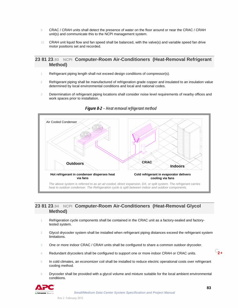
Small/Medium Data Center System Specification and Project Manual
83
Rev 2 February 2012
9 CRAC / CRAH units shall detect the presence of water on the floor around or near the CRAC / CRAH unit(s) and communicate this to the NCPI management system.
10 CRAH unit liquid flow and fan speed shall be balanced, with the valve(s) and variable speed fan drive motor positions set and recorded.
23 81 23.93 NCPI Computer-Room Air-Conditioners (Heat-Removal Refrigerant
Method)
1 Refrigerant piping length shall not exceed design conditions of compressor(s).
2 Refrigerant piping shall be manufactured of refrigeration grade copper and insulated to an insulation value determined by local environmental conditions and local and national codes.
3 Determination of refrigerant piping locations shall consider noise level requirements of nearby offices and work spaces prior to installation.
23 81 23.94 NCPI Computer-Room Air-Conditioners (Heat-Removal Glycol Method)
1 Refrigeration cycle components shall be contained in the CRAC unit as a factory-sealed and factory-tested system.
2 Glycol drycooler system shall be installed when refrigerant piping distances exceed the refrigerant system limitations.
3 One or more indoor CRAC / CRAH units shall be configured to share a common outdoor drycooler.
4 Redundant drycoolers shall be configured to support one or more indoor CRAH or CRAC units.
5 In cold climates, an economizer coil shall be installed to reduce electric operational costs over refrigerant cooling method.
6 Drycooler shall be provided with a glycol volume and mixture suitable for the local ambient environmental conditions.
Hot refrigerant in condenser disperses heat via fans
Cold refrigerant in evaporator delivers cooling via fans
The above system is referred to as an air-cooled, direct expansion, DX, or split system. The refrigerant carries heat to outdoor condenser. The Refrigeration cycle is split between indoor and outdoor components.
Air Cooled Condenser
CRAC Indoors Outdoors
C 2+
Figure 8-2 – Heat removal refrigerant method

Small/Medium Data Center System Specification and Project Manual
84
Rev 2 February 2012
Glycol carries heat from indoor condenser to outdoor fans
Complete refrigeration cycle is in the CRAC
23 81 23.95 NCPI Computer-Room Air-Conditioners (Heat-Removal Condenser
Water Method)
1 Refrigeration cycle components shall be contained in the CRAC unit as a factory-sealed and factory-tested system.
2 CRAC / CRAH units shall be configured to share a common cooling tower.
3 CRAC / CRAH units shall be configured to share redundant cooling towers.
4 In cold climates, a water coil shall be installed in the CRAC unit to reduce electric operational costs over refrigerant cooling method.
5 In cold climates, a cooling tower water loop shall utilize a heat exchanger to isolate the data center water loop from the building water loop to reduce electrical operational costs.
6 A multi-tenant building shall use a shared condenser water system as a sole source for data center cooling only when condenser water is provided 7x24x365 and sufficient condenser water treatment is accessible.
Complete refrigeration cycle is in the CRAC Water carries heat from indoor condenser to outdoor cooling tower
The above system is referred to as a condenser water system. The water carries heat outdoors to cooling tower. Refrigeration cycle is completely indoors.
The above system is referred to as a glycol-cooled system. The glycol fluid carries heat to outdoor the drycooler. Refrigeration cycle is completely indoors.
Cooling Tower
Outdoors Indoors Pump CRAC
Drycooler
CRAC Indoors Outdoors
C 3+
Figure 8-3 – Heat removal glycol method
Figure 8-4 – Heat removal condenser water method

Small/Medium Data Center System Specification and Project Manual
85
Rev 2 February 2012
Tab # 9 goes here

Small/Medium Data Center System Specification and Project Manual
86
Rev 2 February 2012
SSttaannddaarrdd SSyysstteemm SSppeecciiffiiccaattiioonn
9 Management
Division 25 – Integrated Automation
Containing specifications in these CSI divisions:
CCSSII 22000044 MMaasstteerrFFoorrmmaatt™

Small/Medium Data Center System Specification and Project Manual
87
Rev 2 February 2012
INTEGRATED AUTOMATION CSI Division 25 25 05 00.90 NCPI Common Work Results for Integrated Automation
(Management Systems)
1 The NCPI management system shall be modular and scalable to at least 1000 devices.
2 The NCPI management system shall monitor operating parameters of data center physical infrastructure elements.
3 The NCPI management system shall import the data center floor layout from a design and configuration tool.
4 The NCPI management system shall monitor devices on both the private and public LANs.
5 The NCPI management system shall monitor devices in both local and remote data centers.
6 The NCPI management system equipment provided and installed shall be new.
7 The NCPI management system shall monitor physical infrastructure elements including but not limited to the following:
a Uninterruptible power supplies (UPS)
b Power distribution units (PDU)
c Rack-level (“power-strip”) PDUs
d Air conditioning and air handling units
e Security and environmental data (temperature / humidity, vibration / water / smoke / fire, doors / motion / video)
f Automatic transfer switches (ATS)
g Standby generator
h Emergency power off (EPO)
8 The NCPI management system shall communicate over the data center’s existing network infrastructure.
9 The NCPI management system shall monitor rack level parameters including but not limited to the following:
a Temperature
b Humidity
c Rack security (door closure)
d Power load
10 The NCPI management system shall monitor data from dry contact points.
11 The NCPI management system shall monitor data from sensors, including temperature, humidity, motion, leak, and vibration.

Small/Medium Data Center System Specification and Project Manual
88
Rev 2 February 2012
25 08 00.90 NCPI Commissioning of Integrated Automation (Management Systems)
1 Owner / owner’s representative shall provide:
a Network configuration settings (IP addresses, subnet mask, network gateway addresses) necessary for managed physical infrastructure devices that reside on the owner’s / owner representative’s public network.
b E-mail addresses and SMTP settings for e-mail notification
c The network management workstation’s IP address and community string for SNMP trap notification from the NCPI management system server
25 11 13.90 NCPI Integrated Automation Network Servers (Management
Systems)
1 The NCPI management system shall operate from a centralized server, accessible remotely via Web browser.
2 The NCPI management system server shall use a single IP address to manage private-LAN devices through the user’s public network.
3 The NCPI management system server shall be rack mountable.
4 The centralized server designated for the NCPI management system shall allow remote management by the manufacturer (or other third party) 7x24x365.
5 The centralized management server shall support encryption to allow access control and integrity for SSL browser and SSH sessions.
6 The centralized management server shall support the use of an existing authentication and / or directory service (i.e. RADIUS, Active Directory, LDAP) for secure authentication and authorization of users.
7 The centralized management server shall allow for more than one level of management system access and control.
8 The centralized management server shall allow a minimum of 20 concurrent users of the management system.
9 The centralized management server shall support the IPMI standard for monitoring server hardware (i.e. fan speed, internal temperature, power supply status).
10 The NCPI management system server shall run the Linux operating system.
11 The management server’s user interface shall display data logs, alarms, and system messages and be accessible locally or remotely via a Web browser.
12 The NCPI management system server software shall be pre-installed and pre-tested by the manufacturer.
13 The NCPI management system server shall be locally accessible with a monitor and keyboard for field service diagnostic purposes.
14 The NCPI management system server shall send data to the BMS using Modbus protocol.
15 Thresholds for alarm notification in the NCPI management system shall be user-configurable.

Small/Medium Data Center System Specification and Project Manual
89
Rev 2 February 2012
16 The NCPI management system shall send data to the enterprise management system using SNMP trap forwarding over owner’s / owner representative’s network connection.
25 15 00.90 NCPI Integrated Automation Software (Management Systems)
1 The client workstation(s) used to access the NCPI management system server shall have an operating system and browser compatible with the NCPI management system server.
2 The NCPI management system shall integrate new devices with additional software licenses without custom programming.
25 15 00.92 NCPI Integrated Automation Software (Data Collection and Storage
for Management System)
1 Data shall export to file formats which include, but are not limited to the following:
a Excel
b HTML
c XML
d Text
2 The NCPI management system shall provide data trending and reporting for financial and operational planning.
3 The NCPI management system shall utilize network attached storage to increase physical infrastructure data storage capability.
4 The NCPI management system server shall store a minimum of 6 months of continuous data collection for trending validity purposes.
5 The server shall issue warnings when data stored exceeds 65% of system storage capacity.
6 Upon user request, the NCPI management system server shall automatically update firmware of managed devices.
7 The NCPI management system server shall allow mass configuration of managed devices.
8 Local displays on physical infrastructure elements (i.e. UPS, PDU, CRAC) shall have color-coded status indicators.

Small/Medium Data Center System Specification and Project Manual
90
Rev 2 February 2012
Tab # 10 goes here

Small/Medium Data Center System Specification and Project Manual
91
Rev 2 February 2012
SSttaannddaarrdd SSyysstteemm SSppeecciiffiiccaattiioonn
Fire Protection
10
Division 21 – Fire Suppression Division 28 – Electronic Safety and Security
CCSSII 22000044 MMaasstteerrFFoorrmmaatt™
Containing specifications in these CSI divisions:
FFiirree SSuupppprreessssiioonn HHeeaatt aanndd SSmmookkee DDeetteeccttiioonn

Small/Medium Data Center System Specification and Project Manual
92
Rev 2 February 2012
FIRE SUPPRESSION CSI Division 21
21 05 00.90 NCPI Common Work Results for Fire Suppression
1 Data center fire suppression and extinguishing systems shall notify fire department upon activation and trigger all general building fire alarms.
2 Data center fire suppression system shall communicate with BMS and NCPI management systems.
3 Data center fire suppression equipment shall be designed for 7x24x365 operation.
4 Data center fire suppression equipment provided and installed shall be new.
5 48-Hour battery backup (60-hour if no generator) shall be provided for fire suppression system.
21 08 00.90 NCPI Commissioning of Fire Suppression
1 Commissioning of fire suppression equipment shall conform to local and national fire codes.
2 Commissioning of fire suppression equipment shall be witnessed by the owner’s insurance carrier, and IT operations, facilities management and security personnel.
21 09 00.90 NCPI Instrumentation and Control for Fire-Suppression Systems
1 Data center fire suppression system and controls shall be independent of building fire suppression system and controls.
2 Data center fire suppression system shall appear as a single alarm point on the building’s main fire alarm panel.
3 General building fire alarm horn / strobe shall be installed in the data center and labeled as “Building Fire Alarm”.
21 09 00.92 NCPI Instrumentation and Control for Fire-Suppression Systems
(Audible Alarm Disable Switch)
1 Data center shall have an audible-alarm disable switch adjacent to the fire alarm control panel.
2 The audible-alarm disable switch shall be utilized during periods of known smoke or heat-producing maintenance work that might trigger a false alarm.
3 Actuation of audible-alarm disable switch shall send an alert to the security control center, data center fire alarm panel, general building alarm panel, and NCPI management system.
4 Actuation of audible-alarm disable switch shall not prevent manual activation of a second stage alarm.

Small/Medium Data Center System Specification and Project Manual
93
Rev 2 February 2012
21 10 00.90 NCPI Water-Based Fire-Suppression Systems
1 Sprinkler system shall conform to local and national fire codes.
2 All sprinkler system plans and calculations shall be submitted to the authority having jurisdiction (AHJ) for review and approval prior to installation.
3 The following sprinkler system controls shall be included in fire alarm control panel:
a Water flow switch
b PIV (post indicator valve) tamper switch
4 In data centers with no suspended (drop) ceiling, sprinklers shall be configured upright.
5 In data centers where suspended (drop) ceiling is present, sprinkler heads shall be of the concealed type.
6 All sprinkler system shutoff valves shall be of the OS&Y (open stem and yoke) type.
7 Water flow switch shall activate EPO system.
21 13 19.90 NCPI Preaction Sprinkler Systems
1 Sprinkler system shall be preaction type which shall not allow water to enter the sprinkler piping during an accidental breakage of a sprinkler head.
2 Sprinkler system shall be double-acting preaction type which shall combine preaction and smoke detection.
3 Sprinkler actuation system shall be armed by the initiation of an alarm from a cross-zoned detection system.
4 Sprinkler system design density shall conform to the owner’s / owner representative’s insurance company, lease agreement fire protection requirements, and local and national codes.
5 All sprinkler system plans and calculations shall be submitted to the authority having jurisdiction (AHJ) for review and approval prior to installation.
6 The following sprinkler system controls shall be included in fire alarm control panel:
a water flow switch
b PIV (post indicator valve) tamper switch
c sprinkler piping supervisory air pressure switch
7 In data centers with no suspended (drop) ceiling, sprinklers shall be configured upright.
8 In data centers where suspended (drop) ceiling is present, sprinkler heads shall be of the concealed type.
9 Dry pendant sprinkler heads shall not be used in the data center.
10 All sprinkler system shutoff valves shall be of the OS&Y (open stem and yoke) type.
11 Data center shall have a preaction sprinkler disable switch located adjacent to the preaction control panel.
C 2+
C 2+

Small/Medium Data Center System Specification and Project Manual
94
Rev 2 February 2012
12 Preaction sprinkler disable switch shall be key-actuated (on / off) external to the main control panel.
13 Smoke detection system shall remain in service upon actuation of the preaction sprinkler disable switch
14 A preaction sprinkler disable switch shall be utilized to prevent the triggering of preaction sprinkler during periods of known smoke or heat-producing maintenance work that might trigger a false alarm.
15 Actuation of preaction sprinkler disable switch shall send an alert signal to the security control center, data center fire alarm panel, general building alarm panel, and NCPI management system.
16 Actuation of preaction sprinkler disable switch shall not prevent manual activation of a second stage alarm.
21 13 19.92 NCPI Preaction Sprinkler Systems (Sprinkler Piping)
1 All preaction sprinkler piping shall be pitched toward the sprinkler riser.
2 Low point drains shall be provided where sprinkler pipes cannot be fully drained back to the riser.
3 All sprinkler piping shall be of type and schedule approved for installation as per local and national code requirements.
4 Installation of preaction sprinkler system piping and valves shall be listed by recognized standards organizations and approved by insurance-carrier.
5 Sprinkler system pipes shall be schedule 40 or local equivalent pipe, listed by recognized standards organizations and approved by insurance-carrier.
6 End piping shall be groove jointed end.
7 End piping shall be threaded.
8 A purging valve shall be provided with drainage to a location outside of the data center.
21 22 00.90 NCPI Clean-Agent Fire-Extinguishing Systems
1 The data center shall have a clean agent fire extinguishing system installed.
2 “Clean agents” shall include, but are not limited to, the following:
a Halon
b FM-200
c FE13
d FE227
e Inergen
f Novec
3 Clean agent fire extinguishing system shall be designed and installed to conform to local and national codes.
4 Clean agent fire extinguishing system shall be activated either by the initiation of any two cross-zoned ionization and photoelectric smoke detectors or by manually activated pull station.
C 4
C 3+ C 3+
C 3+

Small/Medium Data Center System Specification and Project Manual
95
Rev 2 February 2012
5 For data centers with raised floor, the fire extinguishing system shall extinguish a fire beneath the raised access flooring.
6 For data centers with ceiling plenum, the fire extinguishing system shall be designed to extinguish a fire within the data center ceiling plenum.
7 The fire extinguishing system shall incorporate a push-and-hold button at each data center exit to prevent discharge during a false alarm.
8 The fire extinguishing operation and reset procedures shall be posted adjacent to clean agent alarm control panel.
9 The fire extinguishing system shall communicate with BMS, building fire alarm system, and NCPI management system.
10 Upon discharge of the clean agent, the EPO system shall be automatically activated.
11 With clean agent fire extinguishing systems, data center ceiling tiles shall be clamped to ceiling support structure to keep tiles in place during clean agent discharge.
12 During clean agent fire extinguishing system installation, the data center’s air volume and air pressure shall be tested to determine whether area of wall penetration openings does not exceed design limits.
13 When the clean agent used is Inergen, a mechanical pressure-relieving wall or ceiling shall be installed to relieve over-pressuring of the room during clean agent discharge.
14 When the clean agent used is FM-200 or a derivative, the data center shall be equipped with a separately switched and powered exhaust duct, both above and below the raised floor.
15 When the clean agent used is FM-200 or a derivative, the exhaust duct shall exhaust directly to the outside of the building.
16 Clean agent fire extinguishing system shall have a manually activated redundant tank (second shot) since clean agent systems are single shot designs.
17 Clean agent fire-extinguishing system shall be of the automatic single shot system type with a water-based fire-suppression system back-up (double-acting preaction).
21 22 16.90 NCPI Clean-Agent Fire-Extinguishing Equipment (Hand Held)
1 Hand held fire extinguishers shall be an A-B-C rated clean-agent, listed by recognized standards organizations and approved by insurance-carrier.
2 One hand held fire extinguisher shall be located at each data center entrance.
3 Hand held fire extinguishers shall be positioned at intervals of at most 50 ft (15 m).
4 The data center shall have a minimum of two hand held fire extinguishers.
5 The data center shall have at least one hand held fire extinguishers for every 600 ft2 (55.7 m2) of data center floor space.
6 Hand held fire extinguishers shall be clearly marked as fire extinguishing equipment.
C 3+
C 3+
C 3+ C 3+ C 3+
C 3+
C 3+
C 3+
C 3+
C 4
C 4
C 3+
C 3+

Small/Medium Data Center System Specification and Project Manual
96
Rev 2 February 2012
ELECTRONIC SAFETY AND SECURITY CSI Division 28 28 31 46. 90 NCPI Smoke Detection Sensors (Photoelectric / Ionization)
1 Smoke detector system shall consist of cross-zone activation with photoelectric / ionization detectors.
2 Each smoke detector shall be labeled and numbered.
3 Each smoke detector shall be addressable by the fire alarm panel.
4 A graphical interface shall be provided, indicating smoke detector address and data center floor plan location.
5 48-hour battery backup shall be provided for smoke detection system; 60-hour battery backup when no generator exists.
28 31 46.92 NCPI Smoke Detection Sensors (Heat Detection)
1 Heat detection sensors shall be located where smoke detectors will trigger false alarms (i.e. printing environments or high speed air).
28 31 46.94 NCPI Smoke Detection Sensors (High Sensitivity Smoke Detection
System)
1 HSSD early warning system, independent of preaction sprinkler system, shall be installed in the data center.
2 HSSD early warning system shall be installed as an alarm-only system (will not activate fire suppression or extinguishing system).
3 HSSD early warning air sampling zones shall be located at the ceiling level and the air conditioner intakes.
4 HSSD early warning air sampling zones shall be located below the raised access floor.
5 HSSD early warning system shall not be used to trigger any EPO functions.
6 HSSD early warning system shall alarm to NCPI monitoring system and BMS.
C 3+
C 3+ C 3+
C 3+ C 3+ C 3+

Small/Medium Data Center System Specification and Project Manual
97
Rev 2 February 2012
Tab # 11 goes here

Small/Medium Data Center System Specification and Project Manual
98
Rev 2 February 2012
SSttaannddaarrdd SSyysstteemm SSppeecciiffiiccaattiioonn
Physical Security
11
Division 28 – Electronic Safety and Security
CCSSII 22000044 MMaasstteerrFFoorrmmaatt™
Containing specifications in these CSI divisions:
AAcccceessss CCoonnttrrooll VViiddeeoo SSuurrvveeiillllaannccee

Small/Medium Data Center System Specification and Project Manual
99
Rev 2 February 2012
ELECTRONIC SAFETY AND SECURITY CSI Division 28 28 05 00.90 NCPI Common Work Results for Electronic Safety and Security
1 Data center electronic safety and security equipment shall communicate with BMS and NCPI management systems.
2 Data center electronic safety and security equipment shall monitor and control rack access.
3 Data center electronic safety and security equipment provided and installed shall be new.
28 13 23.90 NCPI Access Control Remote Devices
1 Building and data center entrances shall be controlled via card access control system.
2 Data center entrances shall detect and communicate when a door(s) is propped open for a pre-programmed period of time.
3 Electronic door locks shall default to the unlocked position during a power interruption or EPO operation.
4 IT rack doors shall be equipped with access control system as specified in section 6, “Racks”, CSI Division 27, “Communications”, CSI number 27 11 16.90
28 23 00.90 NCPI Video Surveillance
1 Data center exterior walls, roof areas, and adjoining parking areas shall be monitored by pan, track, and zoom low-light cameras.
2 Building and data center entrances shall be equipped with digitally recorded network-based security color camera technology, monitored by the security personnel.
3 EPO switches shall be monitored by digitally recorded network-based security color camera technology.
4 Video surveillance system shall send alarms to NCPI management system

Small/Medium Data Center System Specification and Project Manual
100
Rev 2 February 2012
Tab # 12 goes here

Small/Medium Data Center System Specification and Project Manual
101
Rev 2 February 2012
AAccrroonnyymmss GGlloossssaarryy AAppppeennddiixx AA MMaasstteerrFFoorrmmaatt 11999955 aanndd MMaasstteerrFFoorrmmaatt 22000044 CCrroossss RReeffeerreennccee AAppppeennddiixx BB MMaasstteerrFFoorrmmaatt DDiivviissiioonnss LLiinnkkeedd ttoo TTrraaddeess IINNDDEEXX
REFERENCE 12

Small/Medium Data Center System Specification and Project Manual
102
Rev 2 February 2012
01 42 13.90 NCPI Abbreviations and Acronyms
AHJ authority having jurisdiction
ANSI American National Standards Institute
ARI Air Conditioning and Refrigeration Institute
ASHRAE American Society of Heating, Refrigeration and Air Conditioning Engineers
ASME American Society of Mechanical Engineers
ASTM American Society for Testing Materials
ATS automatic transfer switch
AWG American wire gauge
BGS building grounding system
BICSI Building Industry Consulting Service International
BMS building management system
CCTV closed circuit television
CFD computational fluid dynamics
CRAC data center air conditioner
CRAH data center air handler
CSA Canadian Standards Association
CW chilled water
DX direct expansion
EMI electromagnetic interference
EMS enterprise management system
EPO emergency power off (officially referred to as “disconnecting means”)
ETL Edison testing laboratory (formerly)
GFI ground fault interruption
HEPA high efficiency particulate air (filter)
HSSD high sensitivity smoke detection
HVAC heating ventilation air conditioning
IPMI intelligent platform management interface
ISO International Standards Organization
IT information technology
LSS life safety system
MBC maintenance bypass cabinet
MBP maintenance bypass panel
NCPI network-critical physical infrastructure
NEC National Electrical Code
NECA National Electrical Contractors Association
NEMA National Electric Manufacturer's Association
NFPA National Fire Protection Agency

Small/Medium Data Center System Specification and Project Manual
103
Rev 2 February 2012
NOC network operations center
NRTL National Recognized Testing Laboratory
NTC Negative Temperature Coefficient
OS&Y open stem and yoke (preaction system)
PAC precision air conditioner
PDU power distribution unit
PMG permanent magnet generator
RADIUS remote authentication dial in user service
RFI radio frequency interference
RH relative humidity
RMS root mean square
SDS separately derived source
SNMP serial network management protocol
SPG single point ground
SPOF single point of failure
SRG signal reference ground grid (IEEE 1100)
SSH secure shell
SSL secure sockets layer
TIA telecommunications industry association
TCP/IP Transmission Control Protocol/Internet Protocol
TVSS transient-voltage surge suppression
UL Underwriters Laboratory
UPS uninterruptible power supply
VAV variable air volume
VCT vinyl composition tile
VESDA very early smoke detection apparatus
VPC volts per cell
VRLA valve regulated lead acid

Small/Medium Data Center System Specification and Project Manual
104
Rev 2 February 2012
01 42 16.90 NCPI Definitions
access floor A system consisting of completely removable and interchangeable floor panels that are
supported on adjustable pedestals or stringers (or both) to allow access to the area beneath.
availability The degree to which a system or component is operational and accessible when
required for use closet (See wiring closet.) criticality level A system of data center reliability measurements / and designs that categorize data
centers. data center A building or portion of a building whose primary function is to accommodate data
processing equipment and its support areas. island redundancy Used within the boundaries of a multiple tenanted data center, where mission critical
racks requiring redundant power, cooling and network infrastructure are colocated with racks not requiring high levels of redundancy, such as administrative or informational data base systems. Also referred to as targeted redundancy.
large data center A facility supporting 100 or more racks of IT equipment. NCPI Network-critical physical infrastructure (NCPI) is the foundation upon which information
technology (IT) and telecommunication networks reside. This includes: power; cooling; racks & physical structure; security & fire protection; cabling; management systems; and service.
NCPI management Centralized management (includes monitoring and control) of network-critical physical
infrastructure (NCPI) devices in data center and distributed network environments. redundancy (N, N+1, 2N etc) Reliability designs are described by nomenclatures using the letter "N". "N" is simply
defined as the "need" of the critical load, or the capacity required of the support infrastructure to fully support the critical load. An example of the use of the term "N" is used in describing a parallel redundant UPS system (two equal-sized UPSs connected to a common output), which may be called an "N+1" design, or a facility using dual, totally independent electrical and mechanical infrastructure pathways may be referred as a "2N" system.
server room A room supporting from 1 to 5 racks of equipment. small / medium data center A facility supporting a data center containing from 5 to 100 racks of IT equipment. telecommunications room (See wiring closet.) tier A system of data center reliability measurements / and designs that categorize data
centers. wiring closet (Also IDF and wiring closet.) A room supporting from 1 to 3 racks of equipment

Small/Medium Data Center System Specification and Project Manual
105
Rev 2 February 2012
MasterFormat 1995 and MasterFormat 2004 Cross Reference
1995 Edition MasterFormat 2004 Edition MasterFormat *95 SECTION 95 TITLE 95 LEVEL 04 SECTION 04 TITLE 04 LEVEL
01420 Abbreviations and Acronyms 4 01 42 13 Abbreviations and Acronyms 301420 Definitions 4 01 42 16 Definitions 301420 Reference Standards 4 01 42 19 Reference Standards 301640 Owner-Furnished Products 3 01 64 00 Owner-Furnished Products 201780 Operation Data 4 01 78 23.13 Operation Data 401780 Maintenance Data 4 01 78 23.16 Maintenance Data 401780 Product Warranties 4 01 78 36 Warranties 301780 Project Record Documents 4 01 78 39 Project Record Documents 301780 Spare Parts 4 01 78 43 Spare Parts 301810 Commissioning Summary 4 01 91 13 General Commissioning Requirements 301820 Demonstration and Training 3 01 79 00 Demonstration and Training 201830 Operation and Maintenance 3 01 92 13 Facility Operation Procedures 301830 Operation and Maintenance 3 01 93 13 Facility Maintenance Procedures 307210 Building Insulation 3 07 21 00 Thermal Insulation 207840 Firestopping 3 07 84 00 Firestopping 207840 Intumescent Firestopping Foams 4 07 84 00 Firestopping 2
07840 Through Penetration Firestopping Pillows
4 07 84 00 Firestopping 2
09050 BASIC FINISH MATERIALS AND METHODS
2 09 05 00 Common Work Results for Finishes 2
09650 Resilient Flooring 3 09 65 00 Resilient Flooring 209660 Static Control Flooring 3 09 65 36 Static-Control Resilient Flooring 309910 Interior Paints 4 09 91 23 Interior Painting 309980 Coatings for Concrete and Masonry 3 09 97 23 Concrete and Masonry Coatings 3
10270 Rigid Grid Access Flooring 4 09 69 13 Rigid-Grid Access Flooring 313100 LIGHTNING PROTECTION 2 26 41 00 Facility Lightning Protection 213410 Optical Fiber Cable 4 27 13 23 Communications Optical Fiber Backbone
Cabling3
13410 Optical Fiber Cable 4 27 15 23 Communications Optical Fiber Horizontal Cabling
3
13700 Door Answering 4 28 13 00 Access Control 213700 SECURITY ACCESS AND
SURVEILLANCE 2 28 20 00 Electronic Surveillance 2
13700 Video Surveillance 4 28 23 00 Video Surveillance 213850 Smoke Alarm 4 28 31 46 Smoke Detection Sensors 313940 Pre-Action Fire Suppression
Sprinklers3 21 13 19 Preaction Sprinkler Systems 3
13965 Alternative Fire Extinguishing Systems
3 21 22 00 Clean-Agent Fire-Extinguishing Systems 2
13965 Halon Alternative 4 21 22 00 Clean-Agent Fire-Extinguishing Systems 2

Small/Medium Data Center System Specification and Project Manual
106
Rev 2 February 2012
1995 Edition MasterFormat 2004 Edition MasterFormat *95 SECTION 95 TITLE 95 LEVEL 04 SECTION 04 TITLE 04 LEVEL
15050 BASIC MECHANICAL MATERIALS AND METHODS
2 22 05 00 Common Work Results for Plumbing 2
15050 BASIC MECHANICAL MATERIALS AND METHODS
2 23 05 00 Common Work Results for HVAC 2
15130 Pumps 3 23 21 23 Hydronic Pumps 315180 Hydronic Piping 4 23 21 13 Hydronic Piping 315180 Heating and Cooling Pumps 4 23 21 23 Hydronic Pumps 315810 Metal Ducts 4 23 31 13 Metal Ducts 316050 BASIC ELECTRICAL MATERIALS
AND METHODS2 26 05 00 Common Work Results for Electrical 2
16060 Grounding and Bonding 3 26 05 26 Grounding and Bonding for Electrical Systems
3
16075 Electrical Identification 3 26 05 53 Identification for Electrical Systems 316100 WIRING METHODS 2 26 05 00 Common Work Results for Electrical 216120 Conductors and Cables 3 26 05 19 Low-Voltage Electrical Power Conductors
and Cables3
16140 Floor Boxes 4 26 27 26 Wiring Devices 316140 Receptacles 4 26 27 26 Wiring Devices 316140 Remote-Control Switching Devices 4 26 27 26 Wiring Devices 3
16140 Wall Plates 4 26 27 26 Wiring Devices 316140 Wall Switches and Dimmers 4 26 27 26 Wiring Devices 316140 Wiring Devices 3 26 27 26 Wiring Devices 316150 Wiring Connections 3 26 05 00 Common Work Results for Electrical 216220 Motors and Generators 3 26 05 00 Common Work Results for Electrical 216230 Motor Generators 4 26 05 00 Common Work Results for Electrical 216230 Engine Generators 4 26 32 13 Engine Generators 316240 Battery Equipment 3 26 33 00 Battery Equipment 216240 Batteries 4 26 33 13 Batteries 316260 Direct Current (DC) Drive
Controllers4 26 33 00 Battery Equipment 2
16260 Static Uninterruptible Power Supplies
4 26 33 53 Static Uninterruptible Power Supply 3
16270 Distribution Transformers 4 26 22 13 Low-Voltage Distribution Transformers 316290 Power Measurement and Control 3 26 09 13 Electrical Power Monitoring and Control 3
16430 Low-Voltage Switchgear 3 26 23 00 Low-Voltage Switchgear 216440 Switchboards, Panelboards, and
Control Centers3 26 24 00 Switchboards and Panelboards 2
16470 Power Distribution Units 3 26 26 00 Power Distribution Units 216510 Interior Luminaires 3 26 51 00 Interior Lighting 216720 Telephone and Intercommunication
Equipment3 27 30 00 Voice Communications 2

Small/Medium Data Center System Specification and Project Manual
107
Rev 2 February 2012
MasterFormat Divisions Linked to Trades CSI Division
Trade
Division 00 Owner, Engineering, Architecture Procurement and Contracting Division 01 Owner and All Trades General Requirements Division 07 Carpentry Thermal and Moisture Protection Division 09 Carpentry Finishes Division 13 Carpentry Special Construction Division 21 Pipe Fitting Fire Suppression Division 22 Plumbing Plumbing Division 23 Mechanical HVAC Division 25 Electrical Integrated Automation Division 26 Electrical Electrical Division 27 Electrical Communications Division 28 Electrical Electronic Safety and Security

Small/Medium Data Center System Specification and Project Manual
108
Rev 2 February 2012
Alphabetical index will be included in a future revision of this book.