voltage sensing module 10 (vsm10)voltage sensing module 10 (vsm10) operating instructions, 05/2010,...
TRANSCRIPT

Operating Instructions · 05/2010
Voltage Sensing Module 10 (VSM10)
SINAMICS G130
SINAMICS
s


�Voltage Sensing Module 10 (VSM10)�
___________________
___________________
___________________
___________________
___________________
SINAMICS
SINAMICS G130 Voltage Sensing Module 10 (VSM10)
Operating Instructions
Control version V4.3 SP2
05/2010 A5E02142235A
Safety information 1
General
2
Mechanical installation
3
Electrical installation
4
Technical specifications
5

Legal information
Legal information Warning notice system
This manual contains notices you have to observe in order to ensure your personal safety, as well as to prevent damage to property. The notices referring to your personal safety are highlighted in the manual by a safety alert symbol, notices referring only to property damage have no safety alert symbol. These notices shown below are graded according to the degree of danger.
DANGER indicates that death or severe personal injury will result if proper precautions are not taken.
WARNING indicates that death or severe personal injury may result if proper precautions are not taken.
CAUTION with a safety alert symbol, indicates that minor personal injury can result if proper precautions are not taken.
CAUTION without a safety alert symbol, indicates that property damage can result if proper precautions are not taken.
NOTICE indicates that an unintended result or situation can occur if the corresponding information is not taken into account.
If more than one degree of danger is present, the warning notice representing the highest degree of danger will be used. A notice warning of injury to persons with a safety alert symbol may also include a warning relating to property damage.
Qualified Personnel The product/system described in this documentation may be operated only by personnel qualified for the specific task in accordance with the relevant documentation for the specific task, in particular its warning notices and safety instructions. Qualified personnel are those who, based on their training and experience, are capable of identifying risks and avoiding potential hazards when working with these products/systems.
Proper use of Siemens products Note the following:
WARNING Siemens products may only be used for the applications described in the catalog and in the relevant technical documentation. If products and components from other manufacturers are used, these must be recommended or approved by Siemens. Proper transport, storage, installation, assembly, commissioning, operation and maintenance are required to ensure that the products operate safely and without any problems. The permissible ambient conditions must be adhered to. The information in the relevant documentation must be observed.
Trademarks All names identified by ® are registered trademarks of the Siemens AG. The remaining trademarks in this publication may be trademarks whose use by third parties for their own purposes could violate the rights of the owner.
Disclaimer of Liability We have reviewed the contents of this publication to ensure consistency with the hardware and software described. Since variance cannot be precluded entirely, we cannot guarantee full consistency. However, the information in this publication is reviewed regularly and any necessary corrections are included in subsequent editions.
Siemens AG Industry Sector Postfach 48 48 90026 NÜRNBERG GERMANY
A5E02142235A Ⓟ 08/2010
Copyright © Siemens AG 2010. Technical data subject to change

Voltage Sensing Module 10 (VSM10) Operating Instructions, 05/2010, A5E02142235A 5
Table of contents
1 Safety information...................................................................................................................................... 7
1.1 Warnings ........................................................................................................................................7 1.2 Safety and operating instructions...................................................................................................8 1.3 Components that can be destroyed by electrostatic discharge (ESD) ..........................................9
2 General.................................................................................................................................................... 11 2.1 Safety information ........................................................................................................................11
3 Mechanical installation............................................................................................................................. 13 4 Electrical installation ................................................................................................................................ 15
4.1 Overview ......................................................................................................................................15 4.2 Connection diagram.....................................................................................................................16 4.3 Interface description.....................................................................................................................17 4.3.1 Electronics power supply X524....................................................................................................17 4.3.2 DRIVE-CLiQ interface X500 ........................................................................................................18 4.3.3 X520 analog inputs/temperature sensor......................................................................................18 4.3.4 X521 three-phase line supply voltage sensing up to 100 V (phase-to-phase) ............................19 4.3.5 X522 three-phase line supply voltage sensing up to 690 V (phase-to-phase) ............................19 4.3.6 Significance of the LEDs for the Voltage Sensing Module VSM10 .............................................20
5 Technical specifications........................................................................................................................... 21

Table of contents
Voltage Sensing Module 10 (VSM10) 6 Operating Instructions, 05/2010, A5E02142235A

Voltage Sensing Module 10 (VSM10) Operating Instructions, 05/2010, A5E02142235A 7
Safety information 11.1 Warnings
WARNING
Hazardous voltages are present when electrical equipment is in operation. Severe personal injury or substantial material damage may result if these warnings are not observed. Only qualified personnel are permitted to work on or around the equipment. This personnel must be thoroughly familiar with all the warnings and maintenance procedures described in these operating instructions. The successful and safe operation of this device is dependent on correct transport, proper storage and installation, as well as careful operation and maintenance. National safety guidelines must be observed.
DANGER
Five safety rules When carrying out any kind of work on electrical devices, the "five safety rules" defined in EN 50110 must always be observed: 1. Disconnect the system. 2. Protect against reconnection. 3. Make sure that the equipment is de-energized. 4. Ground and short-circuit. 5. Cover or enclose adjacent components that are still live.
NOTICE For a UL-approved system use 60/75°C copper conductors only.
Safety information 1.2 Safety and operating instructions
Voltage Sensing Module 10 (VSM10) 8 Operating Instructions, 05/2010, A5E02142235A
1.2 Safety and operating instructions
DANGER
This equipment is used in industrial high-voltage installations. During operation, this equipment contains rotating and live, bare parts. For this reason, they could cause severe injury or significant material damage if the required covers are removed, if they are used or operated incorrectly, or have not been properly maintained. When the machines are used in non-industrial areas, the installation location must be protected against unauthorized access (protective fencing, appropriate signs).
Prerequisites Those responsible for protecting the plant must ensure the following: ● The basic planning work for the plant and the transport, assembly, installation,
commissioning, maintenance, and repair work is carried out by qualified personnel and/or checked by experts responsible.
● The operating manual and machine documentation are always available. ● The technical specifications regarding the applicable installation, connection,
environmental, and operating conditions are always observed. ● The plant-specific assembly and safety guidelines are observed and personal protection
equipment is used. ● Unqualified personnel are forbidden from using these machines and working near them. This operating manual is intended for qualified personnel and only contain information and notes relating to the intended purpose of the machines. The operating manual and machine documentation are written in different languages as specified in the delivery contracts.
Note We recommend engaging the support and services of your local Siemens service center for all planning, installation, commissioning and maintenance work.
Safety information 1.3 Components that can be destroyed by electrostatic discharge (ESD)
Voltage Sensing Module 10 (VSM10) Operating Instructions, 05/2010, A5E02142235A 9
1.3 Components that can be destroyed by electrostatic discharge (ESD)
CAUTION The board contains components that can be destroyed by electrostatic discharge. These components can be easily destroyed if not handled properly. If you do have to use electronic boards, however, please observe the following: You should only touch electronic boards if absolutely necessary. When you touch boards, however, your body must be electrically discharged
beforehand. Boards must not come into contact with highly insulating materials (such as plastic
parts, insulated desktops, articles of clothing manufactured from man-made fibers). Boards must only be placed on conductive surfaces. Boards and components should only be stored and transported in conductive packaging
(such as metalized plastic boxes or metal containers). If the packaging material is not conductive, the boards must be wrapped with a
conductive packaging material (such as conductive foam rubber or household aluminum foil).
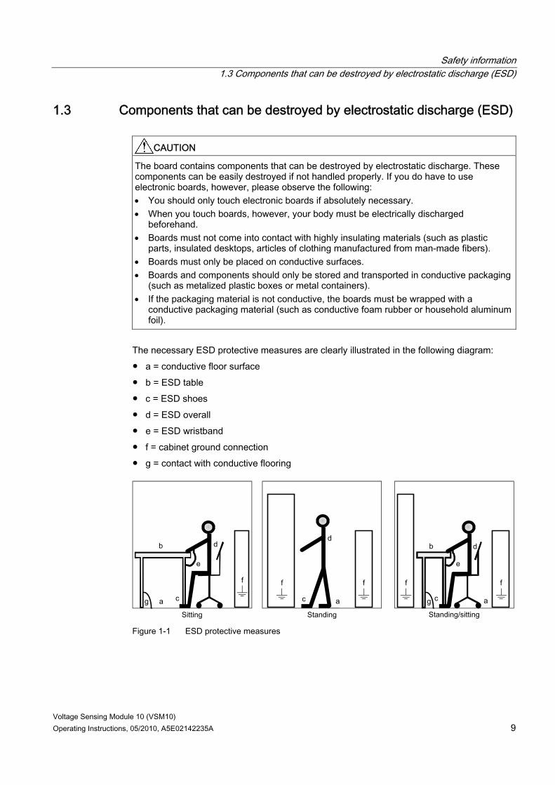
The necessary ESD protective measures are clearly illustrated in the following diagram: ● a = conductive floor surface ● b = ESD table ● c = ESD shoes ● d = ESD overall ● e = ESD wristband ● f = cabinet ground connection ● g = contact with conductive flooring
g g a
b
e
d
c
d
a c
d b
c a
e
f f f f f
Figure 1-1 ESD protective measures

Safety information 1.3 Components that can be destroyed by electrostatic discharge (ESD)
Voltage Sensing Module 10 (VSM10) 10 Operating Instructions, 05/2010, A5E02142235A
Voltage Sensing Module 10 (VSM10) Operating Instructions, 05/2010, A5E02142235A 11
General 2
The Voltage Sensing Module VSM10 is used to operate a permanent-magnet synchronous machine without encoder with the requirement for switching to a machine which is already running (flying restart function). To commission the function, the permanent-field synchronous machine without encoder must be input and "Flying restart" activated with p1200.
2.1 Safety information
WARNING The 50 mm clearances above and below the components must be observed.
NOTICE The VSM10 has two terminal blocks to sense the three-phase line supply voltage (X521 and X522). The voltage strength of terminal X521 is a maximum of 100 V (phase-to-phase) and is used for voltage sensing via a potential transformer. A maximum voltage to be sensed of up to to 690 V (phase-to-phase) can be directly connected to terminal X522. Only one of the two terminals X521 and X522 may be used. Nothing may be connected to the unused terminal.
CAUTION Connecting cables to temperature sensors must always be installed with shielding. The cable shield must be connected to the chassis potential at both ends through a large surface area. Temperature sensor cables that are routed together with the motor cable must be twisted in pairs and shielded separately.

General 2.1 Safety information
Voltage Sensing Module 10 (VSM10) 12 Operating Instructions, 05/2010, A5E02142235A

Voltage Sensing Module 10 (VSM10) Operating Instructions, 05/2010, A5E02142235A 13
Mechanical installation 3
Figure 3-1 Dimension drawing of Voltage Sensing Module VSM10
Note The VSM10 is installed near the Power Module on a mounting rail which must be provided by the customer.

Mechanical installation
Voltage Sensing Module 10 (VSM10) 14 Operating Instructions, 05/2010, A5E02142235A

Voltage Sensing Module 10 (VSM10) Operating Instructions, 05/2010, A5E02142235A 15
Electrical installation 44.1 Overview
Figure 4-1 Voltage Sensing Module VSM10

Electrical installation 4.2 Connection diagram
Voltage Sensing Module 10 (VSM10) 16 Operating Instructions, 05/2010, A5E02142235A
4.2 Connection diagram
Figure 4-2 Connection example VSM10 for operation of a permanent-magnet synchronous machine
without encoder
CAUTION The voltages for the cable to terminal -X522 must be taken downstream of an optional reactor or dv/dt filter, where possible directly at the motor connection terminals.
Electrical installation 4.3 Interface description
Voltage Sensing Module 10 (VSM10) Operating Instructions, 05/2010, A5E02142235A 17
CAUTION The cable for the -X522 connection must be routed to prevent short-circuiting and ground faults in accordance with IEC 61800-5-2:2007, Table D.1. This can be accomplished, for example, by: Eliminating the risk of mechanical damage to the cables Using cables with double insulation Maintaining adequate clearance, using spacers, for example Routing the cables in separate cable ducts or tubes
4.3 Interface description
4.3.1 Electronics power supply X524
Table 4- 1 Terminals for the electronics power supply
Terminal Designation Technical specifications + Electronics power supply + Electronics power supply M Electronics ground
M Electronics ground
Voltage: 24 V DC (20.4 V – 28.8 V) Current consumption: max. 0.2 A Max. current via jumper in connector: 20 A at 55 °C
Max. connectable cross-section: 2.5 mm²
Note The two "+" and "M" terminals are jumpered in the connector. This ensures that the supply voltage is looped through.
Electrical installation 4.3 Interface description
Voltage Sensing Module 10 (VSM10) 18 Operating Instructions, 05/2010, A5E02142235A
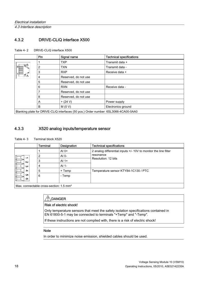
4.3.2 DRIVE-CLiQ interface X500
Table 4- 2 DRIVE-CLiQ interface X500
Pin Signal name Technical specifications 1 TXP Transmit data + 2 TXN Transmit data - 3 RXP Receive data + 4 Reserved, do not use 5 Reserved, do not use 6 RXN Receive data - 7 Reserved, do not use 8 Reserved, do not use A + (24 V) Power supply
B M (0 V) Electronics ground Blanking plate for DRIVE-CLiQ interfaces (50 pcs.) Order number: 6SL3066-4CA00-0AA0
4.3.3 X520 analog inputs/temperature sensor
Table 4- 3 Terminal block X520
Terminal Designation Technical specifications 1 AI 0+ 2 AI 0- 3 AI 1+ 4 AI 1-
2 analog differential inputs +/- 10V to monitor the line filter resonance Resolution: 12 bits
5 + Temp
6 - Temp
Temperature sensor KTY84-1C130 / PTC
Max. connectable cross-section: 1.5 mm²
DANGER Risk of electric shock! Only temperature sensors that meet the safety isolation specifications contained in EN 61800-5-1 may be connected to terminals "+Temp" and "-Temp". If these instructions are not complied with, there is a risk of electric shock!
Note In order to minimize noise emission, shielded cables should be used.

Electrical installation 4.3 Interface description
Voltage Sensing Module 10 (VSM10) Operating Instructions, 05/2010, A5E02142235A 19
CAUTION The common mode range must not be violated. This means that the analog differential voltage signals can have a maximum offset voltage of +/-30 V with respect to the ground potential. If the range is infringed, incorrect results may occur during analog/digital conversion.
4.3.4 X521 three-phase line supply voltage sensing up to 100 V (phase-to-phase) This interface is not relevant for SINAMICS G130.
4.3.5 X522 three-phase line supply voltage sensing up to 690 V (phase-to-phase)
Table 4- 4 Terminal block X522
Terminal Designation Technical specifications 1 Phase voltage U 2 Phase voltage V
3 Phase voltage W
Directly connected to sense the line supply voltage
Max. connectable cross-section: 6 mm²
NOTICE Only one of the two terminals X521 and X522 may be used. Nothing may be connected to the unused terminal.
NOTICE The phases must be connected to the VSM10 with the same sequence as that of the Power Module.
Electrical installation 4.3 Interface description
Voltage Sensing Module 10 (VSM10) 20 Operating Instructions, 05/2010, A5E02142235A
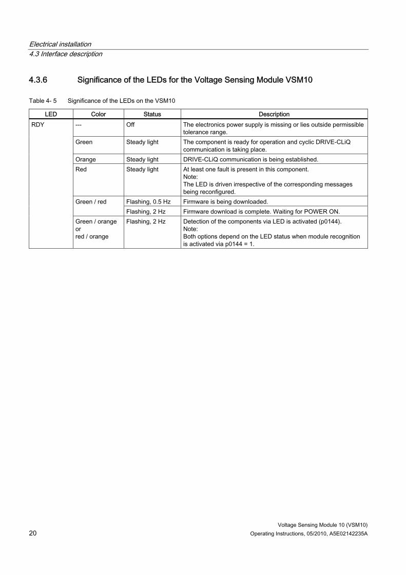
4.3.6 Significance of the LEDs for the Voltage Sensing Module VSM10
Table 4- 5 Significance of the LEDs on the VSM10
LED Color Status Description --- Off The electronics power supply is missing or lies outside permissible
tolerance range. Green Steady light The component is ready for operation and cyclic DRIVE-CLiQ
communication is taking place. Orange Steady light DRIVE-CLiQ communication is being established. Red Steady light At least one fault is present in this component.
Note: The LED is driven irrespective of the corresponding messages being reconfigured.
Flashing, 0.5 Hz Firmware is being downloaded. Green / red Flashing, 2 Hz Firmware download is complete. Waiting for POWER ON.
RDY
Green / orange or red / orange
Flashing, 2 Hz Detection of the components via LED is activated (p0144). Note: Both options depend on the LED status when module recognition is activated via p0144 = 1.
Voltage Sensing Module 10 (VSM10) Operating Instructions, 05/2010, A5E02142235A 21
Technical specifications 5
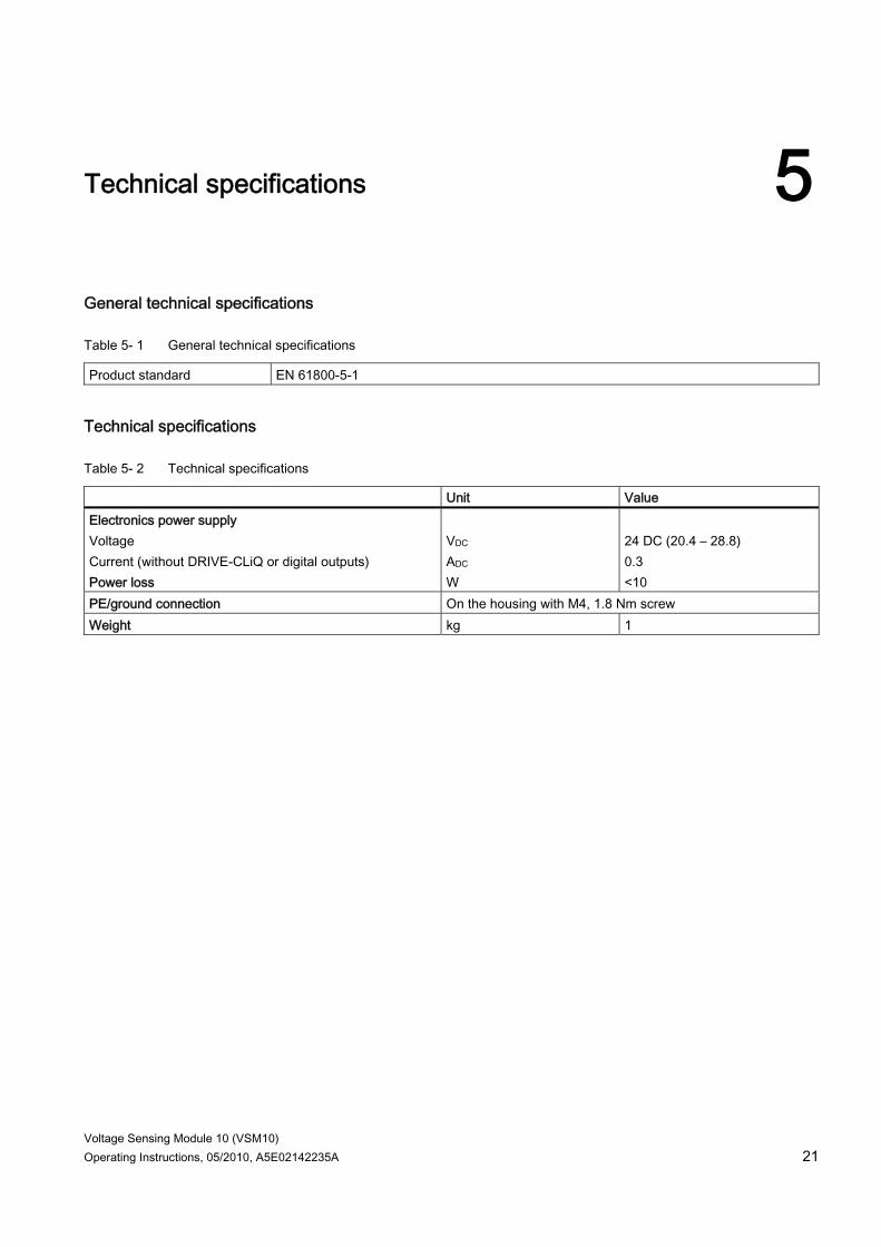
General technical specifications
Table 5- 1 General technical specifications
Product standard EN 61800-5-1
Technical specifications
Table 5- 2 Technical specifications
Unit Value Electronics power supply Voltage Current (without DRIVE-CLiQ or digital outputs) Power loss
VDC ADC W
24 DC (20.4 – 28.8) 0.3 <10
PE/ground connection On the housing with M4, 1.8 Nm screw Weight kg 1

www.siemens.com/automation
Subject to change© Siemens AG 2010
Siemens AGIndustry SectorDrive TechnologiesLarge DrivesPostfach 474390025 NUREMBERGGERMANY