voltage regulated distribution transformer - j. schneider · lengthwise and crosswise din en...
TRANSCRIPT

J. Schneider Elektrotechnik GmbH J. Schneider Elektrotechnik GmbH
J. Schneider Elektrotechnik GmbH
Helmholtzstrasse 13
D-77652 Offenburg
Germany
Phone +49 / 781 / 2 06 -0
Fax +49 / 7 81 / 2 53 18
www.j-schneider.de
Jörg
Sch
aars
chm
idt D
ipl.-
Des
igne
r · w
ww
.j-sc
haar
schm
idt.d
e · t
echn
ical
mod
ifica
tions
pos
sibl
e · 0
912
· rep
rint0
413
Voltage Regulated Distribution Transformer
SmartActiveTransformer
The economical alternativeJ. Schneider Elektrotechnik GmbH
The economical alternative to grid expansion – optimal grid capacity
utilisation: the integration of increasingly decentralised energy sources
feeding renewable energy into low-voltage systems presents energy
providers with increasingly greater challenges.
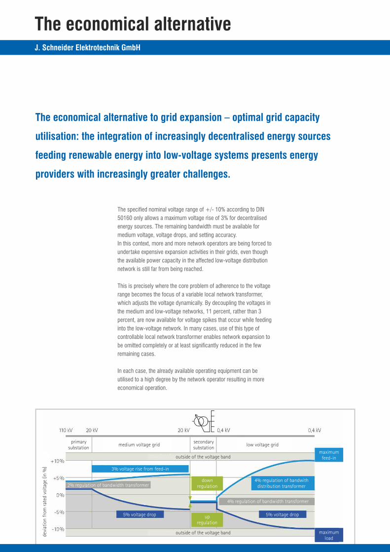
The specified nominal voltage range of +/- 10% according to DIN
50160 only allows a maximum voltage rise of 3% for decentralised
energy sources. The remaining bandwidth must be available for
medium voltage, voltage drops, and setting accuracy.
In this context, more and more network operators are being forced to
undertake expensive expansion activities in their grids, even though
the available power capacity in the affected low-voltage distribution
network is still far from being reached.
This is precisely where the core problem of adherence to the voltage
range becomes the focus of a variable local network transformer,
which adjusts the voltage dynamically. By decoupling the voltages in
the medium and low-voltage networks, 11 percent, rather than 3
percent, are now available for voltage spikes that occur while feeding
into the low-voltage network. In many cases, use of this type of
controllable local network transformer enables network expansion to
be omitted completely or at least significantly reduced in the few
remaining cases.
In each case, the already available operating equipment can be
utilised to a high degree by the network operator resulting in more
economical operation.
The ideal solution for power distribution network operators
Maintenance-free, long-lasting
· no lifetime-limited electronics in the circuit breaker
· maintenance-free for its entire lifespan thanks to vacuum technology
· lifetime analogy to conventional local network transformers
Low lifecycle costs
· 700,000 reliable circuits make maintenance unnecessary
· the on-load tap changer operates reliably throughout the
entire lifetime of the transformer
· motor and controller may be easily replaced as required
Maximum operating reliability
· critical operating conditions are excluded by the reactor principle
· a communication interface enables integration with the
control room as required
· the SmartActiveTransformer features the entire know-how of more
than 35,000 vacuum switches and over 10,000 reactor switches
developed by Maschinenfabrik Reinhausen, which are used around
the world
Fit for the future
· a maximum of 9 operating positions and step spacing of
up to 3% enable a control range up to 24%
· the on-load tap changer is also configurable asymmetrically for
situations primarily featuring loads or primarily featuring feeds
· The voltage range of +/- 10% as per DIN 50160 can be fully utilised
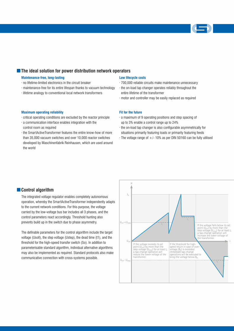
Control algorithm
The integrated voltage regulator enables completely autonomous
operation, whereby the SmartActiveTransformer independently adapts
to the current network conditions. For this purpose, the voltage
carried by the low-voltage bus bar includes all 3 phases, and the
control parameters react accordingly. Threshold hunting also
prevents build up in the switch due to phase asymmetry.
The definable parameters for the control algorithm include the target
voltage (Usoll), the step voltage (Ustep), the dead time (t1), and the
threshold for the high-speed transfer switch (So). In addition to
parameterisable standard algorithm, individual alternative algorithms
may also be implemented as required. Standard protocols also make
communicative connection with cross-systems possible.
primarysubstation
secondarysubstation
medium voltage grid low voltage grid
maximumfeed-in
maximumload
5% voltage drop5% voltage drop
11% voltage risefrom feed-in
downregulation
upregulation
outside of the voltage band
outside of the voltage band
4% regulation of bandwithdistribution transformer2% regulation of bandwidth transformer
4% regulation of bandwidth transformer
3% voltage rise from feed-in
devi
atio
n fr
om r
ated
vol
tage
(in
%)
If the voltage exceeds its set point (U ) by more than the refstep voltage (U ) for at least t, stepa tap-change operation will reduce the lower voltage of the transformer.
If the threshold for high-speed return in case of over-voltage (B ) is exceeded 0immediate tap-change operations will be executed to bring the voltage below B .0
If the voltage falls below its set point (U ) by more than the refstep voltage (U ) for at least t, stepa tap-change operation will increase the lower voltage of the transformer.
U + Uref step
U - Uref step
Uref
The economical alternativeJ. Schneider Elektrotechnik GmbH
The economical alternative to grid expansion – optimal grid capacity
utilisation: the integration of increasingly decentralised energy sources
feeding renewable energy into low-voltage systems presents energy
providers with increasingly greater challenges.
The specified nominal voltage range of +/- 10% according to DIN
50160 only allows a maximum voltage rise of 3% for decentralised
energy sources. The remaining bandwidth must be available for
medium voltage, voltage drops, and setting accuracy.
In this context, more and more network operators are being forced to
undertake expensive expansion activities in their grids, even though
the available power capacity in the affected low-voltage distribution
network is still far from being reached.
This is precisely where the core problem of adherence to the voltage
range becomes the focus of a variable local network transformer,
which adjusts the voltage dynamically. By decoupling the voltages in
the medium and low-voltage networks, 11 percent, rather than 3
percent, are now available for voltage spikes that occur while feeding
into the low-voltage network. In many cases, use of this type of
controllable local network transformer enables network expansion to
be omitted completely or at least significantly reduced in the few
remaining cases.
In each case, the already available operating equipment can be
utilised to a high degree by the network operator resulting in more
economical operation.
The ideal solution for power distribution network operators
Maintenance-free, long-lasting
· no lifetime-limited electronics in the circuit breaker
· maintenance-free for its entire lifespan thanks to vacuum technology
· lifetime analogy to conventional local network transformers
Low lifecycle costs
· 700,000 reliable circuits make maintenance unnecessary
· the on-load tap changer operates reliably throughout the
entire lifetime of the transformer
· motor and controller may be easily replaced as required
Maximum operating reliability
· critical operating conditions are excluded by the reactor principle
· a communication interface enables integration with the
control room as required
· the SmartActiveTransformer features the entire know-how of more
than 35,000 vacuum switches and over 10,000 reactor switches
developed by Maschinenfabrik Reinhausen, which are used around
the world
Fit for the future
· a maximum of 9 operating positions and step spacing of
up to 3% enable a control range up to 24%
· the on-load tap changer is also configurable asymmetrically for
situations primarily featuring loads or primarily featuring feeds
· The voltage range of +/- 10% as per DIN 50160 can be fully utilised
Control algorithm
The integrated voltage regulator enables completely autonomous
operation, whereby the SmartActiveTransformer independently adapts
to the current network conditions. For this purpose, the voltage
carried by the low-voltage bus bar includes all 3 phases, and the
control parameters react accordingly. Threshold hunting also
prevents build up in the switch due to phase asymmetry.
The definable parameters for the control algorithm include the target
voltage (Usoll), the step voltage (Ustep), the dead time (t1), and the
threshold for the high-speed transfer switch (So). In addition to
parameterisable standard algorithm, individual alternative algorithms
may also be implemented as required. Standard protocols also make
communicative connection with cross-systems possible.
primarysubstation
secondarysubstation
medium voltage grid low voltage grid
maximumfeed-in
maximumload
5% voltage drop5% voltage drop
11% voltage risefrom feed-in
downregulation
upregulation
outside of the voltage band
outside of the voltage band
4% regulation of bandwithdistribution transformer2% regulation of bandwidth transformer
4% regulation of bandwidth transformer
3% voltage rise from feed-in
devi
atio
n fr
om r
ated
vol
tage
(in
%)
If the voltage exceeds its set point (U ) by more than the refstep voltage (U ) for at least t, stepa tap-change operation will reduce the lower voltage of the transformer.
If the threshold for high-speed return in case of over-voltage (B ) is exceeded 0immediate tap-change operations will be executed to bring the voltage below B .0
If the voltage falls below its set point (U ) by more than the refstep voltage (U ) for at least t, stepa tap-change operation will increase the lower voltage of the transformer.
U + Uref step
U - Uref step
Uref
J. Schneider Elektrotechnik GmbH
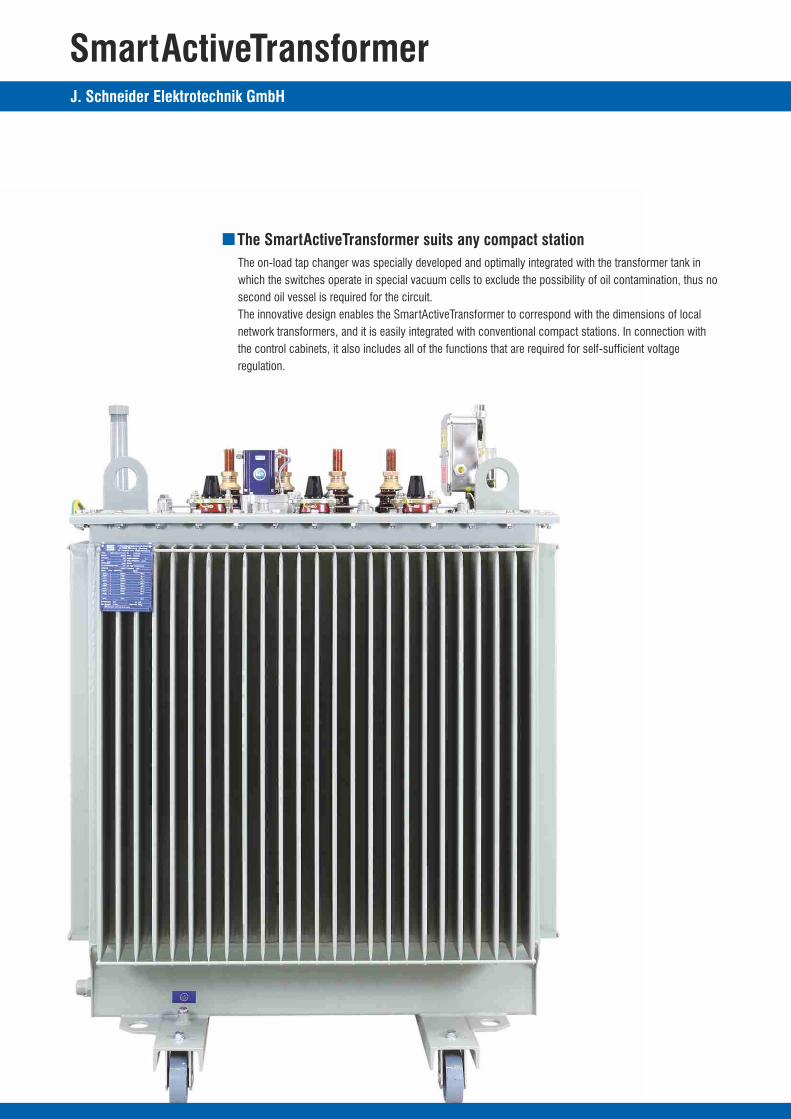
SmartActiveTransformer
The SmartActiveTransformer suits any compact station
The on-load tap changer was specially developed and optimally integrated with the transformer tank in
which the switches operate in special vacuum cells to exclude the possibility of oil contamination, thus no
second oil vessel is required for the circuit.
The innovative design enables the SmartActiveTransformer to correspond with the dimensions of local
network transformers, and it is easily integrated with conventional compact stations. In connection with
the control cabinets, it also includes all of the functions that are required for self-sufficient voltage
regulation.
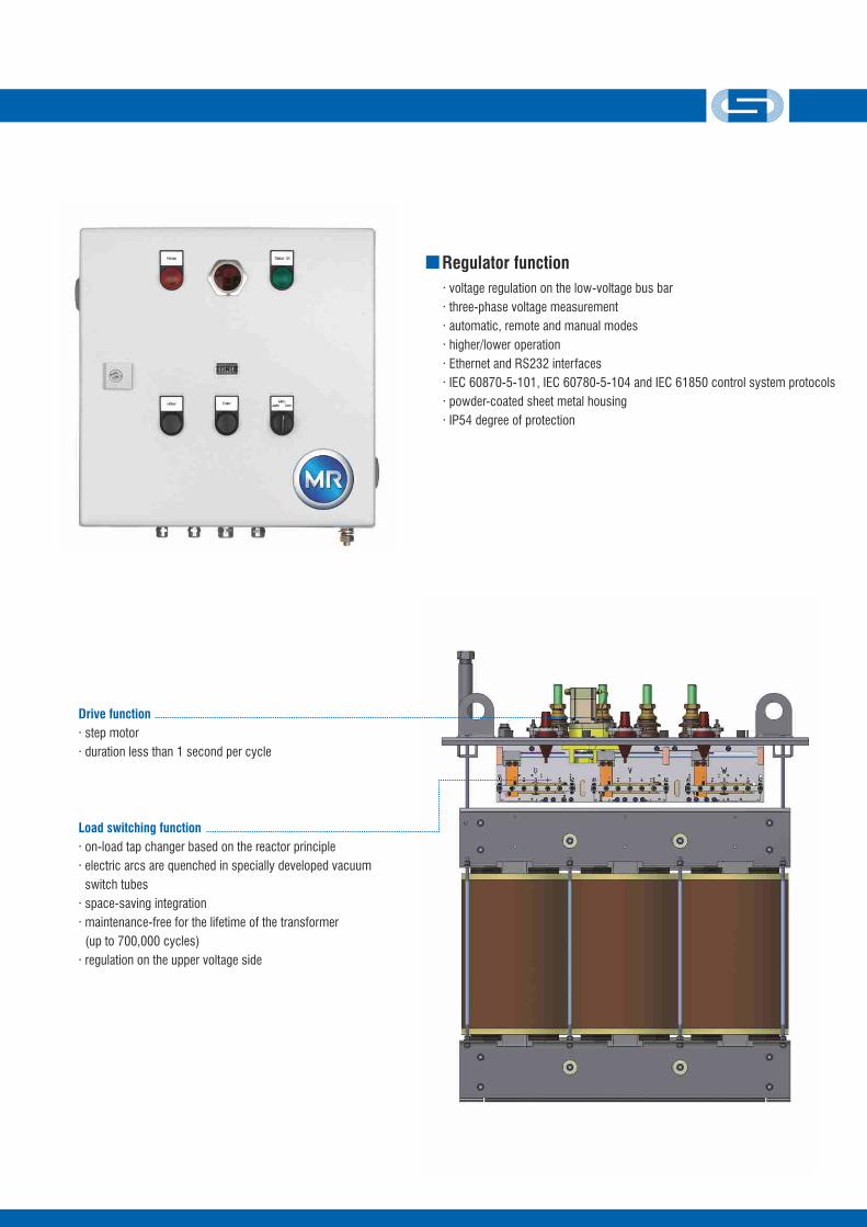
Drive function
· step motor
· duration less than 1 second per cycle
Load switching function
· on-load tap changer based on the reactor principle
· electric arcs are quenched in specially developed vacuum
switch tubes
· space-saving integration
· maintenance-free for the lifetime of the transformer
(up to 700,000 cycles)
· regulation on the upper voltage side
Regulator function
· voltage regulation on the low-voltage bus bar
· three-phase voltage measurement
· automatic, remote and manual modes
· higher/lower operation
· Ethernet and RS232 interfaces
· IEC 60870-5-101, IEC 60780-5-104 and IEC 61850 control system protocols
· powder-coated sheet metal housing
· IP54 degree of protection
J. Schneider Elektrotechnik GmbH
SmartActiveTransformer
The SmartActiveTransformer suits any compact station
The on-load tap changer was specially developed and optimally integrated with the transformer tank in
which the switches operate in special vacuum cells to exclude the possibility of oil contamination, thus no
second oil vessel is required for the circuit.
The innovative design enables the SmartActiveTransformer to correspond with the dimensions of local
network transformers, and it is easily integrated with conventional compact stations. In connection with
the control cabinets, it also includes all of the functions that are required for self-sufficient voltage
regulation.
Drive function
· step motor
· duration less than 1 second per cycle
Load switching function
· on-load tap changer based on the reactor principle
· electric arcs are quenched in specially developed vacuum
switch tubes
· space-saving integration
· maintenance-free for the lifetime of the transformer
(up to 700,000 cycles)
· regulation on the upper voltage side
Regulator function
· voltage regulation on the low-voltage bus bar
· three-phase voltage measurement
· automatic, remote and manual modes
· higher/lower operation
· Ethernet and RS232 interfaces
· IEC 60870-5-101, IEC 60780-5-104 and IEC 61850 control system protocols
· powder-coated sheet metal housing
· IP54 degree of protection

J. Schneider Elektrotechnik GmbH
Technical data
copper / alu at B – C0 K
selectable, max. 24 kV voltage class
up to max 9 steps, configuration selectable
e.g. +/- 4 x „X%“; +4/-3 x „X%“; +6/-2 x „X%“
selectable, max. 600V, common 1,5%, 2%, 2,5%
50 Hz
selectable
Dyn 5
ONAN
1000 m over NN
12 - 24 kV / 250 A plug-bushing DIN 50190
flange connection DIN 43675
hermetic-corrugated tank
non
thermometer pocket according to DIN 42554 on LV side
lengthwise and crosswise DIN EN 50216-4, material: steel
RAL 7033, total coating thickness >= 140 µm
more on request
12 - 24 kV / 250 A ceramic-bushing
DIN 50386
conductor terminal IEC 61238
transformer protection DGPT 2
dial thermometer
more on request
winding material
high voltage
steps
step voltages
frequency
low voltage
vector group
cooling
max. installation altitude
HV bushings
LV-bushings
tank type
protective device
thermometer pocket
driving rolls
coating
OptionsTechnical data SmartActiveTransformer
300
430
600
560
650
415
590
780
740
900
2750
3850
5400
5600
7000
1910
2380
2950
3150
3500
360
520
730
680
800
480
680
910
860
1050
2750
3850
5400
5600
7000
1740
2200
2600
2750
2950
360
520
730
680
800
480
680
910
860
1050
3250
4600
6500
6750
8400
1650
2000
2400
2550
2750
250
400
630
630
800
4
4
4
6
6
Power loss
SN P0 (Trafo) P0 (Trafo) P0 (Trafo)P0 (Trafo+PA) P0 (Trafo+PA) P0 (Trafo+PA)P0 (Trafo+PA) P0 (Trafo+PA) P0 (Trafo+PA)PK (Trafo+PA) PK (Trafo+PA) P0 (Trafo+PA)weight weight weight
A0 B0 B0 <=B +15%0 <=C +15%0 <=C +15%0BK BK CK
uk
[kVA] [W] [W] [W][W] [W] [W][W] [W] [W][W] [W] [W][kg] [kg] [kg][%]1U 1V 1W
2N 2U 2V 2W
G G
F F F
B
EJ
A
D H
C
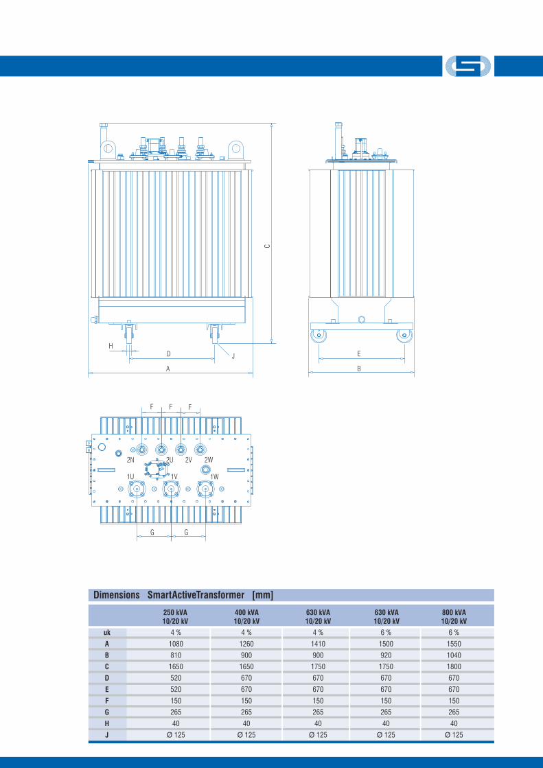
4 %
1080
810
1650
520
520
150
265
40
Ø 125
4 %
1260
900
1650
670
670
150
265
40
Ø 125
4 %
1410
900
1750
670
670
150
265
40
Ø 125
6 %
1500
920
1750
670
670
150
265
40
Ø 125
6 %
1550
1040
1800
670
670
150
265
40
Ø 125
uk
A
B
C
D
E
F
G
H
J
Dimensions SmartActiveTransformer [mm]
250 kVA10/20 kV
400 kVA10/20 kV
630 kVA10/20 kV
630 kVA10/20 kV
800 kVA10/20 kV
3 x 400 V
1,0 A
50 Hz
2 kV / 1 minute
0,9 s
3 s
Ethernet, RS 232
IEC 60870-5-101, IEC 60870-5-104, IEC 61850
380 x 380 x 180 mm
15 kg
voltage
current
frequency
test voltage to ground
duration of tap change operation
shortest gap between tap-change operation
interfaces
protocols
housing (W x H x D)
weight
Technical data voltage regulator and control cabinet
A – B0 K B – B0 K B – C0 K
J. Schneider Elektrotechnik GmbH
Technical data
copper / alu at B – C0 K
selectable, max. 24 kV voltage class
up to max 9 steps, configuration selectable
e.g. +/- 4 x „X%“; +4/-3 x „X%“; +6/-2 x „X%“
selectable, max. 600V, common 1,5%, 2%, 2,5%
50 Hz
selectable
Dyn 5
ONAN
1000 m over NN
12 - 24 kV / 250 A plug-bushing DIN 50190
flange connection DIN 43675
hermetic-corrugated tank
non
thermometer pocket according to DIN 42554 on LV side
lengthwise and crosswise DIN EN 50216-4, material: steel
RAL 7033, total coating thickness >= 140 µm
more on request
12 - 24 kV / 250 A ceramic-bushing
DIN 50386
conductor terminal IEC 61238
transformer protection DGPT 2
dial thermometer
more on request
winding material
high voltage
steps
step voltages
frequency
low voltage
vector group
cooling
max. installation altitude
HV bushings
LV-bushings
tank type
protective device
thermometer pocket
driving rolls
coating
OptionsTechnical data SmartActiveTransformer
300
430
600
560
650
415
590
780
740
900
2750
3850
5400
5600
7000
1910
2380
2950
3150
3500
360
520
730
680
800
480
680
910
860
1050
2750
3850
5400
5600
7000
1740
2200
2600
2750
2950
360
520
730
680
800
480
680
910
860
1050
3250
4600
6500
6750
8400
1650
2000
2400
2550
2750
250
400
630
630
800
4
4
4
6
6
Power loss
SN P0 (Trafo) P0 (Trafo) P0 (Trafo)P0 (Trafo+PA) P0 (Trafo+PA) P0 (Trafo+PA)P0 (Trafo+PA) P0 (Trafo+PA) P0 (Trafo+PA)PK (Trafo+PA) PK (Trafo+PA) P0 (Trafo+PA)weight weight weight
A0 B0 B0 <=B +15%0 <=C +15%0 <=C +15%0BK BK CK
uk
[kVA] [W] [W] [W][W] [W] [W][W] [W] [W][W] [W] [W][kg] [kg] [kg][%]1U 1V 1W
2N 2U 2V 2W
G G
F F F
B
EJ
A
D H
C
4 %
1080
810
1650
520
520
150
265
40
Ø 125
4 %
1260
900
1650
670
670
150
265
40
Ø 125
4 %
1410
900
1750
670
670
150
265
40
Ø 125
6 %
1500
920
1750
670
670
150
265
40
Ø 125
6 %
1550
1040
1800
670
670
150
265
40
Ø 125
uk
A
B
C
D
E
F
G
H
J
Dimensions SmartActiveTransformer [mm]
250 kVA10/20 kV
400 kVA10/20 kV
630 kVA10/20 kV
630 kVA10/20 kV
800 kVA10/20 kV
3 x 400 V
1,0 A
50 Hz
2 kV / 1 minute
0,9 s
3 s
Ethernet, RS 232
IEC 60870-5-101, IEC 60870-5-104, IEC 61850
380 x 380 x 180 mm
15 kg
voltage
current
frequency
test voltage to ground
duration of tap change operation
shortest gap between tap-change operation
interfaces
protocols
housing (W x H x D)
weight
Technical data voltage regulator and control cabinet
A – B0 K B – B0 K B – C0 K
J. Schneider Elektrotechnik GmbH J. Schneider Elektrotechnik GmbH
J. Schneider Elektrotechnik GmbH
Helmholtzstrasse 13
D-77652 Offenburg
Germany
Phone +49 / 781 / 2 06 -0
Fax +49 / 7 81 / 2 53 18
www.j-schneider.de
Jörg
Sch
aars
chm
idt D
ipl.-
Des
igne
r · w
ww
.j-sc
haar
schm
idt.d
e · t
echn
ical
mod
ifica
tions
pos
sibl
e · 0
912
· rep
rint0
413
Voltage Regulated Distribution Transformer
SmartActiveTransformer