vol. 5, issue 7, july 2016 optimum rotor flux control for ... rotor flux control for indirect vector...
TRANSCRIPT

ISSN(Online) : 2319-8753
ISSN (Print) : 2347-6710
International Journal of Innovative Research in Science, Engineering and Technology
(An ISO 3297: 2007 Certified Organization)
Vol. 5, Issue 7, July 2016
Copyright to IJIRSET DOI:10.15680/IJIRSET.2016.0507032 12264
Optimum Rotor Flux Control for Indirect Vector Control of Induction Motor using Loss
Optimization
Juber Shaikh 1, Assistant Professor, Department of Electrical Engineering, Nagesh Karajagi Orchid college of Engineering &
Technology, Maharashtra , India1
ABSTRACT: Induction motor is widely used in industrial applications but at light load condition, without any control such motor consumes more power ,which affects the operational or running cost. This paper present simulation using MATLAB SIMULINK. & its hardware is implemented by using DSP TMS320F28069 for optimization of rotor flux of the indirect vector control of induction motor. For maximum efficiency, the optimization of flux based on load is done, and the result is analyzed. KEYWORDS: Optimum flux, Vector control, Loss model.
I. INTRODUCTION
Induction motors are mostly used in industrial application due to their high performance, robustness, efficiency and cost. More than 40% of the total electric energy generated is consumed by electric motors. Recently, the concern about the enormous use of electrical energy and its adverse impact on the environment is growing. Generally induction motor is designed to have maximum efficiency near full load.At light load condition, the copper loss is less compared to iron loss and the efficiency is poor [1]. So an attempt is madeto increase the efficiency of an induction motor even at light loads by the flux optimization method. An indirect vector control method has a good dynamic performance due to the inherent decoupling between d-axis (flux producing component) and q-axis (torque producing component) components of current, similar to a separately excited DC machine. Efficiency of the motor can be increased by means of loss reduction which can be done by the following methods; 1) Appropriate motor selection and design; 2) Improved waveform supplied by the inverter; 3) Using suitable control method. Generally, motor is designed to have maximum efficiency at rated conditions [2]. Mostly motor operates at other than rated conditions. Under these conditions, it is not possible to improve the machine efficiency by machine design or by waveform shaping technique; hence it is necessary to go for the suitable control algorithm [2]. The control method or the control strategy to improve the efficiency can be divided into two categories 1) Search controller 2) Loss model based controller [3]. The basic principle of search controller is to measure the input power and then iteratively search the flux until the minimum power is detected for given torque and speed [4].For this vector drive, the flux is reducing in small steps to reach the optimum condition, and the problem is an increase in the time of convergence and the torque pulsation during the search process.In fuzzy logic based search controller method, we speed up the convergence time, but we want to use compensator for torque pulsation problem [5]. In the Golden section based search algorithm, we can improve the convergence time, but the problem is selecting the upper and lower limit of flux producing current before the algorithm start.To get acceptable dynamic performance and to increase the speed of search, prior knowledge of drive system is required [6]. The advantage of loss model based approach is that it is faster than the other method. Optimum flux is decided by the machine model and extra filter and sensor not required to get the power input. Torque ripple is less compared to the other method [6].
ISSN(Online) : 2319-8753
ISSN (Print) : 2347-6710
International Journal of Innovative Research in Science, Engineering and Technology
(An ISO 3297: 2007 Certified Organization)
Vol. 5, Issue 7, July 2016
Copyright to IJIRSET DOI:10.15680/IJIRSET.2016.0507032 12265
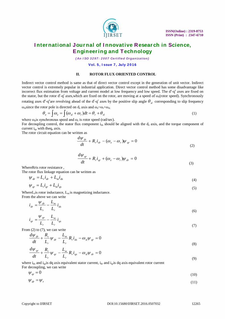
II. ROTOR FLUX ORIENTED CONTROL
Indirect vector control method is same as that of direct vector control except in the generation of unit vector. Indirect vector control is extremely popular in industrial application. Direct vector control method has some disadvantage like incorrect flux estimation from voltage and current model at low frequency and low speed. The ds-qs axes are fixed on the stator, but the rotor dr-qr axes,which are fixed on the rotor, are moving at a speed of ωr(rotor speed). Synchronously rotating axes de-qeare revolving ahead of the dr-qr axes by the positive slip angle sl corresponding to slip frequency ωslsince the rotor pole is directed on de axis and ωe=ωr+ωsl.
slrrslee dt )( (1)
where ωeis synchronous speed and ωr is rotor speed (rad/sec). For decoupling control, the stator flux component ids should be aligned with the de axis, and the torque component of current iqs with theqe axis. The rotor circuit equation can be written as
0)( qrredrrdr iR
dtd
(2)
0)( drreqrrqr iR
dtd
(3) WhereRris rotor resistance , The rotor flux linkage equation can be written as
dsmdrrdr iLiL (4)
qsmqrrqr iLiL (5)
WhereLris rotor inductance, Lm is magnetizing inductance.
From the above we can write
dsr
m
r
drdr i
LL
Li
(6)
qsr
m
r
qrqr i
LL
Li
(7)
From (2) to (7), we can write
0 qrsldsrr
mdr
r
rdr iRLL
LR
dtd
(8)
0 drslqsrr
mqr
r
rqr iRLL
LR
dtd
(9) where ids and iqsis dq axis equivalent stator current, idr and iqris dq axis equivalent rotor current For decoupling, we can write
0qr (10)
rdr (11)
ISSN(Online) : 2319-8753
ISSN (Print) : 2347-6710
International Journal of Innovative Research in Science, Engineering and Technology
(An ISO 3297: 2007 Certified Organization)
Vol. 5, Issue 7, July 2016
Copyright to IJIRSET DOI:10.15680/IJIRSET.2016.0507032 12266
0dt
d qr
(12)
So that rotor flux r is directed on de axis. Substitute(10) ,(11),and (12) in (8) and (9), then we get,
)1( siL
r
dsmr
(13)
Electromagnetic torque can be calculated by
)(22
3qsdr
r
me i
LLpT
(14)
The calculation of iq* and id* as reference current torque and flux component respectively is as following
)(22
3 **qs
r
me i
LLpT
dr
(15)
m
rd L
i * (16)
r
e
m
rq
TLL
pi
** 2
32
(17)
From the above equations, we can implement the indirect vector control of induction motor
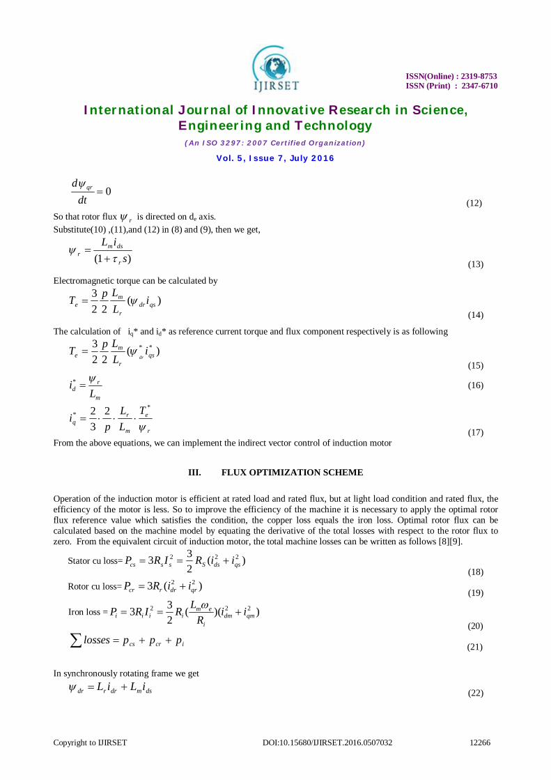
III. FLUX OPTIMIZATION SCHEME Operation of the induction motor is efficient at rated load and rated flux, but at light load condition and rated flux, the efficiency of the motor is less. So to improve the efficiency of the machine it is necessary to apply the optimal rotor flux reference value which satisfies the condition, the copper loss equals the iron loss. Optimal rotor flux can be calculated based on the machine model by equating the derivative of the total losses with respect to the rotor flux to zero. From the equivalent circuit of induction motor, the total machine losses can be written as follows [8][9].
Stator cu loss= )(233 222
qsdsSsscs iiRIRP (18)
Rotor cu loss= )(3 22qrdrrcr iiRP
(19)
Iron loss = ))((233 222
qmdmi
emiiii ii
RLRIRP
(20)
icrcs ppplosses (21)
In synchronously rotating frame we get
dsmdrrdr iLiL (22)

ISSN(Online) : 2319-8753
ISSN (Print) : 2347-6710
International Journal of Innovative Research in Science, Engineering and Technology
(An ISO 3297: 2007 Certified Organization)
Vol. 5, Issue 7, July 2016
Copyright to IJIRSET DOI:10.15680/IJIRSET.2016.0507032 12267
qsmqrrqr iLiL (23)
The perfect decoupling is achieved by 0qr
(24)
rdr (25) Then from rotor field oriented indirect vector control of induction motor we can write
0dri (26)
qsr
mqr i
LLi
(27)
Put value of iqr,idr in the losses equation, then we get
))((23)(3)(
23 222222
qmdmi
emiqsdsrcrqsdsS ii
RLRiiRPiiRlosses
(28)
WhereRs is stator resistance, Riis iron loss resistance. The stator dq current components are
qmlr
rr
i
eqs i
LL
Ri
(29)
qmi
emr
mds i
RL
Li
1
(30)
Substitute (29) and (30) in (28), then
][)(23)(
23)()[(
23 2
2
222222
qmm
r
i
emiqm
lr
mrqm
lr
rr
i
eqm
i
em
m
rS i
LRLRi
LLRi
LL
Ri
RL
LRLosses
(31)
WhereLlris rotor leakage inductance.
From (26) and (27) we can write,
qmrlr
mqrrqsr
r
mem i
LLpipi
LLpT (32)
where p is number of pair poles. After simplification,we get,
22
2 ))(()()()(r
emeemere
TcTbalosses
(33)
where
])([23)( 2
2
2i
eis
m
ss R
RRLRa
,
To get the optimum flux, partial derivative of (33) with respect to rotor flux

ISSN(Online) : 2319-8753
ISSN (Print) : 2347-6710
International Journal of Innovative Research in Science, Engineering and Technology
(An ISO 3297: 2007 Certified Organization)
Vol. 5, Issue 7, July 2016
Copyright to IJIRSET DOI:10.15680/IJIRSET.2016.0507032 12268
01)(2)(20)(
32
r
emerer
TcaLosses
Then
emr T (34)
Where
4ac
The flux value is a function of the electromagnetic torque and the coefficient, which depends on the machine parameters. So the optimum flux can be estimated as a function of torque and speed of the machine.
IV. SCHEMATIC BLOCK DIAGRAM OF THE SYSTEM The complete induction motor vector control system is basically designed according to the MATLAB simulation. Due to practical limitations some modifications are made during the implementation stage. Hardware is implemented for 0.373kW motor instead of 4 kW motor which is simulated in MATLAB. Only two phase currents isa and isb are measured instead of all three phase currents. For balanced condition, three phases are balanced and hence one phase current can be calculated from the other two phase currents. Same is applicable to the voltage. Fig.1 shows the complete block diagram of the hardware implementation.
Fig.1: Block diagram of implemented control algorithm

ISSN(Online) : 2319-8753
ISSN (Print) : 2347-6710
International Journal of Innovative Research in Science, Engineering and Technology
(An ISO 3297: 2007 Certified Organization)
Vol. 5, Issue 7, July 2016
Copyright to IJIRSET DOI:10.15680/IJIRSET.2016.0507032 12269
V. LABORATORY SETUP OF THE COMPLETE SYSTEM
The laboratory setup with a step up transformer and filter is as shown in Fig.2. Setup consists of 0.37kW inductions motor which is fed by Voltage Source Inverter (VSI). The two current sensors-LEM HX-03 and two potential transformers are used to sense the currents and voltages respectively. Potential transformers are used to sense the currents and voltages respectively.
Fig.2: Laboratory setup
a) SIMULATION RESULTS
In Fig.3& fig.4 shows Actual speed & torque are follows the reference speed & torque under load condition ( at 5 Nm). In simulation at time zero to 2.5 sec the system is without flux optimisation & after 2.5 sec system is with flux optimization

ISSN(Online) : 2319-8753
ISSN (Print) : 2347-6710
International Journal of Innovative Research in Science, Engineering and Technology
(An ISO 3297: 2007 Certified Organization)
Vol. 5, Issue 7, July 2016
Copyright to IJIRSET DOI:10.15680/IJIRSET.2016.0507032 12270
Fig.3: Actual and reference speed (1430 rpm) Fig.4: Actual and reference torque (5Nm)
Fig 5 shows the power consumption of motor under load condition (at 5 Nm) at zero to2.5 sec the system is without flux optimization & after 2.5 sec the system is with optimization .In flux optimization region Power consumption is Less as compared to without optimization ..Fig 6 shows reduction of flux from its rated value to optimum value in flux optimization region which is applied to the system after 2.5 sec
Fig.5: Reduction in power after flux optimization Fig 6: Reduction in the rotor flux after flux at 2.5sec for torque 5Nm optimization at 2.5 sec for torque 5 Nm
b) HARDWARE RESULTS Initially the current sensor circuit is tested by measuring the current of three phase induction motor at no load condition which is supplied by 230 volt mains supply directly. Current sensors output is shown in the following diagrams.
Rated Flux
Optimum Flux
With optimization
Without Optimization
ISSN(Online) : 2319-8753
ISSN (Print) : 2347-6710
International Journal of Innovative Research in Science, Engineering and Technology
(An ISO 3297: 2007 Certified Organization)
Vol. 5, Issue 7, July 2016
Copyright to IJIRSET DOI:10.15680/IJIRSET.2016.0507032 12271
(a) (b)
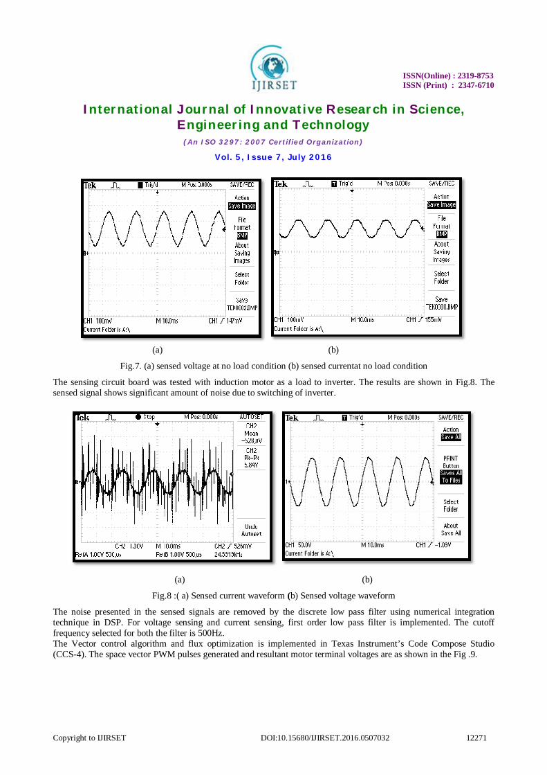
Fig.7. (a) sensed voltage at no load condition (b) sensed currentat no load condition
The sensing circuit board was tested with induction motor as a load to inverter. The results are shown in Fig.8. The sensed signal shows significant amount of noise due to switching of inverter.
(a) (b)
Fig.8 :( a) Sensed current waveform (b) Sensed voltage waveform
The noise presented in the sensed signals are removed by the discrete low pass filter using numerical integration technique in DSP. For voltage sensing and current sensing, first order low pass filter is implemented. The cutoff frequency selected for both the filter is 500Hz. The Vector control algorithm and flux optimization is implemented in Texas Instrument’s Code Compose Studio (CCS-4). The space vector PWM pulses generated and resultant motor terminal voltages are as shown in the Fig .9.

ISSN(Online) : 2319-8753
ISSN (Print) : 2347-6710
International Journal of Innovative Research in Science, Engineering and Technology
(An ISO 3297: 2007 Certified Organization)
Vol. 5, Issue 7, July 2016
Copyright to IJIRSET DOI:10.15680/IJIRSET.2016.0507032 12272
( a) b)
Fig.9: (a) Space Vector Modulated PWM gate pulses (b) Motor’s single phase output terminal voltages after filtering.
( a) b)
Fig.10.(a) CCS-4 Screen shot indicating sector selection of space vector modulation(b) CCS-4 Screen shot indicating torque and flux estimation based on measurement of actual motor terminal
Fig.10 (a) shows the screen shot of CCS-4 indicating the SVM implementation, where the reference voltage vector position is identified in terms of sector which repetitively moves from 1 to 6 and repeat.Fig 10(b) shows the screenshot of CCS-4 for Torque and flux estimation based on actual measurement of sensed signals. For successful implementation of Vector control of induction motor is critical to estimate the actual stator flux and motor torque accurately. Because of the noise present in the signal, it is difficult to estimate torque and flux.
VI.CONCLUSION DC drives are simpler in control because they independently control flux and torque which is not the case with induction motor drive. To enable the independent control of flux and torque as DC machine, the stator current is resolved into two components; one is flux producing current component and the other is torque producing current component. This is referred as vector control. Indirect vector control is most effective method, which is used in industry for controlling of induction motor. Indirect vector control has a good dynamics performance. In this project work, the rotor field oriented vector control along with flux optimization is implemented. With flux optimization, we save energy. At no load or at low load condition iron loss are more compared to the copper loss, so we make both losses equal so that motor will consume less power compared to that without flux optimization. The loss model based approach utilizes the machine model to make copper loss equal to iron loss for any load condition by flux
Estimated Motor Torque
Sector -1
Sector -6
Sector -1 Estimated Motor Resultant flux

ISSN(Online) : 2319-8753
ISSN (Print) : 2347-6710
International Journal of Innovative Research in Science, Engineering and Technology
(An ISO 3297: 2007 Certified Organization)
Vol. 5, Issue 7, July 2016
Copyright to IJIRSET DOI:10.15680/IJIRSET.2016.0507032 12273
optimization. The torque ripple is less in this method. The efficiency of the machine is improved by minimizing the power loss of induction machine drives by flux optimization which is essential in energy saving point of view in the present scenario.
APPENDIX Induction motor machine parameter for Simulink:- Rated Power = 4000 W, Rated Voltage = 400 Volts, Frequency = 50 Hz, Number of poles =4, Stator Resistance = 1.405 Ω, Stator Leakage Inductance = 0.005839 Henry, Rotor Resistance referred to stator = 1.395 Ω, Rotor Inductance referred to stator = 0.005839 Henry, Mutual Inductance = 0.1722 Henry. Induction Motor parameter used for hardware: Rated Power = 373 W, Rated Voltage = 415 V, Frequency = 50 Hz, Number of poles =4, Stator Resistance = 23.405 Ω, Stator Leakage Inductance = 0.0874665 Henry, Rotor Resistance referred to stator = 38.1155 Ω, Rotor Inductance referred to stator = 0.0874665 Henry,Mutual Inductance = 0.92526 Henry.
REFERENCES [1]ChandanChakraborty and Yoichi Hori, “Fast Efficiency Optimization Technique for the Indirect Vector-Controlled Induction Motor Drives” IEEE
transactions on industry applications, vol. 39, no. 4, July/august 2003 [2]Cao-Minh Ta,Yoichi Hori, ”Convergence Improvement of Efficiency-Optimization Control of Induction Motor Drives” IEEE transactions on
industry applications, VOL. 37, NO. 6 [3] M. Nasiruddin, and Sang Woo Nam “New Online Loss-Minimization-Based Control of an Induction Motor Drive” IEEE transactions on power
electronics, Vol. 23, NO. 2 [4]Cao-Minh Ta, Yoichi Hori, “Fast Efficiency Optimization Techniques for the Indirect Vector-Controlled Induction Motor Drives” IEEE
transactions on industry Applications, vol. 37, no. 6. [5]ZengcaiQu, MikaelaRanta, Marko Hinkkanenand JormaLuomi“Loss-Minimizing Flux Level Control of Induction Motor Drives” IEEE transactions
on industry applications, vol. 48, no. 3 [6] Gilberto C.D.souso, B.K.Bose “Fuzzy logic based online efficiency optimization control of an indirect vector controlled of induction motor drive”
IEEE transactions on industrial electronics vol.42 [7]Cao-Minh Ta, Yoichi Hori “Improvement of Efficiency-Optimization Control of Induction Motor Drives” IEEE transactions on industry
applications, vol. 37, no. 6, [8]S. Grouni1, R. Ibtiouen2, M. Kidouche1, O. Touhami “Novel Loss Optimization in Induction Machines with Optimum Rotor Flux
Control”International Journal of Systems Control Vol.1-2010/Iss.4 pp. 163-169 [9] Mehdi Dhaoui, LassaadSbita, “ A New Method for Losses Minimization in IFOC Induction Motor Drives” International Journal of Systems
Control (Vol.1-2010/Iss.2)pp. 93-99. [10] Juber shaikh, Bindu R, “Flux Optimization for Indirect Vector Control of Induction Motor” 2nd nternational Conference on Global Technology
Initiatives VOL.2-2013/issue-2 pp. C-32 To 38 ISBN No.978-93-5067-450-5