vol. 3, issue 9, september 2014 use of statcom for ... · pdf fileperformance of wind farms...
TRANSCRIPT

ISSN (Print) : 2320 – 3765
ISSN (Online): 2278 – 8875
International Journal of Advanced Research in Electrical,
Electronics and Instrumentation Engineering
(An ISO 3297: 2007 Certified Organization)
Vol. 3, Issue 9, September 2014
10.15662/ijareeie.2014.0309007
Copyright to IJAREEIE www.ijareeie.com 11738
Use of STATCOM for Improving Dynamic
Performance of Wind Farms Connected in
Power Grid
K. B. Mohd. Umar Ansari1
PG Student [EPES], Dept. of EEE, AKG Engineering College, Ghaziabad, Uttar Pradesh, India1
ABSTRACT: When integrated to the power system, large wind farms pose stability and control issues. A thorough
study is needed to identify the potential problems and to develop measures to mitigate them. Although integration of
high levels of wind power into an existing transmission system does not require a major redesign, it necessitates
additional control and compensating equipment to enable recovery from severe system disturbances. This paper
investigates the use of a Static Synchronous Compensator (STATCOM) along with wind farms for the purpose of
stabilizing the grid voltage after grid-side disturbances such as a three phase short circuit fault, temporary trip of a wind
turbine and sudden load changes. The strategy focuses on a fundamental grid operational requirement to maintain
proper voltages at the point of common coupling by regulating voltage. The DC voltage at individual wind turbine
(WT) inverters is also stabilized to facilitate continuous operation of wind turbines during disturbances.
KEYWORDS: STATCOM, Bus bar, Wind turbines, Wind Generation, Transient Stability.
I.INTRODUCTION
Now a day’s wind as a significant proportion of non pollutant energy generation is widely used. The wind farm
capacity is being continuously increased through the installation of more and larger wind turbines. Voltage stability and
an efficient fault ride through capability are the basic requirements for higher penetration. Wind turbines have to be
able to continue uninterrupted operation under transient voltage conditions.
One of the major issues concerning a wind farm interconnection to a power grid concerns its dynamic stability on the
power system. Voltage instability problems occur in a power system that is not able to meet the reactive power demand
during faults and heavy loading conditions. A wind farm is usually spread over a wide area and has many wind
generators, which produce different amounts of power as they are exposed to different wind patterns.
Flexible AC Transmission Systems (FACTS) such as the Static Synchronous Compensator (STATCOM) and the
Unified Power Flow Controller (UPFC) are being used extensively in power systems because of their ability to provide
flexible power flow control. The main motivation for choosing STATCOM in wind farms is its ability to provide bus
bar system voltage support either by supplying and/or absorbing reactive power into the system.
In this paper, a STATCOM is added to the power network to provide dynamic voltage control for the wind farm,
dynamic power flow control for the transmission lines, relieve transmission congestion and improve power oscillation
damping. Simulation results show that the STATCOM devices significantly improve the performance of the wind farm
and the power network during transient disturbances.
II.STUDIED SYSTEM AND ITS SIMULINK MODEL
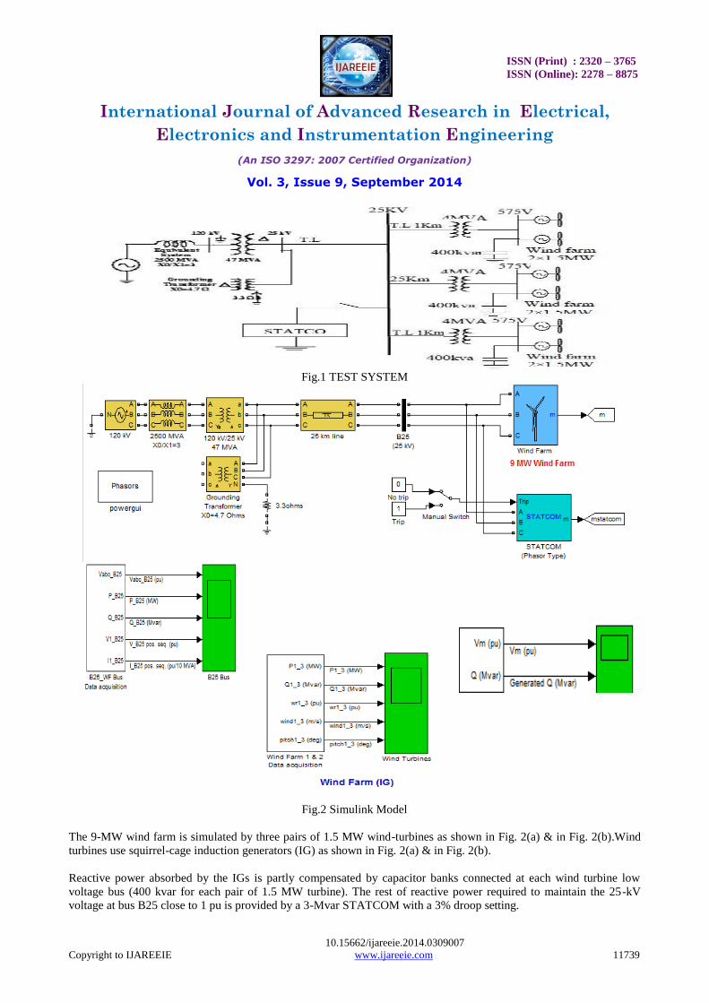
A wind farm consisting of six 1.5-MW wind turbines is connected to a 25-kV distribution system exports power to a
120-kV grid through a 25-km 25-kV feeder as shown in Fig.1. The studied power system is simulated using Simulink
Matlab software package as shown in fig 2. This paper discussed the effect of speed on wind turbines, on the studied
system which depicts the following: wind turbine rotor speed, active, reactive power, and voltage on 25kV bus with
and without STATCOM.
ISSN (Print) : 2320 – 3765
ISSN (Online): 2278 – 8875
International Journal of Advanced Research in Electrical,
Electronics and Instrumentation Engineering
(An ISO 3297: 2007 Certified Organization)
Vol. 3, Issue 9, September 2014
10.15662/ijareeie.2014.0309007
Copyright to IJAREEIE www.ijareeie.com 11739
Fig.1 TEST SYSTEM
Fig.2 Simulink Model
The 9-MW wind farm is simulated by three pairs of 1.5 MW wind-turbines as shown in Fig. 2(a) & in Fig. 2(b).Wind
turbines use squirrel-cage induction generators (IG) as shown in Fig. 2(a) & in Fig. 2(b).
Reactive power absorbed by the IGs is partly compensated by capacitor banks connected at each wind turbine low
voltage bus (400 kvar for each pair of 1.5 MW turbine). The rest of reactive power required to maintain the 25-kV
voltage at bus B25 close to 1 pu is provided by a 3-Mvar STATCOM with a 3% droop setting.
ISSN (Print) : 2320 – 3765
ISSN (Online): 2278 – 8875
International Journal of Advanced Research in Electrical,
Electronics and Instrumentation Engineering
(An ISO 3297: 2007 Certified Organization)
Vol. 3, Issue 9, September 2014
10.15662/ijareeie.2014.0309007
Copyright to IJAREEIE www.ijareeie.com 11740
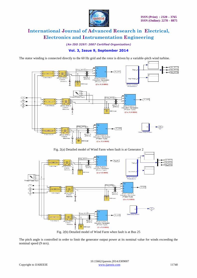
The stator winding is connected directly to the 60 Hz grid and the rotor is driven by a variable-pitch wind turbine.
Fig. 2(a) Detailed model of Wind Farm when fault is at Generator 2
Fig. 2(b) Detailed model of Wind Farm when fault is at Bus 25
The pitch angle is controlled in order to limit the generator output power at its nominal value for winds exceeding the
nominal speed (9 m/s).

ISSN (Print) : 2320 – 3765
ISSN (Online): 2278 – 8875
International Journal of Advanced Research in Electrical,
Electronics and Instrumentation Engineering
(An ISO 3297: 2007 Certified Organization)
Vol. 3, Issue 9, September 2014
10.15662/ijareeie.2014.0309007
Copyright to IJAREEIE www.ijareeie.com 11741
In order to generate power the IG speed must be slightly above the synchronous speed. Speed varies approximately
between 1 pu at no load and 1.005 pu at full load. Each wind turbine has a protection system monitoring voltage,
current and machine speed. As shown below:
A: Description of the data Acquisition circuit:
B: Data Acquisition circuit for 25kv bus:
It receive signal from the power_wing_ig/B25(25kv)/vabc. This is already defined in the toolbox.
C: Data Acquisition circuit of the STATCOM:
Under Speed
DC Overvoltage
AC Voltage Unbalance (Zero-sequence)
AC Overvoltage (positive-sequence)
AC Undervoltage (positive-sequence)
AC Current Unbalance
AC Overcurrent (positive-sequence)
Instantaneous AC Overcurrent
AC Voltage Unbalance (Negative-sequence)
Over Speed
Under Speed
DC Overvoltage
AC Voltage Unbalance (Zero-sequence)
AC Overvoltage (positive-sequence)
AC Undervoltage (positive-sequence)
AC Current Unbalance
AC Overcurrent (positive-sequence)
Instantaneous AC Overcurrent
AC Voltage Unbalance (Negative-sequence)
Over Speed
Under Speed
DC Overvoltage
AC Voltage Unbalance (Zero-sequence)
AC Overvoltage (positive-sequence)
AC Undervoltage (positive-sequence)
AC Current Unbalance
AC Overcurrent (positive-sequence)
Instantaneous AC Overcurrent
AC Voltage Unbalance (Negative-sequence)
Over Speed
2
Trip Time1_3
1
Trip1_3
0
0
0
0
0
0
0
0
0
0
TripData3
0
0
0
1
0
0
0
0
0
0
TripData2
0
0
0
0
0
0
0
0
0
0
TripData1
Vabc (pu)
Iabc (pu)
Vdc (V)
Reset
Speed (pu)
Trip
TripTime
TripStatus
Protection
System3
Vabc (pu)
Iabc (pu)
Vdc (V)
Reset
Speed (pu)
Trip
TripTime
TripStatus
Protection
System2
Vabc (pu)
Iabc (pu)
Vdc (V)
Reset
Speed (pu)
Trip
TripTime
TripStatus
Protection
System1
Vabc_B575_1
Iabc_B575_1
Vabc_B575_3
Iabc_B575_3
wr3
Vabc_B575_2
Iabc_B575_2
wr1
wr2

ISSN (Print) : 2320 – 3765
ISSN (Online): 2278 – 8875
International Journal of Advanced Research in Electrical,
Electronics and Instrumentation Engineering
(An ISO 3297: 2007 Certified Organization)
Vol. 3, Issue 9, September 2014
10.15662/ijareeie.2014.0309007
Copyright to IJAREEIE www.ijareeie.com 11742
It receive signal from the power_wing_ig/goto1 i.e from the STATCOM which is already defined in the toolbox.
D: Data Acquisition circuit of wind farm for wind turbine:
In above circuit, input is taken from output of the data main acquisition circuit of the wind farm.
III.RESPONSE OF THE SYSTEM WITH 3 MVAR STATCOM WHEN FAULT IS AT GENERATOR 2 at
(3ms – 3.1ms)
CASE 1: WITHOUT FAULT CONDITION
3.1(a) at system bus 3.1(b) at generators
Fig.3.1. Response of the system without fault and without STATCOM
When the wind speed is set at 9m/s, then it is observed from Fig. 3.1(b) the output active power for each pair of turbine
is 3MW, absorbed reactive power for each pair of turbine reaches 1.47Mvar, turbine speed for each pair of turbine
reaches to 1.005pu as shown in Fig. 3.1(b). Because of the lack of reactive power support the voltage at bus 25kV now
drops to 0.945pu as shown in Fig. 3.1(a).
ISSN (Print) : 2320 – 3765
ISSN (Online): 2278 – 8875
International Journal of Advanced Research in Electrical,
Electronics and Instrumentation Engineering
(An ISO 3297: 2007 Certified Organization)
Vol. 3, Issue 9, September 2014
10.15662/ijareeie.2014.0309007
Copyright to IJAREEIE www.ijareeie.com 11743
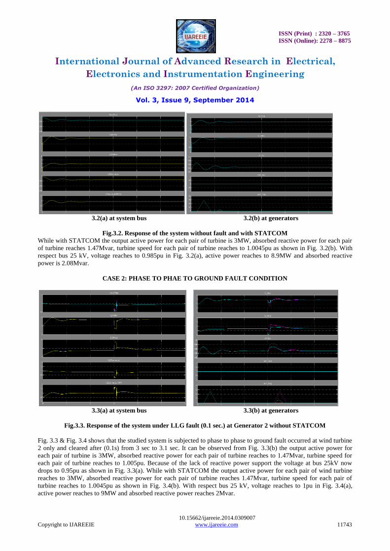
3.2(a) at system bus 3.2(b) at generators
Fig.3.2. Response of the system without fault and with STATCOM
While with STATCOM the output active power for each pair of turbine is 3MW, absorbed reactive power for each pair
of turbine reaches 1.47Mvar, turbine speed for each pair of turbine reaches to 1.0045pu as shown in Fig. 3.2(b). With
respect bus 25 kV, voltage reaches to 0.985pu in Fig. 3.2(a), active power reaches to 8.9MW and absorbed reactive
power is 2.08Mvar.
CASE 2: PHASE TO PHAE TO GROUND FAULT CONDITION
3.3(a) at system bus 3.3(b) at generators
Fig.3.3. Response of the system under LLG fault (0.1 sec.) at Generator 2 without STATCOM
Fig. 3.3 & Fig. 3.4 shows that the studied system is subjected to phase to phase to ground fault occurred at wind turbine
2 only and cleared after (0.1s) from 3 sec to 3.1 sec. It can be observed from Fig. 3.3(b) the output active power for
each pair of turbine is 3MW, absorbed reactive power for each pair of turbine reaches to 1.47Mvar, turbine speed for
each pair of turbine reaches to 1.005pu. Because of the lack of reactive power support the voltage at bus 25kV now
drops to 0.95pu as shown in Fig. 3.3(a). While with STATCOM the output active power for each pair of wind turbine
reaches to 3MW, absorbed reactive power for each pair of turbine reaches 1.47Mvar, turbine speed for each pair of
turbine reaches to 1.0045pu as shown in Fig. 3.4(b). With respect bus 25 kV, voltage reaches to 1pu in Fig. 3.4(a),
active power reaches to 9MW and absorbed reactive power reaches 2Mvar.
ISSN (Print) : 2320 – 3765
ISSN (Online): 2278 – 8875
International Journal of Advanced Research in Electrical,
Electronics and Instrumentation Engineering
(An ISO 3297: 2007 Certified Organization)
Vol. 3, Issue 9, September 2014
10.15662/ijareeie.2014.0309007
Copyright to IJAREEIE www.ijareeie.com 11744
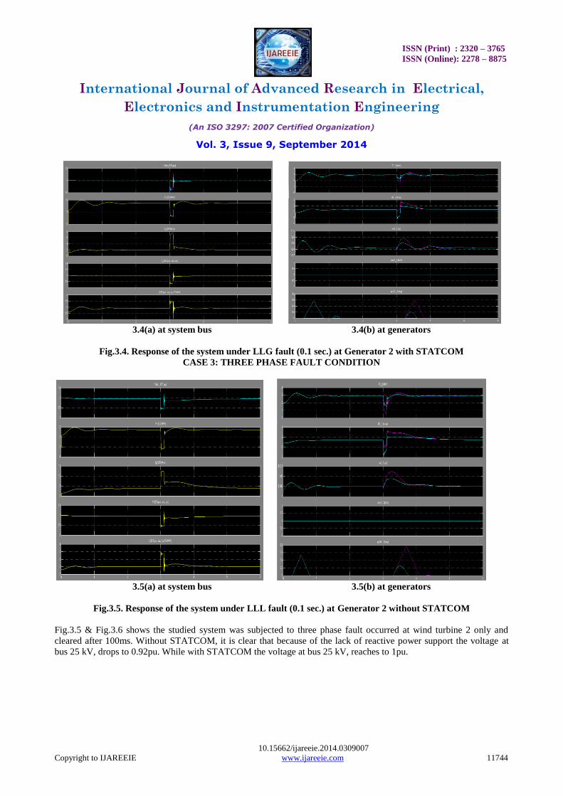
3.4(a) at system bus 3.4(b) at generators
Fig.3.4. Response of the system under LLG fault (0.1 sec.) at Generator 2 with STATCOM
CASE 3: THREE PHASE FAULT CONDITION
3.5(a) at system bus 3.5(b) at generators
Fig.3.5. Response of the system under LLL fault (0.1 sec.) at Generator 2 without STATCOM
Fig.3.5 & Fig.3.6 shows the studied system was subjected to three phase fault occurred at wind turbine 2 only and
cleared after 100ms. Without STATCOM, it is clear that because of the lack of reactive power support the voltage at
bus 25 kV, drops to 0.92pu. While with STATCOM the voltage at bus 25 kV, reaches to 1pu.
ISSN (Print) : 2320 – 3765
ISSN (Online): 2278 – 8875
International Journal of Advanced Research in Electrical,
Electronics and Instrumentation Engineering
(An ISO 3297: 2007 Certified Organization)
Vol. 3, Issue 9, September 2014
10.15662/ijareeie.2014.0309007
Copyright to IJAREEIE www.ijareeie.com 11745
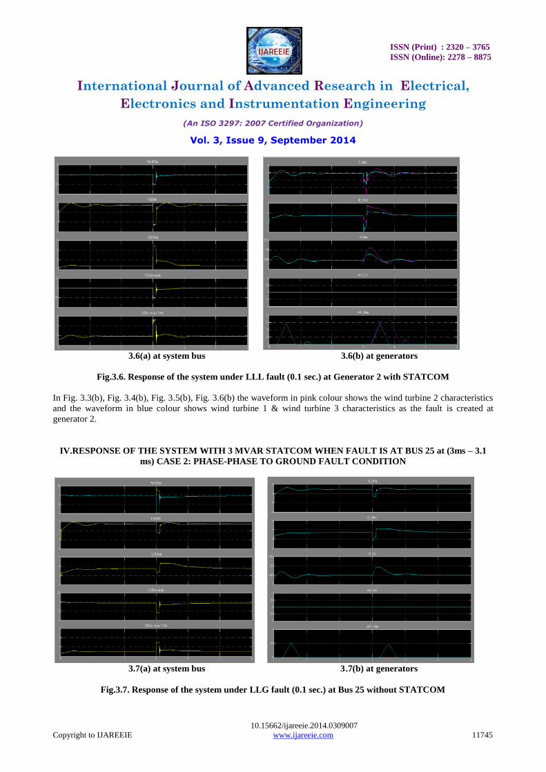
3.6(a) at system bus 3.6(b) at generators
Fig.3.6. Response of the system under LLL fault (0.1 sec.) at Generator 2 with STATCOM
In Fig. 3.3(b), Fig. 3.4(b), Fig. 3.5(b), Fig. 3.6(b) the waveform in pink colour shows the wind turbine 2 characteristics
and the waveform in blue colour shows wind turbine 1 & wind turbine 3 characteristics as the fault is created at
generator 2.
IV.RESPONSE OF THE SYSTEM WITH 3 MVAR STATCOM WHEN FAULT IS AT BUS 25 at (3ms – 3.1
ms) CASE 2: PHASE-PHASE TO GROUND FAULT CONDITION
3.7(a) at system bus 3.7(b) at generators
Fig.3.7. Response of the system under LLG fault (0.1 sec.) at Bus 25 without STATCOM
ISSN (Print) : 2320 – 3765
ISSN (Online): 2278 – 8875
International Journal of Advanced Research in Electrical,
Electronics and Instrumentation Engineering
(An ISO 3297: 2007 Certified Organization)
Vol. 3, Issue 9, September 2014
10.15662/ijareeie.2014.0309007
Copyright to IJAREEIE www.ijareeie.com 11746
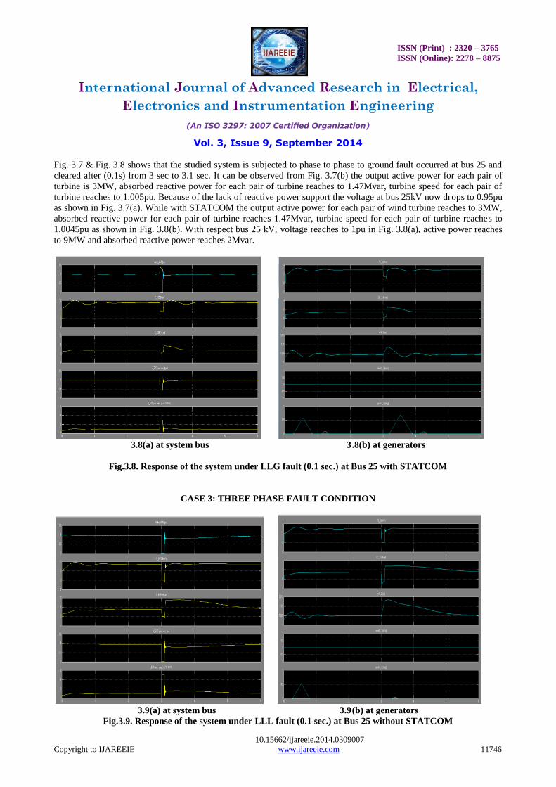
Fig. 3.7 & Fig. 3.8 shows that the studied system is subjected to phase to phase to ground fault occurred at bus 25 and
cleared after (0.1s) from 3 sec to 3.1 sec. It can be observed from Fig. 3.7(b) the output active power for each pair of
turbine is 3MW, absorbed reactive power for each pair of turbine reaches to 1.47Mvar, turbine speed for each pair of
turbine reaches to 1.005pu. Because of the lack of reactive power support the voltage at bus 25kV now drops to 0.95pu
as shown in Fig. 3.7(a). While with STATCOM the output active power for each pair of wind turbine reaches to 3MW,
absorbed reactive power for each pair of turbine reaches 1.47Mvar, turbine speed for each pair of turbine reaches to
1.0045pu as shown in Fig. 3.8(b). With respect bus 25 kV, voltage reaches to 1pu in Fig. 3.8(a), active power reaches
to 9MW and absorbed reactive power reaches 2Mvar.
3.8(a) at system bus 3.8(b) at generators
Fig.3.8. Response of the system under LLG fault (0.1 sec.) at Bus 25 with STATCOM
CASE 3: THREE PHASE FAULT CONDITION
3.9(a) at system bus 3.9(b) at generators
Fig.3.9. Response of the system under LLL fault (0.1 sec.) at Bus 25 without STATCOM
ISSN (Print) : 2320 – 3765
ISSN (Online): 2278 – 8875
International Journal of Advanced Research in Electrical,
Electronics and Instrumentation Engineering
(An ISO 3297: 2007 Certified Organization)
Vol. 3, Issue 9, September 2014
10.15662/ijareeie.2014.0309007
Copyright to IJAREEIE www.ijareeie.com 11747
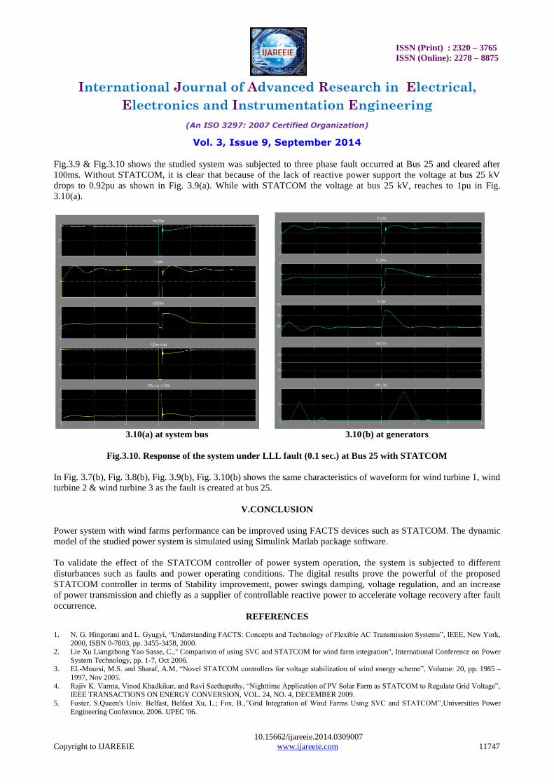
Fig.3.9 & Fig.3.10 shows the studied system was subjected to three phase fault occurred at Bus 25 and cleared after
100ms. Without STATCOM, it is clear that because of the lack of reactive power support the voltage at bus 25 kV
drops to 0.92pu as shown in Fig. 3.9(a). While with STATCOM the voltage at bus 25 kV, reaches to 1pu in Fig.
3.10(a).
3.10(a) at system bus 3.10(b) at generators
Fig.3.10. Response of the system under LLL fault (0.1 sec.) at Bus 25 with STATCOM
In Fig. 3.7(b), Fig. 3.8(b), Fig. 3.9(b), Fig. 3.10(b) shows the same characteristics of waveform for wind turbine 1, wind
turbine 2 & wind turbine 3 as the fault is created at bus 25.
V.CONCLUSION
Power system with wind farms performance can be improved using FACTS devices such as STATCOM. The dynamic
model of the studied power system is simulated using Simulink Matlab package software.
To validate the effect of the STATCOM controller of power system operation, the system is subjected to different
disturbances such as faults and power operating conditions. The digital results prove the powerful of the proposed
STATCOM controller in terms of Stability improvement, power swings damping, voltage regulation, and an increase
of power transmission and chiefly as a supplier of controllable reactive power to accelerate voltage recovery after fault
occurrence.
REFERENCES
1. N. G. Hingorani and L. Gyugyi, “Understanding FACTS: Concepts and Technology of Flexible AC Transmission Systems”, IEEE, New York,
2000, ISBN 0-7803, pp. 3455-3458, 2000. 2. Lie Xu Liangzhong Yao Sasse, C.," Comparison of using SVC and STATCOM for wind farm integration", International Conference on Power
System Technology, pp. 1-7, Oct 2006. 3. EL-Moursi, M.S. and Sharaf, A.M, “Novel STATCOM controllers for voltage stabilization of wind energy scheme”, Volume: 20, pp. 1985 –
1997, Nov 2005.
4. Rajiv K. Varma, Vinod Khadkikar, and Ravi Seethapathy, “Nighttime Application of PV Solar Farm as STATCOM to Regulate Grid Voltage”, IEEE TRANSACTIONS ON ENERGY CONVERSION, VOL. 24, NO. 4, DECEMBER 2009.
5. Foster, S.Queen's Univ. Belfast, Belfast Xu, L.; Fox, B.,”Grid Integration of Wind Farms Using SVC and STATCOM”,Universities Power
Engineering Conference, 2006. UPEC '06.

ISSN (Print) : 2320 – 3765
ISSN (Online): 2278 – 8875
International Journal of Advanced Research in Electrical,
Electronics and Instrumentation Engineering
(An ISO 3297: 2007 Certified Organization)
Vol. 3, Issue 9, September 2014
10.15662/ijareeie.2014.0309007
Copyright to IJAREEIE www.ijareeie.com 11748
6. J.B.Ekanayake, “SELECTION OF PASSIVE ELEMENTS FOR A THREE LEVEL INVERTER BASED STATIC SYNCHRONOUS
COMPENSATOR”, IEEE Transactions on Power Delivery, Vol. 14, No. 2, April 1999.
7. Wessels, C.,” Voltage control of a StatCom at a fixed speed wind farm under unbalanced grid faults”, IECON 2011 - 37th Annual Conference on IEEE Industrial Electronics Society, Nov. 2011.
BIOGRAPHY
K.B.Mohd.Umar Ansari was born in Port Blair, Andaman & Nicobar Islands, India, received the B.E. Degree in
Electrical and Electronics Engineering from St. Peter’s Engineering College affiliated to Anna
University, Chennai after which he was employed by Meerut International Institute of Technology,
Meerut, India. He has worked there as a Lecturer. Currently, he is interested to research topics
include Power Electronics, Neural network and Fuzzy logic controllers. He is currently a M.Tech.
Candidate in Electrical Power & Energy Systems at Ajay Kumar Garg Engineering College,
Ghaziabad, Affiliated to Uttar Pradesh Technical University, Lucknow, Uttar Pradesh, India.