vnx5100 vnx51d153015n installation manual
TRANSCRIPT

Here is Your Customized Document
Your Configuration is:
Install VNX
Model - VNX5100Storage Type - VNX for Block (SAN)Document ID - 1342466581843
Reporting Problems
To send comments or report errors regarding this document,please email: [email protected] Issues not related to this document, contact your service provider.Refer to Document ID:1342466581843Content Creation Date July 16, 2012

EMC® VNX™ VNX5100™
Installation GuideP/N 300-011-667REV 08

VNX5100 Installation Guide2
Copyright © 2012 EMC Corporation. All rights reserved. Published in the USA.
Published June, 2012
EMC believes the information in this publication is accurate as of its publication date. The information is subject to change without notice.
The information in this publication is provided as is. EMC Corporation makes no representations or warranties of any kind with respect to the information in this publication, and specifically disclaims implied warranties of merchantability or fitness for a particular purpose. Use, copying, and distribution of any EMC software described in this publication requires an applicable software license.
EMC2, EMC, EMC Centera, EMC ControlCenter, EMC LifeLine, EMC OnCourse, EMC Proven, EMC Snap, EMC SourceOne, EMC Storage Administrator, Acartus, Access Logix, AdvantEdge, AlphaStor, ApplicationXtender, ArchiveXtender, Atmos, Authentica, Authentic Problems, Automated Resource Manager, AutoStart, AutoSwap, AVALONidm, Avamar, Captiva, Catalog Solution, C-Clip, Celerra, Celerra Replicator, Centera, CenterStage, CentraStar, ClaimPack, ClaimsEditor, CLARiiON, ClientPak, Codebook Correlation Technology, Common Information Model, Configuration Intelligence, Connectrix, CopyCross, CopyPoint, CX, Dantz, Data Domain, DatabaseXtender, Direct Matrix Architecture, DiskXtender, DiskXtender 2000, Document Sciences, Documentum, elnput, E-Lab, EmailXaminer, EmailXtender, Enginuity, eRoom, Event Explorer, FarPoint, FirstPass, FLARE, FormWare, Geosynchrony, Global File Virtualization, Graphic Visualization, Greenplum, HighRoad, HomeBase, InfoMover, Infoscape, InputAccel, InputAccel Express, Invista, Ionix, ISIS, Max Retriever, MediaStor, MirrorView, Navisphere, NetWorker, OnAlert, OpenScale, PixTools, Powerlink, PowerPath, PowerSnap, QuickScan, Rainfinity, RepliCare, RepliStor, ResourcePak, Retrospect, RSA, SafeLine, SAN Advisor, SAN Copy, SAN Manager, Smarts, SnapImage, SnapSure, SnapView, SRDF, StorageScope, SupportMate, SymmAPI, SymmEnabler, Symmetrix, Symmetrix DMX, Symmetrix VMAX, TimeFinder, UltraFlex, UltraPoint, UltraScale, Unisphere, Viewlets, Virtual Matrix, Virtual Matrix Architecture, Virtual Provisioning, VisualSAN, VisualSRM, VMAX, VNX, VNXe, Voyence, VPLEX, VSAM-Assist, WebXtender, xPression, xPresso, YottaYotta, the EMC logo, and the RSA logo, are registered trademarks or trademarks of EMC Corporation in the United States and other countries. Vblock is a trademark of EMC Corporation in the United States.
All other trademarks used herein are the property of their respective owners.
For the most up-to-date regulatory document for your product line, go to the technical documentation and advisories section on the EMC online support website.

CONTENTS
Introduction
Audience.................................................................................................................... 5 Shipment Methods .................................................................................................... 5
Overview of installing an EMC cabinet .................................................................. 5Overview of installing in a customer cabinet......................................................... 6
Prepare your system
Before you begin ........................................................................................................ 7Site requirements................................................................................................. 8
Unpack your system
Unpacking the shipping boxes ................................................................................... 9
Assemble components in your cabinet
Installing rails .......................................................................................................... 11Installing the SPS rails........................................................................................ 11Installing the DPE rails........................................................................................ 12
Installing the components........................................................................................ 13Installing the standby power supply ................................................................... 13Installing the disk processor enclosure .............................................................. 14
Cable your system
Cabling the standby power supply to SP serial port .................................................. 17 Attach system to the network ................................................................................... 18
Attaching storage processors to the network ...................................................... 18
Power up
Before you power up ................................................................................................ 21 Connecting or verifying power cables ....................................................................... 21 Verifying system status ............................................................................................ 22
Add additional storage
Disk-array enclosure types ....................................................................................... 25 Assembling DAEs ..................................................................................................... 26
Install DAE rails .................................................................................................. 27Install the DAE.................................................................................................... 28Connect SAS DPE and DAE cables....................................................................... 30
Power up DAEs ......................................................................................................... 32
EMC VNX5100 Installation Guide 3

Verify DAE status ...................................................................................................... 33Verify 3U, 15 3.5” drive DAE status..................................................................... 33Verify 2U, 25 2.5” drive DAE status..................................................................... 34
Setup
Connect a management station ................................................................................ 35 Initialize your storage system ................................................................................... 35
Downloading the Unisphere Storage System Initialization Wizard....................... 35 Update the storage system software and register your system .................................. 36
Downloading USM documentation ..................................................................... 36Downloading Unisphere Service Manager........................................................... 36Downloading the latest version of the VNX operating environment software ....... 36Registering your system for service with your service provider ............................ 36
Check system health ................................................................................................ 37 Set the storage system cache values. ....................................................................... 37 Install ESRS and configure ConnectHome. ................................................................ 37
Downloading ESRS documentation..................................................................... 38Downloading ESRS IP Client ............................................................................... 38
Configure servers for VNX systems ........................................................................... 38 Provision storage ..................................................................................................... 38 Attach bezels ........................................................................................................... 39
Planning Worksheets
VNX Block Configuration Worksheet ......................................................................... 41 ESRS Worksheet....................................................................................................... 42
4 EMC VNX5100 Installation Guide

Introduction
AudienceAlthough your VNX system is customer installable, EMC recommends that the installation be performed by someone who has a general background in information technology. While prior training is not required, customers who successfully installed this product were trained as either:
◆ EMC Proven Professionals
◆ Microsoft Certified Technology Specialists
◆ Cisco Certified Network Associates
◆ CompTIA A+ certified technicians
Your service provider offers a variety of installation and implementation services designed to assist you in putting your VNX system into production as quickly and efficiently as possible. Contact your sales representative to take advantage of these service offerings.
Shipment MethodsThere are two ways in which the product is packed and shipped to you. It will be shipped completely-installed and cabled in an EMC cabinet or it will be shipped in multiple boxes for installation into a customer-provided cabinet.
Overview of installing an EMC cabinet
If your system was shipped in an EMC cabinet, the installation process involves the following steps:
1. Read and complete the prerequisite tasks listed in “Before you begin”.
2. Unpack the shipping boxes and verify the shipping contents from the packing instructions on the outside of the box as described in “Unpacking the shipping boxes” on page 9.
3. Verify the cabling and connect the system to your network as described in “Cable your system” on page 17.
4. Power up your system and verify that the system powered up correctly by checking the LEDs of the storage processors, standby power supply, and disk array enclosures. This is described in “Power up” on page 21.
5. Complete the tasks listed in “Setup” on page 35.
Introduction 5

Overview of installing in a customer cabinet
If your system was shipped to be installed in your own cabinet, the installation process involves the following:
1. Read and complete the prerequisite tasks listed in “Before you begin”.
2. Unpack the shipping boxes and verify the shipping contents as described in “Unpack your system” on page 9.
3. Remove shipping container contents and assemble the components in your cabinet as described in “Assemble components in your cabinet” on page 11.
4. Cable your system as described in “Cable your system” on page 17.
5. Power up your system by connecting power cables, and then verify that the system powered up correctly by checking the LEDs of the components as described in “Power up” on page 21.
6. Optionally, you can add a disk array enclosure (DAE), power it up and then verify that the DAE was powered up correctly by checking the DAE LED status as described in “Add additional storage” on page 25.
7. Complete the tasks listed in “Setup” on page 35.
6 EMC VNX5100 Installation Guide

Prepare your systemUse the Before you begin checklist to help you determine what you need to install for your system.
Before you beginTable 1 Before you begin
Complete Task Comments
❏ 1. Setup a product support account. If you do not already have a Product Support account, go to https://Support.EMC.com to set one up.You will need a support account for access to the latest documentation and troubleshooting information, online chat, installation and maintenance videos, utilities and wizards.
❏ 2. Complete the VNX Block Configuration Worksheet and the ESRS Worksheet.
These worksheets are provided at the end of thisdocument.To download additional worksheets:• Go to https://Support.EMC.com, select VNX Series,
and then download the appropriate worksheets.
❏ 3. Prepare site. For resource requirements, go to Table 2 on page 8.
❏ 4. Download additional VNX installation documentation (when appropriate).
EMC provides additional documentation for installation of certain VNX systems, including:• DC-power (Telco) systems• NEBS systems• Dense-rack systemsTo download this documentation, go to https://Support.EMC.com, select VNX Series > Documentation.
❏ 5. Download VNX documentation (optional).
• If you are unfamiliar with the VNX system architecture, download and review the VNX5100 Hardware Information Guide before you begin the installation. Go to https://Support.EMC.com and select VNX Series > Documentation > Manuals and Guides > VNX5100 Hardware Information Guide.
• If you want to generate documentation specific for your system configuration, including to configure servers, update software, or add and replace hardware, go to https://mydocs.emc.com/VNX/.
Prepare your system 7

Site requirements
Table 2 Site Requirements
Area Requirement
Power AC Power: For high availability, at least two 110 or 240 V AC circuits are required.or DC Power: See the requirements in DC-Powered VNX Series Enclosures Installation and Operation Guide.
Network Two 1-Gigabit Ethernet management connections and two customer-supplied CAT5e or better cables.
Space Cabinet vertical space:• 3U (unit) (5.25 inches, 13.3 cm) for disk processor enclosure (DPE)• 1U for the standby power supply (SPS)• For each optional DAE, either 2U or 3U
Tools Slotted or Phillips screwdriver
Management Station A Windows-based computer to run the initialization, maintenance, and management tools with:• Minimum screen resolution of 1280 x 800 and 256 colors• At least 500 MB of free space• Connection on same LAN subnet as your system if you will use it to initialize the
system• Windows Domain Controller recommended• SMTP server network connection to the VNX5100 and the management host• JRE*• Browser* (Internet Explorer, Mozilla Firefox)*Supported versions are listed in the release notes.
Network information The management port and login information in the Planning Worksheets of this install guide. This information includes:• A static IP address for each storage processor in the system (for example,
123.45.6.7)• The IPv6 global prefix and gateway for each SP if your network supports the IPv6
Internet Protocol and you want to manually configure IPv6 for the management ports
• The subnet mask of the LAN to which the system is connected • The default gateway address of the LAN to which the system is connected
8 EMC VNX5100 Installation Guide

Unpack your system
Unpacking the shipping boxesYou will have received your system either fully assembled and cabled in an EMC cabinet, or in shipping boxes to be unpacked and installed into your own cabinet.
If your system was shipped fully assembled and cabled in an EMC cabinet:
1. Follow the unpacking instructions on the outside of the box.
2. Go directly to “Cable your system” on page 17 of this installation guide to verify the cabling.
If your system was shipped in separate boxes and needs to be assembled in your own cabinet:
1. Verify that you have received all of the system components, including cables, bezels, rails, and screws. Table 3 below lists the shipping contents.
For damaged or missing components, notify your Sales associate immediately for replacements.
2. Start the unpacking and assembly process with “Assemble components in your cabinet” on page 11.
Note: Ensure that you have the latest version of the install guide and any other associated documentation. To download the most recent version of the installation guide, go to https://mydocs.emc.com/VNX/ and select Install VNX.
Table 3 Shipping contents
Components Accessories
❏ Standby power supply (SPS) • Mounting screws• Bezel • Bezel brackets• Management cable• Power cable• Rail kit
❏ Disk Processor Enclosure (DPE) • Mounting screws• Bezel with key• Power cables• Rail kit
❏ Cable label kit (for customer cabinet) Cable labels for SAS cables to DAEs
❏ Documentation Documentation kit, including:• this installation guide• Environmental Compliance information
and notices• Right-to-Use (RTU) notices, as appropriate
for the system
Unpack your system 9

10 EMC VNX5100 Installation Guide
Assemble components in your cabinet
Installing rails
Installing the SPS rails
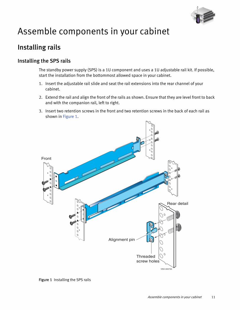
The standby power supply (SPS) is a 1U component and uses a 1U adjustable rail kit. If possible, start the installation from the bottommost allowed space in your cabinet.
1. Insert the adjustable rail slide and seat the rail extensions into the rear channel of your cabinet.
2. Extend the rail and align the front of the rails as shown. Ensure that they are level front to back and with the companion rail, left to right.
3. Insert two retention screws in the front and two retention screws in the back of each rail as shown in Figure 1.
Figure 1 Installing the SPS rails
Alignment pin
Threaded screw holes
VNX-000750
Rear detail
Front
Assemble components in your cabinet 11

Installing the DPE rails
The DPE rails should be installed immediately above the SPS rails.
Note: All rails must be aligned level front to back and with the companion rail, left to right.
1. Insert the adjustable 3U rail slide and seat both alignment pins into the rear channel of your cabinet.
2. Extend the rail and align the front of the rails as shown in Figure 2.
3. Insert two retention screws in the middle two holes in the front.
4. Insert two retention screws in the back of each rail.
Figure 2 Installing the DPE rails
RearDetail
2 Alignment
pins
2 Screws
VNX-000215
R
Front
L
12 EMC VNX5100 Installation Guide
Installing the components
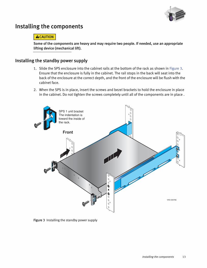
Some of the components are heavy and may require two people. If needed, use an appropriate lifting device (mechanical lift).
Installing the standby power supply
1. Slide the SPS enclosure into the cabinet rails at the bottom of the rack as shown in Figure 3. Ensure that the enclosure is fully in the cabinet. The rail stops in the back will seat into the back of the enclosure at the correct depth, and the front of the enclosure will be flush with the cabinet face.
2. When the SPS is in place, insert the screws and bezel brackets to hold the enclosure in place in the cabinet. Do not tighten the screws completely until all of the components are in place .
Figure 3 Installing the standby power supply
Front
SPS 1 unit bracket The indentation istoward the inside ofthe rack.
VNX-000766
Installing the components 13
Installing the disk processor enclosure
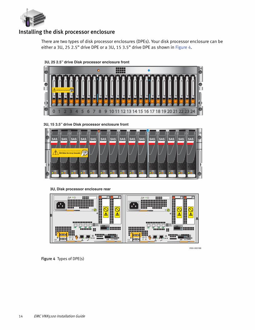
There are two types of disk processor enclosures (DPEs). Your disk processor enclosure can be either a 3U, 25 2.5” drive DPE or a 3U, 15 3.5” drive DPE as shown in Figure 4.
Figure 4 Types of DPE(s)
140
SAS SAS SAS SAS SAS SAS SAS SAS SAS SAS SAS SAS SAS SAS SAS
240
1 2 3 4 5 6 7 8 9 10 11 12 13 14 15 16 17 18 19 20 21 22 23 240
1 X42 3 4 5
6GbSAS
8Gbfibre
0 X46Gb SAS
A
2 3 4 5
6GbSAS
8Gbfibre
0 X46Gb SAS
B
1 X4
3U, 25 2.5” drive Disk processor enclosure front
3U, Disk processor enclosure rear
VNX-000188
3U, 15 3.5” drive Disk processor enclosure front
Will Make the Array Unusable Caution: Array Software on drives 0-3. Removing or relocating them
Will Make the Array Unusable Caution: Array Software on drives 0-3. Removing or relocating them
14 EMC VNX5100 Installation Guide

1. Locate the Product ID/SN from the product serial number tag (PSNT) located at the back of the DPE as shown in Figure 5.
2. Record this number to use when you register the product during system setup steps.
IMPORTANT
Be careful when you slide the enclosure into the rails. The PSNT tag on the corner of the enclosure as shown in Figure 5 can inadvertently become jammed, cut off, or block the enclosure’s seating.
Figure 5 PSNT tag on the rear of the 3U DPE
3. Slide the disk processor enclosure (DPE) into the 3U DPE rails in the cabinet. Ensure that the enclosure is fully in the cabinet. The rail stops in the back will seat into the back of the enclosure at the correct depth, and the front of the enclosure will be flush with the cabinet face.
4. When the DPE is in place, insert and tighten all of the screws as shown in Figure 6 on page 16. It may be easier to install the screws working in a diagonal pattern, such as bottom left and top right, bottom right and top left.
1 X42 3 4 5
6GbSAS
8Gbfibre
0 X46Gb SAS
A2 3 4 5
6GbSAS
8Gbfibre
0 X46Gb SAS
B 1 X4
VNX-000689
PSNT
Installing the components 15
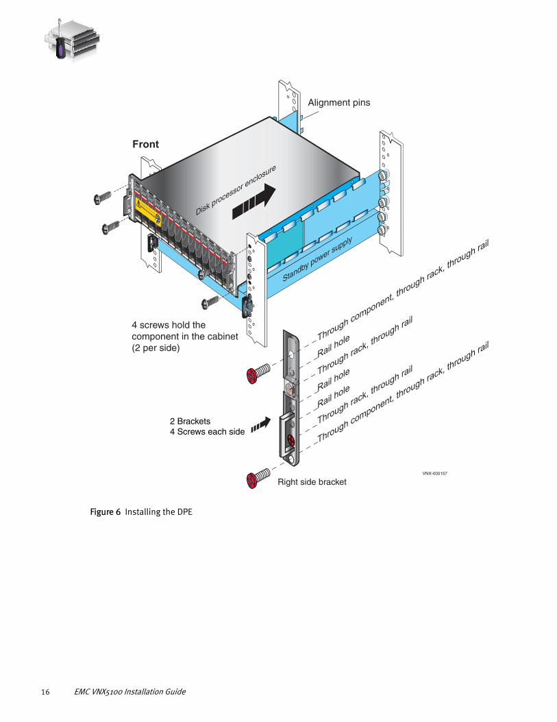
Figure 6 Installing the DPE
Disk processor enclosure
Standby power supply
Alignment pins
4 screws hold the component in the cabinet(2 per side)
VNX-000157
Front
SASSAS
SASSAS
SASSAS
SASSAS
SASSAS
SASSAS
SASSAS
SAS
Will Make the Array Unusable
Caution: Array Software on drives 0-4. Removing or relocating them
2 Brackets4 Screws each side
Right side bracket
Through rack, th
rough rail
Through component, through ra
ck, through ra
il
Through component, through ra
ck, through ra
il
Through rack, th
rough rail
Rail hole
Rail hole
Rail hole
16 EMC VNX5100 Installation Guide
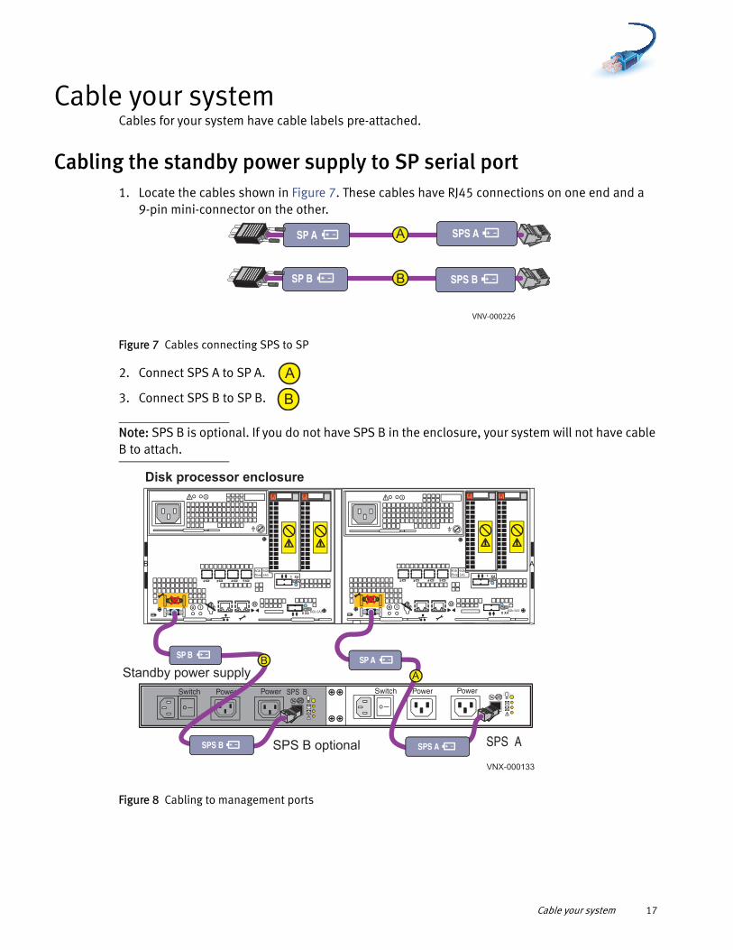
Cable your systemCables for your system have cable labels pre-attached.
Cabling the standby power supply to SP serial port1. Locate the cables shown in Figure 7. These cables have RJ45 connections on one end and a
9-pin mini-connector on the other.
Figure 7 Cables connecting SPS to SP
2. Connect SPS A to SP A.
3. Connect SPS B to SP B.
Note: SPS B is optional. If you do not have SPS B in the enclosure, your system will not have cable B to attach.
Figure 8 Cabling to management ports
A
B
SPS A
SPS B SP B
SP A
VNV-000226
A
B
SPS B
X42 3 4 5
6GbSAS
8Gbfibre 1
0 X4 6Gb SAS
01
23
X42 3 4 5
6GbSAS
8Gbfibre 1
0 X46Gb SAS
01
23
B A
PowerPowerSwitchPowerPowerSwitch
Standby power supply
Disk processor enclosure
SPS ASPS B optional
VNX-000133
BSP B SP A
SPS B SPS A
A
Cable your system 17

Attach system to the network
Attaching storage processors to the network
The storage processors and the Windows host from which you initialize the storage system must share the same subnet on your public LAN.
1. Locate your Ethernet cables.
Figure 9 Customer-supplied management cables
2. Connect your public LAN using a CAT 5e or better (customer-supplied) Ethernet cable to the RJ45 port on SP A . See cable A in Figure 10.
3. Connect your public LAN using a CAT 5e or better (customer-supplied) Ethernet cable to the RJ45 port on SP B . See cable B in Figure 10.
To public LAN (customer supplied)
To public LAN (customer supplied)
AAA
B
VNX-000225
18 EMC VNX5100 Installation Guide

Figure 10 Attaching the SPs to the network
1 X42 3 4 5
6GbSAS
8Gbfibre
0 X46Gb SAS
1 X42 3 4 5
6GbSAS
8Gbfibre
0 X46Gb SAS
BA
PowerPowerSwitchPowerPowerSwitch
B
VNX-000236
Rear
SPS ASPS B optional
SP B SP A
A
LAN
Attach system to the network 19

20 EMC VNX5100 Installation Guide
Power up
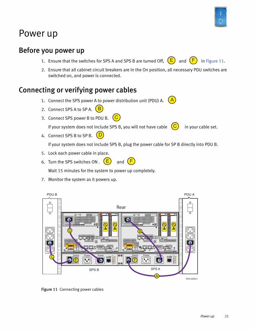
Before you power up1. Ensure that the switches for SPS A and SPS B are turned Off, and in Figure 11.
2. Ensure that all cabinet circuit breakers are in the On position, all necessary PDU switches are switched on, and power is connected.
Connecting or verifying power cables1. Connect the SPS power A to power distribution unit (PDU) A.
2. Connect SPS A to SP A.
3. Connect SPS power B to PDU B.
If your system does not include SPS B, you will not have cable in your cable set.
4. Connect SPS B to SP B.
If your system does not include SPS B, plug the power cable for SP B directly into PDU B.
5. Lock each power cable in place.
6. Turn the SPS switches ON . and
Wait 15 minutes for the system to power up completely.
7. Monitor the system as it powers up.
Figure 11 Connecting power cables
E F
A
B
C
C
D
E F
PowerPowerSwitchPowerPowerSwitch
X4
2 3 4 5
6Gb
SAS
8Gb
fibre 1
0 X46Gb SAS
X4
2 3 4 5
6Gb
SAS
8Gb
fibre 1
0 X4 6Gb SAS
C
B
A
PDU APDU B
VNX-000221
SPS B SPS A
Rear
E F
D
Power up 21

Verifying system statusWhile your system is powering up you will see green, blue, and amber activity lights blink. You can verify that your system powered up completely after 10-15 minutes.
Table 4 lists the LEDs that you need to focus on to ensure that the system is powered up correctly. The VNX5100 Hardware Information Guide provides details on all LEDs.
1. Verify that the DPE Power LED located on the front is solid blue and the DPE fault/status is off as shown in Figure 12.
Figure 12 3U, 15 3.5'' drive DPE and 3U, 25 2.5'' drive DPE LEDs
Table 4 DPE and SP LEDs
LEDs Location State/Color
DPE Power Front of unit On/Solid blue
DPE fault/status Front of unit Off
SP Power Rear of unit (SP A and SP B) On/Solid green
SP Fault Rear of unit (SP A and SP B) Off
SAS SAS SAS SAS SAS SAS SAS SAS SAS SAS SAS SAS SAS SAS SAS
3U, 15 disk DPE front DPE fault/status
Disk drive power
DPE Power
Disk drive fault/status
3U, 25 disk DPE front DPE fault/status DPE Power
Disk drive power
Disk drive fault/status
VNX-000228
Will Make the Array Unusable Caution: Array Software on drives 0-3. Removing or relocating them
Will Make the Array Unusable Caution: Array Software on drives 0-3. Removing or relocating them
22 EMC VNX5100 Installation Guide
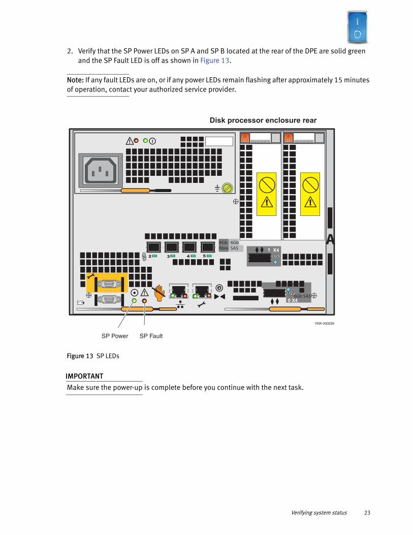
2. Verify that the SP Power LEDs on SP A and SP B located at the rear of the DPE are solid green and the SP Fault LED is off as shown in Figure 13.
Note: If any fault LEDs are on, or if any power LEDs remain flashing after approximately 15 minutes of operation, contact your authorized service provider.
Figure 13 SP LEDs
IMPORTANT
Make sure the power-up is complete before you continue with the next task.
X42 3 4 5
6GbSAS
8Gbfibre 1
0 X46Gb SAS
A
Disk processor enclosure rear
VNX-000226
SP FaultSP Power
Verifying system status 23

24 EMC VNX5100 Installation Guide

Add additional storageNote: The cabling examples described in this guide are for illustration purposes only. Your system cabling might be different based on how many DAEs you install and whether you use load balancing to install these DAEs.
Disk-array enclosure typesDAEs are optional components that add extra storage. DAEs come in:
◆ 2U, 25 2.5” drive DAE shown in Figure 14.
◆ 3U, 15 3.5” drive DAE shown in Figure 15 on page 26.
They use a 2U rail kit for the 25 2.5” drive DAE or a 3U rail kit for the 15 3.5” drive DAE.
If DAEs are used, the DAEs should be installed immediately above the DPE in the cabinet. Either type of DAE may be installed. The arrangement of the DAEs in a cabinet may depend upon a number of factors. The VNX5100 Hardware Information Guide provides more information on DAE assembling and arrangement.
Figure 14 2U, 25 2.5” drive DAE
240
2U, 25 2.5” drive DAE Front
Rear
6 G
bSA
S
X4
#
6 Gb
SAS
X4#
B
A
VNX-000227
Add additional storage 25

Figure 15 3U, 15 3.5” drive DAE
Assembling DAEs
The DAE is heavy and should be installed into a rack by two people. To avoid personal injury and/or damage to the equipment, do not attempt to lift and install the enclosure into a rack without a mechanical lift or help from another person.
1. Unpack the shipping containers.
2. Verify the contents. Each DAE should contain:
• Mounting screws
• Bezel and locking key
• SAS cable kit
• Power cable kit
• Rail kit
A
B #
X46Gb
SAS
#
X4
6Gb SA
S
3U, 15 3.5” drive Disk-array enclosure
RearVNX-000266
140
Front
SAS SAS SAS SAS SAS SAS SAS SAS SAS SAS SAS SAS SAS SAS SAS
26 EMC VNX5100 Installation Guide

3. Label the cables:
a. Locate a pair of DAE cables and the sheet of labels.
b. Attach the cable labels by matching the icons on the connectors with the icons on the labels as shown in Figure 16 and Figure 19 on page 30.
c. Continue for all the SAS cables for your system.
Figure 16 Attach labels to the SAS cables
Install DAE rails
1. Insert the adjustable rail slide and seat both alignment pins into the rear channel of your cabinet.
2. Extend the rail and align the front of the rails as shown in Figure 17.
Labels
VNX-000687
SPA S
AS 0
SP A SAS 0
SP A SAS 0
SP A SAS 0
SP A SAS 0
SP A SAS 0
SPA S
AS 0
SPA S
AS 0
SPA S
AS 0
Assembling DAEs 27

3. Insert two retention screws in the middle holes of the front and two retention screws in the back of each rail (3U rails). For 2U rails, insert one screw in the bottom hole of the front and two in the back of each rail.
Figure 17 Installing 3U DAE rails
Install the DAE
1. Slide the disk-array enclosure (DAE) into the DAE rails in the cabinet. Ensure that the enclosure is fully in the cabinet. The rail stops in the back will seat into the back of the enclosure at the correct depth, and the front of the enclosure will be flush with the cabinet face.
2. When the DAE is in place, insert and tighten all of the screws. It may be easier to install the screws working in a diagonal pattern, such as bottom left and top right, bottom right and top left.
3. Repeat, as appropriate, with other DAEs.
2 Alignment
pins
2 Screws
R
Front
2 screws
L
Reardetail
VNX-000216
28 EMC VNX5100 Installation Guide

Figure 18 Installing a 3U DAE in the cabinet
SASSAS
SASSAS SAS
SASSAS
SASSAS
SASSAS
SAS SASSAS
SASRR
VNX-000152
Right side bracket
Through rack, through rail
Through component, through rack, th
rough rail
Through component, through rack, th
rough rail
Through rack, through rail
Front
Assembling DAEs 29

Connect SAS DPE and DAE cables
In this example, two DAEs are being added. This example illustrates connecting one DAE to each of the ports available on the DPE. Each DAE has two Link Control Cards (LCC), designated A or B, as shown in Figure 15 on page 26.
1. Locate one pair of cables for each DAE as shown in Figure 19.
Figure 19 SAS cables for the first two DAEs
The SAS ports on the DPE are labeled 0 and 1. Port 0 is connected internally to the SAS expander that connects all the internal DPE disks. Since Port 0 is already connected internally to the DPE disks, the first DAE is connected to Port 1 to balance the load on the SAS ports. The second DAE is connected to Port 0.
Note: The VNX5100 Hardware Information Guide provides examples of how to cable DAEs in your VNX5100 for interleaved or stacked environments.
VNX-000268
D
C
A
B
LCC B
LCC A
LCC A
LCC B
SP B SAS 0
SP A SAS 0
SP A SAS 1
SP B SAS 1
30 EMC VNX5100 Installation Guide

For steps 2 through 5, connect the following cables by matching the double diamonds on the DPE and double circles on the DAEs with the single diamonds and single circles
on the cable connectors as shown in Figure 19 on page 30. Ensure that the cables lock into place.
2. Connect SP A SAS 1 ( ) to DAE 1 LCC A ( ).
3. Connect SP B SAS 1 ( ) to DAE 1 LCC B ( ).
4. Connect SP A SAS 0 ( ) to DAE 2 LCC A ( ).
5. Connect SP B SAS 0 ( ) to DAE 2 LCC B ( ).
Figure 20 Cabling the first two DAEs to the storage processors
A
B
C
D
A
B ##
X4
6Gb
SA
S
#
X4
6Gb
SAS
#
6 Gb
SAS
X4
#
2 3 4 5
6GbSAS
8Gbfibre 1 X4
6Gb SAS
X42 3 4 5
6GbSAS
8Gbfibre 1
0 X46Gb SAS
BA
PowerPowerSwitchPowerPowerSwitch
SP B SP A
0 X4
B
A
S SAS 1P A
6 G
bSA
S
X4
LCC B
D
SP B SAS 0
DAE 13U, 15 disk
Optional
DAE 22U, 25 disk
Optional
DPE
SPS
VNX-000772
Rear
LCC A
SPA SAS 0
C
A
LCC A
SPA SAS 1
B
SP B SAS 1
LCC B
Assembling DAEs 31
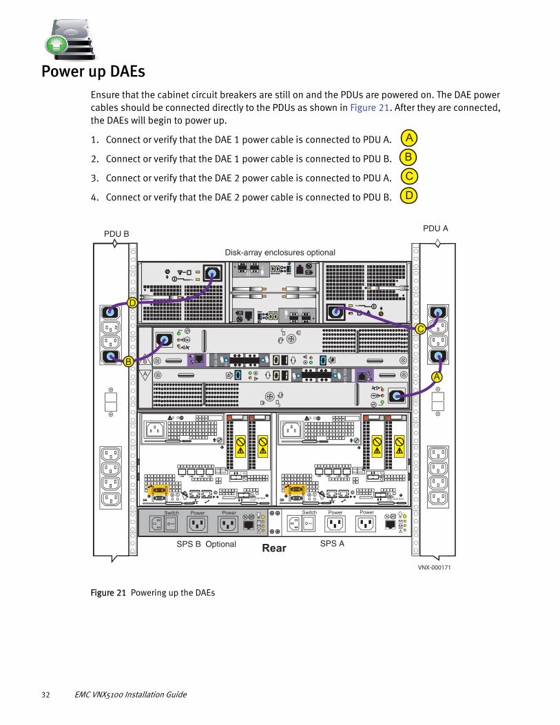
Power up DAEsEnsure that the cabinet circuit breakers are still on and the PDUs are powered on. The DAE power cables should be connected directly to the PDUs as shown in Figure 21. After they are connected, the DAEs will begin to power up.
1. Connect or verify that the DAE 1 power cable is connected to PDU A.
2. Connect or verify that the DAE 1 power cable is connected to PDU B.
3. Connect or verify that the DAE 2 power cable is connected to PDU A.
4. Connect or verify that the DAE 2 power cable is connected to PDU B.
Figure 21 Powering up the DAEs
A
B
C
D
A
B ##
X4
6G
b S
AS
#
X4
6G
b S
AS
PowerPowerSwitchPowerPowerSwitch
X4
2 3 4 5
6Gb
SAS
8Gb
fibre 1
0 X46Gb SAS
X4
2 3 4 5
6Gb
SAS
8Gb
fibre 1
0 X4 6Gb SAS
6 G
bSA
S
X4
#
6 Gb
SAS
X4
#
A
B
C
D
PDU APDU B
Disk-array enclosures optional
SPS B Optional SPS ARearVNX-000171
32 EMC VNX5100 Installation Guide
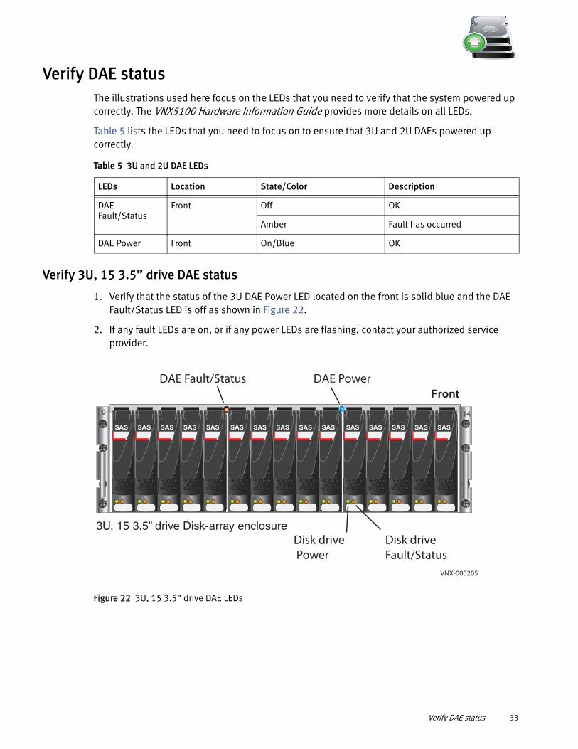
Verify DAE statusThe illustrations used here focus on the LEDs that you need to verify that the system powered up correctly. The VNX5100 Hardware Information Guide provides more details on all LEDs.
Table 5 lists the LEDs that you need to focus on to ensure that 3U and 2U DAEs powered up correctly.
Verify 3U, 15 3.5” drive DAE status
1. Verify that the status of the 3U DAE Power LED located on the front is solid blue and the DAE Fault/Status LED is off as shown in Figure 22.
2. If any fault LEDs are on, or if any power LEDs are flashing, contact your authorized service provider.
Figure 22 3U, 15 3.5” drive DAE LEDs
Table 5 3U and 2U DAE LEDs
LEDs Location State/Color Description
DAE Fault/Status
Front Off OK
Amber Fault has occurred
DAE Power Front On/Blue OK
3U, 15 3.5” drive Disk-array enclosure
140
Front
SAS SAS SAS SAS SAS SAS SAS SAS SAS SAS SAS SAS SAS SAS SAS
DAE Fault/Status DAE Power
Disk drive Power
Disk driveFault/Status
VNX-000205
Verify DAE status 33

Verify 2U, 25 2.5” drive DAE status
1. Verify that the status of the 2U DAE Power LED located on the front is solid blue and the DAE Fault/Status is off as shown in Figure 23.
2. If any fault LEDs are on, or if any power LEDs are flashing, contact your authorized service provider.
Figure 23 2U, 25 2.5" drive DAE LEDs
0 24
Front
2U, 25 Disk-array enclosureVNX-000233
DAE Fault/Status DAE Power
Disk drive Power Disk drive
Fault/Status
34 EMC VNX5100 Installation Guide

SetupAfter you have completed all of the installation steps, continue to set up your system by performing the post-installation tasks in this section.
Connect a management stationYou must connect a management station to your system directly or remotely over a subnetwork.
This computer will be used to continue setting up your system and must be on the same subnet as the storage system to complete the initialization.
Setting up a Unisphere Management Station for the VNX Series is available on https: //mydocs.emc.com/VNX/relatedDocs and provides information on different types of Unisphere management stations.
Initialize your storage systemIf your system shipped with a VNX Installation Toolbox (VIT) CD, use the Unisphere Storage System Initialization Utility located on the CD to initialize your system. If your system did not ship with a VIT CD, download the latest version of the VNX installation utilities from the Support website.
IMPORTANT
You will need the information from the “VNX Block Configuration Worksheet” on page 41 in the initialization process.
Downloading the Unisphere Storage System Initialization Wizard
1. Go to https://Support.EMC.com and select VNX Series > Install and Configure.
2. From VNX Installation Tools, download the Unisphere Storage System Initialization Wizard.
Note: If your host is behind a firewall, open the UDP ports 2162 (outgoing) and port 2163 (incoming). These ports are used by the initialization utility. If these ports are not opened, the initialization utility will not function properly.
3. Double-click the downloaded executable and follow the steps in the wizard to install the utility.
4. On the Install Complete screen, make sure that the Launch Unisphere Storage System Initialization Wizard checkbox is selected.
5. Click Done. The initialization utility opens. Follow the online instructions to discover and assign IP addresses to your storage system.
If you encounter any issues during initialization:
• Go to https: //mydocs.emc.com/VNX/and click Before you begin to read about known issues and suggestions.
Setup 35

• Go to https://Support.EMC.com, select VNX Series, click Search Support, and enter the specific failure message into the EMC Knowledgebase for possible resolution and corrective action.
Update the storage system software and register your systemThe storage system comes pre-installed with the latest version of VNX Operating Environment (OE) software available at the time of shipment. The Unisphere Service Manager (USM) is a collection of tools that helps you update, install, register, and maintain your system hardware and software. Use USM to check for and install an updated version of the VNX OE software and register your storage system.
Downloading USM documentation
1. Go to https://Support.EMC.com and download the Unisphere Service Manager Requirements and Installation document available on the VNX product page.
2. For additional information on using USM, go to https://mydocs.emc.com/VNX/.
3. Under VNX tasks, select Update VNX software.
4. Select appropriate settings for your configuration to generate a customized procedure.
Downloading Unisphere Service Manager
1. Go to https://Support.EMC.com and select VNX Series > Install and Configure.
2. From VNX Installation Tools, download Unisphere Service Manager.
3. Save the executable to your management station.
4. From the folder where you downloaded the executable, double-click the file and follow the wizard’s steps to install USM.
5. On the Install Complete screen, leave the Launch Unisphere Service Manager checkbox selected.
6. Click Done. Unisphere Service Manager opens.
7. Click Login.
8. Connect to your system by entering the host name or IP address and click Connect.
Downloading the latest version of the VNX operating environment software
1. Select Software > System Software.
2. Run the Prepare for Installation wizard to check for an updated version of the VNX OE.
3. If available, then run the Install Software wizard to install the update.
Registering your system for service with your service provider
1. Run the Storage System Registration wizard in Unisphere Service Manager.
36 EMC VNX5100 Installation Guide

2. From within the USM, select Register > Register Storage System.
3. Follow the steps in the wizard to complete the registration process.
You can also use USM to:
◆ Install and update Firmware
◆ Install language packs (if purchased)
◆ Install software enablers (if purchased)
Check system healthLogin to Unisphere to check the health of your system, including alerts, event logs, and statistics.
1. Open a browser and enter the IP address of SP A.
2. Use the sysadmin credentials to log in to Unisphere. You may be prompted by certificate-related warnings. Accept all certificates as "Always Trust".
3. Select your storage system and select System > Monitoring and Alerts.
Set the storage system cache values.You must allocate cache on the system. Allocate 10% of the available cache (with a minimum of 100 MB and a maximum of 1024 MB) to Read and the rest to Write.
Memory/Storage Processor:
Maximum RAM/SP (MB) 4000
Maximum Write Cache (MB) 801
1. Open a browser and enter the IP address of SP A.
2. Use the sysadmin credentials to log in to Unisphere. You may be prompted by certificate-related warnings. Accept all certificates as “Always Trust.”
3. Select your storage system and select System > Hardware > Storage Hardware.
4. From the task list, under System Management, select Manage Cache.
EMC Unified Storage Best Practices for Performance and Availability: Common Platform and Block Storage 31.5 - Applied Best Practices white paper available on https://Support.EMC.com provides more information on cache settings and recommendations.
Install ESRS and configure ConnectHome.You can ensure that your system communicates with your service provider by installing the VNX ESRS IP Client.
IMPORTANT
You will need the information from the ESRS Worksheet in this configuration.
Check system health 37

Downloading ESRS documentation
1. Go to https://mydocs.emc.com/VNX/.
2. Under VNX tasks, select Initialize and register VNX for block and configure ESRS.
3. Select the appropriate options for your configuration.
4. Select Install and Configure ESRS to generate a customized version of EMC Secure Remote Support IP Client for VNX Requirements and Installation document.
Downloading ESRS IP Client
1. Go to https://Support.EMC.com and select VNX Series > Install and Configure.
2. From VNX Installation Tools, download EMC Secure Remote Support IP Client.
3. Install the ESRS.
4. Follow the wizard to set up the ESRS and test the ConnectHome process.
Configure servers for VNX systemsGo to https: //mydocs.emc.com/VNX/ and from the Server tasks list, select an appropriate task such as:
◆ Attach server
◆ Install or update software (VNX for Block)
◆ Verify Server high availability, using Unisphere Server Utility
Provision storageProvisioning storage includes:
◆ Creating RAID groups/storage pools
◆ Creating LUNs
◆ Assigning LUNs to the host servers in its storage group
To provision storage:
1. Launch Unisphere and select your system.
2. Select Storage.
3. From the task list, under Wizards, select LUN Provisioning Wizard. Use this wizard to create LUNs and, optionally, assign the LUNs to a host/server system.
For more information on these tasks, follow the instructions in the Unisphere online help.
38 EMC VNX5100 Installation Guide

Attach bezelsWhen all of the components have been installed, all of the screws have been tightened, and all of the cables have been installed securely into the proper ports, return to the front of the site rack and select the correct bezel for the component and press the bezel into place on the front of the component.
1. Locate the bezel for each installed component.
2. On the front of the rack or cabinet, position and align each bezel to the front-mounting brackets on the corresponding component.
3. Press the bezel into the bracket until it clicks into place as shown in Figure 24 on page 39. Bezels have a lock built in to them, so you can opt to lock the bezels in place with the key provided.
4. Repeat steps 2 and 3 for the remaining bezels.
Figure 24 Attaching the bezels
Press each bezel to attach
Front
Will Make the Array Unusable
Caution: Array Software on drives 0-4. Removing or relocating them
VNX SERIES
VNX-000773
Attach bezels 39

40 EMC VNX5100 Installation Guide

Planning Worksheets
VNX Block Configuration WorksheetWith your network administrator, determine the IP addresses and network parameters you plan to use with the storage system, and record the information on the following worksheet. You must have this information to set up and initialize the system.
You manage the storage system through a dedicated LAN port on each storage processor. These ports must share a subnet with the host you use to initialize the system. After initialization, any host on the same network and with a supported browser can manage the system through the management ports.
Record network information for your system on the worksheets on the next pages. Your network administrator should provide most of this information. For more information, refer to your configuration planning guide.
Note: Do not use 128.221.1.248 through 128.221.1.255, 192.168.1.1, or 192.168.1.2 for an IPv4 IP address.
Table 6 IPv4 Management Port Information
IP Address Subnet mask Gateway
SP A
SP B
Table 7 IPv6 Management Port Information (optional; manual configuration only)
Global prefix
Gateway
Table 8 Login information for the storage system administrator
Field Description Value
Username User choice
Password User choice
Storage-system serial number
The serial number is located on the PSNT tag hanging from the rear of the DPE chassis. The number is identified as SN/Product ID.
Scope Global or Local
Planning Worksheets 41
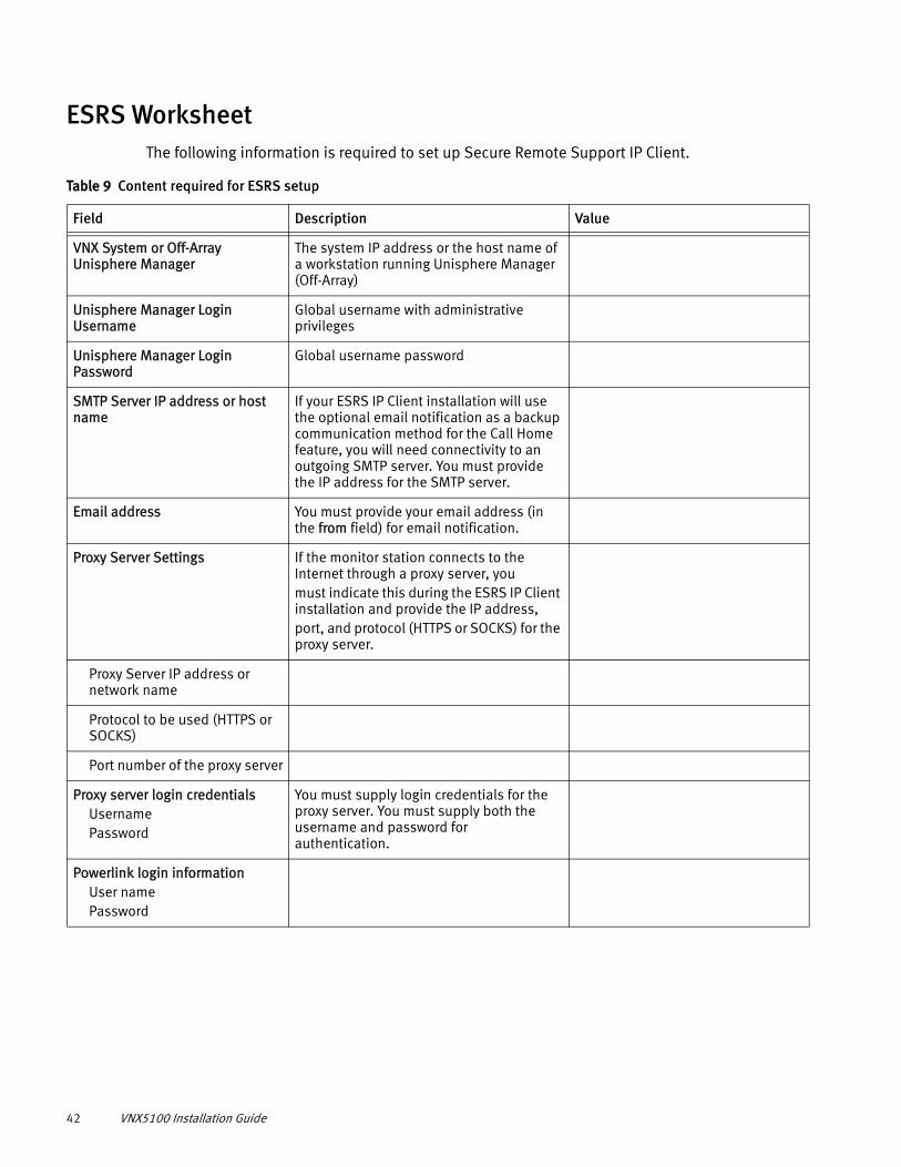
ESRS WorksheetThe following information is required to set up Secure Remote Support IP Client.
Table 9 Content required for ESRS setup
Field Description Value
VNX System or Off-Array Unisphere Manager
The system IP address or the host name of a workstation running Unisphere Manager (Off-Array)
Unisphere Manager Login Username
Global username with administrative privileges
Unisphere Manager Login Password
Global username password
SMTP Server IP address or host name
If your ESRS IP Client installation will use the optional email notification as a backup communication method for the Call Home feature, you will need connectivity to an outgoing SMTP server. You must provide the IP address for the SMTP server.
Email address You must provide your email address (in the from field) for email notification.
Proxy Server Settings If the monitor station connects to the Internet through a proxy server, youmust indicate this during the ESRS IP Client installation and provide the IP address,port, and protocol (HTTPS or SOCKS) for the proxy server.
Proxy Server IP address or network name
Protocol to be used (HTTPS or SOCKS)
Port number of the proxy server
Proxy server login credentialsUsernamePassword
You must supply login credentials for the proxy server. You must supply both the username and password for authentication.
Powerlink login informationUser namePassword
42 VNX5100 Installation Guide

